US6936008B2 - Ultrasound system with cableless coupling assembly - Google Patents
Ultrasound system with cableless coupling assemblyDownload PDFInfo
- Publication number
- US6936008B2 US6936008B2US10/039,910US3991001AUS6936008B2US 6936008 B2US6936008 B2US 6936008B2US 3991001 AUS3991001 AUS 3991001AUS 6936008 B2US6936008 B2US 6936008B2
- Authority
- US
- United States
- Prior art keywords
- acoustic
- signal generating
- posts
- conductors
- receiving unit
- Prior art date
- Legal status (The legal status is an assumption and is not a legal conclusion. Google has not performed a legal analysis and makes no representation as to the accuracy of the status listed.)
- Expired - Lifetime, expires
Links
- 238000002604ultrasonographyMethods0.000titleclaimsabstractdescription42
- 238000010168coupling processMethods0.000titleclaimsabstractdescription28
- 238000005859coupling reactionMethods0.000titleclaimsabstractdescription28
- 230000008878couplingEffects0.000titleclaimsabstractdescription27
- 239000004020conductorSubstances0.000claimsabstractdescription51
- 230000002463transducing effectEffects0.000claimsdescription59
- 239000000463materialSubstances0.000claimsdescription31
- 239000000945fillerSubstances0.000claimsdescription21
- 239000002245particleSubstances0.000claimsdescription17
- 239000011149active materialSubstances0.000claimsdescription3
- 230000005611electricityEffects0.000claimsdescription2
- 238000012285ultrasound imagingMethods0.000abstract1
- 238000000034methodMethods0.000description36
- 239000000853adhesiveSubstances0.000description21
- 230000001070adhesive effectEffects0.000description21
- 239000010408filmSubstances0.000description18
- 238000003384imaging methodMethods0.000description11
- 230000008569processEffects0.000description11
- 239000011248coating agentSubstances0.000description8
- 238000000576coating methodMethods0.000description8
- 238000003491arrayMethods0.000description6
- 238000009826distributionMethods0.000description6
- 239000000203mixtureSubstances0.000description6
- 238000002955isolationMethods0.000description5
- PXHVJJICTQNCMI-UHFFFAOYSA-NNickelChemical compound[Ni]PXHVJJICTQNCMI-UHFFFAOYSA-N0.000description4
- 238000001514detection methodMethods0.000description4
- 230000007340echolocationEffects0.000description4
- 239000004005microsphereSubstances0.000description4
- 230000035945sensitivityEffects0.000description4
- RYGMFSIKBFXOCR-UHFFFAOYSA-NCopperChemical compound[Cu]RYGMFSIKBFXOCR-UHFFFAOYSA-N0.000description3
- 239000004593EpoxySubstances0.000description3
- 239000000919ceramicSubstances0.000description3
- 239000002131composite materialSubstances0.000description3
- 238000010276constructionMethods0.000description3
- 230000007274generation of a signal involved in cell-cell signalingEffects0.000description3
- 238000011835investigationMethods0.000description3
- 238000005304joiningMethods0.000description3
- 238000004519manufacturing processMethods0.000description3
- 230000003287optical effectEffects0.000description3
- 229920001296polysiloxanePolymers0.000description3
- 229920002635polyurethanePolymers0.000description3
- 239000004814polyurethaneSubstances0.000description3
- VYZAMTAEIAYCRO-UHFFFAOYSA-NChromiumChemical compound[Cr]VYZAMTAEIAYCRO-UHFFFAOYSA-N0.000description2
- BQCADISMDOOEFD-UHFFFAOYSA-NSilverChemical compound[Ag]BQCADISMDOOEFD-UHFFFAOYSA-N0.000description2
- ATJFFYVFTNAWJD-UHFFFAOYSA-NTinChemical compound[Sn]ATJFFYVFTNAWJD-UHFFFAOYSA-N0.000description2
- 239000000654additiveSubstances0.000description2
- 239000000956alloySubstances0.000description2
- 229910045601alloyInorganic materials0.000description2
- 230000015572biosynthetic processEffects0.000description2
- -1bubblesSubstances0.000description2
- 229910052804chromiumInorganic materials0.000description2
- 239000011651chromiumSubstances0.000description2
- 229910052802copperInorganic materials0.000description2
- 239000010949copperSubstances0.000description2
- 238000002592echocardiographyMethods0.000description2
- 239000011521glassSubstances0.000description2
- PCHJSUWPFVWCPO-UHFFFAOYSA-NgoldChemical compound[Au]PCHJSUWPFVWCPO-UHFFFAOYSA-N0.000description2
- 229910052737goldInorganic materials0.000description2
- 239000010931goldSubstances0.000description2
- 229910052738indiumInorganic materials0.000description2
- APFVFJFRJDLVQX-UHFFFAOYSA-Nindium atomChemical compound[In]APFVFJFRJDLVQX-UHFFFAOYSA-N0.000description2
- 229910003437indium oxideInorganic materials0.000description2
- PJXISJQVUVHSOJ-UHFFFAOYSA-Nindium(iii) oxideChemical compound[O-2].[O-2].[O-2].[In+3].[In+3]PJXISJQVUVHSOJ-UHFFFAOYSA-N0.000description2
- 239000012212insulatorSubstances0.000description2
- 229910052759nickelInorganic materials0.000description2
- 239000004033plasticSubstances0.000description2
- 229920003023plasticPolymers0.000description2
- 229920000642polymerPolymers0.000description2
- 238000012545processingMethods0.000description2
- 230000004044responseEffects0.000description2
- 229910052709silverInorganic materials0.000description2
- 239000004332silverSubstances0.000description2
- 239000010409thin filmSubstances0.000description2
- 229910052718tinInorganic materials0.000description2
- 239000011135tinSubstances0.000description2
- XOLBLPGZBRYERU-UHFFFAOYSA-Ntin dioxideChemical compoundO=[Sn]=OXOLBLPGZBRYERU-UHFFFAOYSA-N0.000description2
- 229910001887tin oxideInorganic materials0.000description2
- 238000012546transferMethods0.000description2
- WFKWXMTUELFFGS-UHFFFAOYSA-NtungstenChemical compound[W]WFKWXMTUELFFGS-UHFFFAOYSA-N0.000description2
- 229910052721tungstenInorganic materials0.000description2
- 239000010937tungstenSubstances0.000description2
- 230000005641tunnelingEffects0.000description2
- OKTJSMMVPCPJKN-UHFFFAOYSA-NCarbonChemical compound[C]OKTJSMMVPCPJKN-UHFFFAOYSA-N0.000description1
- 238000004458analytical methodMethods0.000description1
- 230000000712assemblyEffects0.000description1
- 238000000429assemblyMethods0.000description1
- 230000002238attenuated effectEffects0.000description1
- DUPIXUINLCPYLU-UHFFFAOYSA-Nbarium leadChemical compound[Ba].[Pb]DUPIXUINLCPYLU-UHFFFAOYSA-N0.000description1
- 229910002113barium titanateInorganic materials0.000description1
- JRPBQTZRNDNNOP-UHFFFAOYSA-Nbarium titanateChemical compound[Ba+2].[Ba+2].[O-][Ti]([O-])([O-])[O-]JRPBQTZRNDNNOP-UHFFFAOYSA-N0.000description1
- 230000008901benefitEffects0.000description1
- 230000005540biological transmissionEffects0.000description1
- 229910010293ceramic materialInorganic materials0.000description1
- 239000002872contrast mediaSubstances0.000description1
- 239000011889copper foilSubstances0.000description1
- 238000007405data analysisMethods0.000description1
- 238000000151depositionMethods0.000description1
- 230000008021depositionEffects0.000description1
- 238000013461designMethods0.000description1
- 239000003814drugSubstances0.000description1
- 238000005516engineering processMethods0.000description1
- 239000003822epoxy resinSubstances0.000description1
- 230000003628erosive effectEffects0.000description1
- 229910002804graphiteInorganic materials0.000description1
- 239000010439graphiteSubstances0.000description1
- 239000011810insulating materialSubstances0.000description1
- 150000002500ionsChemical class0.000description1
- 229910052451lead zirconate titanateInorganic materials0.000description1
- HFGPZNIAWCZYJU-UHFFFAOYSA-Nlead zirconate titanateChemical compound[O-2].[O-2].[O-2].[O-2].[O-2].[Ti+4].[Zr+4].[Pb+2]HFGPZNIAWCZYJU-UHFFFAOYSA-N0.000description1
- 239000007788liquidSubstances0.000description1
- GQYHUHYESMUTHG-UHFFFAOYSA-Nlithium niobateChemical compound[Li+].[O-][Nb](=O)=OGQYHUHYESMUTHG-UHFFFAOYSA-N0.000description1
- INHCSSUBVCNVSK-UHFFFAOYSA-Llithium sulfateInorganic materials[Li+].[Li+].[O-]S([O-])(=O)=OINHCSSUBVCNVSK-UHFFFAOYSA-L0.000description1
- 238000001465metallisationMethods0.000description1
- 238000012986modificationMethods0.000description1
- 230000004048modificationEffects0.000description1
- 230000010355oscillationEffects0.000description1
- 230000000737periodic effectEffects0.000description1
- 230000003094perturbing effectEffects0.000description1
- 229920000647polyepoxidePolymers0.000description1
- 239000011253protective coatingSubstances0.000description1
- 239000010453quartzSubstances0.000description1
- 230000035939shockEffects0.000description1
- 230000008054signal transmissionEffects0.000description1
- VYPSYNLAJGMNEJ-UHFFFAOYSA-Nsilicon dioxideInorganic materialsO=[Si]=OVYPSYNLAJGMNEJ-UHFFFAOYSA-N0.000description1
- 229910000679solderInorganic materials0.000description1
- 230000005236sound signalEffects0.000description1
- 238000001228spectrumMethods0.000description1
- 239000000126substanceSubstances0.000description1
- RBTVSNLYYIMMKS-UHFFFAOYSA-Ntert-butyl 3-aminoazetidine-1-carboxylate;hydrochlorideChemical compoundCl.CC(C)(C)OC(=O)N1CC(N)C1RBTVSNLYYIMMKS-UHFFFAOYSA-N0.000description1
- 230000007704transitionEffects0.000description1
- 238000012800visualizationMethods0.000description1
- 239000011800void materialSubstances0.000description1
- 238000003466weldingMethods0.000description1
Images


Classifications
- A—HUMAN NECESSITIES
- A61—MEDICAL OR VETERINARY SCIENCE; HYGIENE
- A61B—DIAGNOSIS; SURGERY; IDENTIFICATION
- A61B8/00—Diagnosis using ultrasonic, sonic or infrasonic waves
- A61B8/08—Clinical applications
- A—HUMAN NECESSITIES
- A61—MEDICAL OR VETERINARY SCIENCE; HYGIENE
- A61B—DIAGNOSIS; SURGERY; IDENTIFICATION
- A61B8/00—Diagnosis using ultrasonic, sonic or infrasonic waves
- A61B8/44—Constructional features of the ultrasonic, sonic or infrasonic diagnostic device
- A61B8/4438—Means for identifying the diagnostic device, e.g. barcodes
- A—HUMAN NECESSITIES
- A61—MEDICAL OR VETERINARY SCIENCE; HYGIENE
- A61B—DIAGNOSIS; SURGERY; IDENTIFICATION
- A61B8/00—Diagnosis using ultrasonic, sonic or infrasonic waves
- A61B8/44—Constructional features of the ultrasonic, sonic or infrasonic diagnostic device
- A61B8/4444—Constructional features of the ultrasonic, sonic or infrasonic diagnostic device related to the probe
- A61B8/4455—Features of the external shape of the probe, e.g. ergonomic aspects
- A—HUMAN NECESSITIES
- A61—MEDICAL OR VETERINARY SCIENCE; HYGIENE
- A61B—DIAGNOSIS; SURGERY; IDENTIFICATION
- A61B8/00—Diagnosis using ultrasonic, sonic or infrasonic waves
- A61B8/44—Constructional features of the ultrasonic, sonic or infrasonic diagnostic device
- A61B8/4444—Constructional features of the ultrasonic, sonic or infrasonic diagnostic device related to the probe
- A61B8/4472—Wireless probes
- G—PHYSICS
- G01—MEASURING; TESTING
- G01S—RADIO DIRECTION-FINDING; RADIO NAVIGATION; DETERMINING DISTANCE OR VELOCITY BY USE OF RADIO WAVES; LOCATING OR PRESENCE-DETECTING BY USE OF THE REFLECTION OR RERADIATION OF RADIO WAVES; ANALOGOUS ARRANGEMENTS USING OTHER WAVES
- G01S15/00—Systems using the reflection or reradiation of acoustic waves, e.g. sonar systems
- G01S15/88—Sonar systems specially adapted for specific applications
- G01S15/89—Sonar systems specially adapted for specific applications for mapping or imaging
- G01S15/8906—Short-range imaging systems; Acoustic microscope systems using pulse-echo techniques
- G01S15/8979—Combined Doppler and pulse-echo imaging systems
- G01S15/8981—Discriminating between fixed and moving objects or between objects moving at different speeds, e.g. wall clutter filter
- G—PHYSICS
- G01—MEASURING; TESTING
- G01S—RADIO DIRECTION-FINDING; RADIO NAVIGATION; DETERMINING DISTANCE OR VELOCITY BY USE OF RADIO WAVES; LOCATING OR PRESENCE-DETECTING BY USE OF THE REFLECTION OR RERADIATION OF RADIO WAVES; ANALOGOUS ARRANGEMENTS USING OTHER WAVES
- G01S7/00—Details of systems according to groups G01S13/00, G01S15/00, G01S17/00
- G01S7/52—Details of systems according to groups G01S13/00, G01S15/00, G01S17/00 of systems according to group G01S15/00
- G01S7/52017—Details of systems according to groups G01S13/00, G01S15/00, G01S17/00 of systems according to group G01S15/00 particularly adapted to short-range imaging
- G01S7/52023—Details of receivers
- G01S7/52034—Data rate converters
- G—PHYSICS
- G01—MEASURING; TESTING
- G01S—RADIO DIRECTION-FINDING; RADIO NAVIGATION; DETERMINING DISTANCE OR VELOCITY BY USE OF RADIO WAVES; LOCATING OR PRESENCE-DETECTING BY USE OF THE REFLECTION OR RERADIATION OF RADIO WAVES; ANALOGOUS ARRANGEMENTS USING OTHER WAVES
- G01S7/00—Details of systems according to groups G01S13/00, G01S15/00, G01S17/00
- G01S7/52—Details of systems according to groups G01S13/00, G01S15/00, G01S17/00 of systems according to group G01S15/00
- G01S7/52017—Details of systems according to groups G01S13/00, G01S15/00, G01S17/00 of systems according to group G01S15/00 particularly adapted to short-range imaging
- G01S7/52079—Constructional features
- G01S7/5208—Constructional features with integration of processing functions inside probe or scanhead
- G—PHYSICS
- G01—MEASURING; TESTING
- G01S—RADIO DIRECTION-FINDING; RADIO NAVIGATION; DETERMINING DISTANCE OR VELOCITY BY USE OF RADIO WAVES; LOCATING OR PRESENCE-DETECTING BY USE OF THE REFLECTION OR RERADIATION OF RADIO WAVES; ANALOGOUS ARRANGEMENTS USING OTHER WAVES
- G01S7/00—Details of systems according to groups G01S13/00, G01S15/00, G01S17/00
- G01S7/52—Details of systems according to groups G01S13/00, G01S15/00, G01S17/00 of systems according to group G01S15/00
- G01S7/52017—Details of systems according to groups G01S13/00, G01S15/00, G01S17/00 of systems according to group G01S15/00 particularly adapted to short-range imaging
- G01S7/52079—Constructional features
- G01S7/52082—Constructional features involving a modular construction, e.g. a computer with short range imaging equipment
- G—PHYSICS
- G01—MEASURING; TESTING
- G01S—RADIO DIRECTION-FINDING; RADIO NAVIGATION; DETERMINING DISTANCE OR VELOCITY BY USE OF RADIO WAVES; LOCATING OR PRESENCE-DETECTING BY USE OF THE REFLECTION OR RERADIATION OF RADIO WAVES; ANALOGOUS ARRANGEMENTS USING OTHER WAVES
- G01S7/00—Details of systems according to groups G01S13/00, G01S15/00, G01S17/00
- G01S7/52—Details of systems according to groups G01S13/00, G01S15/00, G01S17/00 of systems according to group G01S15/00
- G01S7/52017—Details of systems according to groups G01S13/00, G01S15/00, G01S17/00 of systems according to group G01S15/00 particularly adapted to short-range imaging
- G01S7/52079—Constructional features
- G01S7/52084—Constructional features related to particular user interfaces
- G—PHYSICS
- G01—MEASURING; TESTING
- G01S—RADIO DIRECTION-FINDING; RADIO NAVIGATION; DETERMINING DISTANCE OR VELOCITY BY USE OF RADIO WAVES; LOCATING OR PRESENCE-DETECTING BY USE OF THE REFLECTION OR RERADIATION OF RADIO WAVES; ANALOGOUS ARRANGEMENTS USING OTHER WAVES
- G01S7/00—Details of systems according to groups G01S13/00, G01S15/00, G01S17/00
- G01S7/52—Details of systems according to groups G01S13/00, G01S15/00, G01S17/00 of systems according to group G01S15/00
- G01S7/52017—Details of systems according to groups G01S13/00, G01S15/00, G01S17/00 of systems according to group G01S15/00 particularly adapted to short-range imaging
- G01S7/52096—Details of systems according to groups G01S13/00, G01S15/00, G01S17/00 of systems according to group G01S15/00 particularly adapted to short-range imaging related to power management, e.g. saving power or prolonging life of electronic components
- A—HUMAN NECESSITIES
- A61—MEDICAL OR VETERINARY SCIENCE; HYGIENE
- A61B—DIAGNOSIS; SURGERY; IDENTIFICATION
- A61B8/00—Diagnosis using ultrasonic, sonic or infrasonic waves
- A61B8/06—Measuring blood flow
- A—HUMAN NECESSITIES
- A61—MEDICAL OR VETERINARY SCIENCE; HYGIENE
- A61B—DIAGNOSIS; SURGERY; IDENTIFICATION
- A61B8/00—Diagnosis using ultrasonic, sonic or infrasonic waves
- A61B8/08—Clinical applications
- A61B8/0833—Clinical applications involving detecting or locating foreign bodies or organic structures
- A—HUMAN NECESSITIES
- A61—MEDICAL OR VETERINARY SCIENCE; HYGIENE
- A61B—DIAGNOSIS; SURGERY; IDENTIFICATION
- A61B8/00—Diagnosis using ultrasonic, sonic or infrasonic waves
- A61B8/08—Clinical applications
- A61B8/0866—Clinical applications involving foetal diagnosis; pre-natal or peri-natal diagnosis of the baby
- A—HUMAN NECESSITIES
- A61—MEDICAL OR VETERINARY SCIENCE; HYGIENE
- A61B—DIAGNOSIS; SURGERY; IDENTIFICATION
- A61B8/00—Diagnosis using ultrasonic, sonic or infrasonic waves
- A61B8/13—Tomography
- A—HUMAN NECESSITIES
- A61—MEDICAL OR VETERINARY SCIENCE; HYGIENE
- A61B—DIAGNOSIS; SURGERY; IDENTIFICATION
- A61B8/00—Diagnosis using ultrasonic, sonic or infrasonic waves
- A61B8/48—Diagnostic techniques
- A61B8/488—Diagnostic techniques involving Doppler signals
- G—PHYSICS
- G01—MEASURING; TESTING
- G01S—RADIO DIRECTION-FINDING; RADIO NAVIGATION; DETERMINING DISTANCE OR VELOCITY BY USE OF RADIO WAVES; LOCATING OR PRESENCE-DETECTING BY USE OF THE REFLECTION OR RERADIATION OF RADIO WAVES; ANALOGOUS ARRANGEMENTS USING OTHER WAVES
- G01S15/00—Systems using the reflection or reradiation of acoustic waves, e.g. sonar systems
- G01S15/88—Sonar systems specially adapted for specific applications
- G01S15/89—Sonar systems specially adapted for specific applications for mapping or imaging
- G01S15/8906—Short-range imaging systems; Acoustic microscope systems using pulse-echo techniques
- G01S15/8979—Combined Doppler and pulse-echo imaging systems
Definitions
- the inventionis in the field of imaging devices and more particularly in the field of portable high-resolution three-dimensional ultrasonic imaging.
- Ultrasonic imagingis a frequently used method of analysis. The technique is used to examine a wide range of materials and is especially common in medicine because of its relatively non-invasive nature, low cost, and fast response times.
- ultrasonic imagingis accomplished by generating and directing ultrasonic waves into a material under investigation.
- This ultrasonic imaginguses a set of ultrasound generating transducers and then observing reflections generated at the boundaries of dissimilar materials, such as tissues within a patient, also uses a set of ultrasound receiving transducers.
- the receiving and generating transducersmay be arranged in arrays and are typically different sets of transducers but may differ only in the circuitry to which they are connected.
- the reflectionsare converted to electrical signals by the receiving transducers and then processed, using techniques known in the art, to determine the locations of echo sources.
- the resulting datais displayed using a display device, such as a monitor.
- the beam intensity as a function of positionmay oscillate rather than fall off monotonically as a function of distance from the center of the beam. These oscillations in beam intensity are often called “side lobes.”
- the term “apodisation”refers to the process of affecting the distribution of beam intensity to reduce side lobes. However, in the remainder of this specification the term “apodisation” is used to refer to tailoring the distribution of beam intensity for a desired beam characteristic such as having a Guassian or sinc function distribution of beam intensity (without the side lobes).
- Steeringrefers to changing the direction of a beam.
- Aperturerefers to the size of the transducer or group of transducers being used to transmit or receive an acoustic beam.
- the prior art process of producing, receiving, and analyzing an ultrasonic beamis called beam forming.
- the production of ultrasonic beamsoptionally includes apodisation, steering, focusing, and aperture.
- each ultrasonic beamis used to generate a one dimensional set of echolocation data.
- a plurality of ultrasonic beamsare used to scan a multi-dimensional volume.
- the ultrasonic signal transmitted into the material under investigationis generated by applying continuous or pulsed electronic signals to a transducer.
- the transmitted ultrasoundis commonly in the range of 40 kHz to 10 MHz.
- the ultrasonic beampropagates through the material under investigation and reflects off of structures such as boundaries between adjacent tissue layers. As it travels, the ultrasonic energy may be scattered, resonated, attenuated, reflected, or transmitted. A portion of the reflected signals are returned to the transducers and detected as echoes.
- the detecting transducersconvert the echo signals to electronic signals for processing using simple filters and signal averagers.
- an image scan converteruses the calculated positional information to generate two dimensional data that can be presented as an image.
- the image formation rate(the frame rate) is limited by at least the return time of an ultrasonic pulse.
- the pulse return timeis the time between the transmission of ultrasound into the media of interest and the detection of the last reflected signals.
- harmonic frequency componentsare generated, which are analyzed and associated with the visualization of boundaries, or image contrast agents designed to re-radiate ultrasound at specific harmonic frequencies. Unwanted reflections within the ultrasound device can cause noise and the appearance of artifacts in the image.
- One-dimensional acoustic arrayshave a depth of focus that is usually determined by a nonadjustable passive acoustic focusing means that is affixed to each transducer. This type of focusing necessitates using different transducers for different applications with different depths of focus.
- Two-dimensional transducer arrays used for high-speed three-dimensional imaging applicationssuffer from sensitivity loss caused by coupling multiple signal transfer and distribution systems to ultrasound systems.
- Two-dimensional transducers used for high-speed three-dimensional imaging applicationsmust have a large number of pixels for two-dimensional steering capability with high resolution.
- High numbers of radiating/receiving pixelsinevitably result in high electrical impedances per pixel in many types of transducers (e.g., piezoelectric, capacitive Micro ElectroMechanical (MEM) transducers), making high-resolution two-dimensional arrays impractical.
- MEMMicro ElectroMechanical
- each pixelmay contain one transmitting and one receiving transducer element.
- FIG. 1shows a prior art ultrasonic imaging device 100 , including a system 102 , a first connector 104 , a cable 106 , a second connector 108 , and a hand held unit 109 , which includes a multilayer structure 110 for transmitting the signal, interposing electrical connector structure (not shown), acoustic elements 114 , and pins 116 .
- System 102may include a systems motherboard.
- the multilayer structure 110could be a PCB, co-fired ceramic board, or flex circuits, for example.
- the interposing electrical connector structure (not shown)could be an interposing media for carrying signals from the multilayer structure 110 to acoustic elements 114 .
- Handheld unit 109has electrical contact pads 116 for individually powering the acoustic elements 114 .
- An embodiment of the inventionprovides a miniaturized ultrasound system generating and receiving unit such as a motherboard with two-dimensional signal addressing capability whereby first connector 104 , cable 106 , and second connector 108 of the prior art device in FIG. 1 can be eliminated.
- the systemmay have a system motherboard coupled via a cableless coupling to a transducer array.
- the cableless couplingis also wireless (e.g., using the radio-frequency spectrum for transmitting and receiving data and signals).
- the systemmay include a two-dimensional surface interconnection between the transducer array and the signal generation and/or detection system, which eliminates the impractically thick and heavy cable.
- the signal generation and/or detection systemmay be electrically matched to the transducer elements increasing the sensitivity more than were transducer elements not matched to the signal generation and/or detection system.
- the two-dimensional interconnection on the motherboardmay be used without any other two-dimensional interconnection.
- the electrical connection to the two-dimensional array elementsare made via many flex circuits (e.g., printed circuit patterns using a layer of copper foil over a polymer base allowing for multidimensionality whereby the circuit may move, bend and twist without damage to the conductor), each coming from one row of elements, which may be terminated directly on the motherboard row of pads. Flex circuits should not be confused with ribbon cables (e.g., those cables made of normal, round insulated wires arranged side-by-side and fastened together by a cohesion process to form a flexible ribbon).
- the two-dimensional arraymay perform multiple tasks.
- the motherboard system and the transducersmay be designed to provide a sufficient percentage of the bandwidth for multiple frequency operations. For example, for many ultrasound transducers 100% of the bandwidth is necessary for multiple frequency operations.
- the depth of focusis not fixed by the physical construction of the array, but is controlled by the area forming electronics and the system software, by active electrical phasing of the two-dimensional array elements. Alternatively, different transducers for different applications with different depths of focus can be used.
- a high density connectori.e., a connector having a high density of connector contact pads, one pad for each transducer element (e.g., pixel) of the two-dimensional array
- a high density connectori.e., a connector having a high density of connector contact pads, one pad for each transducer element (e.g., pixel) of the two-dimensional array
- the inventionmay provide acoustically attenuating mounting posts with low electrical resistance, for example, and allow the two-dimensional arrays of acoustical elements to have a higher sensitivity than were the posts not present.
- the height of the postsallows the transducer to be oriented for convenient use even though it is an integral part of the motherboard, an other interconnection device, or an other system for example.
- the permanent connection with the motherboardrequires the design of the transducer to provide sufficient bandwidth for multiple frequency operation.
- the two-dimensional arrayis permanently integrated with the motherboard.
- the depth of focus of the two-dimensional arrayis not fixed by the physical construction of the array, but is controlled by the area forming electronics and system software, which determine the active phasing of the two-dimensional array elements.
- This method of controleliminates the necessity of using different transducers for different applications with different fixed depths of focus and allows one transducer affixed to the motherboard, for example, to perform multiple tasks.
- different two-dimensional arrays with different depths of focus, frequency, and other characteristicscan be plugged to the system motherboard without an intervening cable via the high density connector.
- Broad beam technologiesrefer to systems and methods that include or take advantage of techniques for generating ultrasound and analyzing detected echoes such that multi-dimensional spatial information obtainable from a single ultrasonic pulse.
- Area formingis the process of producing, receiving, and analyzing an ultrasonic beam, that optionally includes apodisation, steering, focusing, and aperture control, where a two dimensional set of echolocation data can be generated using only one ultrasonic beam. Nonetheless, more than one ultrasonic beam may still be used with the area forming even though only one is necessary.
- Area formingis a process separate and distinct from beam forming. Area forming may yield an area of information one transmit and/or receive cycle, in contrast to beam forming that typically only processes a line of information per transmit and/or receive cycle. Alternatively, beam forming can be used instead of area forming electronics throughout this application.
- Volume formingis the process of producing, receiving, and analyzing an ultrasonic beam, that optionally includes apodisation, steering, focusing, and aperture control, where a three dimensional set of echolocation data can be generated using only one ultrasonic beam. Nonetheless, multiple ultrasonic beams may be used although not necessary. Volume forming is a superset of area forming.
- Multidimensional formingis the process of producing, receiving, and analyzing an ultrasonic beam, that optionally includes apodisation, steering, focusing, and apertures, wherein a two or more dimensional set of spatial echolocation data can be generated using only one ultrasonic beam. Nonetheless, multiple ultrasonic beams may be used although not necessary.
- Multidimensional formingoptionally includes non-spatial dimensions such as time and velocity.
- the motherboardis specified as the signal generating and receiving unit, it is only by way of example and any signal generating and receiving unit can be used.
- FIG. 1is a prior art ultrasound device
- FIG. 2is an overview of an embodiment of the invention
- FIG. 3shows the details of the structure of FIG. 2 according to an embodiment of the invention
- FIG. 4is an alternative embodiment of the structure of FIG. 2 ;
- FIG. 5is a more detailed illustration of FIG. 4 ;
- FIG. 6is another embodiment of the structure of FIG. 2 ;
- FIG. 7is another embodiment of the structure of FIG. 2 ;
- FIG. 8is another embodiment of the structure of FIG. 2 ;
- FIG. 9is another embodiment of the structure of FIG. 2 ;
- FIG. 10is another embodiment of the structure of FIG. 2 ;
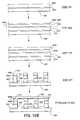
- FIG. 11Ais a flowchart of a method of transmitting an acoustic signal
- FIG. 11Bis a flowchart of a method of receiving an acoustic signal
- FIG. 12Ais a flowchart of a method of making an embodiment of the invention.
- FIG. 12Billustrates the structure at various stages of the method of FIG. 12A ;
- FIG. 13Ais a flowchart of a method of making an embodiment of the invention of FIGS. 4-10 ;
- FIG. 13Billustrates the structure at various stages of the method of FIG. 13A ;
- FIG. 14is a flowchart of a method for making intermediate elements of an embodiment of the invention.
- FIG. 2is an overview of one embodiment of the invention.
- FIG. 2shows a handheld ultrasound device 200 that includes an ultrasound transducing structure 202 coupled via a cableless coupling 203 to a signal generating and receiving unit 210 .
- the cableless coupling 203includes an intermediate structure 204 , an electrically conducting structure 206 , a connector 208 .
- the connector 208is coupled to the signal generating and receiving unit 210 , which are secured within housing 212 , and cooperates with cableless coupling 203 .
- the signals from or to intermediate structure 204pass through electrically conducting structure 206 , connector 208 , and the signal generating and receiving unit 210 .
- Ultrasound transducing structure 202generates, or pulses, in response to signals received via intermediate structure 204 , or receives ultrasonic waves and converts them to electrical signals, then sends them to intermediate structure 204 .
- cableless coupling 203is also wireless.
- Signal generating and receiving unit 210can be an integrated circuit or a system including a motherboard and may also include one or more child boards, for example.
- Intermediate structure 204is an electrically coupled and acoustically isolating structure that serves to reduce crosstalk between the elements of the ultrasound transducing structure 202 . Additionally, intermediate structure 204 protects ultrasound transducing structure 202 from external or internal acoustical noise and conducts the electrical signal to ultrasound transducing structure 202 .
- Ultrasound transducing structure 202 , intermediate structure 204 , and electrically conducting structure 206may be divided into multiple elements that may be arranged in a periodic lattice.
- the latticemay be rectangular or hexagonal, for example.
- Electrically conducting structure 206may be pads or may be interlocking male and female pins, for example, joining intermediate structure 204 and connector 208 .
- Signal generating and receiving unit 210may be a system motherboard, for example, and may have a connector 208 that can be a Printed Circuit Board (PCB), co-fired ceramic board, or the like, for signal transmission and distribution.
- Connector 208may be a separate component attached to signal generating and receiving unit 210 or may be an integral part of signal generating and receiving unit 210 .
- PCBPrinted Circuit Board
- connector 208may be a connector region coupled to or on a motherboard.
- the word “on”is to be understood as generic to being an integral part of and to being a separate structure that allows two structures to be attached together.
- Signal generating and receiving unit 210may include one or more signal processors. The small size of the handheld ultrasound device may allow ultrasound transducing structure 202 to be easily positioned for imaging at a variety of angles.
- a section of housing 212can be made of a flexible material to allow the positioning of the transducer structure 202 .
- Signal generating and receiving unit 210may be kept small enough and/or may have a section that is made from flexible material to allow handheld ultrasound unit 200 to be flexed, thereby allowing ultrasound transducing structure 202 to be easily positioned for imaging.
- FIG. 3shows the details of the structure of FIG. 2 according to one embodiment of the invention.
- the FIG. 3 embodimentwhich is a first embodiment 300 , includes transducer 302 having electrical pads 304 , intermediate elements 306 , electrical contacts 308 a and b , which sandwich therebetween an active acoustic element 310 , acoustic transducing element 312 , acoustic matching element 314 , ground sheet 315 , optional acoustic window 316 , optional filler 318 , and optional adhesive 320 .
- Connector 208 on signal generating and receiving unit 210 of the ultrasound systemis coupled to transducer 302 .
- the collection of electrical pads 304are one embodiment of electrically conducting structure 206 .
- a two-dimensional array of all electrical pads 304make up electrically conducting structure 206 , and are coupled to intermediate elements 306 , which make up intermediate structure 204 .
- Electrical pads 304can be pure materials, alloys, or any mixture of chromium, nickel, silver, copper, gold, tin, tin oxide, indium and/or indium oxide, or any conductive material, for example.
- Acoustic transducing element 312includes electrical contacts 308 a and b , which sandwich therebetween an active acoustic element 310 .
- Active acoustic element 310can be made with any acoustically active material (i.e., any material capable of converting a sound signal to an electrical signal and visa versa) such as piezoelectric materials such as quartz, lithium niobate, lithium sulfate, ceramic materials, lead zirconate titanate, barium titanate, and lead metaniobate, or other sound generating devices such as micromachined structures.
- Electrical contacts 308 a and bcan be made from materials including, pure materials, alloys, or any mixture of chromium, nickel, silver, copper, gold, tin, tin oxide, indium and/or indium oxide, or any conductive material, for example.
- the sandwich of active acoustic element 310 and electrical contacts 308 a and bform an acoustic transducing element 312 for generating and/or receiving ultrasound.
- the sandwich of active acoustic element 310 and electrical contacts 308 a and bmay be replaced by the micro-machined element and its contacts, which may or may not have a sandwich structure.
- Acoustic transducing element 312may also include an acoustic matching element 314 and an optional acoustic window 316 .
- Optional acoustic window 316may provide electrical isolation protecting a media of interest, such as a patient, from electrical shock.
- acoustic matching element 314may provide electrical isolation instead of, or in addition to, the electrical isolation provided by optional acoustic window 316 .
- Acoustic matching element 314may be an assembly of acoustic matching sub-elements.
- acoustic matching element 314may have several different layers.
- Acoustic matching element 314may be made from materials or mixtures of materials with acoustic matching properties.
- acoustic matching element 314electrically couples electrical contact 308 b to ground sheet 315 thereby providing a return to ground.
- ground sheet 315need not be included because optional acoustic window 316 can be made from a conductive material and act as a ground sheet.
- electrical contacts 308 bmay be electrically coupled together forming one sheet, for example, that may be used for a return to ground.
- acoustic matching element 314may or may not be conductive. Joining electrical contacts 308 b into one sheet increases the difficulty of acoustically isolating transducers 302 . But if the acoustical impedance of the conductive material joining electrical contacts 308 b is mismatched, for example, acoustic isolation can be achieved despite the joining material.
- Optional filler 318may be placed between intermediate elements 306 , completely or partially filling the voids or kerfs (i.e., the spaces between transducers 302 ).
- Optional filler 318may be epoxy resin or other polymers and may include additives to modify filler characteristics.
- An optional adhesive 320may be used to secure transducer 302 via electrical pads 304 to connector 208 .
- Optional adhesive 320may be insulating or conducting adhesives such as epoxy, polyurethane, or silicone with or without various additives for different properties.
- Transducers 302differ from prior art transducers in that they are mounted directly to connector 208 of signal generating and receiving unit 210 .
- structures of intermediate elements 306that are different from the prior art may also be used.
- transducer 302is mounted on a high density connector (not shown), which is plugged into a corresponding connector 208 of the signal generating and receiving unit 210 .
- the high density connectorallows the acoustic transducing element 312 to be positioned further from connector 208 .
- Structures of intermediate elements 306are further discussed below.
- the close proximity of transducers 302 to connector 208may affect the structural, acoustical, and electrical requirements of transducers 302 . Consequently, the set of elements that produce optimal performance for transducers 302 may be different than those of similar prior art transducers.
- Intermediate elements 306may serve as posts or columns, and can have a cross section of any shape.
- the cross section of intermediate elements 306can be square, rectangular, circular, ovular, triangular, diamond-like, trapezoidal, rhombus-like, or polygonal in shape.
- Intermediate elements 306can be a mixture of any of, any combination of, or all of epoxy, polyurethane, and/or silicone, for example.
- Intermediate elements 306may also contain heavy particles of any shape or spheres made from material such as tungsten, and may further contain light particles, bubbles, and/or microspheres, which help attenuate sound.
- the light particles and microspherescan be made from glass and/or plastic, for example.
- intermediate elements 306may contain graphite or other electrically conductive particles, which also help attenuate sound. Electrically conductive particles could be used as some or all of the heavy and/or light particles, depending on the ranges of density of the conducting particles chosen.
- the signal from signal generating and receiving unit 210is brought through the layers and structures of connector 208 to electrical pads 304 on connector 208 's surface.
- Electrical pads 304 , intermediate elements 306 , and acoustic transducing elements 312may be stacked one on top of the other and form the above-mentioned two-dimensional lattice.
- Acoustic transducing elements 312may transform the electrical signals to sound waves, or may convert acoustic sound waves to electrical signals.
- Acoustic transducing elements 312may be arranged in the same lattice as electrical pads 304 , and electrically addressed via signal distribution within signal generating and receiving unit 210 .
- Intermediate elements 306form an interconnecting backing media that transmits electrical signals between electrical pads 304 , on connector 208 of signal generating and receiving unit 210 , and electrical contacts 308 a , on acoustic transducing elements 312 .
- Intermediate elements 306may have an electrical conductivity that is high enough to minimize signal loss.
- the signal loss due to the intermediate element 306is the power loss (I 2 R, where I is the total current flowing through the array of intermediate elements 306 and R is effective resistance of the array of intermediate elements 306 ) caused by the resistance of the intermediate element.
- the conductivity of the intermediate elementis adjusted so that the signal loss is kept less than 1 DB.
- the total length of the interconnecting media in the direction perpendicular to connector 208 on signal generating and receiving unit 210 and the resistivity of this mediaare the main factors determining the total resistance of each electrical coupling between acoustic transducing elements 312 and electrical pads 304 .
- the resistivity of the intermediate elements 306limit the elements' length, which in turn limits the intermediate structure 204 's thickness.
- Intermediate elements 306may have adequate acoustical attenuation or impedance to avoid sound reflections from connector 208 of the signal generating and receiving unit 210 that would otherwise reach acoustic transducing elements 312 .
- Intermediate elements 306may provide mechanical integrity and positioning accuracy of acoustic transducing elements 312 and connector 208 of signal generating and receiving unit 210 .
- the interconnecting backing media used for intermediate elements 306may be an electrically anisotropic conducting media that conducts electricity in a direction perpendicular to the surface of the electrical pads 304 .
- the interconnecting backing mediamay be used to bond acoustic transducing elements 312 to electrical pads 304 on connector 208 of signal generating and receiving unit 210 .
- Intermediate elements 306may be made from an electrically conductive and acoustically lossy media.
- An appropriate anisotropic electrical conduction mediacan be made by incorporating a sparse concentration of conducting elements and/or particles into an electrically insulating medium.
- the density of the sparse concentrationis such that the conducting elements and/or particles do not touch each other in a direction perpendicular to the flow of electrical current due to their low density.
- the conducting elements and/or particlesmay have an elongated shape, and the conducting elements are oriented with their longer dimension to reach and make electrical contact on either side of the insulating medium in which they are located.
- the elementscan be whiskers, wires, or arbitrary shapes of conducting media tending to extend the entire length of intermediate element 306 .
- the conducting elements and/or particlesmay be significantly shorter than and kept relatively parallel to the long direction of intermediate elements 306 .
- the conductive elementsshould be long enough so that at least a significant number of them tend to touch one another along the length of the particles, but not along the width. The use of an anisotropic conductor reduces the chances of shorting between adjacent intermediate elements 306 when compared to an isotropic conductor.
- an isotropic electrically conducting and acoustically appropriate mediummay be used to bond the array of acoustic transducing elements 312 to the two-dimensional array of electrical pads 304 .
- Electrical shorts between the intermediate elements 306can be removed by eliminating the excess media causing the short via mechanical dicing, various ion, electron, plasma, chemical erosion, or other processes.
- Optional filler 318may be an insulator that helps minimize electrical shorting and may have suitable acoustical impedance to prevent crosstalk between transducers 302 . It may be desirable to minimize crosstalk by leaving the kerfs near transducers 302 void of filler.
- Optional filler 318can be an acoustically attenuating material or a material with a highly mismatched acoustical impedance to transducer 302 .
- Optional adhesive 320can be conductive or insulative. If optional adhesive 320 is conductive, it is placed primarily between electrical pads 304 and intermediate element 306 . Typically any excess optional adhesive 320 would be removed from the kerfs. However, it is not necessary to remove all of optional adhesive 320 from the kerfs even if it is conductive. The thinner a conductive film the more resistive it is to currents traveling in a plane. Also, the thinner a conductive film the more breaks, or discontinues, it is likely to have in it.
- optional adhesive 320is conductive and is in the kerfs, the optional adhesive 320 must be thin enough or have enough breaks so that it will act as an insulator in a direction parallel to the surface of connector 208 having electrical pads 304 , and the optional adhesive 320 must not cause any shorting.
- optional adhesive 320is insulative, it is placed primarily in the kerfs. Typically, all of optional adhesive 320 on electrical pads 304 is removed. However it is not necessary to remove all of optional adhesive 320 from the electrical pads 304 , even if it is insulative. The thinner an insulative film, the more likely it will be able to support a current traveling perpendicular to its surface via arcing, tunneling, or breaks in the insulative film, for example. Consequently, if optional adhesive 320 is insulative, the portion placed on electrical pads 304 must be thin enough or have enough holes in it to allow the flow of a current through it (such as by contact, arcing, or tunneling). Pressure applied while bonding intermediate elements 306 can be used to squeeze excess adhesive out from between the electrical pads 304 and the intermediate elements 306 .
- FIGS. 4-10like components have been given the same alphanumerical labels.
- FIGS. 5-10show no acoustic matching element 314 , ground sheet 315 , or optional acoustic window 316 , although they are present as in FIGS. 3 and 4 .
- FIGS. 4-10also share the same ultrasound transducing structure 202 and signal generating and receiving unit 210 as in FIG. 3 .
- FIGS. 5-10differ from one another primarily in the make up of intermediate structure 204 .
- FIG. 4is an alternative embodiment 400 of the structure of FIG. 2 .
- Embodiment 400has intermediate elements 406 , which are insulative and coated with a conductor 408 on any number of sides greater than two, including conductive pads 410 a and b located at both ends.
- conductive pads 410 a and bcover intermediate elements 406 on at least part of each of two of its ends.
- a portion of conductor 408must also be placed at least partially on a third side of intermediate elements 406 to form an electrical coupling between conductive pads 410 a and b .
- Intermediate elements 406may be columns or posts made from a mixture of any of, any combination of, or all of, epoxy, polyurethane, and/or silicone containing dense particles or spheres made from material such as, but not limited to, tungsten and bubbles, low density particles, and/or microspheres.
- the low density particles and microspheresmay be made from glass and/or plastic, for example.
- Conductor 408may be a thin film that provides electrical interconnection between acoustic transducing elements 312 and electrical pads 304 to which it is bonded or soldered. The conductor 408 may be exposed or covered. If conductor 408 is covered, it may be embedded within, intermediate elements 406 and/or covered by optional film 412 .
- Optional film 412allows for the removal of any subsequently introduced optional filler 318 by mechanical means, such as dicing wheels, without the danger of damaging conductor 408 .
- Optional film 412may be a thin film of insulating material or the same material as intermediate elements 406 .
- Conductor 408may be replaced by conducting wires or whiskers that may be placed along the edges of, or embedded within intermediate elements 406 .
- Optional filler 318 inkyencapsulate conductor 408 completely, or partially, as shown in FIG. 4 .
- Optional filler 318may serve the purposes of providing structural integrity and acoustically isolating individual acoustic transducing elements 312 .
- Optional filler 318may be of the same material as the posts used for intermediate elements 406 as long as it is insulative, or does not short transducers 302 ;
- the electrical conductivity provided by conductor 408may be made high enough to minimize signal loss.
- the total length of intermediate elements 406 in the direction perpendicular to the signal generating and receiving unit 210 , and the per length resistance of conductor 408will determine the total resistance of the individual couplings between the acoustic transducing elements 312 and electrical pads 304 .
- Intermediate elements 406may serve as posts or columns and can have a cross section of any shape. Intermediate elements 406 can have essentially the same mechanical and acoustical properties as intermediate elements 306 , and therefore may have the same composition, except for the lack of the conducting particles in intermediate elements 406 . Because intermediate elements 406 may have a lower resistance, intermediate elements 406 may be made taller than intermediate elements 306 . The mechanical properties of intermediate layer 406 may also be slightly different.
- Conductor 408 and the bonding materialshould not cause acoustic reflections or perturbations. To avoid acoustic reflections or perturbations, the thickness and size of perturbing items within the acoustic path may be small compared to the acoustic wavelengths of interest.
- Conductor 408should adhere to the insulating media well enough to retain the structure's mechanical.
- the insulating media used for intermediate elements 406should have adequate acoustical attenuation to avoid sound reflections from connector 208 of signal generating and receiving unit 210 that would otherwise reach acoustic transducing element 312 .
- the insulating media used for intermediate elements 406should have suitable acoustic impedance for optimum performance.
- the insulating media of intermediate elements 406may provide mechanical integrity and positioning accuracy of acoustic transducing element 312 and connector 208 of the signal generating and receiving unit 210 .
- FIGS. 5 and 6are the same as FIG. 4 except that the FIGS. 5 and 6 embodiments include optional adhesive 320 . Also, in the FIG. 5 embodiment conductor 408 is exposed, while in the FIG. 6 embodiment, conductor 408 is covered with optional film 412 .
- FIG. 7is another embodiment 700 having a coating of an insulative coating 702 made from KaptonTM, or MylarTM, for example, on any number of sides greater than two including both ends, and having conductor 408 laminated thereon.
- the intermediate elements 704can be the same as intermediate elements 406 , or can be a conductor.
- FIG. 8is another embodiment 800 , which is the same as that of embodiment 700 of FIG. 7 , except that an optional film 412 covers the exposed portion of conductor 408 and is intermediate conductor 408 and optional filler 318 .
- FIGS. 6-8show optional adhesive 320 , it does not need to be present.
- FIGS. 9 and 10are the same as FIGS. 7 and 8 , respectively, except that intermediate element 902 and optional film 1002 do not extend all the way down to conductive pads 410 a , leaving a gap.
- the gapmay be filled with optional filler 318 . If optional filler 318 is not used, the couplings to electrical pads 304 will remain flexible, thereby providing vibration isolation. If optional filler 318 is used, it provides mechanical integrity and holds the intermediate elements in place.
- the couplings to the rows and/or columns of electrical padscan be done at any stage of the construction of the interconnection-backing media, or after its completion.
- Intermediate elements 902may be posts and can have a cross section of any shape. Intermediate elements 902 can have essentially the same mechanical and acoustical properties as intermediate elements 406 except that since intermediate elements 902 do not extend to conductive pads 410 a , the mechanical properties can be slightly different.
- FIGS. 9 and 10do not show optional adhesive 320 , it could be included.
- FIGS. 11A and Bshow flow charts of methods 1100 a and b , respectively, of using an embodiment of the invention.
- FIG. 11Ais a method of transmitting acoustic signals
- FIG. 11Bis a method of receiving acoustic signals.
- step 1102the signal generating and receiving unit 210 generates an electrical signal.
- the electrical signalis cablelessly coupled via connector 208 and through a possible connector (not shown) and electrical pads 304 to intermediate structure 204 .
- the electrical signalis coupled through intermediate structure 204 to acoustic transducing element 312 .
- acoustic transducing element 312generates an acoustic signal that is then transmitted via acoustical matching element 314 through optional acoustic window 316 .
- the ultrasonic signals from step 1108are modified (e.g., reflected and/or transmitted) by the media of interest.
- the modified ultrasonic signalsare received.
- the receptionincludes transmitting the ultrasonic signals through the optional acoustical window 316 , and receiving them via acoustic matching element 314 by typically a different combination of acoustic transducing elements 312 because the direction of the incident and reflected ultrasound signals is typically different.
- each acoustic transducing element 312can be used both for receiving and transmitting the modified ultrasonic signal.
- each acoustic transducing elements 312may be grouped into pixels having a receiving half and a transmitting half.
- the acoustic transducing elements 312convert the ultrasonic signal into an electrical signal.
- the electrical signalsare sent through intermediate structure 204 .
- the signals from intermediate structure 204are sent via electrically conducting structure 206 through connector 208 .
- the signals from connector 208are sent back to signal generating and receiving unit 210 for processing to produce an image on a monitor or store as data for producing an image on a monitor.
- the receiving stepmay include attenuating reflections within the handheld ultrasound unit 200 such as with the use of optional filler 318 and acoustically the attenuating materials used in intermediate elements 306 , 406 , and 902 .
- FIGS. 12A and Bshow a method 1200 of making an embodiment of the invention, and some of the temporary structures formed at various stages of the process.
- signal generating and receiving unitis formed or provided, and connector 208 is coupled to or formed on signal generating and receiving unit 210 .
- the rest of signal generating and receiving unit 210can be formed, assembled, or constructed at anytime relative to forming or coupling connector 208 on signal generating and receiving unit 210 .
- an electrically conductive layer 1220could be deposited on connector 208 for forming electrical pads 304 .
- an electrically conductive and acoustically attenuating media 1222is laminated on an electrically conductive layer 1220 .
- a first conductive layer 1224 , an acoustically active layer 1226 and a second conductive layer 1228form an acoustic transducing sandwich 1230 .
- Acoustic transducing sandwich 1230is bonded to electrically conductive and acoustically attenuating media 1222 .
- Acoustic transducing sandwich 1230could be first constructed and then bonded to electrically conductive acoustically attenuating layer 1222 , or it could be laminated layer by layer directly upon electrically conductive and acoustically attenuating media 1222 .
- an acoustic matching layer 1232is bonded to one side of acoustic transducing sandwich 1230 .
- Acoustic matching layer 1232may include multiple layers and/or have significant structure to improve acoustic matching.
- materialis removed from the composite structure leaving columns and forming the kerfs.
- a small amount of connector 208may also be removed during step 1210 in order to be certain that all of the conductive material between electrical pads 304 is removed, and optional adhesive 320 may be added.
- optional filler 318is added to the kerfs and allowed to harden.
- optional acoustic window 316is bonded to acoustic matching element 314 .
- Optional acoustic window 316may have ground sheet 315 formed on it by metalization or deposition for example before being secured to acoustic matching element 314 .
- FIGS. 13A and Bshow a method 1300 of making an embodiment of the invention and some of the temporary structures formed at various stages of the process.
- signal generating and receiving unitis formed or provided, and connector 208 is coupled to or formed on signal generating and receiving unit 210 , as in method 1200 .
- electrically conductive and acoustically attenuating pillars that form intermediate elements 406 or 902are attached to connector 208 .
- intermediate elements 406 or 902are formed with conductor 408 , optional film 412 or 1002 , and insulative coating 702 attached thereto.
- Intermediate elements 406 or 902when intermediate elements 406 or 902 are attached to connector 208 , intermediate elements 406 or 902 are bonded to electrical pads 304 on connector 208 .
- Intermediate elements 406 or 902 with conductor 408 , optional film 412 or 1002 , and insulative coating 702 attached theretomay be formed as structures 1320 on a sheet 1322 so that they can be fixed in positions relative to one another and aligned with electrical pads 304 .
- Structures 1320may be first formed and then attached to sheet 1322 or may be formed on sheet 1322 . The formation of structures 1320 is described in more detail in relation to FIG. 14 , below.
- electrical pads 304may be included in structures 1320 , for example.
- an acoustic transducing sandwichis bonded to intermediate structure 204 .
- the acoustic transducing sandwichincludes a first conductive film, an acoustically active layer, and a second conductive film.
- the acoustic transducing sandwichcould be first constructed and then bonded to the electrically conductive acoustically attenuating media, or could be laminated layer by layer directly upon the electrically conductive and acoustically attenuating media.
- step 1206material is removed from the transducing sandwich to form acoustic transducing elements 312 .
- acoustic transducing elements 312could also be formed on the same sheet 1322 while making the intermediate elements as part of structures 1320 .
- Method 1300then proceeds as in method 1200 with steps 1208 , 1210 , 1212 , and 1214 .
- Method 1300may include neither of or just one of steps 1304 and 1212 .
- part of the optional filler 318may be added during step 1304 and part may be added during step 1212 .
- FIG. 14shows a flowchart of method 1400 for making the intermediate elements of an embodiment of the invention.
- method 1400starts with providing or forming intermediate elements 406 or 902 , which may be formed on sheet 1322 or formed separately and then attached to sheet 1322 after the completion of method 1400 . If structures 1320 (which form intermediate elements 406 or 902 ) are formed on sheet 1322 a conductive layer (not shown) is first be deposited on sheet 1322 and then an insulative layer (not shown) is deposited from the composite structure leaving columns to form conductive pads 410 b attached to intermediate elements 406 or 902 . Conductive pads 410 b form a first part of conductor 408 .
- intermediate elements 406are coated with an insulative coating 702 some of which may be removed to expose the conductive layer (not shown) or conductive pads 410 b .
- intermediate elements 406are coated with conductor 408 .
- the conductor 408may be attached to insulating coating 702 or embedded within insulating coating 702 first and then attached to intermediate elements 406 via insulative coating 702 .
- the conductive layer(not shown) is separated into conductive pads 410 b if not already separated in step 1402 .
- the conductor 408is covered with optional film 412 or 1002 .
- Optional film 412 or 1002provides an insulating and protective coating thereby embedding conductor 408 in the composite structure formed by intermediate elements 406 or 902 and optional film 412 or 1002 , respectively.
- structureis used to describe many elements, these elements could also be assemblies, which in this Application is generic to the word “structure” but also includes assembles or collections of parts.
- couplingin this application is generic to direct connection and a connection made via an intermediate element as well as any other type of coupling, link or way of attaching elements together.
- the inventioncould also be constructed using other signals, such as optical signals rather than electrical signals.
- electrically conducting structure 206may be replaced with an optical connection, for example.
- the acoustic transducing elements 312are depicted as having electrical contacts 308 a and b , they are only necessary if electrical energy is used to excite the active acoustic elements 310 . If the active acoustic elements 310 are excited by other forms of energy such as by using electric magnetic waves or mechanical energy, the electrical contacts 308 a and b may not be used or may be replaced by coupling contacts for securing the active acoustic element in place.
Landscapes
- Engineering & Computer Science (AREA)
- Physics & Mathematics (AREA)
- Health & Medical Sciences (AREA)
- Life Sciences & Earth Sciences (AREA)
- Radar, Positioning & Navigation (AREA)
- Remote Sensing (AREA)
- Computer Networks & Wireless Communication (AREA)
- General Physics & Mathematics (AREA)
- Biomedical Technology (AREA)
- Public Health (AREA)
- Biophysics (AREA)
- Nuclear Medicine, Radiotherapy & Molecular Imaging (AREA)
- Pathology (AREA)
- Radiology & Medical Imaging (AREA)
- Veterinary Medicine (AREA)
- Heart & Thoracic Surgery (AREA)
- Medical Informatics (AREA)
- Molecular Biology (AREA)
- Surgery (AREA)
- Animal Behavior & Ethology (AREA)
- General Health & Medical Sciences (AREA)
- Acoustics & Sound (AREA)
- Computer Hardware Design (AREA)
- Human Computer Interaction (AREA)
- General Engineering & Computer Science (AREA)
- Ultra Sonic Daignosis Equipment (AREA)
- Transducers For Ultrasonic Waves (AREA)
- Investigating Or Analyzing Materials By The Use Of Ultrasonic Waves (AREA)
- Measurement Of Velocity Or Position Using Acoustic Or Ultrasonic Waves (AREA)
Abstract
Description
Claims (24)
Priority Applications (15)
| Application Number | Priority Date | Filing Date | Title |
|---|---|---|---|
| US10/039,910US6936008B2 (en) | 1999-08-20 | 2001-10-20 | Ultrasound system with cableless coupling assembly |
| US10/211,391US6685645B1 (en) | 2001-10-20 | 2002-08-01 | Broad-beam imaging |
| DE2002148742DE10248742A1 (en) | 2001-10-20 | 2002-10-18 | Ultrasound generating elements coupling system for portable high resolution 3D ultrasonic imaging, has cableless coupling assembly which connects transducing assembly with signal generating and receiving unit |
| JP2002304292AJP2003153899A (en) | 2001-10-20 | 2002-10-18 | System and method for coupling ultrasound generating element to circuitry |
| JP2002304295AJP4874497B2 (en) | 2001-10-20 | 2002-10-18 | Wide beam imaging |
| DE10248747.2ADE10248747B4 (en) | 2001-10-20 | 2002-10-18 | Wide-ray picture |
| US10/759,558US7238157B2 (en) | 1999-08-20 | 2004-01-16 | Broad-beam imaging methods |
| US11/189,437US20060036178A1 (en) | 1999-08-20 | 2005-07-25 | Cableless coupling methods for ultrasound |
| US11/592,702US8679018B2 (en) | 1999-08-20 | 2006-11-03 | Broad-beam imaging |
| US12/684,086US8764661B2 (en) | 1999-08-20 | 2010-01-07 | Echolocation data generation |
| US12/684,084US8226561B2 (en) | 1999-08-20 | 2010-01-07 | Ultrasound imaging system |
| JP2010019579AJP5489758B2 (en) | 2001-10-20 | 2010-01-29 | Wide beam imaging |
| JP2012219778AJP5490198B2 (en) | 2001-10-20 | 2012-10-01 | Wide beam imaging |
| US14/270,230US20150087983A1 (en) | 1999-08-20 | 2014-05-05 | Echolocation Data Generation |
| US14/687,801US20160011498A1 (en) | 1999-08-20 | 2015-04-15 | Echolocation data generation |
Applications Claiming Priority (3)
| Application Number | Priority Date | Filing Date | Title |
|---|---|---|---|
| US09/378,175US6251073B1 (en) | 1999-08-20 | 1999-08-20 | Miniaturized ultrasound apparatus and method |
| US09/860,209US6569102B2 (en) | 1999-08-20 | 2001-05-18 | Miniaturized ultrasound apparatus and method |
| US10/039,910US6936008B2 (en) | 1999-08-20 | 2001-10-20 | Ultrasound system with cableless coupling assembly |
Related Parent Applications (1)
| Application Number | Title | Priority Date | Filing Date |
|---|---|---|---|
| US09/860,209Continuation-In-PartUS6569102B2 (en) | 1999-08-20 | 2001-05-18 | Miniaturized ultrasound apparatus and method |
Related Child Applications (3)
| Application Number | Title | Priority Date | Filing Date |
|---|---|---|---|
| US10/039,862Continuation-In-PartUS6896658B2 (en) | 1999-08-20 | 2001-10-20 | Simultaneous multi-mode and multi-band ultrasonic imaging |
| US10/759,558Continuation-In-PartUS7238157B2 (en) | 1999-08-20 | 2004-01-16 | Broad-beam imaging methods |
| US11/189,437DivisionUS20060036178A1 (en) | 1999-08-20 | 2005-07-25 | Cableless coupling methods for ultrasound |
Publications (2)
| Publication Number | Publication Date |
|---|---|
| US20020138002A1 US20020138002A1 (en) | 2002-09-26 |
| US6936008B2true US6936008B2 (en) | 2005-08-30 |
Family
ID=21907996
Family Applications (2)
| Application Number | Title | Priority Date | Filing Date |
|---|---|---|---|
| US10/039,910Expired - LifetimeUS6936008B2 (en) | 1999-08-20 | 2001-10-20 | Ultrasound system with cableless coupling assembly |
| US11/189,437AbandonedUS20060036178A1 (en) | 1999-08-20 | 2005-07-25 | Cableless coupling methods for ultrasound |
Family Applications After (1)
| Application Number | Title | Priority Date | Filing Date |
|---|---|---|---|
| US11/189,437AbandonedUS20060036178A1 (en) | 1999-08-20 | 2005-07-25 | Cableless coupling methods for ultrasound |
Country Status (3)
| Country | Link |
|---|---|
| US (2) | US6936008B2 (en) |
| JP (1) | JP2003153899A (en) |
| DE (1) | DE10248742A1 (en) |
Cited By (25)
| Publication number | Priority date | Publication date | Assignee | Title |
|---|---|---|---|---|
| US20030013966A1 (en)* | 1996-06-28 | 2003-01-16 | Sonosite, Inc. | Balance body ultrasound system |
| US20030195418A1 (en)* | 1996-06-28 | 2003-10-16 | Sonosite, Inc. | Balance body ultrasound system |
| US20040133110A1 (en)* | 2002-02-01 | 2004-07-08 | Sonosite, Inc. | CW beam former in an ASIC |
| US20040138564A1 (en)* | 1996-06-28 | 2004-07-15 | Sonosite, Inc. | Ultrasonic signal processor for a hand held ultrasonic diagnostic instrument |
| US20040152982A1 (en)* | 2002-03-29 | 2004-08-05 | Sonosite, Inc. | Modular apparatus for diagnostic ultrasound |
| US20040150963A1 (en)* | 2003-01-31 | 2004-08-05 | Sonosite, Inc. | System for use with a modular apparatus for diagnostic ultrasound |
| US20050131294A1 (en)* | 2001-10-20 | 2005-06-16 | Zonare Medical Systems, Inc. | Ultrasound system for generating a single set of ultrasound pulse firings |
| US20060025684A1 (en)* | 2001-04-19 | 2006-02-02 | Sonosite, Inc. | Medical diagnostic ultrasound instrument with ECG module, authorization mechanism and methods of use |
| US20060036178A1 (en)* | 1999-08-20 | 2006-02-16 | Umit Tarakci | Cableless coupling methods for ultrasound |
| US20060058655A1 (en)* | 2004-08-24 | 2006-03-16 | Sonosite, Inc. | Ultrasonic transducer having a thin wire interface |
| US20070049822A1 (en)* | 2005-08-31 | 2007-03-01 | Sonosite, Inc. | Medical device guide locator |
| US20070071266A1 (en)* | 2004-08-24 | 2007-03-29 | Sonosite, Inc. | Ultrasonic transducer having a digital interface |
| US20070093715A1 (en)* | 2005-10-24 | 2007-04-26 | Sonosite, Inc. | Array interconnect for improved directivity |
| US20080200811A1 (en)* | 2006-10-30 | 2008-08-21 | Olympus Medical Systems Corp. | Ultrasonic transducer, method for manufacturing ultrasonic transducer, and ultrasonic endoscope |
| US20080316861A1 (en)* | 2001-10-20 | 2008-12-25 | Xufeng Xi | Block-switching in ultrasound imaging |
| US20090072668A1 (en)* | 2007-09-13 | 2009-03-19 | General Electric Company | Method and apparatus for optimized dematching layer assembly in an ultrasound transducer |
| US20090171216A1 (en)* | 2007-12-27 | 2009-07-02 | Alain Sadaka | Connections For Ultrasound Transducers |
| US7643040B1 (en) | 2004-04-08 | 2010-01-05 | Sonosite, Inc. | System and method for enhancing gray scale output on a color display |
| US20100198032A1 (en)* | 2009-02-05 | 2010-08-05 | Simpson Joseph M | Portable handheld medical diagnostic device having a mezzanine circuit board with a universal connection interface |
| US8066642B1 (en) | 2005-05-03 | 2011-11-29 | Sonosite, Inc. | Systems and methods for ultrasound beam forming data control |
| US8226561B2 (en) | 1999-08-20 | 2012-07-24 | Zonare Medical Systems, Inc. | Ultrasound imaging system |
| US8500645B2 (en) | 2007-04-10 | 2013-08-06 | C. R. Bard, Inc. | Low power ultrasound system |
| US9864485B2 (en) | 2014-03-21 | 2018-01-09 | Biolase, Inc. | Dental laser interface system and method |
| US10042044B2 (en)* | 2013-09-30 | 2018-08-07 | Seiko Epson Corporation | Ultrasonic device, probe, electronic device, and ultrasonic imaging apparatus |
| US12007443B2 (en) | 2020-08-24 | 2024-06-11 | Te Connectivity Germany Gmbh | Contact arrangement having a measuring device for determining a contacting state of the contact arrangement by means of an acoustic signal |
Families Citing this family (16)
| Publication number | Priority date | Publication date | Assignee | Title |
|---|---|---|---|---|
| US6733455B2 (en)* | 1999-08-20 | 2004-05-11 | Zonare Medical Systems, Inc. | System and method for adaptive clutter filtering in ultrasound color flow imaging |
| US20020173721A1 (en)* | 1999-08-20 | 2002-11-21 | Novasonics, Inc. | User interface for handheld imaging devices |
| US20080146925A1 (en)* | 2006-12-14 | 2008-06-19 | Ep Medsystems, Inc. | Integrated Electrophysiology and Ultrasound Imaging System |
| DE10325406B4 (en)* | 2003-06-05 | 2005-04-28 | Eads Deutschland Gmbh | Damage determination on structures to be tested by means of ultrasound |
| US20050251035A1 (en) | 2003-11-26 | 2005-11-10 | William Wong | Modular portable ultrasound systems |
| US7449821B2 (en)* | 2005-03-02 | 2008-11-11 | Research Triangle Institute | Piezoelectric micromachined ultrasonic transducer with air-backed cavities |
| RU2404711C2 (en)* | 2005-04-25 | 2010-11-27 | Конинклейке Филипс Электроникс Н.В. | Method and device for continuous visualisation by system of ultrasonic converter |
| US20100249598A1 (en)* | 2009-03-25 | 2010-09-30 | General Electric Company | Ultrasound probe with replaceable head portion |
| JP5863402B2 (en)* | 2011-11-09 | 2016-02-16 | 国立大学法人東北大学 | Electronic device mounting method and electronic device mounting body |
| CN204945377U (en) | 2015-08-24 | 2016-01-06 | 广州索诺星信息科技有限公司 | A kind of wireless probe formula B ultrasonic |
| EP3357430B1 (en)* | 2015-09-29 | 2019-09-18 | FUJIFILM Corporation | Photoacoustic measurement device and signal processing method of photoacoustic measurement device |
| CN105699957A (en)* | 2016-03-17 | 2016-06-22 | 天津超智海洋科技有限公司 | Multi-array element sonar signal acquisition circuit |
| JP6776074B2 (en)* | 2016-09-16 | 2020-10-28 | 株式会社東芝 | Piezoelectric devices and ultrasonic devices |
| CN107318074B (en)* | 2017-07-28 | 2023-09-29 | 歌尔股份有限公司 | Ball top, vibration system and loudspeaker |
| US11860273B2 (en)* | 2017-10-27 | 2024-01-02 | Decision Sciences Medical Company, LLC | Spatial and temporal encoding of transmission for full synthetic transmit aperture imaging |
| CN117917957A (en)* | 2021-09-09 | 2024-04-23 | 皇家飞利浦有限公司 | Intracavity ultrasound imaging assembly with electrical connections for a multi-row transducer array |
Citations (60)
| Publication number | Priority date | Publication date | Assignee | Title |
|---|---|---|---|---|
| US4409982A (en) | 1980-10-20 | 1983-10-18 | Picker Corporation | Ultrasonic step scanning utilizing curvilinear transducer array |
| US4803990A (en) | 1985-12-03 | 1989-02-14 | U.S. Philips Corporation | Examining moving objects by ultrasound echograpy |
| US4853904A (en) | 1986-09-19 | 1989-08-01 | U.S. Philips Corporation | Apparatus for examining a moving object by means of ultrasound echography |
| US4917097A (en)* | 1987-10-27 | 1990-04-17 | Endosonics Corporation | Apparatus and method for imaging small cavities |
| US5119342A (en) | 1990-10-05 | 1992-06-02 | Acoustic Imaging Technologies Corporation | Focused ultrasound imaging system and method |
| US5140558A (en) | 1988-08-29 | 1992-08-18 | Acoustic Imaging Technologies Corporation | Focused ultrasound imaging system and method |
| US5267221A (en)* | 1992-02-13 | 1993-11-30 | Hewlett-Packard Company | Backing for acoustic transducer array |
| US5278757A (en) | 1991-11-15 | 1994-01-11 | The Trustees Of The University Of Pennsylvania | Synthetic aperture ultrasonic imaging system using a minimum or reduced redundancy phased array |
| US5291090A (en) | 1992-12-17 | 1994-03-01 | Hewlett-Packard Company | Curvilinear interleaved longitudinal-mode ultrasound transducers |
| US5295485A (en) | 1991-12-13 | 1994-03-22 | Hitachi, Ltd. | Ultrasonic diagnostic system |
| US5329498A (en)* | 1993-05-17 | 1994-07-12 | Hewlett-Packard Company | Signal conditioning and interconnection for an acoustic transducer |
| US5483963A (en) | 1994-07-22 | 1996-01-16 | Loral Infrared & Imaging Systems, Inc. | Two dimensional transducer integrated circuit |
| US5505203A (en) | 1994-11-23 | 1996-04-09 | General Electric Company | Method and apparatus for automatic transducer selection in ultrasound imaging system |
| US5541468A (en) | 1994-11-21 | 1996-07-30 | General Electric Company | Monolithic transducer array case and method for its manufacture |
| US5559388A (en)* | 1995-03-03 | 1996-09-24 | General Electric Company | High density interconnect for an ultrasonic phased array and method for making |
| US5590658A (en) | 1995-06-29 | 1997-01-07 | Teratech Corporation | Portable ultrasound imaging system |
| US5617862A (en) | 1995-05-02 | 1997-04-08 | Acuson Corporation | Method and apparatus for beamformer system with variable aperture |
| US5648942A (en)* | 1995-10-13 | 1997-07-15 | Advanced Technology Laboratories, Inc. | Acoustic backing with integral conductors for an ultrasonic transducer |
| US5667373A (en) | 1994-08-05 | 1997-09-16 | Acuson Corporation | Method and apparatus for coherent image formation |
| US5722412A (en) | 1996-06-28 | 1998-03-03 | Advanced Technology Laboratories, Inc. | Hand held ultrasonic diagnostic instrument |
| US5738099A (en) | 1995-09-13 | 1998-04-14 | Medison Co., Ltd. | Portable ultrasonic diagnostic apparatus |
| US5740806A (en) | 1996-03-29 | 1998-04-21 | Siemens Medical Systems, Inc. | Dynamic receive aperture transducer for 1.5D imaging |
| US5744898A (en)* | 1992-05-14 | 1998-04-28 | Duke University | Ultrasound transducer array with transmitter/receiver integrated circuitry |
| US5782769A (en) | 1996-06-28 | 1998-07-21 | Advanced Technology Laboratories, Inc. | Ultrasonic diagnostic image flash suppression technique |
| US5793701A (en) | 1995-04-07 | 1998-08-11 | Acuson Corporation | Method and apparatus for coherent image formation |
| US5795297A (en)* | 1996-09-12 | 1998-08-18 | Atlantis Diagnostics International, L.L.C. | Ultrasonic diagnostic imaging system with personal computer architecture |
| US5817024A (en) | 1996-06-28 | 1998-10-06 | Sonosight, Inc. | Hand held ultrasonic diagnostic instrument with digital beamformer |
| US5839442A (en) | 1995-06-29 | 1998-11-24 | Teratech Corporation | Portable ultrasound imaging system |
| US5851186A (en) | 1996-02-27 | 1998-12-22 | Atl Ultrasound, Inc. | Ultrasonic diagnostic imaging system with universal access to diagnostic information and images |
| US5873830A (en) | 1997-08-22 | 1999-02-23 | Acuson Corporation | Ultrasound imaging system and method for improving resolution and operation |
| US5893363A (en) | 1996-06-28 | 1999-04-13 | Sonosight, Inc. | Ultrasonic array transducer transceiver for a hand held ultrasonic diagnostic instrument |
| US5897501A (en) | 1997-05-07 | 1999-04-27 | General Electric Company | Imaging system with multiplexer for controlling a multi-row ultrasonic transducer array |
| US5904652A (en) | 1995-06-29 | 1999-05-18 | Teratech Corporation | Ultrasound scan conversion with spatial dithering |
| US5905692A (en) | 1997-12-31 | 1999-05-18 | Analogic Corporation | Digital ultrasound beamformer |
| US5919138A (en) | 1997-08-22 | 1999-07-06 | Acuson Corporation | Ultrasound imaging system user interface |
| US5925967A (en) | 1998-02-13 | 1999-07-20 | Toda; Kohji | Ultrasonic switching device |
| US5951479A (en) | 1998-09-29 | 1999-09-14 | General Electric Company | Method and apparatus for synthetic transmit aperture imaging |
| US5957846A (en)* | 1995-06-29 | 1999-09-28 | Teratech Corporation | Portable ultrasound imaging system |
| US5964709A (en) | 1995-06-29 | 1999-10-12 | Teratech Corporation | Portable ultrasound imaging system |
| US5970025A (en) | 1998-06-10 | 1999-10-19 | Acuson Corporation | Ultrasound beamformation integrated circuit and method |
| US5973438A (en) | 1998-02-13 | 1999-10-26 | Toda; Kohji | Ultrasonic switching device |
| US6043590A (en)* | 1997-04-18 | 2000-03-28 | Atl Ultrasound | Composite transducer with connective backing block |
| US6055861A (en) | 1993-06-02 | 2000-05-02 | Hewlett-Packard Company | Methods and apparatus for ultrasound imaging using combined scan patterns |
| US6063030A (en) | 1993-11-29 | 2000-05-16 | Adalberto Vara | PC based ultrasound device with virtual control user interface |
| US6089096A (en) | 1998-07-01 | 2000-07-18 | Aloka Co., Ltd. | Elevation focusing by beamformer channel sharing |
| US6113545A (en) | 1998-04-20 | 2000-09-05 | General Electric Company | Ultrasonic beamforming with improved signal-to-noise ratio using orthogonal complementary sets |
| US6126608A (en) | 1999-05-18 | 2000-10-03 | Pie Medical Equipment B.V. | Portable ultrasound diagnostic system with handsfree display |
| US6135961A (en) | 1996-06-28 | 2000-10-24 | Sonosite, Inc. | Ultrasonic signal processor for a hand held ultrasonic diagnostic instrument |
| US6135960A (en) | 1998-08-31 | 2000-10-24 | Holmberg; Linda Jean | High-resolution, three-dimensional whole body ultrasound imaging system |
| US6139498A (en) | 1998-12-29 | 2000-10-31 | Ge Diasonics Israel, Ltd. | Ultrasound system performing simultaneous parallel computer instructions |
| US6138513A (en)* | 1999-01-09 | 2000-10-31 | Barabash; Leonid S. | Method and apparatus for fast acquisition of ultrasound images |
| US6174286B1 (en) | 1998-11-25 | 2001-01-16 | Acuson Corporation | Medical diagnostic ultrasound method and system for element switching |
| US6203498B1 (en) | 1996-06-28 | 2001-03-20 | Sonosite, Inc. | Ultrasonic imaging device with integral display |
| US6230043B1 (en) | 1998-09-30 | 2001-05-08 | General Electric Company | Method and apparatus for capturing and automatically transferring an x-ray image to a remote location |
| US6238346B1 (en) | 1999-06-25 | 2001-05-29 | Agilent Technologies, Inc. | System and method employing two dimensional ultrasound array for wide field of view imaging |
| US6251073B1 (en) | 1999-08-20 | 2001-06-26 | Novasonics, Inc. | Miniaturized ultrasound apparatus and method |
| US6483228B2 (en)* | 2000-08-11 | 2002-11-19 | Murata Manufacturing Co., Ltd. | Sensor array and transmitting/receiving device |
| US6524254B2 (en)* | 2001-06-20 | 2003-02-25 | Bae Systems Information And Electronic Systems Integration, Inc. | Orthogonally reconfigurable integrated matrix acoustical array |
| US6546803B1 (en) | 1999-12-23 | 2003-04-15 | Daimlerchrysler Corporation | Ultrasonic array transducer |
| US6551248B2 (en)* | 2001-07-31 | 2003-04-22 | Koninklijke Philips Electronics N.V. | System for attaching an acoustic element to an integrated circuit |
Family Cites Families (21)
| Publication number | Priority date | Publication date | Assignee | Title |
|---|---|---|---|---|
| US4205686A (en)* | 1977-09-09 | 1980-06-03 | Picker Corporation | Ultrasonic transducer and examination method |
| US4184094A (en)* | 1978-06-01 | 1980-01-15 | Advanced Diagnostic Research Corporation | Coupling for a focused ultrasonic transducer |
| DE3019409A1 (en)* | 1980-05-21 | 1982-01-21 | Siemens AG, 1000 Berlin und 8000 München | ULTRASONIC CONVERTER ARRANGEMENT |
| US4612809A (en)* | 1982-10-22 | 1986-09-23 | Sound Products Company, L.P. | Curved-array ultrasonic probe using low-velocity fluid |
| JPH01195844A (en)* | 1988-01-29 | 1989-08-07 | Yokogawa Medical Syst Ltd | Ultrasonic wave receiving phasing circuit |
| JP3040554B2 (en)* | 1991-10-08 | 2000-05-15 | ジーイー横河メディカルシステム株式会社 | Ultrasonic probe |
| US5834687A (en)* | 1995-06-07 | 1998-11-10 | Acuson Corporation | Coupling of acoustic window and lens for medical ultrasound transducers |
| US5938612A (en)* | 1997-05-05 | 1999-08-17 | Creare Inc. | Multilayer ultrasonic transducer array including very thin layer of transducer elements |
| US6043589A (en)* | 1997-07-02 | 2000-03-28 | Acuson Corporation | Two-dimensional transducer array and the method of manufacture thereof |
| US6266857B1 (en)* | 1998-02-17 | 2001-07-31 | Microsound Systems, Inc. | Method of producing a backing structure for an ultrasound transceiver |
| US6894425B1 (en)* | 1999-03-31 | 2005-05-17 | Koninklijke Philips Electronics N.V. | Two-dimensional ultrasound phased array transducer |
| US6773399B2 (en)* | 2001-10-20 | 2004-08-10 | Zonare Medical Systems, Inc. | Block-switching in ultrasound imaging |
| US6896658B2 (en)* | 2001-10-20 | 2005-05-24 | Zonare Medical Systems, Inc. | Simultaneous multi-mode and multi-band ultrasonic imaging |
| US6936008B2 (en)* | 1999-08-20 | 2005-08-30 | Zonare Medical Systems, Inc. | Ultrasound system with cableless coupling assembly |
| US6866631B2 (en)* | 2001-05-31 | 2005-03-15 | Zonare Medical Systems, Inc. | System for phase inversion ultrasonic imaging |
| USD469539S1 (en)* | 2001-08-31 | 2003-01-28 | Novasonics, Inc. | Handheld ultrasonic display device |
| USD469877S1 (en)* | 2001-08-31 | 2003-02-04 | Novasonics, Inc. | Handheld ultrasonic display device with cover |
| USD467002S1 (en)* | 2001-09-19 | 2002-12-10 | Novasonics, Inc. | Handheld ultrasonic transducer with curved bulb grip |
| USD462446S1 (en)* | 2001-09-19 | 2002-09-03 | Novasonics, Inc. | Handheld ultrasonic transducer with bulb grip |
| USD461814S1 (en)* | 2001-10-15 | 2002-08-20 | Novasonics, Inc. | Docking station |
| US6618206B2 (en)* | 2001-10-20 | 2003-09-09 | Zonare Medical Systems, Inc. | System and method for acoustic imaging at two focal lengths with a single lens |
- 2001
- 2001-10-20USUS10/039,910patent/US6936008B2/ennot_activeExpired - Lifetime
- 2002
- 2002-10-18JPJP2002304292Apatent/JP2003153899A/enactivePending
- 2002-10-18DEDE2002148742patent/DE10248742A1/ennot_activeWithdrawn
- 2005
- 2005-07-25USUS11/189,437patent/US20060036178A1/ennot_activeAbandoned
Patent Citations (62)
| Publication number | Priority date | Publication date | Assignee | Title |
|---|---|---|---|---|
| US4409982A (en) | 1980-10-20 | 1983-10-18 | Picker Corporation | Ultrasonic step scanning utilizing curvilinear transducer array |
| US4803990A (en) | 1985-12-03 | 1989-02-14 | U.S. Philips Corporation | Examining moving objects by ultrasound echograpy |
| US4853904A (en) | 1986-09-19 | 1989-08-01 | U.S. Philips Corporation | Apparatus for examining a moving object by means of ultrasound echography |
| US4917097A (en)* | 1987-10-27 | 1990-04-17 | Endosonics Corporation | Apparatus and method for imaging small cavities |
| US5140558A (en) | 1988-08-29 | 1992-08-18 | Acoustic Imaging Technologies Corporation | Focused ultrasound imaging system and method |
| US5119342A (en) | 1990-10-05 | 1992-06-02 | Acoustic Imaging Technologies Corporation | Focused ultrasound imaging system and method |
| US5278757A (en) | 1991-11-15 | 1994-01-11 | The Trustees Of The University Of Pennsylvania | Synthetic aperture ultrasonic imaging system using a minimum or reduced redundancy phased array |
| US5295485A (en) | 1991-12-13 | 1994-03-22 | Hitachi, Ltd. | Ultrasonic diagnostic system |
| US5267221A (en)* | 1992-02-13 | 1993-11-30 | Hewlett-Packard Company | Backing for acoustic transducer array |
| US5744898A (en)* | 1992-05-14 | 1998-04-28 | Duke University | Ultrasound transducer array with transmitter/receiver integrated circuitry |
| US5291090A (en) | 1992-12-17 | 1994-03-01 | Hewlett-Packard Company | Curvilinear interleaved longitudinal-mode ultrasound transducers |
| US5329498A (en)* | 1993-05-17 | 1994-07-12 | Hewlett-Packard Company | Signal conditioning and interconnection for an acoustic transducer |
| US6055861A (en) | 1993-06-02 | 2000-05-02 | Hewlett-Packard Company | Methods and apparatus for ultrasound imaging using combined scan patterns |
| US6063030A (en) | 1993-11-29 | 2000-05-16 | Adalberto Vara | PC based ultrasound device with virtual control user interface |
| US5483963A (en) | 1994-07-22 | 1996-01-16 | Loral Infrared & Imaging Systems, Inc. | Two dimensional transducer integrated circuit |
| US5667373A (en) | 1994-08-05 | 1997-09-16 | Acuson Corporation | Method and apparatus for coherent image formation |
| US5541468A (en) | 1994-11-21 | 1996-07-30 | General Electric Company | Monolithic transducer array case and method for its manufacture |
| US5505203A (en) | 1994-11-23 | 1996-04-09 | General Electric Company | Method and apparatus for automatic transducer selection in ultrasound imaging system |
| US5559388A (en)* | 1995-03-03 | 1996-09-24 | General Electric Company | High density interconnect for an ultrasonic phased array and method for making |
| US5793701A (en) | 1995-04-07 | 1998-08-11 | Acuson Corporation | Method and apparatus for coherent image formation |
| US5617862A (en) | 1995-05-02 | 1997-04-08 | Acuson Corporation | Method and apparatus for beamformer system with variable aperture |
| US5690114A (en)* | 1995-06-29 | 1997-11-25 | Teratech Corporation | Portable ultrasound imaging system |
| US5590658A (en) | 1995-06-29 | 1997-01-07 | Teratech Corporation | Portable ultrasound imaging system |
| US5964709A (en) | 1995-06-29 | 1999-10-12 | Teratech Corporation | Portable ultrasound imaging system |
| US5957846A (en)* | 1995-06-29 | 1999-09-28 | Teratech Corporation | Portable ultrasound imaging system |
| US5839442A (en) | 1995-06-29 | 1998-11-24 | Teratech Corporation | Portable ultrasound imaging system |
| US5904652A (en) | 1995-06-29 | 1999-05-18 | Teratech Corporation | Ultrasound scan conversion with spatial dithering |
| US5738099A (en) | 1995-09-13 | 1998-04-14 | Medison Co., Ltd. | Portable ultrasonic diagnostic apparatus |
| US5648942A (en)* | 1995-10-13 | 1997-07-15 | Advanced Technology Laboratories, Inc. | Acoustic backing with integral conductors for an ultrasonic transducer |
| US5851186A (en) | 1996-02-27 | 1998-12-22 | Atl Ultrasound, Inc. | Ultrasonic diagnostic imaging system with universal access to diagnostic information and images |
| US5740806A (en) | 1996-03-29 | 1998-04-21 | Siemens Medical Systems, Inc. | Dynamic receive aperture transducer for 1.5D imaging |
| US5893363A (en) | 1996-06-28 | 1999-04-13 | Sonosight, Inc. | Ultrasonic array transducer transceiver for a hand held ultrasonic diagnostic instrument |
| US5817024A (en) | 1996-06-28 | 1998-10-06 | Sonosight, Inc. | Hand held ultrasonic diagnostic instrument with digital beamformer |
| US6203498B1 (en) | 1996-06-28 | 2001-03-20 | Sonosite, Inc. | Ultrasonic imaging device with integral display |
| US6135961A (en) | 1996-06-28 | 2000-10-24 | Sonosite, Inc. | Ultrasonic signal processor for a hand held ultrasonic diagnostic instrument |
| US5722412A (en) | 1996-06-28 | 1998-03-03 | Advanced Technology Laboratories, Inc. | Hand held ultrasonic diagnostic instrument |
| US5782769A (en) | 1996-06-28 | 1998-07-21 | Advanced Technology Laboratories, Inc. | Ultrasonic diagnostic image flash suppression technique |
| US5795297A (en)* | 1996-09-12 | 1998-08-18 | Atlantis Diagnostics International, L.L.C. | Ultrasonic diagnostic imaging system with personal computer architecture |
| US6043590A (en)* | 1997-04-18 | 2000-03-28 | Atl Ultrasound | Composite transducer with connective backing block |
| US5897501A (en) | 1997-05-07 | 1999-04-27 | General Electric Company | Imaging system with multiplexer for controlling a multi-row ultrasonic transducer array |
| US5919138A (en) | 1997-08-22 | 1999-07-06 | Acuson Corporation | Ultrasound imaging system user interface |
| US5873830A (en) | 1997-08-22 | 1999-02-23 | Acuson Corporation | Ultrasound imaging system and method for improving resolution and operation |
| US5905692A (en) | 1997-12-31 | 1999-05-18 | Analogic Corporation | Digital ultrasound beamformer |
| US5973438A (en) | 1998-02-13 | 1999-10-26 | Toda; Kohji | Ultrasonic switching device |
| US5925967A (en) | 1998-02-13 | 1999-07-20 | Toda; Kohji | Ultrasonic switching device |
| US6113545A (en) | 1998-04-20 | 2000-09-05 | General Electric Company | Ultrasonic beamforming with improved signal-to-noise ratio using orthogonal complementary sets |
| US5970025A (en) | 1998-06-10 | 1999-10-19 | Acuson Corporation | Ultrasound beamformation integrated circuit and method |
| US6089096A (en) | 1998-07-01 | 2000-07-18 | Aloka Co., Ltd. | Elevation focusing by beamformer channel sharing |
| US6135960A (en) | 1998-08-31 | 2000-10-24 | Holmberg; Linda Jean | High-resolution, three-dimensional whole body ultrasound imaging system |
| US5951479A (en) | 1998-09-29 | 1999-09-14 | General Electric Company | Method and apparatus for synthetic transmit aperture imaging |
| US6230043B1 (en) | 1998-09-30 | 2001-05-08 | General Electric Company | Method and apparatus for capturing and automatically transferring an x-ray image to a remote location |
| US6174286B1 (en) | 1998-11-25 | 2001-01-16 | Acuson Corporation | Medical diagnostic ultrasound method and system for element switching |
| US6139498A (en) | 1998-12-29 | 2000-10-31 | Ge Diasonics Israel, Ltd. | Ultrasound system performing simultaneous parallel computer instructions |
| US6138513A (en)* | 1999-01-09 | 2000-10-31 | Barabash; Leonid S. | Method and apparatus for fast acquisition of ultrasound images |
| US6126608A (en) | 1999-05-18 | 2000-10-03 | Pie Medical Equipment B.V. | Portable ultrasound diagnostic system with handsfree display |
| US6238346B1 (en) | 1999-06-25 | 2001-05-29 | Agilent Technologies, Inc. | System and method employing two dimensional ultrasound array for wide field of view imaging |
| US6251073B1 (en) | 1999-08-20 | 2001-06-26 | Novasonics, Inc. | Miniaturized ultrasound apparatus and method |
| US6569102B2 (en)* | 1999-08-20 | 2003-05-27 | Zonare Medical Systems, Inc. | Miniaturized ultrasound apparatus and method |
| US6546803B1 (en) | 1999-12-23 | 2003-04-15 | Daimlerchrysler Corporation | Ultrasonic array transducer |
| US6483228B2 (en)* | 2000-08-11 | 2002-11-19 | Murata Manufacturing Co., Ltd. | Sensor array and transmitting/receiving device |
| US6524254B2 (en)* | 2001-06-20 | 2003-02-25 | Bae Systems Information And Electronic Systems Integration, Inc. | Orthogonally reconfigurable integrated matrix acoustical array |
| US6551248B2 (en)* | 2001-07-31 | 2003-04-22 | Koninklijke Philips Electronics N.V. | System for attaching an acoustic element to an integrated circuit |
Non-Patent Citations (18)
| Title |
|---|
| A. Pesavento et al., "Compression of Ultrasonic RF Data," IEEE Proc. Ultrasonics Symposium, 1997. |
| C. M. Fabian, "Development of a Parallel Acquisition System for Ultrasound Research," Department of Electrical Eng., University of Virginia, (data unknown), pp. 1-9. |
| C.M. Fabian, et al., "Development of a Parallel Acquisition System of Ultrasound Research," IEEE Proc. Ultrasonics Symposium, 2001. |
| GC Aero Flexible Printed Circuitry, About Flex, http://www.gcaero.com/htm/aboutflex.htm (accessed Jan. 14, 2005). |
| Intermec Technologies Corporation, Intermec Technical Glossary ("ribbon cable") http://home.intermec.com/eprise/main/Intermec/Content/About/Glossary (accessed Jan. 14, 2005). |
| K. Rigby, et al., "Real Time Adaptive Imaging," IEEE Ultrasonics Symposium, pp. 1603-1606, 1988. |
| Tech-Etch, Inc., Flexible Circuits, "Flexible Circuit Photo Gallery," http://www.tech-etch.com/flex/2layer.html (accessed Jan. 14, 2005). |
| U.S Appl. No. 29/149,730, filed Oct. 15, 2001, Ian Felix, Docking Station. |
| U.S. Appl. No. 09/860,209, filed May 18, 2001, Mir Imran, Miniaturized Ultrasound Apparatus and Method. |
| U.S. Appl. No. 09/872,541, filed May 31, 2001, Glen McLaughlin, System and Method for Phase Inversion Ultrasonic Imaging. |
| U.S. Appl. No. 10/039,858, filed Oct. 20, 2001, Umit Tarakci, A System and Method for Acoustic Imaging at Two Focal Lengths with a Single Lens. |
| U.S. Appl. No. 10/039,862, filed Oct. 20, 2001, Ting-Lan Ji, Simultaneous Multi-Mode and Multi-Band Ultrasonic Imaging. |
| U.S. Appl. No. 10/039,922, filed Oct. 20, 2001, Xufeng Xi, Block Switching in Ultrasound Imaging. |
| U.S. Appl. No. 29/147,576, filed Aug. 31, 2001, Ian Felix, Handheld Ultrasonic Display Device. |
| U.S. Appl. No. 29/147,660, filed Aug. 31, 2001, Ian Felix, Handheld Ultrasonic Display Device with Cover. |
| U.S. Appl. No. 29/148,421, filed Sep. 19, 2001, Ian Felix, Handheld Ultrasonic Transducer with Curved Bulb Grip. |
| U.S. Appl. No. 29/148,532, filed Sep. 19, 2001, Ian Felix, Handheld Ultrasonic Transducer with Bulb Grip. |
| University of Oxford, Oxford Physics, "Flexible Ribbon Cable," http://www.physics.ox.ac.uk/electronics/pfu/ribbon-htm.htm (accessed Jan. 14, 2005). |
Cited By (57)
| Publication number | Priority date | Publication date | Assignee | Title |
|---|---|---|---|---|
| US7740586B2 (en) | 1996-06-28 | 2010-06-22 | Sonosite, Inc. | Ultrasonic signal processor for a hand held ultrasonic diagnostic instrument |
| US7819807B2 (en) | 1996-06-28 | 2010-10-26 | Sonosite, Inc. | Balance body ultrasound system |
| US7604596B2 (en) | 1996-06-28 | 2009-10-20 | Sonosite, Inc. | Ultrasonic signal processor for a hand held ultrasonic diagnostic instrument |
| US20040138564A1 (en)* | 1996-06-28 | 2004-07-15 | Sonosite, Inc. | Ultrasonic signal processor for a hand held ultrasonic diagnostic instrument |
| US8052606B2 (en) | 1996-06-28 | 2011-11-08 | Sonosite, Inc. | Balance body ultrasound system |
| US20100274131A1 (en)* | 1996-06-28 | 2010-10-28 | Sonosite, Inc. | Balance Body Ultrasound System |
| US20100121196A1 (en)* | 1996-06-28 | 2010-05-13 | Sonosite, Inc. | Ultrasonic Signal Processor for a Hand Held Ultrasonic Diagnostic Instrument |
| US8435183B2 (en) | 1996-06-28 | 2013-05-07 | Sonosite, Inc. | Balance body ultrasound system |
| US20070232910A1 (en)* | 1996-06-28 | 2007-10-04 | Sonosite, Inc. | Ultrasonic signal processor for a hand held ultrasonic diagnostic instrument |
| US8216146B2 (en) | 1996-06-28 | 2012-07-10 | Sonosite, Inc. | Ultrasonic signal processor for a hand held ultrasonic diagnostic instrument |
| US20030195418A1 (en)* | 1996-06-28 | 2003-10-16 | Sonosite, Inc. | Balance body ultrasound system |
| US20030013966A1 (en)* | 1996-06-28 | 2003-01-16 | Sonosite, Inc. | Balance body ultrasound system |
| US20060036178A1 (en)* | 1999-08-20 | 2006-02-16 | Umit Tarakci | Cableless coupling methods for ultrasound |
| US8226561B2 (en) | 1999-08-20 | 2012-07-24 | Zonare Medical Systems, Inc. | Ultrasound imaging system |
| US8679018B2 (en) | 1999-08-20 | 2014-03-25 | Zonare Medical Systems, Inc. | Broad-beam imaging |
| US8764661B2 (en) | 1999-08-20 | 2014-07-01 | Zonare Medical Systems, Inc. | Echolocation data generation |
| US20060025684A1 (en)* | 2001-04-19 | 2006-02-02 | Sonosite, Inc. | Medical diagnostic ultrasound instrument with ECG module, authorization mechanism and methods of use |
| US7686766B2 (en) | 2001-04-19 | 2010-03-30 | Sonosite, Inc. | Medical diagnostic ultrasound instrument with ECG module, authorization mechanism and methods of use |
| US20050131294A1 (en)* | 2001-10-20 | 2005-06-16 | Zonare Medical Systems, Inc. | Ultrasound system for generating a single set of ultrasound pulse firings |
| US20080316861A1 (en)* | 2001-10-20 | 2008-12-25 | Xufeng Xi | Block-switching in ultrasound imaging |
| US7682309B2 (en) | 2001-10-20 | 2010-03-23 | Zonare Medical Systems, Inc. | Ultrasound system for generating a single set of ultrasound pulse firings |
| US7169108B2 (en) | 2002-02-01 | 2007-01-30 | Sonosite, Inc. | CW beam former in an ASIC |
| US20040133110A1 (en)* | 2002-02-01 | 2004-07-08 | Sonosite, Inc. | CW beam former in an ASIC |
| US7534211B2 (en) | 2002-03-29 | 2009-05-19 | Sonosite, Inc. | Modular apparatus for diagnostic ultrasound |
| US20040152982A1 (en)* | 2002-03-29 | 2004-08-05 | Sonosite, Inc. | Modular apparatus for diagnostic ultrasound |
| US8088071B2 (en) | 2002-03-29 | 2012-01-03 | Sonosite, Inc. | Modular apparatus for diagnostic ultrasound |
| US20090275835A1 (en)* | 2002-03-29 | 2009-11-05 | Sonosite, Inc. | Modular apparatus for diagnostic ultrasound |
| US20040150963A1 (en)* | 2003-01-31 | 2004-08-05 | Sonosite, Inc. | System for use with a modular apparatus for diagnostic ultrasound |
| US7591786B2 (en) | 2003-01-31 | 2009-09-22 | Sonosite, Inc. | Dock for connecting peripheral devices to a modular diagnostic ultrasound apparatus |
| US7643040B1 (en) | 2004-04-08 | 2010-01-05 | Sonosite, Inc. | System and method for enhancing gray scale output on a color display |
| US20100053197A1 (en)* | 2004-04-08 | 2010-03-04 | Sonosite, Inc. | System and Method for Enhancing Gray Scale Output on a Color Display |
| US20070071266A1 (en)* | 2004-08-24 | 2007-03-29 | Sonosite, Inc. | Ultrasonic transducer having a digital interface |
| US20060058655A1 (en)* | 2004-08-24 | 2006-03-16 | Sonosite, Inc. | Ultrasonic transducer having a thin wire interface |
| US7867168B2 (en) | 2004-08-24 | 2011-01-11 | Sonosite, Inc. | Ultrasonic transducer having distributed weight properties |
| US9151832B2 (en) | 2005-05-03 | 2015-10-06 | Fujifilm Sonosite, Inc. | Systems and methods for ultrasound beam forming data control |
| US9671491B2 (en) | 2005-05-03 | 2017-06-06 | Fujifilm Sonosite, Inc. | Systems for ultrasound beam forming data control |
| US8066642B1 (en) | 2005-05-03 | 2011-11-29 | Sonosite, Inc. | Systems and methods for ultrasound beam forming data control |
| US20070049822A1 (en)* | 2005-08-31 | 2007-03-01 | Sonosite, Inc. | Medical device guide locator |
| US8147408B2 (en) | 2005-08-31 | 2012-04-03 | Sonosite, Inc. | Medical device guide locator |
| US20070093715A1 (en)* | 2005-10-24 | 2007-04-26 | Sonosite, Inc. | Array interconnect for improved directivity |
| US7804970B2 (en) | 2005-10-24 | 2010-09-28 | Sonosite, Inc. | Array interconnect for improved directivity |
| US20080200811A1 (en)* | 2006-10-30 | 2008-08-21 | Olympus Medical Systems Corp. | Ultrasonic transducer, method for manufacturing ultrasonic transducer, and ultrasonic endoscope |
| US8740800B2 (en)* | 2006-10-30 | 2014-06-03 | Olympus Medical Systems Corp. | Ultrasonic transducer, method for manufacturing ultrasonic transducer, and ultrasonic endoscope |
| US9826960B2 (en) | 2007-04-10 | 2017-11-28 | C. R. Bard, Inc. | Low power ultrasound system |
| US8500645B2 (en) | 2007-04-10 | 2013-08-06 | C. R. Bard, Inc. | Low power ultrasound system |
| US7621028B2 (en) | 2007-09-13 | 2009-11-24 | General Electric Company | Method for optimized dematching layer assembly in an ultrasound transducer |
| US20090072668A1 (en)* | 2007-09-13 | 2009-03-19 | General Electric Company | Method and apparatus for optimized dematching layer assembly in an ultrasound transducer |
| US8390174B2 (en) | 2007-12-27 | 2013-03-05 | Boston Scientific Scimed, Inc. | Connections for ultrasound transducers |
| US20090171216A1 (en)* | 2007-12-27 | 2009-07-02 | Alain Sadaka | Connections For Ultrasound Transducers |
| US9486138B2 (en) | 2009-02-05 | 2016-11-08 | Roche Diabetes Care, Inc. | Portable handheld medical diagnostic device having a mezzanine circuit board with a universal connection interface |
| US20100198032A1 (en)* | 2009-02-05 | 2010-08-05 | Simpson Joseph M | Portable handheld medical diagnostic device having a mezzanine circuit board with a universal connection interface |
| US10042044B2 (en)* | 2013-09-30 | 2018-08-07 | Seiko Epson Corporation | Ultrasonic device, probe, electronic device, and ultrasonic imaging apparatus |
| US9864485B2 (en) | 2014-03-21 | 2018-01-09 | Biolase, Inc. | Dental laser interface system and method |
| US10877630B2 (en) | 2014-03-21 | 2020-12-29 | Biolase, Inc. | Dental laser interface system and method |
| US11250941B2 (en) | 2014-03-21 | 2022-02-15 | Biolase, Inc. | Dental laser interface system and method |
| US11568978B2 (en) | 2014-03-21 | 2023-01-31 | Biolase, Inc. | Dental laser interface system and method |
| US12007443B2 (en) | 2020-08-24 | 2024-06-11 | Te Connectivity Germany Gmbh | Contact arrangement having a measuring device for determining a contacting state of the contact arrangement by means of an acoustic signal |
Also Published As
| Publication number | Publication date |
|---|---|
| US20060036178A1 (en) | 2006-02-16 |
| US20020138002A1 (en) | 2002-09-26 |
| JP2003153899A (en) | 2003-05-27 |
| DE10248742A1 (en) | 2003-04-30 |
Similar Documents
| Publication | Publication Date | Title |
|---|---|---|
| US6936008B2 (en) | Ultrasound system with cableless coupling assembly | |
| US6640634B2 (en) | Ultrasonic probe, method of manufacturing the same and ultrasonic diagnosis apparatus | |
| US6776762B2 (en) | Piezocomposite ultrasound array and integrated circuit assembly with improved thermal expansion and acoustical crosstalk characteristics | |
| EP1429870B1 (en) | Frequency and amplitude apodization of transducers | |
| US5545942A (en) | Method and apparatus for dissipating heat from a transducer element array of an ultrasound probe | |
| JP3279375B2 (en) | Support for acoustic transducer array | |
| US6308389B1 (en) | Ultrasonic transducer and manufacturing method therefor | |
| CN104010740B (en) | Backing components, ultrasound probe and ultrasonograph display device | |
| EP2153777A1 (en) | Ultrasonic probe and ultrasonic diagnosis device | |
| JP6170242B2 (en) | High frequency ultrasonic probe | |
| US5598051A (en) | Bilayer ultrasonic transducer having reduced total electrical impedance | |
| US7288069B2 (en) | Ultrasonic probe and method of manufacturing the same | |
| US20090069689A1 (en) | Ultrasonic probe and ultrasonic imaging apparatus | |
| US20210016320A1 (en) | Ultrasound Transducer Array Interconnect | |
| JPH0723500A (en) | Two-dimensional array ultrasonic probe | |
| JP2004363746A (en) | Ultrasonic probe and its manufacturing method | |
| JP4376533B2 (en) | Ultrasonic probe | |
| CN209751085U (en) | Backing block, ultrasonic area array probe and ultrasonic diagnostic imaging equipment | |
| JP4445096B2 (en) | Ultrasonic probe and ultrasonic diagnostic apparatus using the same | |
| KR102623559B1 (en) | Ultrasound prove | |
| JPH05123317A (en) | Two-dimensional array ultrasonic probe | |
| JP3934202B2 (en) | Ultrasonic probe | |
| US20250164449A1 (en) | Ultrasonic transducer and method for preparing the same | |
| KR102374007B1 (en) | Ultrasound transducer and manufacturing method thereof | |
| JP3380190B2 (en) | Ultrasonic probe |
Legal Events
| Date | Code | Title | Description |
|---|---|---|---|
| AS | Assignment | Owner name:NOVASONICS CORPORATION, CALIFORNIA Free format text:ASSIGNMENT OF ASSIGNORS INTEREST;ASSIGNORS:TARAKCI, UMIT;XI, XUFENG;MCLAUGHLIN, GLEN;AND OTHERS;REEL/FRAME:012461/0247 Effective date:20011019 | |
| AS | Assignment | Owner name:NOVASONICS, INC., CALIFORNIA Free format text:ASSIGNMENT OF ASSIGNORS INTEREST;ASSIGNORS:TARAKCI, UMIT;IMRAN, MIR A.;MCLAUGHLIN, GLEN;AND OTHERS;REEL/FRAME:012998/0787;SIGNING DATES FROM 20020522 TO 20020607 | |
| STCF | Information on status: patent grant | Free format text:PATENTED CASE | |
| AS | Assignment | Owner name:NOVASONICS, INC., CALIFORNIA Free format text:ASSIGNMENT OF ASSIGNORS INTEREST;ASSIGNORS:TARAKCI, UMIT;IMRAN, MIR A.;MCLAUGHLIN, GLEN;AND OTHERS;REEL/FRAME:016790/0687;SIGNING DATES FROM 20020522 TO 20020607 | |
| AS | Assignment | Owner name:ZONARE MEDICAL SYSTEMS, INC., CALIFORNIA Free format text:CHANGE OF NAME;ASSIGNOR:NOVASONICS, INC.;REEL/FRAME:017461/0884 Effective date:20021015 | |
| FPAY | Fee payment | Year of fee payment:4 | |
| FPAY | Fee payment | Year of fee payment:8 | |
| FEPP | Fee payment procedure | Free format text:PAYOR NUMBER ASSIGNED (ORIGINAL EVENT CODE: ASPN); ENTITY STATUS OF PATENT OWNER: LARGE ENTITY | |
| FEPP | Fee payment procedure | Free format text:PAT HOLDER NO LONGER CLAIMS SMALL ENTITY STATUS, ENTITY STATUS SET TO UNDISCOUNTED (ORIGINAL EVENT CODE: STOL); ENTITY STATUS OF PATENT OWNER: LARGE ENTITY | |
| AS | Assignment | Owner name:SHENZHEN MINDRAY BIO-MEDICAL ELECTRONICS CO., LTD. Free format text:ASSIGNMENT OF ASSIGNORS INTEREST;ASSIGNOR:ZONARE MEDICAL SYSTEMS, INC.;REEL/FRAME:036052/0956 Effective date:20150609 | |
| FPAY | Fee payment | Year of fee payment:12 |