US6935847B2 - Spontaneous inflation inhibitor for inflatable prosthesis - Google Patents
Spontaneous inflation inhibitor for inflatable prosthesisDownload PDFInfo
- Publication number
- US6935847B2 US6935847B2US10/313,251US31325102AUS6935847B2US 6935847 B2US6935847 B2US 6935847B2US 31325102 AUS31325102 AUS 31325102AUS 6935847 B2US6935847 B2US 6935847B2
- Authority
- US
- United States
- Prior art keywords
- fluid
- chamber
- outlet
- passageway
- inlet
- Prior art date
- Legal status (The legal status is an assumption and is not a legal conclusion. Google has not performed a legal analysis and makes no representation as to the accuracy of the status listed.)
- Expired - Lifetime, expires
Links
Images


Classifications
- A—HUMAN NECESSITIES
- A61—MEDICAL OR VETERINARY SCIENCE; HYGIENE
- A61F—FILTERS IMPLANTABLE INTO BLOOD VESSELS; PROSTHESES; DEVICES PROVIDING PATENCY TO, OR PREVENTING COLLAPSING OF, TUBULAR STRUCTURES OF THE BODY, e.g. STENTS; ORTHOPAEDIC, NURSING OR CONTRACEPTIVE DEVICES; FOMENTATION; TREATMENT OR PROTECTION OF EYES OR EARS; BANDAGES, DRESSINGS OR ABSORBENT PADS; FIRST-AID KITS
- A61F2/00—Filters implantable into blood vessels; Prostheses, i.e. artificial substitutes or replacements for parts of the body; Appliances for connecting them with the body; Devices providing patency to, or preventing collapsing of, tubular structures of the body, e.g. stents
- A61F2/02—Prostheses implantable into the body
- A61F2/26—Penis implants
- F—MECHANICAL ENGINEERING; LIGHTING; HEATING; WEAPONS; BLASTING
- F16—ENGINEERING ELEMENTS AND UNITS; GENERAL MEASURES FOR PRODUCING AND MAINTAINING EFFECTIVE FUNCTIONING OF MACHINES OR INSTALLATIONS; THERMAL INSULATION IN GENERAL
- F16K—VALVES; TAPS; COCKS; ACTUATING-FLOATS; DEVICES FOR VENTING OR AERATING
- F16K15/00—Check valves
- F16K15/02—Check valves with guided rigid valve members
- F16K15/06—Check valves with guided rigid valve members with guided stems
- F16K15/063—Check valves with guided rigid valve members with guided stems the valve being loaded by a spring
- F16K15/066—Check valves with guided rigid valve members with guided stems the valve being loaded by a spring with a plurality of valve members
- F—MECHANICAL ENGINEERING; LIGHTING; HEATING; WEAPONS; BLASTING
- F16—ENGINEERING ELEMENTS AND UNITS; GENERAL MEASURES FOR PRODUCING AND MAINTAINING EFFECTIVE FUNCTIONING OF MACHINES OR INSTALLATIONS; THERMAL INSULATION IN GENERAL
- F16K—VALVES; TAPS; COCKS; ACTUATING-FLOATS; DEVICES FOR VENTING OR AERATING
- F16K2200/00—Details of valves
- F16K2200/20—Common housing having a single inlet, a single outlet and multiple valve members
- F16K2200/204—Common housing having a single inlet, a single outlet and multiple valve members in series
- F—MECHANICAL ENGINEERING; LIGHTING; HEATING; WEAPONS; BLASTING
- F16—ENGINEERING ELEMENTS AND UNITS; GENERAL MEASURES FOR PRODUCING AND MAINTAINING EFFECTIVE FUNCTIONING OF MACHINES OR INSTALLATIONS; THERMAL INSULATION IN GENERAL
- F16K—VALVES; TAPS; COCKS; ACTUATING-FLOATS; DEVICES FOR VENTING OR AERATING
- F16K2200/00—Details of valves
- F16K2200/30—Spring arrangements
- F16K2200/305—Constructional features of springs
- F16K2200/3053—Helicoidal springs of variable pitch, diameter or spring rate
- Y—GENERAL TAGGING OF NEW TECHNOLOGICAL DEVELOPMENTS; GENERAL TAGGING OF CROSS-SECTIONAL TECHNOLOGIES SPANNING OVER SEVERAL SECTIONS OF THE IPC; TECHNICAL SUBJECTS COVERED BY FORMER USPC CROSS-REFERENCE ART COLLECTIONS [XRACs] AND DIGESTS
- Y10—TECHNICAL SUBJECTS COVERED BY FORMER USPC
- Y10T—TECHNICAL SUBJECTS COVERED BY FORMER US CLASSIFICATION
- Y10T137/00—Fluid handling
- Y10T137/1842—Ambient condition change responsive
- Y—GENERAL TAGGING OF NEW TECHNOLOGICAL DEVELOPMENTS; GENERAL TAGGING OF CROSS-SECTIONAL TECHNOLOGIES SPANNING OVER SEVERAL SECTIONS OF THE IPC; TECHNICAL SUBJECTS COVERED BY FORMER USPC CROSS-REFERENCE ART COLLECTIONS [XRACs] AND DIGESTS
- Y10—TECHNICAL SUBJECTS COVERED BY FORMER USPC
- Y10T—TECHNICAL SUBJECTS COVERED BY FORMER US CLASSIFICATION
- Y10T137/00—Fluid handling
- Y10T137/7722—Line condition change responsive valves
- Y10T137/7771—Bi-directional flow valves
- Y10T137/7772—One head and seat carried by head of another
- Y10T137/7777—Both valves spring biased
- Y—GENERAL TAGGING OF NEW TECHNOLOGICAL DEVELOPMENTS; GENERAL TAGGING OF CROSS-SECTIONAL TECHNOLOGIES SPANNING OVER SEVERAL SECTIONS OF THE IPC; TECHNICAL SUBJECTS COVERED BY FORMER USPC CROSS-REFERENCE ART COLLECTIONS [XRACs] AND DIGESTS
- Y10—TECHNICAL SUBJECTS COVERED BY FORMER USPC
- Y10T—TECHNICAL SUBJECTS COVERED BY FORMER US CLASSIFICATION
- Y10T137/00—Fluid handling
- Y10T137/7722—Line condition change responsive valves
- Y10T137/7837—Direct response valves [i.e., check valve type]
- Y10T137/7838—Plural
- Y10T137/7842—Diverse types
- Y—GENERAL TAGGING OF NEW TECHNOLOGICAL DEVELOPMENTS; GENERAL TAGGING OF CROSS-SECTIONAL TECHNOLOGIES SPANNING OVER SEVERAL SECTIONS OF THE IPC; TECHNICAL SUBJECTS COVERED BY FORMER USPC CROSS-REFERENCE ART COLLECTIONS [XRACs] AND DIGESTS
- Y10—TECHNICAL SUBJECTS COVERED BY FORMER USPC
- Y10T—TECHNICAL SUBJECTS COVERED BY FORMER US CLASSIFICATION
- Y10T137/00—Fluid handling
- Y10T137/7722—Line condition change responsive valves
- Y10T137/7837—Direct response valves [i.e., check valve type]
- Y10T137/785—With retarder or dashpot
Definitions
- This inventiongenerally relates to a pump for inflating a prostheses and more particularly to a pump and valve assembly including a diaphragm which inhibits spontaneous inflation of the prosthesis.
- a penile prosthesistypically includes a pair of inflatable cylinders which are fluidly connected to a fluid reservoir via a pump and valve assembly.
- the two cylindersare normally implanted into the corpus cavernosae of the user and the reservoir is typically implanted in the user's abdomen.
- the pump assemblyis implanted in the scrotum.
- the useractuates the pump and fluid (typically liquid) is transferred from the reservoir through the pump and into the cylinders. This results in the inflation of the cylinders and thereby produces the desired penis rigidity for a normal erection.
- a valve assembly within the pumpis actuated in a manner such that the fluid in the cylinders is released back into the reservoir. This deflation then returns the penis to a flaccid state.
- a known pump and valve assembly 8 for use in a penile prosthesisincludes a fluid input 10 that is coupled at one end to a reservoir (not shown) and to a housing 12 at its opposite end. Also connected to the housing 12 is a fluid output 14 which, in turn, is connected at its other end to a pair of cylinders (not shown). Linking the fluid input 10 and the fluid output 14 to each other is a common passageway 33 , which itself contains a valve assembly that is described in greater detail below. Common passageway 33 is also in fluid communication with a pump bulb 18 that is used to move fluid from the reservoir (not shown) to the cylinders (not shown) in order to inflate the cylinders.
- the valve assembly located within common passageway 33includes a reservoir poppet 20 which is biased against a valve seat 24 by a spring 28 and a cylinder poppet 22 which is biased against a valve seat 26 by a spring 30 .
- the springs 28 and 30are sized so as to keep the reservoir poppet 20 and the cylinder poppet 22 biased against each respective valve seat 24 and 26 under the loads that are encountered when the reservoir is pressurized to typical abdominal pressures.
- pump bulb 18When the user wishes to inflate the cylinders, pump bulb 18 is squeezed so as to force fluid from the pump bulb 18 into the common passageway 33 .
- the resulting fluid flowcreates a fluid pressure on reservoir poppet 20 which compliments the force of the spring 28 to hold the reservoir poppet 20 against valve seal 24 .
- the fluid flowalso causes compression of the spring 30 , and thereby opening cylinder poppet 22 . As a result, the fluid travels out through fluid output 14 and into the respective cylinders.
- the usergrips the housing 12 and compresses it along the axis of reservoir poppet 20 and cylinder poppet 22 in a manner such that the wall 13 of the housing 12 contacts the protruding end 21 of the reservoir poppet 20 and forces the reservoir poppet 20 away from valve seat 24 .
- This movementcauses the reservoir poppet 20 to contact cylinder poppet 22 and force cylinder poppet 22 away from valve seat 26 .
- both poppets 20 and 22are moved away from their valve seats 21 and 26 and fluid moves out of the cylinders, through the fluid output 14 , through common passageway 33 , through the fluid input 10 and back into the reservoir.
- the springs 28 and 30are sized to provide sufficient tension to keep poppets 20 and 22 firmly abutted against valve seats 24 and 26 under normal reservoir pressures, it is possible for fluid pressure to exceed the force provided by the springs during heightened physical activity or movement by the user. Specifically, this activity or movement can apply excess pressure to the reservoir. Such excessive pressure on the reservoir may overcome the resistance of the spring-biased poppets 20 and 22 and thereby cause a spontaneous inflation of the cylinders. Encapsulation or calcification of the reservoir can sometimes occur in a patient. This encapsulation could lead to a more snugly enclosed reservoir, thus increasing the possibility of providing excess pressure on the reservoir and the likelihood of spontaneous inflation.
- the present inventionincludes a penile pump having a dual poppet arrangement wherein the poppets act as check valves or flow valves.
- Each poppetis spring-biased against a valve seat, and under normal circumstances, only allows positive fluid flow when a pump bulb is engaged.
- the same reservoir pressureis utilized to seal the fluid output against itself or to seal one or both of the poppets against the valve seat.
- the fluidis prevented from reaching the cylinders and creating a spontaneous inflation.
- the movement or activity generating the overpressure in the reservoiris released, the system will return to an equilibrium and allow normal operation. Even if overpressurization of the reservoir is occurring, the pressure generated by compressing the pump bulb will far exceed the level of overpressure. Thus, the poppets will open in the normal way, allowing fluid to flow to the cylinders.
- the use of the overpressure in the reservoir itself to prevent fluid flow to the cylinderscan be accomplished in a variety of formats. Each of these formats however, generally utilize a structure in fluid communication with the reservoir which is capable of restricting flow caused by reservoir overpressurization.
- a bypass passagewayis provided from the fluid input which terminates in an expansion chamber located directly behind the cylinder poppet.
- a portion of the housingforms a wall between this chamber and the cylinder poppet.
- This wallis larger in surface area than the surface area of the cylinder poppet exposed to the overpressure. Since the surface area of the wall is larger than the area of the poppet that contacts the valve seat, the same amount of pressure generated by the reservoir will cause a larger force to be applied by the chamber wall against the poppet than is applied against the poppet through the common passageway. Thus, the cylinder poppet is effectively sealed when an overpressurization occurs in the reservoir.
- bypass passagewayis similarly coupled to the fluid input, bypassing the poppets and terminating in an expansion chamber.
- the cylinder poppet passageway outputleads into a termination chamber connected to the expansion chamber.
- the expansion chamberis larger than the cylinder poppet output.
- Located within the expansion chamberis a flexible diaphragm dividing the chamber into two portions. As overpressurization occurs in the reservoir, this pressure is directed through the bypass passageway and is applied to the diaphragm. This pressure causes the diaphragm to flex against the output of the poppet chamber, effectively sealing it. In this sealing position, the diaphragm prevents fluid from reaching the cylinders.
- a fluid bypass passagewaywhich connects the fluid input and a chamber which surrounds a portion of compressible tubing.
- the compressible tubingforms part of the output that leads from the cylinder poppet to the cylinders.
- this forceis directed along the bypass passageway causing the flexible tubing to compress, thus effectively sealing it off.
- a fluid bypass passagewayis provided between the reservoir and a fluid return passageway.
- the fluid return passagewaycouples an expansion chamber to an intermediate chamber between the reservoir poppet and the cylinder poppet.
- a bypass check valveis included in the bypass fluid passageway and allows pressurized fluid to flow from the input chamber into the return passageway.
- a return check valveis provided within the return fluid passageway between the intermediate chamber and the point where the bypass fluid passageway intersects the return fluid passageway.
- pressurized fluidis allow to flow from the input chamber through the bypass fluid passageway and into the expansion chamber.
- the expansion chamberincludes a flexible abutting wall which is caused to engage the cylinder poppet and to firmly seat it. In this situation, spontaneous inflation is avoided.
- pressurized fluidis able to enter the intermediate chamber.
- this pressurized fluidremains in the intermediate chamber.
- the expansion chamberwere just allowed to relax when fluid pressure in the reservoir is reduced, it may be possible for the pressurized fluid in the intermediate chamber to open the cylinder poppet and partially inflate the cylinders.
- the pressured fluid entering the expansion chamberwill be caused to remain there until the fluid pressure in the intermediate chamber is reduced.
- a bypass fluid passageway and a return fluid passagewayare provided wherein each includes a check valve as previously described.
- both the bypass fluid passageway and the return fluid passagewayare fluidly coupled to the input chamber.
- the return fluid passagewayis coupled to the intermediate chamber. Located within the return fluid passageway between the intermediate chamber and the input chamber is a fluid resistor.
- pressurized fluidwill enter both the expansion chamber and the intermediate chamber.
- the expansion chamberwill seat the cylinder poppet firmly against the opening.
- the fluid resistorallows pressurized fluid from the intermediate chamber to bleed back to the input chamber.
- the return check valvewill open and the pressurized fluid within the expansion chamber can return to the input chamber. Due to the configuration of the return check valve and the fluid resistor, pressure levels within the expansion chamber will always be higher than pressure levels within the intermediate chamber and, as a result, the cylinder poppet will always be firmly seated.
- a bypass fluid passageway and a return fluid passagewayare provided wherein each is fluidly coupled to the input chamber.
- a check valveis placed within the bypass fluid passageway which only allows fluid to flow from the input chamber to the expansion chamber.
- Located within the return channel fluid passagewayare a pair of fluid resistors placed on either side of a passageway into the intermediate chamber.
- a bypass fluid passagewayis provided that couples the input chamber to an expansion chamber.
- the intermediate chamberis also fluidly coupled to the bypass fluid passageway.
- a first fluid resistor having a relatively low fluid resistanceis placed between the intermediate chamber and the bypass fluid passageway.
- a second fluid resistor having a higher impedanceis placed between the expansion chamber and the intermediate chamber.
- a bypass channelis constructed around the second fluid resistor and includes a bypass check valve allowing fluid to flow from the bypass fluid passageway around the second fluid resistor and into the expansion chamber.
- a separate problemis addressed. Namely inadvertent compression of the valve walls may lead to an unseating of the reservoir and/or cylinder poppet and possibly lead to spontaneous inflation. To prevent this it may be desirable to make the housing substantially more rigid. This can be accomplished by encasing the reservoir and cylinder poppets within a solid cylindrical membrane.
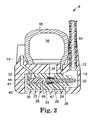
- FIG. 2is a side-sectional view of a penile pump in a state of equilibrium, having a termination chamber which can force the cylinder poppet against a valve seat during an overpressurization situation.
- FIG. 3is a side-sectional view of the penile pump shown in FIG. 2 during an overpressurization situation.
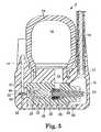
- FIG. 5is a side-sectional view of a penile pump having a diaphragm between the bypass passageway and the cylinder poppet output.
- FIG. 6is a side-sectional view of a penile pump having a bypass passageway which compresses a collapsible portion of the fluid output.
- FIG. 7is a side-sectional view of a penile pump having a bypass fluid passageway and a return fluid passageway with a check valve located in each.
- FIG. 8is a side-sectional view of a penile pump having a bypass fluid passageway and a return fluid passageway with a check valve located in each and a fluid resistor located within the return fluid passageway.
- FIG. 9is a side sectional view of a penile pump having a bypass fluid passageway and a return fluid passageway with a check valve located in the bypass fluid passageway and a pair of fluid resistors located within the return fluid passageway.
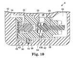
- FIG. 10is a side sectional view of a penile pump having a bypass fluid passageway with a pair of fluid resistors and a bypass channel with a check valve.
- FIG. 11is a side-sectional view of a penile pump having a fluid output that has a reduced throat portion that is sealable during an overpressurization situation.
- pump assembly 8when pump assembly 8 is actuated, fluid is drawn from the reservoir through the pump assembly 8 and pumped into the cylinders. During the inflation process and until released by the user, the pump assembly 8 maintains the fluid pressure in the cylinders, thus keeping them in their inflated state. When deflation is desired, the user manipulates assembly 8 , permitting fluid to transfer out of the inflatable cylinders and into the reservoir, thereby deflating the cylinders and returning them to a flaccid state.
- Pump assembly 8generally includes a housing 12 usually formed of silicone. Attached to housing 12 is a pump bulb 18 , which includes a relatively large pump chamber 36 . Fluid input 10 is coupled to the housing 12 and empties into an input chamber 16 . As such, fluid input 10 couples input chamber 16 to the reservoir. A common passageway 33 is fluidly coupled between input chamber 16 at one end of the housing 12 , and fluid output 14 at an opposite end of the housing 12 . Similarly, the pump chamber 36 is fluidly coupled to the common passageway 33 via pump passageway 34 .
- a reservoir poppet 20Disposed within common passageway 33 is a reservoir poppet 20 which functions as a check valve.
- Reservoir poppet 20is an elongated member having a contoured portion which abuts reservoir poppet valve seat 24 forming a fluid tight seal.
- a reservoir poppet spring 28engages reservoir poppet 20 and biases reservoir poppet 20 against the reservoir poppet valve seat 24 .
- cylinder poppet 22Also disposed within common passageway 33 and in line with reservoir poppet 20 is cylinder poppet 22 . Cylinder poppet 22 forms a second check valve within common passageway 33 . Cylinder poppet 22 is biased by cylinder poppet spring 30 against cylinder poppet valve seat 26 in a normal state, thereby forming another fluid tight seal within common passageway 33 .
- the pressurized fluidis allowed to pass through a portion of the common passageway 33 and into fluid output 14 , where it eventually reaches an inflatable cylinder.
- the pump bulb 18expands back to its original configuration, creating negative pressure within pump chamber 36 and common passageway 33 .
- This negative pressuredraws cylinder poppet 22 towards valve seat 26 and simultaneously pulls reservoir poppet 20 away from valve seat 24 .
- reservoir poppet spring 28causes the reservoir poppet 20 to reseat itself against valve seat 24 .
- pump bulb 18Repeated compression of pump bulb 18 eventually inflates the cylinders to a sufficient degree of rigidity for the user. Once inflated, the fluid remaining in fluid output 14 is under a relatively high degree of pressure. This high pressure fluid aids cylinder poppet spring 30 in forcing cylinder poppet 22 against cylinder poppet valve seat 26 again forming a fluid tight seal and preventing fluid from within the cylinders from passing back through the pump assembly 8 (preventing deflation of the cylinders).
- pump assembly 8(as shown in FIG. 1 ) works relatively well under normal circumstances.
- the pressure generatedmay be sufficient to remove reservoir poppet 20 and cylinder poppet 22 from their respective valve seats 24 and 26 , thus spontaneously inflating the cylinders.
- sufficient forceis generated against the reservoir (or a similar component) to cause the fluid pressure to exceed the resistive characteristics of poppets 20 or 22 (overcome the force of reservoir poppet spring 28 and cylinder poppet spring 30 ) to cause the fluid pressure to exceed the resistive characteristics of poppets 20 or 22 (overcome the force of reservoir poppet spring 28 and cylinder poppet spring 30 ), an overpressure situation has occurred.
- the only way to release this spontaneous inflationis to manually release the check valves.
- an overpressure tolerant pump assembly 9is provided and including a bypass passageway 38 is added to the system which couples input chamber 16 to an expansion chamber 40 .
- the expansion chamber 40is provided adjacent to the rear end 44 of cylinder poppet 22 .
- the relatively thin portion of housing 12 that exists between common passageway 33 and expansion chamber 40forms an abutting wall 42 .
- Abutting wall 42is relatively flexible and operates very similarly to a flexible diaphragm.
- planar surface area of abutting wall 42is greater than the area of nose 46 of cylinder poppet 22 (wherein the nose 46 is that portion of cylinder poppet 22 that would be exposed to overpressure generated by the reservoir when the cylinder poppet 22 is seated against the valve seat 26 ).
- This “nose” areais approximately equal to the cross sectional area of the common passageway 33 , at a point between the nose 46 and the rear end portion 47 of reservoir poppet 20 .
- the pressure generated by compression of the pump bulb 18is sufficient to overcome the force generated by abutting wall 42 , and allow fluid to move into the cylinders via fluid output 14 .
- reservoir poppet 20will be pulled away from its valve seat 24 and fluid will be drawn from bypass passageway 38 and fluid input 10 into pump chamber 36 .
- the termination chamber 40to return to its original state.
- bypass passageway 38is fluidly coupled at one end to the input chamber 16 .
- An expansion chamber 49 and a junction chamber 48are provided at the opposite end of bypass passageway 38 .
- Cylinder poppet output 32(which is coupled with common passageway 33 ) is fluidly coupled to junction chamber 48 .
- fluid output 14is also fluidly coupled to junction chamber 48 .
- Disposed between junction chamber 48 and expansion chamber 49is a flexible diaphragm 50 .
- flexible diaphragmis in the state represented by dashed lines. That is, flexible diaphragm 50 is flush against bypass passageway 38 .
- the pressurized fluid from the pump bulb 18is forced through common passageway 33 , bypassing cylinder poppet 22 and exiting through cylinder poppet output 32 into fluid output 14 , unhindered by flexible diaphragm 50 .
- expansion chamber 49is relatively large compared to cylinder poppet output 32 . More specifically, once the flexible diaphragm 50 is in the position represented by solid lines, a larger surface area of the flexible diaphragm 50 will then be exposed to the expansion chamber 49 than is exposed to the cylinder poppet output 32 . As such, with equal fluid pressure being generated in the bypass passageway 38 , and the cylinder poppet output 32 , a greater force will be exerted in the direction forcing flexible diaphragm 50 against cylinder poppet outlet 32 , due to the relative surface area ratios. When the user wishes to manually inflate the cylinder, a compression of the pump bulb 18 will generate force in excess of that exerted on flexible diaphragm 50 through bypass passageway 38 .
- FIG. 5illustrates a variation of the embodiment illustrated in FIG. 4 .
- the flexible diaphragm 50flexes between sealing the bypass passageway 38 and sealing the fluid output 14 . Sealing the fluid output 14 effectively prevents fluid from exiting cylinder poppet output 32 and entering fluid output 14 .
- FIG. 7illustrates a fourth embodiment of the present invention.
- This embodimenthas several elements that are in common with the previously described embodiments. Namely input chamber 16 is fluidly coupled to fluid output 14 via common passageway 33 .
- Common passageway 33is impeded by a reservoir poppet 20 and cylinder poppet 22 which are both spring biased to seat against their respective openings.
- the area between the nose of cylinder poppet 22 and the rear portion of reservoir poppet 20is referred to as intermediate chamber 62 .
- the intermediate chamber 62is fluidly coupled to a return channel 65 which is in fluid communication with expansion chamber 40 .
- a return check valve 75is provided within return channel 65 and only allows fluid flow from expansion chamber 40 to intermediate chamber 62 .
- a bypass channel 60is provided and fluidly couples input chamber 16 to return channel 65 . As indicated the junction between the bypass channel 60 and return channel 65 occurs between expansion chamber 40 and return check valve 75 .
- a bypass check valve 70is provided within bypass channel 60 and only allows fluid flow in the direction from input chamber 16 to expansion chamber 40 .
- intermediate chamber 62fluid pressure levels within intermediate chamber 62 are only reduced when pump bulb 18 is actuated forcing cylinder poppet 22 to unseat itself and causing the cylinders to be inflated.
- housing 12could be engaged in the manner described above to deflate the cylinders. That is manually actuating reservoir poppet 20 to disengage cylinder poppet 22 . The release of reservoir poppet 20 would allow pressurized fluid within intermediate chamber 62 to reenter input chamber 16 .
- a fifth embodiment of the present inventionis illustrated in FIG. 8.
- a return channel 65is provided which fluidly couples input chamber 16 to expansion chamber 40 .
- Intermediate chamber 62is fluidly coupled to return channel 65 via intermediate chamber passageway 64 .
- Located within return channel 65are a return check valve 75 and a fluid resistor 80 .
- Return check valve 75is positioned between intermediate chamber passageway 64 and expansion chamber 40 while fluid resistor 80 is positioned between intermediate chamber passageway 64 and input chamber 16 .
- Bypass channel 60is provided and fluidly couples input chamber 16 with return channel 65 wherein the junction between bypass channel 60 and return channel 65 occurs between the return check valve 75 and expansion chamber 40 .
- Located within bypass channel 60is a bypass check valve 70 that only allows fluid flow in the direction from input chamber 16 to expansion chamber 40 .
- Return check valve 75allows fluid flow from the direction of expansion chamber 40 towards both intermediate chamber 62 and input chamber 16 .
- bypass check valve 70As fluid pressures within input chamber 16 increase bypass check valve 70 is caused to be unseated allowing fluid flow into expansion chamber 40 as previously described.
- the cracking pressure required to unseat bypass check valve 70is lower than that required to unseat reservoir poppet 20 .
- pressurized fluidis caused to flow from input chamber 16 through bypass channel 60 and into expansion chamber 40 , and if sufficient pressures are reached return check valve 75 can be unseated and pressurized fluid can enter intermediate chamber 62 .
- abutting wall 42is caused to deflect which in turn causes cylinder poppet 22 to firmly seal preventing spontaneous inflation.
- input chamber 16is in fluid communication with return channel 65 .
- fluid resistor 80is positioned between input chamber 16 and intermediate chamber 62 .
- Fluid resistor 80is a narrowing of a fluid passageway restricting fluid flow, a lengthening of the fluid path, or a combination of the two.
- Fluid resistor 80could be a separate component added to the structure, rather than a modification of the existing passageway.
- fluid flow from input chamber 16 into intermediate chamber 62 through fluid resistor 80is trivial.
- fluid resistor 80will allow a small amount of bleed through into input chamber 16 . This has a very negligible effect on pumping.
- pressure levels within expansion chamber 40 and intermediate chamber 62can each reach relatively high levels.
- Return check valve 75will only allow pressurized fluid within expansion chamber 40 to exit when pressure levels within intermediate chamber 62 and the corresponding portion of return channel 65 are lower than that within expansion chamber 40 .
- fluid resistor 80slowly allows pressurized fluid within intermediate chamber 62 to bleed back into input chamber 16 .
- pressure levels within intermediate chamber 62 and input chamber 16will reach stasis. As pressure levels within intermediate chamber 62 are reduced, higher pressure fluid from expansion chamber 40 will unseat return check valve 75 and also eventually pass through fluid resistor 80 back into input chamber 16 returning the entire system to equilibrium.
- a sixth embodimentis shown with reference to FIG. 9.
- a return channel 65is provided and fluidly couples input chamber 16 to expansion chamber 40 .
- Intermediate chamber 62is also fluidly coupled to return channel 65 via intermediate chamber passageway 64 .
- Located between input chamber 16 and intermediate chamber passageway 64is a reservoir side fluid resistor 90 .
- Located between intermediate chamber passageway 64 and expansion chamber 40is a cylinder side fluid resistor 85 .
- Bypass channel 60is provided and fluidly couples input chamber 16 to expansion chamber 40 , effectively bypassing both fluid resistors 85 and 90 .
- Bypass check valve 70is provided within bypass channel 60 and allows fluid flow in the direction from input chamber 16 to expansion chamber 40 .
- bypass check valve 70has a lower cracking pressure than reservoir poppet 20 encouraging fluid flow through bypass channel 60 and into expansion chamber 40 prior to unseating reservoir poppet 20 and allowing pressurized fluid to flow into intermediate chamber 62 . While return channel 65 is in fluid communication with both intermediate chamber 62 and expansion chamber 40 , initially pressurized fluid from reservoir 16 will not quickly enter either of these two areas through return channel 65 due to restricted fluid flow through cylinder side fluid resistor 85 and reservoir side fluid resistor 90 .
- a bypass fluid passageway 38fluidly couples input chamber 16 to expansion chamber 40 .
- Located within bypass passageway 38is a high impedance fluid resistor 95
- Intermediate chamber passageway 64fluidly couples intermediate chamber 62 to bypass passageway 38 .
- Located within intermediate chamber passageway 64is a low impedance fluid resistor 100 It is to be understood that with reference to fluid resistors 95 and 100 the terms high and low are with respect to one another. That is fluid resistor 100 has a lower fluid impedance than fluid resistor 95 . In other words, a higher volume of fluid will travel through low impedance resistor 100 than through high impedance resistor 95 in the same amount of time when under the same pressure.
- Bypass channel 60is provided and is coupled to bypass passageway 38 , effectively bypassing the high impedance fluid resistor 95 .
- Bypass check valve 70is located within bypass channel 60 and only allows fluid flow in the direction from the input chamber 16 to expansion chamber 40 .
- the cracking pressure of bypass check valve 70is set such that when an over-pressurization situation occurs the path of least resistance from input chamber 16 is to enter bypass passageway 38 , open bypass check valve 70 , and enter expansion chamber 40 .
- Pressurized fluidmay eventually be able to unseat reservoir poppet 20 or flow through low impedance resistor 100 and enter intermediate chamber 62 .
- the abutting wall 42is displaced by the movement of expansion chamber 40 under increased fluid pressures causing cylinder poppet 22 to seal tightly preventing spontaneous inflation.
- intermediate chamber 62empties at a faster rate.
- fluidwill only travel from expansion chamber 40 through high impedance resistor 95 when fluid pressure levels within bypass passageway 38 adjacent input chamber 16 are sufficiently low. That is, lower than that within expansion chamber 40 .
- This factcoupled with the ability of the intermediate chamber 62 to reduce pressure levels more quickly will always assure that pressure levels within expansion chamber 40 are higher than that within intermediate chamber 62 once again preventing spontaneous inflation.
- a small amount of pressurized fluidwill pass through low impedance resistor 100 , however the effect will be negligible.
- FIG. 11represents an eighth embodiment of the present invention.
- housing 12has been slightly modified to accommodate a variety of additional internal passageways.
- Fluid input 10is coupled with a reservoir at one end and reservoir chamber 16 at the other.
- overpressure chamber 156Located within housing 12 , and coupled to fluid input 10 prior to reservoir chamber 16 , is an overpressure chamber 156 .
- overpressure chamber 156has an overpressure chamber input 158 having a narrowed opening.
- Cylinder poppet output 32leads into an output passageway 160 .
- Output passageway 160leads to a first output chamber 162 and a second output chamber 164 (actually two parts of a single chamber or passage way).
- the fluid output 14is fluidly coupled to the first output chamber 162 .
- FIG. 12a ninth embodiment to the present invention is illustrated.
- This embodimentcan be used as shown or can be coupled with any of the previously described embodiments.
- the housing 12 of the valve assemblywill be made of a flexible material such as silicone.
- a rigid insertis incorporated into housing 12 to eliminate this degree of flexibility.
- a solid cylindrical element 105is incorporated within housing 12 and surrounds reservoir poppet 20 and cylinder poppet 22 .
- housing 12will be unable to displace reservoir poppet 20 or cylinder poppet 22 .
- the usermust be able to manually displace reservoir poppet 20 by compressing the side walls of housing 12 and this function is maintained.
- housing 12 for the valve assemblyis generally molded, it may be desirable to have cylindrical element 105 in place during the fabrication process by including a plurality of holes 110 in cylindrical element 105 and placing cylindrical element 105 in the mold during fabrication. Cylindrical element 105 will in effect be molded in place and holes 110 allow the material being utilized (i.e. silicone) to flow through cylindrical element 105 and properly define housing 12 . While shown as being cylindrical, element 105 can be formed into any appropriate shape for the valve assembly being utilized.
- the present inventionutilizes an outlet sealing mechanism that relies on the overpressure generated by a compression of the reservoir (or similar component) to also seal the output. That is, the overpressure generated is effectively used against itself to prevent fluid from entering the cylinder and producing a spontaneous inflation. While various embodiments have been shown and described which utilize this effect, it is to be understood that any such utilization of the overpressure to prevent fluid flow to the cylinders is within the scope and spirit of the present invention, and as such, the present invention is not intended to be limited only to those specific embodiments shown and described herein.
Landscapes
- Health & Medical Sciences (AREA)
- Engineering & Computer Science (AREA)
- Vascular Medicine (AREA)
- Life Sciences & Earth Sciences (AREA)
- Transplantation (AREA)
- Cardiology (AREA)
- Biomedical Technology (AREA)
- Heart & Thoracic Surgery (AREA)
- Reproductive Health (AREA)
- Oral & Maxillofacial Surgery (AREA)
- Animal Behavior & Ethology (AREA)
- General Health & Medical Sciences (AREA)
- Public Health (AREA)
- Veterinary Medicine (AREA)
- General Engineering & Computer Science (AREA)
- Mechanical Engineering (AREA)
- Prostheses (AREA)
- Check Valves (AREA)
Abstract
Description
Claims (33)
Priority Applications (2)
| Application Number | Priority Date | Filing Date | Title |
|---|---|---|---|
| US10/313,251US6935847B2 (en) | 2000-12-27 | 2002-12-06 | Spontaneous inflation inhibitor for inflatable prosthesis |
| US11/186,224US7350538B2 (en) | 2000-12-27 | 2005-07-21 | Method of preventing inadvertent inflation of an inflatable prosthesis |
Applications Claiming Priority (2)
| Application Number | Priority Date | Filing Date | Title |
|---|---|---|---|
| US09/749,256US6533719B2 (en) | 2000-12-27 | 2000-12-27 | Diaphragm based spontaneous inflation inhibitor in a pump for an inflatable prosthesis |
| US10/313,251US6935847B2 (en) | 2000-12-27 | 2002-12-06 | Spontaneous inflation inhibitor for inflatable prosthesis |
Related Parent Applications (1)
| Application Number | Title | Priority Date | Filing Date |
|---|---|---|---|
| US09/749,256DivisionUS6533719B2 (en) | 2000-12-27 | 2000-12-27 | Diaphragm based spontaneous inflation inhibitor in a pump for an inflatable prosthesis |
Related Child Applications (1)
| Application Number | Title | Priority Date | Filing Date |
|---|---|---|---|
| US11/186,224DivisionUS7350538B2 (en) | 2000-12-27 | 2005-07-21 | Method of preventing inadvertent inflation of an inflatable prosthesis |
Publications (2)
| Publication Number | Publication Date |
|---|---|
| US20030065249A1 US20030065249A1 (en) | 2003-04-03 |
| US6935847B2true US6935847B2 (en) | 2005-08-30 |
Family
ID=25012961
Family Applications (3)
| Application Number | Title | Priority Date | Filing Date |
|---|---|---|---|
| US09/749,256Expired - LifetimeUS6533719B2 (en) | 2000-12-27 | 2000-12-27 | Diaphragm based spontaneous inflation inhibitor in a pump for an inflatable prosthesis |
| US10/313,251Expired - LifetimeUS6935847B2 (en) | 2000-12-27 | 2002-12-06 | Spontaneous inflation inhibitor for inflatable prosthesis |
| US11/186,224Expired - LifetimeUS7350538B2 (en) | 2000-12-27 | 2005-07-21 | Method of preventing inadvertent inflation of an inflatable prosthesis |
Family Applications Before (1)
| Application Number | Title | Priority Date | Filing Date |
|---|---|---|---|
| US09/749,256Expired - LifetimeUS6533719B2 (en) | 2000-12-27 | 2000-12-27 | Diaphragm based spontaneous inflation inhibitor in a pump for an inflatable prosthesis |
Family Applications After (1)
| Application Number | Title | Priority Date | Filing Date |
|---|---|---|---|
| US11/186,224Expired - LifetimeUS7350538B2 (en) | 2000-12-27 | 2005-07-21 | Method of preventing inadvertent inflation of an inflatable prosthesis |
Country Status (1)
| Country | Link |
|---|---|
| US (3) | US6533719B2 (en) |
Cited By (27)
| Publication number | Priority date | Publication date | Assignee | Title |
|---|---|---|---|---|
| US20050250981A1 (en)* | 2000-12-27 | 2005-11-10 | Kuyava Charles C | Method of preventing inadvertent inflation of an inflatable prosthesis |
| US20060182637A1 (en)* | 2005-02-16 | 2006-08-17 | Sarcos Investments Lc. | Method and apparatus for reducing free flow risk |
| US20070142700A1 (en)* | 2005-12-19 | 2007-06-21 | Fogarty Terence M | Pump with one-touch release |
| US20090132043A1 (en)* | 2007-11-15 | 2009-05-21 | George Stephanie A | Prosthesis with Bladder that Adjusts Girth |
| US20100082057A1 (en)* | 2008-09-30 | 2010-04-01 | Borkon William D | Variable rigidity vaginal dilator and use thereof |
| US20100160722A1 (en)* | 2008-12-23 | 2010-06-24 | Ams Research Corporation | Penile prosthesis implantation device |
| US20110118540A1 (en)* | 2009-11-16 | 2011-05-19 | Coloplast A/S | Penile prosthetic with anti-autoinflation mechanism |
| US7946975B2 (en) | 2005-04-08 | 2011-05-24 | Ams Research Corporation | Fluid reservoir for penile implant devices |
| US20110190577A1 (en)* | 2010-02-03 | 2011-08-04 | Coloplast A/S | Inflatable penile implant |
| US20110190576A1 (en)* | 2010-02-04 | 2011-08-04 | Coloplast A/S | Inflatable penile implant |
| US8109870B2 (en) | 2006-11-10 | 2012-02-07 | Ams Research Corporation | Inflatable penile prosthesis bypass valve noise reduction |
| US8114011B2 (en) | 2007-10-23 | 2012-02-14 | Ams Research Corporation | Corrugated inflatable penile prosthesis cylinder |
| US8123674B2 (en) | 2007-11-12 | 2012-02-28 | Ams Research Corporation | Corrugated expansion-constraining sleeve for an inflatable penile prosthesis cylinder |
| US8257246B1 (en) | 2011-04-19 | 2012-09-04 | Coloplast A/S | Penile prosthetic system and pump having inlet valve with high velocity closure mechanism |
| US8276591B2 (en) | 2000-12-27 | 2012-10-02 | Ams Research Corporation | Diaphragm based spontaneous inflation inhibitor in a pump for an inflatable prosthesis |
| US8911350B2 (en) | 2007-10-23 | 2014-12-16 | Ams Research Corporation | Malleable prosthesis with enhanced concealability |
| US9084678B2 (en) | 2012-01-20 | 2015-07-21 | Ams Research Corporation | Automated implantable penile prosthesis pump system |
| US9089426B2 (en) | 2012-03-21 | 2015-07-28 | Ams Research Corporation | Automated implantable penile prosthesis pump system |
| US9101474B2 (en) | 2012-05-31 | 2015-08-11 | Ams Research Corporation | Implantable penile prosthesis |
| US9474610B2 (en) | 2010-12-21 | 2016-10-25 | Boston Scientific Scimed, Inc. | Adjustable length rear tip extender for penile prosthesis |
| US9554937B2 (en) | 2014-06-16 | 2017-01-31 | Coloplast A/S | Penile prosthetic pump having an inlet valve with a lockout flange |
| US9649217B2 (en) | 2014-07-08 | 2017-05-16 | Coloplast A/S | Implantable penile prosthetic lockout valve assembly |
| US9987136B2 (en) | 2016-09-09 | 2018-06-05 | Coloplast A/S | Penile prosthetic pump with an inflation assembly including a rotary valve |
| US10646344B2 (en) | 2016-08-11 | 2020-05-12 | Boston Scientific Scimed, Inc. | Inflatable penile prosthesis with four-way valve pump |
| US10952855B2 (en) | 2016-03-24 | 2021-03-23 | Boston Scientific Scimed, Inc. | Inflatable penile prosthesis with reversible flow pump assembly |
| US11311382B2 (en) | 2018-11-27 | 2022-04-26 | Boston Scientific Scimed, Inc. | Pump assembly having a push valve for a penile prosthesis |
| US12083016B2 (en) | 2020-10-15 | 2024-09-10 | Boston Scientific Scimed, Inc. | Pump assembly for a penile prosthesis |
Families Citing this family (36)
| Publication number | Priority date | Publication date | Assignee | Title |
|---|---|---|---|---|
| US6723042B2 (en)* | 2000-12-27 | 2004-04-20 | Ams Research Corporation | Penile pump with side release mechanism |
| US6929599B2 (en)* | 2002-05-14 | 2005-08-16 | Ams Research Corporation | Implantable penile prosthesis fluid transfer systems and methods |
| US6991601B2 (en)* | 2002-12-02 | 2006-01-31 | Ams Research Corporation | Implantable pump |
| US7244227B2 (en)* | 2003-03-10 | 2007-07-17 | Ams Research Corporation | Implantable penile prosthesis pump |
| US6808490B1 (en)* | 2003-04-25 | 2004-10-26 | Ams Research Corporation | Penile prosthesis with improved tubing junction |
| AU2004279393B2 (en)* | 2003-10-02 | 2010-04-22 | Ams Research Corporation | Implantable penile prosthesis pump |
| US7351198B2 (en)* | 2004-06-02 | 2008-04-01 | Ethicon Endo-Surgery, Inc. | Implantable adjustable sphincter system |
| CA2590051C (en) | 2004-12-17 | 2013-11-19 | Ams Research Corporation | Implantable penile prosthesis pump |
| US7775966B2 (en) | 2005-02-24 | 2010-08-17 | Ethicon Endo-Surgery, Inc. | Non-invasive pressure measurement in a fluid adjustable restrictive device |
| US8066629B2 (en) | 2005-02-24 | 2011-11-29 | Ethicon Endo-Surgery, Inc. | Apparatus for adjustment and sensing of gastric band pressure |
| US7699770B2 (en) | 2005-02-24 | 2010-04-20 | Ethicon Endo-Surgery, Inc. | Device for non-invasive measurement of fluid pressure in an adjustable restriction device |
| US7775215B2 (en) | 2005-02-24 | 2010-08-17 | Ethicon Endo-Surgery, Inc. | System and method for determining implanted device positioning and obtaining pressure data |
| US7927270B2 (en) | 2005-02-24 | 2011-04-19 | Ethicon Endo-Surgery, Inc. | External mechanical pressure sensor for gastric band pressure measurements |
| US7658196B2 (en) | 2005-02-24 | 2010-02-09 | Ethicon Endo-Surgery, Inc. | System and method for determining implanted device orientation |
| US8016744B2 (en) | 2005-02-24 | 2011-09-13 | Ethicon Endo-Surgery, Inc. | External pressure-based gastric band adjustment system and method |
| US8870742B2 (en) | 2006-04-06 | 2014-10-28 | Ethicon Endo-Surgery, Inc. | GUI for an implantable restriction device and a data logger |
| US8152710B2 (en) | 2006-04-06 | 2012-04-10 | Ethicon Endo-Surgery, Inc. | Physiological parameter analysis for an implantable restriction device and a data logger |
| US8187163B2 (en) | 2007-12-10 | 2012-05-29 | Ethicon Endo-Surgery, Inc. | Methods for implanting a gastric restriction device |
| US8100870B2 (en) | 2007-12-14 | 2012-01-24 | Ethicon Endo-Surgery, Inc. | Adjustable height gastric restriction devices and methods |
| US8142452B2 (en) | 2007-12-27 | 2012-03-27 | Ethicon Endo-Surgery, Inc. | Controlling pressure in adjustable restriction devices |
| US8377079B2 (en) | 2007-12-27 | 2013-02-19 | Ethicon Endo-Surgery, Inc. | Constant force mechanisms for regulating restriction devices |
| US8192350B2 (en) | 2008-01-28 | 2012-06-05 | Ethicon Endo-Surgery, Inc. | Methods and devices for measuring impedance in a gastric restriction system |
| US8337389B2 (en) | 2008-01-28 | 2012-12-25 | Ethicon Endo-Surgery, Inc. | Methods and devices for diagnosing performance of a gastric restriction system |
| US8591395B2 (en) | 2008-01-28 | 2013-11-26 | Ethicon Endo-Surgery, Inc. | Gastric restriction device data handling devices and methods |
| US7844342B2 (en) | 2008-02-07 | 2010-11-30 | Ethicon Endo-Surgery, Inc. | Powering implantable restriction systems using light |
| US8221439B2 (en) | 2008-02-07 | 2012-07-17 | Ethicon Endo-Surgery, Inc. | Powering implantable restriction systems using kinetic motion |
| US8114345B2 (en) | 2008-02-08 | 2012-02-14 | Ethicon Endo-Surgery, Inc. | System and method of sterilizing an implantable medical device |
| US8591532B2 (en) | 2008-02-12 | 2013-11-26 | Ethicon Endo-Sugery, Inc. | Automatically adjusting band system |
| US8057492B2 (en) | 2008-02-12 | 2011-11-15 | Ethicon Endo-Surgery, Inc. | Automatically adjusting band system with MEMS pump |
| US20090209995A1 (en)* | 2008-02-14 | 2009-08-20 | Byrum Randal T | Implantable adjustable sphincter system |
| US8034065B2 (en) | 2008-02-26 | 2011-10-11 | Ethicon Endo-Surgery, Inc. | Controlling pressure in adjustable restriction devices |
| US8233995B2 (en) | 2008-03-06 | 2012-07-31 | Ethicon Endo-Surgery, Inc. | System and method of aligning an implantable antenna |
| US8187162B2 (en) | 2008-03-06 | 2012-05-29 | Ethicon Endo-Surgery, Inc. | Reorientation port |
| US8702589B2 (en)* | 2008-12-23 | 2014-04-22 | Ams Research Corporation | System to transport components of implantable penile prostheses |
| US8241203B2 (en)* | 2010-02-12 | 2012-08-14 | Fogarty Terence M | Inflatable penile prosthesis with spool valve |
| WO2025072285A1 (en)* | 2023-09-29 | 2025-04-03 | Boston Scientific Scimed, Inc. | Pump overpressure relief feature for a penile prosthesis |
Citations (61)
| Publication number | Priority date | Publication date | Assignee | Title |
|---|---|---|---|---|
| US988120A (en) | 1910-02-15 | 1911-03-28 | John B Lott | Dilator. |
| US1863057A (en) | 1930-03-03 | 1932-06-14 | George A Innes | Surgical drain |
| US3312215A (en) | 1963-08-02 | 1967-04-04 | Max N Silber | Uterocervical cannula |
| US3344791A (en) | 1965-02-12 | 1967-10-03 | John W Foderick | Bulbous urinary catheter with axial extension means |
| US3397699A (en) | 1966-05-05 | 1968-08-20 | Gerald C. Kohl | Retaining catheter having resiliently biased wing flanges |
| US3503400A (en) | 1967-07-12 | 1970-03-31 | Sven M Osthagen | Urethral valve |
| US3642004A (en) | 1970-01-05 | 1972-02-15 | Life Support Equipment Corp | Urethral valve |
| US3731670A (en) | 1971-05-03 | 1973-05-08 | David Roy Pressman | Corporeal fluid control using bistable magnetic duct valve |
| US3797478A (en) | 1972-07-11 | 1974-03-19 | M Walsh | Multi-functional valve for use in the urethra |
| US3812841A (en) | 1972-08-21 | 1974-05-28 | L Isaacson | Urethra magnetic valve structure |
| US3873063A (en)* | 1973-11-01 | 1975-03-25 | Kieley & Mueller | Aspirated balance piston |
| US3954102A (en) | 1974-07-19 | 1976-05-04 | American Medical Systems, Inc. | Penile erection system and methods of implanting and using same |
| DE2537506A1 (en) | 1975-08-22 | 1977-03-03 | Hennig Gerhard | Bladder outlet valve for incontinent people - has magnet cone embedded in magnet ring seat with powerful external opening magnet |
| US4222377A (en) | 1977-06-27 | 1980-09-16 | American Medical Systems, Inc. | Pressure regulated artificial sphincter systems |
| US4267829A (en) | 1979-04-11 | 1981-05-19 | American Medical Systems, Inc. | Penile prosthesis |
| US4344434A (en) | 1981-06-01 | 1982-08-17 | Santa Barbara Medical Foundation Clinic | Ileostomy appliance and method for implanting the same |
| US4407278A (en) | 1981-05-15 | 1983-10-04 | American Medical Systems, Inc. | Penile prosthesis with improved fluid control |
| US4412530A (en) | 1981-09-21 | 1983-11-01 | American Medical Systems, Inc. | Dual-mode valve pressure regulating system |
| US4441491A (en)* | 1982-08-13 | 1984-04-10 | Evans Sr Alvin S | Pressure relief valve system for penile implant device |
| US4453536A (en) | 1980-11-03 | 1984-06-12 | Abild Robert N | Body channel occluder |
| US4489732A (en) | 1982-09-20 | 1984-12-25 | Hasson Harrith M | Gynecological instrument |
| US4537183A (en) | 1983-04-08 | 1985-08-27 | Mentor Corporation | Connector device for connecting elastic tubing of an implantable device |
| US4553959A (en) | 1982-01-27 | 1985-11-19 | The Victoria University Of Manchester | Urethral catheter |
| US4566446A (en) | 1983-04-08 | 1986-01-28 | Mentor Corporation | Penile prosthesis device |
| US4571241A (en) | 1983-12-16 | 1986-02-18 | Christopher T Graham | Urinary catheter with collapsible urethral tube |
| US4590927A (en)* | 1985-02-25 | 1986-05-27 | American Medical Systems, Inc. | Unitary, inflatable penile prosthesis system |
| US4632435A (en) | 1984-12-27 | 1986-12-30 | American Medical Systems, Inc. | Tubing connector system |
| US4671261A (en) | 1986-01-24 | 1987-06-09 | Fischell Robert | Penile erection device with valving in the penile cylinder |
| US4682583A (en) | 1984-04-13 | 1987-07-28 | Burton John H | Inflatable artificial sphincter |
| US4697619A (en)* | 1982-04-07 | 1987-10-06 | Sulzer Brothers Limited | Solenoid valve having a power amplifier |
| US4710169A (en) | 1983-12-16 | 1987-12-01 | Christopher T Graham | Urinary catheter with collapsible urethral tube |
| US4718410A (en) | 1978-08-02 | 1988-01-12 | Hakky Said I | Surgical implants |
| US4782826A (en) | 1987-05-21 | 1988-11-08 | Mentor Corporation | Penile prosthesis |
| US4850963A (en) | 1986-06-11 | 1989-07-25 | Utah Bioresearch, Inc. | Apparatus and methods for achieving urinary continence |
| US4932938A (en) | 1989-05-05 | 1990-06-12 | Medical Engineering Corporation | Urethral indwelling catheter with incontinence control |
| US4944732A (en) | 1988-08-15 | 1990-07-31 | Sandoz Nutrition Corporation | Gastrostomy feeding port |
| US4958630A (en) | 1989-10-06 | 1990-09-25 | Advanced Surgical Intervention, Inc. | Method and apparatus for treating impotence |
| US4968294A (en) | 1989-02-09 | 1990-11-06 | Salama Fouad A | Urinary control valve and method of using same |
| US5030199A (en) | 1989-12-11 | 1991-07-09 | Medical Engineering Corporation | Female incontinence control device with magnetically operable valve and method |
| US5034009A (en) | 1987-11-03 | 1991-07-23 | Mouchel Jack A P | Instrument for locating the proximal end of the urethra |
| US5041092A (en) | 1989-08-29 | 1991-08-20 | Medical Engineering Corporation | Urethral indwelling catheter with magnetically controlled drainage valve and method |
| US5048510A (en) | 1988-08-29 | 1991-09-17 | American Medical Systems, Inc. | Inflatable penile prosthesis with satellite reservoir |
| US5048511A (en) | 1989-10-06 | 1991-09-17 | Advanced Surgical Intervention, Inc. | Method and apparatus for treating impotence |
| US5062417A (en) | 1990-10-10 | 1991-11-05 | Mentor Corporation | Prosthesis with improved pump |
| US5063914A (en) | 1990-05-30 | 1991-11-12 | Mentor Corporation | Penile prosthesis |
| US5074849A (en) | 1990-01-22 | 1991-12-24 | Sachse Hans Ernst | Ureter drainage tube with fixable auxiliary tube |
| US5085650A (en) | 1989-10-20 | 1992-02-04 | Giglio Frank A | Gynecological urethral suppository |
| US5088980A (en) | 1990-05-31 | 1992-02-18 | The United States Of America As Represented By The Department Of Health And Human Services | Intra-urethral valve with integral spring |
| US5090424A (en) | 1990-12-31 | 1992-02-25 | Uromed Corporation | Conformable urethral plug |
| US5112295A (en) | 1990-04-20 | 1992-05-12 | Zinner Norman R | Penile prosthesis and method |
| US5114398A (en) | 1990-02-27 | 1992-05-19 | Medical Engineering Corporation | Female incontinence control device with mechanically operable valve |
| US5131906A (en) | 1988-10-20 | 1992-07-21 | Chen Fusen H | Incontinence device |
| US5141509A (en)* | 1991-08-06 | 1992-08-25 | American Medical Systems, Inc. | Penile prosthesis having means for preventing spontaneous inflation |
| US5167611A (en) | 1991-07-22 | 1992-12-01 | Mentor Corporation | Penile implant with lengthening cylinder |
| US5171272A (en) | 1990-09-24 | 1992-12-15 | American Medical Systems, Inc. | Fluid pump for penile prosthesis |
| US5186180A (en) | 1989-08-07 | 1993-02-16 | Bellas Gabriel A S | Intra-vaginal prolapse diagnostic instrument |
| US5250020A (en) | 1991-09-12 | 1993-10-05 | Mentor Corporation | Unitary inflatable penile prosthesis |
| US5344388A (en) | 1991-05-01 | 1994-09-06 | Maxwell G Patrick | Textured surface prosthetic device |
| US5851176A (en)* | 1996-07-29 | 1998-12-22 | Mentor Corporation | Pressure-responsive lockout valve and method of use |
| US5895424A (en) | 1996-11-12 | 1999-04-20 | Mentor Corporation | Prosthesis having an alignment indicator and method of using same |
| US6533719B2 (en) | 2000-12-27 | 2003-03-18 | Ams Research Corporation | Diaphragm based spontaneous inflation inhibitor in a pump for an inflatable prosthesis |
Family Cites Families (7)
| Publication number | Priority date | Publication date | Assignee | Title |
|---|---|---|---|---|
| US2002451A (en)* | 1935-01-21 | 1935-05-21 | Wallace M Gray | Water hammer eliminator |
| US3487852A (en)* | 1967-03-28 | 1970-01-06 | Snap Tite Inc | Relief valve |
| US3565555A (en)* | 1969-08-04 | 1971-02-23 | Nippodenso Kk | Manual delivery pump |
| DE2700058C2 (en)* | 1977-01-03 | 1987-05-07 | Alfred Teves Gmbh, 6000 Frankfurt | Valve arrangement |
| DE3504789A1 (en)* | 1985-02-13 | 1986-08-14 | Webasto-Werk W. Baier GmbH & Co, 8035 Gauting | ELECTROMAGNETICALLY ACTUATED PISTON PUMP |
| US5037099A (en)* | 1990-03-08 | 1991-08-06 | Burtch Ronald P | Game device |
| US5950129A (en)* | 1996-12-09 | 1999-09-07 | Telefonaktiebolaget Lm Ericsson (Publ) | Two-way in-flight radio telecommunication system and method |
- 2000
- 2000-12-27USUS09/749,256patent/US6533719B2/ennot_activeExpired - Lifetime
- 2002
- 2002-12-06USUS10/313,251patent/US6935847B2/ennot_activeExpired - Lifetime
- 2005
- 2005-07-21USUS11/186,224patent/US7350538B2/ennot_activeExpired - Lifetime
Patent Citations (65)
| Publication number | Priority date | Publication date | Assignee | Title |
|---|---|---|---|---|
| US988120A (en) | 1910-02-15 | 1911-03-28 | John B Lott | Dilator. |
| US1863057A (en) | 1930-03-03 | 1932-06-14 | George A Innes | Surgical drain |
| US3312215A (en) | 1963-08-02 | 1967-04-04 | Max N Silber | Uterocervical cannula |
| US3344791A (en) | 1965-02-12 | 1967-10-03 | John W Foderick | Bulbous urinary catheter with axial extension means |
| US3397699A (en) | 1966-05-05 | 1968-08-20 | Gerald C. Kohl | Retaining catheter having resiliently biased wing flanges |
| US3503400A (en) | 1967-07-12 | 1970-03-31 | Sven M Osthagen | Urethral valve |
| US3642004A (en) | 1970-01-05 | 1972-02-15 | Life Support Equipment Corp | Urethral valve |
| US3731670A (en) | 1971-05-03 | 1973-05-08 | David Roy Pressman | Corporeal fluid control using bistable magnetic duct valve |
| US3797478A (en) | 1972-07-11 | 1974-03-19 | M Walsh | Multi-functional valve for use in the urethra |
| US3812841A (en) | 1972-08-21 | 1974-05-28 | L Isaacson | Urethra magnetic valve structure |
| US3873063A (en)* | 1973-11-01 | 1975-03-25 | Kieley & Mueller | Aspirated balance piston |
| US3954102A (en) | 1974-07-19 | 1976-05-04 | American Medical Systems, Inc. | Penile erection system and methods of implanting and using same |
| DE2537506A1 (en) | 1975-08-22 | 1977-03-03 | Hennig Gerhard | Bladder outlet valve for incontinent people - has magnet cone embedded in magnet ring seat with powerful external opening magnet |
| US4222377A (en) | 1977-06-27 | 1980-09-16 | American Medical Systems, Inc. | Pressure regulated artificial sphincter systems |
| US4718410A (en) | 1978-08-02 | 1988-01-12 | Hakky Said I | Surgical implants |
| US4267829A (en) | 1979-04-11 | 1981-05-19 | American Medical Systems, Inc. | Penile prosthesis |
| US4383525A (en) | 1979-12-28 | 1983-05-17 | American Medical Systems, Inc. | Implantable penile prosthetic cylinder with inclusive fluid reservoir |
| US5704895A (en) | 1979-12-28 | 1998-01-06 | American Medical Systems, Inc. | Implantable penile prosthetic cylinder with inclusive fluid reservoir |
| US4453536A (en) | 1980-11-03 | 1984-06-12 | Abild Robert N | Body channel occluder |
| US4407278A (en) | 1981-05-15 | 1983-10-04 | American Medical Systems, Inc. | Penile prosthesis with improved fluid control |
| US4344434A (en) | 1981-06-01 | 1982-08-17 | Santa Barbara Medical Foundation Clinic | Ileostomy appliance and method for implanting the same |
| US4412530A (en) | 1981-09-21 | 1983-11-01 | American Medical Systems, Inc. | Dual-mode valve pressure regulating system |
| US4553959A (en) | 1982-01-27 | 1985-11-19 | The Victoria University Of Manchester | Urethral catheter |
| US4697619A (en)* | 1982-04-07 | 1987-10-06 | Sulzer Brothers Limited | Solenoid valve having a power amplifier |
| US4441491A (en)* | 1982-08-13 | 1984-04-10 | Evans Sr Alvin S | Pressure relief valve system for penile implant device |
| US4489732A (en) | 1982-09-20 | 1984-12-25 | Hasson Harrith M | Gynecological instrument |
| US4537183A (en) | 1983-04-08 | 1985-08-27 | Mentor Corporation | Connector device for connecting elastic tubing of an implantable device |
| US4566446A (en) | 1983-04-08 | 1986-01-28 | Mentor Corporation | Penile prosthesis device |
| US4710169A (en) | 1983-12-16 | 1987-12-01 | Christopher T Graham | Urinary catheter with collapsible urethral tube |
| US4571241A (en) | 1983-12-16 | 1986-02-18 | Christopher T Graham | Urinary catheter with collapsible urethral tube |
| US4682583A (en) | 1984-04-13 | 1987-07-28 | Burton John H | Inflatable artificial sphincter |
| US4632435A (en) | 1984-12-27 | 1986-12-30 | American Medical Systems, Inc. | Tubing connector system |
| US4590927A (en)* | 1985-02-25 | 1986-05-27 | American Medical Systems, Inc. | Unitary, inflatable penile prosthesis system |
| US4671261A (en) | 1986-01-24 | 1987-06-09 | Fischell Robert | Penile erection device with valving in the penile cylinder |
| US4850963A (en) | 1986-06-11 | 1989-07-25 | Utah Bioresearch, Inc. | Apparatus and methods for achieving urinary continence |
| US4782826A (en) | 1987-05-21 | 1988-11-08 | Mentor Corporation | Penile prosthesis |
| US5034009A (en) | 1987-11-03 | 1991-07-23 | Mouchel Jack A P | Instrument for locating the proximal end of the urethra |
| US4944732A (en) | 1988-08-15 | 1990-07-31 | Sandoz Nutrition Corporation | Gastrostomy feeding port |
| US5048510A (en) | 1988-08-29 | 1991-09-17 | American Medical Systems, Inc. | Inflatable penile prosthesis with satellite reservoir |
| US5131906A (en) | 1988-10-20 | 1992-07-21 | Chen Fusen H | Incontinence device |
| US4968294A (en) | 1989-02-09 | 1990-11-06 | Salama Fouad A | Urinary control valve and method of using same |
| US4932938A (en) | 1989-05-05 | 1990-06-12 | Medical Engineering Corporation | Urethral indwelling catheter with incontinence control |
| US5186180A (en) | 1989-08-07 | 1993-02-16 | Bellas Gabriel A S | Intra-vaginal prolapse diagnostic instrument |
| US5041092A (en) | 1989-08-29 | 1991-08-20 | Medical Engineering Corporation | Urethral indwelling catheter with magnetically controlled drainage valve and method |
| US5048511A (en) | 1989-10-06 | 1991-09-17 | Advanced Surgical Intervention, Inc. | Method and apparatus for treating impotence |
| US4958630A (en) | 1989-10-06 | 1990-09-25 | Advanced Surgical Intervention, Inc. | Method and apparatus for treating impotence |
| US5085650A (en) | 1989-10-20 | 1992-02-04 | Giglio Frank A | Gynecological urethral suppository |
| US5030199A (en) | 1989-12-11 | 1991-07-09 | Medical Engineering Corporation | Female incontinence control device with magnetically operable valve and method |
| US5074849A (en) | 1990-01-22 | 1991-12-24 | Sachse Hans Ernst | Ureter drainage tube with fixable auxiliary tube |
| US5114398A (en) | 1990-02-27 | 1992-05-19 | Medical Engineering Corporation | Female incontinence control device with mechanically operable valve |
| US5112295A (en) | 1990-04-20 | 1992-05-12 | Zinner Norman R | Penile prosthesis and method |
| US5063914A (en) | 1990-05-30 | 1991-11-12 | Mentor Corporation | Penile prosthesis |
| US5088980A (en) | 1990-05-31 | 1992-02-18 | The United States Of America As Represented By The Department Of Health And Human Services | Intra-urethral valve with integral spring |
| US5171272A (en) | 1990-09-24 | 1992-12-15 | American Medical Systems, Inc. | Fluid pump for penile prosthesis |
| US5062417A (en) | 1990-10-10 | 1991-11-05 | Mentor Corporation | Prosthesis with improved pump |
| US5090424A (en) | 1990-12-31 | 1992-02-25 | Uromed Corporation | Conformable urethral plug |
| US5344388A (en) | 1991-05-01 | 1994-09-06 | Maxwell G Patrick | Textured surface prosthetic device |
| US5167611A (en) | 1991-07-22 | 1992-12-01 | Mentor Corporation | Penile implant with lengthening cylinder |
| US5141509B1 (en)* | 1991-08-06 | 1996-01-23 | American Med Syst | Penile prosthesis having means for preventing spontaneous inflation |
| US5141509A (en)* | 1991-08-06 | 1992-08-25 | American Medical Systems, Inc. | Penile prosthesis having means for preventing spontaneous inflation |
| US5250020A (en) | 1991-09-12 | 1993-10-05 | Mentor Corporation | Unitary inflatable penile prosthesis |
| US5851176A (en)* | 1996-07-29 | 1998-12-22 | Mentor Corporation | Pressure-responsive lockout valve and method of use |
| US6171233B1 (en) | 1996-07-29 | 2001-01-09 | Mentor Corporation | Pressure-responsive lockout valve and method of use |
| US5895424A (en) | 1996-11-12 | 1999-04-20 | Mentor Corporation | Prosthesis having an alignment indicator and method of using same |
| US6533719B2 (en) | 2000-12-27 | 2003-03-18 | Ams Research Corporation | Diaphragm based spontaneous inflation inhibitor in a pump for an inflatable prosthesis |
Cited By (45)
| Publication number | Priority date | Publication date | Assignee | Title |
|---|---|---|---|---|
| US7350538B2 (en)* | 2000-12-27 | 2008-04-01 | Ams Research Corporation | Method of preventing inadvertent inflation of an inflatable prosthesis |
| US8276591B2 (en) | 2000-12-27 | 2012-10-02 | Ams Research Corporation | Diaphragm based spontaneous inflation inhibitor in a pump for an inflatable prosthesis |
| US20050250981A1 (en)* | 2000-12-27 | 2005-11-10 | Kuyava Charles C | Method of preventing inadvertent inflation of an inflatable prosthesis |
| US20060182637A1 (en)* | 2005-02-16 | 2006-08-17 | Sarcos Investments Lc. | Method and apparatus for reducing free flow risk |
| US7628590B2 (en)* | 2005-02-16 | 2009-12-08 | Sterling Investments Lc | Method and apparatus for reducing free flow risk |
| US7946975B2 (en) | 2005-04-08 | 2011-05-24 | Ams Research Corporation | Fluid reservoir for penile implant devices |
| US20070142700A1 (en)* | 2005-12-19 | 2007-06-21 | Fogarty Terence M | Pump with one-touch release |
| US8167788B2 (en) | 2005-12-19 | 2012-05-01 | Coloplast | Pump with one-touch release |
| US8109870B2 (en) | 2006-11-10 | 2012-02-07 | Ams Research Corporation | Inflatable penile prosthesis bypass valve noise reduction |
| US9517133B2 (en) | 2007-10-23 | 2016-12-13 | Boston Scientific Scimed, Inc. | Malleable prosthesis with enhanced concealability |
| US8911350B2 (en) | 2007-10-23 | 2014-12-16 | Ams Research Corporation | Malleable prosthesis with enhanced concealability |
| US8114011B2 (en) | 2007-10-23 | 2012-02-14 | Ams Research Corporation | Corrugated inflatable penile prosthesis cylinder |
| US8123674B2 (en) | 2007-11-12 | 2012-02-28 | Ams Research Corporation | Corrugated expansion-constraining sleeve for an inflatable penile prosthesis cylinder |
| US7918782B2 (en) | 2007-11-15 | 2011-04-05 | Ams Research Corporation | Prosthesis with bladder that adjusts girth |
| US20090132043A1 (en)* | 2007-11-15 | 2009-05-21 | George Stephanie A | Prosthesis with Bladder that Adjusts Girth |
| US8097014B2 (en) | 2008-09-30 | 2012-01-17 | William D. Borkon | Variable rigidity vaginal dilator and use thereof |
| US20100082057A1 (en)* | 2008-09-30 | 2010-04-01 | Borkon William D | Variable rigidity vaginal dilator and use thereof |
| US9402723B2 (en) | 2008-12-23 | 2016-08-02 | Ams Research, Llc | Penile prosthesis implantation device |
| US20100160722A1 (en)* | 2008-12-23 | 2010-06-24 | Ams Research Corporation | Penile prosthesis implantation device |
| US9005111B2 (en) | 2008-12-23 | 2015-04-14 | Ams Research Corporation | Penile prosthesis implantation device |
| US8864651B2 (en) | 2008-12-23 | 2014-10-21 | Ams Research Corporation | Penile prosthesis implantation device |
| US8545391B2 (en) | 2008-12-23 | 2013-10-01 | Ams Research Corporation | Penile prosthesis implantation device |
| US20110118540A1 (en)* | 2009-11-16 | 2011-05-19 | Coloplast A/S | Penile prosthetic with anti-autoinflation mechanism |
| US8337392B2 (en) | 2009-11-16 | 2012-12-25 | Coloplast A/S | Penile prosthetic with anti-autoinflation mechanism |
| US20110190577A1 (en)* | 2010-02-03 | 2011-08-04 | Coloplast A/S | Inflatable penile implant |
| US8016746B2 (en) | 2010-02-03 | 2011-09-13 | Coloplast A/S | Inflatable penile implant |
| US8545393B2 (en) | 2010-02-04 | 2013-10-01 | Coloplast A/S | Inflatable penile implant |
| US20110190576A1 (en)* | 2010-02-04 | 2011-08-04 | Coloplast A/S | Inflatable penile implant |
| US9474610B2 (en) | 2010-12-21 | 2016-10-25 | Boston Scientific Scimed, Inc. | Adjustable length rear tip extender for penile prosthesis |
| US8257246B1 (en) | 2011-04-19 | 2012-09-04 | Coloplast A/S | Penile prosthetic system and pump having inlet valve with high velocity closure mechanism |
| US9084678B2 (en) | 2012-01-20 | 2015-07-21 | Ams Research Corporation | Automated implantable penile prosthesis pump system |
| US9808343B2 (en) | 2012-01-20 | 2017-11-07 | Boston Scientific Scimed, Inc. | Automated implantable penile prosthesis pump system |
| US10285815B2 (en) | 2012-03-21 | 2019-05-14 | Boston Scientific Scimed, Inc. | Automated implantable penile prosthesis pump system |
| US9522065B2 (en) | 2012-03-21 | 2016-12-20 | Boston Scientific Scimed, Inc. | Automated implantable penile prosthesis pump system |
| US9889010B2 (en) | 2012-03-21 | 2018-02-13 | Boston Scientific Scimed, Inc. | Automated implantable penile prosthesis pump system |
| US9089426B2 (en) | 2012-03-21 | 2015-07-28 | Ams Research Corporation | Automated implantable penile prosthesis pump system |
| US9433504B2 (en) | 2012-05-31 | 2016-09-06 | Boston Scientific Scimed, Inc. | Implantable penile prosthesis |
| US9101474B2 (en) | 2012-05-31 | 2015-08-11 | Ams Research Corporation | Implantable penile prosthesis |
| US9554937B2 (en) | 2014-06-16 | 2017-01-31 | Coloplast A/S | Penile prosthetic pump having an inlet valve with a lockout flange |
| US9649217B2 (en) | 2014-07-08 | 2017-05-16 | Coloplast A/S | Implantable penile prosthetic lockout valve assembly |
| US10952855B2 (en) | 2016-03-24 | 2021-03-23 | Boston Scientific Scimed, Inc. | Inflatable penile prosthesis with reversible flow pump assembly |
| US10646344B2 (en) | 2016-08-11 | 2020-05-12 | Boston Scientific Scimed, Inc. | Inflatable penile prosthesis with four-way valve pump |
| US9987136B2 (en) | 2016-09-09 | 2018-06-05 | Coloplast A/S | Penile prosthetic pump with an inflation assembly including a rotary valve |
| US11311382B2 (en) | 2018-11-27 | 2022-04-26 | Boston Scientific Scimed, Inc. | Pump assembly having a push valve for a penile prosthesis |
| US12083016B2 (en) | 2020-10-15 | 2024-09-10 | Boston Scientific Scimed, Inc. | Pump assembly for a penile prosthesis |
Also Published As
| Publication number | Publication date |
|---|---|
| US6533719B2 (en) | 2003-03-18 |
| US20020091302A1 (en) | 2002-07-11 |
| US20030065249A1 (en) | 2003-04-03 |
| US20050250981A1 (en) | 2005-11-10 |
| US7350538B2 (en) | 2008-04-01 |
Similar Documents
| Publication | Publication Date | Title |
|---|---|---|
| US6935847B2 (en) | Spontaneous inflation inhibitor for inflatable prosthesis | |
| US8276591B2 (en) | Diaphragm based spontaneous inflation inhibitor in a pump for an inflatable prosthesis | |
| US6443887B1 (en) | Switch based spontaneous inflation inhibitor in a pump for an inflation prosthesis | |
| EP1670393B1 (en) | Implantable penile prosthesis pump | |
| US9186251B2 (en) | Pump for an implantable penile prosthesis | |
| EP0637233B1 (en) | Implantable penile prosthesis | |
| US5141509A (en) | Penile prosthesis having means for preventing spontaneous inflation | |
| AU2005316339B2 (en) | Implantable penile prosthesis pump | |
| US7244227B2 (en) | Implantable penile prosthesis pump | |
| US20020082471A1 (en) | Pressure based spontaneous inflation inhibitor in a pump for an inflatable prosthesis |
Legal Events
| Date | Code | Title | Description |
|---|---|---|---|
| AS | Assignment | Owner name:BANK OF AMERICA, N.A., AS AGENT, NORTH CAROLINA Free format text:NOTICE OF GRANT OF SECURITY INTEREST;ASSIGNOR:AMS RESEARCH CORPORATION;REEL/FRAME:014214/0796 Effective date:20000417 | |
| AS | Assignment | Owner name:AMS RESEARCH CORPORATION, MINNESOTA Free format text:SECURITY INTEREST RELEASE;ASSIGNOR:BANK OF AMERICA, N.A.;REEL/FRAME:015627/0073 Effective date:20040701 | |
| STCF | Information on status: patent grant | Free format text:PATENTED CASE | |
| AS | Assignment | Owner name:AMS RESEARCH CORPORATION, MINNESOTA Free format text:RELEASE OF SECURITY INTEREST (SUPERCEDING RELEASE RECORDED ON JULY 30, 2004 AT REEL 015627 FRAME 0073.);ASSIGNOR:BANK OF AMERICA, N.A., AS AGENT;REEL/FRAME:017957/0639 Effective date:20060717 | |
| FPAY | Fee payment | Year of fee payment:4 | |
| AS | Assignment | Owner name:MORGAN STANLEY SENIOR FUNDING, INC., AS ADMINISTRA Free format text:SECURITY AGREEMENT;ASSIGNOR:AMS RESEARCH CORPORATION;REEL/FRAME:026632/0535 Effective date:20110617 | |
| FPAY | Fee payment | Year of fee payment:8 | |
| AS | Assignment | Owner name:AMS RESEARCH CORPORATION, MINNESOTA Free format text:RELEASE OF PATENT SECURITY INTEREST;ASSIGNOR:MORGAN STANLEY SENIOR FUNDING, INC., AS ADMINISTRATIVE AGENT;REEL/FRAME:032380/0053 Effective date:20140228 | |
| AS | Assignment | Owner name:DEUTSCHE BANK AG NEW YORK BRANCH, AS COLLATERAL AGENT, NEW YORK Free format text:GRANT OF SECURITY INTEREST IN PATENTS;ASSIGNORS:ENDO PHARMACEUTICALS SOLUTIONS, INC.;ENDO PHARMACEUTICALS, INC.;AMS RESEARCH CORPORATION;AND OTHERS;REEL/FRAME:032491/0440 Effective date:20140228 Owner name:DEUTSCHE BANK AG NEW YORK BRANCH, AS COLLATERAL AG Free format text:GRANT OF SECURITY INTEREST IN PATENTS;ASSIGNORS:ENDO PHARMACEUTICALS SOLUTIONS, INC.;ENDO PHARMACEUTICALS, INC.;AMS RESEARCH CORPORATION;AND OTHERS;REEL/FRAME:032491/0440 Effective date:20140228 | |
| AS | Assignment | Owner name:AMS RESEARCH, LLC, MINNESOTA Free format text:RELEASE BY SECURED PARTY;ASSIGNOR:DEUTSCHE BANK AG NEW YORK BRANCH;REEL/FRAME:036285/0146 Effective date:20150803 Owner name:AMERICAN MEDICAL SYSTEMS, LLC, MINNESOTA Free format text:RELEASE BY SECURED PARTY;ASSIGNOR:DEUTSCHE BANK AG NEW YORK BRANCH;REEL/FRAME:036285/0146 Effective date:20150803 Owner name:LASERSCOPE, CALIFORNIA Free format text:RELEASE BY SECURED PARTY;ASSIGNOR:DEUTSCHE BANK AG NEW YORK BRANCH;REEL/FRAME:036285/0146 Effective date:20150803 | |
| AS | Assignment | Owner name:BOSTON SCIENTIFIC SCIMED, INC., MINNESOTA Free format text:ASSIGNMENT OF ASSIGNORS INTEREST;ASSIGNOR:AMERICAN MEDICAL SYSTEMS, LLC;REEL/FRAME:037901/0883 Effective date:20151210 Owner name:BOSTON SCIENTIFIC SCIMED, INC., MINNESOTA Free format text:ASSIGNMENT OF ASSIGNORS INTEREST;ASSIGNOR:AMS RESEARCH, LLC;REEL/FRAME:037901/0941 Effective date:20151210 | |
| FPAY | Fee payment | Year of fee payment:12 |