US6935811B2 - Frictional mining bolt - Google Patents
Frictional mining boltDownload PDFInfo
- Publication number
- US6935811B2 US6935811B2US10/292,637US29263702AUS6935811B2US 6935811 B2US6935811 B2US 6935811B2US 29263702 AUS29263702 AUS 29263702AUS 6935811 B2US6935811 B2US 6935811B2
- Authority
- US
- United States
- Prior art keywords
- tubular member
- projectile
- rock
- inch
- borehole
- Prior art date
- Legal status (The legal status is an assumption and is not a legal conclusion. Google has not performed a legal analysis and makes no representation as to the accuracy of the status listed.)
- Expired - Lifetime
Links
- 238000005065miningMethods0.000titledescription10
- 239000011435rockSubstances0.000claimsabstractdescription60
- 238000000034methodMethods0.000claimsabstractdescription35
- 238000003780insertionMethods0.000claimsabstractdescription33
- 230000037431insertionEffects0.000claimsabstractdescription33
- 230000002787reinforcementEffects0.000claimsabstractdescription7
- 239000000314lubricantSubstances0.000claimsdescription8
- 229920000642polymerPolymers0.000claimsdescription8
- 229910000831SteelInorganic materials0.000claimsdescription7
- 239000010959steelSubstances0.000claimsdescription7
- 238000007788rougheningMethods0.000claimsdescription5
- 230000008878couplingEffects0.000claimsdescription4
- 238000010168coupling processMethods0.000claimsdescription4
- 238000005859coupling reactionMethods0.000claimsdescription4
- 229910052751metalInorganic materials0.000claimsdescription4
- 239000002184metalSubstances0.000claimsdescription4
- 239000003795chemical substances by applicationSubstances0.000claimsdescription3
- 229920001971elastomerPolymers0.000claimsdescription3
- 239000000806elastomerSubstances0.000claimsdescription3
- 229920002430Fibre-reinforced plasticPolymers0.000claimsdescription2
- 239000011324beadSubstances0.000claimsdescription2
- 239000011151fibre-reinforced plasticSubstances0.000claimsdescription2
- 230000001050lubricating effectEffects0.000claimsdescription2
- 238000012360testing methodMethods0.000description20
- 230000006835compressionEffects0.000description10
- 238000007906compressionMethods0.000description10
- VYPSYNLAJGMNEJ-UHFFFAOYSA-NSilicium dioxideChemical compoundO=[Si]=OVYPSYNLAJGMNEJ-UHFFFAOYSA-N0.000description4
- 238000000576coating methodMethods0.000description4
- 239000004519greaseSubstances0.000description4
- 239000000463materialSubstances0.000description4
- 229910052782aluminiumInorganic materials0.000description3
- XAGFODPZIPBFFR-UHFFFAOYSA-NaluminiumChemical compound[Al]XAGFODPZIPBFFR-UHFFFAOYSA-N0.000description3
- 239000011248coating agentSubstances0.000description3
- XLYOFNOQVPJJNP-UHFFFAOYSA-NwaterSubstancesOXLYOFNOQVPJJNP-UHFFFAOYSA-N0.000description3
- 238000005260corrosionMethods0.000description2
- 230000007797corrosionEffects0.000description2
- 230000000694effectsEffects0.000description2
- 238000012986modificationMethods0.000description2
- 230000004048modificationEffects0.000description2
- 239000004576sandSubstances0.000description2
- 239000007787solidSubstances0.000description2
- 125000006850spacer groupChemical group0.000description2
- 229910001369BrassInorganic materials0.000description1
- 229910000760Hardened steelInorganic materials0.000description1
- 235000019738LimestoneNutrition0.000description1
- ZOKXTWBITQBERF-UHFFFAOYSA-NMolybdenumChemical compound[Mo]ZOKXTWBITQBERF-UHFFFAOYSA-N0.000description1
- 239000011398Portland cementSubstances0.000description1
- 229920006362Teflon®Polymers0.000description1
- 239000000654additiveSubstances0.000description1
- 229910045601alloyInorganic materials0.000description1
- 239000000956alloySubstances0.000description1
- 238000004873anchoringMethods0.000description1
- 238000009412basement excavationMethods0.000description1
- 239000010951brassSubstances0.000description1
- 239000003245coalSubstances0.000description1
- 230000003247decreasing effectEffects0.000description1
- 230000000994depressogenic effectEffects0.000description1
- 238000011161developmentMethods0.000description1
- 230000018109developmental processEffects0.000description1
- 230000009969flowable effectEffects0.000description1
- 238000005246galvanizingMethods0.000description1
- 239000011521glassSubstances0.000description1
- 239000003365glass fiberSubstances0.000description1
- 239000011440groutSubstances0.000description1
- 239000006028limestoneSubstances0.000description1
- 238000004519manufacturing processMethods0.000description1
- 239000007769metal materialSubstances0.000description1
- 239000002923metal particleSubstances0.000description1
- 239000000203mixtureSubstances0.000description1
- 229910052750molybdenumInorganic materials0.000description1
- 239000011733molybdenumSubstances0.000description1
- 239000003973paintSubstances0.000description1
- 238000009527percussionMethods0.000description1
- 229920000728polyesterPolymers0.000description1
- 229920001343polytetrafluoroethylenePolymers0.000description1
- 239000004810polytetrafluoroethyleneSubstances0.000description1
- 239000011253protective coatingSubstances0.000description1
- 230000003014reinforcing effectEffects0.000description1
- 239000011347resinSubstances0.000description1
- 229920005989resinPolymers0.000description1
- 230000000717retained effectEffects0.000description1
- 238000005480shot peeningMethods0.000description1
- 239000000377silicon dioxideSubstances0.000description1
- 238000004381surface treatmentMethods0.000description1
- 230000008961swellingEffects0.000description1
- 229920002994synthetic fiberPolymers0.000description1
- 235000012773wafflesNutrition0.000description1
- 238000003466weldingMethods0.000description1
Images


Classifications
- E—FIXED CONSTRUCTIONS
- E21—EARTH OR ROCK DRILLING; MINING
- E21D—SHAFTS; TUNNELS; GALLERIES; LARGE UNDERGROUND CHAMBERS
- E21D21/00—Anchoring-bolts for roof, floor in galleries or longwall working, or shaft-lining protection
- E21D21/0026—Anchoring-bolts for roof, floor in galleries or longwall working, or shaft-lining protection characterised by constructional features of the bolts
- E21D21/004—Bolts held in the borehole by friction all along their length, without additional fixing means
Definitions
- the inventionis related to a mining bolt and methods of use thereof.
- the inventionis related to a frictional system for mine roof reinforcement.
- Split-Set® by Ingersoll-Randis a mining bolt which is comprised of a c-shaped metal member which is forced into a bore hole and supports the rock by friction.
- the hollow shape of the Split-Set® boltallows the bolt to deform rather than break when a rock shift occurs.
- Swellex® by Atlas Copco, Inc. of Swedenis a hollow folded c-shaped tube which hydrostatically expands in the bore hole by means of high pressure water.
- the Swellex® boltadapts to fit the irregularities of the bore hole.
- the hollow shapeallows the tube to deform during rock shifts.
- the complex shape of the Swellex® mining boltis expensive to manufacture. Further, the necessary high pressure water tools and fittings add to the expense and complexity of the method.
- Spin-Lock® by Williams Co.discloses a rock bolt which has a hollow interior and has open ends for allowing grout to be pumped therethrough. No resin cartridges are disclosed.
- the inventionrelates to a method for inserting a bolt in rock including: forming a borehole in rock; placing a bearing plate with an opening therein against the rock so that the opening is aligned with the borehole; disposing a tubular member in the borehole and opening so that an enlarged end of the tubular member abuts the plate; and mechanically expanding the tubular member so that an outer wall thereof frictionally engages the rock.
- the tubular membermay have a modulus of elasticity that is greater than a bulk modulus of elasticity of the rock.
- the methodmay further include: removing the projectile from the tubular member after expansion thereof.
- the methodmay also include one or more of: placing the tubular member in axial tension when the outer wall thereof frictionally engages the rock; disposing a projectile proximate the enlarged end of the tubular member; contacting the projectile with an insertion member; inserting the insertion member into the tubular member to force the projectile into the tubular member; forcing the projectile proximate a free end of the tubular member opposite the enlarged end; and removing the insertion member from the tubular member.
- the methodadditionally may include one or more of: lubricating at least one of the projectile and internal wall of the tubular member; closing the enlarged end of the tubular member; and mechanically coupling the tubular member to the rock.
- the tubular membermay frictionally engage the rock with an interfacial anchorage strength of between 100 psi and 1000 psi, and may engage the rock with an anchorage strength of between 200 psi and 1000 psi.
- the tubular membermay be mechanically expanded by forcing a projectile against an internal wall of the tubular member. A force of less than 20,000 pounds may be exerted on the projectile to force the projectile to travel in the tubular member, and the force may be between 3,000 pounds and 15,000 pounds. In some embodiments, a force of between 4,000 pounds and 10,000 pounds is exerted on the projectile to force the projectile to travel in the tubular member.
- the projectilemay be generally spherical in shape, or may have a generally tapered head portion and a generally elongated body portion.
- the boreholemay have a first length and the tubular member may be disposed in a portion of the first length.
- the tubular membermay be mechanically coupled to the rock, for example, by forcing a protruding portion of the tubular member into the rock and/or by a deformable layer disposed on the outer wall.
- the deformable layermay include sprayed metal and/or a polymer.
- a clearance of between 0 inch and 0.2 inchmay be formed between the tubular member and borehole prior to expansion of the tubular member. In some embodiments, a clearance of between 0.01 inch and 0.1 inch is formed between the tubular member and borehole prior to expansion of the tubular member.
- the inventionfurther relates to a system for mine roof reinforcement including a bearing plate and a tubular member with an inner surface, an outer surface, first and second free ends, and an enlarged portion disposed proximate one of the free ends.
- the systemalso includes a projectile and an insertion member for being received in the tubular member.
- the projectilemay be generally spherical. In some embodiments, the projectile and insertion member are integrally formed.
- the projectilemay be generally tapered and the insertion member may be generally elongated.
- the inner surface of the tubular membermay define a first inner diameter or contour that is smaller than an outer diameter of the projectile.
- the tubular membermay be formed of steel.
- the outer surface of the tubular membermay be textured, may have protrusions thereon, and may be coated with a polymer, elastomer, and/or roughening agent.
- a fiber-reinforced polymermay be disposed on the outer surface of the tubular member.
- At least one of the projectile and the inner surface of the tubular membermay be coated with a lubricant.
- a lubricantis impregnated in the projectile.
- the projectilemay have a diameter between about 0.75 inch and 1.5 inch, and in some embodiments the projectile may have a diameter between about 1 inch and 1.375 inch.
- the inner diameter of the tubular membermay be between 70 and 97 percent of the outer diameter of the projectile. In some embodiments the inner diameter of the tubular member is between 85 and 97 percent of the outer diameter of the projectile, and the inner diameter of the tubular member may be between 90 and 97 percent of the outer diameter of the projectile.
- the tubular membermay have a substantially uniform outer diameter.
- the outer surface of the tubular membermay have a substantially circular cross-section.
- the tubular membermay have at least one generally linear projection extending along the inner surface between the free ends. The at least one projection may be a weld line.
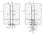
- FIG. 1shows a cross-sectional side view of an exemplary system for mine roof reinforcement according to the present invention, partially secured in a borehole in rock;
- FIG. 1Ashows a cross-sectional side view of the exemplary system of FIG. 1 with an alternate projectile
- FIG. 1Bshows a side view of another alternate projectile for use with the exemplary system of FIG. 1 ;
- FIG. 1Cshows a top view of the head portion of the projectile of FIG. 1B ;
- FIG. 2shows a cross-sectional side view of the exemplary system of FIG. 1 with a tubular member inserted in the borehole prior to expansion of the tubular member;
- FIG. 3shows a cross-sectional side view of the exemplary system of FIG. 1 with a partially expanded tubular member in the borehole;
- FIG. 4shows a cross-sectional side view of the exemplary system of FIG. 1 with an expanded tubular member in the borehole and an insertion member disposed in the tubular member;
- FIG. 5shows a cross-sectional side view of the exemplary system of FIG. 1 with an expanded tubular member in the borehole;
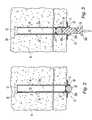
- FIG. 6shows a cross-sectional side view of a test apparatus.
- System 10for mine roof reinforcement according to the present invention, partially secured in a borehole 12 in rock 14 .
- System 10includes bearing plate 16 with an opening 16 a , tubular member 18 , and projectile 20 .
- Tubular member 18has an inner surface 22 defining an opening 22 a , outer surface 24 and a first free end 26 a .
- An enlarged portion 28is disposed proximate free end 26 .
- a clearance or gap 30Prior to travel of projectile 20 in tubular member 18 , a clearance or gap 30 preferably is disposed between tubular member 18 and rock 14 . After travel of projectile 20 , tubular member 18 is deformed such that clearance 30 is decreased.
- enlarged portion 28is integrally formed in tubular member 18 , and is circumferentially disposed about tubular member 18 .
- an increase in the inner diameter of tubular member 18is realized proximate enlarged portion 28 .
- enlarged portion 28comprises a circumferential protrusion, or a flange that may form free end 26 a .
- enlarged portion 28need not extend about the entire circumference of tubular member 18 , but may comprise one or more projections for abutting bearing plate 16 .
- Tubular member 18preferably is formed of tube having a modulus of elasticity that is greater than a bulk modulus of elasticity of rock 14 .
- tubular member 18is formed of steel (welded or seamless), however in alternate embodiments tubular member 18 is formed of other metallic materials such as aluminum or other alloys, polymer, or another deformable material.
- Tubular member 18may also include one or more layers of a deformable material on outer surface 24 such as sprayed metal and/or polymer. An elastomer coating, for example, may be applied.
- One or both of surfaces 22 , 24may include a protective coating such as paint for corrosion resistance.
- Tubular member 18may have a substantially uniform outer diameter and outer surface 24 may have a substantially circular cross-section. In alternate embodiments, at least one of inner surface 22 and outer surface 24 may have a non-circular cross-section, such as hexagonal, square, oval or otherwise oblong.
- tubular member 18is provided with one or more portions for mechanically coupling tubular member 18 to rock 14 to increase the interfacial strength between outer surface 24 and rock strata 14 .
- outer surface 24may be provided with texturing such as one or more helical, circumferential, or longitudinal grooves, a raised or depressed waffle pattern, dimples, a raised weld for example in a spiral pattern, or combinations thereof.
- the raised weldinstead may form at least one generally linear projection extending along the inner and/or outer surfaces 22 , 24 , respectively, between free ends 26 a , 26 b .
- Protrusionsmay also be formed on outer surface 24 such as small weld spatters for example in the form of raised hemispheres.
- portions of tubular member 18may be pierced or otherwise punched through, so that some of outer surface 24 extends outward for locking into rock 14 .
- Surface rougheningmay also be in the form of holes drilled into the wall of tubular member 18 .
- Various surface treatmentsmay be used to roughen outer surface 24 , such as shot peening or other deformation techniques.
- outer surface 24may be painted or otherwise coated with a roughening agent such as a polymer coating that includes glass beads, sand, or metal particles.
- a polymer reinforced with glass fiber, for example formed with polyesters,may be disposed on outer surface 24 .
- Projectile 20preferably is formed of solid, hardened steel, however in alternate embodiments projectile 20 may be hollow and may be formed of other suitable materials as described with respect to tubular member 18 .
- projectile 20is generally spherical in shape.
- a spherical projectile 20is symmetrical and thus orientation of projectile 20 is not important during assembly of system 10 .
- any shape of projectile 20 that permits suitable expansion of tubular member 18may be used.
- projectile 20has an outer diameter between about 0.75 inch and 1.5 inch; more preferably, projectile 20 has an outer diameter between about 1 inch and 1.375 inch. In alternate embodiments, as shown for example in FIG.
- a projectile 20 amay instead be provided with a generally tapered head portion 21 a (such as a conical shape) and a generally elongated body portion 21 b , which may be integrally formed.
- tapered head portion 21 a of projectile 20 amay include linear projections 21 c or splines disposed thereon for mechanically coupling projectile 20 a to tubular member 18 .
- Other shapessuch as hemispheres also may be used for projectile 20 .
- the inner diameter of tubular member 18is between 70 and 97 percent of the outer diameter of projectile 20 . More preferably, the inner diameter of tubular member 18 is between 85 and 97 percent of the outer diameter of projectile 20 , and may be between 90 and 97 percent thereof.
- FIG. 2system 10 is shown prior to anchoring in rock 14 .
- a borehole 12is formed in rock 14 , and bearing plate 16 is placed against rock 14 such that opening 16 a is aligned with borehole 12 in rock 14 .
- Tubular member 18is inserted in opening 16 a and borehole 12 , so that enlarged end 28 of tubular member 18 abuts plate 16 .
- borehole 12may extend along a first overall longitudinal length and tubular member 18 may be disposed in a portion of that length.
- a clearance of between 0 inch and 0.2 inchpreferably is formed between the tubular member and borehole prior to expansion of the tubular member, and more preferably the clearance is between 0.01 inch and 0.1 inch.
- the clearanceis selected so that tubular member 18 may be inserted in borehole 12 by hand or with a roof-bolting machine, as known in the art, and is also a function of the type of rock strata 14 .
- Projectile 20is disposed proximate enlarged end 28 for insertion into opening 22 a .
- Inner surface of tubular member 18preferably defines an inner diameter or contour that is smaller the largest outer diameter of projectile 20 .
- projectile 20 and tubular member 18are configured and dimensioned so that when projectile 20 travels along the length of tubular member 18 , at least a portion of projectile 20 has a greater width than opening 22 a , so that the width of opening 22 a may be expanded to at least frictionally engage surrounding rock 14 .
- a lubricant 31may be disposed between projectile 20 and inner surface 22 of tubular member 18 to facilitate travel of projectile 20 by reducing friction.
- Lubricant 31may be in the form of a coating on at least one of the projectile and the inner surface of the tubular member.
- a lubricantis impregnated in projectile 20 .
- projectile 20may be formed of a material that is oil-impregnated, such as oil-impregnated brass used to form bearings.
- lubricantmay be coated on a portion or all of inner surface 22 . Suitable surface coatings include Teflon® (PTFE), galvanizing, and/or grease.
- an insertion member 32may be coaxially aligned with opening 22 a in tubular member 18 , with a distal end 32 a thereof configured and dimensioned to abut projectile 20 .
- insert member 32has an outer width less than the inner width defined by inner surface 22 of tubular member 18 .
- distal end 32 ais generally flat, but in alternate embodiments distal end 32 a may be concave, convex, or otherwise shaped for engaging projectile 20 .
- Proximal end 32 b of insertion member 32may be enlarged or otherwise configured and dimensioned to receive an external force F applied by a hammer or other device.
- projectile 20is integrally formed with insertion member 32 , permitting reuse thereof in expanding multiple tubular members.
- application of force F to projectile 20causes projectile 20 to travel in opening 22 a in tubular member 18 .
- Inner surface 22 of tubular member 18defines a first inner diameter or contour that is smaller than an outer diameter or contour of projectile 20 .
- tubular member 18is mechanically expanded so that the outer surface or wall 24 thereof frictionally engages rock 14 , as seen for example in region 34 .
- Insertion member 32preferably has a length along its longitudinal axis such that distal end 32 a may travel substantially along the length of opening 22 a , thereby permitting projectile 20 to travel and finally come to rest proximate second free end 26 b of tubular member 18 , where projectile 20 may seal opening 22 a for example to provide corrosion resistance.
- insertion member 32has a length along its longitudinal axis that is selected so that when projectile 20 is disposed proximate second free end 26 b of tubular member 18 , the proximal end 32 b of insertion member 32 abuts first free end 26 a proximate enlarged portion 28 . As shown in FIG. 4 , substantially the entire opening 22 a of tubular member 18 has been mechanically expanded by the passage of projectile 20 therein.
- projectile 20may travel within opening 22 a such that projectile 20 comes to rest against an upper portion 12 a of borehole 12 in rock 14 . Insertion member 32 may then be removed therefrom.
- tubular member 18frictionally engages rock 14 with an interfacial anchorage strength preferably between 100 psi and 1000 psi, and more preferably between 200 psi and 1000 psi.
- a force that is preferably less than 20,000 poundsmay be exerted on projectile 20 to force the projectile to travel in tubular member 18 ; more preferably, this force is between 3,000 pounds and 15,000 pounds, and most preferably the force is between 4,000 pounds and 10,000 pounds.
- borehole 12is formed in rock 14 , and bearing plate 16 is placed against rock 14 so that the opening 16 a in bearing plate 16 is aligned with borehole 12 .
- Tubular member 18is inserted in borehole 12 and opening 16 a so that enlarged end 28 of tubular member 18 abuts plate 16 .
- Tubular member 18is then mechanically expanded, for example with projectile 20 , so that outer surface 24 frictionally engages rock 14 .
- borehole 12is placed in radial compression and hoop tension in the region where tubular member 18 has been expanded.
- Such radial compression and hoop tensionfrictionally retain tubular member 18 in borehole 12 because the bulk modulus of elasticity of rock 14 is lower than the modulus of elasticity of tubular member 18 .
- projectile 20expands tubular member 18 against rock strata 14 and at the same time can effect firm contact between bearing plate 6 and rock strata 14 .
- Tubular member 18is placed in axial tension and adjacent rock strata 14 in compression by a force approximately equal to the force required to effect travel of projectile 20 in tubular member 18 . Because of initial compression of rock strata 14 , some resistance to movement of rock strata 14 is conferred.
- projectile 20may be disposed proximate enlarged end 28 of tubular member 18 , and in order to force projectile 20 into tubular member 18 , the projectile 20 may be pushed by insertion member 32 . Projectile 20 may be forced through tubular member 18 to rest proximate free end 26 b opposite enlarged end 28 , and then insertion member 18 optionally may be removed from tubular member 18 . Also, after expansion of tubular member 18 , the projectile 20 optionally may be removed from tubular member 18 . In addition, at least one of projectile 20 and inner surface 22 of tubular member 18 may be lubricated. Further, enlarged end 28 may be sealed. Tubular member 18 also may be mechanically coupled to rock 14 , for example with projections such as small weld spatters disposed on outer surface 24 .
- a suitable mine roof bolting machinemay be used to apply the force needed to propel projectile 20 in tubular member 18 .
- Such machinestypically are able to exert forces of at least 10,000 lbs.
- the necessary forcemay be exerted by a percussion hammer.
- solid aluminum barswere machined to 1.260, 1.275, and 1.290 inch (32.0, 32.39, and 32.77 mm, respectively), and were centrally disposed in wet concrete section 106 . Following curing of wet concrete section 106 for 4 hours, the aluminum bars were removed and concrete section 106 was permitted to cure for a minimum elapsed time of 14 days prior to testing.
- Tube 110was disposed in borehole 108 such that a length L 5 of tube 110 of about two inches (51 mm) extended beyond each of free ends 100 a , 100 b .
- Central through hole 102 a in flange 102had a diameter of 1.375 inch, so that flange 102 would not interfere with expansion of tube 110 .
- Lower end 100 b of tube 110was swaged along a length L 6 of about 0.75 inch, and a reinforcing collar 112 was coupled thereto. Additionally, a weld 114 was placed in the inside of tube 110 to partially close lower end 110 b . The swaging and welding of lower end 110 b ensured that a projectile 116 traveling from upper end 110 a to lower end 110 b could not exit tube 110 at lower end 110 b . Performance testing was undertaken using a universal compression testing machine.
- a spacer(not shown) with a thickness of about 1.75 inch was placed under concrete section 106 and abutting flange 102 so that lower end 110 b of tube 100 abutted a bottom platen of the universal compression testing machine.
- Greasewas provided between the surface of projectile 116 and the inner surface of tube 108 to facilitate movement of projectile 116 in tube 108 .
- the greasewas a multipurpose synthetic material with molybdenum-based additives.
- An insertion memberin the form of a steel bar having an outer diameter of 1 inch was aligned so that its central longitudinal axis was generally coaxial with the central longitudinal axis of tube 110 ; one end of the steel bar abutted a top platen of the universal compression testing machine, while the other end abutted projectile 116 .
- the force F T required to push projectile 116 through the first two inches of tube 110 proximate upper, unconfined end 110 awas first measured.
- the force F C required to push projectile 116 through the section of tube 110 confined in concrete section 106was measured as projectile 116 traveled toward lower end 110 b under the force conferred by the insertion member.
- the force applied by the universal compression testing machinewas stopped.
- tube 110was roughened by providing approximately 200 small weld spatters (about 0.015 inches high and about 0.060 inches wide) thereon.
- the measured outer diameter of tube 110 after travel of projectile 116 thereinwas 1.322 inches.
- tubular member 18 proximate enlarged portion 28may be sealed with a mechanical cap, or alternatively, the wall of tubular member 18 proximate free end 26 a may include holes so that hooked objects may be hung therefrom.
- tubular member 18may be provided without an enlarged portion 28 , and an integrally formed projectile and insertion member may be inserted into tubular member 18 .
- a flared proximal end 32 b of insertion member 32may be provided to abut bearing plate 16 to retain plate 16 against rock 14 .
- the systemalso includes a projectile and an insertion member
Landscapes
- Engineering & Computer Science (AREA)
- Mining & Mineral Resources (AREA)
- Structural Engineering (AREA)
- Life Sciences & Earth Sciences (AREA)
- General Life Sciences & Earth Sciences (AREA)
- Geochemistry & Mineralogy (AREA)
- Geology (AREA)
- Excavating Of Shafts Or Tunnels (AREA)
- Earth Drilling (AREA)
- Looms (AREA)
Abstract
Description
| TABLE I | |||||||
| Test | Clearance | DB | FT | FC | FA | ||
| No. | (in.) | (in.) | (lbs.) | (lbs.) | (lbs.) | ||
| 1 | 0.005 | 1.260 | 3,000 | 6,200 | 27,000 | ||
| 2 | 0.005 | 1.260 | 3,500 | 7,500 | 22,000 | ||
| 3 | 0.020 | 1.275 | 3,500 | 6,500 | 23,000 | ||
| 4 | 0.020 | 1.275 | 3,500 | 5,500 | 18,000 | ||
| 5 | 0.035 | 1.290 | 3,200 | 4,300 | 1,500 | ||
| 6 | 0.035 | 1.290 | 3,500 | 5,200 | 21,000 | ||
As listed in Table I, forces FT, FC, and FAwere the maximum such forces experienced during each test, while the listed clearance was the clearance between the outer surface of
Claims (48)
Priority Applications (6)
| Application Number | Priority Date | Filing Date | Title |
|---|---|---|---|
| US10/292,637US6935811B2 (en) | 2002-11-13 | 2002-11-13 | Frictional mining bolt |
| CN200380106281.9ACN1726335A (en) | 2002-11-13 | 2003-11-12 | Frictional mining bolt |
| CA2505824ACA2505824C (en) | 2002-11-13 | 2003-11-12 | Frictional mining bolt |
| PCT/US2003/036236WO2004044383A1 (en) | 2002-11-13 | 2003-11-12 | Frictional mining bolt |
| AU2003287715AAU2003287715B2 (en) | 2002-11-13 | 2003-11-12 | Frictional mining bolt |
| ZA200503864AZA200503864B (en) | 2002-11-13 | 2005-05-13 | Frictional mining bolt |
Applications Claiming Priority (1)
| Application Number | Priority Date | Filing Date | Title |
|---|---|---|---|
| US10/292,637US6935811B2 (en) | 2002-11-13 | 2002-11-13 | Frictional mining bolt |
Publications (2)
| Publication Number | Publication Date |
|---|---|
| US20040091323A1 US20040091323A1 (en) | 2004-05-13 |
| US6935811B2true US6935811B2 (en) | 2005-08-30 |
Family
ID=32229494
Family Applications (1)
| Application Number | Title | Priority Date | Filing Date |
|---|---|---|---|
| US10/292,637Expired - LifetimeUS6935811B2 (en) | 2002-11-13 | 2002-11-13 | Frictional mining bolt |
Country Status (6)
| Country | Link |
|---|---|
| US (1) | US6935811B2 (en) |
| CN (1) | CN1726335A (en) |
| AU (1) | AU2003287715B2 (en) |
| CA (1) | CA2505824C (en) |
| WO (1) | WO2004044383A1 (en) |
| ZA (1) | ZA200503864B (en) |
Cited By (8)
| Publication number | Priority date | Publication date | Assignee | Title |
|---|---|---|---|---|
| US20040165958A1 (en)* | 2001-04-20 | 2004-08-26 | Mclaren Matthew David | Inserter and cap |
| US20080075539A1 (en)* | 2006-09-25 | 2008-03-27 | Vosbikian Thomas J | Friction rock stabilizer with point anchor |
| US20080219775A1 (en)* | 2007-03-09 | 2008-09-11 | Frederic Mercier-Langevin | Bolt assembly |
| WO2011153219A1 (en)* | 2010-06-04 | 2011-12-08 | Fci Holdings Delaware, Inc. | Expandable bolt with shielded tip |
| US20130156510A1 (en)* | 2011-12-14 | 2013-06-20 | Johann Steyn | Rock bolt |
| WO2014071442A1 (en)* | 2012-11-12 | 2014-05-15 | Rise Mining Developments Pty Ltd | Rock bolt |
| US20170328066A1 (en)* | 2016-05-16 | 2017-11-16 | Robert Cousineau | Marking System & Method For Use In Concrete Anchors |
| US11105356B2 (en)* | 2016-11-30 | 2021-08-31 | Andrew S. Pauba | Drop-in anchor setting tool |
Families Citing this family (6)
| Publication number | Priority date | Publication date | Assignee | Title |
|---|---|---|---|---|
| US20040161316A1 (en)* | 2003-02-19 | 2004-08-19 | F.M. Locotos Co., Inc. | Tubular mining bolt and method |
| WO2008019432A1 (en)* | 2006-08-14 | 2008-02-21 | Wmc Nominees Pty Limited | A tensioning device |
| US8807877B1 (en)* | 2008-09-19 | 2014-08-19 | Rhino Technologies Llc | Tensionable spiral bolt with resin nut and related methods |
| JP5401182B2 (en)* | 2009-06-23 | 2014-01-29 | 株式会社ケー・エフ・シー | How to install inflatable rock bolts |
| CN105569601B (en)* | 2016-02-02 | 2018-05-22 | 中国科学院武汉岩土力学研究所 | A kind of underground rock project testing bore holes orifice protecting device for adapting to different pore size |
| US20250052026A1 (en)* | 2023-07-10 | 2025-02-13 | Arrowhead Center, Inc. | Laterally expanded capacity-enhanced piles and anchors |
Citations (56)
| Publication number | Priority date | Publication date | Assignee | Title |
|---|---|---|---|---|
| US2804797A (en)* | 1954-06-23 | 1957-09-03 | Super Grip Anchor Bolt Company | Tubular, pronged reinforcing member for rock strata |
| AU747261A (en) | 1961-07-31 | 1963-05-02 | Owens-Coming Fiberglas Corporation | High temperature resistant vitreous material and method of producing same |
| CH564654A5 (en) | 1973-01-17 | 1975-07-31 | Otta Ladislav | Ground anchor for bore mounting - has deformable body for making friction contact with borehole wall |
| GB1413263A (en) | 1973-02-09 | 1975-11-12 | Scott J J | Friction rock stabilizers |
| US4126004A (en) | 1977-08-04 | 1978-11-21 | Ingersoll-Rand Company | Friction rock stabilizer |
| SU651136A1 (en) | 1976-07-15 | 1979-03-05 | Всесоюзный научно-исследовательский и проектно-конструкторский институт добычи угля гидравлическим способом | Anchor |
| DE2741092A1 (en) | 1977-09-13 | 1979-03-22 | Klaesener Presswerk Gmbh | Expanding shell mine strata-bolt - has wedges both sides of head held by ring and splayed by spring, to key into hole |
| US4195952A (en)* | 1978-03-27 | 1980-04-01 | Swanson Roger I | Means for anchoring to rock |
| US4284379A (en) | 1979-07-25 | 1981-08-18 | Ingersoll-Rand Company | Earth structure stabilizer |
| US4289426A (en) | 1979-09-14 | 1981-09-15 | Ingersoll-Rand Company | Friction rock stabilizer and method of forming same, and a method of stabilizing an earth structure |
| US4300859A (en)* | 1980-09-29 | 1981-11-17 | Waiamea Company, Inc. | Dual diameter bushing/seal for mine roof bolt |
| US4302131A (en) | 1979-06-18 | 1981-11-24 | Fosroc International Limited | Anchor elements |
| US4312604A (en) | 1980-07-17 | 1982-01-26 | Ingersoll-Rand Co. | Friction rock stabilizer set, and a method of fixing a friction rock stabilizer in an earth structure bore |
| US4382719A (en) | 1981-03-27 | 1983-05-10 | Scott James J | Methods of reinforcing and stabilizing an earth structure, and a stabilizer set therefor |
| US4459067A (en) | 1979-03-09 | 1984-07-10 | Atlas Copco Aktiebolag | Method of rock bolting and tube-formed expansion bolt |
| CA1171310A (en) | 1979-10-19 | 1984-07-24 | James C. Swain | Expanding hollow tube rock stabilizer |
| US4490074A (en) | 1982-01-12 | 1984-12-25 | Ingersoll-Rand Company | Friction rock stabilizer and sheathing means, in combination, and method of securing a friction rock stabilizer in an earth bore |
| US4502818A (en) | 1980-03-28 | 1985-03-05 | Elders G W | Roof support pin |
| US4511289A (en) | 1981-10-19 | 1985-04-16 | Atlas Copco Aktiebolag | Method of rock bolting and rock bolt |
| GB2153472A (en) | 1983-08-06 | 1985-08-21 | Edward Victor Byers | Fastening device |
| GB2153475A (en) | 1984-01-23 | 1985-08-21 | Edward Victor Byers | Anchoring of rock bolts |
| US4696606A (en)* | 1985-06-17 | 1987-09-29 | Atlas Copco Aktiebolag | Method of stabilizing a rock structure |
| USRE32645E (en) | 1982-06-25 | 1988-04-12 | Scott Investment Partners | Dynamic rock stabilizing fixture |
| US4768900A (en) | 1984-05-01 | 1988-09-06 | Burland John B | Piles and anchorages |
| WO1989006322A1 (en) | 1988-01-08 | 1989-07-13 | Kabushikikaisha Miyanaga | Expanding sleeve of anchor bolt and method of manufacturing same |
| WO1989012758A1 (en) | 1988-06-24 | 1989-12-28 | Novavit S.A. | Device comprising a pin anchored in a blind hole of at least one component |
| US4906149A (en) | 1988-05-17 | 1990-03-06 | Rockenfeller Kg | Wall plug anchor assembly for mounting in a preformed hole |
| SU1548457A1 (en) | 1987-10-28 | 1990-03-07 | В.И. Штеле | Friction-action tubular roof bolt |
| US4963062A (en)* | 1982-06-14 | 1990-10-16 | Giannuzzi Louis | Single-piece, pre-shaped anchor |
| US5017067A (en)* | 1989-05-29 | 1991-05-21 | Scantool Handelsbolag | Anchoring bolt device |
| US5033911A (en) | 1990-04-19 | 1991-07-23 | Ingersoll-Rand Company | Barrier plug for a bore |
| US5033909A (en) | 1990-04-27 | 1991-07-23 | Ingersoll-Rand Company | Coupling for anchor rod and sleeve |
| US5044851A (en) | 1988-12-23 | 1991-09-03 | Hilti Aktiengesellschaft | Fastening element assembly and method of setting fastening elements |
| US5076733A (en)* | 1990-05-04 | 1991-12-31 | Jennmar Corporation | Mine roof anchor assembly having an expansion shell assembly with a friction reducing means |
| US5112160A (en)* | 1988-07-26 | 1992-05-12 | Delkor Technik Limited | Rock anchor |
| US5114279A (en) | 1990-07-10 | 1992-05-19 | Atlas Copco Construction And Mining Technique Ab | Device for setting a rock bolt |
| US5116176A (en)* | 1990-06-20 | 1992-05-26 | Yoshino Seiki Inc. | Expansion anchor |
| US5137395A (en) | 1989-08-02 | 1992-08-11 | Ingersoll-Rand Company | Dynamic earth anchor, and a sleeve therefor |
| GB2234568B (en) | 1989-08-02 | 1993-09-15 | Ingersoll Rand Co | Earth anchor,and a sleeve therefor |
| US5314268A (en)* | 1993-01-13 | 1994-05-24 | Jennmar Corporation | Non-metallic reinforcing rod and method of use in supporting a rock formation |
| AU6870594A (en) | 1993-07-03 | 1995-02-09 | Hugotek (Proprietary) Limited | Friction rock stabilizers |
| US5582057A (en) | 1993-12-24 | 1996-12-10 | Hilti Aktiengesellschaft | Method for forming an expansion sleeve for an expansion dowel |
| US5586839A (en) | 1994-09-06 | 1996-12-24 | Gillespie; Harvey D. | Yieldable cable bolt |
| US5721047A (en)* | 1991-11-01 | 1998-02-24 | Applied Research Of Australia Pty Ltd | Polymeric moldings reinforced with tows of fibers |
| JPH10140998A (en) | 1996-11-13 | 1998-05-26 | Fujita Corp | Ground stabilization method |
| US5765969A (en) | 1994-06-02 | 1998-06-16 | Atlas Copco Rock Drill Ab | Tubeformed rock bolt |
| GB2304166B (en) | 1995-08-05 | 1999-07-28 | Hilti Ag | Straddling dowel |
| US5984562A (en)* | 1996-09-12 | 1999-11-16 | Skf Gmbh | Arrangement and method for fixing tubular element in a hole in a plate element |
| US5997219A (en) | 1996-02-21 | 1999-12-07 | Atlas Copco Rock Drill Ab | Tube-formed expansion rock bolt |
| US6048149A (en)* | 1999-02-05 | 2000-04-11 | Garcia; Enrique | Fastening anchorage assembly |
| US6048147A (en)* | 1998-04-03 | 2000-04-11 | Piolax, Inc. | Fixing clip for fixing attachment member to panel |
| NZ506394A (en) | 1999-12-01 | 2000-10-27 | Clyde Maxwell Robertson | Anchor bolt with nail driven into tube having apertures with ball shot which is expanded |
| WO2000070232A1 (en) | 1999-04-30 | 2000-11-23 | Cobra Fixations Cie. Ltee - Cobra Anchors Co. Ltd. | Sleeve bolt |
| DE10057041A1 (en) | 2000-11-17 | 2002-05-23 | Carbotech Fosroc Gmbh | Anchoring device to be used in particular for brittle areas in mining or tunneling, assembled of permanently joined mantle and folded inner tube |
| US20020076298A1 (en) | 2000-12-20 | 2002-06-20 | Societe De Prospection Et D'inventions Techniques, Spit | Anchor with an expansible sleeve for hard material |
| US20020081160A1 (en) | 1999-08-06 | 2002-06-27 | Josef Mocivnik | Expansion anchor |
- 2002
- 2002-11-13USUS10/292,637patent/US6935811B2/ennot_activeExpired - Lifetime
- 2003
- 2003-11-12CACA2505824Apatent/CA2505824C/ennot_activeExpired - Fee Related
- 2003-11-12WOPCT/US2003/036236patent/WO2004044383A1/enactiveSearch and Examination
- 2003-11-12CNCN200380106281.9Apatent/CN1726335A/enactivePending
- 2003-11-12AUAU2003287715Apatent/AU2003287715B2/ennot_activeCeased
- 2005
- 2005-05-13ZAZA200503864Apatent/ZA200503864B/enunknown
Patent Citations (61)
| Publication number | Priority date | Publication date | Assignee | Title |
|---|---|---|---|---|
| US2804797A (en)* | 1954-06-23 | 1957-09-03 | Super Grip Anchor Bolt Company | Tubular, pronged reinforcing member for rock strata |
| AU747261A (en) | 1961-07-31 | 1963-05-02 | Owens-Coming Fiberglas Corporation | High temperature resistant vitreous material and method of producing same |
| CH564654A5 (en) | 1973-01-17 | 1975-07-31 | Otta Ladislav | Ground anchor for bore mounting - has deformable body for making friction contact with borehole wall |
| GB1413263A (en) | 1973-02-09 | 1975-11-12 | Scott J J | Friction rock stabilizers |
| SU651136A1 (en) | 1976-07-15 | 1979-03-05 | Всесоюзный научно-исследовательский и проектно-конструкторский институт добычи угля гидравлическим способом | Anchor |
| US4126004A (en) | 1977-08-04 | 1978-11-21 | Ingersoll-Rand Company | Friction rock stabilizer |
| DE2741092A1 (en) | 1977-09-13 | 1979-03-22 | Klaesener Presswerk Gmbh | Expanding shell mine strata-bolt - has wedges both sides of head held by ring and splayed by spring, to key into hole |
| US4195952A (en)* | 1978-03-27 | 1980-04-01 | Swanson Roger I | Means for anchoring to rock |
| US4459067A (en) | 1979-03-09 | 1984-07-10 | Atlas Copco Aktiebolag | Method of rock bolting and tube-formed expansion bolt |
| US4302131A (en) | 1979-06-18 | 1981-11-24 | Fosroc International Limited | Anchor elements |
| US4284379A (en) | 1979-07-25 | 1981-08-18 | Ingersoll-Rand Company | Earth structure stabilizer |
| US4289426A (en) | 1979-09-14 | 1981-09-15 | Ingersoll-Rand Company | Friction rock stabilizer and method of forming same, and a method of stabilizing an earth structure |
| CA1171310A (en) | 1979-10-19 | 1984-07-24 | James C. Swain | Expanding hollow tube rock stabilizer |
| US4502818A (en) | 1980-03-28 | 1985-03-05 | Elders G W | Roof support pin |
| US4312604A (en) | 1980-07-17 | 1982-01-26 | Ingersoll-Rand Co. | Friction rock stabilizer set, and a method of fixing a friction rock stabilizer in an earth structure bore |
| US4300859A (en)* | 1980-09-29 | 1981-11-17 | Waiamea Company, Inc. | Dual diameter bushing/seal for mine roof bolt |
| US4382719A (en) | 1981-03-27 | 1983-05-10 | Scott James J | Methods of reinforcing and stabilizing an earth structure, and a stabilizer set therefor |
| US4511289A (en) | 1981-10-19 | 1985-04-16 | Atlas Copco Aktiebolag | Method of rock bolting and rock bolt |
| US4490074A (en) | 1982-01-12 | 1984-12-25 | Ingersoll-Rand Company | Friction rock stabilizer and sheathing means, in combination, and method of securing a friction rock stabilizer in an earth bore |
| US4963062A (en)* | 1982-06-14 | 1990-10-16 | Giannuzzi Louis | Single-piece, pre-shaped anchor |
| USRE32645E (en) | 1982-06-25 | 1988-04-12 | Scott Investment Partners | Dynamic rock stabilizing fixture |
| GB2153472A (en) | 1983-08-06 | 1985-08-21 | Edward Victor Byers | Fastening device |
| GB2153475A (en) | 1984-01-23 | 1985-08-21 | Edward Victor Byers | Anchoring of rock bolts |
| US4768900A (en) | 1984-05-01 | 1988-09-06 | Burland John B | Piles and anchorages |
| EP0179836B1 (en) | 1984-05-01 | 1989-01-04 | Wedge Pile And Anchorage Limited | Improvements in and relating to piles and anchorages |
| US4696606A (en)* | 1985-06-17 | 1987-09-29 | Atlas Copco Aktiebolag | Method of stabilizing a rock structure |
| SU1548457A1 (en) | 1987-10-28 | 1990-03-07 | В.И. Штеле | Friction-action tubular roof bolt |
| WO1989006322A1 (en) | 1988-01-08 | 1989-07-13 | Kabushikikaisha Miyanaga | Expanding sleeve of anchor bolt and method of manufacturing same |
| GB2224550B (en) | 1988-01-08 | 1992-05-27 | Miyanaga Kk | Anchor bolt with an expansion sleeve and a method for its manufacture |
| US4906149A (en) | 1988-05-17 | 1990-03-06 | Rockenfeller Kg | Wall plug anchor assembly for mounting in a preformed hole |
| WO1989012758A1 (en) | 1988-06-24 | 1989-12-28 | Novavit S.A. | Device comprising a pin anchored in a blind hole of at least one component |
| US5112160A (en)* | 1988-07-26 | 1992-05-12 | Delkor Technik Limited | Rock anchor |
| EP0375605B1 (en) | 1988-12-23 | 1992-02-26 | HILTI Aktiengesellschaft | Method of placing fastening members |
| US5044851A (en) | 1988-12-23 | 1991-09-03 | Hilti Aktiengesellschaft | Fastening element assembly and method of setting fastening elements |
| US5017067A (en)* | 1989-05-29 | 1991-05-21 | Scantool Handelsbolag | Anchoring bolt device |
| US5137395A (en) | 1989-08-02 | 1992-08-11 | Ingersoll-Rand Company | Dynamic earth anchor, and a sleeve therefor |
| GB2234568B (en) | 1989-08-02 | 1993-09-15 | Ingersoll Rand Co | Earth anchor,and a sleeve therefor |
| US5033911A (en) | 1990-04-19 | 1991-07-23 | Ingersoll-Rand Company | Barrier plug for a bore |
| US5033909A (en) | 1990-04-27 | 1991-07-23 | Ingersoll-Rand Company | Coupling for anchor rod and sleeve |
| US5076733A (en)* | 1990-05-04 | 1991-12-31 | Jennmar Corporation | Mine roof anchor assembly having an expansion shell assembly with a friction reducing means |
| US5116176A (en)* | 1990-06-20 | 1992-05-26 | Yoshino Seiki Inc. | Expansion anchor |
| US5114279A (en) | 1990-07-10 | 1992-05-19 | Atlas Copco Construction And Mining Technique Ab | Device for setting a rock bolt |
| US5721047A (en)* | 1991-11-01 | 1998-02-24 | Applied Research Of Australia Pty Ltd | Polymeric moldings reinforced with tows of fibers |
| US5314268A (en)* | 1993-01-13 | 1994-05-24 | Jennmar Corporation | Non-metallic reinforcing rod and method of use in supporting a rock formation |
| AU6870594A (en) | 1993-07-03 | 1995-02-09 | Hugotek (Proprietary) Limited | Friction rock stabilizers |
| US5582057A (en) | 1993-12-24 | 1996-12-10 | Hilti Aktiengesellschaft | Method for forming an expansion sleeve for an expansion dowel |
| EP0660003B1 (en) | 1993-12-24 | 1998-01-14 | HILTI Aktiengesellschaft | Method of manufacturing the expanding sleeve of an expansion dowel |
| US5765969A (en) | 1994-06-02 | 1998-06-16 | Atlas Copco Rock Drill Ab | Tubeformed rock bolt |
| US5586839A (en) | 1994-09-06 | 1996-12-24 | Gillespie; Harvey D. | Yieldable cable bolt |
| US5931619A (en) | 1995-08-05 | 1999-08-03 | Hilti Aktiengesellschaft | Expansion dowel |
| GB2304166B (en) | 1995-08-05 | 1999-07-28 | Hilti Ag | Straddling dowel |
| US5997219A (en) | 1996-02-21 | 1999-12-07 | Atlas Copco Rock Drill Ab | Tube-formed expansion rock bolt |
| US5984562A (en)* | 1996-09-12 | 1999-11-16 | Skf Gmbh | Arrangement and method for fixing tubular element in a hole in a plate element |
| JPH10140998A (en) | 1996-11-13 | 1998-05-26 | Fujita Corp | Ground stabilization method |
| US6048147A (en)* | 1998-04-03 | 2000-04-11 | Piolax, Inc. | Fixing clip for fixing attachment member to panel |
| US6048149A (en)* | 1999-02-05 | 2000-04-11 | Garcia; Enrique | Fastening anchorage assembly |
| WO2000070232A1 (en) | 1999-04-30 | 2000-11-23 | Cobra Fixations Cie. Ltee - Cobra Anchors Co. Ltd. | Sleeve bolt |
| US20020081160A1 (en) | 1999-08-06 | 2002-06-27 | Josef Mocivnik | Expansion anchor |
| NZ506394A (en) | 1999-12-01 | 2000-10-27 | Clyde Maxwell Robertson | Anchor bolt with nail driven into tube having apertures with ball shot which is expanded |
| DE10057041A1 (en) | 2000-11-17 | 2002-05-23 | Carbotech Fosroc Gmbh | Anchoring device to be used in particular for brittle areas in mining or tunneling, assembled of permanently joined mantle and folded inner tube |
| US20020076298A1 (en) | 2000-12-20 | 2002-06-20 | Societe De Prospection Et D'inventions Techniques, Spit | Anchor with an expansible sleeve for hard material |
Cited By (14)
| Publication number | Priority date | Publication date | Assignee | Title |
|---|---|---|---|---|
| US20040165958A1 (en)* | 2001-04-20 | 2004-08-26 | Mclaren Matthew David | Inserter and cap |
| US20080075539A1 (en)* | 2006-09-25 | 2008-03-27 | Vosbikian Thomas J | Friction rock stabilizer with point anchor |
| US7367751B2 (en)* | 2006-09-25 | 2008-05-06 | International Rollforms Inc. | Friction rock stabilizer with point anchor |
| WO2008039322A3 (en)* | 2006-09-25 | 2008-07-17 | Internat Rollforms Inc | Friction rock stabilizer with point anchor |
| US20080219775A1 (en)* | 2007-03-09 | 2008-09-11 | Frederic Mercier-Langevin | Bolt assembly |
| CN102939435A (en)* | 2010-06-04 | 2013-02-20 | Fci特拉华控股有限公司 | Expandable bolt with shielded tip |
| WO2011153219A1 (en)* | 2010-06-04 | 2011-12-08 | Fci Holdings Delaware, Inc. | Expandable bolt with shielded tip |
| US9062547B2 (en) | 2010-06-04 | 2015-06-23 | Fci Holdings Delaware, Inc. | Expandable bolt with shielded tip |
| CN102939435B (en)* | 2010-06-04 | 2016-02-03 | Fci特拉华控股有限公司 | With the expansion anchor rod of guard shield end |
| US20130156510A1 (en)* | 2011-12-14 | 2013-06-20 | Johann Steyn | Rock bolt |
| US8876436B2 (en)* | 2011-12-14 | 2014-11-04 | Rsc Mining (Pty) Ltd. | Rock bolt |
| WO2014071442A1 (en)* | 2012-11-12 | 2014-05-15 | Rise Mining Developments Pty Ltd | Rock bolt |
| US20170328066A1 (en)* | 2016-05-16 | 2017-11-16 | Robert Cousineau | Marking System & Method For Use In Concrete Anchors |
| US11105356B2 (en)* | 2016-11-30 | 2021-08-31 | Andrew S. Pauba | Drop-in anchor setting tool |
Also Published As
| Publication number | Publication date |
|---|---|
| AU2003287715B2 (en) | 2010-02-25 |
| ZA200503864B (en) | 2006-08-30 |
| CA2505824A1 (en) | 2004-05-27 |
| CA2505824C (en) | 2011-03-22 |
| CN1726335A (en) | 2006-01-25 |
| US20040091323A1 (en) | 2004-05-13 |
| WO2004044383A1 (en) | 2004-05-27 |
| AU2003287715A1 (en) | 2004-06-03 |
Similar Documents
| Publication | Publication Date | Title |
|---|---|---|
| US6935811B2 (en) | Frictional mining bolt | |
| EP3294991B1 (en) | Locally anchored self-drilling hollow rock bolt | |
| US5335736A (en) | Rock bolt system and method of rock bolting | |
| US4954017A (en) | Expansion bolt and mine roof reinforcement | |
| CA1171310A (en) | Expanding hollow tube rock stabilizer | |
| US5387060A (en) | Tubular mining bolt | |
| US6474701B1 (en) | Tubing connector | |
| US20040161316A1 (en) | Tubular mining bolt and method | |
| US20070269274A1 (en) | Rock Bolt | |
| US4430025A (en) | Oblate friction rock stabilizer and installation lubricating cement utilized therewith | |
| US4636115A (en) | Expansion bolt and mine roof reinforcement therewith | |
| WO2004074636A3 (en) | Radially deformed anchorage bolt | |
| US4165946A (en) | Method of securing a rock bolt | |
| AU2020213604A1 (en) | Rock bolt | |
| WO2005047652A1 (en) | Self-drilling rock bolt | |
| GB2153472A (en) | Fastening device | |
| AU739333B2 (en) | A rock bolt and method of installing a rock bolt | |
| AU755716B2 (en) | Rock bolt with keying deformations | |
| AU755393B2 (en) | Rock bolt and installing method | |
| CA2822470A1 (en) | Rock bolt | |
| JPH10169393A (en) | Friction bolt and its fixing method |
Legal Events
| Date | Code | Title | Description |
|---|---|---|---|
| AS | Assignment | Owner name:TERRASIMCO INC., WEST VIRGINIA Free format text:ASSIGNMENT OF ASSIGNORS INTEREST;ASSIGNORS:SIMMONS, WALTER NEAL;SIMMONS, WALTER JOHN;REEL/FRAME:013640/0708 Effective date:20021114 | |
| STCF | Information on status: patent grant | Free format text:PATENTED CASE | |
| CC | Certificate of correction | ||
| FEPP | Fee payment procedure | Free format text:PAT HOLDER NO LONGER CLAIMS SMALL ENTITY STATUS, ENTITY STATUS SET TO UNDISCOUNTED (ORIGINAL EVENT CODE: STOL); ENTITY STATUS OF PATENT OWNER: LARGE ENTITY | |
| REMI | Maintenance fee reminder mailed | ||
| FPAY | Fee payment | Year of fee payment:4 | |
| SULP | Surcharge for late payment | ||
| AS | Assignment | Owner name:JENNMAR OF PENNSYLVANIA, LLC,PENNSYLVANIA Free format text:MERGER;ASSIGNOR:JENNMAR CORPORATION;REEL/FRAME:024103/0575 Effective date:20091221 Owner name:FCI HOLDINGS DELAWARE, INC.,PENNSYLVANIA Free format text:PATENT ASSIGNMENT CONFIRMATION;ASSIGNOR:JENNMAR OF PENNSYLVANIA, LLC;REEL/FRAME:024103/0622 Effective date:20100317 Owner name:JENNMAR OF PENNSYLVANIA, LLC, PENNSYLVANIA Free format text:MERGER;ASSIGNOR:JENNMAR CORPORATION;REEL/FRAME:024103/0575 Effective date:20091221 Owner name:FCI HOLDINGS DELAWARE, INC., PENNSYLVANIA Free format text:PATENT ASSIGNMENT CONFIRMATION;ASSIGNOR:JENNMAR OF PENNSYLVANIA, LLC;REEL/FRAME:024103/0622 Effective date:20100317 | |
| AS | Assignment | Owner name:PNC BANK, NATIONAL ASSOCIATION, AS AGENT, PENNSYLV Free format text:SECURITY AGREEMENT;ASSIGNOR:FCI HOLDINGS DELAWARE, INC.;REEL/FRAME:026205/0001 Effective date:20110427 | |
| FPAY | Fee payment | Year of fee payment:8 | |
| AS | Assignment | Owner name:FCI HOLDINGS DELAWARE, INC., PENNSYLVANIA Free format text:RELEASE OF SECURITY INTEREST IN INTELLECTUAL PROPERTY;ASSIGNOR:PNC BANK, NATIONAL ASSOCIATION;REEL/FRAME:037963/0923 Effective date:20160229 | |
| FPAY | Fee payment | Year of fee payment:12 |