US6935098B2 - Turbomachine nozzle with noise reduction - Google Patents
Turbomachine nozzle with noise reductionDownload PDFInfo
- Publication number
- US6935098B2 US6935098B2US10/853,234US85323404AUS6935098B2US 6935098 B2US6935098 B2US 6935098B2US 85323404 AUS85323404 AUS 85323404AUS 6935098 B2US6935098 B2US 6935098B2
- Authority
- US
- United States
- Prior art keywords
- undulations
- nozzle
- series
- centerbody
- inner barrel
- Prior art date
- Legal status (The legal status is an assumption and is not a legal conclusion. Google has not performed a legal analysis and makes no representation as to the accuracy of the status listed.)
- Expired - Lifetime
Links
- 210000002105tongueAnatomy0.000claimsdescription28
- 230000000694effectsEffects0.000description9
- 239000007789gasSubstances0.000description5
- 238000000926separation methodMethods0.000description4
- 238000011144upstream manufacturingMethods0.000description4
- 239000000567combustion gasSubstances0.000description3
- 230000003071parasitic effectEffects0.000description2
- 238000005452bendingMethods0.000description1
- 230000002301combined effectEffects0.000description1
- 238000002485combustion reactionMethods0.000description1
- 230000001955cumulated effectEffects0.000description1
- 230000001186cumulative effectEffects0.000description1
- 230000000593degrading effectEffects0.000description1
- 238000005516engineering processMethods0.000description1
- 230000035939shockEffects0.000description1
Images


Classifications
- F—MECHANICAL ENGINEERING; LIGHTING; HEATING; WEAPONS; BLASTING
- F02—COMBUSTION ENGINES; HOT-GAS OR COMBUSTION-PRODUCT ENGINE PLANTS
- F02K—JET-PROPULSION PLANTS
- F02K1/00—Plants characterised by the form or arrangement of the jet pipe or nozzle; Jet pipes or nozzles peculiar thereto
- F02K1/46—Nozzles having means for adding air to the jet or for augmenting the mixing region between the jet and the ambient air, e.g. for silencing
- F02K1/48—Corrugated nozzles
Definitions
- the present inventionrelates to the general field of nozzles fitted to turbomachines. More particularly, it seeks to reduce aerodynamic noise from the jet generated at the outlet of the nozzles of airplane turbomachines that deliver separate flows, and to do so in particular while such an aircraft is taking off.
- the nozzles fitted to airplane turbomachinesgenerally comprise a centerbody surrounded by an inner barrel so as to form between them a first annular channel for a primary flow.
- An outer barrelsurrounds the inner barrel so as to form a secondary annular channel for a secondary flow.
- the primary and secondary flowsterminate, prior to being exhausted, in a converging portion, a throat, and a diverging portion.
- Overall these nozzle componentsare generally axially symmetrical in shape.
- the present inventionrelates more particularly to nozzles in which the centerbody is of the external type, i.e. having a trailing edge which is located downstream from the inner barrel.
- the present inventionseeks to reduce the jet noise generated at the outlet from such nozzles, in particular while an airplane is taking off, during which time the ejection speed of the primary and secondary flows is highly subsonic, i.e. about Mach 0.9 (high subsonic regime).
- the ejection speed of the primary and secondary flowsis highly subsonic, i.e. about Mach 0.9 (high subsonic regime).
- two conditionsmust be satisfied: firstly it is necessary to conserve constant flow sections in three dimensions both in the neck and in the diverging portion of the nozzle in order to maintain the aerodynamic performance of the nozzle and guarantee flow rate conservation, and secondly it is necessary to maintain constant cross-sections over the entire circumference of the nozzle in order to avoid local zones of excess speed.
- U.S. Pat. No. 5,924,632proposes integrating lobes on the inner and outer barrels, with the free end of the centerbody presenting various possible shapes.
- French patent No. 2 529 956describes a system for ejecting mixed flows in which the inner barrel is provided with lobes and the centerbody is provided in part with undulations. Applying those technologies to a flow at a high subsonic rate is unsatisfactory.
- the present inventionthus seeks to mitigate such drawbacks by proposing a nozzle with separate flows, the nozzle enabling the noise of the jet to be reduced, in particular in a high subsonic regime, by encouraging mixing between the flows by creating shear and turbulence effects, while nevertheless satisfying the requirements to conserve flow rate and cross-sections around the entire circumference of the nozzle.
- the inventionprovides a turbomachine nozzle comprising: a substantially cylindrical inner barrel extending along a longitudinal axis of the nozzle; a centerbody disposed concentrically inside the inner barrel and extending beyond a free end of the inner barrel in the form of a substantially conical portion so as to define between the inner barrel and the centerbody a first annular channel for receiving a primary flow having a cross-section that is substantially constant around the entire circumference of the nozzle; and an outer barrel concentrically surrounding the inner barrel so as to define a second annular channel for a secondary flow; the free end of the inner barrel presenting a surface having a first series of undulations regularly distributed around the longitudinal axis of the nozzle, the first series of undulations being formed by negative undulations which extend radially inwards relative to the inner barrel, alternating with positive undulations which extend radially outwards relative to the inner barrel.
- the centerbodypresents a second series of undulations at least in a portion facing the undulating surface at the free end of the inner barrel, the second series of undulations being regularly distributed around the longitudinal axis of the nozzle, the second series of undulations being made up of negative undulations extending radially inwards relative to the centerbody, alternating with positive undulations extending radially outwards relative to the centerbody, the negative and positive undulations of the first second series of undulations being of radial height that varies angularly and being disposed in such a manner that the negative undulations of the first series of undulations are disposed facing negative undulations of the second series of undulations, and vice versa, so as to generate turbulence and radial shear between the primary and secondary flows downstream from the undulations, while conserving a constant flow section around the entire circumference of the nozzle.
- the undulating surface of the centerbodymay extend longitudinally over its entire length or over a fraction only of the conical portion of the centerbody.
- the non-undulating surface of said conical portionmay carry a plurality of substantially rectangular arms extending longitudinally beyond a free end of the conical portion of the centerbody in their length direction and radially in their width direction, the arms intersecting on the longitudinal axis of the nozzle.
- the armsare preferably of the same length and the same width and disposed symmetrically about the longitudinal axis of the nozzle.
- the armsare disposed in line with the negative undulations of the second series of undulations. Downstream from these negative undulations, the primary flow tends to go outwards from the wall of the conical portion of the centerbody, thereby generating radial shear between the flows.
- the presence of arms in line with the negative undulationsenables this outward deflection of the flow to be increased and thus enables the radial shear effect to be increased.
- the armspresent means at a free end for generating additional radial shear between the primary and secondary flows.
- These additional shear meansmay be longitudinal slots forming an angle with the longitudinal axis of the nozzle and facing downstream therealong. The flow induced in the vicinity of these slots is thus deflected along the slots. Additional radial shear thus occurs between the flow in the vicinity of the slots (flow going away from the longitudinal axis of the nozzle) and the flow situated between the arms (flow going towards the longitudinal axis of the nozzle).
- the additional shear meansmay also be in the form of longitudinal fins that also serve to increase the shear in their vicinity and to reduce the speed of the flow along the longitudinal axis of the nozzle downstream from the arms.
- the free end of the inner barrelincludes, downstream from the first series of undulations, a series of tongues comprising negative tongues disposed in line with the negative undulations in the first series of undulations alternating with positive tongues disposed in line with the positive undulations in the first series of undulations.
- These tonguesenable the amplitude of the shear between the primary and secondary flows to be increased, in particular at medium and high frequencies.
- the tonguesinterfere simultaneously in the primary and secondary flows.
- the deflections in the flow zones generated in this way beside the primary and secondary flowsare the seat of a large amount of radial shear between the flows and strong mixing occurs between the flows between each of the flow zones defined by the tongues.
- the tonguesmay present rounded U-shaped tips or pointed V-shaped tips.
- the undulations of the second series of undulationspresent angular twist about the longitudinal axis of the nozzle so as to generate swirling in the primary flow.
- Such swirling together with the shear and the turbulence in the primary and secondary flowsfurther increases mixing at the outlet from the nozzle and thus further reduces the amount of noise that is generated.
- the undulations in the first series of undulationspreferably also present angular twisting that is equivalent to that of the undulations of the second series so as to generate swirling in the primary and secondary flows.
- Another way of generating swirling in the primary and secondary flowsis to provide the each of the negative positive undulations of the first series of undulations with at least one notch or at least one deflector fin at an angle relative to the longitudinal axis of the nozzle.
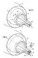
- FIG. 1is a perspective view of a turbomachine nozzle in a first embodiment of the invention
- FIGS. 2A and 2Bare respectively a cross-section view and a longitudinal section view of the FIG. 1 nozzle;
- FIG. 3is a perspective view of a turbomachine nozzle in a second embodiment of the invention.
- FIGS. 4 and 5are perspective views of the FIG. 3 nozzle showing two variants thereof;
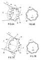
- FIGS. 6A and 6Bare respectively a perspective view and a cross-section view of the inner barrel of a nozzle constituting a third embodiment of the invention.
- FIGS. 7A and 7Bare respectively a perspective view and a cross-section view of the inner barrel of a nozzle constituting a variant of the third embodiment of the invention.
- FIG. 8is a perspective view of a nozzle in a fourth embodiment of the invention.
- FIG. 9is a perspective view of a nozzle in a fifth embodiment of the invention.
- FIG. 10is a perspective view of the inner barrel of a nozzle in a sixth embodiment of the invention.
- FIG. 11is a fragmentary perspective view of a variant of the FIG. 10 inner barrel.
- a turbomachine(not shown in the figures) comprises a fan rotated by a gas generator placed upstream from the fan.
- the gas generatorcomprises a compressor, a combustion chamber, and a turbine.
- An inner barrelis placed circularly around the gas generator and a centerbody is secured to the upstream end of the gas generator.
- the centerbodyis disposed concentrically inside the inner barrel so as to define a first annular channel for exhausting the combustion gas from the gas generator.
- the combustion gasforms the primary flow of the turbomachine.
- a pod or outer barrelis disposed concentrically around the inner barrel.
- the outer barrelis spaced radially apart from the inner barrel so as to define a second annular channel for exhausting the by pass air from the fan of the turbomachine.
- the air from the fanconstitutes the secondary flow of the turbomachine.
- the centerbody and the inner and outer barrels of the turbomachinethus form the ejection nozzle of the turbomachine.
- FIGS. 1 , 2 A, and 2 Bshow a turbomachine nozzle constituting a first embodiment of the invention.
- this nozzle 2is axially symmetrical in shape about a longitudinal axis X—X, and comprises a centerbody 4 , an inner barrel 6 , and an outer barrel 8 which are generally cylindrical in shape and are disposed concentrically relative to one another.
- references 10 and 12designate respectively the first annular channel for the primary flow and the second annular channel for the secondary flow of the turbomachine.
- the centerbody 4 of the nozzleis of the external type, i.e. its trailing edge extends longitudinally beyond a free end 14 of the inner barrel 6 . It is terminated by a substantially conical portion 16 .
- the outer barrel 8 of the nozzle shown in FIGS. 1 and 2Bdoes not extend over the full length of the inner barrel 6 . Nevertheless, the invention can also be applied to a nozzle in which the outer barrel extends over the entire length of the inner barrel, or indeed beyond it.
- the exhaust nozzle 2serves to separate the primary and secondary flows coming from the turbomachine. At the free end 14 of the inner barrel 6 , the combustion gases forming the primary flow mix with bypass air from the secondary flow.
- the axially symmetrical shape of the nozzletends to generate a high level of noise downstream from the inner barrel, particularly while an airplane is taking off.
- the present inventionprovides a special shape for the centerbody 4 and the inner barrel 6 of the nozzle for the purpose of reducing the noise generated at the nozzle outlet, while nevertheless conserving acceptable aerodynamic performance.
- the free end 14 of the inner barrel 6presents a surface 18 having a first series of undulations that are regularly distributed around the longitudinal axis X—X of the nozzle.
- This first series of undulationsis formed by negative undulations 20 , preferably eight negative undulations, that project radially inwards relative to the inner barrel 6 , and that alternate with the same number of positive undulations 22 .
- These positive undulationsextend radially outwards from the inner barrel.
- the folds formed by the first series of undulationstaper progressively in the upstream direction going away from the undulating surface 18 so as to return to the original substantially-cylindrical shape of the inner barrel 6 .
- the centerbody 4presents a second series of undulations regularly spaced apart around the longitudinal axis X—X of the nozzle, at least on a portion 24 facing the undulating surface 18 of the free end 14 of the inner barrel 6 .
- This second series of undulationsis likewise made up of negative undulations 26 that extend radially inwards relative to the centerbody 4 , alternating with positive undulations 28 that extend radially outwards relative to the centerbody.
- the folds formed in the portion 24 of the centerbody 4 of the nozzleare made in such a manner that the negative undulations 20 in the first series of undulations are located facing negative undulations 26 in the second series of undulations, and vice versa.
- the folds formed in the portion 24 of the centerbody 4taper progressively going upstream. In FIG. 1 , these same folds also taper going downstream so as to return to the original shape of the conical portion 16 of the centerbody. Nevertheless, it would also be possible for the undulating surface 24 of the centerbody 4 to extend longitudinally over the entire conical portion 16 of the centerbody.
- the folds formed in the inner barrel 6 and in the centerbody 4thus serve to generate, downstream from the undulations, radial shear between the primary and secondary flows.
- radial shearis used below to mean that the shear applies in a direction that is radial relative to the substantially-cylindrical shape of the nozzle.
- Such radial shearis shown in particular in FIG. 2B where arrows F 1 and F 2 represent the respective flow directions of the primary and secondary flows. Turbulence between the primary and secondary flows is also generated downstream from the undulating surfaces of the inner barrel and the centerbody. The undulations or folds also tend to reduce the speeds of the primary and secondary flows along the longitudinal axis X—X of the engine at the outlet from the nozzle. Thus, the combined effects of turbulence and radial shear associated with a reduction in the axial speeds of the flows leads to better mixing of the primary and secondary flows and thus leads to a reduction in the noise given off by the jet leaving the nozzle.
- the amplitude (or radial height) of the folds formed in the inner barrel 6 and the centerbody 4 of the nozzleis optimized so as to limit separation of the flows from the surfaces and avoid any risk of excess speed at the folds.
- the positive and negative undulations of the first and second series of undulationspresent a radial height (or amplitude) that varies angularly around the entire circumference of the nozzle.
- This characteristic of the inventionmakes it possible to conserve equivalent cross-sections over the entire circumference of the nozzle.
- the radial distance between the undulating surface 18 of the inner barrel 6 and the undulating surface 24 of the centerbody 4varies around the circumference of the nozzle.
- the radial distance d 1 between any of the positive undulations 22 of the inner barrel and the facing positive undulation 28 of the centerbodyis significantly different from the radial distance d 2 between any of the negative undulations 20 of the inner barrel and the corresponding negative undulation 26 of the centerbody.
- the distances d 1 and d 2are selected in such a manner that the rings traced from d 1 and d 2 present identical flow sections.
- the outline of the undulations formed in the inner barrel and the centerbody of the nozzleis such that the three-dimensional flow sections at the throat and in the divergent portion of the nozzle are conserved in comparison with a nozzle of axially symmetrical shape.
- the aerodynamic performance of the nozzleis unaffected by these undulations, with the primary and second flow rates being conserved and with any risk of local excess speed being avoided, particularly in a high subsonic regime.
- Tests performed in wind tunnelshave shown that the cumulative reduction in noise is about 3.4 decibels (dB) compared with an existing axially symmetrical nozzle having an external centerbody, and is about 5.4 dB compared with an existing axially symmetrical nozzle having an internal centerbody.
- FIG. 3shows a second embodiment of a nozzle in accordance with the invention.
- the centerbody 4 and the inner barrel 6 of the nozzlehave the same undulating surfaces 18 , 24 as the nozzle shown in FIG. 1 .
- the undulating surface 24 of the centerbody 4extends only part of the way longitudinally over the conical portion of the centerbody.
- the non-undulating surface of the conical portion of the centerbody 4i.e. the terminal portion thereof, carries a plurality of arms 30 for increasing the amplitude of the radial shear between the primary and secondary flows.
- These arms 30are substantially rectangular in shape: firstly they extend longitudinally in their long direction beyond a free end of the conical portion 16 of the centerbody 4 , and secondly they extend radially in their width direction.
- the armsintersect on the longitudinal axis X—X of the nozzle and they are advantageously all of the same length and of the same width. Furthermore, they are preferably symmetrical about the longitudinal axis X—X of the nozzle and of relatively small thickness compared with their other dimensions so as to avoid degrading the aerodynamic performance of the nozzle.
- the number of arms 30may be independent of the number of folds formed in the centerbody 4 , and their angular (or azimuth) disposition may vary, where appropriate. Nevertheless, it appears to be advantageous for the arms 30 to be positioned so that they extend the negative undulations 26 of the centerbody 4 , with the number of arms then being proportional to the number of undulations.
- the centerbody 4has eight negative undulations 26 , and at its non-undulating surface, it has eight arms 30 that are disposed symmetrically about the longitudinal axis X—X and in line with the negative undulations.
- Such an arrangementpresents the advantage of significantly increasing the radial shear generated downstream from the nozzle and thus of contributing to reducing the noise generated at the outlet from the nozzle, in particular the low frequency noise (by significantly reducing axial speed downstream from the centerbody).
- the primary and secondary flowstend to go away from the longitudinal axis X—X of the nozzle, thereby leading to radial shear between the flows.
- the arms 30 disposed in line with these negative undulationsthus contribute to accentuating this shear. It should also be observed that in the angular sectors defined between the arms, additional turbulence is created between the arms, which combine with the shear effect to contribute to reducing noise.
- longitudinal slots or notches 32are thus formed in the free ends of the arms 30 .
- These slots 32are at an angle relative to the longitudinal axis X—X of the nozzle. In order to avoid flow separation occurring in the divergent portion of the nozzle, this angle may lie, for example, in the range 0° to 5°. Furthermore, this angle is directed downstream from the nozzle, i.e. outwards from the longitudinal axis X—X of the nozzle. The flow F 3 imparted to the primary and secondary flows in the vicinity of the slots 32 is thus channeled in the slot direction.
- each of the arms 30thus presents at least four slots 32 disposed in pairs symmetrically about the longitudinal axis X—X of the nozzle.
- the means enabling additional radial shear to be generatedcan be implemented in the form of plurality fins 34 as shown in FIG. 5 .
- these fins 34are disposed perpendicularly to the arms 30 .
- the finsmay be parallel to the longitudinal axis X—X or they may be inclined relative thereto by a diverging angle of no more than 5°.
- each of the arms 30presents at least two fins 34 disposed symmetrically about the longitudinal axis X—X of the nozzle.
- the function of the fins 34is identical to the function of the above-described slots: they enable additional radial shear to be generated and they also serve to reduce the axial speed of the flows downstream from the centerbody of the nozzle under the same conditions as the slots. However, they present a wetted area that is much greater than that of the slots, thereby enabling radial shear to be increased.
- FIGS. 6A , 6 B, and 7 A, 7 Bshow part of a nozzle constituting a third embodiment of the invention.
- the centerbody and the outer barrelcontinue to present undulating surfaces in accordance with the general principle of the invention as described with reference to FIG. 1 .
- the free end 14 of the inner barrel 6 in this embodiment of the inventionpresents a surface 18 having the first series of undulations (this series of undulations is nevertheless not shown in FIGS. 6A and 7A ).
- the centerbodymay include arms optionally fitted with slots or fins as shown in FIGS. 3 to 5 .
- the free end 14 of the inner barrelincludes a series of tongues downstream from the first series of undulations, the tongues comprising negative tongues 36 , 40 disposed in line with the negative undulations in the first series of undulations alternating with positive tongues 38 , 42 disposed in line with the positive undulations in the first series of undulations.
- the negative tongues 36 , 40extend radially inwards relative to the inner barrel while the positive tongues 38 , 42 extend radially outwards relative to the inner barrel.
- the number of tonguesthus corresponds to the number of undulations in the inner barrel.
- the tonguesare of varying shapes: the free ends of the tongues may be rounded, for example, so as to form negative and positive U-shapes 36 and 38 ( FIGS. 6A , 6 B), or they may be pointed so as to form negative and positive V-shapes 40 and 42 ( FIGS. 7A , 7 B).
- the tongues as provided in this way on the trailing edge of the inner barrel 6 of the nozzleserve to increase the amplitude of the radial shear between the primary and secondary flows, and thus to accentuate the noise reduction generated at the outlet from the nozzle, particularly at medium and high frequencies (by increasing mixing between the flows outside the axial zone of the jet).
- These tonguesinterfere simultaneously with the primary and secondary flows.
- the inward and outward deflections of the flowsare consequently significantly increased compared with a surface that is merely undulating, and the wetted area is reduced compared with undulations extending as far as the tongues. This thus enables aerodynamic friction losses to be reduced.
- the primary and secondary flow deflectionsthus constitute the seat of significant radial shear between the flows, thereby increasing mixing between each of the flow zones defined by the tongues.
- angular twisting or azimuth bendingis introduced in the first and second series of undulations so as to cause the primary and secondary flows to swirl to the outlet from the nozzle.
- FIG. 8it can be seen that the positive and negative undulations of the undulating surfaces 18 and 24 of the inner barrel 6 and of the centerbody 4 are subjected to the same angular twisting about the longitudinal axis X—X of the nozzle.
- the angular twisting of the undulating surfaces 18 and 24can be implemented, for example, in the direction opposite to that of the incident flow leaving the turbine case arm of the turbomachine.
- streams F 4 and F 5 of the primary and secondary flows along the inner barrel 6 and the centerbody 4 of the nozzleare subjected to swirling in the direction opposite to the incident flow leaving the turbine case arms (not shown).
- This stream swirling effectincreases the shear effect between the primary and secondary flows and increases the phenomenon of turbulence downstream from the nozzle.
- the primary and secondary flowsremain generally directed along the longitudinal axis X—X of the nozzle.
- the undulating surfaces 18 and 24 of the inner barrel and of the centerbody of the nozzleare twisted so as to induce swirling in the primary and secondary flows.
- a consequence of such swirlingis to generate not only the radial shear induced by the undulations, but also a zone of tangential shear between the primary and secondary flows and the flow of air outside the nozzle, which flow is directed, as represented by arrow F 6 , along the longitudinal axis X—X of the nozzle.
- tangential shearis used to mean shear which acts in a direction that is tangential relative to the substantially cylindrical shape of the nozzle.
- the angular twistingis applied both to the undulating surface 18 of the inner barrel 6 and to the undulating surface 24 of the centerbody 4 .
- the angular twisting of the centerbody 4in order to maintain flow sections, it is necessary for the angular twisting of the centerbody 4 to begin at the exhaust section of the inner barrel 6 .
- the angular twistingis then generated only in the primary flow, the secondary flow being directed along the longitudinal axis of the nozzle. This embodiment thus serves to create a zone of tangential shear between the primary and secondary flows.
- the centerbody 4has two perpendicular arms 30 each disposed to extend negative undulations 26 in the centerbody. Each of these arms presents angular twisting.
- the primary flow adhering to the centerbody 4is subjected to swirling that generates additional turbulence downstream from the nozzle. Tangential shear will also occur between the swirling primary flow and the secondary flow which is directed along the longitudinal axis X—X of the nozzle.
- arms having two angular twistsa first twist in a clockwise direction followed by a second twist in the opposite direction.
- the oppositely-directed bends in the armswill then give rise in the immediately adjacent flow to swirling in both possible directions, thereby significantly increasing the turbulence effect.
- FIGS. 10 and 11show an inner barrel 6 of a nozzle in a sixth embodiment of the invention. For reasons of clarity, only the inner barrel 6 of the nozzle is shown in these figures. Naturally, the centerbody continues to present a surface that undulates in accordance with the general principle of the invention as described with reference to FIG. 1 .
- each negative and positive undulation 20 and 22 of the undulating surface 18 of the inner barrel 6 of the nozzleincludes notches 44 at an angle with the longitudinal axis X—X of the nozzle.
- These notches 44serve to direct the flow induced in the vicinity thereof outwards away from the longitudinal axis with angular deflection. The flow induced in the vicinity thereof is thus “channeled” along the notches and constitutes the seat of swirling motion that interferes with the adjacent flows.
- FIG. 11shows only part of the inner barrel, with the notches being replaced by deflector fins 46 likewise angled relative to the longitudinal axis X—X of the nozzle. As with the notches, these deflector fins 46 (two per undulation in FIG. 11 ) serve to generate a swirling effect in the flows induced in the immediate vicinity thereof. Nevertheless, deflector fins present a wetted surface area that is greater than that of notches so the swirling effect is more effective than with notches.
- the two notches 44 or deflector fins 46 per undulationare inclined relative to the longitudinal axis X—X in two opposite directions F 7 and F 8 .
- This characteristicserves to generate swirling zones in these two directions so that a suction zone is created between the two swirling zones. This suction zone encourages mixing between the flows downstream from the inner barrel.
- the present inventionthus serves to decrease significantly the noise generated at the outlet from the nozzle by encouraging mixing between the primary and secondary flows from the turbomachine. This large amount of mixing is obtained by creating radial and tangential shear between the primary and secondary flows and by acting on the turbulence and the axial speed of the flows.
Landscapes
- Engineering & Computer Science (AREA)
- Chemical & Material Sciences (AREA)
- Combustion & Propulsion (AREA)
- Mechanical Engineering (AREA)
- General Engineering & Computer Science (AREA)
- Structures Of Non-Positive Displacement Pumps (AREA)
- Nozzles (AREA)
- Tires In General (AREA)
- Turbine Rotor Nozzle Sealing (AREA)
Abstract
Description
Claims (19)
Applications Claiming Priority (2)
| Application Number | Priority Date | Filing Date | Title |
|---|---|---|---|
| FR0306484 | 2003-05-28 | ||
| FR0306484AFR2855558B1 (en) | 2003-05-28 | 2003-05-28 | TURBOMACHINE TUBE WITH NOISE REDUCTION |
Publications (2)
| Publication Number | Publication Date |
|---|---|
| US20050138915A1 US20050138915A1 (en) | 2005-06-30 |
| US6935098B2true US6935098B2 (en) | 2005-08-30 |
Family
ID=33104499
Family Applications (1)
| Application Number | Title | Priority Date | Filing Date |
|---|---|---|---|
| US10/853,234Expired - LifetimeUS6935098B2 (en) | 2003-05-28 | 2004-05-26 | Turbomachine nozzle with noise reduction |
Country Status (5)
| Country | Link |
|---|---|
| US (1) | US6935098B2 (en) |
| EP (1) | EP1482160B1 (en) |
| CA (1) | CA2469847C (en) |
| ES (1) | ES2395900T3 (en) |
| FR (1) | FR2855558B1 (en) |
Cited By (28)
| Publication number | Priority date | Publication date | Assignee | Title |
|---|---|---|---|---|
| US20050172611A1 (en)* | 2004-02-09 | 2005-08-11 | James Blodgett Keith E. | Sinuous chevron exhaust nozzle |
| US20050210860A1 (en)* | 2004-03-26 | 2005-09-29 | Gutmark Ephraim J | Methods and apparatus for operating gas turbine engines |
| US20060137323A1 (en)* | 2004-12-27 | 2006-06-29 | General Electric Company | Infrared suppressor apparatuses and method |
| US20070033922A1 (en)* | 2005-08-10 | 2007-02-15 | United Technologies Corporation | Serrated nozzle trailing edge for exhaust noise suppression |
| US20070163230A1 (en)* | 2006-01-13 | 2007-07-19 | Snecma | Core exhaust mixer, having a variable area, for turbo-fan jet engines of supersonic aircraft |
| US20080047273A1 (en)* | 2006-06-26 | 2008-02-28 | Snecma | Turbomachine nozzle cover provided with triangular patterns having pairs of vertices for reducing jet noise |
| US20080302083A1 (en)* | 2007-06-05 | 2008-12-11 | Sloan Mark L | Internal mixing of a portion of fan exhaust flow and full core exhaust flow in aircraft turbofan engines |
| US20090019857A1 (en)* | 2007-07-18 | 2009-01-22 | Rudolph Morris Tisdale | Modular chevron exhaust nozzle |
| US20090071164A1 (en)* | 2007-05-21 | 2009-03-19 | Bernard James Renggli | Fluted chevron exhaust nozzle |
| US20100032497A1 (en)* | 2007-12-21 | 2010-02-11 | Marco Rose | Nozzle with guiding elements |
| US20100139284A1 (en)* | 2008-04-15 | 2010-06-10 | Aerion Corporation | Jet nozzle plug with varying, non-circular cross sections |
| US7735601B1 (en)* | 2005-03-15 | 2010-06-15 | Rolls-Royce Plc | Engine noise |
| US7827802B2 (en)* | 2007-01-26 | 2010-11-09 | Snecma | Variable-section flow mixer for a double-flow turbojet for a supersonic airplane |
| US20110167786A1 (en)* | 2007-06-05 | 2011-07-14 | The Boeing Company | Internal mixing of a portion of fan exhaust flow and full core exhaust flow in aircraft turbofan engines |
| US20110167785A1 (en)* | 2007-06-05 | 2011-07-14 | The Boeing Company | Internal mixing of a portion of fan exhaust flow and full core exhaust flow in aircraft turbofan engines |
| US20120018543A1 (en)* | 2009-02-05 | 2012-01-26 | Snecma | Diffuser/rectifier assembly for a turbine engine |
| DE102010044483A1 (en)* | 2010-09-06 | 2012-03-08 | Mtu Aero Engines Gmbh | Bloom mixer for turbofan engine of aircraft for mixture of primary current and secondary current, has projections and recesses arranged adjacent to each other in circumferential direction and formed by walls that are formed asymmetrically |
| US20130232948A1 (en)* | 2012-03-09 | 2013-09-12 | The Boeing Company | Noise-Reducing Engine Nozzle System |
| US8635875B2 (en) | 2010-04-29 | 2014-01-28 | Pratt & Whitney Canada Corp. | Gas turbine engine exhaust mixer including circumferentially spaced-apart radial rows of tabs extending downstream on the radial walls, crests and troughs |
| US20140127010A1 (en)* | 2012-11-08 | 2014-05-08 | Rolls-Royce Deutschland Ltd & Co Kg | Nozzle with guiding devices |
| US8840451B2 (en)* | 2012-01-24 | 2014-09-23 | Honeywell International Inc. | Cabin pressure outflow valve with simplified whistle eliminator |
| US20150028129A1 (en)* | 2012-08-09 | 2015-01-29 | Snecma | Biconical exhaust cone for a civil aviation jet engine |
| US9574518B2 (en) | 2014-06-02 | 2017-02-21 | The Boeing Company | Turbofan engine with variable exhaust cooling |
| US20170082063A1 (en)* | 2012-03-09 | 2017-03-23 | The Boeing Company | Engine nozzle system for shock-cell noise reduction |
| US20170363291A1 (en)* | 2015-01-29 | 2017-12-21 | Siemens Energy, Inc. | Fuel injector including a lobed mixer and vanes for injecting alternate fuels in a gas turbine |
| US10190536B2 (en) | 2012-09-17 | 2019-01-29 | Pratt & Whitney Canada Corp. | Turbine exhaust case mixer of gas turbine with variable thickness |
| US20190323453A1 (en)* | 2018-04-24 | 2019-10-24 | The Boeing Company | Tail cone apparatus and methods for reducing nozzle surface temperatures |
| US11028778B2 (en) | 2018-09-27 | 2021-06-08 | Pratt & Whitney Canada Corp. | Engine with start assist |
Families Citing this family (22)
| Publication number | Priority date | Publication date | Assignee | Title |
|---|---|---|---|---|
| US7114323B2 (en)* | 2004-03-05 | 2006-10-03 | United Technologies Corporation | Jet exhaust noise reduction system and method |
| US7377108B2 (en)* | 2004-04-09 | 2008-05-27 | The Boeing Company | Apparatus and method for reduction jet noise from single jets |
| US20070000234A1 (en)* | 2005-06-30 | 2007-01-04 | Anderson Jack H | Jet nozzle mixer |
| US7966824B2 (en) | 2006-08-09 | 2011-06-28 | The Boeing Company | Jet engine nozzle exit configurations and associated systems and methods |
| US8157207B2 (en) | 2006-08-09 | 2012-04-17 | The Boeing Company | Jet engine nozzle exit configurations, including projections oriented relative to pylons, and associated systems and methods |
| US7870722B2 (en) | 2006-12-06 | 2011-01-18 | The Boeing Company | Systems and methods for passively directing aircraft engine nozzle flows |
| US7966826B2 (en) | 2007-02-14 | 2011-06-28 | The Boeing Company | Systems and methods for reducing noise from jet engine exhaust |
| FR2919899B1 (en)* | 2007-08-06 | 2014-02-14 | Snecma | LOBE MIXER WITH ARMS FLOW RECTIFIERS FOR TURBINE FLUID CONFLUENT FLOW TUBE |
| FR2920036B1 (en)* | 2007-08-14 | 2013-11-15 | Airbus France | ANTI-NOISE CHEVRONS FOR TUYERE |
| FR2920035B1 (en) | 2007-08-17 | 2013-09-06 | Airbus France | TURBOMOTEUR WITH REDUCED NOISE TRANSMISSION FOR AIRCRAFT |
| US8087250B2 (en) | 2008-06-26 | 2012-01-03 | General Electric Company | Duplex tab exhaust nozzle |
| CA2648765C (en)* | 2008-08-11 | 2011-04-19 | The Boeing Company | Jet engine nozzle exit configurations, including projections oriented relative to pylons, and associated systems and methods |
| FR2945838B1 (en)* | 2009-05-20 | 2014-06-13 | Snecma | TURBOMACHINE TUBE HOOD WITH SIDE FINS TO REDUCE JET NOISE. |
| IT1403221B1 (en)* | 2010-12-30 | 2013-10-17 | Nuovo Pignone Spa | PREMIXER OF Vortex COMBUSTION WITH EDWING EDGE AND METHOD |
| CN102444476B (en)* | 2011-12-15 | 2014-05-14 | 北京华清燃气轮机与煤气化联合循环工程技术有限公司 | Wave-shaped diffuser of gas turbine |
| EP2837795B1 (en)* | 2013-08-14 | 2019-05-01 | Ansaldo Energia IP UK Limited | Improved intake arrangement in gas turbine power plant |
| US9732700B2 (en) | 2013-10-24 | 2017-08-15 | The Boeing Company | Methods and apparatus for passive thrust vectoring and plume deflection |
| US9546618B2 (en)* | 2013-10-24 | 2017-01-17 | The Boeing Company | Methods and apparatus for passive thrust vectoring and plume deflection |
| FR3025255B1 (en)* | 2014-09-03 | 2016-11-04 | Turbomeca | EXHAUST TUBE OF TURBOMOTING GAS |
| PL414889A1 (en)* | 2015-11-23 | 2017-06-05 | General Electric Company | Jet engine outlet compression cowling |
| CN113074061A (en)* | 2021-04-01 | 2021-07-06 | 南昌航空大学 | Sawtooth wave crest spoiler for alternating lobe spray pipe |
| FR3159416A1 (en)* | 2024-02-19 | 2025-08-22 | Safran Aircraft Engines | Assembly for aircraft propulsion system, comprising equipment crossed by a gas flow and equipped with a flow mixer |
Citations (37)
| Publication number | Priority date | Publication date | Assignee | Title |
|---|---|---|---|---|
| FR1084419A (en) | 1952-07-25 | 1955-01-19 | Improvements in means for the at least partial suppression of noise caused by a jet of flowing fluid | |
| US3153319A (en)* | 1952-07-25 | 1964-10-20 | Young Alec David | Jet noise suppression means |
| US3192713A (en)* | 1958-03-21 | 1965-07-06 | Aerojet General Co | Combined thrust reversal and sound reduction nozzle |
| US3455413A (en)* | 1967-08-22 | 1969-07-15 | Jack C Henley | Ultrasonic silencer for jet engines |
| US3578106A (en)* | 1969-10-15 | 1971-05-11 | Rohr Corp | Turbofan propulsion silencing apparatus |
| US3592291A (en)* | 1969-11-17 | 1971-07-13 | Rohr Corp | Method and apparatus for suppressing the noise and augmenting the thrust of a jet engine |
| US3696617A (en)* | 1969-11-10 | 1972-10-10 | Rohr Corp | Turbo-fan propulsion apparatus and operating method |
| US3710890A (en)* | 1971-09-27 | 1973-01-16 | Boeing Co | Aircraft engine noise suppression |
| US3815360A (en)* | 1971-04-16 | 1974-06-11 | Rohr Industries Inc | Combined infrared and sound suppressor for aircraft jet engine |
| US3934675A (en)* | 1974-05-20 | 1976-01-27 | Lear Avia Corporation | Jet engine noise suppressor |
| US4045957A (en)* | 1976-02-20 | 1977-09-06 | United Technologies Corporation | Combined guide vane and mixer for a gas turbine engine |
| US4052847A (en)* | 1975-02-14 | 1977-10-11 | Rolls-Royce Limited | Gas turbine engine gas flow ducts |
| US4066214A (en)* | 1976-10-14 | 1978-01-03 | The Boeing Company | Gas turbine exhaust nozzle for controlled temperature flow across adjoining airfoils |
| US4077206A (en)* | 1976-04-16 | 1978-03-07 | The Boeing Company | Gas turbine mixer apparatus for suppressing engine core noise and engine fan noise |
| US4117671A (en)* | 1976-12-30 | 1978-10-03 | The Boeing Company | Noise suppressing exhaust mixer assembly for ducted-fan, turbojet engine |
| US4240252A (en)* | 1978-01-19 | 1980-12-23 | General Electric Company | Acoustically-treated mixer for a mixed flow gas turbine engine |
| US4401269A (en)* | 1980-09-26 | 1983-08-30 | United Technologies Corporation | Lobe mixer for gas turbine engine |
| FR2529956A1 (en) | 1982-07-12 | 1984-01-13 | Gen Electric | MIXED FLOW EJECTION SYSTEM |
| US4543784A (en)* | 1980-08-15 | 1985-10-01 | Rolls-Royce Limited | Exhaust flow mixers and nozzles |
| US4548034A (en)* | 1983-05-05 | 1985-10-22 | Rolls-Royce Limited | Bypass gas turbine aeroengines and exhaust mixers therefor |
| US4576002A (en)* | 1983-09-14 | 1986-03-18 | Rolls-Royce Limited | Exhaust mixer for turbofan aeroengine |
| US4592201A (en)* | 1982-07-12 | 1986-06-03 | General Electric Company | Turbofan mixed flow exhaust system |
| US4696159A (en)* | 1986-08-04 | 1987-09-29 | United Technologies Corporation | Gas turbine outlet arrangement |
| US4786016A (en)* | 1986-04-30 | 1988-11-22 | United Technologies Corporation | Bodies with reduced surface drag |
| US4819425A (en)* | 1982-03-18 | 1989-04-11 | The Boeing Company | Primary-secondary ventilated flow mixer nozzle for high bypass turbo fan jet propulsion system |
| US5216879A (en)* | 1991-08-30 | 1993-06-08 | United Technologies Corporation | Propulsion system assembly |
| US5638675A (en)* | 1995-09-08 | 1997-06-17 | United Technologies Corporation | Double lobed mixer with major and minor lobes |
| US5755092A (en)* | 1995-10-18 | 1998-05-26 | Societe Nationale D'etude Et De Construction De Moteurs D'aviation (S.N.E.C.M.A) | Exhaust nozzle mixer for a turbofan engine |
| US5924632A (en) | 1996-05-02 | 1999-07-20 | The United States Of America As Represented By The Administrator Of The National Aeronautics And Space Administration | Jet nozzle having centerbody for enhanced exit area mixing |
| US6012281A (en)* | 1997-08-18 | 2000-01-11 | United Technologies Corporation | Noise suppressing fluid mixing system for a turbine engine |
| US6082635A (en) | 1996-06-12 | 2000-07-04 | The United States Of America As Represented By The Administrator Of The National Aeronautics And Space Administration | Undulated nozzle for enhanced exit area mixing |
| WO2000040851A1 (en) | 1999-01-04 | 2000-07-13 | Allison Advanced Development Company | Exhaust mixer and apparatus using same |
| US6233920B1 (en)* | 1999-02-01 | 2001-05-22 | Stage Iii Technologies, L.C. | Contoured thrust reverser and lobed nozzle noise suppressor for gas turbine engines |
| US6276127B1 (en)* | 1999-06-22 | 2001-08-21 | John R. Alberti | Noise suppressing mixer for jet engines |
| US6786038B2 (en)* | 2002-02-22 | 2004-09-07 | The Nordam Group, Inc. | Duplex mixer exhaust nozzle |
| US6804948B2 (en)* | 2001-04-19 | 2004-10-19 | Ishikwawjima-Harima Heavy Industries, Co. Ltd. | Lobe mixer for jet engine |
| US6854260B2 (en)* | 2001-12-07 | 2005-02-15 | Jack H. Anderson | Jet nozzle mixer |
- 2003
- 2003-05-28FRFR0306484Apatent/FR2855558B1/ennot_activeExpired - Lifetime
- 2004
- 2004-05-05EPEP04291154Apatent/EP1482160B1/ennot_activeExpired - Lifetime
- 2004-05-05ESES04291154Tpatent/ES2395900T3/ennot_activeExpired - Lifetime
- 2004-05-20CACA2469847Apatent/CA2469847C/ennot_activeExpired - Lifetime
- 2004-05-26USUS10/853,234patent/US6935098B2/ennot_activeExpired - Lifetime
Patent Citations (39)
| Publication number | Priority date | Publication date | Assignee | Title |
|---|---|---|---|---|
| FR1084419A (en) | 1952-07-25 | 1955-01-19 | Improvements in means for the at least partial suppression of noise caused by a jet of flowing fluid | |
| US3153319A (en)* | 1952-07-25 | 1964-10-20 | Young Alec David | Jet noise suppression means |
| US3192713A (en)* | 1958-03-21 | 1965-07-06 | Aerojet General Co | Combined thrust reversal and sound reduction nozzle |
| US3455413A (en)* | 1967-08-22 | 1969-07-15 | Jack C Henley | Ultrasonic silencer for jet engines |
| US3578106A (en)* | 1969-10-15 | 1971-05-11 | Rohr Corp | Turbofan propulsion silencing apparatus |
| US3696617A (en)* | 1969-11-10 | 1972-10-10 | Rohr Corp | Turbo-fan propulsion apparatus and operating method |
| US3592291A (en)* | 1969-11-17 | 1971-07-13 | Rohr Corp | Method and apparatus for suppressing the noise and augmenting the thrust of a jet engine |
| US3815360A (en)* | 1971-04-16 | 1974-06-11 | Rohr Industries Inc | Combined infrared and sound suppressor for aircraft jet engine |
| US3710890A (en)* | 1971-09-27 | 1973-01-16 | Boeing Co | Aircraft engine noise suppression |
| US3934675A (en)* | 1974-05-20 | 1976-01-27 | Lear Avia Corporation | Jet engine noise suppressor |
| US4052847A (en)* | 1975-02-14 | 1977-10-11 | Rolls-Royce Limited | Gas turbine engine gas flow ducts |
| US4045957A (en)* | 1976-02-20 | 1977-09-06 | United Technologies Corporation | Combined guide vane and mixer for a gas turbine engine |
| US4077206A (en)* | 1976-04-16 | 1978-03-07 | The Boeing Company | Gas turbine mixer apparatus for suppressing engine core noise and engine fan noise |
| US4066214A (en)* | 1976-10-14 | 1978-01-03 | The Boeing Company | Gas turbine exhaust nozzle for controlled temperature flow across adjoining airfoils |
| US4117671A (en)* | 1976-12-30 | 1978-10-03 | The Boeing Company | Noise suppressing exhaust mixer assembly for ducted-fan, turbojet engine |
| US4240252A (en)* | 1978-01-19 | 1980-12-23 | General Electric Company | Acoustically-treated mixer for a mixed flow gas turbine engine |
| US4543784A (en)* | 1980-08-15 | 1985-10-01 | Rolls-Royce Limited | Exhaust flow mixers and nozzles |
| US4401269A (en)* | 1980-09-26 | 1983-08-30 | United Technologies Corporation | Lobe mixer for gas turbine engine |
| US4819425A (en)* | 1982-03-18 | 1989-04-11 | The Boeing Company | Primary-secondary ventilated flow mixer nozzle for high bypass turbo fan jet propulsion system |
| US4592201A (en)* | 1982-07-12 | 1986-06-03 | General Electric Company | Turbofan mixed flow exhaust system |
| FR2529956A1 (en) | 1982-07-12 | 1984-01-13 | Gen Electric | MIXED FLOW EJECTION SYSTEM |
| US4548034A (en)* | 1983-05-05 | 1985-10-22 | Rolls-Royce Limited | Bypass gas turbine aeroengines and exhaust mixers therefor |
| US4576002A (en)* | 1983-09-14 | 1986-03-18 | Rolls-Royce Limited | Exhaust mixer for turbofan aeroengine |
| US4786016A (en)* | 1986-04-30 | 1988-11-22 | United Technologies Corporation | Bodies with reduced surface drag |
| US4696159A (en)* | 1986-08-04 | 1987-09-29 | United Technologies Corporation | Gas turbine outlet arrangement |
| US5216879A (en)* | 1991-08-30 | 1993-06-08 | United Technologies Corporation | Propulsion system assembly |
| US5775095A (en)* | 1995-09-08 | 1998-07-07 | United Technologies Corporation | Method of noise suppression for a turbine engine |
| US5638675A (en)* | 1995-09-08 | 1997-06-17 | United Technologies Corporation | Double lobed mixer with major and minor lobes |
| US5755092A (en)* | 1995-10-18 | 1998-05-26 | Societe Nationale D'etude Et De Construction De Moteurs D'aviation (S.N.E.C.M.A) | Exhaust nozzle mixer for a turbofan engine |
| US5924632A (en) | 1996-05-02 | 1999-07-20 | The United States Of America As Represented By The Administrator Of The National Aeronautics And Space Administration | Jet nozzle having centerbody for enhanced exit area mixing |
| US6082635A (en) | 1996-06-12 | 2000-07-04 | The United States Of America As Represented By The Administrator Of The National Aeronautics And Space Administration | Undulated nozzle for enhanced exit area mixing |
| US6012281A (en)* | 1997-08-18 | 2000-01-11 | United Technologies Corporation | Noise suppressing fluid mixing system for a turbine engine |
| WO2000040851A1 (en) | 1999-01-04 | 2000-07-13 | Allison Advanced Development Company | Exhaust mixer and apparatus using same |
| US6606854B1 (en)* | 1999-01-04 | 2003-08-19 | Allison Advanced Development Company | Exhaust mixer and apparatus using same |
| US6233920B1 (en)* | 1999-02-01 | 2001-05-22 | Stage Iii Technologies, L.C. | Contoured thrust reverser and lobed nozzle noise suppressor for gas turbine engines |
| US6276127B1 (en)* | 1999-06-22 | 2001-08-21 | John R. Alberti | Noise suppressing mixer for jet engines |
| US6804948B2 (en)* | 2001-04-19 | 2004-10-19 | Ishikwawjima-Harima Heavy Industries, Co. Ltd. | Lobe mixer for jet engine |
| US6854260B2 (en)* | 2001-12-07 | 2005-02-15 | Jack H. Anderson | Jet nozzle mixer |
| US6786038B2 (en)* | 2002-02-22 | 2004-09-07 | The Nordam Group, Inc. | Duplex mixer exhaust nozzle |
Non-Patent Citations (1)
| Title |
|---|
| Search Report for FR 0306484, Feb. 16, 2004. |
Cited By (54)
| Publication number | Priority date | Publication date | Assignee | Title |
|---|---|---|---|---|
| US7305817B2 (en)* | 2004-02-09 | 2007-12-11 | General Electric Company | Sinuous chevron exhaust nozzle |
| US20050172611A1 (en)* | 2004-02-09 | 2005-08-11 | James Blodgett Keith E. | Sinuous chevron exhaust nozzle |
| US20050210860A1 (en)* | 2004-03-26 | 2005-09-29 | Gutmark Ephraim J | Methods and apparatus for operating gas turbine engines |
| US7412832B2 (en)* | 2004-03-26 | 2008-08-19 | General Electric Company | Method and apparatus for operating gas turbine engines |
| US20060137323A1 (en)* | 2004-12-27 | 2006-06-29 | General Electric Company | Infrared suppressor apparatuses and method |
| US7418813B2 (en)* | 2004-12-27 | 2008-09-02 | General Electric Company | Gas turbine engine exhaust nozzle including an infrared suppression system having a plurality of U-shaped blocking fins and method of assembling said exhaut nozzle |
| US20100170261A1 (en)* | 2005-03-15 | 2010-07-08 | Rolls-Royce Plc | Engine noise |
| US7735601B1 (en)* | 2005-03-15 | 2010-06-15 | Rolls-Royce Plc | Engine noise |
| US7543452B2 (en)* | 2005-08-10 | 2009-06-09 | United Technologies Corporation | Serrated nozzle trailing edge for exhaust noise suppression |
| US20070033922A1 (en)* | 2005-08-10 | 2007-02-15 | United Technologies Corporation | Serrated nozzle trailing edge for exhaust noise suppression |
| US20070163230A1 (en)* | 2006-01-13 | 2007-07-19 | Snecma | Core exhaust mixer, having a variable area, for turbo-fan jet engines of supersonic aircraft |
| US7810335B2 (en)* | 2006-01-13 | 2010-10-12 | Snecma | Core exhaust mixer, having a variable area, for turbo-fan jet engines of supersonic aircraft |
| US20080047273A1 (en)* | 2006-06-26 | 2008-02-28 | Snecma | Turbomachine nozzle cover provided with triangular patterns having pairs of vertices for reducing jet noise |
| US7854123B2 (en)* | 2006-06-26 | 2010-12-21 | Snecma | Turbomachine nozzle cover provided with triangular patterns having pairs of vertices for reducing jet noise |
| US7827802B2 (en)* | 2007-01-26 | 2010-11-09 | Snecma | Variable-section flow mixer for a double-flow turbojet for a supersonic airplane |
| US20090071164A1 (en)* | 2007-05-21 | 2009-03-19 | Bernard James Renggli | Fluted chevron exhaust nozzle |
| US7963099B2 (en) | 2007-05-21 | 2011-06-21 | General Electric Company | Fluted chevron exhaust nozzle |
| US20110167785A1 (en)* | 2007-06-05 | 2011-07-14 | The Boeing Company | Internal mixing of a portion of fan exhaust flow and full core exhaust flow in aircraft turbofan engines |
| US10094334B2 (en) | 2007-06-05 | 2018-10-09 | The Boeing Company | Internal mixing of a portion of fan exhaust flow and full core exhaust flow in aircraft turbofan engines |
| US10954890B2 (en) | 2007-06-05 | 2021-03-23 | The Boeing Company | Internal mixing of a portion of fan exhaust flow and full core exhaust flow in aircraft turbofan engines |
| US7762057B2 (en) | 2007-06-05 | 2010-07-27 | The Boeing Company | Internal mixing of a portion of fan exhaust flow and full core exhaust flow in aircraft turbofan engines |
| US8726665B2 (en) | 2007-06-05 | 2014-05-20 | The Boeing Company | Internal mixing of a portion of fan exhaust flow and full core exhaust flow in aircraft turbofan engines |
| US20080302083A1 (en)* | 2007-06-05 | 2008-12-11 | Sloan Mark L | Internal mixing of a portion of fan exhaust flow and full core exhaust flow in aircraft turbofan engines |
| US8341935B2 (en) | 2007-06-05 | 2013-01-01 | The Boeing Company | Internal mixing of a portion of fan exhaust flow and full core exhaust flow in aircraft turbofan engines |
| US20110167786A1 (en)* | 2007-06-05 | 2011-07-14 | The Boeing Company | Internal mixing of a portion of fan exhaust flow and full core exhaust flow in aircraft turbofan engines |
| US20090019857A1 (en)* | 2007-07-18 | 2009-01-22 | Rudolph Morris Tisdale | Modular chevron exhaust nozzle |
| US7926285B2 (en) | 2007-07-18 | 2011-04-19 | General Electric Company | Modular chevron exhaust nozzle |
| EP2072793A3 (en)* | 2007-12-21 | 2011-09-14 | Rolls-Royce Deutschland Ltd & Co KG | Nozzle with guiding elements |
| US20100032497A1 (en)* | 2007-12-21 | 2010-02-11 | Marco Rose | Nozzle with guiding elements |
| US8307659B2 (en) | 2007-12-21 | 2012-11-13 | Rolls-Royce Deutschland Ltd & Co Kg | Nozzle with guiding elements |
| US8371124B2 (en) | 2008-04-15 | 2013-02-12 | Aerion Corporation | Jet nozzle plug with varying, non-circular cross sections |
| US20100139284A1 (en)* | 2008-04-15 | 2010-06-10 | Aerion Corporation | Jet nozzle plug with varying, non-circular cross sections |
| US20120018543A1 (en)* | 2009-02-05 | 2012-01-26 | Snecma | Diffuser/rectifier assembly for a turbine engine |
| US9512733B2 (en)* | 2009-02-05 | 2016-12-06 | Snecma | Diffuser/rectifier assembly for a turbine engine with corrugated downstream walls |
| WO2010114604A1 (en)* | 2009-04-03 | 2010-10-07 | Aerion Corporation | Jet nozzle plug with varying non-circular cross sections |
| US8635875B2 (en) | 2010-04-29 | 2014-01-28 | Pratt & Whitney Canada Corp. | Gas turbine engine exhaust mixer including circumferentially spaced-apart radial rows of tabs extending downstream on the radial walls, crests and troughs |
| DE102010044483B4 (en)* | 2010-09-06 | 2016-10-27 | MTU Aero Engines AG | Flower mixer and turbomachine with such a flower mixer |
| DE102010044483A1 (en)* | 2010-09-06 | 2012-03-08 | Mtu Aero Engines Gmbh | Bloom mixer for turbofan engine of aircraft for mixture of primary current and secondary current, has projections and recesses arranged adjacent to each other in circumferential direction and formed by walls that are formed asymmetrically |
| US8840451B2 (en)* | 2012-01-24 | 2014-09-23 | Honeywell International Inc. | Cabin pressure outflow valve with simplified whistle eliminator |
| US20130232948A1 (en)* | 2012-03-09 | 2013-09-12 | The Boeing Company | Noise-Reducing Engine Nozzle System |
| US9511873B2 (en)* | 2012-03-09 | 2016-12-06 | The Boeing Company | Noise-reducing engine nozzle system |
| US20170082063A1 (en)* | 2012-03-09 | 2017-03-23 | The Boeing Company | Engine nozzle system for shock-cell noise reduction |
| US20150028129A1 (en)* | 2012-08-09 | 2015-01-29 | Snecma | Biconical exhaust cone for a civil aviation jet engine |
| US10190536B2 (en) | 2012-09-17 | 2019-01-29 | Pratt & Whitney Canada Corp. | Turbine exhaust case mixer of gas turbine with variable thickness |
| US10480452B2 (en) | 2012-09-17 | 2019-11-19 | Pratt & Whitney Canada Corp. | TEC mixer with variable thicknesses |
| US9605621B2 (en)* | 2012-11-08 | 2017-03-28 | Rolls-Royce Deutschland Ltd & Co Kg | Nozzle with guiding devices |
| US20140127010A1 (en)* | 2012-11-08 | 2014-05-08 | Rolls-Royce Deutschland Ltd & Co Kg | Nozzle with guiding devices |
| US9574518B2 (en) | 2014-06-02 | 2017-02-21 | The Boeing Company | Turbofan engine with variable exhaust cooling |
| US20170363291A1 (en)* | 2015-01-29 | 2017-12-21 | Siemens Energy, Inc. | Fuel injector including a lobed mixer and vanes for injecting alternate fuels in a gas turbine |
| US10704786B2 (en)* | 2015-01-29 | 2020-07-07 | Siemens Energy, Inc. | Fuel injector including a lobed mixer and vanes for injecting alternate fuels in a gas turbine |
| US20190323453A1 (en)* | 2018-04-24 | 2019-10-24 | The Boeing Company | Tail cone apparatus and methods for reducing nozzle surface temperatures |
| US10787994B2 (en)* | 2018-04-24 | 2020-09-29 | The Boeing Company | Tail cone apparatus and methods for reducing nozzle surface temperatures |
| US11028778B2 (en) | 2018-09-27 | 2021-06-08 | Pratt & Whitney Canada Corp. | Engine with start assist |
| US11466623B2 (en) | 2018-09-27 | 2022-10-11 | Pratt & Whitney Canada Corp. | Engine with start assist |
Also Published As
| Publication number | Publication date |
|---|---|
| US20050138915A1 (en) | 2005-06-30 |
| CA2469847A1 (en) | 2004-11-28 |
| ES2395900T3 (en) | 2013-02-15 |
| FR2855558B1 (en) | 2005-07-15 |
| CA2469847C (en) | 2011-07-12 |
| EP1482160A1 (en) | 2004-12-01 |
| EP1482160B1 (en) | 2012-10-31 |
| FR2855558A1 (en) | 2004-12-03 |
Similar Documents
| Publication | Publication Date | Title |
|---|---|---|
| US6935098B2 (en) | Turbomachine nozzle with noise reduction | |
| US6532729B2 (en) | Shelf truncated chevron exhaust nozzle for reduction of exhaust noise and infrared (IR) signature | |
| CA2851073C (en) | Exhaust mixer with offset lobes | |
| US7735601B1 (en) | Engine noise | |
| US9926942B2 (en) | Diffuser pipe with vortex generators | |
| US7966824B2 (en) | Jet engine nozzle exit configurations and associated systems and methods | |
| US8945254B2 (en) | Gas turbine engine particle separator | |
| US10385708B2 (en) | Guide assembly with optimised aerodynamic performance | |
| JP2007046598A (en) | Nozzle and gas turbine engine | |
| US20100247304A1 (en) | Exhaust plenum for a turbine engine | |
| US7310939B2 (en) | Device for reducing the jet noise of a turbomachine | |
| US11131205B2 (en) | Inter-turbine ducts with flow control mechanisms | |
| CN112502853B (en) | Nozzle, jet engine and jet aircraft equipped with the nozzle | |
| US20180202391A1 (en) | Fan exhaust for a gas turbine engine | |
| US9683516B2 (en) | Convergent-divergent nozzle for a turbine engine | |
| EP2818637B1 (en) | Gas turbine component for releasing a coolant flow into an environment subject to periodic fluctuations in pressure | |
| EP3557035B1 (en) | Turbofan engine | |
| EP3531021B1 (en) | Conduit | |
| CN110998080B (en) | Improved acoustic secondary nozzle | |
| RU2148529C1 (en) | End vortex generator for aerodynamic lifting surface | |
| US9341082B2 (en) | Pipe having an upstream core having a sharp curvature | |
| US11434773B2 (en) | Secondary flow rectifier with integrated pipe | |
| US12163486B2 (en) | Exhaust mixer with protrusions | |
| US12442532B2 (en) | Exhaust mixer with protrusions | |
| US20240230089A1 (en) | Exhaust mixer with protrusions |
Legal Events
| Date | Code | Title | Description |
|---|---|---|---|
| AS | Assignment | Owner name:SNECMA MOTEURS, FRANCE Free format text:ASSIGNMENT OF ASSIGNORS INTEREST;ASSIGNORS:BARDAGI, THIERRY;DRAVET, ALAIN;DOUSSINAULT, MARC;REEL/FRAME:015398/0720 Effective date:20040514 | |
| STCF | Information on status: patent grant | Free format text:PATENTED CASE | |
| FEPP | Fee payment procedure | Free format text:PAYOR NUMBER ASSIGNED (ORIGINAL EVENT CODE: ASPN); ENTITY STATUS OF PATENT OWNER: LARGE ENTITY | |
| FPAY | Fee payment | Year of fee payment:4 | |
| AS | Assignment | Owner name:SNECMA, FRANCE Free format text:CHANGE OF NAME;ASSIGNOR:SNECMA MOTEURS;REEL/FRAME:022473/0528 Effective date:20050512 | |
| FPAY | Fee payment | Year of fee payment:8 | |
| FPAY | Fee payment | Year of fee payment:12 | |
| AS | Assignment | Owner name:SAFRAN AIRCRAFT ENGINES, FRANCE Free format text:CHANGE OF NAME;ASSIGNOR:SNECMA;REEL/FRAME:046479/0807 Effective date:20160803 | |
| AS | Assignment | Owner name:SAFRAN AIRCRAFT ENGINES, FRANCE Free format text:CORRECTIVE ASSIGNMENT TO CORRECT THE COVER SHEET TO REMOVE APPLICATION NOS. 10250419, 10786507, 10786409, 12416418, 12531115, 12996294, 12094637 12416422 PREVIOUSLY RECORDED ON REEL 046479 FRAME 0807. ASSIGNOR(S) HEREBY CONFIRMS THE CHANGE OF NAME;ASSIGNOR:SNECMA;REEL/FRAME:046939/0336 Effective date:20160803 |