US6934676B2 - Method and system for inter-channel signal redundancy removal in perceptual audio coding - Google Patents
Method and system for inter-channel signal redundancy removal in perceptual audio codingDownload PDFInfo
- Publication number
- US6934676B2 US6934676B2US09/854,143US85414301AUS6934676B2US 6934676 B2US6934676 B2US 6934676B2US 85414301 AUS85414301 AUS 85414301AUS 6934676 B2US6934676 B2US 6934676B2
- Authority
- US
- United States
- Prior art keywords
- signals
- channel signal
- audio
- providing
- signal redundancy
- Prior art date
- Legal status (The legal status is an assumption and is not a legal conclusion. Google has not performed a legal analysis and makes no representation as to the accuracy of the status listed.)
- Expired - Lifetime
Links
- 238000000034methodMethods0.000titleclaimsabstractdescription46
- 230000005236sound signalEffects0.000claimsabstractdescription53
- 230000000873masking effectEffects0.000claimsabstractdescription20
- 230000009467reductionEffects0.000claimsdescription13
- 238000013139quantizationMethods0.000claimsdescription5
- 230000009466transformationEffects0.000claims1
- 230000005540biological transmissionEffects0.000abstractdescription7
- 239000011159matrix materialSubstances0.000description22
- 230000008569processEffects0.000description7
- 230000003595spectral effectEffects0.000description5
- 210000005069earsAnatomy0.000description3
- 230000006835compressionEffects0.000description2
- 238000007906compressionMethods0.000description2
- 230000008878couplingEffects0.000description2
- 238000010168coupling processMethods0.000description2
- 238000005859coupling reactionMethods0.000description2
- 230000007246mechanismEffects0.000description2
- 101100042407Saccharomyces cerevisiae (strain ATCC 204508 / S288c) SFB2 geneProteins0.000description1
- 238000005056compactionMethods0.000description1
- 238000010586diagramMethods0.000description1
- 230000009977dual effectEffects0.000description1
- 230000000694effectsEffects0.000description1
- 230000007774longtermEffects0.000description1
- 238000013507mappingMethods0.000description1
- 230000008520organizationEffects0.000description1
- 238000003672processing methodMethods0.000description1
- 230000002441reversible effectEffects0.000description1
Images


Classifications
- H—ELECTRICITY
- H04—ELECTRIC COMMUNICATION TECHNIQUE
- H04H—BROADCAST COMMUNICATION
- H04H20/00—Arrangements for broadcast or for distribution combined with broadcast
- H04H20/86—Arrangements characterised by the broadcast information itself
- H04H20/88—Stereophonic broadcast systems
- H04H20/89—Stereophonic broadcast systems using three or more audio channels, e.g. triphonic or quadraphonic
- G—PHYSICS
- G10—MUSICAL INSTRUMENTS; ACOUSTICS
- G10L—SPEECH ANALYSIS TECHNIQUES OR SPEECH SYNTHESIS; SPEECH RECOGNITION; SPEECH OR VOICE PROCESSING TECHNIQUES; SPEECH OR AUDIO CODING OR DECODING
- G10L19/00—Speech or audio signals analysis-synthesis techniques for redundancy reduction, e.g. in vocoders; Coding or decoding of speech or audio signals, using source filter models or psychoacoustic analysis
- G10L19/008—Multichannel audio signal coding or decoding using interchannel correlation to reduce redundancy, e.g. joint-stereo, intensity-coding or matrixing
Definitions
- the human auditory systemitself is able to detect and discard the inter-channel redundancy, thereby avoiding extra processing.
- the human auditory systemlocates sound sources mainly based on the inter-aural time difference (ITD) of the arrived signals.
- ITDinter-aural time difference
- ILDinter-aural level difference
- the psychoacoustic modelanalyzes the received signals with consecutive time blocks and determines for each block the spectral components of the received audio signal in the frequency domain in order to remove certain spectral components, thereby mimicking the masking properties of the human auditory system.
- the MPEG audio coderdoes not attempt to retain the input signal exactly after encoding and decoding, rather its goal is to reduce the amount of audio data yet maintaining the output signals similar to what the human auditory system might perceive.
- the MS Stereo coding techniqueapplies a matrix to the signals of the (L, R) or (LS, RS) pair in order to compute the sum and difference of the two original signals, dealing mainly with the spectral image at the mid-frequency range.
- Intensity Stereo codingreplaces the left and the right signals by a single representative signal plus directional information.
- the methodcan be advantageously applied to a surround sound system having a large number of sound channels (6 or more, for example).
- Such system and methodcan also be used in audio streaming over Internet Protocol (IP) for personal computer (PC) users, mobile IP and third-generation (3G) systems for mobile laptop users, digital radio, digital television, and digital archives of movie sound tracks and the like.
- IPInternet Protocol
- PCpersonal computer
- 3Gthird-generation
- the primary object of the present inventionis to improve the efficiency in encoding audio signals in a sound system in order to reduce the amount of audio data for transmission or storage.
- the methodfurther comprises the step of comparing the first value with second value for determining whether the reducing step is carried out.
- the intra-channel signal redundancy removalis carried out by a modified discrete cosine transform operation.
- the inter-channel signal redundancy reductionis carried out in an integer-to-integer discrete cosine transform operation.
- the inter-channel signal redundancy reductionis carried out in order to reduce redundancy in the audio signals in L channels, wherein L is a positive integer greater than 2 but smaller than M+1.
- the methodfurther includes the step of converting the reduced second signals into a bitstream for transmitting or storage.
- the intra-channel signal redundancy removalis carried out by a modified discrete cosine transform operation.
- the inter-channel signal redundancy reductionis carried out in an integer-to-integer discrete cosine transform operation.
- FIG. 3is a diagrammatic representation illustrating an audio coding method for inter-channel signal redundancy reduction, according to the present invention.
- FIG. 4 cis a diagrammatic representation illustrating the MDCT coefficients are divided into a plurality of scale factor bands.
- FIG. 4 dis a diagrammatic representation illustrating the audio coding method, according to the present invention, using two groups of integer-to-integer discrete cosine transform modules in an M channel sound channel system.
- the MDCT coefficients from the multiple channelsare further processed by a plurality of discrete cosine transform (DCT) devices in a cascaded manner to reduce inter-channel signal redundancy.
- the reduced signalsare quantized according to the masking threshold calculated using a psychoacoustic model and converted into a bitstream for transmission or storage, as shown in FIG. 2 . While this method can reduce the inter-channel signal redundancy, mathematically it is a challenge to relate the threshold requirements for each of the original channels in the MDCT domain to the inter-channel transformed domain (MDCT ⁇ DCT).
- a masking mechanism 50based on a so-called psychoacoustic model, is used to remove the audio data believed not be used by a human auditory system.
- the masking mechanism 50is operatively connected to the quantization unit 40 for masking out the audio data according to the intra-channel MDCT manner.
- the masked 2-D spectral imageis quantized according to the masking threshold calculated using the psychoacoustic model.
- an INT-DCT unit 60is used to perform INT-DCT inter-channel decorrelation.
- the processed MDCT coefficientsare collectively denoted by reference numeral 130 .
- L-tap INT-DCT modules 60 1 ′, . . . , 60 N ⁇ 1 ′, 60 N ′to reduce the inter-channel signal redundancy in L channels, where 2 ⁇ L ⁇ M, as shown in FIG. 4 b .
- Lleft
- Rright
- Ccenter
- LSleft-surround
- RSright-surround
- a 12-channel sound systemit is possible to perform the inter-channel decorrelation in 5 or 6 channels.
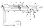
- FIG. 5shows the audio coding system 10 of present invention in more detail.
- each of M MDCT devices 30 1 , 30 2 , . . . , 30 Mare used to obtain the MDCT coefficients from a block of 2N pulsed code modulation (PCM) samples for one of the M audio channels (not shown).
- PCMpulsed code modulation
- each MDCT devicetransforms the audio signals in the time domain into the audio signals in the frequency domain.
- the audio signals in certain frequency bandsmay not produce noticeable sound in the human auditory system.
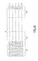
- the NMDCT coefficients for each channelare divided into a plurality of scale factor bands (SFB), modeled after the human auditory system.
- the scale factor bandwidthincreases with frequency roughly according to one third octave bandwidth.
- the N MDCT coefficients for each channelare divided into SFB 1 , SFB 2 , . . . , SFBK for further processing by N INT-DCT units.
- N128 (short window)
- K14.
- the INT-DCT unit for that SFBcan be bypassed, or the cross-channel redundancy-removal process for that SFB is not carried out.
- the comparison device 80sends a signal 124 for effecting the bypass in the encoder. It should be noted that, it is necessary for the encoder to inform the decoder whether or not INT-DCT is used for a SFB, so that the decoder knows whether an inverse INT-DCT is needed or not.
- the information sent to the decoderis known as side information.
- the side information for each SFBis only one bit, added to the bitstream 140 for transmission or storage.
- the MDCT coefficients in high frequenciesare mostly zeros.
- the P INT-DCT unitsmay be used to low and middle frequencies only.
- Any m ⁇ m orthogonal matrixcan be factorized into m(m ⁇ 1)/2 Givens rotations and m sign parameters.
- an L ⁇ L orthogonal transform matrix Ais factorized into L(L ⁇ 1)/2 Givens rotations. Givens rotations are further factorized into 3 matrices each, resulting in the total of 3L(L ⁇ 1)/2 matrix multiplications.
- 3L(L ⁇ 1)/2 multiplications and 3L(L ⁇ 1)/2 rounding operationsare needed in total for each INT-DCT operation.
Landscapes
- Engineering & Computer Science (AREA)
- Multimedia (AREA)
- Signal Processing (AREA)
- Physics & Mathematics (AREA)
- Mathematical Physics (AREA)
- Computational Linguistics (AREA)
- Health & Medical Sciences (AREA)
- Audiology, Speech & Language Pathology (AREA)
- Human Computer Interaction (AREA)
- Acoustics & Sound (AREA)
- Compression, Expansion, Code Conversion, And Decoders (AREA)
- Transmission Systems Not Characterized By The Medium Used For Transmission (AREA)
- Stereophonic System (AREA)
Abstract
Description
where ||Δ denotes rounding for the nearest integer. The inverse of (1) is
where c=cos(θ), s=sin (θ)
It follows that
G(1,2,θ3)−1·G(1,3,θ2)−1·G(2,3,θ1)−1·A=D (9)
D·G(1,2,θ3)−1·G(1,3,θ2)−1·G(2,3,θ1)−1·A=I (10)
A=G(2,3,θ1)·G(1,3,θ2)·G(1,2,θ3)·D (11)
when θ is not an integral multiple of 2π. If it is, then the Givens rotation matrix equals the unity matrix and no factorization is necessary. These factors are denoted as G(i,k,θ)1, G(i,k,θ)2and G(i,k,θ)3. A transform that behaves similarly to matrix A, maps integers to integers and is reversible is then
where x is the
Claims (17)
Priority Applications (4)
| Application Number | Priority Date | Filing Date | Title |
|---|---|---|---|
| US09/854,143US6934676B2 (en) | 2001-05-11 | 2001-05-11 | Method and system for inter-channel signal redundancy removal in perceptual audio coding |
| PCT/IB2002/001595WO2002093556A1 (en) | 2001-05-11 | 2002-05-08 | Inter-channel signal redundancy removal in perceptual audio coding |
| AT02727860TATE515018T1 (en) | 2001-05-11 | 2002-05-08 | INTERCHANNEL SIGNAL REDUNDANCY DISTANCE IN PERCEPTUAL AUDIO CODING |
| EP02727860AEP1393303B1 (en) | 2001-05-11 | 2002-05-08 | Inter-channel signal redundancy removal in perceptual audio coding |
Applications Claiming Priority (1)
| Application Number | Priority Date | Filing Date | Title |
|---|---|---|---|
| US09/854,143US6934676B2 (en) | 2001-05-11 | 2001-05-11 | Method and system for inter-channel signal redundancy removal in perceptual audio coding |
Publications (2)
| Publication Number | Publication Date |
|---|---|
| US20030014136A1 US20030014136A1 (en) | 2003-01-16 |
| US6934676B2true US6934676B2 (en) | 2005-08-23 |
Family
ID=25317845
Family Applications (1)
| Application Number | Title | Priority Date | Filing Date |
|---|---|---|---|
| US09/854,143Expired - LifetimeUS6934676B2 (en) | 2001-05-11 | 2001-05-11 | Method and system for inter-channel signal redundancy removal in perceptual audio coding |
Country Status (4)
| Country | Link |
|---|---|
| US (1) | US6934676B2 (en) |
| EP (1) | EP1393303B1 (en) |
| AT (1) | ATE515018T1 (en) |
| WO (1) | WO2002093556A1 (en) |
Cited By (20)
| Publication number | Priority date | Publication date | Assignee | Title |
|---|---|---|---|---|
| US20030236583A1 (en)* | 2002-06-24 | 2003-12-25 | Frank Baumgarte | Hybrid multi-channel/cue coding/decoding of audio signals |
| US20040102963A1 (en)* | 2002-11-21 | 2004-05-27 | Jin Li | Progressive to lossless embedded audio coder (PLEAC) with multiple factorization reversible transform |
| US20040220805A1 (en)* | 2001-06-18 | 2004-11-04 | Ralf Geiger | Method and device for processing time-discrete audio sampled values |
| US20050058304A1 (en)* | 2001-05-04 | 2005-03-17 | Frank Baumgarte | Cue-based audio coding/decoding |
| US20050180579A1 (en)* | 2004-02-12 | 2005-08-18 | Frank Baumgarte | Late reverberation-based synthesis of auditory scenes |
| US20050195981A1 (en)* | 2004-03-04 | 2005-09-08 | Christof Faller | Frequency-based coding of channels in parametric multi-channel coding systems |
| US20050252361A1 (en)* | 2002-09-06 | 2005-11-17 | Matsushita Electric Industrial Co., Ltd. | Sound encoding apparatus and sound encoding method |
| US20060085200A1 (en)* | 2004-10-20 | 2006-04-20 | Eric Allamanche | Diffuse sound shaping for BCC schemes and the like |
| US20060083385A1 (en)* | 2004-10-20 | 2006-04-20 | Eric Allamanche | Individual channel shaping for BCC schemes and the like |
| US20060115100A1 (en)* | 2004-11-30 | 2006-06-01 | Christof Faller | Parametric coding of spatial audio with cues based on transmitted channels |
| US20060153408A1 (en)* | 2005-01-10 | 2006-07-13 | Christof Faller | Compact side information for parametric coding of spatial audio |
| US20070003069A1 (en)* | 2001-05-04 | 2007-01-04 | Christof Faller | Perceptual synthesis of auditory scenes |
| US20090150161A1 (en)* | 2004-11-30 | 2009-06-11 | Agere Systems Inc. | Synchronizing parametric coding of spatial audio with externally provided downmix |
| RU2407069C2 (en)* | 2004-11-02 | 2010-12-20 | Конинклейке Филипс Электроникс Н.В. | Encoding and decoding audio signals using complex-valued filter bank |
| US20120232909A1 (en)* | 2011-03-07 | 2012-09-13 | Terriberry Timothy B | Method and system for two-step spreading for tonal artifact avoidance in audio coding |
| US8340306B2 (en) | 2004-11-30 | 2012-12-25 | Agere Systems Llc | Parametric coding of spatial audio with object-based side information |
| US9009036B2 (en) | 2011-03-07 | 2015-04-14 | Xiph.org Foundation | Methods and systems for bit allocation and partitioning in gain-shape vector quantization for audio coding |
| US9008811B2 (en) | 2010-09-17 | 2015-04-14 | Xiph.org Foundation | Methods and systems for adaptive time-frequency resolution in digital data coding |
| US9015042B2 (en) | 2011-03-07 | 2015-04-21 | Xiph.org Foundation | Methods and systems for avoiding partial collapse in multi-block audio coding |
| US11862183B2 (en) | 2020-07-06 | 2024-01-02 | Electronics And Telecommunications Research Institute | Methods of encoding and decoding audio signal using neural network model, and devices for performing the methods |
Families Citing this family (18)
| Publication number | Priority date | Publication date | Assignee | Title |
|---|---|---|---|---|
| EP1668534A4 (en)* | 2003-09-29 | 2013-08-21 | Agency Science Tech & Res | METHOD FOR TRANSFORMING A DIGITAL TIME DOMAIN SIGNAL IN THE DOMAIN FREQUENCY AND INVERSE |
| CN100517298C (en)* | 2003-09-29 | 2009-07-22 | 新加坡科技研究局 | Method for transforming digital signal from time domain to frequency domain and inverse transformation thereof |
| CN101065796A (en)* | 2004-11-24 | 2007-10-31 | 北京阜国数字技术有限公司 | Method and apparatus for encoding/decoding using inter-channel redundancy |
| WO2006075079A1 (en)* | 2005-01-14 | 2006-07-20 | France Telecom | Method for encoding audio tracks of a multimedia content to be broadcast on mobile terminals |
| JP4850827B2 (en)* | 2005-04-28 | 2012-01-11 | パナソニック株式会社 | Speech coding apparatus and speech coding method |
| EP1876586B1 (en)* | 2005-04-28 | 2010-01-06 | Panasonic Corporation | Audio encoding device and audio encoding method |
| DE102006055737A1 (en)* | 2006-11-25 | 2008-05-29 | Deutsche Telekom Ag | Method for the scalable coding of stereo signals |
| US8515767B2 (en)* | 2007-11-04 | 2013-08-20 | Qualcomm Incorporated | Technique for encoding/decoding of codebook indices for quantized MDCT spectrum in scalable speech and audio codecs |
| KR101354430B1 (en)* | 2008-07-31 | 2014-01-22 | 프라운호퍼 게젤샤프트 쭈르 푀르데룽 데어 안겐반텐 포르슝 에. 베. | Signal generation for binaural signals |
| EP2469741A1 (en)* | 2010-12-21 | 2012-06-27 | Thomson Licensing | Method and apparatus for encoding and decoding successive frames of an ambisonics representation of a 2- or 3-dimensional sound field |
| RU2464649C1 (en)* | 2011-06-01 | 2012-10-20 | Корпорация "САМСУНГ ЭЛЕКТРОНИКС Ко., Лтд." | Audio signal processing method |
| EP2743922A1 (en) | 2012-12-12 | 2014-06-18 | Thomson Licensing | Method and apparatus for compressing and decompressing a higher order ambisonics representation for a sound field |
| MX347410B (en) | 2013-01-29 | 2017-04-26 | Fraunhofer Ges Forschung | Apparatus and method for selecting one of a first audio encoding algorithm and a second audio encoding algorithm. |
| EP2830059A1 (en) | 2013-07-22 | 2015-01-28 | Fraunhofer-Gesellschaft zur Förderung der angewandten Forschung e.V. | Noise filling energy adjustment |
| WO2016142002A1 (en) | 2015-03-09 | 2016-09-15 | Fraunhofer-Gesellschaft Zur Foerderung Der Angewandten Forschung E.V. | Audio encoder, audio decoder, method for encoding an audio signal and method for decoding an encoded audio signal |
| CN109524015B (en) | 2017-09-18 | 2022-04-15 | 杭州海康威视数字技术股份有限公司 | Audio coding method, decoding method, device and audio coding and decoding system |
| EP3719799A1 (en)* | 2019-04-04 | 2020-10-07 | FRAUNHOFER-GESELLSCHAFT zur Förderung der angewandten Forschung e.V. | A multi-channel audio encoder, decoder, methods and computer program for switching between a parametric multi-channel operation and an individual channel operation |
| EP4138396A4 (en)* | 2020-05-21 | 2023-07-05 | Huawei Technologies Co., Ltd. | Audio data transmission method, and related device |
Citations (6)
| Publication number | Priority date | Publication date | Assignee | Title |
|---|---|---|---|---|
| US4375100A (en)* | 1979-10-24 | 1983-02-22 | Matsushita Electric Industrial Company, Limited | Method and apparatus for encoding low redundancy check words from source data |
| US4491869A (en) | 1981-04-03 | 1985-01-01 | Robert Bosch Gmbh | Pulse code modulation system suitable for digital recording of broadband analog signals |
| US5610908A (en)* | 1992-09-07 | 1997-03-11 | British Broadcasting Corporation | Digital signal transmission system using frequency division multiplex |
| US5638451A (en)* | 1992-07-10 | 1997-06-10 | Institut Fuer Rundfunktechnik Gmbh | Transmission and storage of multi-channel audio-signals when using bit rate-reducing coding methods |
| US5737720A (en)* | 1993-10-26 | 1998-04-07 | Sony Corporation | Low bit rate multichannel audio coding methods and apparatus using non-linear adaptive bit allocation |
| US6029129A (en)* | 1996-05-24 | 2000-02-22 | Narrative Communications Corporation | Quantizing audio data using amplitude histogram |
Family Cites Families (5)
| Publication number | Priority date | Publication date | Assignee | Title |
|---|---|---|---|---|
| US5488665A (en)* | 1993-11-23 | 1996-01-30 | At&T Corp. | Multi-channel perceptual audio compression system with encoding mode switching among matrixed channels |
| JP3404837B2 (en)* | 1993-12-07 | 2003-05-12 | ソニー株式会社 | Multi-layer coding device |
| KR970005131B1 (en)* | 1994-01-18 | 1997-04-12 | 대우전자 주식회사 | Digital Audio Coding Device Adaptive to Human Auditory Characteristics |
| EP0688113A2 (en)* | 1994-06-13 | 1995-12-20 | Sony Corporation | Method and apparatus for encoding and decoding digital audio signals and apparatus for recording digital audio |
| US5812971A (en)* | 1996-03-22 | 1998-09-22 | Lucent Technologies Inc. | Enhanced joint stereo coding method using temporal envelope shaping |
- 2001
- 2001-05-11USUS09/854,143patent/US6934676B2/ennot_activeExpired - Lifetime
- 2002
- 2002-05-08ATAT02727860Tpatent/ATE515018T1/ennot_activeIP Right Cessation
- 2002-05-08EPEP02727860Apatent/EP1393303B1/ennot_activeExpired - Lifetime
- 2002-05-08WOPCT/IB2002/001595patent/WO2002093556A1/ennot_activeApplication Discontinuation
Patent Citations (6)
| Publication number | Priority date | Publication date | Assignee | Title |
|---|---|---|---|---|
| US4375100A (en)* | 1979-10-24 | 1983-02-22 | Matsushita Electric Industrial Company, Limited | Method and apparatus for encoding low redundancy check words from source data |
| US4491869A (en) | 1981-04-03 | 1985-01-01 | Robert Bosch Gmbh | Pulse code modulation system suitable for digital recording of broadband analog signals |
| US5638451A (en)* | 1992-07-10 | 1997-06-10 | Institut Fuer Rundfunktechnik Gmbh | Transmission and storage of multi-channel audio-signals when using bit rate-reducing coding methods |
| US5610908A (en)* | 1992-09-07 | 1997-03-11 | British Broadcasting Corporation | Digital signal transmission system using frequency division multiplex |
| US5737720A (en)* | 1993-10-26 | 1998-04-07 | Sony Corporation | Low bit rate multichannel audio coding methods and apparatus using non-linear adaptive bit allocation |
| US6029129A (en)* | 1996-05-24 | 2000-02-22 | Narrative Communications Corporation | Quantizing audio data using amplitude histogram |
Non-Patent Citations (4)
| Title |
|---|
| "An Inter-Channel Redundancy Removal Approach for High-Quality Multichannel Audio Compression"; D. Yang, H. Ai, C. Kyriakakis, C. J. Kuo; Presented at 109<SUP>th </SUP>AES Convention, Sep. 22-25, 2000, Los Angeles, CA. |
| "Transform Coding with Integer-to-Integer Transforms", V. K. Goyal, IEEE Tranasactions on Information Theory, vol. 46, No. 2, Mar. 2000, pp. 465-473. |
| Chen et al, "Video Compression Using Integer DCT", Image Processing, 2000, Proceedings 2000 International Conference, vol. 2, pp. 844-845.* |
| Cheng et al, "Integer discrete cosine transform and its fast algorithm," Electronic Letters, vol. 37, Jan. 4, 2001, pp. 64-65.* |
Cited By (40)
| Publication number | Priority date | Publication date | Assignee | Title |
|---|---|---|---|---|
| US8200500B2 (en) | 2001-05-04 | 2012-06-12 | Agere Systems Inc. | Cue-based audio coding/decoding |
| US20070003069A1 (en)* | 2001-05-04 | 2007-01-04 | Christof Faller | Perceptual synthesis of auditory scenes |
| US20110164756A1 (en)* | 2001-05-04 | 2011-07-07 | Agere Systems Inc. | Cue-Based Audio Coding/Decoding |
| US20050058304A1 (en)* | 2001-05-04 | 2005-03-17 | Frank Baumgarte | Cue-based audio coding/decoding |
| US7941320B2 (en) | 2001-05-04 | 2011-05-10 | Agere Systems, Inc. | Cue-based audio coding/decoding |
| US7693721B2 (en) | 2001-05-04 | 2010-04-06 | Agere Systems Inc. | Hybrid multi-channel/cue coding/decoding of audio signals |
| US20090319281A1 (en)* | 2001-05-04 | 2009-12-24 | Agere Systems Inc. | Cue-based audio coding/decoding |
| US7644003B2 (en) | 2001-05-04 | 2010-01-05 | Agere Systems Inc. | Cue-based audio coding/decoding |
| US7512539B2 (en)* | 2001-06-18 | 2009-03-31 | Fraunhofer-Gesellschaft Zur Foerderung Der Angewandten Forschung E.V. | Method and device for processing time-discrete audio sampled values |
| US20040220805A1 (en)* | 2001-06-18 | 2004-11-04 | Ralf Geiger | Method and device for processing time-discrete audio sampled values |
| US20030236583A1 (en)* | 2002-06-24 | 2003-12-25 | Frank Baumgarte | Hybrid multi-channel/cue coding/decoding of audio signals |
| US7292901B2 (en)* | 2002-06-24 | 2007-11-06 | Agere Systems Inc. | Hybrid multi-channel/cue coding/decoding of audio signals |
| US20050252361A1 (en)* | 2002-09-06 | 2005-11-17 | Matsushita Electric Industrial Co., Ltd. | Sound encoding apparatus and sound encoding method |
| US7996233B2 (en)* | 2002-09-06 | 2011-08-09 | Panasonic Corporation | Acoustic coding of an enhancement frame having a shorter time length than a base frame |
| US7395210B2 (en)* | 2002-11-21 | 2008-07-01 | Microsoft Corporation | Progressive to lossless embedded audio coder (PLEAC) with multiple factorization reversible transform |
| US20040102963A1 (en)* | 2002-11-21 | 2004-05-27 | Jin Li | Progressive to lossless embedded audio coder (PLEAC) with multiple factorization reversible transform |
| US7583805B2 (en) | 2004-02-12 | 2009-09-01 | Agere Systems Inc. | Late reverberation-based synthesis of auditory scenes |
| US20050180579A1 (en)* | 2004-02-12 | 2005-08-18 | Frank Baumgarte | Late reverberation-based synthesis of auditory scenes |
| US7805313B2 (en) | 2004-03-04 | 2010-09-28 | Agere Systems Inc. | Frequency-based coding of channels in parametric multi-channel coding systems |
| US20050195981A1 (en)* | 2004-03-04 | 2005-09-08 | Christof Faller | Frequency-based coding of channels in parametric multi-channel coding systems |
| US8238562B2 (en) | 2004-10-20 | 2012-08-07 | Fraunhofer-Gesellschaft Zur Foerderung Der Angewandten Forschung E.V. | Diffuse sound shaping for BCC schemes and the like |
| US20060083385A1 (en)* | 2004-10-20 | 2006-04-20 | Eric Allamanche | Individual channel shaping for BCC schemes and the like |
| US8204261B2 (en) | 2004-10-20 | 2012-06-19 | Fraunhofer-Gesellschaft Zur Foerderung Der Angewandten Forschung E.V. | Diffuse sound shaping for BCC schemes and the like |
| US7720230B2 (en) | 2004-10-20 | 2010-05-18 | Agere Systems, Inc. | Individual channel shaping for BCC schemes and the like |
| US20060085200A1 (en)* | 2004-10-20 | 2006-04-20 | Eric Allamanche | Diffuse sound shaping for BCC schemes and the like |
| US20090319282A1 (en)* | 2004-10-20 | 2009-12-24 | Agere Systems Inc. | Diffuse sound shaping for bcc schemes and the like |
| RU2407069C2 (en)* | 2004-11-02 | 2010-12-20 | Конинклейке Филипс Электроникс Н.В. | Encoding and decoding audio signals using complex-valued filter bank |
| US20060115100A1 (en)* | 2004-11-30 | 2006-06-01 | Christof Faller | Parametric coding of spatial audio with cues based on transmitted channels |
| US20090150161A1 (en)* | 2004-11-30 | 2009-06-11 | Agere Systems Inc. | Synchronizing parametric coding of spatial audio with externally provided downmix |
| US7787631B2 (en) | 2004-11-30 | 2010-08-31 | Agere Systems Inc. | Parametric coding of spatial audio with cues based on transmitted channels |
| US7761304B2 (en) | 2004-11-30 | 2010-07-20 | Agere Systems Inc. | Synchronizing parametric coding of spatial audio with externally provided downmix |
| US8340306B2 (en) | 2004-11-30 | 2012-12-25 | Agere Systems Llc | Parametric coding of spatial audio with object-based side information |
| US20060153408A1 (en)* | 2005-01-10 | 2006-07-13 | Christof Faller | Compact side information for parametric coding of spatial audio |
| US7903824B2 (en) | 2005-01-10 | 2011-03-08 | Agere Systems Inc. | Compact side information for parametric coding of spatial audio |
| US9008811B2 (en) | 2010-09-17 | 2015-04-14 | Xiph.org Foundation | Methods and systems for adaptive time-frequency resolution in digital data coding |
| US20120232909A1 (en)* | 2011-03-07 | 2012-09-13 | Terriberry Timothy B | Method and system for two-step spreading for tonal artifact avoidance in audio coding |
| US8838442B2 (en)* | 2011-03-07 | 2014-09-16 | Xiph.org Foundation | Method and system for two-step spreading for tonal artifact avoidance in audio coding |
| US9009036B2 (en) | 2011-03-07 | 2015-04-14 | Xiph.org Foundation | Methods and systems for bit allocation and partitioning in gain-shape vector quantization for audio coding |
| US9015042B2 (en) | 2011-03-07 | 2015-04-21 | Xiph.org Foundation | Methods and systems for avoiding partial collapse in multi-block audio coding |
| US11862183B2 (en) | 2020-07-06 | 2024-01-02 | Electronics And Telecommunications Research Institute | Methods of encoding and decoding audio signal using neural network model, and devices for performing the methods |
Also Published As
| Publication number | Publication date |
|---|---|
| EP1393303A1 (en) | 2004-03-03 |
| EP1393303A4 (en) | 2009-08-05 |
| ATE515018T1 (en) | 2011-07-15 |
| US20030014136A1 (en) | 2003-01-16 |
| WO2002093556A1 (en) | 2002-11-21 |
| EP1393303B1 (en) | 2011-06-29 |
Similar Documents
| Publication | Publication Date | Title |
|---|---|---|
| US6934676B2 (en) | Method and system for inter-channel signal redundancy removal in perceptual audio coding | |
| US11798568B2 (en) | Methods, apparatus and systems for encoding and decoding of multi-channel ambisonics audio data | |
| CN100442850C (en) | Method and system for lossless data encoding and decoding | |
| CN112735447B (en) | Method and apparatus for compressing and decompressing a higher order ambisonics signal representation | |
| Davis | The AC-3 multichannel coder | |
| US20110085669A1 (en) | Method for Encoding and Decoding Multi-Channel Audio Signal and Apparatus Thereof | |
| EP1175030B1 (en) | Method and system for multichannel perceptual audio coding using the cascaded discrete cosine transform or modified discrete cosine transform | |
| US20170164131A1 (en) | Method and apparatus for decoding a compressed hoa representation, and method and apparatus for encoding a compressed hoa representation | |
| JP2009510514A (en) | Multi-channel audio signal encoding / decoding method and apparatus | |
| US9794714B2 (en) | Method and apparatus for decoding a compressed HOA representation, and method and apparatus for encoding a compressed HOA representation | |
| JP4685165B2 (en) | Interchannel level difference quantization and inverse quantization method based on virtual sound source position information | |
| US20110137661A1 (en) | Quantizing device, encoding device, quantizing method, and encoding method | |
| EP2688065A1 (en) | Method and apparatus for avoiding unmasking of coding noise when mixing perceptually coded multi-channel audio signals | |
| JPH09252254A (en) | Audio decoder | |
| Goodwin et al. | Analysis and synthesis for universal spatial audio coding | |
| EP1779385B1 (en) | Method and apparatus for encoding and decoding multi-channel audio signal using virtual source location information | |
| KR20040044389A (en) | Coding method, apparatus, decoding method, and apparatus | |
| JPH09130260A (en) | Encoding device and decoding device for acoustic signal | |
| JPH08123488A (en) | High-efficiency encoding method, high-efficiency code recording method, high-efficiency code transmitting method, high-efficiency encoding device, and high-efficiency code decoding method | |
| JPH09135173A (en) | Device and method for encoding, device and method for decoding, device and method for transmission and recording medium | |
| HK40051314B (en) | Method and apparatus for compressing and decompressing a higher order ambisonics signal representation | |
| HK40051314A (en) | Method and apparatus for compressing and decompressing a higher order ambisonics signal representation | |
| HK40050574B (en) | Method and apparatus for compressing and decompressing a higher order ambisonics signal representation | |
| HK1238787A1 (en) | Method and apparatus for compressing and decompressing a higher order ambisonics signal representation | |
| HK1238786A1 (en) | Method and apparatus for compressing and decompressing a higher order ambisonics signal representation |
Legal Events
| Date | Code | Title | Description |
|---|---|---|---|
| AS | Assignment | Owner name:NOKIA MOBILE PHONES LTD., FINLAND Free format text:ASSIGNMENT OF ASSIGNORS INTEREST;ASSIGNORS:WANG, YE;VILERMO, MIIKKA;REEL/FRAME:012009/0011 Effective date:20010608 | |
| STCF | Information on status: patent grant | Free format text:PATENTED CASE | |
| CC | Certificate of correction | ||
| FPAY | Fee payment | Year of fee payment:4 | |
| AS | Assignment | Owner name:NOKIA CORPORATION, FINLAND Free format text:MERGER;ASSIGNOR:NOKIA MOBILE PHONES LTD.;REEL/FRAME:026101/0560 Effective date:20080612 | |
| AS | Assignment | Owner name:NOKIA CORPORATION, FINLAND Free format text:SHORT FORM PATENT SECURITY AGREEMENT;ASSIGNOR:CORE WIRELESS LICENSING S.A.R.L.;REEL/FRAME:026894/0665 Effective date:20110901 Owner name:MICROSOFT CORPORATION, WASHINGTON Free format text:SHORT FORM PATENT SECURITY AGREEMENT;ASSIGNOR:CORE WIRELESS LICENSING S.A.R.L.;REEL/FRAME:026894/0665 Effective date:20110901 | |
| AS | Assignment | Owner name:NOKIA 2011 PATENT TRUST, DELAWARE Free format text:ASSIGNMENT OF ASSIGNORS INTEREST;ASSIGNOR:NOKIA CORPORATION;REEL/FRAME:027120/0608 Effective date:20110531 Owner name:2011 INTELLECTUAL PROPERTY ASSET TRUST, DELAWARE Free format text:CHANGE OF NAME;ASSIGNOR:NOKIA 2011 PATENT TRUST;REEL/FRAME:027121/0353 Effective date:20110901 | |
| AS | Assignment | Owner name:CORE WIRELESS LICENSING S.A.R.L, LUXEMBOURG Free format text:ASSIGNMENT OF ASSIGNORS INTEREST;ASSIGNOR:2011 INTELLECTUAL PROPERTY ASSET TRUST;REEL/FRAME:027484/0797 Effective date:20110831 | |
| FPAY | Fee payment | Year of fee payment:8 | |
| AS | Assignment | Owner name:MICROSOFT CORPORATION, WASHINGTON Free format text:UCC FINANCING STATEMENT AMENDMENT - DELETION OF SECURED PARTY;ASSIGNOR:NOKIA CORPORATION;REEL/FRAME:039872/0112 Effective date:20150327 | |
| AS | Assignment | Owner name:CORE WIRELESS LICENSING S.A.R.L., LUXEMBOURG Free format text:SECURITY INTEREST;ASSIGNOR:NOKIA CORPORATION;REEL/FRAME:039873/0650 Effective date:20160923 Owner name:CORE WIRELESS LICENSING S.A.R.L., LUXEMBOURG Free format text:RELEASE BY SECURED PARTY;ASSIGNOR:NOKIA CORPORATION;REEL/FRAME:039873/0877 Effective date:20160923 | |
| AS | Assignment | Owner name:CORE WIRELESS LICENSING S.A.R.L., LUXEMBOURG Free format text:CORRECTIVE ASSIGNMENT TO CORRECT THE RELEASE OF SECURITY INTEREST PREVIOUSLY RECORDED AT REEL: 039873 FRAME: 0650. ASSIGNOR(S) HEREBY CONFIRMS THE RELEASE OF SECURITY INTEREST;ASSIGNOR:NOKIA CORPORATION;REEL/FRAME:040220/0401 Effective date:20160923 | |
| AS | Assignment | Owner name:IP3, SERIES 100 OF ALLIED SECURITY TRUST I, CALIFO Free format text:ASSIGNMENT OF ASSIGNORS INTEREST;ASSIGNOR:CORE WIRELESS LICENSING S.A.R.L.;REEL/FRAME:040068/0043 Effective date:20161014 | |
| FPAY | Fee payment | Year of fee payment:12 | |
| AS | Assignment | Owner name:UBER TECHNOLOGIES, INC., CALIFORNIA Free format text:ASSIGNMENT OF ASSIGNORS INTEREST;ASSIGNOR:IP3, SERIES 100 OF ALLIED SECURITY TRUST I;REEL/FRAME:043084/0656 Effective date:20170616 | |
| AS | Assignment | Owner name:UBER TECHNOLOGIES, INC., CALIFORNIA Free format text:CORRECTIVE ASSIGNMENT TO CORRECT THE PATENT NUMBER 8520609 PREVIOUSLY RECORDED ON REEL 043084 FRAME 0656. ASSIGNOR(S) HEREBY CONFIRMS THE ASSIGNMENT;ASSIGNOR:IP3, SERIES 100 OF ALLIED SECURITY TRUST 1;REEL/FRAME:045813/0044 Effective date:20170616 |