US6934551B1 - Method for wireless data transmission for adaptive multiple protocols - Google Patents
Method for wireless data transmission for adaptive multiple protocolsDownload PDFInfo
- Publication number
- US6934551B1 US6934551B1US08/947,579US94757997AUS6934551B1US 6934551 B1US6934551 B1US 6934551B1US 94757997 AUS94757997 AUS 94757997AUS 6934551 B1US6934551 B1US 6934551B1
- Authority
- US
- United States
- Prior art keywords
- data
- serial
- signaling information
- wireless
- modem
- Prior art date
- Legal status (The legal status is an assumption and is not a legal conclusion. Google has not performed a legal analysis and makes no representation as to the accuracy of the status listed.)
- Expired - Fee Related
Links
Images


Classifications
- H—ELECTRICITY
- H04—ELECTRIC COMMUNICATION TECHNIQUE
- H04W—WIRELESS COMMUNICATION NETWORKS
- H04W88/00—Devices specially adapted for wireless communication networks, e.g. terminals, base stations or access point devices
- H04W88/02—Terminal devices
Definitions
- the present inventionrelates generally to a communications system and, more specifically, to an apparatus and method for implementing a communications interface protocol using existing Cellular Digital Packet Data (“CDPD”) transmission equipment.
- CDPDCellular Digital Packet Data
- a problem frequently encountered in the field of data transmissionis interfacing with multiple protocols and standards associated with different computing devices.
- a systemIn order to effectively communicate and transmit data between different computing systems using different standards and protocol, a system must be implemented to accommodate the differences and/or translate the information being communicated into a format compatible with the sending and receiving devices.
- Implementing such a system at high level protocolcan be complicated and consume significant resources in terms of bandwidth and processing.
- there exists a need for a simple, reliable means of transmitting datathat requires minimal software and the transmission of the minimum amount of information required for different systems to communicate.
- CDPDCellular Digital Packet Data
- CDPDis a wireless communications protocol that folds streams of data into envelopes or packets that are transmitted at very high speeds during pauses in cellular phone conversations. This permits the use of existing cellular systems as a means of data transmission. CDPD allows data files to be assembled into packets and transmitted via idle channels of existing bandwidth. Data can be transmitted at 19.2 Kbps over an enhanced cellular network. Adding CDPD to an existing analog cellular system allows cellular systems to transmit data eight times faster without the necessity of creating a completely new digital system.
- AMPSAdvanced Mobile Phone Service
- D-AMPSDigital cellular
- CDPD specificationsare published through the CDPD Forum and follow OSI (Open Systems Interconnection Protocol) guidelines. CDPD technology provides connectivity up to the network layer and is an overlay system that operates on AMPS frequencies.
- the RS232 serial interfaceprovides a serial data connection between two devices over dedicated wires.
- the interfacedefines up to 26 lines between two devices.
- One linecarries the data and the others carry signaling information. Signaling is achieved by the lines through binary states, either “ON” or “OFF.” Some lines are defined for data and some for signaling. Thus, data transmission can be controlled simultaneous by both the sending device and the receiving device.
- the sending devicecan query the receiving device as to whether it is ready to receive data by setting the signal high on a line called Ready To Send (“RTS”).
- RTSReady To Send
- the receiving devicecan, in turn, reply that it is ready to receive data by setting the signal high on the Clear To Send (“CTS”) line.
- CTSClear To Send
- the inventioncan be used in large data transfer of over 2 kilobytes of data.
- the inventiontransfers data in the UDP protocol and hence there is an implicit limitation that the upper limit for data transfer is the limit of the UDP packet. If a larger size message needs to be transferred, there needs to be some mechanism for transmitting the information in multiple packets and keeping the transfer mechanics hidden from the application programs. The present invention addressed this issue.
- sender applicationIn such applications there is a sender application, a receiving application, sender modem and a receiver modem.
- the sender and receiver modemsin addition to the data communication transfer functions also perform the function of buffering data between the sender and the receiver.
- These buffering techniquesare well known and any buffering technique could be applicable.
- the bufferingneeds to be coordinated with the sender and receiver through the RS232 communication lines. Here we show a method to transfer large amount of data.
- the Sender Applicationsends data to Sender Modem and the Receiver Application receives data from the Receiver Modem.
- the sequence of this transferis as follows:
- the sender modemaccepts data from Sender Application to a preset maximum of bytes (usually 3 ⁇ Max UDP Packet size). At that time, the Sender Modem lowers the CTS line, stopping data flow from the Sender Application.
- the Sender Modemis configured to send the data to the Receiver Modem with a header byte that shows how many UDP Packets will be sent.
- the Sender Modemhas sent packets equal to one, (1), less than what it received from the Sender Application, the CTS line to Sender Application is raised. This allows the Sender Application to send additional data to the Modem.
- the Receiver Modemcontinues to receive data until it sees that there are no packets to be received. The data as received is transferred by the Receiver Modem to the Receiver Application.
- wired RS232 applicationsconduct data communications between a sender and a receiver that are hard wired together.
- several linesmay simultaneously be used to send signaling information; the signals on each line are detected by the sender and receiver instantaneously.
- instantaneous communicationdoes not occur. Rather, information is transmitted with a delay of ranging from 0.5 to 4 or 5 seconds.
- modemscan connect to a large number of devices using the call establishment methodology programmed into the modems.
- the present inventionprovides a method for using wireless modems in an RS232 mode, that provides (1) logic establishing the sender and receiver and (2) a signaling and data transmission methodology that makes the wireless mode transparent to the applications.
- the method of the present inventionprovides for the transmission of data between systems utilizing different standards and protocols with a minimal overhead in terms of bandwidth and software.
- the method of the present inventionfurther allows utilization of wired RS232 based applications transparently on wireless communication systems, and alleviates the delay inherent in wireless communications without impacting the reliability of the system.
- the inventionprovides a wireless point-to-point communications system for reliable and efficient digital data transfers as compared to prior art network interface protocols.
- the inventionutilizes a commonly available communications protocol, such as RS232, or other accepted serial standard to encapsulate digital data derived from an instrument, data collector, or other signal acquisition means in a wireless signal carrier.
- the serial protocolhas built-in error correction and flow control.
- the end-to-end interfaceis compatible with ordinary devices supporting the protocol.
- the cellular communications infrastructureprovides a reliable backbone with call switching and routing of the data to its intended destination.
- the RS-232 data and flow control signalare encapsulated in a CDPD courier supported in existing cellular infrastructures. Since RS-232 is widely accepted and supported by a plurality of data acquisition processing systems, the interface protocol provided is reliable and efficient.
- FIG. 1 ( a )is a schematic illustration of a system utilizing standard, wired RS232 data transmission
- FIG. 1 ( b )is a schematic illustration of a system employing a first embodiment of the wireless data transmission system of the present invention
- FIG. 1 ( c )is a schematic illustration of a system employing a second embodiment of the wireless data transmission system of the present invention
- FIG. 2is an illustration of components of a CDPD utilized in the practice of the present invention
- FIG. 3is a tabular illustration of the configuration of two of the lines of the serial data transmission device of the present invention.
- FIG. 4is an illustration of the timing of the sequence of steps in data transmission utilizing the present invention.
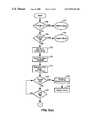
- FIGS. 5 ( a ) and 5 ( b )are a flowchart for the transmitting applications driver utilized in the practice of the present invention.
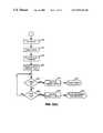
- FIGS. 6 ( a ) and 6 ( b )are a flowchart for the receiving applications driver utilized in the practice of the present invention.
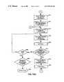
- FIGS. 7 ( a ) through 7 ( e )are a flow chart for control of the initiating CDPD modem as utilized in the practice of the present invention.
- FIGS. 8 ( a ) through 8 ( d )are a flow chart for control of the receiving CDPD modem as utilized in the practice of the present invention.
- a monitoring device 10retrieves information from a remote device, such as meter 12 .
- the informationis normally collected as an analog signal that is converted to a digital format and subsequently transmitted via wired RS232 interfaces 14 to a computing device 16 such as a computer, programmable logic controller or data concentrators/multiplexers for storage and processing.
- FIG. 1 ( b )illustrates a data transmission system utilizing the present invention.
- Datais retrieved from remote device 12 by monitoring device 10 and transmitted to a CDPD modem 18 via RS232 interfaces 14 .
- CDPD modem 18transmits the information via cellular radio to a second CDPD modem 18 ′ which, in turn, transmits the information via RS232 interfaces 14 to computing device 16 .
- a plurality of information collecting and receiving devices 13are connected to CDPD modems 18 via RS232 interfaces 14 .
- Information collected by devices 13is transmitted via CDPD modems 18 to one or more CDPD modems 18 ′ as described in greater detail below and information is transmitted to modems 18 from modems 18 ′ as indicated.
- the information received by modems 18 ′is sorted and transmitted via RS232 serial interfaces 14 to selected receiving units 17 .
- Receiving units 17may be programmable logic controllers, video displays, recorders, process control computers, data storage devices and the like.
- Receiving units 17may communicate with devices 13 via CDPD modems 18 to transmit to confirm communications, acknowledge receipt of communications and send instructions.
- Receiving units 17may utilize different protocols and standards; however, since the information is being communicated as serial data via standard RS232 interfaces, the differences in protocols and standards does not require additional resources and software for effective and reliable communications.
- the overall operation of the systemis controlled and monitored by a supervisory processing unit 23 .
- the supervisory unit 23may provide a number of functional features including monitoring the communications between the different units, directing the flow of information, controlling the priority of communications between the units and providing any additional resources required to insure compatible communications between the units.
- the CDPD modem 18includes a Subscriber Identity Module (“SIM”) 1 20 , a Mobile Application Subsystem (“MAS”) 2 22 and a Subscriber Unit (“SU”) 2 24 .
- the mobile application substation 22interfaces with the end user application and the subscriber unit 24 manages the air interface.
- the SIMis a “smart” card that is inserted or installed in a cellular phone that contains all subscriber-related information.
- the SIMfacilitates communications from a valid cellular telephone because the subscriber data is used to complete telephone communications rather than the internal serial number of the telephone.
- the present inventionprovides an enhancement to the SIM with a standard RS232 interface that increases the distance that digital data can reliably and accurately be transmitted via cellular communications and supports multiple standards without modification.
- FIG. 3is a tabular illustration of the configuration of two of the RS232 interface lines or pins utilized to implement data transmission in accordance with the present invention.
- the initiating applicationsets a “high” signal on a first line 26 .
- the program in the modem on the initiation side of the transmissiondecodes the signal and sets the status of the line in the line entry of the table to “SEND” and the value of the line to “HIGH.”
- the entire table 26is transmitted by the modem 18 on the initiating side as one packet of data.
- the receiving modemWhen the receiving modem receives the packet, it changes the status of the entry for the first line in the table to “established” on the RS232 interface.
- the receiving applicationmust then acknowledge the signal by setting the second line 28 “HIGH” in the same sequence, i.e., set the status, and transmit the table as one packet to the receiving modem.
- the initiating applicationsets the status to “ESTABLISHED” on the RS232 interface. When both lines are seen as high and established by the initiating application, the initiating modem starts data transmission.
- the data to be transmittedis concatenated to a signaling packet on the initiating side and the packet is transmitted. Since both lines are “HIGH” and “ESTABLISHED,” the receiving modem accepts the data. A Cyclical Redundancy Check (“CRC”) is used by the receiving modem to confirm the validity of the data. If the data passes the CRC check, it is accepted as valid. Since the wireless modems 18 and 18 ′ provide wireless error correction, duplication of this function is not required. Incorporation of the CRC, however, makes error checking consistent between a wired and wireless application. Through the combination of a minimal logic set and a minimal set of signaling data as set forth above the present invention provides transparency of the wireless link to the application, the same reliability as a wired link for the application and a minimal program size that is important for such applications.
- CRCCyclical Redundancy Check
- FIG. 4the timing of the sequence of steps in data transmission utilizing the present invention is schematically illustrated.
- the RTS lineis pulled “HIGH” on the RS232 interface on the initiating side.
- the CTS line on the RS232 interfaceis pulled “HIGH” after receipt of the table 26 .
- the table 26has been transmitted back to the initiating modem 18 as described above, data transmission commences.
- the receiving applicationdetects the end of text in the data, it sets the signal “LOW” on the CTS line, and initiates the same sequence of signaling to de-establish the lines.
- FIGS. 5 ( a ) and 5 ( b )are a flowchart for the applications driver for the initiating modem.
- the first stepis to check the status of the RS232 interface (step 102 ). If the port is busy, a busy signal is returned to the application (step 104 ). If the port is not busy, the application checks to determine whether the RTS line is high (step 106 ). If the RTS line is set high, a busy signal is returned to the application (step 108 ). If the RTS line is not set high, the port status is set busy (step 110 ) and the RTS line is set high and table 30 is transmitted as described above (step 112 ). A timer is initiated (step 114 ).
- the port statusis set to “ERROR” and the error status is returned to the application (steps 116 and 118 ). If the table 26 is received by the initiating application with the CTS line set high, the timers are reset (step 124 ) and data transmission is initiated.
- the receiving applicationWhen the receiving application detects the end of text in the data transmission it initiates a timer (step 128 ). If the application receives a CTS “LOW” before the timer times out, the timers are reset (step 130 ) and the RTS line is set low (step 132 ). If the timer times out before the CTS “LOW” is received, the port status is set to “ERROR” (step 134 ) and the error status is returned to the initiating application (step 136 ). Assuming that the RTS “LOW” signal is confirmed by the initiating device before the timer is timed out, the port status is set open (step 139 ) and a signal indicating successful transmission is transmitted to the initiating application (step 141 ). If the RTS low is not confirmed prior to the timer timing out, the port status is set to “ERROR” (step 142 ) and the error status is transmitted to the initiating application (step 144 ).
- FIGS. 6 ( a ) and 6 ( b )a flowchart for the applications driver for the receiving application is illustrated.
- the status of the portis checked (step 200 ) and if the port is busy a return busy signal is returned to the application (step 202 ). If the RTS line is set low, a return “IDLE” signal is returned to the application (step 204 ). If the RTS line is set “HIGH” the port status is set “BUSY” (step 206 ), the CTS line is set high (step 208 ), and table 26 is transmitted to the initiating application.
- a timeris initiated (step 210 ) and if a data transmission is detected on the port before the timer times out, the data is read (step 214 ) and the timer reset (step 216 ). If no data transmission is detected on the port before the timer times out, an error signal is returned to the application (step 212 ).
- the receiving applicationAfter the receiving application detects the end of text in the data, it sets the signal in the CTS line “LOW”, transmits the data in table 26 (step 218 ) as described above to the initiating application and sets a timer (step 220 ). If the receiving application receives confirmation that the RTS line is set low prior to timing out, the port status is set as “OPEN” (step 222 ) and a successful data receive signal is returned to the initiating application (step 224 ). If confirmation is not received, and if the timer has timed out, the port status is set to “ERROR” (step 226 ) and a return error signal is transmitted to the initiating application (step 228 ).
- FIGS. 7 ( a ), through 7 ( e )a flow chart for the CDPD modem control for the initiating modem is illustrated.
- the status of the RTS lineis checked (step 300 ), and if the RTS line is set high the status of the RTS line is mapped as “SEND” in the application buffer (step 302 ) and the application buffer is copied to the communications transmit buffer (step 304 ).
- the transmit bufferis then transmitted to the receiving modem as a UDP (“User Data Protocol”) message, (step 306 ) and a timer is set (step 308 ).
- UDPUser Data Protocol
- the receive bufferis copied to the application buffer (step 312 ) and the timer is reset (step 314 ). If the timer times out prior to the receipt of a message from the receiving modem (step 316 ) the number of attempted transmissions is compared to a predetermined maximum number of transmissions (step 318 ). If the number of attempted transmissions exceeds the predetermined maximum an error message is returned to the application (step 320 ).
- the status of the RTS and CTS lines in the application bufferis checked (step 322 ). If the RTS line status is set to “ESTABLISHED” and the CTS line status is set to “SEND”, the predetermined number of permissible transmission attempts is reset (step 324 ) and the CTS line is set high (step 326 ), otherwise control is returned to step 306 .
- the datais read from the data line into the application buffer (step 328 ) and the CTS line status is set as “ESTABLISHED” in the application buffer (step 330 ).
- the application bufferis copied to the transmit buffer (step 332 ), transmitted as a UDP message (step 334 ) and a timer is set (step 336 ).
- step 338If a message is received from the receiving modem in the receiving buffer (step 338 ), before the timer times out, the contents of the receiving buffer are copied into the applications buffer (step 340 ). If the timer times out prior to the receipt of a message from the receiving modem (step 342 ), the number of attempted transmissions are compared to a predetermined maximum number of transmissions (step 344 ).
- step 334If the number of attempted transmissions exceeds the predetermined maximum, an error message is returned to the application, otherwise control is returned to step 334 .
- the timeris reset and the line status in the application buffer are checked for RTS “ESTABLISHED” and CTS “LOW” (step 344 ). If these conditions are met, the CTS line is set low (step 346 ). If the line status in the application buffer for RTS is not “ESTABLISHED” or if CTS is not set low, control is returned to step 334 .
- the RTS lineis checked for a “HIGH” condition (step 348 ) and the maximum number of permissible attempted number of attempted transmissions is reset (step 350 ). If the RTS is “LOW,” control is returned to step 348 . After the number of permissible attempted transmissions is reset in step 350 , the line status for RTS in the applications buffer is set low (step 352 ). The applications buffer is copied to the transmit buffer (step 354 ), the transmit buffer is transmitted as a UDP message (step 356 ) and a timer is set (step 358 ).
- step 360If a message is received from the receiving modem in the receiving buffer (step 360 ) prior to the timer timing out (step 362 ), the contents of the receiving buffer are copied into the application buffer (step 364 ) and the timer is reset (step 366 ). If the timer times out (step 362 ) the number of attempted transmissions is compared to the maximum permissible number (step 368 ). If the number of attempted transmissions exceeds the maximum permissible number, an error message is returned to the application, (step 370 ); if not, control is returned to step 356 .
- step 366the line status in the applications buffer is checked for RTS “LOW” and CTS “LOW” (step 372 ). If these conditions are not met, control is returned to step 354 ; if the conditions are met, a signal indicating a successful transmission is returned to the application (step 374 ).
- the receiving modemchecks to determine whether the modem is in use (step 400 ) and if so, signals a return (step 402 ). If the modem is not in use, the application checks for a new message in the receive buffer (step 404 ). If a message is present in the receive buffer, the contents of the receive buffer are copied (step 406 ) to the applications buffer and the line status is checked for RTS “SEND” and CTS “LOW” (step 408 ). If these conditions are met, the RTS line is set “HIGH” (step 410 ) and the status of the CTS line is checked for a “HIGH” status (step 412 ).
- the line status in the applications bufferis set as RTS “ESTABLISHED” and CTS “SEND” (step 414 ).
- the contents of the application bufferare copied to the transmit buffer (step 416 ) and transmitted to the initiating modem (step 418 ) as a UDP message.
- a timeris set (step 420 ) and the receive buffer is checked for receipt of a message from the transmitting modem (step 422 ). If a message is received from the transmitting modem before the timer times out (step 424 ), the message is copied from the receive buffer into the applications buffer (step 426 ).
- step 428the timer has timed out and the number of attempted transmission has exceeded the predetermined maximum number of allowable attempted transmissions, (step 428 ), a error signal is returned to the application (step 430 ). If the timer has not timed out, control is returned to step 422 , or if the timer has timed out and the predetermined maximum number of attempted transmissions has not been 110 exceeded, control is returned to step 418 .
- the timeris reset (step 432 ) and the line status is checked for RTS “ESTABLISHED” and CTS “ESTABLISHED” (step 434 ). Data from the dataline is written to from the dataline on the port to the application (step 436 ).
- the status of the CTSis check for “LOW” (step 438 ) and if this condition is met, the predetermined allowable number of attempted transmissions is reset, (step 440 ) and the CTS status is set to “low” in the applications buffer, and the contents of the applications buffer is copied to the transmit buffer for transmission as a UDP message (step 444 ), a timer is set (step 446 ) and the receive buffer is monitored for receipt of a message from the transmitting modem (step 448 ).
- step 450the number of attempted transmissions is compared to the predetermined allowable number of attempted transmissions (step 452 ) and if the maximum allowable number of attempted transmissions is exceeded, an error signal is returned to the application (step 454 ).
- step 448After a message has been received from the transmitting modem, (step 448 ), a copy of the received buffer is copied to the application buffer, (step 456 ) and the line status is checked for CTS “LOW” and RTS “LOW” (step 458 ). If these conditions are met, the contents of the transmit buffer are transmitted (step 460 ) and a “SUCCESSFUL RECEIVE” message is returned to the application. If the line status conditions are not met, control is returned to step 446 .
- the present inventionprovides a transparent wireless link between RS232 interfaces with the same or equivalent reliability as a hard wired link. Further, the present invention provides these features with a minimal program size, a feature that is important in the applications of interest.
Landscapes
- Engineering & Computer Science (AREA)
- Computer Networks & Wireless Communication (AREA)
- Signal Processing (AREA)
- Communication Control (AREA)
Abstract
Description
Claims (23)
Priority Applications (1)
| Application Number | Priority Date | Filing Date | Title |
|---|---|---|---|
| US08/947,579US6934551B1 (en) | 1997-10-09 | 1997-10-09 | Method for wireless data transmission for adaptive multiple protocols |
Applications Claiming Priority (1)
| Application Number | Priority Date | Filing Date | Title |
|---|---|---|---|
| US08/947,579US6934551B1 (en) | 1997-10-09 | 1997-10-09 | Method for wireless data transmission for adaptive multiple protocols |
Publications (1)
| Publication Number | Publication Date |
|---|---|
| US6934551B1true US6934551B1 (en) | 2005-08-23 |
Family
ID=34839132
Family Applications (1)
| Application Number | Title | Priority Date | Filing Date |
|---|---|---|---|
| US08/947,579Expired - Fee RelatedUS6934551B1 (en) | 1997-10-09 | 1997-10-09 | Method for wireless data transmission for adaptive multiple protocols |
Country Status (1)
| Country | Link |
|---|---|
| US (1) | US6934551B1 (en) |
Cited By (8)
| Publication number | Priority date | Publication date | Assignee | Title |
|---|---|---|---|---|
| US20050250485A1 (en)* | 1997-10-09 | 2005-11-10 | George Kuriyan | Cellular-based communications system and method of using same |
| US20060133327A1 (en)* | 2003-01-06 | 2006-06-22 | Gunnar Nitsche | Method and communication device for expanding the range of data transmission rates in wireless local area networks |
| US7197330B1 (en)* | 2000-03-14 | 2007-03-27 | Intel Corporation | Dual port wireless modem for circuit switched and packet switched data transfer |
| CN102065486A (en)* | 2009-11-17 | 2011-05-18 | 美国博通公司 | Communication method and system |
| CN102065521A (en)* | 2009-11-17 | 2011-05-18 | 美国博通公司 | Communication method and communication system |
| CN102065582A (en)* | 2009-11-17 | 2011-05-18 | 美国博通公司 | Communication method and communication system |
| CN102065579A (en)* | 2009-11-17 | 2011-05-18 | 美国博通公司 | Communication method and communication system |
| US20110117944A1 (en)* | 2009-11-17 | 2011-05-19 | Yaxin Cao | Method and system for task-level access arbitration between virtual modems in a multi-sim multi-standby communication device |
Citations (18)
| Publication number | Priority date | Publication date | Assignee | Title |
|---|---|---|---|---|
| US4694473A (en)* | 1985-03-08 | 1987-09-15 | Oki Electric Industry Co., Ltd. | Data communication system with block synchronization data in mobile radio |
| US4982325A (en)* | 1988-03-18 | 1991-01-01 | At&T Bell Laboratories | Applications processor module for interfacing to a database system |
| USRE34034E (en)* | 1985-10-11 | 1992-08-18 | Spectrum Information Technologies, Inc. | Cellular telephone data communication system and method |
| US5454024A (en)* | 1989-08-31 | 1995-09-26 | Lebowitz; Mayer M. | Cellular digital packet data (CDPD) network transmission system incorporating cellular link integrity monitoring |
| US5533019A (en)* | 1994-01-31 | 1996-07-02 | Motorola, Inc. | Packet data in an analog cellular radiotelephone system |
| US5533029A (en)* | 1993-11-12 | 1996-07-02 | Pacific Communication Sciences, Inc. | Cellular digital packet data mobile data base station |
| US5535336A (en)* | 1990-09-19 | 1996-07-09 | Intel Corporation | Apparatus and method for enabling a network interface to dynamically assign an address to a connected computer and to establish a virtual circuit with another network interface |
| US5548586A (en)* | 1994-08-12 | 1996-08-20 | Nec Corporation | Mobile packet communication system and a method of mobile packet communication |
| US5711008A (en)* | 1995-03-01 | 1998-01-20 | Northern Telecom Limited | Cellular packet data arrangement |
| US5870722A (en)* | 1995-09-22 | 1999-02-09 | At&T Wireless Services Inc | Apparatus and method for batch processing of wireless financial transactions |
| US5878036A (en)* | 1995-12-20 | 1999-03-02 | Spartz; Michael K. | Wireless telecommunications system utilizing CDMA radio frequency signal modulation in conjunction with the GSM A-interface telecommunications network protocol |
| US5884146A (en)* | 1993-05-27 | 1999-03-16 | Caterpillar Inc. | Apparatus and method for establishing a radio frequency communications link between a controller and a remote controllable system |
| US5903849A (en)* | 1993-11-30 | 1999-05-11 | Nokia Mobile Phones Ltd. | Adapter for data transmission to and from a radio telephone |
| US5999798A (en)* | 1996-02-13 | 1999-12-07 | Primax Electronics, Inc. | Computer peripheral device with circuit for wirelessly receiving and transmitting signals |
| US6014569A (en)* | 1997-03-05 | 2000-01-11 | At&T Corp. | Mobile interactive radio |
| US6154600A (en)* | 1996-08-06 | 2000-11-28 | Applied Magic, Inc. | Media editor for non-linear editing system |
| US6195564B1 (en)* | 1997-09-19 | 2001-02-27 | Ericsson Inc. | Method for automatically establishing a wireless link between a wireless modem and a communication device |
| USRE37141E1 (en)* | 1984-09-10 | 2001-04-17 | Spectrum Information Technologies, Inc. | Cellular telephone data communication system and method |
- 1997
- 1997-10-09USUS08/947,579patent/US6934551B1/ennot_activeExpired - Fee Related
Patent Citations (19)
| Publication number | Priority date | Publication date | Assignee | Title |
|---|---|---|---|---|
| USRE37141E1 (en)* | 1984-09-10 | 2001-04-17 | Spectrum Information Technologies, Inc. | Cellular telephone data communication system and method |
| US4694473A (en)* | 1985-03-08 | 1987-09-15 | Oki Electric Industry Co., Ltd. | Data communication system with block synchronization data in mobile radio |
| USRE34034E (en)* | 1985-10-11 | 1992-08-18 | Spectrum Information Technologies, Inc. | Cellular telephone data communication system and method |
| US4982325A (en)* | 1988-03-18 | 1991-01-01 | At&T Bell Laboratories | Applications processor module for interfacing to a database system |
| US5454024A (en)* | 1989-08-31 | 1995-09-26 | Lebowitz; Mayer M. | Cellular digital packet data (CDPD) network transmission system incorporating cellular link integrity monitoring |
| US5535336A (en)* | 1990-09-19 | 1996-07-09 | Intel Corporation | Apparatus and method for enabling a network interface to dynamically assign an address to a connected computer and to establish a virtual circuit with another network interface |
| US5884146A (en)* | 1993-05-27 | 1999-03-16 | Caterpillar Inc. | Apparatus and method for establishing a radio frequency communications link between a controller and a remote controllable system |
| US5533029A (en)* | 1993-11-12 | 1996-07-02 | Pacific Communication Sciences, Inc. | Cellular digital packet data mobile data base station |
| US6122527A (en)* | 1993-11-12 | 2000-09-19 | Adc Telecommuncations, Inc. | Cellular digital packet data mobile data base station |
| US5903849A (en)* | 1993-11-30 | 1999-05-11 | Nokia Mobile Phones Ltd. | Adapter for data transmission to and from a radio telephone |
| US5533019A (en)* | 1994-01-31 | 1996-07-02 | Motorola, Inc. | Packet data in an analog cellular radiotelephone system |
| US5548586A (en)* | 1994-08-12 | 1996-08-20 | Nec Corporation | Mobile packet communication system and a method of mobile packet communication |
| US5711008A (en)* | 1995-03-01 | 1998-01-20 | Northern Telecom Limited | Cellular packet data arrangement |
| US5870722A (en)* | 1995-09-22 | 1999-02-09 | At&T Wireless Services Inc | Apparatus and method for batch processing of wireless financial transactions |
| US5878036A (en)* | 1995-12-20 | 1999-03-02 | Spartz; Michael K. | Wireless telecommunications system utilizing CDMA radio frequency signal modulation in conjunction with the GSM A-interface telecommunications network protocol |
| US5999798A (en)* | 1996-02-13 | 1999-12-07 | Primax Electronics, Inc. | Computer peripheral device with circuit for wirelessly receiving and transmitting signals |
| US6154600A (en)* | 1996-08-06 | 2000-11-28 | Applied Magic, Inc. | Media editor for non-linear editing system |
| US6014569A (en)* | 1997-03-05 | 2000-01-11 | At&T Corp. | Mobile interactive radio |
| US6195564B1 (en)* | 1997-09-19 | 2001-02-27 | Ericsson Inc. | Method for automatically establishing a wireless link between a wireless modem and a communication device |
Cited By (20)
| Publication number | Priority date | Publication date | Assignee | Title |
|---|---|---|---|---|
| US20050250485A1 (en)* | 1997-10-09 | 2005-11-10 | George Kuriyan | Cellular-based communications system and method of using same |
| US8213392B2 (en)* | 1997-10-09 | 2012-07-03 | Mci Communications Corporation | Cellular-based communications system and method of using same |
| US7197330B1 (en)* | 2000-03-14 | 2007-03-27 | Intel Corporation | Dual port wireless modem for circuit switched and packet switched data transfer |
| US20060133327A1 (en)* | 2003-01-06 | 2006-06-22 | Gunnar Nitsche | Method and communication device for expanding the range of data transmission rates in wireless local area networks |
| US7330455B2 (en)* | 2003-01-06 | 2008-02-12 | Philips Semiconductors Dresden Ag | Method and communication device for expanding the range of data transmission rates in wireless local area networks |
| US20110117962A1 (en)* | 2009-11-17 | 2011-05-19 | Xiaoxin Qiu | Method and system for multi-standby operation for a multi-sim multi-standby communication device |
| US20110117965A1 (en)* | 2009-11-17 | 2011-05-19 | Zhijun Gong | Method and system for task scheduling in an operating system for virtual modems within a multi-sim multi-standby communication device |
| CN102065579A (en)* | 2009-11-17 | 2011-05-18 | 美国博通公司 | Communication method and communication system |
| US20110117944A1 (en)* | 2009-11-17 | 2011-05-19 | Yaxin Cao | Method and system for task-level access arbitration between virtual modems in a multi-sim multi-standby communication device |
| US20110117909A1 (en)* | 2009-11-17 | 2011-05-19 | Yaxin Cao | Method and system for dynamically selecting and configuring virtual modems (vms) based on performance metrics in a multi-sim multi-standby communication device |
| CN102065521A (en)* | 2009-11-17 | 2011-05-18 | 美国博通公司 | Communication method and communication system |
| US20110117963A1 (en)* | 2009-11-17 | 2011-05-19 | Yongqian Wang | Method and system for a fast cell recovery on suspended virtual modems within a multi-sim multi-standby communication device |
| CN102065582A (en)* | 2009-11-17 | 2011-05-18 | 美国博通公司 | Communication method and communication system |
| CN102065486A (en)* | 2009-11-17 | 2011-05-18 | 美国博通公司 | Communication method and system |
| CN102065582B (en)* | 2009-11-17 | 2014-07-30 | 美国博通公司 | Communication method and communication system |
| US8874167B2 (en)* | 2009-11-17 | 2014-10-28 | Broadcom Corporation | Method and system for multi-standby operation for a multi-SIM multi-standby communication device |
| TWI468059B (en)* | 2009-11-17 | 2015-01-01 | Broadcom Corp | Method and system for multi-standby operation for a multi-sim multi-standby communication device |
| TWI474695B (en)* | 2009-11-17 | 2015-02-21 | Broadcom Corp | Method and system for a fast cell recovery on suspended virtual modems within a multi-sim multi-standby communication device |
| CN102065579B (en)* | 2009-11-17 | 2015-06-17 | 美国博通公司 | Communication method and communication system |
| US9072035B2 (en)* | 2009-11-17 | 2015-06-30 | Broadcom Corporation | Method and system for task mapping based on corresponding virtual modem identifiers in an operating system for virtual modems within a multi-SIM multi-standby communication device |
Similar Documents
| Publication | Publication Date | Title |
|---|---|---|
| US7266094B2 (en) | Wireless data interface system for fixed point-to-point communications | |
| US5555241A (en) | Method and apparatus for maximizing the data transmission in a wireless data communication network | |
| US6507590B1 (en) | Method of data transfer and data interface unit | |
| KR100336810B1 (en) | Packet Data Protocol for Wireless Communication | |
| US5559800A (en) | Remote control of gateway functions in a wireless data communication network | |
| US4680773A (en) | Data telecommunications system and method utilizing a multi-mode modem | |
| US5191583A (en) | Method and apparatus for effecting efficient transmission of data | |
| USH1880H (en) | System and method for processing wireless voice and data telecommunications | |
| CN101442481A (en) | Dual proxy approach to TCP performance improvements over a wireless interface | |
| CA1223650A (en) | Data communication method and circuitry | |
| US6934551B1 (en) | Method for wireless data transmission for adaptive multiple protocols | |
| CN1545791B (en) | Mobile communication system, equipment and method for updating state information in data trasmission | |
| US8213392B2 (en) | Cellular-based communications system and method of using same | |
| US6278696B1 (en) | Communication method and apparatus | |
| KR20020038943A (en) | Synchronization method and apparatus | |
| CN101572716A (en) | Method for transmitting small computer system interface (SCSI) packet and device thereof | |
| CN114938239A (en) | Heaven-earth satellite voice data transmission terminal device and data transmission method | |
| KR100467290B1 (en) | SMS system and method using TCP/IP based on Wireless Internet | |
| US20060258381A1 (en) | Method and apparatus for transmitting digital data | |
| KR100281974B1 (en) | Method and apparatus for handling a frame of an exchange | |
| CN111431842A (en) | Serial port terminal wireless transmission method for private network environment | |
| JP2814497B2 (en) | Signal link control device | |
| US20090046685A1 (en) | Method and System for a Wireless Transmission over GPRS Communications Network | |
| KR0168907B1 (en) | Apparatus and method of control of system access between wireless paging data transmission earth station system and network managing system | |
| KR100810372B1 (en) | In a digital signal processing unit of a communication system, |
Legal Events
| Date | Code | Title | Description |
|---|---|---|---|
| AS | Assignment | Owner name:MCI COMMUNICATIONS CORPORATION, DISTRICT OF COLUMB Free format text:ASSIGNMENT OF ASSIGNORS INTEREST;ASSIGNOR:KURIYAN, GEORGE;REEL/FRAME:008767/0107 Effective date:19971008 | |
| REFU | Refund | Free format text:REFUND - SURCHARGE FOR LATE PAYMENT, LARGE ENTITY (ORIGINAL EVENT CODE: R1554); ENTITY STATUS OF PATENT OWNER: LARGE ENTITY Free format text:REFUND - PAYMENT OF MAINTENANCE FEE, 4TH YEAR, LARGE ENTITY (ORIGINAL EVENT CODE: R1551); ENTITY STATUS OF PATENT OWNER: LARGE ENTITY | |
| FPAY | Fee payment | Year of fee payment:4 | |
| FPAY | Fee payment | Year of fee payment:8 | |
| AS | Assignment | Owner name:VERIZON PATENT AND LICENSING INC., NEW JERSEY Free format text:ASSIGNMENT OF ASSIGNORS INTEREST;ASSIGNOR:MCI COMMUNICATIONS CORPORATION;REEL/FRAME:032725/0001 Effective date:20140409 | |
| AS | Assignment | Owner name:VERIZON PATENT AND LICENSING INC., NEW JERSEY Free format text:CORRECTIVE ASSIGNMENT TO REMOVE THE PATENT NUMBER 5,835,907 PREVIOUSLY RECORDED ON REEL 032725 FRAME 0001. ASSIGNOR(S) HEREBY CONFIRMS THE ASSIGNMENT;ASSIGNOR:MCI COMMUNICATIONS CORPORATION;REEL/FRAME:033408/0235 Effective date:20140409 | |
| REMI | Maintenance fee reminder mailed | ||
| LAPS | Lapse for failure to pay maintenance fees | Free format text:PATENT EXPIRED FOR FAILURE TO PAY MAINTENANCE FEES (ORIGINAL EVENT CODE: EXP.) | |
| STCH | Information on status: patent discontinuation | Free format text:PATENT EXPIRED DUE TO NONPAYMENT OF MAINTENANCE FEES UNDER 37 CFR 1.362 | |
| FP | Lapsed due to failure to pay maintenance fee | Effective date:20170823 |