US6934459B2 - Reel to reel manufacturing line - Google Patents
Reel to reel manufacturing lineDownload PDFInfo
- Publication number
- US6934459B2 US6934459B2US10/276,901US27690103AUS6934459B2US 6934459 B2US6934459 B2US 6934459B2US 27690103 AUS27690103 AUS 27690103AUS 6934459 B2US6934459 B2US 6934459B2
- Authority
- US
- United States
- Prior art keywords
- fiber
- line
- reel
- optical fiber
- measurement means
- Prior art date
- Legal status (The legal status is an assumption and is not a legal conclusion. Google has not performed a legal analysis and makes no representation as to the accuracy of the status listed.)
- Expired - Lifetime, expires
Links
- 238000004519manufacturing processMethods0.000titledescription16
- 239000000835fiberSubstances0.000claimsabstractdescription129
- 239000013307optical fiberSubstances0.000claimsabstractdescription60
- 238000005259measurementMethods0.000claimsabstractdescription53
- 238000000034methodMethods0.000claimsabstractdescription49
- 238000001228spectrumMethods0.000claimsabstractdescription23
- 238000004804windingMethods0.000claimsabstractdescription20
- 238000012545processingMethods0.000claimsabstractdescription17
- 230000005855radiationEffects0.000claimsabstractdescription17
- 230000003287optical effectEffects0.000claimsdescription48
- 230000010287polarizationEffects0.000claimsdescription13
- 238000000137annealingMethods0.000claimsdescription8
- 238000007689inspectionMethods0.000claimsdescription8
- 238000004140cleaningMethods0.000claimsdescription7
- 239000011248coating agentSubstances0.000claimsdescription7
- 238000000576coating methodMethods0.000claimsdescription7
- 239000006185dispersionSubstances0.000claimsdescription6
- 238000000411transmission spectrumMethods0.000claimsdescription5
- 238000003908quality control methodMethods0.000description5
- 230000002950deficientEffects0.000description3
- 238000012856packingMethods0.000description3
- 238000005424photoluminescenceMethods0.000description3
- 238000012360testing methodMethods0.000description3
- 230000001133accelerationEffects0.000description2
- 238000003491arrayMethods0.000description2
- 230000005540biological transmissionEffects0.000description2
- 238000005520cutting processMethods0.000description2
- 230000007547defectEffects0.000description2
- 230000033001locomotionEffects0.000description2
- 239000003550markerSubstances0.000description2
- 238000012986modificationMethods0.000description2
- 230000004048modificationEffects0.000description2
- 238000012544monitoring processMethods0.000description2
- 238000004886process controlMethods0.000description2
- 230000001360synchronised effectEffects0.000description2
- 238000013519translationMethods0.000description2
- UFHFLCQGNIYNRP-UHFFFAOYSA-NHydrogenChemical compound[H][H]UFHFLCQGNIYNRP-UHFFFAOYSA-N0.000description1
- 238000011109contaminationMethods0.000description1
- 238000001514detection methodMethods0.000description1
- 230000000694effectsEffects0.000description1
- 239000007789gasSubstances0.000description1
- 239000003365glass fiberSubstances0.000description1
- 239000001257hydrogenSubstances0.000description1
- 229910052739hydrogenInorganic materials0.000description1
- 239000011261inert gasSubstances0.000description1
- 238000013507mappingMethods0.000description1
- 238000005457optimizationMethods0.000description1
- 239000011253protective coatingSubstances0.000description1
- 230000035945sensitivityEffects0.000description1
- 239000002904solventSubstances0.000description1
- 239000000126substanceSubstances0.000description1
- 238000010408sweepingMethods0.000description1
- 238000010998test methodMethods0.000description1
- 238000011179visual inspectionMethods0.000description1
Images


Classifications
- G—PHYSICS
- G02—OPTICS
- G02B—OPTICAL ELEMENTS, SYSTEMS OR APPARATUS
- G02B6/00—Light guides; Structural details of arrangements comprising light guides and other optical elements, e.g. couplings
- G02B6/44—Mechanical structures for providing tensile strength and external protection for fibres, e.g. optical transmission cables
- G02B6/4479—Manufacturing methods of optical cables
- B—PERFORMING OPERATIONS; TRANSPORTING
- B65—CONVEYING; PACKING; STORING; HANDLING THIN OR FILAMENTARY MATERIAL
- B65H—HANDLING THIN OR FILAMENTARY MATERIAL, e.g. SHEETS, WEBS, CABLES
- B65H49/00—Unwinding or paying-out filamentary material; Supporting, storing or transporting packages from which filamentary material is to be withdrawn or paid-out
- B65H49/02—Methods or apparatus in which packages do not rotate
- B—PERFORMING OPERATIONS; TRANSPORTING
- B65—CONVEYING; PACKING; STORING; HANDLING THIN OR FILAMENTARY MATERIAL
- B65H—HANDLING THIN OR FILAMENTARY MATERIAL, e.g. SHEETS, WEBS, CABLES
- B65H54/00—Winding, coiling, or depositing filamentary material
- B65H54/02—Winding and traversing material on to reels, bobbins, tubes, or like package cores or formers
- B65H54/28—Traversing devices; Package-shaping arrangements
- B65H54/2896—Flyers
- B—PERFORMING OPERATIONS; TRANSPORTING
- B65—CONVEYING; PACKING; STORING; HANDLING THIN OR FILAMENTARY MATERIAL
- B65H—HANDLING THIN OR FILAMENTARY MATERIAL, e.g. SHEETS, WEBS, CABLES
- B65H57/00—Guides for filamentary materials; Supports therefor
- B65H57/18—Guides for filamentary materials; Supports therefor mounted to facilitate unwinding of material from packages
- B65H57/20—Flyers
- G—PHYSICS
- G02—OPTICS
- G02B—OPTICAL ELEMENTS, SYSTEMS OR APPARATUS
- G02B6/00—Light guides; Structural details of arrangements comprising light guides and other optical elements, e.g. couplings
- G02B6/02—Optical fibres with cladding with or without a coating
- G02B6/02057—Optical fibres with cladding with or without a coating comprising gratings
- G02B6/02076—Refractive index modulation gratings, e.g. Bragg gratings
- G02B6/02123—Refractive index modulation gratings, e.g. Bragg gratings characterised by the method of manufacture of the grating
- G02B6/02152—Refractive index modulation gratings, e.g. Bragg gratings characterised by the method of manufacture of the grating involving moving the fibre or a manufacturing element, stretching of the fibre
- B—PERFORMING OPERATIONS; TRANSPORTING
- B65—CONVEYING; PACKING; STORING; HANDLING THIN OR FILAMENTARY MATERIAL
- B65H—HANDLING THIN OR FILAMENTARY MATERIAL, e.g. SHEETS, WEBS, CABLES
- B65H2515/00—Physical entities not provided for in groups B65H2511/00 or B65H2513/00
- B65H2515/60—Optical characteristics, e.g. colour, light
- B—PERFORMING OPERATIONS; TRANSPORTING
- B65—CONVEYING; PACKING; STORING; HANDLING THIN OR FILAMENTARY MATERIAL
- B65H—HANDLING THIN OR FILAMENTARY MATERIAL, e.g. SHEETS, WEBS, CABLES
- B65H2701/00—Handled material; Storage means
- B65H2701/30—Handled filamentary material
- B65H2701/32—Optical fibres or optical cables
- G—PHYSICS
- G02—OPTICS
- G02B—OPTICAL ELEMENTS, SYSTEMS OR APPARATUS
- G02B6/00—Light guides; Structural details of arrangements comprising light guides and other optical elements, e.g. couplings
- G02B6/10—Light guides; Structural details of arrangements comprising light guides and other optical elements, e.g. couplings of the optical waveguide type
- G02B6/12—Light guides; Structural details of arrangements comprising light guides and other optical elements, e.g. couplings of the optical waveguide type of the integrated circuit kind
- G02B2006/12083—Constructional arrangements
- G02B2006/12107—Grating
- G—PHYSICS
- G02—OPTICS
- G02B—OPTICAL ELEMENTS, SYSTEMS OR APPARATUS
- G02B6/00—Light guides; Structural details of arrangements comprising light guides and other optical elements, e.g. couplings
- G02B6/44—Mechanical structures for providing tensile strength and external protection for fibres, e.g. optical transmission cables
- G02B6/4439—Auxiliary devices
- G02B6/4457—Bobbins; Reels
Definitions
- the present inventionrelates to a reel to reel manufacturing line for processing an optical fiber.
- the inventionseeks to provide an automated manufacturing line to write successive optical devices, such as Bragg gratings, on an optical fiber.
- the lineincludes all the required functions to provide complete final products fully characterized, including quality control, requiring only to be cut in desired length segments and to be packaged.
- any optical waveguide which could be wound on a reelcould be processed by the manufacturing line.
- the manufacturing linecomprises an apparatus for unwinding (de-winder) the optical fiber from a first reel without rotating the reel, the apparatus being located at one end of the manufacturing line.
- the de-windercan be placed in a cooled enclosure if the first reel has a hydrogen-loaded fiber wound thereon.
- the linecomprises an apparatus for winding the fiber on a second reel also without rotating the reel. This enables the connection of both ends of the fiber, which can be a few kilometers long, to optical measurement instruments. Indeed, instead of using a rotating coupler, standard couplers and connectors are used.
- a fabrication apparatuse.g. a source of optical radiation
- the fabrication apparatuscan be a fiber grating-manufacturing device (e.g. a laser), a fiber grating measurement device, a fiber sectional measurement device or a fiber coating modification device.
- the linecomprises a source of optical radiation (e.g. a laser) delivering the high energy (e.g. a beam) to write the Bragg gratings and an apparatus for aligning the fiber with the source of optical radiation.
- the apparatus for aligning the fiber with the lasercomprises a support for holding the fiber, wherein in use the support is oriented such that the beam emitted by the laser illuminates a first portion of the fiber thereby causing the fiber to emit photoluminescence and a sensor located in proximity to the fiber for detecting photoluminescence emitted radially by the fiber and generating an intensity signal indicative of a measure of the photoluminescence detected.
- the apparatusalso comprises a controller module responsive to the intensity signal for causing the beam emitted by the laser to illuminate a second portion of the fiber.
- the linemay also be used to write arrays of different gratings, at the same wavelengths or not, and by using a synchronized encoder, evenly spacing them or not along the fiber.
- Guiding devicescan be used to restrict the fiber path.
- the linecomprises functional units, such as cleaning units, a stripping unit, an annealing unit, inspection units or a recoating unit, each unit possibly comprising clamping devices to position and tension the fiber.
- the section of the fiber to be treatedis grabbed on each side by a clamping device as this section of the fiber leaves the first reel.
- the clamping deviceis mounted on a cart that is movable from one functional unit to the next one.
- the clamping devicecomprises a mechanism to adjust and monitor the tension in the grabbed section of the fiber that is used to optimize tension for each functional unit. In both cases, the different functional operations can be made one after the other or simultaneously.
- either the fibercan be moved in place and/or the specific apparatus can be brought to the fiber by pneumatic piston and/or standard optical stage for example.
- the inventionseeks to provide a line for processing an optical fiber having first and second ends, the line comprising a support for receiving a reel with the fiber wound thereon; a de-winder for unwinding the fiber without substantial rotation of the reel; and a processing station for receiving the optical fiber from said de-winder to perform a processing on a portion of the optical fiber.
- the linealso comprises a second support for receiving a second reel and a winder for winding the fiber on the second reel without rotation of the second reel.
- the linealso comprises a source of optical radiation (e.g. a laser) for writing a grating on the fiber.
- the inventionalso seeks to provide a method for processing an optical fiber having first and second ends, the fiber being wound on a first reel and being capable of being wound on a second reel, the method comprising: connecting the first end of the fiber to a source of light and a measurement means; de-winding the fiber from the first reel without substantially turning the reel; processing a portion of the fiber with a source of optical radiation; and during the process, measuring reflection spectra of the portion of the fiber with said measurement means.
- the methodfurther comprises connecting the second end of the fiber to a second measurement means and measuring transmission spectra of the portion with said second measurement means.
- the methodalso comprises winding the fiber on the second reel without substantial rotation of the reel.
- the inventionalso seeks to provide a method for performing a predetermined process on an optical fiber, comprising: providing a reel having a continuous optical fiber wound thereon, the optical fiber having a first end and a second end; unwinding the optical fiber from the reel without substantially turning the reel; introducing light via one of the first and second ends of the optical fiber such that the light propagates in the optical fiber; performing a predetermined process on a portion of the optical fiber unwound from the reel.
- the inventionalso seeks to provide a method for performing a predetermined process on an optical fiber wound on a first reel, the optical fiber having first and second ends, the method comprising: unwinding the optical fiber from the first reel substantially without rotation of the first reel to create an unwound portion; performing a predetermined process on the unwound portion; winding the unwound portion after the predetermined process has been performed on a second reel substantially without rotation of the second reel; during the predetermined process introducing light via one of the first and second ends of the optical fiber such that the light propagates to the unwound portion through a portion of the optical fiber wound on either one of the first and second reels.
- the inventionalso seeks to provide a line for measuring optical properties of gratings written on a fiber having first and second ends, the line comprising: first and second supports for receiving first and second reels, the first reel having the fiber wound thereon; a de-winder for unwinding the fiber without rotation of the reel; a winder for winding the fiber on the second reel without rotation of the second reel; a source of light connected at one of the first and second ends of the fiber; and a measurement means connected at one of the first and second ends of the fiber for measuring optical properties of the gratings.
- FIG. 1shows a process flow for a reel to reel manufacturing line for writing gratings on a fiber, the line being constructed in accordance with an embodiment of the invention
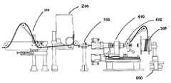
- FIG. 2shows one end of the line having a dancer arm assembly, an electronic tensioner, an air bushing, a winder and a reel mounted on a support;
- FIG. 3is a side elevational view of the dancer arm assembly of FIG. 2 ;
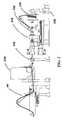
- FIG. 4is a side elevational view of the electronic tensioner of FIG. 2 ;
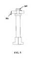
- FIG. 5is a side elevational view of the air bushing of FIG. 2 ;
- FIG. 6is a top plan view of the air bushing of FIG. 5 ;
- FIG. 7is a front elevational view of the air bushing of FIG. 5 ;
- FIG. 8is a front elevational view of the winder of FIG. 2 ;
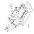
- FIG. 9is a perspective view of the winder of FIG. 8 ;
- FIG. 10is a side elevational view of the winder of FIG. 8 ;
- FIG. 11is a top plan view of the winder of FIG. 8 ;
- FIG. 12is a cross-sectional view of the rotatable arm of the winder of FIG. 8 ;
- FIG. 13is a side elevational view of the reel and support of FIG. 2 .
- FIG. 1A reel to reel manufacturing line for writing gratings on a fiber is illustrated in FIG. 1 .
- the linecomprises an apparatus for unwinding the fiber from a first reel (de-winder 1 ).
- De-winder 1is placed in a cooled container 2 to slow down out gazing from the fiber if necessary.
- the linecomprises first and second ends, the first end being connected via an optical circulator 3 to a source of light such as a broadband light source or a tunable laser 4 and a power meter 5 (or an optical spectrum analyzer) while the second end is connected to another power meter 5 (or an optical spectrum analyzer).
- a source of lightsuch as a broadband light source or a tunable laser 4 and a power meter 5 (or an optical spectrum analyzer) while the second end is connected to another power meter 5 (or an optical spectrum analyzer).
- the reflection spectrum of the created gratingscan be measured.
- the polarization dependence loss (PDL) of the created gratingscan be measured.
- the fiberpasses through a cleaning unit 6 and then trough an inspection unit 7 that marks defective segments by an ink jet marker 8 .
- the source of optical radiatione.g. a laser
- the lineincludes stripping apparatus (e.g. a mechanical stripper) 9 to remove the coating or jacket before the gratings is written.
- stripping apparatuse.g. a mechanical stripper
- different types of stripping apparatuscan be used, such as blades based equipment, hot or cold blades; thermal/energy, such as electric elements, laser or hot gas based equipment; or chemical/solvent based equipment.
- the bare glass fiber sectionis then cleaned by a cleaning unit 10 , inspected and marked if defective.
- a cleaning unit 10Several type of cleaning units such as fiber surface sweeping by soft wet tissue and/or brush, inert gas flow and electrostatic discharge can be used.
- the fiberis then guided by guiding devices 11 designed to avoid contacts with the stripped region of the fiber until the latter leaves a recoating unit 14 .
- a processing stationsuch as a source of optical radiation (e.g. a laser or holoscope) 12 , it is grabbed on each coated side by tensioning clamps (e.g. tensioners) 13 .
- a source of optical radiatione.g. a laser or holoscope
- tensioning clampse.g. tensioners
- the spectra of the gratingscan be separated from the spectra of those previously written, enabling real time monitoring for fabrication process control.
- Moderated longitudinal tension on the fiberdoes not deform the spectra, but translates it along the wavelength axis. So, an array of even similar gratings can be made and individual spectra can be measured by tensioning longitudinally the fiber while writing and annealing, and relieving the tension for re-winding. As the longitudinal tension on the fiber is relieved, another optical measurement can be made to track the spectra's peaks translation along the wavelength axis for exact center wavelength measurement.
- the stripped region of the fibercan be put under minimal tension and the previously formed gratings can be re-wound under tension to translate same to other wavelengths.
- the stripped and written region of the fibermoves into the recoating unit 14 . If, in addition, the process includes an in-line fiber gratings annealing step, instead of an off-line batch annealing, the written region would not require further optical measurements since both ends of the fiber are connected and all the quality control can therefore be made in line.
- the recoated fiberpasses through another inspection unit 7 that marks defective segments by an ink jet marker.
- the inspectionmay be performed by visual inspection stations having for example cameras or analyzer systems. With this type of inspection, the protective coating integrity is monitored all along the fiber and in-line proof testing is possible after the recoating station to insure the fiber's mechanical (microcracks) integrity and mechanical lifetime.
- An ink jet encoder 15identifies the cutting lines and the sub-section for the automated packing line. Finally, the fiber is re-wound on a second reel by an apparatus for winding (winder 16 ), without rotation of the second reel.
- both ends of the fiberare fixed and stable all along the delivering of the fiber from the first reel to the second reel, it is possible to have a line that is compatible to any optical measurement system, regardless of the type and sensitivity of connections required. It is to be understood that multiple types of optical measurements, such as chromatic dispersion, can be used in conjunction with the line.
- All the components of the lineare controlled by a central computer that synchronizes the motions, analyzes the acquired data and controls the process, and stores all pertinent data for process monitoring and optimization in a central database. Synchronization of motions is achieved by pre-mapping, calibration and position sensors combined to a software program, running in a constant feedback loop mode, that sends parameter settings to the different functional units and movable devices.
- the in-line optical measurementsare in a constant feedback loop mode to control the parameters and the duration of the expositions in the source of optical radiation 12 during the fiber grating writing, as well as, during the fiber grating annealing.
- Results of the fiber inspection unitsare acquired by the computer and a software program analyze them to re-adjust specific functional apparatus parameters settings.
- the central computeralso controls the ink jet markers that are located all along the line.
- a bar code protocolcan be used to mark the fiber with specific messages at specific locations. These messages may include the serial number of the device, the cutting lines where the fiber should be cut later on, as well as different quality control codes for various ranges of defects.
- the bar code markscan be read in other automated lines, such as an un-winding/packing/triage automated line to obtain ready to ship products.
- the following quality control parametersare measured on the line: surface and coating defects and contamination all along the process, mechanical integrity through the in-line proof test functional unit, final and intermediary optical properties (transmission and reflection spectra, polarization dependence loss (PDL), polarization mode dispersion (PMD) and optical life expectancy through index profile decay during annealing.
- PDLpolarization dependence loss
- PMDpolarization mode dispersion
- a commercially available self-synchronized multi-ports sweep systemis used for the optical measurements.
- This systemincludes a rotational device of the polarization states that enables in line measurements of polarization dependence loss (PDL) and polarization mode dispersion (PMD) in addition to the transmission and reflection spectra.
- PDLpolarization dependence loss
- PMDpolarization mode dispersion
- Computerized data acquisition from the different elements of the linecan be used to identify the spectra, location, quality/integrity of the different gratings and parts of the array.
- the second reelcan feed an automated packing line.
- the completed manufacturing reel to reel linecan be located in an atmosphere-controlled chamber.
- the fiberpasses through a dancer arm assembly 100 , an electronic tensioner 200 , an air bushing 300 , a winder 400 having a rotatable arm 402 that turns around a reel 500 mounted on a support 600 .
- the fiberenters dancer arm assembly 100 under a first roller 102 , then passes over a second roller 104 and under a third roller 106 .
- Dancer arm assembly 100also comprises an arm 108 having second roller 104 mounted at its distal end and third roller 106 mounted adjacent its proximal end. Proximal end of arm 108 is attached to an adjustment mechanism 110 through a spring 1 12 . Spring 1 12 counter balances the force exerted by the fiber on second roller 104 . The tension of spring 112 can be adjusted by adjustment mechanism 110 .
- Third roller 106is mounted adjacent to a potentiometer 114 that reads the angular position of arm 108 . In this matter, the tension in the fiber is also read.
- tension sensorssuch as potentiometer 114
- the fiberthen passes between first and second wheels 202 , 204 mounted on electronic tensioner 200 , up and around (a full turn) a wire brake wheel also mounted on electronic tensioner 200 , then up (half a turn) and around a wire tension take-up wheel 206 .
- the fiberthen passes through air bushing 300 that serves to guide and push the fiber through winder 400 .
- the airenters by a fitting 302 , its flow being adjusted by a valve 304 , and leaves through orifice 306 .
- Winder 400also comprises a counter weight 408 .
- Winder 400further comprises a winder servomotor 410 that actuates rotatable arm 402 via a belt 412 .
- Winder servomotor 410is placed beside the fiber path and its speed is controlled by the position of arm position 108 , via potentiometer 114 .
- Winder 400further comprises a position servomotor 414 and a pair of rails 416 on which position servomotor 414 is movable.
- Winder servomotor 410is mounted on position servomotor 414 .
- the translation speed of position servomotor 414 and the rotational speed of winder servomotor 410are controlled and synchronized in order to properly wind the fiber on reel 500 .
- the present inventioncan be used on any existing grating writing process to enhance its throughput, for re-measurements of fiber grating arrays, or for many kind of measurement of properties of the fiber along its length since the de-winder and winder of the reels that de-winds and winds the fiber without its rotation enables the permanent connections of both ends of the fiber to measurement devices.
- the present inventionalso covers a line for measuring optical properties of gratings written on a fiber having first and second ends. More particularly, the line also comprises first and second supports for receiving first and second reels, the first reel having the fiber wound thereon. The line further comprises a de-winder for unwinding the fiber without rotation of the first reel and a winder for winding the fiber on the second reel without rotation of the second reel. Finally, the line comprises a source of light connected at one of the first and second ends of the fiber and a measurement means connected at one of the first and second ends of the fiber for measuring optical properties of the gratings.
Landscapes
- Physics & Mathematics (AREA)
- Engineering & Computer Science (AREA)
- Manufacturing & Machinery (AREA)
- General Physics & Mathematics (AREA)
- Optics & Photonics (AREA)
- Light Guides In General And Applications Therefor (AREA)
- Optical Fibers, Optical Fiber Cores, And Optical Fiber Bundles (AREA)
Abstract
Description
Claims (48)
Priority Applications (1)
| Application Number | Priority Date | Filing Date | Title |
|---|---|---|---|
| US11/106,168US7164841B2 (en) | 2001-07-26 | 2005-04-13 | Reel to reel manufacturing line |
Applications Claiming Priority (2)
| Application Number | Priority Date | Filing Date | Title |
|---|---|---|---|
| CA002354211ACA2354211A1 (en) | 2001-07-26 | 2001-07-26 | Reel to reel manufacturing line |
| PCT/CA2002/001183WO2003010573A2 (en) | 2001-07-26 | 2002-07-26 | Reel to reel optical fiber processing line |
Related Child Applications (1)
| Application Number | Title | Priority Date | Filing Date |
|---|---|---|---|
| US11/106,168DivisionUS7164841B2 (en) | 2001-07-26 | 2005-04-13 | Reel to reel manufacturing line |
Publications (2)
| Publication Number | Publication Date |
|---|---|
| US20040052457A1 US20040052457A1 (en) | 2004-03-18 |
| US6934459B2true US6934459B2 (en) | 2005-08-23 |
Family
ID=4169593
Family Applications (2)
| Application Number | Title | Priority Date | Filing Date |
|---|---|---|---|
| US10/276,901Expired - LifetimeUS6934459B2 (en) | 2001-07-26 | 2002-07-26 | Reel to reel manufacturing line |
| US11/106,168Expired - LifetimeUS7164841B2 (en) | 2001-07-26 | 2005-04-13 | Reel to reel manufacturing line |
Family Applications After (1)
| Application Number | Title | Priority Date | Filing Date |
|---|---|---|---|
| US11/106,168Expired - LifetimeUS7164841B2 (en) | 2001-07-26 | 2005-04-13 | Reel to reel manufacturing line |
Country Status (4)
| Country | Link |
|---|---|
| US (2) | US6934459B2 (en) |
| AU (1) | AU2002322232A1 (en) |
| CA (1) | CA2354211A1 (en) |
| WO (1) | WO2003010573A2 (en) |
Cited By (2)
| Publication number | Priority date | Publication date | Assignee | Title |
|---|---|---|---|---|
| US20140233889A1 (en)* | 2013-02-21 | 2014-08-21 | Ofs Fitel, Llc | Index matched grating inscription |
| EP3290971A1 (en) | 2016-09-02 | 2018-03-07 | National Research Council of Canada | Automated system for trans-jacket fiber bragg grating inscription and manufacturing |
Families Citing this family (9)
| Publication number | Priority date | Publication date | Assignee | Title |
|---|---|---|---|---|
| US8117725B2 (en)* | 2008-10-31 | 2012-02-21 | The Gillette Company | Method of manufacturing a plurality of molded components |
| CN107421656B (en)* | 2017-06-16 | 2018-10-09 | 武汉理工大学 | One kind exempting from stress twin-core and with temperature sensing optical fiber preparation facilities and method |
| US20220127104A1 (en)* | 2019-01-15 | 2022-04-28 | Sumitomo Electric Industries, Ltd. | Winding device and winding method |
| FI20195790A1 (en)* | 2019-09-20 | 2021-03-21 | Maillefer Extrusion Oy | MACHINE LEARNING-BASED QUALITY PREDICTION OF A MANUFACTURED OPTO FIBER CABLE |
| CN111240274B (en)* | 2020-01-15 | 2023-02-14 | 吉林大学 | Control system and control method for medium linear speed winding in non-circular winding system |
| CN113697593B (en)* | 2021-10-28 | 2022-03-18 | 江苏云洋电力科技有限公司 | Winding device for cable manufacturing and convenient for accurately controlling length of cable coil |
| CN114236673B (en)* | 2021-12-22 | 2024-12-03 | 长飞(武汉)光系统股份有限公司 | An integrated fiber Bragg grating writing system |
| CN119087567B (en)* | 2024-11-07 | 2025-02-21 | 武汉驿路通科技股份有限公司 | Grating manufacturing device |
| CN119376010B (en)* | 2024-12-26 | 2025-03-04 | 中国人民解放军国防科技大学 | Distributed fiber grating writing device and writing method based on roll-to-roll |
Citations (21)
| Publication number | Priority date | Publication date | Assignee | Title |
|---|---|---|---|---|
| GB2084618A (en) | 1980-09-25 | 1982-04-15 | Bicc Ltd | Wire pay-off |
| US5019780A (en)* | 1989-10-23 | 1991-05-28 | Hughes Aircraft Company | Method and apparatus for monitoring optical fibers during payout |
| US5066133A (en) | 1990-10-18 | 1991-11-19 | United Technologies Corporation | Extended length embedded Bragg grating manufacturing method and arrangement |
| US5156355A (en) | 1990-07-05 | 1992-10-20 | Ron Wadle | Winding and unwinding apparatus incorporating wrapping arms |
| US5377288A (en) | 1990-04-06 | 1994-12-27 | British Telecommunications Public Limited Company | Method of forming a refractive index grating in an optical waveguide |
| US5572609A (en) | 1995-09-01 | 1996-11-05 | University Of Maryland | Optical fiber vibration modal filter for flexible structures produced by the photorefractive effect |
| US5604829A (en) | 1995-04-17 | 1997-02-18 | Hughes Aircraft Company | Optical waveguide with diffraction grating and method of forming the same |
| US5745615A (en) | 1996-10-11 | 1998-04-28 | Lucent Technologies Inc. | Method of making an optical fiber grating, and article made by the method |
| WO1998018031A1 (en) | 1996-10-23 | 1998-04-30 | Minnesota Mining And Manufacturing Company | Apparatus and process for the manufacture of optical fiber bragg gratings |
| US5912999A (en) | 1997-10-02 | 1999-06-15 | Minnesota Mining And Manufacturing Company | Method for fabrication of in-line optical waveguide index grating of any length |
| US5956442A (en) | 1994-12-03 | 1999-09-21 | Northern Telecom Limited | Bragg reflection gratings in optical fibres |
| US6004703A (en) | 1997-07-21 | 1999-12-21 | Samsung Electronics Co., Ltd. | Amplitude mask and apparatus for manufacturing long period grating filter using the same |
| US6035083A (en) | 1997-10-02 | 2000-03-07 | 3M Innovative Company | Method for writing arbitrary index perturbations in a wave-guiding structure |
| US6050109A (en) | 1996-11-04 | 2000-04-18 | Lucent Technologies Inc. | Method for making long-period fiber gratings |
| US6084998A (en) | 1998-12-30 | 2000-07-04 | Alpha And Omega Imaging, Llc | System and method for fabricating distributed Bragg reflectors with preferred properties |
| US6093927A (en) | 1997-06-09 | 2000-07-25 | Trw Inc. | Automated precision wavelength control for fiber optic Bragg grating writing |
| US6160944A (en) | 1995-04-28 | 2000-12-12 | University Of Southampton | Optical waveguide device |
| US6195484B1 (en) | 1997-10-02 | 2001-02-27 | 3M Innovative Properties Company | Method and apparatus for arbitrary spectral shaping of an optical pulse |
| US6201911B1 (en) | 1998-08-19 | 2001-03-13 | Samsung Electronics Co., Ltd. | Apparatus for manufacturing long-period fiber gratings and apparatus for manufacturing two-band long-period fiber gratings using the same |
| US6204969B1 (en) | 1997-12-08 | 2001-03-20 | Samsung Electronics Co., Ltd. | Amplitude mask, and apparatus and method for manufacturing long period grating filter using the same |
| US6296201B1 (en)* | 2000-01-28 | 2001-10-02 | Lucent Technologies Inc. | Method and apparatus for removing optical fiber |
Family Cites Families (8)
| Publication number | Priority date | Publication date | Assignee | Title |
|---|---|---|---|---|
| US4920738A (en)* | 1987-03-31 | 1990-05-01 | The Boeing Company | Apparatus for winding optical fiber on a bobbin |
| US5137351A (en)* | 1991-07-24 | 1992-08-11 | So Vincent C Y | Optical time domain reflectometer for selective testing of optical fibers with different core diameters |
| US5194847A (en)* | 1991-07-29 | 1993-03-16 | Texas A & M University System | Apparatus and method for fiber optic intrusion sensing |
| US5589933A (en)* | 1994-10-24 | 1996-12-31 | Photon Kinetics, Inc. | Optical fiber test instrument with mechanically positioned attenuator |
| US5649035A (en)* | 1995-11-03 | 1997-07-15 | Simula Inc. | Fiber optic strain gauge patch |
| US6096927A (en)* | 1999-08-02 | 2000-08-01 | Xerox Corporation | Process for removal and recovery of an arylamine compound |
| US6519026B1 (en)* | 1999-08-06 | 2003-02-11 | Lucent Technologies Inc. | Optical time-domain reflectometer (OTDR) |
| US6739154B2 (en)* | 2001-04-24 | 2004-05-25 | Corning Incorporated | Method for manufacturing optical gratings |
- 2001
- 2001-07-26CACA002354211Apatent/CA2354211A1/ennot_activeAbandoned
- 2002
- 2002-07-26USUS10/276,901patent/US6934459B2/ennot_activeExpired - Lifetime
- 2002-07-26AUAU2002322232Apatent/AU2002322232A1/ennot_activeAbandoned
- 2002-07-26WOPCT/CA2002/001183patent/WO2003010573A2/ennot_activeApplication Discontinuation
- 2005
- 2005-04-13USUS11/106,168patent/US7164841B2/ennot_activeExpired - Lifetime
Patent Citations (22)
| Publication number | Priority date | Publication date | Assignee | Title |
|---|---|---|---|---|
| GB2084618A (en) | 1980-09-25 | 1982-04-15 | Bicc Ltd | Wire pay-off |
| US5019780A (en)* | 1989-10-23 | 1991-05-28 | Hughes Aircraft Company | Method and apparatus for monitoring optical fibers during payout |
| US5377288A (en) | 1990-04-06 | 1994-12-27 | British Telecommunications Public Limited Company | Method of forming a refractive index grating in an optical waveguide |
| US5156355A (en) | 1990-07-05 | 1992-10-20 | Ron Wadle | Winding and unwinding apparatus incorporating wrapping arms |
| US5066133A (en) | 1990-10-18 | 1991-11-19 | United Technologies Corporation | Extended length embedded Bragg grating manufacturing method and arrangement |
| US5956442A (en) | 1994-12-03 | 1999-09-21 | Northern Telecom Limited | Bragg reflection gratings in optical fibres |
| US5604829A (en) | 1995-04-17 | 1997-02-18 | Hughes Aircraft Company | Optical waveguide with diffraction grating and method of forming the same |
| US6160944A (en) | 1995-04-28 | 2000-12-12 | University Of Southampton | Optical waveguide device |
| US5572609A (en) | 1995-09-01 | 1996-11-05 | University Of Maryland | Optical fiber vibration modal filter for flexible structures produced by the photorefractive effect |
| US5745615A (en) | 1996-10-11 | 1998-04-28 | Lucent Technologies Inc. | Method of making an optical fiber grating, and article made by the method |
| WO1998018031A1 (en) | 1996-10-23 | 1998-04-30 | Minnesota Mining And Manufacturing Company | Apparatus and process for the manufacture of optical fiber bragg gratings |
| US6272886B1 (en)* | 1996-10-23 | 2001-08-14 | 3M Innovative Properties Company | Incremental method of producing multiple UV-induced gratings on a single optical fiber |
| US6050109A (en) | 1996-11-04 | 2000-04-18 | Lucent Technologies Inc. | Method for making long-period fiber gratings |
| US6093927A (en) | 1997-06-09 | 2000-07-25 | Trw Inc. | Automated precision wavelength control for fiber optic Bragg grating writing |
| US6004703A (en) | 1997-07-21 | 1999-12-21 | Samsung Electronics Co., Ltd. | Amplitude mask and apparatus for manufacturing long period grating filter using the same |
| US6035083A (en) | 1997-10-02 | 2000-03-07 | 3M Innovative Company | Method for writing arbitrary index perturbations in a wave-guiding structure |
| US6195484B1 (en) | 1997-10-02 | 2001-02-27 | 3M Innovative Properties Company | Method and apparatus for arbitrary spectral shaping of an optical pulse |
| US5912999A (en) | 1997-10-02 | 1999-06-15 | Minnesota Mining And Manufacturing Company | Method for fabrication of in-line optical waveguide index grating of any length |
| US6204969B1 (en) | 1997-12-08 | 2001-03-20 | Samsung Electronics Co., Ltd. | Amplitude mask, and apparatus and method for manufacturing long period grating filter using the same |
| US6201911B1 (en) | 1998-08-19 | 2001-03-13 | Samsung Electronics Co., Ltd. | Apparatus for manufacturing long-period fiber gratings and apparatus for manufacturing two-band long-period fiber gratings using the same |
| US6084998A (en) | 1998-12-30 | 2000-07-04 | Alpha And Omega Imaging, Llc | System and method for fabricating distributed Bragg reflectors with preferred properties |
| US6296201B1 (en)* | 2000-01-28 | 2001-10-02 | Lucent Technologies Inc. | Method and apparatus for removing optical fiber |
Cited By (4)
| Publication number | Priority date | Publication date | Assignee | Title |
|---|---|---|---|---|
| US20140233889A1 (en)* | 2013-02-21 | 2014-08-21 | Ofs Fitel, Llc | Index matched grating inscription |
| US9429704B2 (en)* | 2013-02-21 | 2016-08-30 | Ofs Fitel, Llc | Index matched grating inscription |
| EP3290971A1 (en) | 2016-09-02 | 2018-03-07 | National Research Council of Canada | Automated system for trans-jacket fiber bragg grating inscription and manufacturing |
| US10520669B2 (en) | 2016-09-02 | 2019-12-31 | National Research Council Of Canada | Automated system for trans-jacket fibre Bragg grating inscription and manufacturing |
Also Published As
| Publication number | Publication date |
|---|---|
| WO2003010573A3 (en) | 2003-06-26 |
| US7164841B2 (en) | 2007-01-16 |
| US20050185911A1 (en) | 2005-08-25 |
| AU2002322232A1 (en) | 2003-02-17 |
| WO2003010573A2 (en) | 2003-02-06 |
| CA2354211A1 (en) | 2003-01-26 |
| US20040052457A1 (en) | 2004-03-18 |
Similar Documents
| Publication | Publication Date | Title |
|---|---|---|
| US6934459B2 (en) | Reel to reel manufacturing line | |
| EP0934541B1 (en) | Process for the manufacture of optical fiber bragg gratings | |
| US6003341A (en) | Device for making fiber couplers automatically | |
| WO2002073273A1 (en) | Filament organizer | |
| WO1997039371A1 (en) | Process for preparation of optical fiber devices using optical fibers with thermally removable coatings | |
| JP2011515700A (en) | Optical fiber continuous measurement system | |
| US5410396A (en) | Automated test station for performing a variety of tests on optical fiber under tension | |
| JP4759196B2 (en) | Method and apparatus for automated testing and measurement of optical fibers | |
| KR940010056B1 (en) | Method and device for measuring optical attenuation according to bent optical fiber | |
| US6666984B2 (en) | Chemical stripping apparatus and method | |
| US20030039440A1 (en) | Refractive index grating manufacturing process | |
| US7206065B2 (en) | Methods and apparatus for automation of the testing and measurement of optical fiber | |
| US6783597B2 (en) | Filament recoating apparatus and method | |
| KR950000937B1 (en) | Method and apparatus for monitoring optical fibers during payout | |
| US6665483B2 (en) | Apparatus and method for filament tensioning | |
| US6503327B2 (en) | Filament recoating apparatus and method | |
| KR20220124938A (en) | Optical fiber inspection device and optical fiber inspection method using the same | |
| Simpson et al. | Semi-automated measurements of the transmission medium |
Legal Events
| Date | Code | Title | Description |
|---|---|---|---|
| AS | Assignment | Owner name:VIAMODE PHOTONICS INC., CANADA Free format text:ASSIGNMENT OF ASSIGNORS INTEREST;ASSIGNOR:LEFEBVRE, PAUL;REEL/FRAME:013366/0050 Effective date:20030106 | |
| AS | Assignment | Owner name:LXSIX PHOTONICS INC., CANADA Free format text:CHANGE OF NAME;ASSIGNOR:VIAMODE PHOTONICS INC.;REEL/FRAME:013745/0411 Effective date:20020828 | |
| STCF | Information on status: patent grant | Free format text:PATENTED CASE | |
| FEPP | Fee payment procedure | Free format text:PAYOR NUMBER ASSIGNED (ORIGINAL EVENT CODE: ASPN); ENTITY STATUS OF PATENT OWNER: LARGE ENTITY | |
| CC | Certificate of correction | ||
| AS | Assignment | Owner name:LXDATA INC., CANADA Free format text:CHANGE OF NAME;ASSIGNOR:LXSIX PHOTONICS INC.;REEL/FRAME:022151/0367 Effective date:20081003 Owner name:LXDATA INC.,CANADA Free format text:CHANGE OF NAME;ASSIGNOR:LXSIX PHOTONICS INC.;REEL/FRAME:022151/0367 Effective date:20081003 | |
| FPAY | Fee payment | Year of fee payment:4 | |
| FEPP | Fee payment procedure | Free format text:PAT HOLDER NO LONGER CLAIMS SMALL ENTITY STATUS, ENTITY STATUS SET TO UNDISCOUNTED (ORIGINAL EVENT CODE: STOL); ENTITY STATUS OF PATENT OWNER: LARGE ENTITY Free format text:PAYER NUMBER DE-ASSIGNED (ORIGINAL EVENT CODE: RMPN); ENTITY STATUS OF PATENT OWNER: LARGE ENTITY Free format text:PAYOR NUMBER ASSIGNED (ORIGINAL EVENT CODE: ASPN); ENTITY STATUS OF PATENT OWNER: LARGE ENTITY | |
| FPAY | Fee payment | Year of fee payment:8 | |
| AS | Assignment | Owner name:WEATHERFORD CANADA PARTNERSHIP, CANADA Free format text:AMALGAMATION-DISSOLUTION-GENERAL CONVEYANCE AND ASSUMPTION AGREEMENT;ASSIGNOR:LXDATA INC.;REEL/FRAME:031925/0639 Effective date:20131201 | |
| FPAY | Fee payment | Year of fee payment:12 | |
| AS | Assignment | Owner name:WELLS FARGO BANK NATIONAL ASSOCIATION AS AGENT, TEXAS Free format text:SECURITY INTEREST;ASSIGNORS:WEATHERFORD TECHNOLOGY HOLDINGS LLC;WEATHERFORD NETHERLANDS B.V.;WEATHERFORD NORGE AS;AND OTHERS;REEL/FRAME:051891/0089 Effective date:20191213 | |
| AS | Assignment | Owner name:WEATHERFORD CANADA LTD., ALBERTA Free format text:ASSIGNMENT OF ASSIGNORS INTEREST;ASSIGNOR:WEATHERFORD CANADA PARTNERSHIP;REEL/FRAME:051352/0508 Effective date:20161101 | |
| AS | Assignment | Owner name:DEUTSCHE BANK TRUST COMPANY AMERICAS, AS ADMINISTR Free format text:SECURITY INTEREST;ASSIGNORS:WEATHERFORD TECHNOLOGY HOLDINGS, LLC;WEATHERFORD NETHERLANDS B.V.;WEATHERFORD NORGE AS;AND OTHERS;REEL/FRAME:051419/0140 Effective date:20191213 Owner name:DEUTSCHE BANK TRUST COMPANY AMERICAS, AS ADMINISTRATIVE AGENT, NEW YORK Free format text:SECURITY INTEREST;ASSIGNORS:WEATHERFORD TECHNOLOGY HOLDINGS, LLC;WEATHERFORD NETHERLANDS B.V.;WEATHERFORD NORGE AS;AND OTHERS;REEL/FRAME:051419/0140 Effective date:20191213 | |
| AS | Assignment | Owner name:PRECISION ENERGY SERVICES, INC., TEXAS Free format text:RELEASE BY SECURED PARTY;ASSIGNOR:WELLS FARGO BANK, NATIONAL ASSOCIATION;REEL/FRAME:053838/0323 Effective date:20200828 Owner name:PRECISION ENERGY SERVICES ULC, TEXAS Free format text:RELEASE BY SECURED PARTY;ASSIGNOR:WELLS FARGO BANK, NATIONAL ASSOCIATION;REEL/FRAME:053838/0323 Effective date:20200828 Owner name:WEATHERFORD SWITZERLAND TRADING AND DEVELOPMENT GMBH, TEXAS Free format text:RELEASE BY SECURED PARTY;ASSIGNOR:WELLS FARGO BANK, NATIONAL ASSOCIATION;REEL/FRAME:053838/0323 Effective date:20200828 Owner name:WEATHERFORD NETHERLANDS B.V., TEXAS Free format text:RELEASE BY SECURED PARTY;ASSIGNOR:WELLS FARGO BANK, NATIONAL ASSOCIATION;REEL/FRAME:053838/0323 Effective date:20200828 Owner name:WEATHERFORD NORGE AS, TEXAS Free format text:RELEASE BY SECURED PARTY;ASSIGNOR:WELLS FARGO BANK, NATIONAL ASSOCIATION;REEL/FRAME:053838/0323 Effective date:20200828 Owner name:WEATHERFORD CANADA LTD., TEXAS Free format text:RELEASE BY SECURED PARTY;ASSIGNOR:WELLS FARGO BANK, NATIONAL ASSOCIATION;REEL/FRAME:053838/0323 Effective date:20200828 Owner name:WEATHERFORD U.K. LIMITED, TEXAS Free format text:RELEASE BY SECURED PARTY;ASSIGNOR:WELLS FARGO BANK, NATIONAL ASSOCIATION;REEL/FRAME:053838/0323 Effective date:20200828 Owner name:WEATHERFORD TECHNOLOGY HOLDINGS, LLC, TEXAS Free format text:RELEASE BY SECURED PARTY;ASSIGNOR:WELLS FARGO BANK, NATIONAL ASSOCIATION;REEL/FRAME:053838/0323 Effective date:20200828 Owner name:HIGH PRESSURE INTEGRITY, INC., TEXAS Free format text:RELEASE BY SECURED PARTY;ASSIGNOR:WELLS FARGO BANK, NATIONAL ASSOCIATION;REEL/FRAME:053838/0323 Effective date:20200828 Owner name:WILMINGTON TRUST, NATIONAL ASSOCIATION, MINNESOTA Free format text:SECURITY INTEREST;ASSIGNORS:WEATHERFORD TECHNOLOGY HOLDINGS, LLC;WEATHERFORD NETHERLANDS B.V.;WEATHERFORD NORGE AS;AND OTHERS;REEL/FRAME:054288/0302 Effective date:20200828 | |
| AS | Assignment | Owner name:WILMINGTON TRUST, NATIONAL ASSOCIATION, MINNESOTA Free format text:SECURITY INTEREST;ASSIGNORS:WEATHERFORD TECHNOLOGY HOLDINGS, LLC;WEATHERFORD NETHERLANDS B.V.;WEATHERFORD NORGE AS;AND OTHERS;REEL/FRAME:057683/0706 Effective date:20210930 Owner name:WEATHERFORD U.K. LIMITED, TEXAS Free format text:RELEASE BY SECURED PARTY;ASSIGNOR:WILMINGTON TRUST, NATIONAL ASSOCIATION;REEL/FRAME:057683/0423 Effective date:20210930 Owner name:PRECISION ENERGY SERVICES ULC, TEXAS Free format text:RELEASE BY SECURED PARTY;ASSIGNOR:WILMINGTON TRUST, NATIONAL ASSOCIATION;REEL/FRAME:057683/0423 Effective date:20210930 Owner name:WEATHERFORD SWITZERLAND TRADING AND DEVELOPMENT GMBH, TEXAS Free format text:RELEASE BY SECURED PARTY;ASSIGNOR:WILMINGTON TRUST, NATIONAL ASSOCIATION;REEL/FRAME:057683/0423 Effective date:20210930 Owner name:WEATHERFORD CANADA LTD, TEXAS Free format text:RELEASE BY SECURED PARTY;ASSIGNOR:WILMINGTON TRUST, NATIONAL ASSOCIATION;REEL/FRAME:057683/0423 Effective date:20210930 Owner name:PRECISION ENERGY SERVICES, INC., TEXAS Free format text:RELEASE BY SECURED PARTY;ASSIGNOR:WILMINGTON TRUST, NATIONAL ASSOCIATION;REEL/FRAME:057683/0423 Effective date:20210930 Owner name:HIGH PRESSURE INTEGRITY, INC., TEXAS Free format text:RELEASE BY SECURED PARTY;ASSIGNOR:WILMINGTON TRUST, NATIONAL ASSOCIATION;REEL/FRAME:057683/0423 Effective date:20210930 Owner name:WEATHERFORD NORGE AS, TEXAS Free format text:RELEASE BY SECURED PARTY;ASSIGNOR:WILMINGTON TRUST, NATIONAL ASSOCIATION;REEL/FRAME:057683/0423 Effective date:20210930 Owner name:WEATHERFORD NETHERLANDS B.V., TEXAS Free format text:RELEASE BY SECURED PARTY;ASSIGNOR:WILMINGTON TRUST, NATIONAL ASSOCIATION;REEL/FRAME:057683/0423 Effective date:20210930 Owner name:WEATHERFORD TECHNOLOGY HOLDINGS, LLC, TEXAS Free format text:RELEASE BY SECURED PARTY;ASSIGNOR:WILMINGTON TRUST, NATIONAL ASSOCIATION;REEL/FRAME:057683/0423 Effective date:20210930 | |
| AS | Assignment | Owner name:WELLS FARGO BANK, NATIONAL ASSOCIATION, NORTH CAROLINA Free format text:PATENT SECURITY INTEREST ASSIGNMENT AGREEMENT;ASSIGNOR:DEUTSCHE BANK TRUST COMPANY AMERICAS;REEL/FRAME:063470/0629 Effective date:20230131 |