US6934387B1 - Method and apparatus for digital near-end echo/near-end crosstalk cancellation with adaptive correlation - Google Patents
Method and apparatus for digital near-end echo/near-end crosstalk cancellation with adaptive correlationDownload PDFInfo
- Publication number
- US6934387B1 US6934387B1US09/465,228US46522899AUS6934387B1US 6934387 B1US6934387 B1US 6934387B1US 46522899 AUS46522899 AUS 46522899AUS 6934387 B1US6934387 B1US 6934387B1
- Authority
- US
- United States
- Prior art keywords
- signal
- transmitted
- time period
- output
- receiver
- Prior art date
- Legal status (The legal status is an assumption and is not a legal conclusion. Google has not performed a legal analysis and makes no representation as to the accuracy of the status listed.)
- Expired - Lifetime
Links
Images


Classifications
- H—ELECTRICITY
- H04—ELECTRIC COMMUNICATION TECHNIQUE
- H04B—TRANSMISSION
- H04B3/00—Line transmission systems
- H04B3/02—Details
- H04B3/20—Reducing echo effects or singing; Opening or closing transmitting path; Conditioning for transmission in one direction or the other
- H04B3/23—Reducing echo effects or singing; Opening or closing transmitting path; Conditioning for transmission in one direction or the other using a replica of transmitted signal in the time domain, e.g. echo cancellers
- H—ELECTRICITY
- H04—ELECTRIC COMMUNICATION TECHNIQUE
- H04B—TRANSMISSION
- H04B3/00—Line transmission systems
- H04B3/02—Details
- H04B3/32—Reducing cross-talk, e.g. by compensating
- H—ELECTRICITY
- H04—ELECTRIC COMMUNICATION TECHNIQUE
- H04B—TRANSMISSION
- H04B3/00—Line transmission systems
- H04B3/02—Details
- H04B3/20—Reducing echo effects or singing; Opening or closing transmitting path; Conditioning for transmission in one direction or the other
- H04B3/23—Reducing echo effects or singing; Opening or closing transmitting path; Conditioning for transmission in one direction or the other using a replica of transmitted signal in the time domain, e.g. echo cancellers
- H04B3/238—Reducing echo effects or singing; Opening or closing transmitting path; Conditioning for transmission in one direction or the other using a replica of transmitted signal in the time domain, e.g. echo cancellers using initial training sequence
Definitions
- the present inventionrelates to apparatus and methods for communication of signals in a communication medium. More particularly, this invention relates to apparatus and methods to cancel echo interference and near-end crosstalk interference in a received signal from a transmitter attached to the communication system and from transmitters attached to other communication media in close proximity to the communication media.
- the gigabit Ethernet (1000 BASE-T) as defined by the IEEE standard 802.3abis well known in the art. The structure capabilities and design consideration are described in:
- Transmitting a gigabit data stream over four pair of category 5 unshielded twisted-pair cabling as described in the above-referenced papershas several design challenges. These challenges include signal attenuation, echo return loss, crosstalk characteristics of the cable, and electromagnetic emission and susceptibility.
- Attenuationis the signal loss of the cabling from the transmitter to the receiver. Attenuation increases with frequency, which is due to such factors as skin effect. To minimize the effect of attenuation, the lowest possible frequency range that is consistent with the required data rate must be employed.
- Echois a by-product of the dual-duplex operation, where both the transmit and receive signal occupy the same wire pair.
- the residual transmit signal due to the trans-hybrid loss and the cabling return losscombine to produce an unwanted signal referred to here as echo.
- Return lossis a measure of the amount of power reflected due to cabling impedance mismatches.
- Crosstalkis an unwanted signal coupled between wire pairs that are in close proximity. Since 1000 BASE-T will use all four wire pairs, each pair is affected by crosstalk form the adjacent three pairs. Crosstalk is characterized in reference to the transmitter. Near-end crosstalk (NEXT) is crosstalk that appears at the output of a wire pair at the transmitter end of the cable and far-end crosstalk (FEXT) that appears at the output of a wire pair at the far end of the cable from the transmitter.
- Equal level far-end crosstalk(ELFEXT) is FEXT with the cable attenuation removed to provide equal level comparisons, i.e. crosstalk and receive signals voltages are compared at the end of the cabling opposite the transmitter. Crosstalk must be minimized to insure correct symbol recovery operations in the receiver.
- a transmission system operating over unshielded cablemust be capable of withstanding radiated energy from other sources, including AM, CB, short wave radio, and other external transmitters.
- the transmission systemis required to have a tolerance to a 3 V/m continuous wave source above 27 MHz.
- a further requirementis that the transmission system be immune to background and impulse noise.
- Impulse noisecan be generated by power line transients, electrical fast transients, electrostatic discharge (ESD), and other sources.
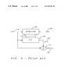
- FIG. 1shows a diagram of a gigabit Ethernet communications system.
- the gigabit Ethernethas two nodes that transmit and receive 1000 M bits per second (bps) full-duplex and bi-directionally.
- Each nodeconsists of four transmitter/receivers (transceivers) 5 a , 5 b , 5 c , 5 d , 15 a , 15 b , 15 c , and 15 d that transmit 250 Mbps each.
- Each transceiver 5 a , . . . , 5 d , 15 a , . . . , 15 dis connected to one end of one of four pair of unshielded twisted-pair cable 10 a , 10 b , 10 c , and 10 d .
- the transmitter 2 of each transceiver 5 a , . . . , 5 d , 15 a , . . . , 15 dforms a five level pulse amplitude modulated (PAM-5) shaped pulse signal that is transferred through the hybrid network 6 to one of the unshielded twisted-pair cable 10 a , . . . , 10 d .
- PAM-5pulse amplitude modulated
- the transmitted signaltraverses the unshielded twisted-pair cable 10 a , . . . , 10 d and is transferred through the hybrid network 6 to the receiver 4 .
- the received signalis sensed, retimed, equalized and transferred to other circuitry for extraction of the digital data.
- the full-duplex bi-directional transmissionconsists of transmitting and receiving data simultaneously in both directions on each of the four wire pairs, minimizing the symbol rate (and thus, the occupied signal bandwidth) on each wire pair by one half, as compared to unidirectional transmission and reception.
- the hybrid network 6is used to enable bi-directional transmission over single wire pairs by filtering out the transmit signal at the receiver.
- the hybrid network 6has good trans-hybrid loss to minimize the amount of transmitter signal that is coupled into the receiver 4 , but it still cannot remove all of the transmitted signal from the adjacent transmitter 2 .
- the residual transmitted signal from the adjacent transmitter 2 from the hybrid 6is defined as the transmit echo signal 25 .
- the crosstalk 20 a , 20 b , and 20 c from transmitters within the same gigabit Ethernet nodeare coupled to the receiver 2 .
- the near-end crosstalk 20 a , 20 b , and 20 c and the transmit echo signal 25must be cancelled from the receive signal to permit recovery of the transmitted signal.
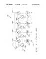
- Each transmitter 4 a , 4 b , 4 c , and 4 dreceives an encoded and scrambled symbol to be transmitted from the side-stream scrambler and symbol encoder 30 , which in turn has received the digital data to be transferred from the Gigabit Media Independent Interface (GMII) 75 .
- the digital transmit filter 35shapes the symbol to be transmitted to condition the transmitted spectrum.
- the digital-to-analog converter 40creates the five level pulse amplitude modulation signal that is then transferred to the hybrid network 6 a for transmission on the unshielded twisted-pair cable 10 a.
- a similar pulse amplitude modulated signalis simultaneously transmitted from a transmitter connected at the opposite end of the unshielded twisted-pair cable 10 a .
- the received signalis separated from the transmitted signal in the hybrid network 6 a and is the input to the analog-to-digital converter 45 .
- the digitized received signalis the feed-forward equalizer (FFE) 50 to compensate for signal distortion introduced in the communication channel.
- the feed-forward equalizer 50combined with a feedback equalizer or decision feedback equalizer 80 often provides better signal equalization than linear equalization when the transmission medium (cable 10 ) introduces strong signal attenuation with specific frequency regions.
- the feed-forward equalizer 50does not modify the noise (echo, crosstalk, etc.).
- the input signals from the side-stream scrambler and symbol encoder 30 to each transmitter 2 b , 2 c , and 2 dare the inputs to the near-end crosstalk cancellers 55 a , 55 b , and 55 c and to the echo canceller 60 .
- the near-end crosstalk cancellers 55 a , 55 b , and 55 c and the echo canceller 60reproduce the near-end echo interference and the near-end crosstalk interference that is present in the received signal.
- the outputs of the near-end crosstalk cancellers 55 a , 55 b , and 55 c and the echo canceller 60are the inputs to the summing circuit 65 .
- the equalized digitized received signalis transferred from the feed-forward equalizer 50 to the summing circuit 65 .
- the summing circuit 65combines the reproduction of the echo interference and the near-end crosstalk interference and the equalized digitized received signal to cancel the echo interference signal and the near-end crosstalk signals induced to the received signal as described above.
- the Viterbi decoder and side-stream descrambler 70provide error correction and resequencing of the receive signal to recover the digital data that is transferred to the Gigabit Media Independent Interface (GMII) 75 for further processing.
- GMIIGigabit Media Independent Interface
- the near-end echo canceller 60 and the crosstalk cancellers 55 a , 55 b , and 55 care known in the art and have been applied to applications such as 100 Base-T Ethernet, asynchronous transfer mode (ATM), local area networks (LAN), and telephone communication networks.
- ATMasynchronous transfer mode
- LANlocal area networks
- telephone communication networkssuch as 100 Base-T Ethernet, asynchronous transfer mode (ATM), local area networks (LAN), and telephone communication networks.
- U.S. Pat. No. 4,995,104(Gitlin) describes a receiver that includes an interference canceller, which receives a corrupted signal and makes an estimate of the desired signal, subtracts the estimated desired signal from a delayed version of the received signal to form an estimate of the interference signal, then forms a final estimate of the desired signal by subtracting the estimated interference from a second delayed version of the received signal.
- U.S. Pat. No. 5,329,586(Agazzi) teaches an echo canceling circuit and associated method for canceling errors encountered in data communications decomposing a lookup-table nonlinear echo canceller into a plurality of smaller lookup tables, and combining outputs of the lookup tables.
- U.S. Pat. No. 5,887,032discusses a method and apparatus for crosstalk cancellation (e.g., NEXT interference) from received signals on a line by adaptively estimating the crosstalk interference from the other lines having interfering transmissions and by canceling the crosstalk interference using the estimated crosstalk interference.
- crosstalk cancellatione.g., NEXT interference
- U.S. Pat. No. 4,669,116discloses an echo cancellation circuit for use with full-duplex data transmission systems.
- the echo cancellercan operate in spite of time invariant non-linearities in the echo channel or in the implementation of the echo canceller itself (such as in D/A converters).
- near-end echocomes from the imperfections of the near-end hybrid network 6 a that separates received signal from the transmitted signal and takes the significant part of the overall signal energy.
- the near-end echo signaldegrades the receiver performance to a great extent and is a large source of error in the received signal. Therefore, the near-end echo canceller 60 is used to reduce the echo signal in the received signal.
- An adaptive echo cancellation techniqueis normally used because of its superior performance. For the receivers like gigabit Ethernet receivers, the performance requirement for the echo canceller is severe, and robustness of the received signal processing is required.
- NTNNear-end crosstalk
- a separate near-end echo/near-end crosstalk cancellation techniqueis necessary.
- the cancellation techniquemust not interact with other circuits in the receiver.
- a correlatormaybe used for the echo cancellation as shown in FIG. 3 .
- a correlator 100obtains the echo signal response for the transmitted symbols X(k) 115 .
- a Finite Impulse Response (FIR) filter 105set with the coefficients C 0 , . . .
- C j 125 obtained by the correlator 100generates the duplicated echo e (k) 135 and subtracts the duplicated echo/NEXT signal e(k) 135 from the received signal X(k) 115 at the receiver.
- the coefficients C 0 , . . . , C j 125 at the FIR 105may be updated once they are set. However, the coefficients C 0 , . . . , C j 125 at the FIR 105 are not usually updated once set because it usually takes thousands of symbols to generate new coefficients C 0 , . . . , C j 125 from the received signal X(k) 115 in the correlator.
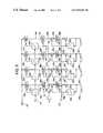
- the multiplier circuit 150 a , 150 b , 150 c , . . . , 150 dreceives the received signal X(k) 115 and the delayed transmitted signals b(k ⁇ j) 165 a , 165 b , 165 c , . . . , 165 d .
- the delayed transmitted signal b(k ⁇ j) 165 a , 165 b , 165 c , . . . , 165 dis the transmitted signal b(k) 120 successively delayed through each of the unit delay elements 150 a , 150 b , 150 c , . . . , 150 d .
- the product of the received signal X(k) 115 and the delayed transmitted signal 165 a , 165 b , 165 c , . . . , 165 dis the output of the multiplier 150 a , 150 b , 150 c , . . . , 150 d and the input of the normalization circuit 160 a , 160 b , 160 c , . . . , 160 d .
- the productis normalized to form the coefficients C 0 , C 1 , C 2 , . . . , C j 125 , by summing a large number of products and dividing the sum of the squares of the delayed transmitted signal b(k ⁇ j).
- An object of this inventionis to provide a communication transmitting and receiving system in which the effects of near-end echo and near-end crosstalk from the communication medium are mitigated.
- Another object of this inventionis to provide an apparatus, which is included in a communication receiving system for adaptively reproducing the near-end echo and near-end crosstalk signal, which are then subtracted from the received signal to mitigate the effects of the near-end echo and near-end crosstalk.
- Another object of this inventionis to adaptively generate filter coefficients for a Finite Impulse Response filter to reproduce the near-end echo and near-end crosstalk.
- an apparatus to cancel echo and crosstalk interference in a receiver of a communication system having simultaneous transmission and receiving on a communication mediumincludes an adaptive correlator and a finite impulse response filter.
- the adaptive correlatoris connected to a receiving circuit to acquire received signals from the communication medium. Further, the adaptive correlator is connected to at least one of a plurality of transmission channels of the communication system to acquire at least one transmitted signal from the adjacent transmission channels.
- the adaptive correlatorgenerates a reproduction of the echo response of the received signals to near-end echo and near-end crosstalk interference from the transmitted signals at an arrival of each received signal.
- the finite impulse filteris connected to the receiving circuit to acquire the received signals, and is connected to the adaptive correlator to receive a plurality of filter coefficients.
- the finite impulse filterreproduces the near-end echo and near-end crosstalk signals from the received signals based on the values of the plurality of filter coefficients.
- the reproduced near-end echo or near-end crosstalk signalsare combined with the received signals to cancel any echo and crosstalk interference from the received signals.
- the filter coefficientsare regenerated in the adaptive correlator at the arrival of each received signal and whereby each new filter coefficient is a weighted sum of a previous coefficient and one received signal multiplied by a time delayed version of one transmitted signal.
- a first embodiment of the adaptive correlatorhas at least one first delaying means connected to one of the transmission channels to delay one of the transmitted signals.
- At least one first multiplying meansis connected to the receiving circuit and one of the first delaying means to multiply the received signal by one delayed transmitted signal to produce a product of the received signals and the one delayed transmitted signal.
- At least one second multiplying meansis connected to one of the first multiplying means to receive the product of the received signals multiplied by the one delayed transmitted signal and multiply this product by a first weighting factor ( ⁇ ⁇ 2 ) to produce a first intermediate coefficient factor.
- the adaptive correlatorhas at least one second delaying means to delay and retain the previous coefficient.
- At least one third multiplying meansis connected to one second delaying means to multiply the previous coefficient by one minus a second weighting factor ( ⁇ ) to produce a second intermediate coefficient factor.
- One of the second multiplying means and one of the third multiplying meansis connected to one of a group of at least one summing means to add the first intermediate coefficient factor and the second intermediate coefficient factor to produce one new filter coefficient.
- the first weighting factoris a quotient of the second weighting factor divided by a variance ( ⁇ 2 ) of the transmitted signal.
- the second weighting factor ⁇is chosen in a manner similar to an equivalent weighting factor used in to what is termed a leaky recursive least squares method to calculate the coefficients of an adaptive filter.
- the received signals and the transmitted signalsare digitized to form binary numbers indicating magnitudes of samples of the received signal and the transmitted signal.
- a second embodiment of the adaptive correlatorhas at least one first delaying means connected to one of the transmission channels to receive and delay on of the digitized samples of the transmitted signal and at least one first shifting means connected to the receiving circuit and one of the first delaying means to shift one of the digitized samples of the received signal according to the binary number of the one digitized sample of the delayed transmitted signal to produce the product of one received signal and the one time delayed transmitted signal.
- the adaptive correlatorhas at least one second shifting means to shift the product of the one received signal and the one time delayed transmitted signal by a first weighting factor ( 1 ⁇ 2 ) to form a weighted product of the one received signal and the one time delayed transmitted signal.
- the adaptive correlatorhas at least one second delaying means to delay and retain the previous coefficient.
- One adder/subtractor means of a group of at least one adder/subtractor meansis connected to one second shifting means and one second delaying means to combine the previous coefficient with the weighted product to form a partially weighted sum.
- One third shifting means of a group of at least one third shifting meansis connected to one adder/subtractor to shift the partially weighted sum by a second weighting factor ( ⁇ ) to form an intermediate weighted sum.
- One adding means of a group of at least one adding meansis connected to one second delaying means and to one third shifting means to additively combine the partially weighted sum and the intermediate weighted sum to generate the new filter coefficient.
- the first weighting factoris the inverse of the variance ( ⁇ 2 ) of the transmitted signal and the second weighting factor ⁇ , as described above, is chosen in a manner similar to an equivalent weighting factor used in to what is termed a leaky recursive least squares method to calculate the coefficients of an adaptive filter.
- FIG. 1is a simplified diagram of the basic structure of a gigabit Ethernet communication link of the prior art.
- FIG. 2is a block diagram of a transceiver of a gigabit Ethernet communication system of the prior art.
- FIG. 3is a block diagram of a near-end echo and near-end crosstalk canceller of the prior art.
- FIG. 4is a schematic diagram of a correlator of the near-end echo and near-end crosstalk canceller of the prior art.
- FIG. 5is a schematic diagram of a first embodiment of a correlator of a near-end echo canceller and a near-end crosstalk canceller of this invention.
- FIG. 6is a schematic diagram of a second embodiment of a correlator of a near-end echo canceller and a near-end crosstalk canceller of this invention.
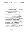
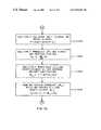
- FIGS. 7 a – 7 care flow diagrams of embodiments of the method to cancel near-end echo/near-end crosstalk from a received signal in a communication system of this invention
- the near-end echo/near-end crosstalk canceller of this inventionhas a correlator 100 of FIG. 3 that creates each coefficient C 0 , . . . , C j 125 of the FIR filter 105 that is the function of the previous coefficient.
- the received signal X(k+1) 115 and the delayed transmitted signals b(k ⁇ j) 240 a , 240 b , 240 c , . . . , 240 dare the inputs to each of the first multipliers 200 a , 200 b , 200 c , . . . , 200 d .
- the delayed transmitted signals b(k ⁇ j)are the outputs of each of the unit delay elements 205 a , 205 b , 205 c , . . . , 205 d .
- the unit delay elements 205 a , 205 b , 205 c , . . . , 205 dsuccessively delay the transmitted signal b(k) 120 to form the delayed transmitted signals b(k ⁇ j) 240 a , 240 b , 240 c , . . . , 240 d.
- the output products 245 a , 245 b , 245 c , . . . , 245 d and the first weighting factor ( ⁇ ⁇ 2 ) 215are inputs to the second multipliers 210 a , 210 b , 210 c , . . . , 210 d .
- the outputs of the second multipliers 210 a , 210 b , 210 c , . . . , 210 dform the weighted products 250 a , 250 b , 250 c , . . . , 250 d.
- Each of the new filter coefficients C 0 (k+1), . . . , Cj(k+1) 225 a , 225 b , 225 c , 225 dis the input to each of the unit delay elements 230 a , 230 b , 230 c , . . . , 230 d to form the previous filter coefficients 255 a , 255 b , 255 c , . . . , 255 d .
- 255 dare the inputs to the third multipliers 235 a , 235 b , 235 c , 235 d .
- the outputs of the third multipliers 235 a , 235 b , 235 c , . . . , 235 dform the weighted previous filter coefficients 260 a , 260 b , 260 c , . . . , 260 d.
- the weighted products 250 a , 250 b , 250 c , . . . , 250 d and the weighted previous filter coefficients 260 a , 260 b , 260 c , . . . , 260 dare respectively the inputs to the summing circuits 220 a , 220 b , 220 c , . . . , 220 d to be additively combined to form the new filter coefficients Cj(k+1) 225 a , 225 b , 225 c , . . . , 225 d .
- the new filter coefficients Cj(k+1) 225 a , 225 b , 225 c , . . . , 225 dare placed at the inputs 125 of the FIR filter 105 of FIG. 3 to set the FIR filter 105 to reproduce the near-end echo/near-end crosstalk for the received signal X(k+1) 115 at a next instant.
- n1 256 ⁇ .004
- the multiplicationcan be performed with shift registers.
- FIG. 6for a discussion of a correlator 100 of a second embodiment of the near-end echo/near-end crosstalk canceller of this invention.
- the digital form of the transmitted symbol b(k)is the input to each of the first unit delay elements 305 a , 305 b , 305 c , . . . , 305 d to form the delayed transmitted symbols 340 a , 340 b , 340 c , . . . , 340 d .
- the sampled digitized received signal 115 and the delayed transmitted signals 340 a , 340 b , 340 c , . . . , 340 dare the inputs to the first shifters 300 a , 300 b , 300 c , . . . , 300 d .
- the first shifters 300 a , 300 b , 300 c , . . . , 300 dshift the sampled digitized received signal 115 according to the values of the delayed transmitted signals 340 a , 340 b , 340 c , . . . , 340 d to form the output products 345 a , 345 b , 345 c , . . . , 345 d.
- the output products 345 a , 345 b , 345 c , . . . , 345 d and a first weighting factor 315are the inputs respectively to the second shifters 310 a , 310 b , 310 c , . . . , 310 d .
- the first weighting factor 315 in this embodimentis the inverse of the variance ( ⁇ 2 ) of transmitted symbols. As described before, for gigabit Ethernet the variance of the transmitted symbols ( ⁇ 2 ) is 2.
- the second shifters 310 a , 310 b , 310 c , . . . , 310 deach shift the output products 345 a , 345 b , 345 c , . . . , 345 d according to the binary value of the first weighting factor ( 1 ⁇ 2 ) to form the weighted products 350 a , 350 b , 350 c , . . . , 350 d.
- the new filter coefficients Cj(k+1) 325 a , 325 b , 325 c , . . . , 325 dare the inputs to the second delay elements 330 a , 330 b , 330 c , . . . , 330 d .
- the new filter coefficients Cj(k+1) 325 a , 325 b , 325 c , . . . , 325 dare delayed and retained for one timing cycle to become the previous filter coefficients 355 a , 355 b , 355 c , . . . , 355 d.
- the weighted products 350 a , 350 b , 350 c , . . . , 350 d and the previous filter coefficients 355 a , 355 b . 355 c , . . . , 355 dare subtractively combined in the arithmetic combining circuits 370 a , 370 b , 370 c , . . . , 370 d to form the preliminary weighted sums 375 a , 375 b , 375 c , . . . , 375 d .
- the summing circuits 320 a , 320 b , 320 c , . . . , 320 dwhere they are additively combined to form the new filter coefficients C 0 (k+1), C 1 (k+1), C 2 (k+1), . . . , Cj(k+1) 225 a , 225 b , 225 c , . . . , 225 d .
- Cj(k+1) 225 a , 225 b , 225 c , . . . , 225 dare the inputs 125 to the FIR filter 105 of FIG. 3 , to set the FIR filter 105 to reproduce the near-end echo/near-end crosstalk for the received signal X(k+1) 115 at the next digitized sample of the received signal X(k+1) 115 .
- the transmit symbols and the received signalsare digital words that respectively are inputs to the digital-to-analog converter 40 of FIG. 2 and outputs from the analog-to-digital converter 45 of FIG. 2 , it is possible to perform the reproduction of the near-end echo/near-end crosstalk as digital words within a computer system such as a digital signal processor.
- a method to cancel near-end echo interference and near-end crosstalk interference that is implemented in a digital signal processoris illustrated in FIGS. 7 a–c.
- a method to cancel echo interference and crosstalk interference present in a received signal from a communication mediumbegins with acquiring 400 the received signal with the echo interference and the crosstalk interference and acquiring 405 the transmitted signals that generate the echo interference and the crosstalk interference.
- the transmitted signalis then delayed 410 to form a delayed transmitted signal.
- the received signalis then correlated with at least one transmitted signal at each cycle of the received signal to generate 415 a new filter coefficient as a weighted sum of a previous filter coefficient and the received signal multiplied by the delayed transmitted signal.
- the received signalis then filtered 420 to reproduce the echo interference and the crosstalk interference.
- the reproduction of the echo interference and the crosstalk interferenceare received combined 425 with the received signal to cancel the echo interference and the crosstalk interference in the received signal.
- a first embodiment of the correlating of the received signalbegins with at least one transmit signal to generate 415 the new filter coefficients begins by multiplying the delayed signal by at least one of the transmitted signals to form a first product.
- the first productis then multiplied 435 by a first weighting factor ( ⁇ ⁇ 2 ) to form a first weighted product.
- the previous filter coefficientare multiplied 440 by a second weighting factor 1 ⁇ to form a second weighted product.
- the first weighted product and the second weighted productare then summed 445 to form the weighted sum.
- the first weighting factoris the quotient of the factor ( ⁇ ) divided by the variance of the transmitted signal ( ⁇ 2 ). As stated above the variance ( ⁇ 2 ) of the transmitted signal for gigabit Ethernet is 2.
- the second weighting factoris one minus the factor ( ⁇ ).
- the weighting factor ⁇is chosen in a manner similar to an equivalent weighting factor used in to what is termed a leaky recursive least squares method to calculate the coefficients of an adaptive filter.
- a second embodiment of the correlating the received signal with at least one transmit signal to generate 415 the new filter coefficientbegins by shifting 450 the received signal according to the delayed transmit signal to form a product of the received signal and the delayed transmit signal.
- the product of the received signal and the delayed transmit signalis further shifted 455 according to a first weighting factor ( 1 ⁇ 2 ) to form a first weighted product.
- the first weighted productis additively combined with the previous filter coefficient to form a first preliminary weighted sum.
- the first preliminary weighted sumis then shifted 470 by a second weighting factor ( ⁇ ) to form a second weighted product.
- the second weighted product and the previous filter coefficientare then additively combined 475 to generate the new filter coefficient.
- the first weighting factoris the inverse of the variance ( ⁇ 2 ) of the transmitted signal and the second weighting factor is the factor ⁇ .
- the second weighting factor ⁇is chosen, as above described, in a manner similar to an equivalent weighting factor used in to what is termed a leaky recursive least squares method to calculate the coefficients of an adaptive filter.
Landscapes
- Engineering & Computer Science (AREA)
- Computer Networks & Wireless Communication (AREA)
- Signal Processing (AREA)
- Cable Transmission Systems, Equalization Of Radio And Reduction Of Echo (AREA)
Abstract
Description
- “Gigabit Ethernet Over 4-
Pair 100 OHM Category 5 Cabling,” Gigabit Ethernet Alliance, Cupertino, Calif., 1999, - “Gigabit Ethernet 1000 Base-T,” 1000 BASE-T Tutorial Series, Interoperability Laboratory Gigabit Ethernet Consortium, University of New Hampshire, Durham, N.H., 1998,
- “Design Considerations for Gigabit Ethernet 1000 Base-T Twisted-pair Transceivers,” Hatamian et al., Proceedings of the IEEE 1999 Custom Integrated Circuit Conference, IEEE, 1998, pp. 335–342.
- “Gigabit Ethernet Over 4-
CJ(k)=N(x(k)*b(k−j))
- where:
- Cjis the value of each
coefficient 125 of theFIR filter 105. - N is a normalizing factor for the
coefficients 125. - X(k) is the magnitude of the received
signal 115. - b(k−j) is the magnitude of the delayed transmitted
signal 120.
- Cjis the value of each
- where:
- where;
- n is the number of symbols used to determine the coefficient Cj.
- where;
to produce a first intermediate coefficient factor.
to form a weighted product of the one received signal and the one time delayed transmitted signal.
- where.
- Cj(k) is the filter coefficient from the previous time period.
- Cj(k+1) is the filter coefficient for the FIR filter for the current time period.
- X(k+1) is the signal received during the current time period.
- b(k−j) is the transmitted signal delayed by j delay units.
- σ2is the variance of the transmitted symbol. For gigabit Ethernet σ2=2.
- β is a weighting factor.
The weighting factor β is chosen in a manner similar to an equivalent weighting factor used in to what is termed a leaky recursive least squares method to calculate the coefficients of an adaptive filter. For this embodiment of this invention, a number of the symbols n (for instance, n=256 symbols) is chosen and the weighting factor β is equal to the inverse of the number of the symbols. That is:
- where.
215 are inputs to the
As described above, the weighting factor β is chosen in a manner similar to an equivalent weighting factor used in to what is termed a leaky recursive least squares method to calculate the coefficients of an adaptive filter. For this embodiment of this invention a number of the symbols n (for instance, n=256 symbols) is chosen and the weighting factor β is equal to the inverse of the number of the symbols. That is:
to form the
to form a first weighted product.
to form a first weighted product. The first weighted product is additively combined with the previous filter coefficient to form a first preliminary weighted sum.
Claims (84)
Priority Applications (2)
| Application Number | Priority Date | Filing Date | Title |
|---|---|---|---|
| US09/465,228US6934387B1 (en) | 1999-12-17 | 1999-12-17 | Method and apparatus for digital near-end echo/near-end crosstalk cancellation with adaptive correlation |
| US11/149,220US7826609B1 (en) | 1999-12-17 | 2005-06-10 | Method and apparatus for digital near-end echo/near-end crosstalk cancellation with adaptive correlation |
Applications Claiming Priority (1)
| Application Number | Priority Date | Filing Date | Title |
|---|---|---|---|
| US09/465,228US6934387B1 (en) | 1999-12-17 | 1999-12-17 | Method and apparatus for digital near-end echo/near-end crosstalk cancellation with adaptive correlation |
Related Child Applications (1)
| Application Number | Title | Priority Date | Filing Date |
|---|---|---|---|
| US11/149,220ContinuationUS7826609B1 (en) | 1999-12-17 | 2005-06-10 | Method and apparatus for digital near-end echo/near-end crosstalk cancellation with adaptive correlation |
Publications (1)
| Publication Number | Publication Date |
|---|---|
| US6934387B1true US6934387B1 (en) | 2005-08-23 |
Family
ID=34837315
Family Applications (2)
| Application Number | Title | Priority Date | Filing Date |
|---|---|---|---|
| US09/465,228Expired - LifetimeUS6934387B1 (en) | 1999-12-17 | 1999-12-17 | Method and apparatus for digital near-end echo/near-end crosstalk cancellation with adaptive correlation |
| US11/149,220Expired - Fee RelatedUS7826609B1 (en) | 1999-12-17 | 2005-06-10 | Method and apparatus for digital near-end echo/near-end crosstalk cancellation with adaptive correlation |
Family Applications After (1)
| Application Number | Title | Priority Date | Filing Date |
|---|---|---|---|
| US11/149,220Expired - Fee RelatedUS7826609B1 (en) | 1999-12-17 | 2005-06-10 | Method and apparatus for digital near-end echo/near-end crosstalk cancellation with adaptive correlation |
Country Status (1)
| Country | Link |
|---|---|
| US (2) | US6934387B1 (en) |
Cited By (32)
| Publication number | Priority date | Publication date | Assignee | Title |
|---|---|---|---|---|
| US20020122503A1 (en)* | 2001-03-01 | 2002-09-05 | Agazzi Oscar E. | Digital signal processing based de-serializer |
| US20040146002A1 (en)* | 2003-01-28 | 2004-07-29 | Kameran Azadet | Method and apparatus for reducing cross-talk with reduced redundancies |
| US20050074055A1 (en)* | 2003-10-06 | 2005-04-07 | Hiroshi Takatori | System, method and apparatus for crosstalk cancellation |
| US20060067396A1 (en)* | 2004-09-27 | 2006-03-30 | Benny Christensen | Feed forward equalizer for a communication system |
| US20060067542A1 (en)* | 2004-09-27 | 2006-03-30 | Benny Christensen | Feed forward equalizer |
| US20070133786A1 (en)* | 2005-12-09 | 2007-06-14 | Mitel Networks Corporation | System for conditioning echo response of loop start trunk line |
| US20070133815A1 (en)* | 2005-12-10 | 2007-06-14 | Min-Ho Cheong | Apparatus and method for cancellation of partially overlapped crosstalk signals |
| US20070201393A1 (en)* | 2006-02-27 | 2007-08-30 | Devabhaktuni Srikrishna | Regulation of transmission power within a wireless network |
| US20070211794A1 (en)* | 2006-03-13 | 2007-09-13 | Teranetics, Inc. | Tranceiver non-linearity cancellation |
| WO2008032994A1 (en)* | 2006-09-14 | 2008-03-20 | Solid Technologies Inc. | System and method for cancelling echo |
| US20080233903A1 (en)* | 2007-03-19 | 2008-09-25 | Teranetics, Inc. | Selection of filter coefficients for tranceiver non-linearity signal cancellation |
| US20080267327A1 (en)* | 2002-07-03 | 2008-10-30 | Xiaopeng Chen | Nonlinear echo compensator for class B transmitter line driver |
| US20090238102A1 (en)* | 2008-03-20 | 2009-09-24 | Teranetics, Inc. | Generating an estimated non-linear echo signal |
| WO2009126187A1 (en)* | 2008-04-09 | 2009-10-15 | Conexant Systems, Inc. | Cooperative mimo for alien noise cancellation (comac) for upstream vdsl systems |
| US20090323566A1 (en)* | 2008-06-25 | 2009-12-31 | Realtek Semiconductor Corp. | All-digital timing control for multi-channel full-duplex transceiver |
| US7729679B1 (en) | 2006-06-09 | 2010-06-01 | Marvell International Ltd. | Dynamic bandwidth filter for an FM receiver |
| US20100238785A1 (en)* | 2005-04-12 | 2010-09-23 | NewWire System, Inc., a California corporation | Cancellation of Crosstalk Energy in Communication Loops |
| US7826609B1 (en)* | 1999-12-17 | 2010-11-02 | Marvell International Ltd. | Method and apparatus for digital near-end echo/near-end crosstalk cancellation with adaptive correlation |
| CN101163178B (en)* | 2007-11-01 | 2011-05-11 | 中兴通讯股份有限公司 | Echo counteracting method and system in wireless communication system |
| US8295214B2 (en) | 2010-04-22 | 2012-10-23 | Plx Technology, Inc. | Reducing transmit signal components of a receive signal of a transceiver |
| US8296347B2 (en) | 2007-02-07 | 2012-10-23 | Vintomie Networks B.V., Llc | Use of line characterization to configure physical layered devices |
| US8737188B1 (en) | 2012-01-11 | 2014-05-27 | Audience, Inc. | Crosstalk cancellation systems and methods |
| US9437180B2 (en) | 2010-01-26 | 2016-09-06 | Knowles Electronics, Llc | Adaptive noise reduction using level cues |
| US9502048B2 (en) | 2010-04-19 | 2016-11-22 | Knowles Electronics, Llc | Adaptively reducing noise to limit speech distortion |
| US9536540B2 (en) | 2013-07-19 | 2017-01-03 | Knowles Electronics, Llc | Speech signal separation and synthesis based on auditory scene analysis and speech modeling |
| US9640194B1 (en) | 2012-10-04 | 2017-05-02 | Knowles Electronics, Llc | Noise suppression for speech processing based on machine-learning mask estimation |
| US9799330B2 (en) | 2014-08-28 | 2017-10-24 | Knowles Electronics, Llc | Multi-sourced noise suppression |
| WO2017190252A1 (en) | 2016-05-06 | 2017-11-09 | Genesis Technical Systems Corp. | Near-end crosstalk cancellation |
| US9830899B1 (en) | 2006-05-25 | 2017-11-28 | Knowles Electronics, Llc | Adaptive noise cancellation |
| US10542154B2 (en)* | 2015-10-16 | 2020-01-21 | Panasonic Intellectual Property Management Co., Ltd. | Device for assisting two-way conversation and method for assisting two-way conversation |
| US10819389B2 (en)* | 2018-06-29 | 2020-10-27 | Toyota Jidosha Kabushiki Kaisha | Reducing adjacent channel interference for wireless vehicular messages |
| US20210399764A1 (en)* | 2021-09-01 | 2021-12-23 | Intel Corporation | Near-end crosstalk cancellation system |
Families Citing this family (6)
| Publication number | Priority date | Publication date | Assignee | Title |
|---|---|---|---|---|
| US9232072B2 (en) | 2013-03-13 | 2016-01-05 | Google Inc. | Participant controlled spatial AEC |
| WO2015123815A1 (en)* | 2014-02-19 | 2015-08-27 | 华为技术有限公司 | Signal processing method, apparatus and system |
| WO2016101241A1 (en)* | 2014-12-26 | 2016-06-30 | 华为技术有限公司 | Signal acquiring method, device and system |
| CN107333017B (en)* | 2017-05-22 | 2019-08-20 | 西南交通大学 | An Adaptive Echo Cancellation Method Using Reuse Weight Exponential Error |
| TWI739317B (en)* | 2020-02-24 | 2021-09-11 | 瑞昱半導體股份有限公司 | Receiver and channel estimation method |
| CN116982285A (en) | 2021-01-29 | 2023-10-31 | 马维尔亚洲私人有限公司 | Method and apparatus for training a full duplex communication link |
Citations (24)
| Publication number | Priority date | Publication date | Assignee | Title |
|---|---|---|---|---|
| US4561067A (en)* | 1982-06-23 | 1985-12-24 | British Telecommunications | Multi-channel cross-talk interference reduction circuit using modulation-multiplying-demodulation correlator |
| US4571720A (en)* | 1983-02-25 | 1986-02-18 | Telecommunications Radioelectriques Et Telephoniques T.R.T. | Method and apparatus for reducing the convergence time of an echo canceller |
| US4669116A (en) | 1982-12-09 | 1987-05-26 | Regents Of The University Of California | Non-linear echo cancellation of data signals |
| US4807173A (en)* | 1986-06-20 | 1989-02-21 | U.S. Philips Corporation | Frequency-domain block-adaptive digital filter |
| US4852081A (en)* | 1983-05-26 | 1989-07-25 | Centre National De La Recherche Scientifique | Echo suppressor with adaptive digital filter for transmission system |
| US4995104A (en) | 1989-05-08 | 1991-02-19 | At&T Bell Laboratories | Interference cancelling circuit and method |
| US5062102A (en)* | 1988-12-01 | 1991-10-29 | Nec Corporation | Echo canceller with means for determining filter coefficients from autocorrelation and cross-correlation coefficients |
| US5181198A (en)* | 1991-03-12 | 1993-01-19 | Bell Communications Research, Inc. | Coordinated transmission for two-pair digital subscriber lines |
| US5329586A (en) | 1992-05-29 | 1994-07-12 | At&T Bell Laboratories | Nonlinear echo canceller for data signals using a non-redundant distributed lookup-table architecture |
| US5396554A (en)* | 1991-03-14 | 1995-03-07 | Nec Corporation | Multi-channel echo canceling method and apparatus |
| US5473686A (en)* | 1994-02-01 | 1995-12-05 | Tandy Corporation | Echo cancellation apparatus |
| US5577116A (en)* | 1994-09-16 | 1996-11-19 | North Carolina State University | Apparatus and method for echo characterization of a communication channel |
| US5887032A (en) | 1996-09-03 | 1999-03-23 | Amati Communications Corp. | Method and apparatus for crosstalk cancellation |
| WO1999046867A1 (en) | 1998-03-09 | 1999-09-16 | Broadcom Corporation | Gigabit ethernet transceiver |
| WO2000027079A1 (en) | 1998-10-30 | 2000-05-11 | Broadcom Corporation | Internet gigabit ethernet transmitter architecture |
| WO2000028691A2 (en) | 1998-11-09 | 2000-05-18 | Broadcom Corporation, Et Al. | Multi-pair gigabit ethernet transceiver |
| WO2000028663A2 (en) | 1998-11-09 | 2000-05-18 | Broadcom Corporation | Fir filter structure with low latency for gigabit ethernet applications |
| WO2000028712A2 (en) | 1998-10-30 | 2000-05-18 | Broadcom Corporation | Cable modem system |
| WO2000028668A1 (en) | 1998-11-09 | 2000-05-18 | Broadcom Corporation | Forward error corrector |
| WO2000035094A1 (en) | 1998-12-07 | 2000-06-15 | Broadcom Corporation | Low jitter high phase resolution pll-based timing recovery system |
| US6078567A (en)* | 1994-11-10 | 2000-06-20 | British Telecommunications Plc | Echo cancellation using cross-correlation of buffered receive and transmit sample segments to determine cancelling filter coefficients |
| US6442274B1 (en)* | 1998-12-28 | 2002-08-27 | Nec Corporation | Method and apparatus of canceling echoes in multi-channel |
| US6570985B1 (en)* | 1998-01-09 | 2003-05-27 | Ericsson Inc. | Echo canceler adaptive filter optimization |
| US6584159B1 (en)* | 1998-11-09 | 2003-06-24 | Agere Systems Inc. | Mixed-mode next/echo canceller for pulse amplitude modulated (PAM) signals |
Family Cites Families (4)
| Publication number | Priority date | Publication date | Assignee | Title |
|---|---|---|---|---|
| US6078645A (en)* | 1997-02-20 | 2000-06-20 | Lucent Technologies Inc. | Apparatus and method for monitoring full duplex data communications |
| US6373908B2 (en)* | 1998-11-11 | 2002-04-16 | Broadcom Corporation | Adaptive electronic transmission signal cancellation apparatus for full duplex communication |
| US6934387B1 (en)* | 1999-12-17 | 2005-08-23 | Marvell International Ltd. | Method and apparatus for digital near-end echo/near-end crosstalk cancellation with adaptive correlation |
| US6741707B2 (en)* | 2001-06-22 | 2004-05-25 | Trustees Of Dartmouth College | Method for tuning an adaptive leaky LMS filter |
- 1999
- 1999-12-17USUS09/465,228patent/US6934387B1/ennot_activeExpired - Lifetime
- 2005
- 2005-06-10USUS11/149,220patent/US7826609B1/ennot_activeExpired - Fee Related
Patent Citations (25)
| Publication number | Priority date | Publication date | Assignee | Title |
|---|---|---|---|---|
| US4561067A (en)* | 1982-06-23 | 1985-12-24 | British Telecommunications | Multi-channel cross-talk interference reduction circuit using modulation-multiplying-demodulation correlator |
| US4669116A (en) | 1982-12-09 | 1987-05-26 | Regents Of The University Of California | Non-linear echo cancellation of data signals |
| US4571720A (en)* | 1983-02-25 | 1986-02-18 | Telecommunications Radioelectriques Et Telephoniques T.R.T. | Method and apparatus for reducing the convergence time of an echo canceller |
| US4852081A (en)* | 1983-05-26 | 1989-07-25 | Centre National De La Recherche Scientifique | Echo suppressor with adaptive digital filter for transmission system |
| US4807173A (en)* | 1986-06-20 | 1989-02-21 | U.S. Philips Corporation | Frequency-domain block-adaptive digital filter |
| US5062102A (en)* | 1988-12-01 | 1991-10-29 | Nec Corporation | Echo canceller with means for determining filter coefficients from autocorrelation and cross-correlation coefficients |
| US4995104A (en) | 1989-05-08 | 1991-02-19 | At&T Bell Laboratories | Interference cancelling circuit and method |
| US5181198A (en)* | 1991-03-12 | 1993-01-19 | Bell Communications Research, Inc. | Coordinated transmission for two-pair digital subscriber lines |
| US5396554A (en)* | 1991-03-14 | 1995-03-07 | Nec Corporation | Multi-channel echo canceling method and apparatus |
| US5329586A (en) | 1992-05-29 | 1994-07-12 | At&T Bell Laboratories | Nonlinear echo canceller for data signals using a non-redundant distributed lookup-table architecture |
| US5473686A (en)* | 1994-02-01 | 1995-12-05 | Tandy Corporation | Echo cancellation apparatus |
| US5577116A (en)* | 1994-09-16 | 1996-11-19 | North Carolina State University | Apparatus and method for echo characterization of a communication channel |
| US6078567A (en)* | 1994-11-10 | 2000-06-20 | British Telecommunications Plc | Echo cancellation using cross-correlation of buffered receive and transmit sample segments to determine cancelling filter coefficients |
| US5887032A (en) | 1996-09-03 | 1999-03-23 | Amati Communications Corp. | Method and apparatus for crosstalk cancellation |
| US6570985B1 (en)* | 1998-01-09 | 2003-05-27 | Ericsson Inc. | Echo canceler adaptive filter optimization |
| WO1999046867A1 (en) | 1998-03-09 | 1999-09-16 | Broadcom Corporation | Gigabit ethernet transceiver |
| WO2000027079A1 (en) | 1998-10-30 | 2000-05-11 | Broadcom Corporation | Internet gigabit ethernet transmitter architecture |
| WO2000028712A2 (en) | 1998-10-30 | 2000-05-18 | Broadcom Corporation | Cable modem system |
| WO2000028691A2 (en) | 1998-11-09 | 2000-05-18 | Broadcom Corporation, Et Al. | Multi-pair gigabit ethernet transceiver |
| WO2000028663A2 (en) | 1998-11-09 | 2000-05-18 | Broadcom Corporation | Fir filter structure with low latency for gigabit ethernet applications |
| WO2000028668A1 (en) | 1998-11-09 | 2000-05-18 | Broadcom Corporation | Forward error corrector |
| US6272173B1 (en)* | 1998-11-09 | 2001-08-07 | Broadcom Corporation | Efficient fir filter for high-speed communication |
| US6584159B1 (en)* | 1998-11-09 | 2003-06-24 | Agere Systems Inc. | Mixed-mode next/echo canceller for pulse amplitude modulated (PAM) signals |
| WO2000035094A1 (en) | 1998-12-07 | 2000-06-15 | Broadcom Corporation | Low jitter high phase resolution pll-based timing recovery system |
| US6442274B1 (en)* | 1998-12-28 | 2002-08-27 | Nec Corporation | Method and apparatus of canceling echoes in multi-channel |
Non-Patent Citations (6)
| Title |
|---|
| "Design Considerations for Gigabit Ethernet 1000 Base-T Twisted-pair Transceivers", Hatamian et al., Proceedings of the IEEE 1999 Custom Integrated Circuit Conference, IEEE, 1998, pp. 335-342. |
| "Gigabit Ethernet 1000 Base-T", 1000 Base-T Tutorial Series, Interoperability Laboratory Gigabit Ethernet Consortium, University of New Hampshire, Durham, NH, 1998. |
| "Gigabit Ethernet Over 4-Pair 100 OHM Category 5 Cabling", Gigabit Ethernet Alliance, Cupertino, CA, 1999. |
| Cherubini et al., "100 Base-T2: 100Mbit/s Ethernet Over Two Pairs of Category-3 Cabling", 1997 IEEE Int'l Conf. on Communications, pp. 1014-1018, vol. 2. |
| Im et al., "A Piplined Adaptive Next Canceller", IEEE Transactions on Signal Processing, pp. 2252-2258, Aug. 1998, vol. 46, Issue: 8 ISSN: 1053-587x. |
| Sen M. Kuo and Dennis R. Morgan, Active Noise Control Systems: Algorithms and DSP Implementations, John Wiley & Sons, Inc., 1996, pp 35-38, 77-78, and 170. |
Cited By (61)
| Publication number | Priority date | Publication date | Assignee | Title |
|---|---|---|---|---|
| US7826609B1 (en)* | 1999-12-17 | 2010-11-02 | Marvell International Ltd. | Method and apparatus for digital near-end echo/near-end crosstalk cancellation with adaptive correlation |
| US7336729B2 (en)* | 2001-03-01 | 2008-02-26 | Broadcom Corporation | Digital signal processing based de-serializer |
| US20020122503A1 (en)* | 2001-03-01 | 2002-09-05 | Agazzi Oscar E. | Digital signal processing based de-serializer |
| US8989251B2 (en)* | 2002-07-03 | 2015-03-24 | Marvell International Ltd. | Method and apparatus to compensate for nonlinear echo in an output of a current source |
| US8743939B2 (en) | 2002-07-03 | 2014-06-03 | Marvell International Ltd. | Nonlinear echo compensator for class B transmitter line driver |
| US20140269247A1 (en)* | 2002-07-03 | 2014-09-18 | Marvell International Ltd. | Method and apparatus to compensate for nonlinear echo in an output of a current source |
| US20080267327A1 (en)* | 2002-07-03 | 2008-10-30 | Xiaopeng Chen | Nonlinear echo compensator for class B transmitter line driver |
| US20040146002A1 (en)* | 2003-01-28 | 2004-07-29 | Kameran Azadet | Method and apparatus for reducing cross-talk with reduced redundancies |
| US7548599B2 (en)* | 2003-01-28 | 2009-06-16 | Agere Systems Inc. | Method and apparatus for reducing cross-talk with reduced redundancies |
| US20090290622A1 (en)* | 2003-10-06 | 2009-11-26 | Hiroshi Takatori | System, method and apparatus for crosstalk cancellation |
| US7570685B2 (en)* | 2003-10-06 | 2009-08-04 | Hiroshi Takatori | System, method and apparatus for crosstalk cancellation |
| WO2005036761A3 (en)* | 2003-10-06 | 2006-10-12 | Keyeye | System, method and apparatus for crosstalk cancellation |
| US20050074055A1 (en)* | 2003-10-06 | 2005-04-07 | Hiroshi Takatori | System, method and apparatus for crosstalk cancellation |
| US8787488B2 (en) | 2003-10-06 | 2014-07-22 | Vintomie Networks B.V., Llc | System, method and apparatus for crosstalk cancellation |
| US20060067542A1 (en)* | 2004-09-27 | 2006-03-30 | Benny Christensen | Feed forward equalizer |
| US20060067396A1 (en)* | 2004-09-27 | 2006-03-30 | Benny Christensen | Feed forward equalizer for a communication system |
| US7738546B2 (en) | 2004-09-27 | 2010-06-15 | Intel Corporation | Feed forward equalizer for a communication system |
| US7551667B2 (en)* | 2004-09-27 | 2009-06-23 | Intel Corporation | Feed forward equalizer |
| US8509050B2 (en)* | 2005-04-12 | 2013-08-13 | Newwire Systems, Inc. | Cancellation of crosstalk energy in communication loops |
| US20100238785A1 (en)* | 2005-04-12 | 2010-09-23 | NewWire System, Inc., a California corporation | Cancellation of Crosstalk Energy in Communication Loops |
| US20070133786A1 (en)* | 2005-12-09 | 2007-06-14 | Mitel Networks Corporation | System for conditioning echo response of loop start trunk line |
| US8654967B2 (en) | 2005-12-09 | 2014-02-18 | Mitel Networks Corporation | System for conditioning echo response of loop start trunk line |
| US7640000B2 (en) | 2005-12-10 | 2009-12-29 | Electronics And Telecommunications Research Institute | Apparatus and method for cancellation of partially overlapped crosstalk signals |
| US20070133815A1 (en)* | 2005-12-10 | 2007-06-14 | Min-Ho Cheong | Apparatus and method for cancellation of partially overlapped crosstalk signals |
| US20070201393A1 (en)* | 2006-02-27 | 2007-08-30 | Devabhaktuni Srikrishna | Regulation of transmission power within a wireless network |
| US7720499B2 (en) | 2006-02-27 | 2010-05-18 | Tropos Networks, Inc. | Regulation of transmission power control in mitigate self interference by optimizing link transmission parameters in a wireless network |
| US8279912B2 (en) | 2006-03-13 | 2012-10-02 | Plx Technology, Inc. | Tranceiver non-linearity cancellation |
| US20070211794A1 (en)* | 2006-03-13 | 2007-09-13 | Teranetics, Inc. | Tranceiver non-linearity cancellation |
| US9830899B1 (en) | 2006-05-25 | 2017-11-28 | Knowles Electronics, Llc | Adaptive noise cancellation |
| US7729679B1 (en) | 2006-06-09 | 2010-06-01 | Marvell International Ltd. | Dynamic bandwidth filter for an FM receiver |
| US20080205661A1 (en)* | 2006-09-14 | 2008-08-28 | Solid Technologies Inc. | System and method for cancelling echo |
| US8155303B2 (en) | 2006-09-14 | 2012-04-10 | Solid Technologies, Inc. | System and method for cancelling echo |
| WO2008032994A1 (en)* | 2006-09-14 | 2008-03-20 | Solid Technologies Inc. | System and method for cancelling echo |
| US8959132B2 (en) | 2007-02-07 | 2015-02-17 | Vintomie Networks B.V., Llc | Use of line characterization to configure physical layered devices |
| US8296347B2 (en) | 2007-02-07 | 2012-10-23 | Vintomie Networks B.V., Llc | Use of line characterization to configure physical layered devices |
| US7957456B2 (en) | 2007-03-19 | 2011-06-07 | Plx Technology, Inc. | Selection of filter coefficients for tranceiver non-linearity signal cancellation |
| US20080233903A1 (en)* | 2007-03-19 | 2008-09-25 | Teranetics, Inc. | Selection of filter coefficients for tranceiver non-linearity signal cancellation |
| CN101163178B (en)* | 2007-11-01 | 2011-05-11 | 中兴通讯股份有限公司 | Echo counteracting method and system in wireless communication system |
| US8416719B2 (en) | 2008-03-20 | 2013-04-09 | Aquantia Corporation | Generating an estimated non-linear echo signal |
| US20090238102A1 (en)* | 2008-03-20 | 2009-09-24 | Teranetics, Inc. | Generating an estimated non-linear echo signal |
| WO2009126187A1 (en)* | 2008-04-09 | 2009-10-15 | Conexant Systems, Inc. | Cooperative mimo for alien noise cancellation (comac) for upstream vdsl systems |
| US8248974B2 (en) | 2008-06-25 | 2012-08-21 | Realtek Semiconductor Corp. | All-digital timing control for multi-channel full-duplex transceiver |
| US20090323566A1 (en)* | 2008-06-25 | 2009-12-31 | Realtek Semiconductor Corp. | All-digital timing control for multi-channel full-duplex transceiver |
| US9437180B2 (en) | 2010-01-26 | 2016-09-06 | Knowles Electronics, Llc | Adaptive noise reduction using level cues |
| US9502048B2 (en) | 2010-04-19 | 2016-11-22 | Knowles Electronics, Llc | Adaptively reducing noise to limit speech distortion |
| US8295214B2 (en) | 2010-04-22 | 2012-10-23 | Plx Technology, Inc. | Reducing transmit signal components of a receive signal of a transceiver |
| US8737188B1 (en) | 2012-01-11 | 2014-05-27 | Audience, Inc. | Crosstalk cancellation systems and methods |
| US9049282B1 (en)* | 2012-01-11 | 2015-06-02 | Audience, Inc. | Cross-talk cancellation |
| US9640194B1 (en) | 2012-10-04 | 2017-05-02 | Knowles Electronics, Llc | Noise suppression for speech processing based on machine-learning mask estimation |
| US9536540B2 (en) | 2013-07-19 | 2017-01-03 | Knowles Electronics, Llc | Speech signal separation and synthesis based on auditory scene analysis and speech modeling |
| US9799330B2 (en) | 2014-08-28 | 2017-10-24 | Knowles Electronics, Llc | Multi-sourced noise suppression |
| US10542154B2 (en)* | 2015-10-16 | 2020-01-21 | Panasonic Intellectual Property Management Co., Ltd. | Device for assisting two-way conversation and method for assisting two-way conversation |
| WO2017190252A1 (en) | 2016-05-06 | 2017-11-09 | Genesis Technical Systems Corp. | Near-end crosstalk cancellation |
| CN109196785A (en)* | 2016-05-06 | 2019-01-11 | 创世纪技术系统公司 | Near-end cross is eliminated |
| US20190123781A1 (en)* | 2016-05-06 | 2019-04-25 | Genesis Technical Systems Corp. | Near-end crosstalk cancellation |
| EP3453116A4 (en)* | 2016-05-06 | 2019-11-20 | Genesis Technical Systems Corp. | Near-end crosstalk cancellation |
| US10581485B2 (en)* | 2016-05-06 | 2020-03-03 | Genesis Technical Systems Corp. | Near-end crosstalk cancellation |
| US11025298B2 (en) | 2016-05-06 | 2021-06-01 | Genesis Technical Systems Corp. | Near-end crosstalk cancellation |
| US10819389B2 (en)* | 2018-06-29 | 2020-10-27 | Toyota Jidosha Kabushiki Kaisha | Reducing adjacent channel interference for wireless vehicular messages |
| US20210399764A1 (en)* | 2021-09-01 | 2021-12-23 | Intel Corporation | Near-end crosstalk cancellation system |
| US12413261B2 (en)* | 2021-09-01 | 2025-09-09 | Intel Corporation | Near-end crosstalk cancellation system |
Also Published As
| Publication number | Publication date |
|---|---|
| US7826609B1 (en) | 2010-11-02 |
Similar Documents
| Publication | Publication Date | Title |
|---|---|---|
| US6934387B1 (en) | Method and apparatus for digital near-end echo/near-end crosstalk cancellation with adaptive correlation | |
| US5396517A (en) | Transversal filter useable in echo canceler, decision feedback equalizer applications for minimizing non-linear distortion in signals conveyed over full duplex two-wire communication link | |
| US4535206A (en) | Echo cancellation in two-wire full-duplex data transmission with estimation of far-end data components | |
| US8787488B2 (en) | System, method and apparatus for crosstalk cancellation | |
| US7623578B2 (en) | Time domain equalization using frequency domain operations | |
| US7362791B2 (en) | Method and apparatus for domain transformation multiple signal processing | |
| US9461703B1 (en) | Interference signal compensation | |
| US5319585A (en) | High resolution filtering using low resolution processors | |
| US6912208B2 (en) | Method and apparatus for equalization and crosstalk mitigation | |
| US7068780B1 (en) | Hybrid echo canceller | |
| US6430287B1 (en) | Combined parallel adaptive equalizer/echo canceller | |
| CA1175521A (en) | Echo cancellation in two-wire full-duplex data transmission with estimation of far-end data components | |
| US6859508B1 (en) | Four dimensional equalizer and far-end cross talk canceler in Gigabit Ethernet signals | |
| EP2503704B1 (en) | Method and apparatus for equalization and crosstalk mitigation | |
| US8126078B2 (en) | Method and apparatus for reducing noise in an unbalanced channel using common mode component | |
| US7548599B2 (en) | Method and apparatus for reducing cross-talk with reduced redundancies | |
| US6741701B1 (en) | Dual echo canceller and method for increasing dynamic range of a receiver | |
| EP3190757A1 (en) | Multi-tones narrow band rf noise elimination through adaptive algorithm | |
| US6826279B1 (en) | Base band echo cancellation using laguerre echo estimation | |
| US6687288B1 (en) | NEXT cancellation for modem pools | |
| Koike | Convergence analysis of a data echo canceller with a stochastic gradient adaptive FIR filter using the sign algorithm | |
| US7366231B2 (en) | Sub-block domain transformation multiple signal processing | |
| US20030128781A1 (en) | Means and method for precursor ISI cancellation | |
| US20030215086A1 (en) | Methods and systems for providing multi-path echo cancellation | |
| JPH03145826A (en) | Echo cancelling system and echo canceler |
Legal Events
| Date | Code | Title | Description |
|---|---|---|---|
| AS | Assignment | Owner name:MARVELL SEMICONDUCTOR, INC., CALIFORNIA Free format text:ASSIGNMENT OF ASSIGNORS INTEREST;ASSIGNOR:KIM, BEOMSUP;REEL/FRAME:010474/0065 Effective date:19991208 | |
| AS | Assignment | Owner name:MARVELL INTERNATIONAL LTD., BERMUDA Free format text:ASSIGNMENT OF ASSIGNORS INTEREST;ASSIGNOR:MARVELL TECHNOLOGY GROUP, LTD.;REEL/FRAME:011560/0916 Effective date:20010119 | |
| STCF | Information on status: patent grant | Free format text:PATENTED CASE | |
| REFU | Refund | Free format text:REFUND - PAYMENT OF MAINTENANCE FEE, 4TH YEAR, LARGE ENTITY (ORIGINAL EVENT CODE: R1551); ENTITY STATUS OF PATENT OWNER: LARGE ENTITY Free format text:REFUND - SURCHARGE FOR LATE PAYMENT, LARGE ENTITY (ORIGINAL EVENT CODE: R1554); ENTITY STATUS OF PATENT OWNER: LARGE ENTITY | |
| FPAY | Fee payment | Year of fee payment:4 | |
| FPAY | Fee payment | Year of fee payment:8 | |
| FPAY | Fee payment | Year of fee payment:12 | |
| AS | Assignment | Owner name:MARVELL TECHNOLOGY GROUP, LTD., BERMUDA Free format text:CORRECTIVE ASSIGNMENT TO CORRECT THE RECEIVING PARTY NAME PREVIOUSLY RECORDED AT REEL: 10474 FRAME: 065. ASSIGNOR(S) HEREBY CONFIRMS THE ASSIGNMENT;ASSIGNOR:KIM, BEOMSUP;REEL/FRAME:051252/0881 Effective date:19991208 | |
| AS | Assignment | Owner name:CAVIUM INTERNATIONAL, CAYMAN ISLANDS Free format text:ASSIGNMENT OF ASSIGNORS INTEREST;ASSIGNOR:MARVELL INTERNATIONAL LTD.;REEL/FRAME:052918/0001 Effective date:20191231 | |
| AS | Assignment | Owner name:MARVELL ASIA PTE, LTD., SINGAPORE Free format text:ASSIGNMENT OF ASSIGNORS INTEREST;ASSIGNOR:CAVIUM INTERNATIONAL;REEL/FRAME:053475/0001 Effective date:20191231 |