US6933442B2 - Methods and apparatus to secure a ground strap assembly to an electrically conductive member - Google Patents
Methods and apparatus to secure a ground strap assembly to an electrically conductive memberDownload PDFInfo
- Publication number
- US6933442B2 US6933442B2US10/713,442US71344203AUS6933442B2US 6933442 B2US6933442 B2US 6933442B2US 71344203 AUS71344203 AUS 71344203AUS 6933442 B2US6933442 B2US 6933442B2
- Authority
- US
- United States
- Prior art keywords
- grounding
- shim
- electrical connector
- accordance
- clip
- Prior art date
- Legal status (The legal status is an assumption and is not a legal conclusion. Google has not performed a legal analysis and makes no representation as to the accuracy of the status listed.)
- Expired - Lifetime
Links
- 238000000034methodMethods0.000titleclaimsdescription6
- 239000004020conductorSubstances0.000claimsabstractdescription40
- 239000000463materialSubstances0.000claimsabstractdescription12
- RYGMFSIKBFXOCR-UHFFFAOYSA-NCopperChemical compound[Cu]RYGMFSIKBFXOCR-UHFFFAOYSA-N0.000claimsdescription15
- 239000002184metalSubstances0.000claimsdescription15
- 229910052751metalInorganic materials0.000claimsdescription15
- 229910052802copperInorganic materials0.000claimsdescription13
- 239000010949copperSubstances0.000claimsdescription13
- 150000002739metalsChemical class0.000claimsdescription12
- 229910001369BrassInorganic materials0.000claimsdescription11
- 239000010951brassSubstances0.000claimsdescription11
- 229910001335Galvanized steelInorganic materials0.000claimsdescription5
- 239000008397galvanized steelSubstances0.000claimsdescription5
- 238000003780insertionMethods0.000claimsdescription5
- 230000037431insertionEffects0.000claimsdescription5
- 238000005260corrosionMethods0.000abstractdescription6
- 230000007797corrosionEffects0.000abstractdescription6
- 235000003276Apios tuberosaNutrition0.000description8
- 235000010777Arachis hypogaeaNutrition0.000description8
- 235000010744Arachis villosulicarpaNutrition0.000description8
- 244000133018Panax trifoliusSpecies0.000description8
- 230000000712assemblyEffects0.000description4
- 238000000429assemblyMethods0.000description4
- 230000000694effectsEffects0.000description4
- 230000004075alterationEffects0.000description2
- 238000012986modificationMethods0.000description2
- 230000004048modificationEffects0.000description2
- 238000009428plumbingMethods0.000description2
- 230000008569processEffects0.000description2
- 229910045601alloyInorganic materials0.000description1
- 239000000956alloySubstances0.000description1
- 238000006243chemical reactionMethods0.000description1
- 150000001875compoundsChemical class0.000description1
- 230000008878couplingEffects0.000description1
- 238000010168coupling processMethods0.000description1
- 238000005859coupling reactionMethods0.000description1
- 230000001419dependent effectEffects0.000description1
- 238000009434installationMethods0.000description1
- 229910021645metal ionInorganic materials0.000description1
- 230000009467reductionEffects0.000description1
- 239000012925reference materialSubstances0.000description1
Images


Classifications
- H—ELECTRICITY
- H01—ELECTRIC ELEMENTS
- H01R—ELECTRICALLY-CONDUCTIVE CONNECTIONS; STRUCTURAL ASSOCIATIONS OF A PLURALITY OF MUTUALLY-INSULATED ELECTRICAL CONNECTING ELEMENTS; COUPLING DEVICES; CURRENT COLLECTORS
- H01R4/00—Electrically-conductive connections between two or more conductive members in direct contact, i.e. touching one another; Means for effecting or maintaining such contact; Electrically-conductive connections having two or more spaced connecting locations for conductors and using contact members penetrating insulation
- H01R4/58—Electrically-conductive connections between two or more conductive members in direct contact, i.e. touching one another; Means for effecting or maintaining such contact; Electrically-conductive connections having two or more spaced connecting locations for conductors and using contact members penetrating insulation characterised by the form or material of the contacting members
- H01R4/64—Connections between or with conductive parts having primarily a non-electric function, e.g. frame, casing, rail
- H01R4/643—Connections between or with conductive parts having primarily a non-electric function, e.g. frame, casing, rail for rigid cylindrical bodies
- H—ELECTRICITY
- H01—ELECTRIC ELEMENTS
- H01R—ELECTRICALLY-CONDUCTIVE CONNECTIONS; STRUCTURAL ASSOCIATIONS OF A PLURALITY OF MUTUALLY-INSULATED ELECTRICAL CONNECTING ELEMENTS; COUPLING DEVICES; CURRENT COLLECTORS
- H01R4/00—Electrically-conductive connections between two or more conductive members in direct contact, i.e. touching one another; Means for effecting or maintaining such contact; Electrically-conductive connections having two or more spaced connecting locations for conductors and using contact members penetrating insulation
- H01R4/28—Clamped connections, spring connections
- H01R4/30—Clamped connections, spring connections utilising a screw or nut clamping member
- H01R4/34—Conductive members located under head of screw
- H—ELECTRICITY
- H01—ELECTRIC ELEMENTS
- H01R—ELECTRICALLY-CONDUCTIVE CONNECTIONS; STRUCTURAL ASSOCIATIONS OF A PLURALITY OF MUTUALLY-INSULATED ELECTRICAL CONNECTING ELEMENTS; COUPLING DEVICES; CURRENT COLLECTORS
- H01R4/00—Electrically-conductive connections between two or more conductive members in direct contact, i.e. touching one another; Means for effecting or maintaining such contact; Electrically-conductive connections having two or more spaced connecting locations for conductors and using contact members penetrating insulation
- H01R4/28—Clamped connections, spring connections
- H01R4/30—Clamped connections, spring connections utilising a screw or nut clamping member
- H01R4/36—Conductive members located under tip of screw
Definitions
- This disclosurerelates generally to electrical grounding, and, more particularly, to methods and apparatus to secure a ground wire to an electrically conductive structure.
- prior art ground strap assembliesto secure a ground wire to an electrically conductive structure, such as a plumbing pipe, a mast, etc.
- Such prior art strap assembliestypically include a bendable ground strap defining a plurality of bores, a fastener that can be passed through two of the bores in the bendable ground strap and secured thereto via a threaded member, and a ground nut which secures a ground wire in electrically conductive contact with the bendable strap.
- prior art ground strap assembliesTo secure the prior art ground strap assemblies to an electrically conductive structure, the fastener and ground nut are typically removed, and the bendable ground strap is wrapped around the electrically conductive structure such that it overlays itself in the location where the fastener is to secure the ground nut and the ground wire to the bendable ground strap. Specifically, two of the bores defined in the bendable strap are brought into registration and the fastener is passed through the aligned bores and threaded into the threaded member.
- prior art ground strap assembliestypically require removal of a fastener from a bendable strap and, after which the bendable strap is generally positioned in its intended environment of use and the fastener is re-inserted into the bores of the bendable ground strap.
- ground nuts of prior art grounding strapsare typically implemented by conventional hex nuts. It is, thus, usually necessary to rotate the hex nut relative to the fastener to couple a ground wire to a prior art grounding strap. Such rotation of the hex nut occurs after the grounding wire is positioned beneath the hex nut. As a result, the installer must exert effort to ensure the ground wire does not separate from between the hex nut and the bendable ground strap while the hex nut is being tightened.
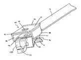
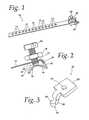
- FIG. 1is a perspective view of an example ground strap assembly
- FIG. 2is an enlarged side, perspective view of an end of the strap assembly of FIG. 1 , but showing the end of the strap assembly from the side with the grounding clip and the threaded member removed;
- FIG. 3is a perspective view of the threaded member of FIG. 1 ;
- FIG. 4is a view similar to FIG. 2 , but including the threaded member
- FIG. 5is a top perspective view of an example grounding clip
- FIG. 6is a bottom perspective view of the grounding clip of FIG. 5 ;
- FIG. 7is a bottom perspective view of the strap assembly of FIG. 1 , but excluding the threaded member, the fastener and the ground nut;
- FIG. 8is an enlarged side, perspective view of an end of the strap assembly of FIG. 1 ;
- FIG. 9is a side view of the ground strap assembly of FIG. 1 mounted on an electrically conductive member shown with the grounding clip removed;
- FIG. 10is a perspective view of the ground strap of FIG. 1 mounted on an electrically conductive member and showing an attached ground wire;
- FIG. 11is a perspective view of a ground strap assembly embodying features of the present invention.
- FIG. 12is an enlarged perspective view of the ground strap of FIG. 11 , showing the end of the strap assembly with the grounding clip and the threaded member removed;
- FIG. 13is an enlarged perspective view of the ground strap of FIG. 11 showing the bendable ground strap and the ground shim;
- FIG. 14is a perspective view of the ground shim of FIG. 13 ;
- FIG. 15is a plan view of the ground shim of FIG. 14 as seen from the underside of the ground shim.
- FIG. 16is a perspective view of the ground strap of FIG. 11 mounted on an electrically conductive member and showing an attached ground wire.
- FIG. 1is a perspective view of an example grounding strap assembly 10 .
- the grounding strap assembly 10is adapted to secure a conductor 11 (see FIG. 10 ) to an electrically conductive structure 13 (see FIGS. 9 and 10 ), such as a plumbing pipe, a mast, etc.
- the grounding strap assembly 10is provided with a bendable ground strap 12 .
- the strap 12may be implemented by a thin strip of galvanized steel, copper, or other conductive metal.
- the ground strap 12is approximately one-half inch wide and several inches long, but persons of ordinary skill in the art will readily appreciate that straps of other dimensions would likewise be appropriate.
- the bendable ground strap 12is penetrated by a series of hook apertures or bores 14 .
- the hook apertures 14are stamped into the strap 12 along a line beginning near a first end of the strap.
- the hook apertures 14are evenly spaced from one another and are centered on the longitudinal center axis of the ground strap 12 .
- a second end of the bendable ground strap 12is formed into an arc 16 as shown in FIG. 2 .
- the bottom surface 18 of the arc 16is intended to mate with an outer circumference of a cylindrical electrically conductive member 13 in a conventional fashion as shown in FIGS. 9 and 10 .
- the ground strap 12is further provided with a threaded member 20 .
- the threaded member 20 of the illustrated exampleincludes a rectilinear body 22 and a hook 24 which extends downwardly and outwardly from the body 22 .
- the body 22is, thus, located in a first plane and the hook 24 includes a point or head 26 which is located in a second plane below the first plane.
- the point 26 of the illustrated hook 24is joined to the body 22 by an S-shaped shank 28 . As shown in FIG. 3 , in the illustrated example the point 26 has a greater width than the shank 28 .
- the body 22 of the threaded member 20defines a threaded bore 30 .
- the threaded bore 30is dimensioned to mate with a fastener 50 as discussed below, and is located at generally the center of the body 22 .
- the threaded bore 30penetrates the entire depth of the body 22 to permit the fastener 50 to pass through the body 22 .
- the threaded member 20may be implemented from any desired material, but in the illustrated example, it is made of galvanized steel.
- the second end of the strap 12is bent downward and backward to define a capture space 36 above the arc 16 . More specifically, the capture space 36 is bounded on three sides by an undersurface portion 38 of the strap 12 , an upper surface 40 of the arc 16 , and a joining segment 42 of the strap 12 coupling the undersurface portion 38 and the arc 16 .
- the joining segment 42defines a bore 44 .
- the bore 44is positioned to receive the hook 24 of the threaded member 20 such that the hook 24 extends through the joining segment 42 of the strap 12 .
- the body 22 and bore 30 of the threaded member 20are located on one side of the joining segment 42 of the strap 12 and the head 26 of the hook 24 is located on an opposite side of the joining segment 42 .
- the ground strap assembly 10is further provided with a fastener 50 .
- the fastener 50passes through a bore 52 defined in the strap 12 (see FIG. 7 ) and threads into the threaded bore 30 of the threaded member 20 .
- the fastener 50may be threaded completely through the threaded bore 30 and into engagement with the upper surface 40 of the arc 16 as shown in FIG. 2 .
- the fastener 50may be implemented by any conventional fastener, but in the illustrate example it is implemented by a brass screw having a slotted hexagonal head.
- the grounding strap assembly 10is further provided with a grounding clip 60 .
- the illustrated grounding clip 60includes a generally planar body 62 .
- the body 62defines a bore 64 for receiving the fastener 50 as explained in further detail below.
- the grounding clip 60is further provided with flanges 68 which extend downwardly from the body 62 . As most easily seen in FIGS. 6 and 7 , the flanges 68 are spaced apart to receive the strap 12 therebetween. When the strap 12 is positioned between the flanges 68 , each of the flanges 68 is immediately adjacent an opposite side of the strap 12 . Engagement of a flange 68 and a side surface of the strap 12 substantially prevents the grounding clip 60 from rotating relative to the strap 12 about the central axis of the bore 64 (i.e., an axis which is substantially perpendicular to the body 62 ).
- the grounding clip 60is further provided with upwardly oriented flanges 70 .
- a first upwardly oriented flange 70is located at a first end of the body 62 and a second upwardly oriented flange 70 is located at a second end opposite the first end of the body 62 .
- the body 62joins the upwardly oriented flanges 70 and the downwardly oriented flanges 68 into a unitary structure.
- the illustrated exampleincludes two upwardly oriented flanges 70 , a different number of such flanges 70 (including, for example, zero, one, three, etc.) may alternatively be employed.
- Two, oppositely disposed flanges 70are currently preferred, however, to facilitate insertion of the ground wire from either side of the grounding clip 60 .
- Making the grounding clip 60 symmetrical with respect to the upwardly oriented flanges 70 and the downwardly oriented flanges 68is also preferred because it simplifies the assembly of the clip 60 to the strap 12 in that the clip 60 may be oriented in either direction without any difference in functionality or appearance.
- the grounding clip 60is mounted to the strap 12 by passing the fastener 50 through the bore 64 of the grounding clip 60 , the bore 52 of the strap 12 , and the threaded bore 30 of the threaded member 20 .
- the grounding clip 60is located adjacent a top surface of the strap 12 and the threaded member 20 is located adjacent a bottom surface of the strap 12 .
- the downwardly extending flanges 68 of the grounding clip 60are located on opposite sides of the bendable ground strap 12
- one of the upwardly oriented flanges 70is located above the strap 12
- the oppositely located, upwardly oriented flange 70is located above the hook 24 .
- a conductor 11can be easily inserted under the upwardly oriented flange 70 and between the grounding clip 60 and the bendable ground strap 12 as shown in FIG. 10 .
- a ground nut 76 carried by the fastener 50may then be tightened down to securely clamp the conductor 11 between the grounding clip 60 and the strap 12 .
- the ground nut 76(which may be implemented by any known nut such as a brass hexagonal nut), is located adjacent the top of the body 62 of the grounding clip 60 .
- the ground nut 76when the ground nut 76 is tightened, it applies a force driving the body 62 of the grounding clip 60 downward toward the upper surface of the strap 12 .
- the undersurface of the body 62presses against the conductor 11 to trap the conductor 11 in electrical contact with the electrically conductive, strap 12 .
- the downwardly oriented flanges 68 of the grounding clip 60ensure that the ground wire does not escape from between the clip 60 and the strap 12 during this tightening process.
- FIG. 9illustrates the grounding strap assembly 10 mounted to an example electrically conductive structure 13 .
- the strap 12is wrapped around the electrically conductive structure 13 with the arc 16 in electrically conductive engagement with an outer surface of the electrically conductive structure 13 .
- one of the hook apertures 14receives the point 26 of the hook 24 .
- the fastener 50is tightened. Tightening the fastener 50 with the end of the fastener 50 engaging the upper surface of the arc 16 causes the undersurface portion 38 of the strap 12 to move away from the arc 16 thereby causing the strap 12 to tighten onto the electrically conductive structure 13 .
- the hook aperture 14 that receives the hook 24may move slightly with respect to the point 26 of the hook 24 during this tightening process as permitted by the reduced width of the shank 28 of the hook 24 to thereby ensure that the strap 12 cannot separate from the hook 24 .
- the grounding strap assembly 10may be secured to the hook 24 without wrapping the strap 12 over the grounding clip 60 , and without removing the fastener 50 from the threaded member 20 .
- the fastener 50only passes through the strap 12 one time when the strap assembly 10 is secured to the electrically conductive grounding member 13 .
- the example grounding strap assembly 10 illustrated hereinmay be secured to an electrically conductive structure 13 without ever removing the fastener 50 from the strap assembly 10 thereby eliminating an installation step and saving users of the strap assembly 10 the labor time associated with that eliminated step.
- the illustrated ground strap assembly 10eliminates the need for overlapping and passing a fastener through the overlapped strap as present in prior art straps, because the shank 28 of the hook 24 extends downward a distance. This downward extension permits the end of the hook 24 to be upwardly inclined at a relatively steep slope. The steep slope of the end of the hook 24 ensures that the strap 12 remains on the hook 24 during tightening. The security of the attachment of the strap 12 and the hook 24 is further enhanced by the presence of the reduced shank segment adjacent the point 26 of the hook 24 . In particular, once the strap 12 begins to tighten, the hole receiving the point 26 of the hook 24 moves off-center with respect to the hook 26 to thereby substantially prevent the hole from sliding back off of the hook 26 .
- the downward extension of the shank 28is also advantageous in that it ensures that the free end of the strap 12 does not interfere with insertion of a conductor 11 beneath the grounding clip 60 .
- a conductor 11can be inserted between the strap 12 and the grounding clip 60 from either of two opposite ends.
- the illustrated grounding strap assembly 10may be secured to an electrically conductive structure 13 in the following manner. First, the grounding clip 60 is fastened to the ground strap 12 with the fastener 50 . This fastening may be performed by the manufacturer such that the installer may not need to handle the assembly 10 with the fastener 50 removed.
- the installerthen engages the electrically conductive structure 13 with an engaging surface of the ground strap 12 such as the arc 16 .
- the installerthen wraps the ground strap 12 around the electrically conductive structure 13 and connects the ground strap 12 to the hook 24 extending from the ground strap 12 .
- the fasteneris tightened to secure the ground strap 12 to the hook 24 .
- a ground wireis inserted between the grounding clip 60 and the ground strap 12 , and the nut 76 is tightened to secure the ground wire beneath the grounding clip 60 in electrically conductive engagement with the ground strap 12 .
- the illustrated strap assembly 10does not require removal of the fastener 50 and/or overlap of the strap 12 at the location of the bore 52 to mount the strap assembly 10 to an electrically conductive member
- persons of ordinary skill in the artwill appreciate that the illustrated example could be modified for use in the overlapping style, if desired.
- the grounding clip 60could be used with an overlapping strap with the grounding clip 60 being mounted adjacent the overlapping sections of the strap if such overlapping is desired.
- a grounding shim 120may be used with the exemplary strap assembly 10 to avoid the connection of two dissimilar metals.
- a connectionmay take place between a conductor, such as a copper wire, attached to the grounding strap assembly 10 and the strap 12 , which may be made of galvanized steel.
- a connection of two dissimilar metalsmay cause a galvanic reaction, especially when moisture is introduced into the connector. That is, a small electric current flows between the two dissimilar metals, causing material to be removed from one of the metals in the form of metal ions. The amount of material removed from one of the metals is partially dependent upon the relative galvanic potentials or galvanic activities of the two metals.
- the grounding shim 120 and grounding clip 60may be formed from copper or brass, which has a galvanic potential similar to copper, in such cases, as these materials would minimize any galvanic corrosion which may occur with a copper conductor attached to the grounding strap assembly.
- the grounding shim 120includes a body 128 defining a bore 126 which receives the fastener 50 .
- the bore 126is located so that it registers with the bore 30 of the threaded member 20 , the bore 64 of the grounding clip 60 , and the bore 52 of the strap 12 .
- the fastener 50may pass through the grounding clip 60 , the grounding shim 120 , and the strap 12 and thread into the threaded member 20 and engage the upper surface 40 of the arc 16 .
- the body 128is further provided with an arcuate, generally L-shaped front portion 122 that defines a cutout 130 which corresponds with the location of the hook 24 of the threaded member 20 . While a generally L-shaped configuration is preferred, those skilled in the art will recognize that any configuration which accommodates the hook 24 , such as differently shaped apertures or cutouts, may be used in place of the L-shaped portion 122 and the cutout 130 .
- the body 128 and the L-shaped front portion 122form an angle which complements the angle between the strap 12 and the adjoining end segment 42 .
- the cutout 130is sized to permit sufficient projection of the hook 24 of the threaded member 20 after the threaded member 20 has been inserted into the capture space 36 of the strap 12 .
- the grounding shim 120is formed from copper or brass, such as from 0.010 inch stiff brass and, when using the grounding shim 120 , the grounding clip 60 also is preferably formed of a similar copper or brass material, such as 0.040 inch hard brass.
- the body 128also includes a hook or receiver 24 which wraps around one of the longitudinal edges of the strap 12 .
- the hook 24acts as a stop and prevents rotation of the grounding shim 120 relative to the strap 12 .
- the hook 24 and the L-shaped portion 122cooperate to limit rotation of the grounding shim 120 relative to the strap 12 .
- the hook 24aids in the insertion of the conductor 11 between the grounding clip 60 and the grounding shim 120 by ensuring that the body 128 of the grounding shim 120 is generally against the strap 12 when the conductor 11 is inserted therebetween.
- the grounding strap assembly 10 using the ground shim 120is secured to an electrically conductive structure 13 .
- the fastener 50passes through the bore 64 of the grounding clip 60 , the bore 126 of the grounding shim 120 , and the bore 52 of the strap 12 , and, then, threads into the threaded bore 30 of the threaded member 20 .
- the downwardly extending flanges 68 of the grounding clip 60are each adjacent one of the opposite longitudinal edges of the strap 12
- one of the upwardly oriented flanges 70extends over the strap 12
- the oppositely located, upwardly oriented flange 70extends above the hook 24 .
- the conductor 11can be easily slid under the upwardly oriented flange 70 and between the grounding clip 60 and the grounding shim 120 , as shown in FIG. 16 .
- the ground nut 76 carried by the fastener 50may then be tightened down to securely clamp the conductor 11 between the grounding clip 60 and the grounding shim 120 . Therefore, the conductor 11 , which is commonly a copper wire, is clamped into electrical contact with the grounding clip 60 and the grounding shim 120 , which are preferably copper or brass. Thus, the conductor 11 is in electrical contact with the same metal or metals with similar activities, which minimizes any galvanic corrosion of the conductor 11 , grounding clip 60 , and the grounding shim 120 . Even in circumstances where some galvanic corrosion occurs, if any, it is minimized because of the larger area of contact between the grounding shim 120 and the strap 12 .
Landscapes
- Electric Cable Installation (AREA)
- Elimination Of Static Electricity (AREA)
Abstract
Description
Claims (35)
Priority Applications (1)
| Application Number | Priority Date | Filing Date | Title |
|---|---|---|---|
| US10/713,442US6933442B2 (en) | 2003-02-12 | 2003-11-14 | Methods and apparatus to secure a ground strap assembly to an electrically conductive member |
Applications Claiming Priority (2)
| Application Number | Priority Date | Filing Date | Title |
|---|---|---|---|
| US10/365,293US6727430B1 (en) | 2003-02-12 | 2003-02-12 | Methods and apparatus to secure a ground strap assembly to an electrically conductive member |
| US10/713,442US6933442B2 (en) | 2003-02-12 | 2003-11-14 | Methods and apparatus to secure a ground strap assembly to an electrically conductive member |
Related Parent Applications (1)
| Application Number | Title | Priority Date | Filing Date |
|---|---|---|---|
| US10/365,293Continuation-In-PartUS6727430B1 (en) | 2003-02-12 | 2003-02-12 | Methods and apparatus to secure a ground strap assembly to an electrically conductive member |
Publications (2)
| Publication Number | Publication Date |
|---|---|
| US20040154818A1 US20040154818A1 (en) | 2004-08-12 |
| US6933442B2true US6933442B2 (en) | 2005-08-23 |
Family
ID=46300341
Family Applications (1)
| Application Number | Title | Priority Date | Filing Date |
|---|---|---|---|
| US10/713,442Expired - LifetimeUS6933442B2 (en) | 2003-02-12 | 2003-11-14 | Methods and apparatus to secure a ground strap assembly to an electrically conductive member |
Country Status (1)
| Country | Link |
|---|---|
| US (1) | US6933442B2 (en) |
Cited By (18)
| Publication number | Priority date | Publication date | Assignee | Title |
|---|---|---|---|---|
| US20060060302A1 (en)* | 2004-09-21 | 2006-03-23 | White John M | RF grounding of cathode in process chamber |
| US20070169497A1 (en)* | 2006-01-20 | 2007-07-26 | United Technologies Corporation | Splash guard with fastener-free attachment for multi-poise furnace coils |
| US20080187682A1 (en)* | 2006-12-20 | 2008-08-07 | Beom Soo Park | Prevention of film deposition on pecvd process chamber wall |
| US20100196626A1 (en)* | 2009-02-04 | 2010-08-05 | Applied Materials, Inc. | Ground return for plasma processes |
| US8106297B1 (en)* | 2009-09-24 | 2012-01-31 | Bridgeport Fittings, Inc. | Grounded conduit bushing |
| US20140224536A1 (en)* | 2011-10-27 | 2014-08-14 | Yazaki Corporation | Electric wire terminal connection structure and intermediary cap used for the same |
| US20150014055A1 (en)* | 2013-07-09 | 2015-01-15 | GM Global Technology Operations LLC | Electrical grounding and structural device for dissimilar metal components |
| US20150093090A1 (en)* | 2012-04-03 | 2015-04-02 | Tyco Electronics Raychem Bvba | Cable clamp and telecommunications enclosure |
| US9070989B2 (en)* | 2012-12-11 | 2015-06-30 | Nabtesco Corporation | Terminal connection joint and terminal block |
| USD739225S1 (en)* | 2013-10-02 | 2015-09-22 | John Mazzie | Ground strap with hooked grounding nut |
| US20160365716A1 (en)* | 2015-06-15 | 2016-12-15 | GM Global Technology Operations LLC | Cable set holder for a motor vehicle and motor vehicle with cable set holder |
| US9768532B1 (en)* | 2016-09-22 | 2017-09-19 | Billy Letkeman | Irrigation system grounding strap |
| US20180340258A1 (en)* | 2017-05-29 | 2018-11-29 | Samsung Display Co., Ltd. | Chemical vapor deposition system |
| US10935748B2 (en) | 2017-04-17 | 2021-03-02 | CommScope Connectivity Belgium BVBA | Modularized cable termination unit |
| US11649910B2 (en) | 2020-03-06 | 2023-05-16 | Erico International Corporation | Systems and methods for a clamp |
| USD996964S1 (en)* | 2020-10-30 | 2023-08-29 | Joshua George SINGH | Clip |
| US11852883B2 (en) | 2012-04-03 | 2023-12-26 | CommScope Connectivity Belgium BVBA | Cable clamp and telecommunications enclosure |
| US11867962B2 (en) | 2019-09-16 | 2024-01-09 | Commscope Technologies Llc | Cable fixation assembly with strength member anchor adapter |
Families Citing this family (11)
| Publication number | Priority date | Publication date | Assignee | Title |
|---|---|---|---|---|
| US10016597B2 (en)* | 2014-10-13 | 2018-07-10 | Scott Newman | Electrostatic grounding apparatus for electrically grounding a mat having an electrically conductive layer |
| AU2016373975B2 (en) | 2015-12-14 | 2021-05-20 | Chatsworth Products, Inc. | Cage nut fastener and methods for tool-less installation of same |
| US10320164B2 (en) | 2016-05-05 | 2019-06-11 | Rxl, Inc. | Grounding clip |
| MX2020005116A (en) | 2017-11-10 | 2020-09-09 | Hubbell Inc | Mechanical grounding clamp. |
| DE102020112829A1 (en)* | 2020-05-12 | 2021-11-18 | Eaton Intelligent Power Limited | Earthing element and electrical installation component with an earthing element |
| US11622458B1 (en) | 2020-12-15 | 2023-04-04 | Chatsworth Products, Inc. | Brush port assembly and method for installing same |
| US12048108B1 (en) | 2020-12-15 | 2024-07-23 | Chatsworth Products, Inc. | Caster attachment system using mating features |
| US11678456B1 (en) | 2020-12-15 | 2023-06-13 | Chatsworth Products, Inc. | Slidable mounting hardware for electronic equipment enclosure and method for installing same |
| US11818860B1 (en) | 2020-12-15 | 2023-11-14 | Chatsworth Products, Inc. | Frame structure for electronic equipment enclosure |
| US11920392B1 (en) | 2021-02-02 | 2024-03-05 | Chatsworth Products, Inc. | Electrical bonding door hinges |
| US11909154B1 (en) | 2021-03-08 | 2024-02-20 | Chatsworth Products, Inc. | Endcap for establishing electrical bonding connection |
Citations (60)
| Publication number | Priority date | Publication date | Assignee | Title |
|---|---|---|---|---|
| US807497A (en) | 1905-03-06 | 1905-12-19 | Henry E Reeve | Binding-post. |
| US846400A (en) | 1906-02-19 | 1907-03-05 | George R Blackburn | Clamp for ground-wire electrical connections. |
| US907542A (en) | 1908-12-22 | Fairmount Electric And Mfg Company | Ground-joint connection for electric conductors. | |
| US972489A (en) | 1909-06-28 | 1910-10-11 | Monroe Electrical Mfg Company | Ground-clamp. |
| US1250467A (en) | 1917-02-01 | 1917-12-18 | Frederick I Johnson | Pipe-clamp. |
| US1418650A (en) | 1920-07-03 | 1922-06-06 | Mary W Johnson | Pipe clamp |
| DE373689C (en)* | 1920-09-12 | 1923-04-14 | J W Dunker G M B H | Pipe clamp |
| US1505314A (en) | 1920-08-19 | 1924-08-19 | Warren R Cox | Electrical grounding clamp |
| US1552932A (en) | 1922-11-18 | 1925-09-08 | Charles L Kessler | Grounding device for electrical conduits |
| US1675163A (en) | 1926-08-13 | 1928-06-26 | Super Ball Antenna Co Inc | Ground clamp |
| CH150427A (en)* | 1930-08-29 | 1931-10-31 | Otto Spirig Karl | Bride for attaching lead cables and electrical lines. |
| US1839254A (en) | 1926-03-11 | 1932-01-05 | Crouse Hinds Co | Conduit outlet box and grounding device |
| US2061463A (en) | 1935-01-02 | 1936-11-17 | United Carr Fastener Corp | Clip member |
| US2114752A (en) | 1936-01-16 | 1938-04-19 | Kearney James R Corp | Ground clamp |
| US2190824A (en) | 1938-02-09 | 1940-02-20 | Reliable Electric Co | Aluminum to copper connector |
| US2210750A (en) | 1938-04-16 | 1940-08-06 | Reliable Electric Co | Aluminum to copper connector |
| US2423627A (en) | 1944-03-15 | 1947-07-08 | Tinnerman Products Inc | Electrical conduit clamp |
| US2532068A (en) | 1948-12-23 | 1950-11-28 | Pelham Electric Mfg Corp | Solderless connector |
| US2681196A (en) | 1949-06-28 | 1954-06-15 | Otto H Lind | Cable holding clip |
| US2795770A (en) | 1953-09-21 | 1957-06-11 | Jasper Blackburn Products Corp | Wire clamp with low-resistance liner |
| US3040477A (en) | 1959-08-26 | 1962-06-26 | Jack W June | Adjustable tree limb holder |
| US3187299A (en) | 1962-04-13 | 1965-06-01 | Square D Co | Electrical connector |
| US3353145A (en) | 1965-06-03 | 1967-11-14 | Northern Electric Co | Electrical grounding clamp |
| US3562701A (en) | 1968-05-15 | 1971-02-09 | Sola Basic Ind Inc | Cable connector |
| US3760342A (en) | 1971-09-17 | 1973-09-18 | Essex International Inc | Terminal construction for electrical conductors |
| US3924920A (en)* | 1974-06-10 | 1975-12-09 | Western Electric Co | Device for clamping elongated member |
| US4002869A (en) | 1975-05-08 | 1977-01-11 | International Telephone And Telegraph Corporation | Automatic high voltage grounding device for personnel safety |
| US4026619A (en) | 1974-09-16 | 1977-05-31 | John T. Thompson | High capacity solderless bonding assembly for shielded cables |
| US4103986A (en) | 1977-09-12 | 1978-08-01 | Thomas & Betts Corporation | Electrical terminal |
| USD269155S (en) | 1980-09-22 | 1983-05-31 | The Boeing Company | Clamp or the like |
| US4526428A (en)* | 1984-03-30 | 1985-07-02 | Isaac Sachs | Multi-strand cable clamp with positive strand engagement |
| US4591229A (en) | 1982-12-10 | 1986-05-27 | Isaac Sachs | Grounding strap |
| US4623204A (en) | 1984-05-17 | 1986-11-18 | Auclair William T | Universal ground clamp |
| US4626051A (en) | 1985-07-18 | 1986-12-02 | Franks George J Jr | Universal ground clamp |
| US4664469A (en) | 1985-02-19 | 1987-05-12 | Isaac Sachs | Grounding strap |
| US4780096A (en) | 1987-09-08 | 1988-10-25 | Franks George J Jr | Ground clamp |
| US4828504A (en) | 1987-11-05 | 1989-05-09 | Franks George J Jr | Clamp |
| USD301303S (en) | 1986-04-21 | 1989-05-30 | Hoover Robert J | Anchor rope guard |
| US4925395A (en) | 1987-11-05 | 1990-05-15 | Franks George J Jr | Clamp for electrically conductive strips |
| US4944683A (en) | 1989-11-13 | 1990-07-31 | A K Stamping Co., Inc. | Grounding clamp |
| USD313392S (en) | 1988-06-13 | 1991-01-01 | Isaac Sachs | Grounding strap for metal pipes |
| US4993960A (en) | 1987-11-05 | 1991-02-19 | Franks George J Jr | Grounding system and clamp |
| US5006074A (en) | 1987-11-05 | 1991-04-09 | Franks George J Jr | Adjustable ground clamp |
| USD323973S (en) | 1989-06-15 | 1992-02-18 | Isaac Sachs | Ground connector strap |
| USD323974S (en) | 1989-06-15 | 1992-02-18 | Isaac Sachs | Support bracket for poles of circular cross-section |
| US5131856A (en) | 1991-11-15 | 1992-07-21 | Electric Motion Company, Incorporated | Universal ground clamp |
| USD331358S (en) | 1991-01-18 | 1992-12-01 | Isaac Sachs | Cable clip |
| USD335079S (en) | 1992-06-10 | 1993-04-27 | Isaac Sachs | Attachment clamp |
| USD342013S (en) | 1992-03-24 | 1993-12-07 | Isaac Sachs | Cable clip |
| US5314343A (en) | 1993-06-30 | 1994-05-24 | Rosco, Inc. | Grounding strap |
| US5616036A (en) | 1995-10-27 | 1997-04-01 | Thomas Polidori | Grounding clamp |
| US5642739A (en) | 1994-04-11 | 1997-07-01 | Fareed; Donald O. | Magnetic arm band for tennis elbow |
| US5674079A (en)* | 1995-05-31 | 1997-10-07 | Electric Motion Company, Inc. | Ground lug |
| US5768036A (en) | 1992-04-20 | 1998-06-16 | Asahi Kogaku Kogyo Kabushiki Kaisha | Beam receiving position adjusting device |
| USD398218S (en) | 1997-09-05 | 1998-09-15 | Diamond Communication Products, Inc. | Cable clip and fastener combination |
| US6011218A (en) | 1995-09-20 | 2000-01-04 | Lucent Technologies, Inc. | U-shaped universal grounding clamp |
| US6322378B1 (en) | 1999-12-14 | 2001-11-27 | Electric Motion Company, Inc. | Conductor protector for ground clamp |
| US6398596B1 (en) | 1998-12-18 | 2002-06-04 | Allied Bolt, Inc. | Ground clamp |
| US6475038B1 (en) | 1999-10-27 | 2002-11-05 | Patent-Treuhand-Gesellschaft Fuer Elektrische Gluehlampen Mbh | Connector terminal |
| US6652295B1 (en)* | 1997-02-28 | 2003-11-25 | Maris Anthony Glass | Ground bus for junction box |
Family Cites Families (37)
| Publication number | Priority date | Publication date | Assignee | Title |
|---|---|---|---|---|
| US131856A (en)* | 1872-10-01 | Improvement in razor-strops | ||
| US269155A (en)* | 1882-12-12 | Washing-machine | ||
| US335079A (en)* | 1886-01-26 | Heney w | ||
| US616036A (en)* | 1898-12-13 | Richard thompson | ||
| US313392A (en)* | 1885-03-03 | Running-gear for vehicles | ||
| US314343A (en)* | 1885-03-24 | Machine | ||
| US61463A (en)* | 1867-01-22 | John robertson | ||
| US233733A (en)* | 1880-10-26 | cornell | ||
| US250467A (en)* | 1881-12-06 | Seth wheelee | ||
| US323974A (en)* | 1885-08-11 | thompson | ||
| US331358A (en)* | 1885-12-01 | Harrow attachment for plows | ||
| US532068A (en)* | 1895-01-08 | Middlings-purifier | ||
| US423627A (en)* | 1890-03-18 | Automatic gill-net puller | ||
| US626051A (en)* | 1899-05-30 | Buckle-shield | ||
| US323973A (en)* | 1885-08-11 | Wagon-body | ||
| US418650A (en)* | 1889-12-31 | Vehicle | ||
| US398218A (en)* | 1889-02-19 | William charles bayless and james gumming nichols | ||
| US505314A (en)* | 1893-09-19 | Game-board | ||
| US26619A (en)* | 1859-12-27 | Improvement in steam-engines for land-carriages | ||
| US342013A (en)* | 1886-05-18 | Chables w | ||
| US591229A (en)* | 1897-10-05 | Pump for pneumatic tires | ||
| US552932A (en)* | 1896-01-14 | Bridle-bit | ||
| US301303A (en)* | 1884-07-01 | Tjiomas tayloe | ||
| US398596A (en)* | 1889-02-26 | Wire-stretcher | ||
| US103986A (en)* | 1870-06-07 | Improvement in electrical cotton-picking machines | ||
| US6074A (en)* | 1849-01-30 | Machine fob making suspender-buckles | ||
| US623204A (en)* | 1899-04-18 | Webster | ||
| US114752A (en)* | 1871-05-16 | Improvement in paper boxes | ||
| US664469A (en)* | 1897-05-20 | 1900-12-25 | American Bicycle Company | Joint for vehicle-frames. |
| US839254A (en)* | 1898-04-09 | 1906-12-25 | George D Mumford | Automatic inkstand. |
| US675163A (en)* | 1900-10-01 | 1901-05-28 | Willis E Overton | Steam-cooker for fertilizers. |
| US681196A (en)* | 1900-11-05 | 1901-08-27 | Erving D Clark | Tubular metallic frame. |
| US780096A (en)* | 1902-04-02 | 1905-01-17 | Hermann Geppert | Absorption refrigerating apparatus. |
| US828504A (en)* | 1906-03-07 | 1906-08-14 | Daniel V C Rapp | Seed-distributer. |
| US925395A (en)* | 1908-09-19 | 1909-06-15 | Harry Hobdell | Safety-switch. |
| US944683A (en)* | 1908-10-12 | 1909-12-28 | Leo D Mager | Feed-valve for steam-boilers. |
| US993960A (en)* | 1909-09-07 | 1911-05-30 | James H Carlton | Rotary engine. |
- 2003
- 2003-11-14USUS10/713,442patent/US6933442B2/ennot_activeExpired - Lifetime
Patent Citations (60)
| Publication number | Priority date | Publication date | Assignee | Title |
|---|---|---|---|---|
| US907542A (en) | 1908-12-22 | Fairmount Electric And Mfg Company | Ground-joint connection for electric conductors. | |
| US807497A (en) | 1905-03-06 | 1905-12-19 | Henry E Reeve | Binding-post. |
| US846400A (en) | 1906-02-19 | 1907-03-05 | George R Blackburn | Clamp for ground-wire electrical connections. |
| US972489A (en) | 1909-06-28 | 1910-10-11 | Monroe Electrical Mfg Company | Ground-clamp. |
| US1250467A (en) | 1917-02-01 | 1917-12-18 | Frederick I Johnson | Pipe-clamp. |
| US1418650A (en) | 1920-07-03 | 1922-06-06 | Mary W Johnson | Pipe clamp |
| US1505314A (en) | 1920-08-19 | 1924-08-19 | Warren R Cox | Electrical grounding clamp |
| DE373689C (en)* | 1920-09-12 | 1923-04-14 | J W Dunker G M B H | Pipe clamp |
| US1552932A (en) | 1922-11-18 | 1925-09-08 | Charles L Kessler | Grounding device for electrical conduits |
| US1839254A (en) | 1926-03-11 | 1932-01-05 | Crouse Hinds Co | Conduit outlet box and grounding device |
| US1675163A (en) | 1926-08-13 | 1928-06-26 | Super Ball Antenna Co Inc | Ground clamp |
| CH150427A (en)* | 1930-08-29 | 1931-10-31 | Otto Spirig Karl | Bride for attaching lead cables and electrical lines. |
| US2061463A (en) | 1935-01-02 | 1936-11-17 | United Carr Fastener Corp | Clip member |
| US2114752A (en) | 1936-01-16 | 1938-04-19 | Kearney James R Corp | Ground clamp |
| US2190824A (en) | 1938-02-09 | 1940-02-20 | Reliable Electric Co | Aluminum to copper connector |
| US2210750A (en) | 1938-04-16 | 1940-08-06 | Reliable Electric Co | Aluminum to copper connector |
| US2423627A (en) | 1944-03-15 | 1947-07-08 | Tinnerman Products Inc | Electrical conduit clamp |
| US2532068A (en) | 1948-12-23 | 1950-11-28 | Pelham Electric Mfg Corp | Solderless connector |
| US2681196A (en) | 1949-06-28 | 1954-06-15 | Otto H Lind | Cable holding clip |
| US2795770A (en) | 1953-09-21 | 1957-06-11 | Jasper Blackburn Products Corp | Wire clamp with low-resistance liner |
| US3040477A (en) | 1959-08-26 | 1962-06-26 | Jack W June | Adjustable tree limb holder |
| US3187299A (en) | 1962-04-13 | 1965-06-01 | Square D Co | Electrical connector |
| US3353145A (en) | 1965-06-03 | 1967-11-14 | Northern Electric Co | Electrical grounding clamp |
| US3562701A (en) | 1968-05-15 | 1971-02-09 | Sola Basic Ind Inc | Cable connector |
| US3760342A (en) | 1971-09-17 | 1973-09-18 | Essex International Inc | Terminal construction for electrical conductors |
| US3924920A (en)* | 1974-06-10 | 1975-12-09 | Western Electric Co | Device for clamping elongated member |
| US4026619A (en) | 1974-09-16 | 1977-05-31 | John T. Thompson | High capacity solderless bonding assembly for shielded cables |
| US4002869A (en) | 1975-05-08 | 1977-01-11 | International Telephone And Telegraph Corporation | Automatic high voltage grounding device for personnel safety |
| US4103986A (en) | 1977-09-12 | 1978-08-01 | Thomas & Betts Corporation | Electrical terminal |
| USD269155S (en) | 1980-09-22 | 1983-05-31 | The Boeing Company | Clamp or the like |
| US4591229A (en) | 1982-12-10 | 1986-05-27 | Isaac Sachs | Grounding strap |
| US4526428A (en)* | 1984-03-30 | 1985-07-02 | Isaac Sachs | Multi-strand cable clamp with positive strand engagement |
| US4623204A (en) | 1984-05-17 | 1986-11-18 | Auclair William T | Universal ground clamp |
| US4664469A (en) | 1985-02-19 | 1987-05-12 | Isaac Sachs | Grounding strap |
| US4626051A (en) | 1985-07-18 | 1986-12-02 | Franks George J Jr | Universal ground clamp |
| USD301303S (en) | 1986-04-21 | 1989-05-30 | Hoover Robert J | Anchor rope guard |
| US4780096A (en) | 1987-09-08 | 1988-10-25 | Franks George J Jr | Ground clamp |
| US4828504A (en) | 1987-11-05 | 1989-05-09 | Franks George J Jr | Clamp |
| US4925395A (en) | 1987-11-05 | 1990-05-15 | Franks George J Jr | Clamp for electrically conductive strips |
| US4993960A (en) | 1987-11-05 | 1991-02-19 | Franks George J Jr | Grounding system and clamp |
| US5006074A (en) | 1987-11-05 | 1991-04-09 | Franks George J Jr | Adjustable ground clamp |
| USD313392S (en) | 1988-06-13 | 1991-01-01 | Isaac Sachs | Grounding strap for metal pipes |
| USD323973S (en) | 1989-06-15 | 1992-02-18 | Isaac Sachs | Ground connector strap |
| USD323974S (en) | 1989-06-15 | 1992-02-18 | Isaac Sachs | Support bracket for poles of circular cross-section |
| US4944683A (en) | 1989-11-13 | 1990-07-31 | A K Stamping Co., Inc. | Grounding clamp |
| USD331358S (en) | 1991-01-18 | 1992-12-01 | Isaac Sachs | Cable clip |
| US5131856A (en) | 1991-11-15 | 1992-07-21 | Electric Motion Company, Incorporated | Universal ground clamp |
| USD342013S (en) | 1992-03-24 | 1993-12-07 | Isaac Sachs | Cable clip |
| US5768036A (en) | 1992-04-20 | 1998-06-16 | Asahi Kogaku Kogyo Kabushiki Kaisha | Beam receiving position adjusting device |
| USD335079S (en) | 1992-06-10 | 1993-04-27 | Isaac Sachs | Attachment clamp |
| US5314343A (en) | 1993-06-30 | 1994-05-24 | Rosco, Inc. | Grounding strap |
| US5642739A (en) | 1994-04-11 | 1997-07-01 | Fareed; Donald O. | Magnetic arm band for tennis elbow |
| US5674079A (en)* | 1995-05-31 | 1997-10-07 | Electric Motion Company, Inc. | Ground lug |
| US6011218A (en) | 1995-09-20 | 2000-01-04 | Lucent Technologies, Inc. | U-shaped universal grounding clamp |
| US5616036A (en) | 1995-10-27 | 1997-04-01 | Thomas Polidori | Grounding clamp |
| US6652295B1 (en)* | 1997-02-28 | 2003-11-25 | Maris Anthony Glass | Ground bus for junction box |
| USD398218S (en) | 1997-09-05 | 1998-09-15 | Diamond Communication Products, Inc. | Cable clip and fastener combination |
| US6398596B1 (en) | 1998-12-18 | 2002-06-04 | Allied Bolt, Inc. | Ground clamp |
| US6475038B1 (en) | 1999-10-27 | 2002-11-05 | Patent-Treuhand-Gesellschaft Fuer Elektrische Gluehlampen Mbh | Connector terminal |
| US6322378B1 (en) | 1999-12-14 | 2001-11-27 | Electric Motion Company, Inc. | Conductor protector for ground clamp |
Non-Patent Citations (5)
| Title |
|---|
| Allied Bolt, Inc. Drop Wire Hard Ware, Product Catalog, undated, p. 37. no date. |
| Three photographs of Allied Bolt ground clamp corresponding to U.S. Appl. No. 6,398,596, 3 pages. Note: photographs are very poor & not readable. |
| Three photographs of Diamond ground strap 3C36, undated, 3 pages. not readable. |
| Three photographs of Electric Motion ground strap UL FM 5510 DB, undated, 3 pages. no date. |
| Three photographs of Sachs ground strap UL 99N9, undated, 3 pages. no date. |
Cited By (29)
| Publication number | Priority date | Publication date | Assignee | Title |
|---|---|---|---|---|
| US20060060302A1 (en)* | 2004-09-21 | 2006-03-23 | White John M | RF grounding of cathode in process chamber |
| US7534301B2 (en) | 2004-09-21 | 2009-05-19 | Applied Materials, Inc. | RF grounding of cathode in process chamber |
| US20090178617A1 (en)* | 2004-09-21 | 2009-07-16 | White John M | Rf grounding of cathode in process chamber |
| US20070169497A1 (en)* | 2006-01-20 | 2007-07-26 | United Technologies Corporation | Splash guard with fastener-free attachment for multi-poise furnace coils |
| US20080187682A1 (en)* | 2006-12-20 | 2008-08-07 | Beom Soo Park | Prevention of film deposition on pecvd process chamber wall |
| US8381677B2 (en) | 2006-12-20 | 2013-02-26 | Applied Materials, Inc. | Prevention of film deposition on PECVD process chamber wall |
| US20100196626A1 (en)* | 2009-02-04 | 2010-08-05 | Applied Materials, Inc. | Ground return for plasma processes |
| US9382621B2 (en) | 2009-02-04 | 2016-07-05 | Applied Materials, Inc. | Ground return for plasma processes |
| US8106297B1 (en)* | 2009-09-24 | 2012-01-31 | Bridgeport Fittings, Inc. | Grounded conduit bushing |
| US9263825B2 (en)* | 2011-10-27 | 2016-02-16 | Yazaki Corporation | Electric wire terminal connection structure and intermediary cap used for the same |
| US20140224536A1 (en)* | 2011-10-27 | 2014-08-14 | Yazaki Corporation | Electric wire terminal connection structure and intermediary cap used for the same |
| US10379310B2 (en)* | 2012-04-03 | 2019-08-13 | CommScope Connectivity Belgium BVBA | Cable clamp and telecommunications enclosure |
| US11852883B2 (en) | 2012-04-03 | 2023-12-26 | CommScope Connectivity Belgium BVBA | Cable clamp and telecommunications enclosure |
| US11092768B2 (en) | 2012-04-03 | 2021-08-17 | CommScope Connectivity Belgium BVBA | Cable clamp and telecommunications enclosure |
| US20150093090A1 (en)* | 2012-04-03 | 2015-04-02 | Tyco Electronics Raychem Bvba | Cable clamp and telecommunications enclosure |
| US9070989B2 (en)* | 2012-12-11 | 2015-06-30 | Nabtesco Corporation | Terminal connection joint and terminal block |
| US20150014055A1 (en)* | 2013-07-09 | 2015-01-15 | GM Global Technology Operations LLC | Electrical grounding and structural device for dissimilar metal components |
| US9083089B2 (en)* | 2013-07-09 | 2015-07-14 | GM Global Technology Operations LLC | Electrical grounding and structural device for dissimilar metal components |
| USD739225S1 (en)* | 2013-10-02 | 2015-09-22 | John Mazzie | Ground strap with hooked grounding nut |
| US9735559B2 (en)* | 2015-06-15 | 2017-08-15 | GM Global Technology Operations LLC | Cable set holder for a motor vehicle and motor vehicle with cable set holder |
| US20160365716A1 (en)* | 2015-06-15 | 2016-12-15 | GM Global Technology Operations LLC | Cable set holder for a motor vehicle and motor vehicle with cable set holder |
| US9768532B1 (en)* | 2016-09-22 | 2017-09-19 | Billy Letkeman | Irrigation system grounding strap |
| US10935748B2 (en) | 2017-04-17 | 2021-03-02 | CommScope Connectivity Belgium BVBA | Modularized cable termination unit |
| US20180340258A1 (en)* | 2017-05-29 | 2018-11-29 | Samsung Display Co., Ltd. | Chemical vapor deposition system |
| US11214870B2 (en)* | 2017-05-29 | 2022-01-04 | Samsung Display Co., Ltd. | Chemical vapor deposition system including ground strap bar |
| US11867962B2 (en) | 2019-09-16 | 2024-01-09 | Commscope Technologies Llc | Cable fixation assembly with strength member anchor adapter |
| US11649910B2 (en) | 2020-03-06 | 2023-05-16 | Erico International Corporation | Systems and methods for a clamp |
| US12215809B2 (en) | 2020-03-06 | 2025-02-04 | Erico International Corporation | Systems and methods for a clamp |
| USD996964S1 (en)* | 2020-10-30 | 2023-08-29 | Joshua George SINGH | Clip |
Also Published As
| Publication number | Publication date |
|---|---|
| US20040154818A1 (en) | 2004-08-12 |
Similar Documents
| Publication | Publication Date | Title |
|---|---|---|
| US6933442B2 (en) | Methods and apparatus to secure a ground strap assembly to an electrically conductive member | |
| US8894424B2 (en) | Universal clip apparatus for solar panel assembly | |
| US6398596B1 (en) | Ground clamp | |
| US5620290A (en) | Ground retainer | |
| US4973259A (en) | Ground connector for shielded cable | |
| JP3406509B2 (en) | Freely rotating ground coupling for external ground as a mounting part | |
| US7597516B2 (en) | Bonding fastener | |
| US7666024B2 (en) | Spring loaded parallel pad clamp | |
| US6727430B1 (en) | Methods and apparatus to secure a ground strap assembly to an electrically conductive member | |
| US8512070B2 (en) | Spring loaded clamp | |
| US4664469A (en) | Grounding strap | |
| US6244517B1 (en) | System for fixing an electric terminal connector | |
| US8287319B2 (en) | Clamp for male terminal | |
| EP0262499A1 (en) | Electrical earth connection device, particularly for vehicles | |
| US5314343A (en) | Grounding strap | |
| CA1099355A (en) | Cable grounding system | |
| US4591229A (en) | Grounding strap | |
| US5055056A (en) | Ground wire connector | |
| RU2581030C2 (en) | Connector for grounding of electrical component supplied with direct current | |
| US6293812B1 (en) | Electrical connector contact bridge with wire clamp | |
| CA2544877C (en) | Lawn and garden battery clamp | |
| US5679032A (en) | Strain relief device for clamp assembly | |
| US3963299A (en) | Bonding assembly for installation on a shielded cable | |
| US7345240B2 (en) | Tamper resistant electrical ground block | |
| US20150140872A1 (en) | Battery Cable Connector with Open Back Handle |
Legal Events
| Date | Code | Title | Description |
|---|---|---|---|
| AS | Assignment | Owner name:SENIOR INDUSTRIES, INC., ILLINOIS Free format text:ASSIGNMENT OF ASSIGNORS INTEREST;ASSIGNOR:FRANKS, JR., GEORGE J.;REEL/FRAME:014705/0690 Effective date:20031110 | |
| STCF | Information on status: patent grant | Free format text:PATENTED CASE | |
| FPAY | Fee payment | Year of fee payment:4 | |
| FPAY | Fee payment | Year of fee payment:8 | |
| AS | Assignment | Owner name:MACLEAN SENIOR INDUSTRIES, L.L.C., ILLINOIS Free format text:ASSIGNMENT OF ASSIGNORS INTEREST;ASSIGNOR:SENIOR INDUSTRIES, INC.;REEL/FRAME:033488/0144 Effective date:20121210 | |
| FPAY | Fee payment | Year of fee payment:12 | |
| SULP | Surcharge for late payment | Year of fee payment:11 | |
| AS | Assignment | Owner name:ARES CAPITAL CORPORATION, AS COLLATERAL AGENT, VIR Free format text:SECURITY INTEREST;ASSIGNOR:MACLEAN SENIOR INDUSTRIES, L.L.C.;REEL/FRAME:047844/0785 Effective date:20181221 | |
| AS | Assignment | Owner name:BANK OF AMERICA, N.A., AS ABL COLLATERAL AGENT, WI Free format text:SECURITY INTEREST;ASSIGNOR:MACLEAN SENIOR INDUSTRIES, L.L.C.;REEL/FRAME:047856/0366 Effective date:20181221 | |
| AS | Assignment | Owner name:WELLS FARGO BANK, NATIONAL ASSOCIATION, ILLINOIS Free format text:SECURITY INTEREST;ASSIGNORS:MACLEAN POWER, L.L.C.;MACLEAN SENIOR INDUSTRIES, L.L.C.;REEL/FRAME:061376/0942 Effective date:20221011 | |
| AS | Assignment | Owner name:MACLEAN SENIOR INDUSTRIES, L.L.C., ILLINOIS Free format text:RELEASE OF SECURITY INTEREST IN INTELLECTUAL PROPERTY COLLATERAL;ASSIGNOR:ARES CAPITAL CORPORATION;REEL/FRAME:061658/0161 Effective date:20221011 Owner name:MACLEAN POWER, L.L.C., ILLINOIS Free format text:RELEASE OF SECURITY INTEREST IN INTELLECTUAL PROPERTY COLLATERAL;ASSIGNOR:ARES CAPITAL CORPORATION;REEL/FRAME:061658/0161 Effective date:20221011 Owner name:MAC LEAN-FOGG COMPANY, ILLINOIS Free format text:RELEASE OF SECURITY INTEREST IN INTELLECTUAL PROPERTY COLLATERAL;ASSIGNOR:ARES CAPITAL CORPORATION;REEL/FRAME:061658/0161 Effective date:20221011 Owner name:MACLEAN SENIOR INDUSTRIES, L.L.C., ILLINOIS Free format text:PARTIAL RELEASE OF SECURITY INTEREST IN INTELLECTUAL PROPERTY COLLATERAL;ASSIGNOR:BANK OF AMERICA, N.A., AS ABL COLLATERAL AGENT;REEL/FRAME:061661/0798 Effective date:20221011 Owner name:MACLEAN POWER, L.L.C., ILLINOIS Free format text:PARTIAL RELEASE OF SECURITY INTEREST IN INTELLECTUAL PROPERTY COLLATERAL;ASSIGNOR:BANK OF AMERICA, N.A., AS ABL COLLATERAL AGENT;REEL/FRAME:061661/0798 Effective date:20221011 Owner name:MAC LEAN-FOGG COMPANY, ILLINOIS Free format text:PARTIAL RELEASE OF SECURITY INTEREST IN INTELLECTUAL PROPERTY COLLATERAL;ASSIGNOR:BANK OF AMERICA, N.A., AS ABL COLLATERAL AGENT;REEL/FRAME:061661/0798 Effective date:20221011 | |
| AS | Assignment | Owner name:ARES CAPITAL CORPORATION, AS THE COLLATERAL AGENT, VIRGINIA Free format text:SECURITY INTEREST;ASSIGNORS:MACLEAN POWER, L.L.C.;MACLEAN SENIOR INDUSTRIES, L.L.C.;REEL/FRAME:061425/0885 Effective date:20221011 |