US6932843B2 - Apparatus and method for the in-situ formation of a structural prosthesis - Google Patents
Apparatus and method for the in-situ formation of a structural prosthesisDownload PDFInfo
- Publication number
- US6932843B2 US6932843B2US10/255,161US25516102AUS6932843B2US 6932843 B2US6932843 B2US 6932843B2US 25516102 AUS25516102 AUS 25516102AUS 6932843 B2US6932843 B2US 6932843B2
- Authority
- US
- United States
- Prior art keywords
- balloon
- recited
- tubular member
- wall
- line
- Prior art date
- Legal status (The legal status is an assumption and is not a legal conclusion. Google has not performed a legal analysis and makes no representation as to the accuracy of the status listed.)
- Expired - Lifetime
Links
- 238000010952in-situ formationMethods0.000titleclaimsabstractdescription10
- 238000000034methodMethods0.000titleclaimsdescription30
- 239000012620biological materialSubstances0.000claimsabstractdescription57
- OSGAYBCDTDRGGQ-UHFFFAOYSA-Lcalcium sulfateChemical compound[Ca+2].[O-]S([O-])(=O)=OOSGAYBCDTDRGGQ-UHFFFAOYSA-L0.000claimsdescription8
- 238000004891communicationMethods0.000claimsdescription7
- 239000012530fluidSubstances0.000claimsdescription6
- 238000002844meltingMethods0.000claimsdescription5
- 230000008018meltingEffects0.000claimsdescription5
- BVKZGUZCCUSVTD-UHFFFAOYSA-LCarbonateChemical compound[O-]C([O-])=OBVKZGUZCCUSVTD-UHFFFAOYSA-L0.000claimsdescription4
- NIXOWILDQLNWCW-UHFFFAOYSA-Nacrylic acid groupChemical groupC(C=C)(=O)ONIXOWILDQLNWCW-UHFFFAOYSA-N0.000claimsdescription4
- 229910000389calcium phosphateInorganic materials0.000claimsdescription4
- 239000001506calcium phosphateSubstances0.000claimsdescription4
- 235000011010calcium phosphatesNutrition0.000claimsdescription4
- 229910052751metalInorganic materials0.000claimsdescription4
- 239000002184metalSubstances0.000claimsdescription4
- 229920002635polyurethanePolymers0.000claimsdescription4
- 239000004814polyurethaneSubstances0.000claimsdescription4
- QORWJWZARLRLPR-UHFFFAOYSA-Htricalcium bis(phosphate)Chemical compound[Ca+2].[Ca+2].[Ca+2].[O-]P([O-])([O-])=O.[O-]P([O-])([O-])=OQORWJWZARLRLPR-UHFFFAOYSA-H0.000claimsdescription4
- 238000010438heat treatmentMethods0.000claimsdescription3
- 239000000017hydrogelSubstances0.000claimsdescription3
- 229920000642polymerPolymers0.000claims1
- 239000000463materialSubstances0.000description17
- 230000009969flowable effectEffects0.000description8
- 238000011065in-situ storageMethods0.000description6
- 239000000835fiberSubstances0.000description4
- 230000008439repair processEffects0.000description4
- 230000003412degenerative effectEffects0.000description3
- 230000033001locomotionEffects0.000description3
- 239000004698PolyethyleneSubstances0.000description2
- 208000002847Surgical WoundDiseases0.000description2
- 239000000654additiveSubstances0.000description2
- 239000000853adhesiveSubstances0.000description2
- 230000001070adhesive effectEffects0.000description2
- 210000003484anatomyAnatomy0.000description2
- 238000013459approachMethods0.000description2
- 230000003416augmentationEffects0.000description2
- 238000005452bendingMethods0.000description2
- 230000015572biosynthetic processEffects0.000description2
- 210000000988bone and boneAnatomy0.000description2
- 230000004927fusionEffects0.000description2
- 239000004033plasticSubstances0.000description2
- 229920003023plasticPolymers0.000description2
- -1polyethylenePolymers0.000description2
- 229920000573polyethylenePolymers0.000description2
- 230000008569processEffects0.000description2
- 238000011084recoveryMethods0.000description2
- 230000000717retained effectEffects0.000description2
- 230000003068static effectEffects0.000description2
- 208000008035Back PainDiseases0.000description1
- 229920000049Carbon (fiber)Polymers0.000description1
- 102000008186CollagenHuman genes0.000description1
- 108010035532CollagenProteins0.000description1
- 206010016654FibrosisDiseases0.000description1
- 208000003618Intervertebral Disc DisplacementDiseases0.000description1
- 230000032683agingEffects0.000description1
- 238000002399angioplastyMethods0.000description1
- 239000004917carbon fiberSubstances0.000description1
- 229920001436collagenPolymers0.000description1
- 239000004020conductorSubstances0.000description1
- 229920001577copolymerPolymers0.000description1
- 230000003247decreasing effectEffects0.000description1
- 230000018044dehydrationEffects0.000description1
- 238000006297dehydration reactionMethods0.000description1
- 238000005516engineering processMethods0.000description1
- 238000001125extrusionMethods0.000description1
- 230000004761fibrosisEffects0.000description1
- 238000010304firingMethods0.000description1
- 239000003365glass fiberSubstances0.000description1
- 239000007943implantSubstances0.000description1
- 208000015181infectious diseaseDiseases0.000description1
- 238000002347injectionMethods0.000description1
- 239000007924injectionSubstances0.000description1
- 238000003780insertionMethods0.000description1
- 230000037431insertionEffects0.000description1
- 238000009413insulationMethods0.000description1
- 210000003041ligamentAnatomy0.000description1
- 239000000155meltSubstances0.000description1
- 230000004048modificationEffects0.000description1
- 238000012986modificationMethods0.000description1
- 210000003205muscleAnatomy0.000description1
- 210000005036nerveAnatomy0.000description1
- 229920001778nylonPolymers0.000description1
- 230000003287optical effectEffects0.000description1
- 230000002188osteogenic effectEffects0.000description1
- 229920000515polycarbonatePolymers0.000description1
- 239000004417polycarbonateSubstances0.000description1
- 229920000728polyesterPolymers0.000description1
- 229920000139polyethylene terephthalatePolymers0.000description1
- 229920000098polyolefinPolymers0.000description1
- 230000002787reinforcementEffects0.000description1
- 238000002271resectionMethods0.000description1
- 210000003491skinAnatomy0.000description1
- 210000000278spinal cordAnatomy0.000description1
- 230000001954sterilising effectEffects0.000description1
- 238000004659sterilization and disinfectionMethods0.000description1
- 230000035882stressEffects0.000description1
- 238000001356surgical procedureMethods0.000description1
- 229920002994synthetic fiberPolymers0.000description1
- 210000002435tendonAnatomy0.000description1
- BFKJFAAPBSQJPD-UHFFFAOYSA-NtetrafluoroetheneChemical groupFC(F)=C(F)FBFKJFAAPBSQJPD-UHFFFAOYSA-N0.000description1
- 210000001519tissueAnatomy0.000description1
- 238000002604ultrasonographyMethods0.000description1
- 238000007794visualization techniqueMethods0.000description1
- 238000003466weldingMethods0.000description1
Images


Classifications
- A—HUMAN NECESSITIES
- A61—MEDICAL OR VETERINARY SCIENCE; HYGIENE
- A61B—DIAGNOSIS; SURGERY; IDENTIFICATION
- A61B17/00—Surgical instruments, devices or methods
- A61B17/56—Surgical instruments or methods for treatment of bones or joints; Devices specially adapted therefor
- A61B17/58—Surgical instruments or methods for treatment of bones or joints; Devices specially adapted therefor for osteosynthesis, e.g. bone plates, screws or setting implements
- A61B17/88—Osteosynthesis instruments; Methods or means for implanting or extracting internal or external fixation devices
- A61B17/8802—Equipment for handling bone cement or other fluid fillers
- A61B17/8805—Equipment for handling bone cement or other fluid fillers for introducing fluid filler into bone or extracting it
- A61B17/8811—Equipment for handling bone cement or other fluid fillers for introducing fluid filler into bone or extracting it characterised by the introducer tip, i.e. the part inserted into or onto the bone
- A—HUMAN NECESSITIES
- A61—MEDICAL OR VETERINARY SCIENCE; HYGIENE
- A61B—DIAGNOSIS; SURGERY; IDENTIFICATION
- A61B17/00—Surgical instruments, devices or methods
- A61B17/56—Surgical instruments or methods for treatment of bones or joints; Devices specially adapted therefor
- A61B17/58—Surgical instruments or methods for treatment of bones or joints; Devices specially adapted therefor for osteosynthesis, e.g. bone plates, screws or setting implements
- A61B17/88—Osteosynthesis instruments; Methods or means for implanting or extracting internal or external fixation devices
- A61B17/885—Tools for expanding or compacting bones or discs or cavities therein
- A61B17/8852—Tools for expanding or compacting bones or discs or cavities therein capable of being assembled or enlarged, or changing shape, inside the bone or disc
- A61B17/8855—Tools for expanding or compacting bones or discs or cavities therein capable of being assembled or enlarged, or changing shape, inside the bone or disc inflatable, e.g. kyphoplasty balloons
- A—HUMAN NECESSITIES
- A61—MEDICAL OR VETERINARY SCIENCE; HYGIENE
- A61F—FILTERS IMPLANTABLE INTO BLOOD VESSELS; PROSTHESES; DEVICES PROVIDING PATENCY TO, OR PREVENTING COLLAPSING OF, TUBULAR STRUCTURES OF THE BODY, e.g. STENTS; ORTHOPAEDIC, NURSING OR CONTRACEPTIVE DEVICES; FOMENTATION; TREATMENT OR PROTECTION OF EYES OR EARS; BANDAGES, DRESSINGS OR ABSORBENT PADS; FIRST-AID KITS
- A61F2/00—Filters implantable into blood vessels; Prostheses, i.e. artificial substitutes or replacements for parts of the body; Appliances for connecting them with the body; Devices providing patency to, or preventing collapsing of, tubular structures of the body, e.g. stents
- A61F2/02—Prostheses implantable into the body
- A61F2/30—Joints
- A61F2/44—Joints for the spine, e.g. vertebrae, spinal discs
- A61F2/442—Intervertebral or spinal discs, e.g. resilient
- A—HUMAN NECESSITIES
- A61—MEDICAL OR VETERINARY SCIENCE; HYGIENE
- A61F—FILTERS IMPLANTABLE INTO BLOOD VESSELS; PROSTHESES; DEVICES PROVIDING PATENCY TO, OR PREVENTING COLLAPSING OF, TUBULAR STRUCTURES OF THE BODY, e.g. STENTS; ORTHOPAEDIC, NURSING OR CONTRACEPTIVE DEVICES; FOMENTATION; TREATMENT OR PROTECTION OF EYES OR EARS; BANDAGES, DRESSINGS OR ABSORBENT PADS; FIRST-AID KITS
- A61F2/00—Filters implantable into blood vessels; Prostheses, i.e. artificial substitutes or replacements for parts of the body; Appliances for connecting them with the body; Devices providing patency to, or preventing collapsing of, tubular structures of the body, e.g. stents
- A61F2/02—Prostheses implantable into the body
- A61F2/30—Joints
- A61F2/44—Joints for the spine, e.g. vertebrae, spinal discs
- A61F2/4455—Joints for the spine, e.g. vertebrae, spinal discs for the fusion of spinal bodies, e.g. intervertebral fusion of adjacent spinal bodies, e.g. fusion cages
- A—HUMAN NECESSITIES
- A61—MEDICAL OR VETERINARY SCIENCE; HYGIENE
- A61F—FILTERS IMPLANTABLE INTO BLOOD VESSELS; PROSTHESES; DEVICES PROVIDING PATENCY TO, OR PREVENTING COLLAPSING OF, TUBULAR STRUCTURES OF THE BODY, e.g. STENTS; ORTHOPAEDIC, NURSING OR CONTRACEPTIVE DEVICES; FOMENTATION; TREATMENT OR PROTECTION OF EYES OR EARS; BANDAGES, DRESSINGS OR ABSORBENT PADS; FIRST-AID KITS
- A61F2/00—Filters implantable into blood vessels; Prostheses, i.e. artificial substitutes or replacements for parts of the body; Appliances for connecting them with the body; Devices providing patency to, or preventing collapsing of, tubular structures of the body, e.g. stents
- A61F2/02—Prostheses implantable into the body
- A61F2/30—Joints
- A61F2/46—Special tools for implanting artificial joints
- A61F2/4603—Special tools for implanting artificial joints for insertion or extraction of endoprosthetic joints or of accessories thereof
- A61F2/4611—Special tools for implanting artificial joints for insertion or extraction of endoprosthetic joints or of accessories thereof of spinal prostheses
- A—HUMAN NECESSITIES
- A61—MEDICAL OR VETERINARY SCIENCE; HYGIENE
- A61F—FILTERS IMPLANTABLE INTO BLOOD VESSELS; PROSTHESES; DEVICES PROVIDING PATENCY TO, OR PREVENTING COLLAPSING OF, TUBULAR STRUCTURES OF THE BODY, e.g. STENTS; ORTHOPAEDIC, NURSING OR CONTRACEPTIVE DEVICES; FOMENTATION; TREATMENT OR PROTECTION OF EYES OR EARS; BANDAGES, DRESSINGS OR ABSORBENT PADS; FIRST-AID KITS
- A61F2/00—Filters implantable into blood vessels; Prostheses, i.e. artificial substitutes or replacements for parts of the body; Appliances for connecting them with the body; Devices providing patency to, or preventing collapsing of, tubular structures of the body, e.g. stents
- A61F2/02—Prostheses implantable into the body
- A61F2/30—Joints
- A61F2/44—Joints for the spine, e.g. vertebrae, spinal discs
- A61F2/441—Joints for the spine, e.g. vertebrae, spinal discs made of inflatable pockets or chambers filled with fluid, e.g. with hydrogel
- A—HUMAN NECESSITIES
- A61—MEDICAL OR VETERINARY SCIENCE; HYGIENE
- A61F—FILTERS IMPLANTABLE INTO BLOOD VESSELS; PROSTHESES; DEVICES PROVIDING PATENCY TO, OR PREVENTING COLLAPSING OF, TUBULAR STRUCTURES OF THE BODY, e.g. STENTS; ORTHOPAEDIC, NURSING OR CONTRACEPTIVE DEVICES; FOMENTATION; TREATMENT OR PROTECTION OF EYES OR EARS; BANDAGES, DRESSINGS OR ABSORBENT PADS; FIRST-AID KITS
- A61F2/00—Filters implantable into blood vessels; Prostheses, i.e. artificial substitutes or replacements for parts of the body; Appliances for connecting them with the body; Devices providing patency to, or preventing collapsing of, tubular structures of the body, e.g. stents
- A61F2/02—Prostheses implantable into the body
- A61F2/30—Joints
- A61F2/46—Special tools for implanting artificial joints
- A61F2/4601—Special tools for implanting artificial joints for introducing bone substitute, for implanting bone graft implants or for compacting them in the bone cavity
- A—HUMAN NECESSITIES
- A61—MEDICAL OR VETERINARY SCIENCE; HYGIENE
- A61F—FILTERS IMPLANTABLE INTO BLOOD VESSELS; PROSTHESES; DEVICES PROVIDING PATENCY TO, OR PREVENTING COLLAPSING OF, TUBULAR STRUCTURES OF THE BODY, e.g. STENTS; ORTHOPAEDIC, NURSING OR CONTRACEPTIVE DEVICES; FOMENTATION; TREATMENT OR PROTECTION OF EYES OR EARS; BANDAGES, DRESSINGS OR ABSORBENT PADS; FIRST-AID KITS
- A61F2/00—Filters implantable into blood vessels; Prostheses, i.e. artificial substitutes or replacements for parts of the body; Appliances for connecting them with the body; Devices providing patency to, or preventing collapsing of, tubular structures of the body, e.g. stents
- A61F2/02—Prostheses implantable into the body
- A61F2/30—Joints
- A61F2002/30001—Additional features of subject-matter classified in A61F2/28, A61F2/30 and subgroups thereof
- A61F2002/30316—The prosthesis having different structural features at different locations within the same prosthesis; Connections between prosthetic parts; Special structural features of bone or joint prostheses not otherwise provided for
- A61F2002/30535—Special structural features of bone or joint prostheses not otherwise provided for
- A61F2002/30561—Special structural features of bone or joint prostheses not otherwise provided for breakable or frangible
- A—HUMAN NECESSITIES
- A61—MEDICAL OR VETERINARY SCIENCE; HYGIENE
- A61F—FILTERS IMPLANTABLE INTO BLOOD VESSELS; PROSTHESES; DEVICES PROVIDING PATENCY TO, OR PREVENTING COLLAPSING OF, TUBULAR STRUCTURES OF THE BODY, e.g. STENTS; ORTHOPAEDIC, NURSING OR CONTRACEPTIVE DEVICES; FOMENTATION; TREATMENT OR PROTECTION OF EYES OR EARS; BANDAGES, DRESSINGS OR ABSORBENT PADS; FIRST-AID KITS
- A61F2/00—Filters implantable into blood vessels; Prostheses, i.e. artificial substitutes or replacements for parts of the body; Appliances for connecting them with the body; Devices providing patency to, or preventing collapsing of, tubular structures of the body, e.g. stents
- A61F2/02—Prostheses implantable into the body
- A61F2/30—Joints
- A61F2002/30001—Additional features of subject-matter classified in A61F2/28, A61F2/30 and subgroups thereof
- A61F2002/30316—The prosthesis having different structural features at different locations within the same prosthesis; Connections between prosthetic parts; Special structural features of bone or joint prostheses not otherwise provided for
- A61F2002/30535—Special structural features of bone or joint prostheses not otherwise provided for
- A61F2002/30581—Special structural features of bone or joint prostheses not otherwise provided for having a pocket filled with fluid, e.g. liquid
- A61F2002/30583—Special structural features of bone or joint prostheses not otherwise provided for having a pocket filled with fluid, e.g. liquid filled with hardenable fluid, e.g. curable in-situ
- A—HUMAN NECESSITIES
- A61—MEDICAL OR VETERINARY SCIENCE; HYGIENE
- A61F—FILTERS IMPLANTABLE INTO BLOOD VESSELS; PROSTHESES; DEVICES PROVIDING PATENCY TO, OR PREVENTING COLLAPSING OF, TUBULAR STRUCTURES OF THE BODY, e.g. STENTS; ORTHOPAEDIC, NURSING OR CONTRACEPTIVE DEVICES; FOMENTATION; TREATMENT OR PROTECTION OF EYES OR EARS; BANDAGES, DRESSINGS OR ABSORBENT PADS; FIRST-AID KITS
- A61F2/00—Filters implantable into blood vessels; Prostheses, i.e. artificial substitutes or replacements for parts of the body; Appliances for connecting them with the body; Devices providing patency to, or preventing collapsing of, tubular structures of the body, e.g. stents
- A61F2/02—Prostheses implantable into the body
- A61F2/30—Joints
- A61F2/44—Joints for the spine, e.g. vertebrae, spinal discs
- A61F2/442—Intervertebral or spinal discs, e.g. resilient
- A61F2002/444—Intervertebral or spinal discs, e.g. resilient for replacing the nucleus pulposus
- A—HUMAN NECESSITIES
- A61—MEDICAL OR VETERINARY SCIENCE; HYGIENE
- A61F—FILTERS IMPLANTABLE INTO BLOOD VESSELS; PROSTHESES; DEVICES PROVIDING PATENCY TO, OR PREVENTING COLLAPSING OF, TUBULAR STRUCTURES OF THE BODY, e.g. STENTS; ORTHOPAEDIC, NURSING OR CONTRACEPTIVE DEVICES; FOMENTATION; TREATMENT OR PROTECTION OF EYES OR EARS; BANDAGES, DRESSINGS OR ABSORBENT PADS; FIRST-AID KITS
- A61F2/00—Filters implantable into blood vessels; Prostheses, i.e. artificial substitutes or replacements for parts of the body; Appliances for connecting them with the body; Devices providing patency to, or preventing collapsing of, tubular structures of the body, e.g. stents
- A61F2/02—Prostheses implantable into the body
- A61F2/30—Joints
- A61F2/46—Special tools for implanting artificial joints
- A61F2/4603—Special tools for implanting artificial joints for insertion or extraction of endoprosthetic joints or of accessories thereof
- A61F2002/4625—Special tools for implanting artificial joints for insertion or extraction of endoprosthetic joints or of accessories thereof with relative movement between parts of the instrument during use
- A61F2002/4627—Special tools for implanting artificial joints for insertion or extraction of endoprosthetic joints or of accessories thereof with relative movement between parts of the instrument during use with linear motion along or rotating motion about the instrument axis or the implantation direction, e.g. telescopic, along a guiding rod, screwing inside the instrument
- A—HUMAN NECESSITIES
- A61—MEDICAL OR VETERINARY SCIENCE; HYGIENE
- A61F—FILTERS IMPLANTABLE INTO BLOOD VESSELS; PROSTHESES; DEVICES PROVIDING PATENCY TO, OR PREVENTING COLLAPSING OF, TUBULAR STRUCTURES OF THE BODY, e.g. STENTS; ORTHOPAEDIC, NURSING OR CONTRACEPTIVE DEVICES; FOMENTATION; TREATMENT OR PROTECTION OF EYES OR EARS; BANDAGES, DRESSINGS OR ABSORBENT PADS; FIRST-AID KITS
- A61F2/00—Filters implantable into blood vessels; Prostheses, i.e. artificial substitutes or replacements for parts of the body; Appliances for connecting them with the body; Devices providing patency to, or preventing collapsing of, tubular structures of the body, e.g. stents
- A61F2/02—Prostheses implantable into the body
- A61F2/30—Joints
- A61F2/46—Special tools for implanting artificial joints
- A61F2002/4635—Special tools for implanting artificial joints using minimally invasive surgery
- A—HUMAN NECESSITIES
- A61—MEDICAL OR VETERINARY SCIENCE; HYGIENE
- A61F—FILTERS IMPLANTABLE INTO BLOOD VESSELS; PROSTHESES; DEVICES PROVIDING PATENCY TO, OR PREVENTING COLLAPSING OF, TUBULAR STRUCTURES OF THE BODY, e.g. STENTS; ORTHOPAEDIC, NURSING OR CONTRACEPTIVE DEVICES; FOMENTATION; TREATMENT OR PROTECTION OF EYES OR EARS; BANDAGES, DRESSINGS OR ABSORBENT PADS; FIRST-AID KITS
- A61F2210/00—Particular material properties of prostheses classified in groups A61F2/00 - A61F2/26 or A61F2/82 or A61F9/00 or A61F11/00 or subgroups thereof
- A61F2210/0085—Particular material properties of prostheses classified in groups A61F2/00 - A61F2/26 or A61F2/82 or A61F9/00 or A61F11/00 or subgroups thereof hardenable in situ, e.g. epoxy resins
- A—HUMAN NECESSITIES
- A61—MEDICAL OR VETERINARY SCIENCE; HYGIENE
- A61F—FILTERS IMPLANTABLE INTO BLOOD VESSELS; PROSTHESES; DEVICES PROVIDING PATENCY TO, OR PREVENTING COLLAPSING OF, TUBULAR STRUCTURES OF THE BODY, e.g. STENTS; ORTHOPAEDIC, NURSING OR CONTRACEPTIVE DEVICES; FOMENTATION; TREATMENT OR PROTECTION OF EYES OR EARS; BANDAGES, DRESSINGS OR ABSORBENT PADS; FIRST-AID KITS
- A61F2310/00—Prostheses classified in A61F2/28 or A61F2/30 - A61F2/44 being constructed from or coated with a particular material
- A61F2310/00005—The prosthesis being constructed from a particular material
- A61F2310/00179—Ceramics or ceramic-like structures
- A61F2310/00293—Ceramics or ceramic-like structures containing a phosphorus-containing compound, e.g. apatite
Definitions
- the present inventionrelates generally to apparatus and methods for the in-situ formation of structural prostheses and particularly for in-situ formation of structural prostheses for the spine.
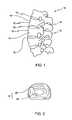
- FIG. 1Depicted in FIG. 1 is a section of a spinal column 10 .
- Spinal column 10comprises a plurality of stacked vertebrae 12 .
- each vertebrae 12iscomprised of a substantially cylindrical vertebral body 14 having a spinous process 16 projecting therefrom.
- Spinal column 10further comprises an intervertebral disc 18 located between each adjacent vertebrae 12 .
- intervertebral disc 18generally consists of an outer ring structure called the annulus fibrosus 20 .
- Annulus Fibrosus 20encircles a gelatinous central core called the nucleus pulposus 22 .
- Intervertebral disc 18is comprised of collagen with annulus fibrosus 20 being significantly stiffer than the gelatinous nucleus pulposus 22 .
- annulus fibrosus 20functions in part as a wall that retains nucleus pulposus 22 .
- Intervertebral disc 18 together with the two adjacent vertebrae 12form a joint motion segment that serves to provide limited motion in forward bending, lateral bending, and rotation.
- Degenerative discs 18can cause debilitating back pain. Discs 18 progressively degenerate during aging, characterized by dehydration and hardening of the nucleus pulposus 22 and the annulus fibrosus 20 .
- the annulus fibrosus 20may weaken and bulge, or may develop fissures that allow the nucleus pulposus 22 to extrude, commonly referred to as disc herniation. This bulging or extrusion often results in a decrease in disc height, thereby putting pressure on nerve roots and/or the spinal cord.
- Various prefabricated prostheseshave been developed to repair or replace a damaged intervertebral disc 18 , including: prostheses for the replacement of the nucleus pulposus, commonly referred to as nucleus replacements; prostheses for the concurrent replacement of the annulus fibrosis, commonly referred to as a total disc replacement; and prostheses in the form of cages filled with osteogenic materials, commonly referred to as interbody fusion devices.
- These prefabricated prosthesesare commercially offered in a limited number of sizes, limiting the surgeon's ability to precisely restore the disc height for individual patients.
- most of these prosthesesrequire the creation of a surgical incision at least large enough to pass the implant to the site of repair. Surgical incisions cause disruptions and damage to various skin, muscle, tendon and ligament structures that extend the time of recover and rehabilitation for patients and that compromise the function of the violated anatomical structures.
- FIG. 1is an elevated side view of a section of a spinal column
- FIG. 2is a top plan view of an intervertebral disc
- FIG. 3is an elevated side view of an in-situ prosthesis formation apparatus
- FIG. 4is an enlarged cross sectional side view of the distal end of the apparatus shown in FIG. 3 ;
- FIG. 5is an enlarged cross sectional side view of an alternative embodiment of the distal end of the apparatus shown in FIG. 3 ;
- FIG. 6is an enlarged cross sectional side view of another alternative embodiment of the distal end of the apparatus shown in FIG. 3 ;
- FIG. 7is an enlarged cross sectional side view of still another alternative embodiment of the distal end of the apparatus shown in FIG. 3 ;
- FIG. 8is a perspective view of a working cannula being positioned at a degenerated intervertebral disc shown in FIG. 2 having a portion of the nucleus pulposus retracted;
- FIG. 9is a perspective view of the apparatus shown in FIG. 3 inserted through the working cannula shown in FIG. 8 so that a balloon of the apparatus resides within the site of the retracted nucleus pulposus;
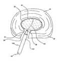
- FIG. 10is a perspective view of the balloon of FIG. 9 being filled with a biomaterial within the site of the retracted nucleus pulposus;
- FIG. 11is a perspective view of the balloon of FIG. 10 being severed for around the biomaterial therein;
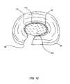
- FIG. 12is a perspective view of the biomaterial of FIG. 11 forming a structural prosthesis within the site of the retracted nucleus pulposus;
- FIG. 13is a partially cut away side view of the balloon of the apparatus shown in FIG. 3 inserted within a vertebral body so as to form a structural prosthesis therein.
- the present inventionrelates to apparatus and methods for the in-situ formation of structural prosthesis.
- such prosthesisare formed so as to replace all or a portion of an intervertebral disc or are formed within a vertebral body so as to reinforce the vertebral body or to restore the height of a compressed vertebral body.
- the apparatus and methodsuse a balloon as a mold.
- the balloonis surgically positioned at the location for the structural prosthesis. Once positioned, the balloon is filled to a predetermined extent with a curable biomaterial.
- the amount of biomaterial material usedcorresponds to the desired size for the structural prosthesis. Once the biomaterial has at least partially cured, the balloon is removed leaving the biomaterial to fully cure into the structural prosthesis.
- Apparatus 30comprises an elongated tubular member 32 having a proximal end 34 and an opposing distal end 36 .
- Tubular member 32has an interior surface 38 bounding a passageway 40 ( FIG. 4 ) longitudinally extending therethrough.
- Tubular member 32can be rigid or flexible and can be made from plastic, metal, or any other material capable sterilization for medical use.
- tubular member 32can comprise a flexible catheter or a rigid cannula.
- Balloon 42Mounted at distal end 36 of tubular member 32 is a balloon 42 .
- Balloon 42has a proximal end 44 and terminates at an opposing distal end 46 .
- Balloon 42is comprised of a boundary wall 48 having an exterior surface 51 and an interior surface 49 . Interior surface 49 bounds a chamber 50 .
- An annular mouth 52is formed at proximal end 44 of balloon 42 and provides fluid communication with chamber 50 . Mouth 52 is coupled in sealed engagement with distal end 36 of tubular member 32 so that passageway 40 of tubular member 32 is in fluid communication with chamber 50 of balloon 42 .
- mouth 52can be coupled with tubular member 32 by welding, adhesive, clamp, or other conventional fastening techniques.
- Balloon 42can also be integrally molded with tubular member 32 so that they form a one-piece member.
- balloon 42is made of a resiliently expandable material. Accordingly, as balloon 42 is filled, it initially inflates to a non-stretched configuration. As balloon 42 is further filled, boundary wall 48 resiliently stretches so as to allow balloon 42 to expand to a larger configuration.
- balloon 42can be made of a flexible static material.
- balloon 42can be comprised of one or two or more sheets of polymeric material that are seamed together. In this embodiment, balloon 42 inflates to a predefined configuration but cannot significantly expand beyond that configuration. By using seamed sheets of static material, balloon 42 can be more easily configured to inflate into any desired configuration.
- Balloon 42is typically made of materials commonly known in the art, such as those used in balloon catheters, balloon angioplasty devices, inflatable cuffs used in endotracheal devices, and balloons used as bone tamps for vertebral body augmentation procedures.
- suitable materials for balloon 42are natural materials or synthetic materials, such as polyurethane, polyolefin, polycarbonate, polyethylene, polyethylene terephtalate, tetrafluoroethylene, or copolymers thereof.
- the material for balloon 42can also be reinforced with fibers or other additives to adjust the strength, flexibility, elasticity, and/or other properties of balloon 42 .
- the additivescan also be used to provide desired shape constraints.
- Suitable materials for fiber reinforcementinclude: carbon fibers, glass fibers, nylon fibers, polyethylene fibers, polyester fibers, and the like.
- balloon 42can be configured to expand into any desired configuration.
- balloon 42is surgically positioned at a location for the structural prosthesis. Once positioned, balloon 42 is selectively filed with a flowable, curable biomaterial.
- the biomaterialis injected into balloon 42 by way of tubular member 32 .
- the biomaterialcan comprise curable hydrogel, polyurethane, calcium phosphate, calcium sulfate, acrylic, carbonate, or any other suitable material that is biocompatible.
- the biomaterialhas a cure time of less than about 30 minutes and preferably less than about 5 minutes.
- meansare provided for at least partially severing boundary wall 48 of balloon 42 after the biomaterial has at least partially cured therein such that balloon 42 can be selectively removed from around the at least partially cured biomaterial.
- a line 60having a proximal end 62 ( FIG. 3 ) and an opposing distal end 64 .
- line 60 or other lines disclosed hereincan be comprised of a metal wire, suture, plastic line, small diameter cord or cable, optical cable, or any other small diameter line.
- line 60extends through passageway 40 of tubular member 32 such that at least a portion of proximal end 62 of line 60 freely projects proximal of tubular member 32 . Furthermore, at least a portion of distal end 64 of line 60 is disposed within balloon 42 . More specifically, distal end 64 of line 60 is embedded within boundary wall 48 of balloon 42 so as to follow a substantially semi-circular path extending from proximal end 44 of balloon 42 , to distal end 46 , and then back toward proximal end 44 on the opposing side of balloon 42 . Line 60 is configured such that when proximal end 62 is pulled, line 60 is pulled out of balloon 42 so as to at least partially sever boundary wall 48 along the track of line 60 .
- tubular member 32is retracted from its surgical placement.
- balloon 42opens along the at least partially severed track of line 60 so that balloon 42 retracts from around the at least partially set biomaterial disposed therein.
- Balloon 42is then fully removed with tubular member 32 , leaving the biomaterial implanted so as to fully cure into the structural prosthesis.
- Line 60can be configured in a variety of different ways to facilitate severing of boundary wall 48 .
- line 60can be embedded within boundary wall 48 such that by simply removing line 60 , boundary wall 48 is sufficiently weakened so that when balloon 42 is pulled on by tubular member 32 , balloon 42 completely severs.
- line 60can be embedded within boundary wall 48 such that line 60 tears boundary wall 48 as line 60 is removed.
- line 60can be made with a sharpened edge, a roughened surface, or sufficiently thin so that line 60 cuts through boundary wall 48 as line 60 is removed.
- a sharpened tooth, hook, spike or other structurecan be placed at one or more locations along line 60 so as to cut boundary wall 48 as line 60 is removed.
- line 60can be configured to efficiently cut both outward and inward.
- line 60can either sever completely through boundary wall 48 or sever a portion of boundary wall 48 sufficiently to weaken it so that boundary wall 48 completely severs as balloon 42 is retracted.
- line 60is shown extending through passageway 40 of tubular member 32 and embedded within boundary wall 48 , in other embodiments, line 60 can extend on the exterior of tubular member 32 .
- line 60can be positioned on exterior surface 51 or interior surface 49 of balloon 42 .
- two or more lines 60can be used to sever boundary wall 48 at different orientations. For example, two lines can extending on opposing sides of balloon 42 and intersect at distal end 46 .
- a support layer 70is applied over line 60 so as to secure line 60 against interior surface 49 of balloon 42 .
- Support layer 70can be applied over all of interior surface 49 or only over the segment along line 60 .
- support layer 70can be applied over exterior surface 51 of balloon 42 so as to secure line 60 against exterior surface 51 .
- Support layer 70can be comprised of an adhesive, tape, or any of the materials of which boundary wall 48 is comprised. Again, as discussed above, multiple lines 60 can be used. Furthermore, any of the different techniques discussed herein can be used for line 60 to facilitate severing of boundary wall 48 .
- FIG. 6Depicted in FIG. 6 is yet another alternative embodiment of the means for at least partially severing boundary wall 48 of balloon 42 .
- a line 76is provided having a proximal end 78 and an opposing distal end 80 .
- Proximal end 78extends out through tubular member 32 while distal end 80 is secured to interior surface 38 of tubular member 32 .
- line 76extends into boundary wall 48 at proximal end 44 of balloon 42 and runs therein to distal end 46 of balloon 42 .
- line 76extends out of boundary wall 48 and then freely passes out through tubular member 32 .
- proximal end 78 of line 42cuts through the inwardly disposed portion of boundary wall 48 .
- distal end 46can also extend out through passageway 40 where it is manually retained.
- two or more lines 76can be used extending from opposing sides of balloon 42 .
- line 76can extend on exterior surface 51 of balloon 42 so as to completely cut through boundary wall 48 when line 76 is removed.
- a looped line 86has a proximal end 88 and an opposing distal end 90 . Starting from proximal end 88 , line 86 extends through passageway 40 and into boundary wall 48 of balloon 42 at proximal end 44 thereof. Line 86 extends embedded with boundary wall 48 to distal end 46 and then back to tubular member 32 . Line 86 then continues out through passageway 40 . Insulation 92 covers lines 86 within passageway 40 .
- an electrical currentis passed through lines 86 so that the non-insulated portion of line 86 embedded within boundary wall 48 functions as a filament that heats up and melts the contacting boundary wall 48 .
- lines 86can be used to sever balloon 42 along different paths.
- line 86can be a conductor of radiofrequency or ultrasound energy, creating localized heating and melting of boundary wall 48 .
- wire 86can comprise a side firing laser that produces localized heating and melting of balloon 42 .
- FIG. 8depicted in FIG. 8 is a intervertebral disc 18 , as previously discussed above with regard to FIGS. 1-2 , in which it is desired to replace the degenerated nucleus pulposus 22 with a structural prosthesis.
- a minimally invasive surgical approachis used to establish a percutaneous tract to the operative site with a guide wire 104 .
- a working cannula 100is then slid over guide wire 104 following which guide wire 104 is removed.
- Microsurgical techniquesare then performed through cannula 100 using endoscopic visualization techniques to form an incision 98 through annulus fibrosus 20 and then substantially remove the degenerated nucleus pulposus 22 therethrough.
- a rupture in annulus fibrosus 20may have already resulted in a substantial loss of nucleus pulposus 22 therethrough.
- distal end 102 of a cannula 100is communication with incision 98 , distal end 36 of tubular member 32 is advanced down through cannula 100 so as to position deflated balloon 42 within the site of the resected nucleus pulposus 22 .
- balloon 42can either freely extend distally of tubular member 32 or can be drawn into passageway 40 of tubular member 32 . If balloon 42 is retained within passageway 40 , a push rod or other structure can be used to push balloon 42 out of passageway and into the site of the resected nucleus pulposus 22 . Alternatively, balloon 42 can be pushed out of tubular member 32 by the injection of biomaterial into tubular member 32 as discussed below.
- the flowable, curable biomaterial 108( FIG. 11 ) is passed down through tubular member 32 and into chamber 50 of balloon 42 .
- Biomaterial 108is injected until balloon 42 inflates and/or expands to the size corresponding to the original nucleus pulposus 22 .
- annulus fibrosus 20functions as a wall that at least partially bounds the expansion of balloon 42 so that the proper amount of biomaterial 108 is injected.
- balloon 42helps to ensure that biomaterial 108 does not leak out through incision 98 or fissures in annulus fibrosus 20 .
- line 60(FIG. 10 ), or other alternatives thereto as discussed above, is used to at least partially sever balloon 42 .
- Tubular member 32is then retracted causing balloon 42 to completely sever, if not previously completely severed, as shown by split 110 .
- Balloon 42is then fully retracted out with tubular member 32 so that severed balloon 42 passes around biomaterial 108 , thereby leaving biomaterial 108 at the site of resected nucleus pulposus 22 .
- biomaterial 108can be allowed to completely cure prior to use of line 60 or removal of balloon 42 .
- tubular member 32is typically bent or otherwise manipulated so as to break the connection of the biomaterial within tubular member 32 to the biomaterial within the site of resected nucleus pulposus 22 .
- the present apparatus and methodscan also be used for a total or substantially total intervertebral disc replacement or for fusing together adjacent vertebrae. That is, microsurgical techniques are performed through cannula 100 to remove nucleus pulposus 22 and either all or a portion of annulus fibrosus 20 .
- balloon 42is then placed as the site of the resected intervertebral disc. Balloon 42 is injected with the biomaterial until it extends to the size of the natural intervertebral disc or portion thereof resected. Once the biomaterial at least partially cures, the line is used to at least partially sever balloon 42 . Tubular member 32 and balloon 42 are then retracted leaving the biomaterial to cure into the final structural prosthesis.
- materials with greater flexibility and compressibilityare preferred, such as a hydrogel or polyurethane.
- materials with greater stiffness and rigidityare preferred, such as calcium phosphate, calcium sulfate, acrylic, and carbonate.
- the present apparatus and methodscan also be used to repair a collapsed or degenerative vertebral body.
- cannula 100is passed through an incision into a vertebral body 14 .
- tubular member 32is passed through cannula 100 so that balloon 42 is disposed within vertebral body 14 .
- Balloon 42is then filled with the biomaterial so that the balloon 42 compress the bone material therein and fills all voids. If vertebral body 14 is collapsed, balloon 42 is filled to the extent necessary to raise vertebral body 14 to its original height. Once balloon 42 is filled to the proper size and the biomaterial is at least partially cured, the line is used to at least partially sever balloon 42 .
- Tubular member 32 and balloon 42are then retracted as discussed above leaving the biomaterial to cure into the final structural prosthesis within vertebral body 14 .
- the inventive apparatus and methodshave a number of benefits.
- balloons 42 and the curable biomaterialcan be implanted through minimally invasive incisions, thereby reducing the risk of infection and decreasing patient recovery time.
- an entire intervertebral disc 18 or portion thereofcan be replaced without the required use of annulus fibrosus 20 or the risk of loss of biomaterial by seepage through fissures.
- the present inventionis depicted herein for use with a spinal column, it is also appreciated that the present invention can be used in other surgical and non-surgical procedures where it is desired to position in-situ a structural member.
Landscapes
- Health & Medical Sciences (AREA)
- Engineering & Computer Science (AREA)
- Orthopedic Medicine & Surgery (AREA)
- Biomedical Technology (AREA)
- Life Sciences & Earth Sciences (AREA)
- Animal Behavior & Ethology (AREA)
- Heart & Thoracic Surgery (AREA)
- General Health & Medical Sciences (AREA)
- Public Health (AREA)
- Veterinary Medicine (AREA)
- Neurology (AREA)
- Transplantation (AREA)
- Vascular Medicine (AREA)
- Surgery (AREA)
- Oral & Maxillofacial Surgery (AREA)
- Cardiology (AREA)
- Molecular Biology (AREA)
- Nuclear Medicine, Radiotherapy & Molecular Imaging (AREA)
- Medical Informatics (AREA)
- Physical Education & Sports Medicine (AREA)
- Prostheses (AREA)
Abstract
Description
Claims (42)
Priority Applications (4)
| Application Number | Priority Date | Filing Date | Title |
|---|---|---|---|
| US10/255,161US6932843B2 (en) | 2002-09-25 | 2002-09-25 | Apparatus and method for the in-situ formation of a structural prosthesis |
| PCT/US2003/023966WO2004028414A1 (en) | 2002-09-25 | 2003-07-31 | Apparatus and method for the in-situ formation of a structural prosthesis |
| EP03798684AEP1549262A4 (en) | 2002-09-25 | 2003-07-31 | APPARATUS AND METHOD FOR THE i IN-SITU /i FORMATION OF A STRUCTURAL PROSTHESIS |
| AU2003254285AAU2003254285A1 (en) | 2002-09-25 | 2003-07-31 | Apparatus and method for the in-situ formation of a structural prosthesis |
Applications Claiming Priority (1)
| Application Number | Priority Date | Filing Date | Title |
|---|---|---|---|
| US10/255,161US6932843B2 (en) | 2002-09-25 | 2002-09-25 | Apparatus and method for the in-situ formation of a structural prosthesis |
Publications (2)
| Publication Number | Publication Date |
|---|---|
| US20040059417A1 US20040059417A1 (en) | 2004-03-25 |
| US6932843B2true US6932843B2 (en) | 2005-08-23 |
Family
ID=31993442
Family Applications (1)
| Application Number | Title | Priority Date | Filing Date |
|---|---|---|---|
| US10/255,161Expired - LifetimeUS6932843B2 (en) | 2002-09-25 | 2002-09-25 | Apparatus and method for the in-situ formation of a structural prosthesis |
Country Status (4)
| Country | Link |
|---|---|
| US (1) | US6932843B2 (en) |
| EP (1) | EP1549262A4 (en) |
| AU (1) | AU2003254285A1 (en) |
| WO (1) | WO2004028414A1 (en) |
Cited By (68)
| Publication number | Priority date | Publication date | Assignee | Title |
|---|---|---|---|---|
| US20050251259A1 (en)* | 2003-07-29 | 2005-11-10 | Loubert Suddaby | Inflatable nuclear prosthesis |
| US20060247784A1 (en)* | 2005-05-02 | 2006-11-02 | Kim Daniel H | Devices, systems and methods for augmenting intervertebral discs |
| US20070005140A1 (en)* | 2005-06-29 | 2007-01-04 | Kim Daniel H | Fabrication and use of biocompatible materials for treating and repairing herniated spinal discs |
| US20070067036A1 (en)* | 2005-09-20 | 2007-03-22 | Zimmer Spine, Inc. | Hydrogel total disc prosthesis |
| US20070073402A1 (en)* | 2005-08-26 | 2007-03-29 | Edward Vresilovic | Hydrogel balloon prosthesis for nucleus pulposus |
| US20070134343A1 (en)* | 2002-11-15 | 2007-06-14 | Trieu Hai H | Collagen-based materials and methods for treating synovial joints |
| US20070233252A1 (en)* | 2006-02-23 | 2007-10-04 | Kim Daniel H | Devices, systems and methods for treating intervertebral discs |
| US20070260315A1 (en)* | 2006-05-03 | 2007-11-08 | Foley Kevin T | Devices and methods for disc height restoration |
| US20070270953A1 (en)* | 2006-03-29 | 2007-11-22 | Sdgi Holdings, Inc. | Transformable spinal implants and methods of use |
| US20080004703A1 (en)* | 2006-06-30 | 2008-01-03 | Warsaw Orthopedic, Inc. | Method of treating a patient using a collagen material |
| US20080004431A1 (en)* | 2006-06-30 | 2008-01-03 | Warsaw Orthopedic Inc | Method of manufacturing an injectable collagen material |
| US20080125782A1 (en)* | 2006-11-29 | 2008-05-29 | Disc Dynamics, Inc. | Method and apparatus for removing an extension from a prosthesis |
| US20080154368A1 (en)* | 2006-12-21 | 2008-06-26 | Warsaw Orthopedic, Inc. | Curable orthopedic implant devices configured to harden after placement in vivo by application of a cure-initiating energy before insertion |
| US20080269717A1 (en)* | 2007-04-30 | 2008-10-30 | Crandall Dennis G | Method of deformity correction in a spine using injectable materials |
| US20090099660A1 (en)* | 2007-10-10 | 2009-04-16 | Warsaw Orthopedic, Inc. | Instrumentation to Facilitate Access into the Intervertebral Disc Space and Introduction of Materials Therein |
| US20100114067A1 (en)* | 2008-10-31 | 2010-05-06 | Warsaw Orthopedic, Inc. | Multi-Chamber Mixing System |
| US7713301B2 (en) | 1994-05-06 | 2010-05-11 | Disc Dynamics, Inc. | Intervertebral disc prosthesis |
| US7713303B2 (en) | 2002-09-18 | 2010-05-11 | Warsaw Orthopedic, Inc. | Collagen-based materials and methods for augmenting intervertebral discs |
| US20100121310A1 (en)* | 2008-11-10 | 2010-05-13 | Warsaw Orthopedic, Inc. | Multiple component mixing and delivery system |
| US7727262B2 (en) | 2000-06-23 | 2010-06-01 | Warsaw Orthopedic, Inc. | Formed in place fixation system with thermal acceleration |
| US7744651B2 (en) | 2002-09-18 | 2010-06-29 | Warsaw Orthopedic, Inc | Compositions and methods for treating intervertebral discs with collagen-based materials |
| US7771478B2 (en) | 2003-04-04 | 2010-08-10 | Theken Spine, Llc | Artificial disc prosthesis |
| US7833249B2 (en) | 2000-06-23 | 2010-11-16 | Warsaw Orthopedic, Inc. | Formable orthopedic fixation system |
| US20110054416A1 (en)* | 2007-09-14 | 2011-03-03 | Hollowell Daniel R | Material control device for inserting material into a targeted anatomical region |
| US20110066244A1 (en)* | 2009-09-11 | 2011-03-17 | William Frasier | Minimally Invasive Intervertebral Staple Distraction Devices |
| US20110066192A1 (en)* | 2009-09-15 | 2011-03-17 | William Frasier | Expandable Ring Intervertebral Fusion Device |
| WO2011075672A1 (en)* | 2009-12-18 | 2011-06-23 | Hollowell Dan R | Apparatus and methods for detaching an expandable member from a medical device |
| US7988735B2 (en)* | 2005-06-15 | 2011-08-02 | Matthew Yurek | Mechanical apparatus and method for delivering materials into the inter-vertebral body space for nucleus replacement |
| US20110213402A1 (en)* | 2005-05-24 | 2011-09-01 | Kyphon Sarl | Low-compliance expandable medical device |
| US8012211B2 (en)* | 2002-11-05 | 2011-09-06 | Spineology, Inc. | Semi-biological intervertebral disc replacement system |
| US8083774B2 (en) | 2000-06-23 | 2011-12-27 | Warsaw Orthopedic, Inc. | Percutaneous vertebral fusion system |
| US8092536B2 (en) | 2006-05-24 | 2012-01-10 | Disc Dynamics, Inc. | Retention structure for in situ formation of an intervertebral prosthesis |
| US8118779B2 (en) | 2006-06-30 | 2012-02-21 | Warsaw Orthopedic, Inc. | Collagen delivery device |
| US8142462B2 (en) | 2004-05-28 | 2012-03-27 | Cavitech, Llc | Instruments and methods for reducing and stabilizing bone fractures |
| US8210729B2 (en) | 2009-04-06 | 2012-07-03 | Illuminoss Medical, Inc. | Attachment system for light-conducting fibers |
| US8221420B2 (en) | 2009-02-16 | 2012-07-17 | Aoi Medical, Inc. | Trauma nail accumulator |
| US8246628B2 (en) | 2006-04-26 | 2012-08-21 | Illuminoss Medical, Inc. | Apparatus for delivery of reinforcing materials to bone |
| US8337556B2 (en) | 2000-06-23 | 2012-12-25 | Sdgi Holdings, Inc. | Curable media for implantable medical device |
| US8348956B2 (en) | 2006-04-26 | 2013-01-08 | Illuminoss Medical, Inc. | Apparatus and methods for reinforcing bone |
| US8353911B2 (en) | 2007-05-21 | 2013-01-15 | Aoi Medical, Inc. | Extendable cutting member |
| US8366711B2 (en) | 2006-11-10 | 2013-02-05 | Illuminoss Medical, Inc. | Systems and methods for internal bone fixation |
| US8399619B2 (en) | 2006-06-30 | 2013-03-19 | Warsaw Orthopedic, Inc. | Injectable collagen material |
| US8403968B2 (en) | 2007-12-26 | 2013-03-26 | Illuminoss Medical, Inc. | Apparatus and methods for repairing craniomaxillofacial bones using customized bone plates |
| US8480718B2 (en) | 2006-12-21 | 2013-07-09 | Warsaw Orthopedic, Inc. | Curable orthopedic implant devices configured to be hardened after placement in vivo |
| US8512338B2 (en) | 2009-04-07 | 2013-08-20 | Illuminoss Medical, Inc. | Photodynamic bone stabilization systems and methods for reinforcing bone |
| US8546456B2 (en) | 2008-07-25 | 2013-10-01 | Smith & Nephew, Inc. | Fracture fixation systems |
| US8663328B2 (en) | 2006-12-21 | 2014-03-04 | Warsaw Orthopedic, Inc. | Methods for positioning a load-bearing component of an orthopedic implant device by inserting a malleable device that hardens in vivo |
| US8684965B2 (en) | 2010-06-21 | 2014-04-01 | Illuminoss Medical, Inc. | Photodynamic bone stabilization and drug delivery systems |
| US8734460B2 (en) | 2006-11-10 | 2014-05-27 | Illuminoss Medical, Inc. | Systems and methods for internal bone fixation |
| US8758407B2 (en) | 2006-12-21 | 2014-06-24 | Warsaw Orthopedic, Inc. | Methods for positioning a load-bearing orthopedic implant device in vivo |
| US8870965B2 (en) | 2009-08-19 | 2014-10-28 | Illuminoss Medical, Inc. | Devices and methods for bone alignment, stabilization and distraction |
| US20140378980A1 (en)* | 2013-06-24 | 2014-12-25 | Roman Lomeli | Cortical Rim-Supporting Interbody Device |
| US8936644B2 (en) | 2011-07-19 | 2015-01-20 | Illuminoss Medical, Inc. | Systems and methods for joint stabilization |
| US8939977B2 (en) | 2012-07-10 | 2015-01-27 | Illuminoss Medical, Inc. | Systems and methods for separating bone fixation devices from introducer |
| US20150094731A1 (en)* | 2013-09-27 | 2015-04-02 | Terumo Kabushiki Kaisha | Bone treatment system |
| US20150094730A1 (en)* | 2013-09-27 | 2015-04-02 | Terumo Kabushiki Kaisha | Bone treatment system |
| US9144442B2 (en) | 2011-07-19 | 2015-09-29 | Illuminoss Medical, Inc. | Photodynamic articular joint implants and methods of use |
| US9179959B2 (en) | 2010-12-22 | 2015-11-10 | Illuminoss Medical, Inc. | Systems and methods for treating conditions and diseases of the spine |
| US9220554B2 (en) | 2010-02-18 | 2015-12-29 | Globus Medical, Inc. | Methods and apparatus for treating vertebral fractures |
| US9427289B2 (en) | 2007-10-31 | 2016-08-30 | Illuminoss Medical, Inc. | Light source |
| US9545321B2 (en) | 2013-03-14 | 2017-01-17 | Spinal Stabilization Technologies Llc | Prosthetic spinal disk nucleus |
| US9687281B2 (en) | 2012-12-20 | 2017-06-27 | Illuminoss Medical, Inc. | Distal tip for bone fixation devices |
| US10314714B2 (en) | 2014-11-04 | 2019-06-11 | Spinal Stabilization Technologies Llc | Percutaneous implantable nuclear prosthesis |
| US10575967B2 (en) | 2015-09-01 | 2020-03-03 | Spinal Stabilization Technologies Llc | Implantable nuclear prosthesis |
| US10806593B2 (en) | 2013-06-24 | 2020-10-20 | DePuy Synthes Products, Inc. | Cortical rim-supporting interbody device |
| US11071572B2 (en) | 2018-06-27 | 2021-07-27 | Illuminoss Medical, Inc. | Systems and methods for bone stabilization and fixation |
| US11633287B2 (en) | 2014-11-04 | 2023-04-25 | Spinal Stabilization Technologies Llc | Percutaneous implantable nuclear prosthesis |
| US11744710B2 (en) | 2018-09-04 | 2023-09-05 | Spinal Stabilization Technologies Llc | Implantable nuclear prosthesis, kits, and related methods |
Families Citing this family (29)
| Publication number | Priority date | Publication date | Assignee | Title |
|---|---|---|---|---|
| US6805695B2 (en) | 2000-04-04 | 2004-10-19 | Spinalabs, Llc | Devices and methods for annular repair of intervertebral discs |
| TW587932B (en)* | 2003-05-21 | 2004-05-21 | Guan-Gu Lin | Removable animal tissue filling device |
| TWI235055B (en)* | 2003-05-21 | 2005-07-01 | Guan-Gu Lin | Filling device capable of removing animal tissues |
| TW200511970A (en)* | 2003-09-29 | 2005-04-01 | Kwan-Ku Lin | A spine wrapping and filling apparatus |
| US8012210B2 (en)* | 2004-01-16 | 2011-09-06 | Warsaw Orthopedic, Inc. | Implant frames for use with settable materials and related methods of use |
| US20060135959A1 (en)* | 2004-03-22 | 2006-06-22 | Disc Dynamics, Inc. | Nuclectomy method and apparatus |
| ES2295723T3 (en)* | 2004-04-22 | 2008-04-16 | Crosstrees Medical, Inc. | EXTRAIBLE DEVICE WITH FILLING TO INSERT A MEDICINAL PRODUCT IN AN ANIMAL FABRIC. |
| JP2008511422A (en)* | 2004-09-02 | 2008-04-17 | クロストゥリーズ・メディカル・インコーポレーテッド | Device and method for distraction of spinal disc space |
| US8702718B2 (en) | 2005-04-29 | 2014-04-22 | Jmea Corporation | Implantation system for tissue repair |
| US7608108B2 (en)* | 2005-04-29 | 2009-10-27 | Jmea Corporation | Tissue repair system |
| US7632313B2 (en)* | 2005-04-29 | 2009-12-15 | Jmea Corporation | Disc repair system |
| US20060253198A1 (en)* | 2005-05-03 | 2006-11-09 | Disc Dynamics, Inc. | Multi-lumen mold for intervertebral prosthesis and method of using same |
| WO2007008794A2 (en)* | 2005-07-07 | 2007-01-18 | Crosstrees Medical, Inc. | Devices and methods for the treatment of bone fracture |
| US7611537B2 (en) | 2005-08-01 | 2009-11-03 | Warsaw Orthopedic, Inc. | System, device, and method for percutaneous interbody device and nucleus removal system |
| US7744630B2 (en)* | 2005-11-15 | 2010-06-29 | Zimmer Spine, Inc. | Facet repair and stabilization |
| EP1956991A1 (en)* | 2005-11-15 | 2008-08-20 | Aoi Medical, Inc. | Inflatable device for restoring anatomy of fractured bone |
| WO2007062394A2 (en)* | 2005-11-23 | 2007-05-31 | Crosstrees Medical, Inc. | Devices and methods for the treatment of bone fracture |
| US20090299476A1 (en)* | 2006-05-19 | 2009-12-03 | Ashish Diwan | Tissue prosthesis |
| US20080114364A1 (en)* | 2006-11-15 | 2008-05-15 | Aoi Medical, Inc. | Tissue cavitation device and method |
| BRPI1015207A2 (en)* | 2009-04-07 | 2016-05-03 | Illuminoss Medical Inc | photodynamic bone stabilization systems and methods for treating spine conditions |
| US8211126B2 (en) | 2009-09-22 | 2012-07-03 | Jmea Corporation | Tissue repair system |
| BR112012011132A2 (en)* | 2009-11-10 | 2016-07-05 | Illuminoss Medical Inc | intramedullary implants having variable fixation placement |
| US9326799B2 (en)* | 2009-12-07 | 2016-05-03 | Globus Medical, Inc. | Methods and apparatus for treating vertebral fractures |
| US11090092B2 (en)* | 2009-12-07 | 2021-08-17 | Globus Medical Inc. | Methods and apparatus for treating vertebral fractures |
| US20130131805A1 (en) | 2010-02-09 | 2013-05-23 | Marc Hendriks | Orthopedic implant |
| US20120130489A1 (en)* | 2010-05-19 | 2012-05-24 | Chernomorsky Ary S | Methods and apparatus for in situ formation of surgical implants |
| US20130261660A1 (en)* | 2012-04-03 | 2013-10-03 | Warsaw Orthopedic, Inc. | Medical devices and methods for inserting an adhesive membrane |
| US20150127104A1 (en)* | 2012-05-03 | 2015-05-07 | ULTIMATE JOINT LTD. a corporation | In-situ formation of a joint replacement prosthesis |
| CN108771563A (en)* | 2018-06-01 | 2018-11-09 | 赵群 | Bone cement antiseep pushing in device |
Citations (22)
| Publication number | Priority date | Publication date | Assignee | Title |
|---|---|---|---|---|
| US3875595A (en) | 1974-04-15 | 1975-04-08 | Edward C Froning | Intervertebral disc prosthesis and instruments for locating same |
| US5002576A (en) | 1988-06-06 | 1991-03-26 | Mecron Medizinische Produkte Gmbh | Intervertebral disk endoprosthesis |
| US5146933A (en)* | 1991-09-20 | 1992-09-15 | Dow Corning Wright Corporation | Implantable prosthetic device and tethered inflation valve for volume |
| US5549679A (en) | 1994-05-20 | 1996-08-27 | Kuslich; Stephen D. | Expandable fabric implant for stabilizing the spinal motion segment |
| US5556429A (en)* | 1994-05-06 | 1996-09-17 | Advanced Bio Surfaces, Inc. | Joint resurfacing system |
| US5645597A (en) | 1995-12-29 | 1997-07-08 | Krapiva; Pavel I. | Disc replacement method and apparatus |
| US5827289A (en) | 1994-01-26 | 1998-10-27 | Reiley; Mark A. | Inflatable device for use in surgical protocols relating to treatment of fractured or diseased bones |
| US5888220A (en)* | 1994-05-06 | 1999-03-30 | Advanced Bio Surfaces, Inc. | Articulating joint repair |
| US6132468A (en) | 1998-09-10 | 2000-10-17 | Mansmann; Kevin A. | Arthroscopic replacement of cartilage using flexible inflatable envelopes |
| US6183518B1 (en) | 1999-02-22 | 2001-02-06 | Anthony C. Ross | Method of replacing nucleus pulposus and repairing the intervertebral disk |
| US6187048B1 (en) | 1994-05-24 | 2001-02-13 | Surgical Dynamics, Inc. | Intervertebral disc implant |
| US6248131B1 (en)* | 1994-05-06 | 2001-06-19 | Advanced Bio Surfaces, Inc. | Articulating joint repair |
| US20010004710A1 (en) | 1994-05-06 | 2001-06-21 | Jeffrey C. Felt | Mold apparatus and kit for in situ tissue repair |
| US6258195B1 (en)* | 1999-03-19 | 2001-07-10 | Scimed Life Systems, Inc. | Multi-cord fusing manufacturing process for catheter members |
| US20010032019A1 (en) | 1999-09-13 | 2001-10-18 | Southwest Research Institute And Keraplast Technol | Implantable prosthetic or tissue expanding device |
| US20020045942A1 (en) | 2000-10-16 | 2002-04-18 | Ham Michael J. | Procedure for repairing damaged discs |
| US20020049498A1 (en) | 2000-10-24 | 2002-04-25 | Yuksel K. Umit | In situ bioprosthetic filler and methods, particularly for the in situ formation of vertebral disc bioprosthetics |
| US20020055757A1 (en)* | 2000-11-03 | 2002-05-09 | Torre Roger De La | Method and device for use in minimally invasive placement of intragastric devices |
| US6395034B1 (en) | 1999-11-24 | 2002-05-28 | Loubert Suddaby | Intervertebral disc prosthesis |
| US6436143B1 (en) | 1999-02-22 | 2002-08-20 | Anthony C. Ross | Method and apparatus for treating intervertebral disks |
| US20020156482A1 (en) | 1994-01-26 | 2002-10-24 | Kyphon Inc. | Expandable preformed structures for deployment in interior body regions |
| US6582446B1 (en)* | 1999-05-06 | 2003-06-24 | J. Alexander Marchosky | Method and apparatus for percutaneous osteoplasty |
- 2002
- 2002-09-25USUS10/255,161patent/US6932843B2/ennot_activeExpired - Lifetime
- 2003
- 2003-07-31EPEP03798684Apatent/EP1549262A4/ennot_activeWithdrawn
- 2003-07-31WOPCT/US2003/023966patent/WO2004028414A1/ennot_activeApplication Discontinuation
- 2003-07-31AUAU2003254285Apatent/AU2003254285A1/ennot_activeAbandoned
Patent Citations (24)
| Publication number | Priority date | Publication date | Assignee | Title |
|---|---|---|---|---|
| US3875595A (en) | 1974-04-15 | 1975-04-08 | Edward C Froning | Intervertebral disc prosthesis and instruments for locating same |
| US5002576A (en) | 1988-06-06 | 1991-03-26 | Mecron Medizinische Produkte Gmbh | Intervertebral disk endoprosthesis |
| US5146933A (en)* | 1991-09-20 | 1992-09-15 | Dow Corning Wright Corporation | Implantable prosthetic device and tethered inflation valve for volume |
| US20020156482A1 (en) | 1994-01-26 | 2002-10-24 | Kyphon Inc. | Expandable preformed structures for deployment in interior body regions |
| US5827289A (en) | 1994-01-26 | 1998-10-27 | Reiley; Mark A. | Inflatable device for use in surgical protocols relating to treatment of fractured or diseased bones |
| US5556429A (en)* | 1994-05-06 | 1996-09-17 | Advanced Bio Surfaces, Inc. | Joint resurfacing system |
| US5888220A (en)* | 1994-05-06 | 1999-03-30 | Advanced Bio Surfaces, Inc. | Articulating joint repair |
| US20010004710A1 (en) | 1994-05-06 | 2001-06-21 | Jeffrey C. Felt | Mold apparatus and kit for in situ tissue repair |
| US6443988B2 (en)* | 1994-05-06 | 2002-09-03 | Disc Dynamics, Inc. | Mold apparatus and kit for in situ tissue repair |
| US6248131B1 (en)* | 1994-05-06 | 2001-06-19 | Advanced Bio Surfaces, Inc. | Articulating joint repair |
| US5571189A (en) | 1994-05-20 | 1996-11-05 | Kuslich; Stephen D. | Expandable fabric implant for stabilizing the spinal motion segment |
| US5549679A (en) | 1994-05-20 | 1996-08-27 | Kuslich; Stephen D. | Expandable fabric implant for stabilizing the spinal motion segment |
| US6187048B1 (en) | 1994-05-24 | 2001-02-13 | Surgical Dynamics, Inc. | Intervertebral disc implant |
| US5645597A (en) | 1995-12-29 | 1997-07-08 | Krapiva; Pavel I. | Disc replacement method and apparatus |
| US6132468A (en) | 1998-09-10 | 2000-10-17 | Mansmann; Kevin A. | Arthroscopic replacement of cartilage using flexible inflatable envelopes |
| US6436143B1 (en) | 1999-02-22 | 2002-08-20 | Anthony C. Ross | Method and apparatus for treating intervertebral disks |
| US6183518B1 (en) | 1999-02-22 | 2001-02-06 | Anthony C. Ross | Method of replacing nucleus pulposus and repairing the intervertebral disk |
| US6258195B1 (en)* | 1999-03-19 | 2001-07-10 | Scimed Life Systems, Inc. | Multi-cord fusing manufacturing process for catheter members |
| US6582446B1 (en)* | 1999-05-06 | 2003-06-24 | J. Alexander Marchosky | Method and apparatus for percutaneous osteoplasty |
| US20010032019A1 (en) | 1999-09-13 | 2001-10-18 | Southwest Research Institute And Keraplast Technol | Implantable prosthetic or tissue expanding device |
| US6395034B1 (en) | 1999-11-24 | 2002-05-28 | Loubert Suddaby | Intervertebral disc prosthesis |
| US20020045942A1 (en) | 2000-10-16 | 2002-04-18 | Ham Michael J. | Procedure for repairing damaged discs |
| US20020049498A1 (en) | 2000-10-24 | 2002-04-25 | Yuksel K. Umit | In situ bioprosthetic filler and methods, particularly for the in situ formation of vertebral disc bioprosthetics |
| US20020055757A1 (en)* | 2000-11-03 | 2002-05-09 | Torre Roger De La | Method and device for use in minimally invasive placement of intragastric devices |
Cited By (131)
| Publication number | Priority date | Publication date | Assignee | Title |
|---|---|---|---|---|
| US7766965B2 (en) | 1994-05-06 | 2010-08-03 | Disc Dynamics, Inc. | Method of making an intervertebral disc prosthesis |
| US7713301B2 (en) | 1994-05-06 | 2010-05-11 | Disc Dynamics, Inc. | Intervertebral disc prosthesis |
| US8337556B2 (en) | 2000-06-23 | 2012-12-25 | Sdgi Holdings, Inc. | Curable media for implantable medical device |
| US8083774B2 (en) | 2000-06-23 | 2011-12-27 | Warsaw Orthopedic, Inc. | Percutaneous vertebral fusion system |
| US7727262B2 (en) | 2000-06-23 | 2010-06-01 | Warsaw Orthopedic, Inc. | Formed in place fixation system with thermal acceleration |
| US7833249B2 (en) | 2000-06-23 | 2010-11-16 | Warsaw Orthopedic, Inc. | Formable orthopedic fixation system |
| US7713303B2 (en) | 2002-09-18 | 2010-05-11 | Warsaw Orthopedic, Inc. | Collagen-based materials and methods for augmenting intervertebral discs |
| US7744651B2 (en) | 2002-09-18 | 2010-06-29 | Warsaw Orthopedic, Inc | Compositions and methods for treating intervertebral discs with collagen-based materials |
| US20120116514A1 (en)* | 2002-11-05 | 2012-05-10 | Kuslich Stephen D | Semi-biological intervertebral disc replacement system |
| US8012211B2 (en)* | 2002-11-05 | 2011-09-06 | Spineology, Inc. | Semi-biological intervertebral disc replacement system |
| US20070134343A1 (en)* | 2002-11-15 | 2007-06-14 | Trieu Hai H | Collagen-based materials and methods for treating synovial joints |
| US7731981B2 (en) | 2002-11-15 | 2010-06-08 | Warsaw Orthopedic, Inc. | Collagen-based materials and methods for treating synovial joints |
| US7771478B2 (en) | 2003-04-04 | 2010-08-10 | Theken Spine, Llc | Artificial disc prosthesis |
| US7597714B2 (en)* | 2003-07-29 | 2009-10-06 | Loubert Suddaby | Inflatable nuclear prosthesis |
| US20050251259A1 (en)* | 2003-07-29 | 2005-11-10 | Loubert Suddaby | Inflatable nuclear prosthesis |
| US8142462B2 (en) | 2004-05-28 | 2012-03-27 | Cavitech, Llc | Instruments and methods for reducing and stabilizing bone fractures |
| US8562634B2 (en) | 2004-05-28 | 2013-10-22 | Cavitech, Llc | Instruments and methods for reducing and stabilizing bone fractures |
| US7857857B2 (en) | 2005-05-02 | 2010-12-28 | The Board Of Trustees Of The Leland Stanford Junior University | Devices, systems and methods for augmenting intervertebral discs |
| US20060247784A1 (en)* | 2005-05-02 | 2006-11-02 | Kim Daniel H | Devices, systems and methods for augmenting intervertebral discs |
| US20060247776A1 (en)* | 2005-05-02 | 2006-11-02 | The Board Of Trustees Of The Leland Stanford Junior University | Systems and methods for augmenting intervertebral discs |
| US20110213402A1 (en)* | 2005-05-24 | 2011-09-01 | Kyphon Sarl | Low-compliance expandable medical device |
| US7988735B2 (en)* | 2005-06-15 | 2011-08-02 | Matthew Yurek | Mechanical apparatus and method for delivering materials into the inter-vertebral body space for nucleus replacement |
| US20070005140A1 (en)* | 2005-06-29 | 2007-01-04 | Kim Daniel H | Fabrication and use of biocompatible materials for treating and repairing herniated spinal discs |
| US20070073402A1 (en)* | 2005-08-26 | 2007-03-29 | Edward Vresilovic | Hydrogel balloon prosthesis for nucleus pulposus |
| US8287595B2 (en)* | 2005-08-26 | 2012-10-16 | Synthes Usa, Llc | Hydrogel balloon prosthesis for nucleus pulposus |
| US20100047437A1 (en)* | 2005-08-26 | 2010-02-25 | Edward Vresilovic | Hydrogel balloon prosthesis for nucleus pulposus |
| US20070067036A1 (en)* | 2005-09-20 | 2007-03-22 | Zimmer Spine, Inc. | Hydrogel total disc prosthesis |
| US20070233252A1 (en)* | 2006-02-23 | 2007-10-04 | Kim Daniel H | Devices, systems and methods for treating intervertebral discs |
| US20070270953A1 (en)* | 2006-03-29 | 2007-11-22 | Sdgi Holdings, Inc. | Transformable spinal implants and methods of use |
| US7993404B2 (en) | 2006-03-29 | 2011-08-09 | Warsaw Orthopedic, Inc. | Transformable spinal implants and methods of use |
| US8348956B2 (en) | 2006-04-26 | 2013-01-08 | Illuminoss Medical, Inc. | Apparatus and methods for reinforcing bone |
| US9265549B2 (en) | 2006-04-26 | 2016-02-23 | Illuminoss Medical, Inc. | Apparatus for delivery of reinforcing materials to bone |
| US10456184B2 (en) | 2006-04-26 | 2019-10-29 | Illuminoss Medical, Inc. | Apparatus for delivery of reinforcing materials to bone |
| US11331132B2 (en) | 2006-04-26 | 2022-05-17 | Illuminoss Medical, Inc. | Apparatus for delivery of reinforcing materials to bone |
| US8668701B2 (en) | 2006-04-26 | 2014-03-11 | Illuminoss Medical, Inc. | Apparatus for delivery of reinforcing materials to bone |
| US9724147B2 (en) | 2006-04-26 | 2017-08-08 | Illuminoss Medical, Inc. | Apparatus for delivery of reinforcing materials to bone |
| US8246628B2 (en) | 2006-04-26 | 2012-08-21 | Illuminoss Medical, Inc. | Apparatus for delivery of reinforcing materials to bone |
| US9254156B2 (en) | 2006-04-26 | 2016-02-09 | Illuminoss Medical, Inc. | Apparatus for delivery of reinforcing materials to bone |
| US20070260315A1 (en)* | 2006-05-03 | 2007-11-08 | Foley Kevin T | Devices and methods for disc height restoration |
| US8092536B2 (en) | 2006-05-24 | 2012-01-10 | Disc Dynamics, Inc. | Retention structure for in situ formation of an intervertebral prosthesis |
| US20080004703A1 (en)* | 2006-06-30 | 2008-01-03 | Warsaw Orthopedic, Inc. | Method of treating a patient using a collagen material |
| US8118779B2 (en) | 2006-06-30 | 2012-02-21 | Warsaw Orthopedic, Inc. | Collagen delivery device |
| US20080004431A1 (en)* | 2006-06-30 | 2008-01-03 | Warsaw Orthopedic Inc | Method of manufacturing an injectable collagen material |
| US8399619B2 (en) | 2006-06-30 | 2013-03-19 | Warsaw Orthopedic, Inc. | Injectable collagen material |
| US12349946B2 (en) | 2006-11-10 | 2025-07-08 | Illuminoss Medical, Inc. | Systems and methods for internal bone fixation |
| US11259847B2 (en) | 2006-11-10 | 2022-03-01 | Illuminoss Medical, Inc. | Systems and methods for internal bone fixation |
| US8906030B2 (en) | 2006-11-10 | 2014-12-09 | Illuminoss Medical, Inc. | Systems and methods for internal bone fixation |
| US9433450B2 (en) | 2006-11-10 | 2016-09-06 | Illuminoss Medical, Inc. | Systems and methods for internal bone fixation |
| US9717542B2 (en) | 2006-11-10 | 2017-08-01 | Illuminoss Medical, Inc. | Systems and methods for internal bone fixation |
| US10543025B2 (en) | 2006-11-10 | 2020-01-28 | Illuminoss Medical, Inc. | Systems and methods for internal bone fixation |
| US8906031B2 (en) | 2006-11-10 | 2014-12-09 | Illuminoss Medical, Inc. | Systems and methods for internal bone fixation |
| US8734460B2 (en) | 2006-11-10 | 2014-05-27 | Illuminoss Medical, Inc. | Systems and methods for internal bone fixation |
| US8366711B2 (en) | 2006-11-10 | 2013-02-05 | Illuminoss Medical, Inc. | Systems and methods for internal bone fixation |
| US11793556B2 (en) | 2006-11-10 | 2023-10-24 | Illuminoss Medical, Inc. | Systems and methods for internal bone fixation |
| US20080125782A1 (en)* | 2006-11-29 | 2008-05-29 | Disc Dynamics, Inc. | Method and apparatus for removing an extension from a prosthesis |
| US8758407B2 (en) | 2006-12-21 | 2014-06-24 | Warsaw Orthopedic, Inc. | Methods for positioning a load-bearing orthopedic implant device in vivo |
| US8480718B2 (en) | 2006-12-21 | 2013-07-09 | Warsaw Orthopedic, Inc. | Curable orthopedic implant devices configured to be hardened after placement in vivo |
| US7771476B2 (en) | 2006-12-21 | 2010-08-10 | Warsaw Orthopedic Inc. | Curable orthopedic implant devices configured to harden after placement in vivo by application of a cure-initiating energy before insertion |
| US8663328B2 (en) | 2006-12-21 | 2014-03-04 | Warsaw Orthopedic, Inc. | Methods for positioning a load-bearing component of an orthopedic implant device by inserting a malleable device that hardens in vivo |
| US20080154368A1 (en)* | 2006-12-21 | 2008-06-26 | Warsaw Orthopedic, Inc. | Curable orthopedic implant devices configured to harden after placement in vivo by application of a cure-initiating energy before insertion |
| US8864801B2 (en) | 2007-04-30 | 2014-10-21 | Warsaw Orthopedic, Inc. | Method of deformity correction in a spine using injectable materials |
| US20080269717A1 (en)* | 2007-04-30 | 2008-10-30 | Crandall Dennis G | Method of deformity correction in a spine using injectable materials |
| US8353911B2 (en) | 2007-05-21 | 2013-01-15 | Aoi Medical, Inc. | Extendable cutting member |
| US8961553B2 (en) | 2007-09-14 | 2015-02-24 | Crosstrees Medical, Inc. | Material control device for inserting material into a targeted anatomical region |
| US20110054416A1 (en)* | 2007-09-14 | 2011-03-03 | Hollowell Daniel R | Material control device for inserting material into a targeted anatomical region |
| US20090099660A1 (en)* | 2007-10-10 | 2009-04-16 | Warsaw Orthopedic, Inc. | Instrumentation to Facilitate Access into the Intervertebral Disc Space and Introduction of Materials Therein |
| US9427289B2 (en) | 2007-10-31 | 2016-08-30 | Illuminoss Medical, Inc. | Light source |
| US8672982B2 (en) | 2007-12-26 | 2014-03-18 | Illuminoss Medical, Inc. | Apparatus and methods for repairing craniomaxillofacial bones using customized bone plates |
| US9005254B2 (en) | 2007-12-26 | 2015-04-14 | Illuminoss Medical, Inc. | Methods for repairing craniomaxillofacial bones using customized bone plate |
| US8403968B2 (en) | 2007-12-26 | 2013-03-26 | Illuminoss Medical, Inc. | Apparatus and methods for repairing craniomaxillofacial bones using customized bone plates |
| US8546456B2 (en) | 2008-07-25 | 2013-10-01 | Smith & Nephew, Inc. | Fracture fixation systems |
| US9730740B2 (en) | 2008-07-25 | 2017-08-15 | Smith & Nephew, Inc. | Fracture fixation systems |
| US20100114067A1 (en)* | 2008-10-31 | 2010-05-06 | Warsaw Orthopedic, Inc. | Multi-Chamber Mixing System |
| US20100121310A1 (en)* | 2008-11-10 | 2010-05-13 | Warsaw Orthopedic, Inc. | Multiple component mixing and delivery system |
| US8128591B2 (en) | 2008-11-10 | 2012-03-06 | Warsaw Orthopedic, Inc. | Multiple component mixing and delivery system |
| US8221420B2 (en) | 2009-02-16 | 2012-07-17 | Aoi Medical, Inc. | Trauma nail accumulator |
| US8328402B2 (en) | 2009-04-06 | 2012-12-11 | Illuminoss Medical, Inc. | Attachment system for light-conducting fibers |
| US8936382B2 (en) | 2009-04-06 | 2015-01-20 | Illuminoss Medical, Inc. | Attachment system for light-conducting fibers |
| US8210729B2 (en) | 2009-04-06 | 2012-07-03 | Illuminoss Medical, Inc. | Attachment system for light-conducting fibers |
| US8574233B2 (en) | 2009-04-07 | 2013-11-05 | Illuminoss Medical, Inc. | Photodynamic bone stabilization systems and methods for reinforcing bone |
| US8512338B2 (en) | 2009-04-07 | 2013-08-20 | Illuminoss Medical, Inc. | Photodynamic bone stabilization systems and methods for reinforcing bone |
| US8870965B2 (en) | 2009-08-19 | 2014-10-28 | Illuminoss Medical, Inc. | Devices and methods for bone alignment, stabilization and distraction |
| US9125706B2 (en) | 2009-08-19 | 2015-09-08 | Illuminoss Medical, Inc. | Devices and methods for bone alignment, stabilization and distraction |
| US8915966B2 (en) | 2009-08-19 | 2014-12-23 | Illuminoss Medical, Inc. | Devices and methods for bone alignment, stabilization and distraction |
| US8685097B2 (en) | 2009-09-11 | 2014-04-01 | DePuy Sunthes Products, LLC. | Minimally invasive intervertebral staple distraction devices |
| US20110066244A1 (en)* | 2009-09-11 | 2011-03-17 | William Frasier | Minimally Invasive Intervertebral Staple Distraction Devices |
| US9216093B2 (en) | 2009-09-11 | 2015-12-22 | DePuy Synthes Products, Inc. | Minimally invasive intervertebral staple distraction devices |
| US9744054B2 (en) | 2009-09-11 | 2017-08-29 | DePuy Synthes Products, Inc. | Minimally invasive intervertebral staple distraction devices |
| US8403988B2 (en) | 2009-09-11 | 2013-03-26 | Depuy Spine, Inc. | Minimally invasive intervertebral staple distraction devices |
| US20110066192A1 (en)* | 2009-09-15 | 2011-03-17 | William Frasier | Expandable Ring Intervertebral Fusion Device |
| US9615933B2 (en) | 2009-09-15 | 2017-04-11 | DePuy Synthes Products, Inc. | Expandable ring intervertebral fusion device |
| WO2011075672A1 (en)* | 2009-12-18 | 2011-06-23 | Hollowell Dan R | Apparatus and methods for detaching an expandable member from a medical device |
| US9220554B2 (en) | 2010-02-18 | 2015-12-29 | Globus Medical, Inc. | Methods and apparatus for treating vertebral fractures |
| US8684965B2 (en) | 2010-06-21 | 2014-04-01 | Illuminoss Medical, Inc. | Photodynamic bone stabilization and drug delivery systems |
| US9855080B2 (en) | 2010-12-22 | 2018-01-02 | Illuminoss Medical, Inc. | Systems and methods for treating conditions and diseases of the spine |
| US10111689B2 (en) | 2010-12-22 | 2018-10-30 | Illuminoss Medical, Inc. | Systems and methods for treating conditions and diseases of the spine |
| US10772664B2 (en) | 2010-12-22 | 2020-09-15 | Illuminoss Medical, Inc. | Systems and methods for treating conditions and diseases of the spine |
| US9179959B2 (en) | 2010-12-22 | 2015-11-10 | Illuminoss Medical, Inc. | Systems and methods for treating conditions and diseases of the spine |
| US8936644B2 (en) | 2011-07-19 | 2015-01-20 | Illuminoss Medical, Inc. | Systems and methods for joint stabilization |
| US9775661B2 (en) | 2011-07-19 | 2017-10-03 | Illuminoss Medical, Inc. | Devices and methods for bone restructure and stabilization |
| US9855145B2 (en) | 2011-07-19 | 2018-01-02 | IlluminsOss Medical, Inc. | Systems and methods for joint stabilization |
| US11559343B2 (en) | 2011-07-19 | 2023-01-24 | Illuminoss Medical, Inc. | Photodynamic articular joint implants and methods of use |
| US11141207B2 (en) | 2011-07-19 | 2021-10-12 | Illuminoss Medical, Inc. | Photodynamic articular joint implants and methods of use |
| US9144442B2 (en) | 2011-07-19 | 2015-09-29 | Illuminoss Medical, Inc. | Photodynamic articular joint implants and methods of use |
| US10292823B2 (en) | 2011-07-19 | 2019-05-21 | Illuminoss Medical, Inc. | Photodynamic articular joint implants and methods of use |
| US9254195B2 (en) | 2011-07-19 | 2016-02-09 | Illuminoss Medical, Inc. | Systems and methods for joint stabilization |
| US8939977B2 (en) | 2012-07-10 | 2015-01-27 | Illuminoss Medical, Inc. | Systems and methods for separating bone fixation devices from introducer |
| US10575882B2 (en) | 2012-12-20 | 2020-03-03 | Illuminoss Medical, Inc. | Distal tip for bone fixation devices |
| US9687281B2 (en) | 2012-12-20 | 2017-06-27 | Illuminoss Medical, Inc. | Distal tip for bone fixation devices |
| US12364521B2 (en) | 2012-12-20 | 2025-07-22 | Illuminoss Medical, Inc. | Distal tip for bone fixation devices |
| US11406513B2 (en) | 2013-03-14 | 2022-08-09 | Spinal Stabilization Technologies, Llc | Prosthetic spinal disk nucleus |
| US9545321B2 (en) | 2013-03-14 | 2017-01-17 | Spinal Stabilization Technologies Llc | Prosthetic spinal disk nucleus |
| US20140378980A1 (en)* | 2013-06-24 | 2014-12-25 | Roman Lomeli | Cortical Rim-Supporting Interbody Device |
| US12035954B2 (en)* | 2013-06-24 | 2024-07-16 | DePuy Synthes Products, Inc. | Cortical rim-supporting interbody device |
| US10758288B2 (en)* | 2013-06-24 | 2020-09-01 | DePuy Synthes Products, Inc. | Cortical rim-supporting interbody device |
| US10806593B2 (en) | 2013-06-24 | 2020-10-20 | DePuy Synthes Products, Inc. | Cortical rim-supporting interbody device |
| US20200352616A1 (en)* | 2013-06-24 | 2020-11-12 | DePuy Synthes Products, Inc. | Cortical Rim-Supporting Interbody Device |
| US20180271576A1 (en)* | 2013-06-24 | 2018-09-27 | DePuy Synthes Products, Inc. | Cortical Rim-Supporting Interbody Device |
| US20150094731A1 (en)* | 2013-09-27 | 2015-04-02 | Terumo Kabushiki Kaisha | Bone treatment system |
| US20150094730A1 (en)* | 2013-09-27 | 2015-04-02 | Terumo Kabushiki Kaisha | Bone treatment system |
| US9877762B2 (en)* | 2013-09-27 | 2018-01-30 | Terumo Kabushiki Kaisha | Bone treatment system |
| US11633287B2 (en) | 2014-11-04 | 2023-04-25 | Spinal Stabilization Technologies Llc | Percutaneous implantable nuclear prosthesis |
| US11638649B2 (en) | 2014-11-04 | 2023-05-02 | Spinal Stabilization Technologies Llc | Percutaneous implantable nuclear prosthesis |
| US12279963B2 (en) | 2014-11-04 | 2025-04-22 | Spinal Stabilization Technologies Llc | Percutaneous implantable nuclear prosthesis |
| US10314714B2 (en) | 2014-11-04 | 2019-06-11 | Spinal Stabilization Technologies Llc | Percutaneous implantable nuclear prosthesis |
| US11576793B2 (en) | 2015-09-01 | 2023-02-14 | Spinal Stabilization Technologies Llc | Implantable nuclear prosthesis |
| US10575967B2 (en) | 2015-09-01 | 2020-03-03 | Spinal Stabilization Technologies Llc | Implantable nuclear prosthesis |
| US11419649B2 (en) | 2018-06-27 | 2022-08-23 | Illuminoss Medical, Inc. | Systems and methods for bone stabilization and fixation |
| US11071572B2 (en) | 2018-06-27 | 2021-07-27 | Illuminoss Medical, Inc. | Systems and methods for bone stabilization and fixation |
| US12161373B2 (en) | 2018-06-27 | 2024-12-10 | Illuminoss Medical, Inc. | Systems and methods for bone stabilization and fixation |
| US11744710B2 (en) | 2018-09-04 | 2023-09-05 | Spinal Stabilization Technologies Llc | Implantable nuclear prosthesis, kits, and related methods |
Also Published As
| Publication number | Publication date |
|---|---|
| EP1549262A1 (en) | 2005-07-06 |
| EP1549262A4 (en) | 2009-07-22 |
| US20040059417A1 (en) | 2004-03-25 |
| WO2004028414A1 (en) | 2004-04-08 |
| AU2003254285A1 (en) | 2004-04-19 |
Similar Documents
| Publication | Publication Date | Title |
|---|---|---|
| US6932843B2 (en) | Apparatus and method for the in-situ formation of a structural prosthesis | |
| KR100609651B1 (en) | Instrument of Spinal Disc Reinforcement | |
| US6899716B2 (en) | Method and apparatus for spinal augmentation | |
| US7727263B2 (en) | Articulating spinal implant | |
| US7014633B2 (en) | Methods of performing procedures in the spine | |
| US7608077B2 (en) | Method and apparatus for spinal distraction and fusion | |
| US20070021835A1 (en) | Systems and methods for providing prostheses | |
| JP4456002B2 (en) | Method and device for intervertebral disc expansion | |
| US20090054990A1 (en) | Multi-lumen mold for intervertebral prosthesis and method of using same | |
| US20080086133A1 (en) | Expandable porous mesh bag device and methods of use for reduction, filling, fixation and supporting of bone | |
| US20030195518A1 (en) | Methods and apparatus for performing therapeutic procedures in the spine | |
| MXPA03003600A (en) | Devices and method for nucleus pulposus augmentation and retention. | |
| JP2008541939A (en) | Internal resection prosthesis | |
| KR102130333B1 (en) | Medical Device for repairing and preventing recurrence of herniated disc | |
| US8709084B2 (en) | Devices for delivering spinal disc implants |
Legal Events
| Date | Code | Title | Description |
|---|---|---|---|
| AS | Assignment | Owner name:MEDICINELODGE, INC., UTAH Free format text:ASSIGNMENT OF ASSIGNORS INTEREST;ASSIGNORS:SMITH, STEPHEN A.;FALLIN, T. WADE;REEL/FRAME:013479/0584 Effective date:20021010 | |
| STCF | Information on status: patent grant | Free format text:PATENTED CASE | |
| CC | Certificate of correction | ||
| AS | Assignment | Owner name:SANKATY ADVISORS, LLC,MASSACHUSETTS Free format text:SECURITY AGREEMENT;ASSIGNOR:MEDICINELODGE, INC.;REEL/FRAME:018720/0476 Effective date:20070102 Owner name:SANKATY ADVISORS, LLC, MASSACHUSETTS Free format text:SECURITY AGREEMENT;ASSIGNOR:MEDICINELODGE, INC.;REEL/FRAME:018720/0476 Effective date:20070102 | |
| FPAY | Fee payment | Year of fee payment:4 | |
| AS | Assignment | Owner name:MEDICINELODGE HOLDINGS CORP., TEXAS Free format text:TERMINATION AND RELEASE OF SECURITY INTEREST;ASSIGNOR:SANKATY ADVISORS, LLC, AS ADMINISTRATIVE AGENT;REEL/FRAME:028157/0648 Effective date:20120502 Owner name:MEDICINELODGE, INC., TEXAS Free format text:TERMINATION AND RELEASE OF SECURITY INTEREST;ASSIGNOR:SANKATY ADVISORS, LLC, AS ADMINISTRATIVE AGENT;REEL/FRAME:028157/0648 Effective date:20120502 Owner name:PNC BANK, NATIONAL ASSOCIATION, AS AGENT, NEW JERS Free format text:SECURITY AGREEMENT;ASSIGNORS:IMDS CORPORATION;FRONTIER BIOMEDICAL, LLC;REEL/FRAME:028157/0389 Effective date:20120502 | |
| REMI | Maintenance fee reminder mailed | ||
| FPAY | Fee payment | Year of fee payment:8 | |
| SULP | Surcharge for late payment | Year of fee payment:7 | |
| AS | Assignment | Owner name:FRONTIER BIOMEDICAL, LLC, UTAH Free format text:RELEASE BY SECURED PARTY;ASSIGNOR:PNC BANK;REEL/FRAME:031174/0714 Effective date:20130830 Owner name:IMDS CORPORATION, UTAH Free format text:RELEASE BY SECURED PARTY;ASSIGNOR:PNC BANK;REEL/FRAME:031174/0714 Effective date:20130830 | |
| AS | Assignment | Owner name:IMDS CORPORATION, TEXAS Free format text:RELEASE BY SECURED PARTY;ASSIGNOR:PNC BANK, NATIONAL ASSOCIATION, AS AGENT;REEL/FRAME:037163/0367 Effective date:20151127 | |
| FPAY | Fee payment | Year of fee payment:12 |