US6932833B1 - Method and barrier for limiting fluid movement through a tissue rent - Google Patents
Method and barrier for limiting fluid movement through a tissue rentDownload PDFInfo
- Publication number
- US6932833B1 US6932833B1US10/114,662US11466202AUS6932833B1US 6932833 B1US6932833 B1US 6932833B1US 11466202 AUS11466202 AUS 11466202AUS 6932833 B1US6932833 B1US 6932833B1
- Authority
- US
- United States
- Prior art keywords
- rent
- plug
- swellable
- site
- parts
- Prior art date
- Legal status (The legal status is an assumption and is not a legal conclusion. Google has not performed a legal analysis and makes no representation as to the accuracy of the status listed.)
- Expired - Fee Related, expires
Links
- 238000000034methodMethods0.000titleclaimsabstractdescription53
- 239000012530fluidSubstances0.000titleclaimsabstractdescription16
- 230000004888barrier functionEffects0.000titleabstractdescription53
- 210000001951dura materAnatomy0.000claimsdescription13
- 230000007547defectEffects0.000claimsdescription10
- 210000002330subarachnoid spaceAnatomy0.000claimsdescription9
- 239000000523sampleSubstances0.000claimsdescription6
- 238000007917intracranial administrationMethods0.000claimsdescription5
- 230000037361pathwayEffects0.000claims8
- 239000000463materialSubstances0.000abstractdescription54
- 239000012528membraneSubstances0.000abstractdescription41
- 238000011065in-situ storageMethods0.000abstractdescription9
- 230000035876healingEffects0.000abstractdescription3
- 239000011324beadSubstances0.000description48
- 210000004379membraneAnatomy0.000description40
- 208000005538Post-Dural Puncture HeadacheDiseases0.000description27
- 210000001175cerebrospinal fluidAnatomy0.000description21
- 241001269524DuraSpecies0.000description15
- 230000008961swellingEffects0.000description12
- 210000001519tissueAnatomy0.000description11
- 238000007913intrathecal administrationMethods0.000description10
- 210000004369bloodAnatomy0.000description9
- 239000008280bloodSubstances0.000description9
- 238000007726management methodMethods0.000description8
- 230000015572biosynthetic processEffects0.000description6
- 206010052904Musculoskeletal stiffnessDiseases0.000description5
- 208000002193PainDiseases0.000description5
- 230000036407painEffects0.000description5
- 210000003446pia materAnatomy0.000description5
- 210000000278spinal cordAnatomy0.000description5
- 102000008186CollagenHuman genes0.000description4
- 108010035532CollagenProteins0.000description4
- 108010010803GelatinProteins0.000description4
- 206010019233HeadachesDiseases0.000description4
- 229920003171Poly (ethylene oxide)Polymers0.000description4
- 210000000576arachnoidAnatomy0.000description4
- 229920001436collagenPolymers0.000description4
- 229920000159gelatinPolymers0.000description4
- 235000019322gelatineNutrition0.000description4
- 235000011852gelatine dessertsNutrition0.000description4
- 231100000869headacheToxicity0.000description4
- 238000003780insertionMethods0.000description4
- 230000037431insertionEffects0.000description4
- -1poly(vinyl alcohol)Polymers0.000description4
- 229920000642polymerPolymers0.000description4
- 229920002451polyvinyl alcoholPolymers0.000description4
- KIUKXJAPPMFGSW-DNGZLQJQSA-N(2S,3S,4S,5R,6R)-6-[(2S,3R,4R,5S,6R)-3-Acetamido-2-[(2S,3S,4R,5R,6R)-6-[(2R,3R,4R,5S,6R)-3-acetamido-2,5-dihydroxy-6-(hydroxymethyl)oxan-4-yl]oxy-2-carboxy-4,5-dihydroxyoxan-3-yl]oxy-5-hydroxy-6-(hydroxymethyl)oxan-4-yl]oxy-3,4,5-trihydroxyoxane-2-carboxylic acidChemical compoundCC(=O)N[C@H]1[C@H](O)O[C@H](CO)[C@@H](O)[C@@H]1O[C@H]1[C@H](O)[C@@H](O)[C@H](O[C@H]2[C@@H]([C@@H](O[C@H]3[C@@H]([C@@H](O)[C@H](O)[C@H](O3)C(O)=O)O)[C@H](O)[C@@H](CO)O2)NC(C)=O)[C@@H](C(O)=O)O1KIUKXJAPPMFGSW-DNGZLQJQSA-N0.000description3
- 230000003444anaesthetic effectEffects0.000description3
- 239000012736aqueous mediumSubstances0.000description3
- 239000003814drugSubstances0.000description3
- 239000008273gelatinSubstances0.000description3
- 229920002674hyaluronanPolymers0.000description3
- 229960003160hyaluronic acidDrugs0.000description3
- 210000002784stomachAnatomy0.000description3
- 208000024891symptomDiseases0.000description3
- 238000002560therapeutic procedureMethods0.000description3
- 230000002792vascularEffects0.000description3
- 229920000936AgarosePolymers0.000description2
- 241000124008MammaliaSpecies0.000description2
- 239000002251absorbable suture materialSubstances0.000description2
- 229940035676analgesicsDrugs0.000description2
- 239000000730antalgic agentSubstances0.000description2
- 238000013459approachMethods0.000description2
- 210000004556brainAnatomy0.000description2
- RYYVLZVUVIJVGH-UHFFFAOYSA-NcaffeineChemical compoundCN1C(=O)N(C)C(=O)C2=C1N=CN2CRYYVLZVUVIJVGH-UHFFFAOYSA-N0.000description2
- 229920002678cellulosePolymers0.000description2
- 235000010980celluloseNutrition0.000description2
- 239000000470constituentSubstances0.000description2
- 210000003792cranial nerveAnatomy0.000description2
- 239000007857degradation productSubstances0.000description2
- 230000018044dehydrationEffects0.000description2
- 238000006297dehydration reactionMethods0.000description2
- 238000003745diagnosisMethods0.000description2
- 239000000499gelSubstances0.000description2
- 230000036541healthEffects0.000description2
- 210000004749ligamentum flavumAnatomy0.000description2
- 238000009608myelographyMethods0.000description2
- 229920002463poly(p-dioxanone) polymerPolymers0.000description2
- 239000000622polydioxanoneSubstances0.000description2
- 238000002360preparation methodMethods0.000description2
- 230000004044responseEffects0.000description2
- 239000000126substanceSubstances0.000description2
- 238000001356surgical procedureMethods0.000description2
- 229920001059synthetic polymerPolymers0.000description2
- ZFXYFBGIUFBOJW-UHFFFAOYSA-NtheophyllineChemical compoundO=C1N(C)C(=O)N(C)C2=C1NC=N2ZFXYFBGIUFBOJW-UHFFFAOYSA-N0.000description2
- 238000011282treatmentMethods0.000description2
- 210000003932urinary bladderAnatomy0.000description2
- XLYOFNOQVPJJNP-UHFFFAOYSA-NwaterSubstancesOXLYOFNOQVPJJNP-UHFFFAOYSA-N0.000description2
- WWIKWOJUJQCHIZ-UHFFFAOYSA-N1-methyl-9h-xantheneChemical classO1C2=CC=CC=C2CC2=C1C=CC=C2CWWIKWOJUJQCHIZ-UHFFFAOYSA-N0.000description1
- 208000024827Alzheimer diseaseDiseases0.000description1
- 201000004569BlindnessDiseases0.000description1
- 241000283690Bos taurusSpecies0.000description1
- 206010018985Haemorrhage intracranialDiseases0.000description1
- 208000008574Intracranial HemorrhagesDiseases0.000description1
- LPHGQDQBBGAPDZ-UHFFFAOYSA-NIsocaffeineNatural productsCN1C(=O)N(C)C(=O)C2=C1N(C)C=N2LPHGQDQBBGAPDZ-UHFFFAOYSA-N0.000description1
- 201000009906MeningitisDiseases0.000description1
- 206010053156Musculoskeletal discomfortDiseases0.000description1
- 206010033799ParalysisDiseases0.000description1
- 102000029797PrionHuman genes0.000description1
- 108091000054PrionProteins0.000description1
- 208000002667Subdural HematomaDiseases0.000description1
- 208000009205TinnitusDiseases0.000description1
- 208000012886VertigoDiseases0.000description1
- 241000700605VirusesSpecies0.000description1
- 206010047571Visual impairmentDiseases0.000description1
- 206010047700VomitingDiseases0.000description1
- 206010000269abscessDiseases0.000description1
- 238000010521absorption reactionMethods0.000description1
- 239000000654additiveSubstances0.000description1
- 230000000996additive effectEffects0.000description1
- 210000000577adipose tissueAnatomy0.000description1
- 230000002411adverseEffects0.000description1
- 206010002026amyotrophic lateral sclerosisDiseases0.000description1
- 238000004458analytical methodMethods0.000description1
- 229940035674anestheticsDrugs0.000description1
- 230000003474anti-emetic effectEffects0.000description1
- 239000002111antiemetic agentSubstances0.000description1
- 229940125683antiemetic agentDrugs0.000description1
- 239000004599antimicrobialSubstances0.000description1
- 210000000709aortaAnatomy0.000description1
- 206010003074arachnoiditisDiseases0.000description1
- 230000008499blood brain barrier functionEffects0.000description1
- 210000001218blood-brain barrierAnatomy0.000description1
- 230000036760body temperatureEffects0.000description1
- 238000013276bronchoscopyMethods0.000description1
- 229960001948caffeineDrugs0.000description1
- VJEONQKOZGKCAK-UHFFFAOYSA-NcaffeineNatural productsCN1C(=O)N(C)C(=O)C2=C1C=CN2CVJEONQKOZGKCAK-UHFFFAOYSA-N0.000description1
- 150000001720carbohydratesChemical class0.000description1
- 230000015556catabolic processEffects0.000description1
- 230000005779cell damageEffects0.000description1
- 230000030833cell deathEffects0.000description1
- 208000037887cell injuryDiseases0.000description1
- 230000001413cellular effectEffects0.000description1
- 230000033077cellular processEffects0.000description1
- 239000001913celluloseSubstances0.000description1
- 210000003169central nervous systemAnatomy0.000description1
- 230000002490cerebral effectEffects0.000description1
- 239000003795chemical substances by applicationSubstances0.000description1
- 238000002512chemotherapyMethods0.000description1
- 239000002872contrast mediaSubstances0.000description1
- 238000012937correctionMethods0.000description1
- 230000002380cytological effectEffects0.000description1
- 238000011257definitive treatmentMethods0.000description1
- 230000003412degenerative effectEffects0.000description1
- 238000006731degradation reactionMethods0.000description1
- 230000003292diminished effectEffects0.000description1
- 201000010099diseaseDiseases0.000description1
- 208000037265diseases, disorders, signs and symptomsDiseases0.000description1
- 238000004090dissolutionMethods0.000description1
- 229940079593drugDrugs0.000description1
- 230000000694effectsEffects0.000description1
- 238000001839endoscopyMethods0.000description1
- 230000006862enzymatic digestionEffects0.000description1
- 239000000835fiberSubstances0.000description1
- 210000002532foramen magnumAnatomy0.000description1
- ZZUFCTLCJUWOSV-UHFFFAOYSA-NfurosemideChemical compoundC1=C(Cl)C(S(=O)(=O)N)=CC(C(O)=O)=C1NCC1=CC=CO1ZZUFCTLCJUWOSV-UHFFFAOYSA-N0.000description1
- 210000001035gastrointestinal tractAnatomy0.000description1
- 239000003193general anesthetic agentSubstances0.000description1
- 239000000017hydrogelSubstances0.000description1
- 239000012678infectious agentSubstances0.000description1
- 230000028709inflammatory responseEffects0.000description1
- 239000007924injectionSubstances0.000description1
- 238000002347injectionMethods0.000description1
- 229910052500inorganic mineralInorganic materials0.000description1
- 238000007689inspectionMethods0.000description1
- 238000002357laparoscopic surgeryMethods0.000description1
- 201000010901lateral sclerosisDiseases0.000description1
- 210000000265leukocyteAnatomy0.000description1
- 230000005923long-lasting effectEffects0.000description1
- 238000009593lumbar punctureMethods0.000description1
- 210000004705lumbosacral regionAnatomy0.000description1
- 230000001926lymphatic effectEffects0.000description1
- 206010025382macrocytosisDiseases0.000description1
- 210000002540macrophageAnatomy0.000description1
- 238000012423maintenanceMethods0.000description1
- 230000003211malignant effectEffects0.000description1
- 210000005171mammalian brainAnatomy0.000description1
- 238000004519manufacturing processMethods0.000description1
- 230000007246mechanismEffects0.000description1
- 239000002207metaboliteSubstances0.000description1
- 230000005012migrationEffects0.000description1
- 238000013508migrationMethods0.000description1
- 239000011707mineralSubstances0.000description1
- 238000002324minimally invasive surgeryMethods0.000description1
- 230000000116mitigating effectEffects0.000description1
- 208000005264motor neuron diseaseDiseases0.000description1
- 201000006417multiple sclerosisDiseases0.000description1
- 210000000056organAnatomy0.000description1
- 230000000399orthopedic effectEffects0.000description1
- 208000021090palsyDiseases0.000description1
- 230000008506pathogenesisEffects0.000description1
- 210000003200peritoneal cavityAnatomy0.000description1
- 239000002504physiological saline solutionSubstances0.000description1
- 230000002980postoperative effectEffects0.000description1
- 108090000623proteins and genesProteins0.000description1
- 102000004169proteins and genesHuman genes0.000description1
- 238000000926separation methodMethods0.000description1
- 238000004513sizingMethods0.000description1
- 210000003625skullAnatomy0.000description1
- 238000002693spinal anesthesiaMethods0.000description1
- 238000007920subcutaneous administrationMethods0.000description1
- 238000009120supportive therapyMethods0.000description1
- 239000003356suture materialSubstances0.000description1
- 208000011580syndromic diseaseDiseases0.000description1
- 229960000278theophyllineDrugs0.000description1
- 229940124597therapeutic agentDrugs0.000description1
- 210000000115thoracic cavityAnatomy0.000description1
- 231100000886tinnitusToxicity0.000description1
- 230000009466transformationEffects0.000description1
- 230000007704transitionEffects0.000description1
- 238000009966trimmingMethods0.000description1
- 210000002700urineAnatomy0.000description1
- 231100000889vertigoToxicity0.000description1
- 230000000007visual effectEffects0.000description1
Images


Classifications
- A—HUMAN NECESSITIES
- A61—MEDICAL OR VETERINARY SCIENCE; HYGIENE
- A61B—DIAGNOSIS; SURGERY; IDENTIFICATION
- A61B17/00—Surgical instruments, devices or methods
- A61B17/0057—Implements for plugging an opening in the wall of a hollow or tubular organ, e.g. for sealing a vessel puncture or closing a cardiac septal defect
- A—HUMAN NECESSITIES
- A61—MEDICAL OR VETERINARY SCIENCE; HYGIENE
- A61B—DIAGNOSIS; SURGERY; IDENTIFICATION
- A61B17/00—Surgical instruments, devices or methods
- A61B2017/00831—Material properties
- A61B2017/00898—Material properties expandable upon contact with fluid
- A—HUMAN NECESSITIES
- A61—MEDICAL OR VETERINARY SCIENCE; HYGIENE
- A61B—DIAGNOSIS; SURGERY; IDENTIFICATION
- A61B17/00—Surgical instruments, devices or methods
- A61B17/12—Surgical instruments, devices or methods for ligaturing or otherwise compressing tubular parts of the body, e.g. blood vessels or umbilical cord
- A61B17/12022—Occluding by internal devices, e.g. balloons or releasable wires
- A61B2017/1205—Introduction devices
Definitions
- This inventionrelates to limiting fluid movement through rents in body tissues, and particularly the invention relates to providing a barrier for fluid movement through a puncture in a membranous tissue such as the dura mater.
- the mammalian brain and spinal cordare closely invested by a membrane termed the pia mater, and are surrounded by a thick inelastic membrane termed the dura mater.
- a delicate membrane termed the arachnoidenvelops the brain and spinal cord between the dura mater and the pia mater.
- the arachnoidis separated from the pia mater by the so-called intrathecal or subarachnoid space, which is filled with cerebrospinal fluid (“CSF”).
- CSFcerebrospinal fluid
- the intrathecal spaceis accessed clinically, usually by a percutaneous needle puncture through the dura, for a wide variety of purposes, including collection of CSF for chemical and cytological analysis and delivery of therapeutic agents.
- Percutaneous needle puncture through the durais one of the most common procedures performed in clinical medicine.
- Intraspinal administration of anesthetics and analgesicshas been performed for over one hundred years; it has in recent years come into increasing use in obstetrics, urology, and orthopedics, and it is now a mainstay of therapy in the rapidly growing field of pain management.
- Diagnostic myelographyis commonly employed prior to all types of spinal surgery, entailing injection of radiographic contrast material into the intrathecal space.
- the intrathecal spacealso provides a depot for administration of chemotherapy, and rapid advances in neurobiology promise a range of new therapies directed at degenerative central nervous system conditions.
- Diseasessuch as multiple sclerosis, amyelotrophic lateral sclerosis (Lou Gehrig's disease), Alzheimer's disease, and others, will likely generate increased need for intrathecal access to permit delivery of drugs that may not easily cross the blood-brain barrier.
- Headacheis the most common complication of dural puncture.
- the pathogenesis of post dural puncture headache (PDPH)is generally believed to be related to ongoing CSF leak at the site of the dural puncture, although the mechanism of pain is not clear.
- Low CSF pressuremay result in traction on pain sensitive structures, especially where the subject is in the upright position, caused by loss of the cushioning effect of the normal CSF volume.
- Vascular dilatation in response to low CSF volumemay also be a factor, and neurohumeral responses have been implicated as well.
- the reported incidence of PDPHranges from two percent to 75 percent, depending on a variety of epidemiological factors, including the age, gender, and medical condition of the patient. Women are more likely than men to suffer PDPH, and the rate of PDPH is more likely in younger than in older adults; and it is therefore unsurprising that PDPH is a significant problem following spinal anesthesia in the obstetrical population.
- PDPH pain due to PDPHis typically severe and long-lasting, and it can be completely disabling in some instances for days to weeks following the dural puncture procedure.
- PDPH paincan be relieved by maintaining the subject in a supine position, and patients often are confined to bed for the duration of the headache episode.
- Symptoms associated with PDPHinclude nausea and vomiting which predisposes the patient to dehydration and impairs the patient's ability to replace lost CSF, prolonging the painful syndrome.
- Visual disturbances, tinnitus, vertigo, neck stiffness and auditory symptomsall contribute to the disability associated with PDPH. Severe traction on cranial nerves resulting from low CSF pressure can cause significant palsy, particularly of the with cranial nerve.
- Nonspecific, supportive therapiesincluding correction of dehydration and administration of analgesics and anti-emetics are generally sufficient for mild PDPH, in conjunction with maintenance of a supine position at bed rest.
- Corrective therapiesinclude treatments designed to increase CSF volume and obtund the neurohumeral or vascular cause of the headache.
- Methylxanthenessuch as caffeine and theophylline can constrict cerebral venous channels and promote CSF production, and such agents are often sufficient to control mild cases of PDPH.
- the definitive treatment for PDPHis to stop the leak by performing an epidural blood patch.
- the blood patchhalts the flow of CSF from the intrathecal space, reversing the pressure gradient from lumbar spine to cranial vault, and pushes the remaining CSF toward the brain to provide support for the intracranial structures, thereby producing immediate relief.
- the success rate of the dural blood patch in mitigating PDPHis reported as 85–95 percent.
- PDPHcontinues to be a very troublesome complication of otherwise successful intrathecal access by dural puncture, which may have important implications for the patient's post-operative course. For instance, PDPH following cesarean section results in poorer maternal-infant bonding and inability to breast-feed. Diagnostic lumbar puncture is frequently performed for diagnosis of headache, for example to rule out meningitis, and the presence of PDPH may seriously confound efforts and diagnosis. PDPH is very costly in terms of lost days at work and diminished productivity, and additional days of hospitalization, economically burdening the patient and the employer as well as the health care and health insurance systems.
- the inventionprovides for limiting fluid movement through a rent in a membranous tissue by forming a biocompatible and biodegradable barrier at the site of the rent.
- the barrieris formed by inserting into the rent a plug that includes connected water-swellable parts, so that the swellable parts expand in situ to form the barrier and occlude the rent.
- the inventioncan be employed in connection with any of the many procedures in which access to an internal body space is made by way of a puncture in a wall or membrane. Particularly, for example, the invention can be employed prophylactically at the conclusion of a conventional dural access procedure.
- the materials of which the plug is madeare biocompatible. Generally, as deployed according to the invention, the plug materials do not cause significant cell injury or death; they do not cause an adverse inflammatory response; and they do not cause malignant cellular transformation.
- the materials of which the plug is madeare biodegradable.
- the plug materialsare capable of being broken down and removed from the site by normal physiologic and cellular processes within the body of the subject being treated, typically including for example dissolution in the aqueous environment, leukocyte/macrophage macrocytosis, and enzymatic digestion.
- the degradation productsare metabolized or transferred away from the site ultimately through venous and lymphatic channels.
- the degradation products and their metabolitesare also biocompatible.
- the plug or barrier materialsdo not persist permanently at the site, and degradation and removal of residues of the material proceeds to completion over a course of time of weeks or months.
- Plugs according to inventioncan be configured and dimensioned to form barriers in rents having a wide range of dimensions and shapes, and in membranes or walls having a wide range of thicknesses.
- the swellable partsare provided in a shape and size appropriate to the shape and size of the particular rent.
- a plug according to the inventioncan be deployed by using a stylet to pass the plug within the lumen of a needle or catheter to a point just beyond the tip.
- the needle or catheteris then withdrawn over the stylet and the plug is left in place at the puncture site.
- the materialexpands rapidly to fill the rent, engaging the marginal surfaces of the membrane near the edges of rent and forming a secure barrier at the site.
- All the materials of the plugare biocompatible and, over a period of time that allows for healing of the rent, all the components of the barrier are completely degraded without leaving any residual material at the site.
- the inventionfeatures a method for limiting fluid movement through a rent in a membranous tissue, by placing within the rent a plug that includes connected water-swellable parts, so that the swellable parts expand in situ to occlude the rent.
- the plugincludes two swellable parts joined by a connector, and the placement of the plug according to invention includes positioning the plug so that one swellable part is within a volume bounded by one surface of the membranous tissue and the other swellable part is within a volume bounded by the opposite surface of the membranous tissue, and the connector traverses the rent.
- the methodcan be particularly useful for forming a barrier in a rent in the dura mater.
- the methodcan be employed for management of an intraspinal dural rent, or of an intracranial dural rent; including management of a rent at any point in the spinal dura (cervical, thoracic, lumbar, sacral), at any point along the spine from C1 to the sacrum, and including management of a puncture made at the foramen magnum for a CSF tap.
- the plugFor closing a rent (such as a puncture) in the spinal dura, for example, the plug is positioned in the rent so that one swellable part is within the subarachnoid space, and the other swellable part is positioned in the epidural space, and the connector traverses the puncture in the dura.
- the partsOver a brief time (in the order of seconds to minutes) the parts swell in situ, so that the swollen parts fill the opening in the dura and engage the margin at the edge of the opening, forming the fixed barrier at the site. Thereafter, over a longer time (in the order of days to weeks or months), the barrier is degraded as the rent heals, so that eventually the opening is closed and nothing remains of the barrier.
- the placement of the plug according to the methodincludes passing the plug through the lumen of a needle or catheter.
- the plugis placed by pushing it through the dural puncture needle.
- the inventioncan be employed prophylactically at the conclusion of the dural puncture procedure, to occlude the dural defect and thereby inhibit the movement of CSF out from the intrathecal space and the movement of potentially complicating substances into the CSF through the rent.
- Deployment of the plug through the dural puncture needleprovides a dural rent management protocol that is highly reliable and reproducible. Because the size of the dural defect is related to the diameter of the dural puncture needle, sizing the plug according to the lumenal diameter of the needle can index and appropriate size for the barrier that results from swelling of the plug in situ following withdrawal needle over the plug.
- the rent management protocol according to the inventiondoes not require an additional skill set for the operator beyond confidence in performing the dural puncture itself, and requires only minimal elongation of the dural access procedure.
- the plug materials according to the inventionare selected for use in regions of the body for which their capacities for biocompatibility and biodegradability are well known or readily ascertainable.
- Plugs in a variety of lengths and diameterscan be included in a spinal access tray or kit currently in use, without significant dedication of the current configurations of the tray or kit.
- No special apparatusis needed for carrying out the method of the invention and, accordingly, the invention provides for a cost effective and convenient approach to dural defect management that features a high level of reliability and safety and a low potential for complication.
- the inventionfeatures a biocompatible and biodegradable plug body for insertion into a tissue rent to form a barrier to fluid movement through the rent, having a swellable portion including at least two connected water-swellable parts.
- the water-swellable partsare end portions of a dumbbell-shaped body formed entirely of a water-swellable material; in some embodiments the water-swellable parts are beads formed on a connecting filament.
- the swellable portion of the plugswells in situ from a size small enough that it can be deployed within the rent to a size sufficiently large that the swelled portions engage the membrane or wall near the edges of the rent, and thereby secure the barrier at the site.
- the material of which the swellable parts are formedis selected so that the swellable parts can increase in size in an aqueous medium (such as, for example, in a physiological saline at about normal body temperature, comparable to conditions at the site in the body of the subject being treated) at least 1.2 times in a transverse dimension, and in some embodiments as much as 10 times in a transverse dimension.
- swellable partscan increase in size in an aqueous medium to at least 1.3 times, in some embodiments at least 2 times; and as much as 5 times, still more usually as much as 3 times. In particular embodiments the swellable parts increase in size in an aqueous medium about 1.2–3 times in a transverse dimension.
- the material of which the swellable parts are formedincludes a biocompatible and biodegradable water-swellable polymer.
- the water-swellable polymermay be protein-based, or carbohydrate-based, or mineral-based.
- the water-swellable polymeris a gelatin, a collagen, a cellulose, an agarose, a hyaluronic acid, a poly(vinyl alcohol) (PVA), a poly(ethylene oxide) (PEO), or the like.
- PVApoly(vinyl alcohol)
- PEOpoly(ethylene oxide)
- the material of which the swellable parts are formedcan be a foamed gel, or a sponge or mesh, or the like.
- the connecting filamentis formed of a biocompatible and biodegradable non water-swellable material, such as a polyglycolate or a polylactate or a polydioxanone, or the like.
- the filamentis a monofilament, rather than a multifilament.
- the connecting filamentcan be formed of an absorbable suture material, that is, a sterile filament prepared from collagen derived from a healthy mammal, or a synthetic polymer, capable of being biodegraded by living mammalian tissue.
- the beadshave a generally spheroidal or spherical or ovoid shape; in some embodiments the beads are discoid in shape; in other embodiments the beads are elongated in an axial direction.
- the beadsneed not be separate from one another, and in some embodiments the swellable material is continuous between adjacent beads.
- the swellable partsare sized small enough in a dimension transverse to the filament axis so that they can be passed readily within the lumen of the particular needle or catheter.
- the swellable portion of the plughas a length at least 6 millimeters, and more usually at least 10 millimeters; and in some embodiments the swellable portion of the plug has a length at most 20 millimeters, and more usually at most 12 millimeters; in particular embodiment, for use for example in management of an intraspinal dural rent, the swellable portion of the plug has a length in the range 10 to 12 millimeters.
- the inside diameter of the deployment toolimposes a limit on the wider transverse dimension (for example, the transverse diameter) of the swellable parts of the plug.
- the inside diameter of a thin-walled 15 gauge needlemay typically be about 1.5 millimeters, requiring that a plug to be deployed through such a needle have a maximum transverse dimension less than about 1.5 millimeters; and the inside diameter of a thin-walled 27 gauge needle, for example, may typically be about 0.2 millimeters, requiring that a plug to be deployed through such a needle have a maximum transverse dimension less than about 0.2 millimeters.
- the swellable partsare pitched closely enough together to enable any adjacent two of them to engage the margin at the edge of the rent as they swell. And in some embodiments they are pitched at a distance apart at least equal to about the thickness of the membrane or wall that they are intended to traverse, to ensure that an adjacent pair of the swellable parts can span the thickness at the rent.
- the connecting filamentis sufficiently stiff that it can serve as a stylet, and in such embodiments the filament may extend well beyond the water swellable beaded portion.
- the stiffness of the filamentwill be characteristic of the material and the thickness of the filament.
- the inventioncan be employed in conjunction with any of a variety of medical procedures during which an internal body space is accessed by puncture or rent through a wall or membrane.
- the inventioncan also be employed in conjunction with any of a variety of medical procedures in which a puncture or rent is formed unintentionally.
- the spinal duramay be unintentionally punctured by the epidural needle in the course of preparing to administer an anesthetic into the epidural space; according to the invention, loss of CSF from the intrathecal space and movement of anesthetic into the intrathecal space can be limited by forming a barrier in such a dural rent prior to completion of the procedure.
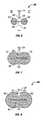
- FIG. 1is a diagrammatic sketch in a transverse sectional view thru a portion of the spine of a subject showing a plug in place according to the invention at a dural puncture site.
- FIG. 2is a diagrammatic sketch of a portion of a sectional view as in FIG. 1 , showing a barrier at the dural puncture site formed by swelling of the plug according to the invention.
- FIG. 3is a diagrammatic sketch in a lengthwise sectional view thru a plug in place at a dural puncture site according to an embodiment of the invention.
- FIG. 4is a diagrammatic sketch in a lengthwise sectional view showing a stage in the formation of a barrier from the plug of FIG. 3 .
- FIG. 5is a diagrammatic sketch in a lengthwise sectional view thru a barrier formed at the site of a dural puncture from the plug of FIG. 3 .
- FIG. 6is a diagrammatic sketch in a lengthwise sectional view thru a plug in place at a dural puncture site according to another embodiment of the invention.
- FIG. 7is a diagrammatic sketch in a lengthwise sectional view showing a stage in the formation of a barrier from the plug of FIG. 6 .
- FIG. 8is a diagrammatic sketch in a lengthwise sectional view thru a barrier formed at the site of a dural puncture from the plug of FIG. 6 .
- FIG. 9is a diagrammatic sketch in a lengthwise sectional view thru a plug in place at a dural puncture site according to yet another embodiment of the invention.
- FIG. 10is a diagrammatic sketch in a lengthwise sectional view showing a stage in the formation of a barrier from the plug of FIG. 9 .
- FIG. 11is a diagrammatic sketch in a lengthwise sectional view thru a barrier formed at the site of a dural puncture from the plug of FIG. 9 .
- FIGS. 12–15are diagrammatic sketches in a lengthwise sectional view showing stages in placement of a plug at a dural puncture site according to an embodiment of the invention.
- FIG. 16is a diagrammatic sketch in a lengthwise sectional view thru a plug in place at a dural puncture site according to yet another embodiment of the invention.
- FIG. 17is a diagrammatic sketch in a lengthwise sectional view showing a stage in the formation of a barrier from the plug of FIG. 16 .
- FIG. 18is a diagrammatic sketch in a lengthwise sectional view thru a barrier formed at the site of a dural puncture from the plug of FIG. 16 .
- FIGS. 19–20are diagrammatic views in sectional views thru a portion of a plug according to the invention, marked for reference to dimensions.
- FIGS. 21–30are diagrammatic sketches in side views ( 21 , 23 , 25 , 27 , 29 ) and axial views ( 22 , 24 , 26 , 28 , 30 ) of portions of plugs in various configurations according to the invention.
- FIG. 1there is shown a diagrammatic sectional view thru the spinal cord and associated structures, immediately following placement of a plug according to the invention within a puncture in the dura mater.
- the spinal dura mater 14forms a sheath around the spinal cord 17 .
- the spinal durais underlain at its inner surface 21 by the arachnoid and the spinal cord is invested on its outer surface 16 by the pia mater.
- An epidural space 13separates the dura 14 from the vertebral canal, defined at the level of the sectional view of FIGS. 1 and 2 by the vertebral body and, dorsally, by the ligamentum flavum 12 .
- the arachnoidis separated from the pia mater by the subarachnoid space 15 , which is filled with cerebrospinal fluid.
- Access to the subarachnoid space 15can be obtained by passing a needle or catheter (not shown in FIG. 1 or 2 ) through the intervertebral space between adjoining vertebrae.
- the needle or catheterpenetrates through the skin and subcutaneous fatty tissues (not shown in the Figs.), through the ligamentum flavum 12 , through the epidural space 13 , and through the dura 14 into the subarachnoid space 15 .
- an opening or rent 18remains in the dura at the site of the puncture.
- a biocompatible and biodegradable plug 19is placed at the site of the rent. At least part of the plug 19 is swellable in tissue fluids, and, after a short time generally in a scale of seconds or minutes, the plug swells in situ to form a barrier 20 that occludes the rent, as shown in FIG. 2 .
- the plugis gradually degraded over a time sufficient to permit the rent to close by healing.
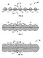
- FIGS. 3–5 , 6 – 8 , 9 – 11 , and 12 – 18Some exemplary embodiments of plugs and of barriers formed in situ by swelling of the plugs according to the invention are shown in FIGS. 3–5 , 6 – 8 , 9 – 11 , and 12 – 18 .
- the plug 30has a dumbbell shape, with a pair of wider parts 32 , 34 joined by a narrower connecting part 36 .
- the plugis placed at the site of the rent 28 such that one wider part 32 is in the volume 27 bounded by one surface of the membrane 24 and the other wider part 34 is within the volume 29 bounded by the other surface of the membrane 24 , and the connecting part 36 traverses the rent 28 .
- the connecting part as well as the larger partsare made of a swellable material. Within a short time following placement of the plug at the site of the rent (typically in the order of a few seconds) the material swells to engage the edge 26 of the rent 28 , occluding the opening.
- FIG. 4shows a barrier 50 resulting from the continued swelling of the plug material at the site of the rent.
- the medial regions 53 , 55 of the swollen wider parts 52 , 54engage the surfaces of the membrane at the margin of the rent, securing the barrier and preventing it from migrating away from the site.
- the barriereffectively obstructs movement or migration of fluids in either direction from one of the volumes 27 , 29 to the other across the rent.
- Suitable swellable materialsinclude biocompatible and biodegradable water-swellable polymers, including for example hydrogels.
- the swellable materialmay be of biological origin, either derived from biological tissues or made biosynthetically; or it may be of nonbiological origin. Suitable materials include gelatins, collagens, celluloses, agaroses, hyaluronic acid (HA), poly(vinyl alcohol) (PVA), polyethylene oxide (PEO), and the like. Where the material is of biological origin it must be substantially free of active infectious agents, including particularly viruses and prions.
- the swellable materialcan be a foamed gel, or a sponge, or a nonwoven mesh or felt, or the like. As one example, a foamed gelatin material distributed by Pharmacea and Upjohn under the name “GELFOAM®” may be particularly useful as a swellable material according to the invention.
- the swellable materialmay include combinations of constituents that slow or accelerate the swell rate, or increase or decrease the swell capacity to suit a particular use. And the swellable material may include combination of constituents that make the initially wetted surface of the material more slippery, so that it can be more easily passed through the lumen of a needle or catheter.
- the connecting part of the plugmay be made of a material different from that of the wider parts, and particularly, the connecting part may be made of a non water swellable material.
- the plug 50has a dumbbell shape, with a pair of wider parts 62 , 64 of a swellable material formed on a filament 66 of a non swellable material.
- the plugis placed at the site of the rent 28 such that one swellable wider part 62 is within the volume 27 bounded by one surface of the membrane 24 and the other swellable wider part 64 is within the volume 29 bounded by the other surface of the membrane 24 , and 80 portion of the filament 66 between the connected swellable parts traverses the rent 28 .
- the swellable parts 72 , 74swell to engage the edge 26 of the rent 28 , occluding the opening, as shown in FIG. 7 .
- a barrier 80is formed as a result of the continued swelling of the plug material at the site of the rent.
- the medial regions 83 , 85 of the swollen parts 82 , 84engage the surfaces of the membrane at the margin of the rent, securing the barrier, generally as described with reference to FIG. 5 .
- a plug as shown in FIG. 6is constructed by affixing a number of swellable parts onto a filament at intervals as if attaching beads on a strand, and then trimming the filament to form pairs of swellable parts 62 , 64 on a connecting part 66 .
- a dry foamed gelatin materialmay be cut to an appropriate size and then mechanically compressed about the filament.
- the filament forming the connecting partcan be provided, for example, as a sterile strand prepared from collagen derived from healthy mammal (for example from bovine gut serosa); or a synthetic polymer, such as a polyglycolate, or a polylactate, or a polydioxanone, or the like.
- the filamentmay be treated to modify its stiffness, or its resistance to absorption, or its tendency to wick; it may be impregnated or coated with a suitable antimicrobial agent; or it may be colored by an approved color additive.
- the filamentcan be a conventional absorbable suture material.
- the strength and stiffness of such a filamentwill depend upon mechanical properties of the filament material and upon the thickness (diameter; gauge) of the filament.
- the connecting functiondoes not demand that the filament be particularly strong or stiff.
- Any conventional suture material in any conventional suture gauge, for example,would be expected to have sufficient tensile strength to maintain the connection of the two swellable parts; and the plug need be only sufficiently stiff to maintain its orientation with respect to the rent during the earlier phase of swelling.
- the placement of the plug at the site of the rentmay be facilitated by providing a stiffer filament.
- the plug 90has swellable parts 92 , 94 affixed on a filament 96 as in the example of FIG. 6 ; but here, the filament is preferably stiff and some length 98 of the filament is left intact, to provide for ready manipulation of the plug during placement.
- the length 98 of the filamentcan serve, for example, as a stylet to guide the plug through tissues along a path to the site of the rent.
- the length 98 of the filamentcan serve to guide the plug within the lumen of a needle of catheter toward the site of the rent.
- plug 90forms a barrier 110 through stages of swelling in a manner generally analogous to that illustrated in FIGS. 7 and 8 .
- the swellable parts of plug 90swell so that they 102 , 204 engage the edge 26 of the rent as shown in FIG. 10 and swell further so that medial regions 113 , 115 of swollen parts 112 , 114 engage the surfaces of the membrane at the margins of the rent, securing the barrier 110 , as shown in FIG. 11 .
- FIGS. 1 , 3 , 6 and 9illustrate plug embodiments have a single pair of connected swellable wider portions, and for simplicity of presentation the plug is shown as being symmetrically disposed within the rent. It is not necessary that the plug be placed so that the plug axis (defined generally as a line running lengthwise through the connecting part) be oriented perpendicularly with respect to the membrane, nor that the plug axis be centered within the rent. Nor is it necessary that the plug be placed so that the two wider parts are equally distant from the plane of the rent.
- the plugin order for a barrier to form successfully according to the invention, occluding the rent as shown in FIGS. 2 , 5 , 8 and 11 , the plug must be placed so that the two wider portions are located on opposite sides of the membrane. If such a plug be advanced too far or not far enough, so that both swellable parts are in a space within the membrane or outside it, the wider parts will not engage the edge of the rent as they swell, and no barrier will form at the rent.
- the rent siteis hidden from view, and access to the rent site is by way of the lumen of a needle or a catheter, or by way of a path formed by a probe or blade.
- direct inspection of the sitecannot be employed to ensure that the plug is advanced to an appropriate position within the rent.
- no methodis currently available for visualizing the rent site in a spinal dural puncture.
- appropriate placementmay be made for example by employing an insertion stylet having length indicia or, for an embodiment such as in FIG. 9 , by employing length indicia on the extended length of the filament, and orienting the length indicia to the skin surface.
- length indicia on the stylet or filamentcan be aligned with indicia on the catheter or needle to establish the position of the plug in relation to the needle or catheter tip. So long as the position of the tip of the needle or catheter with respect to the membrane can be known with sufficient accuracy, the plug may in some such embodiments be placed appropriately by ejecting it from the tip of the stylet prior to withdrawal of the stylet or the needle. Or, in other such embodiments where an extended length of the filament serves as a stylet, the plug is left in place and the needle or catheter is withdrawn over the stylet.
- length indiciais well known for stylets, needles, catheters, cannulae and the like.
- the rent sitemay be visualized more directly. For example, in preparation for a cranial dural puncture, a portion of the skull is removed near the site, so that the dura is exposed to view. In such instances a direct visual check on the placement of the plug may be made.
- the plughas two connected swellable portions
- increasing the distance between the wider partscan increase the likelihood that the plug will be appropriately placed with the connecting portion traversing the rent.
- the degree to which the wider parts can swellis limited, however, by the properties of the swellable material and, accordingly, the extent to which the wider parts may be separated is also limited: if they are too far apart, then the swollen parts cannot securely engage the membrane surfaces at the margin of the rent, and no barrier will be formed.
- the plughas more than two wider swellable parts arranged in a string.
- This configurationincreases the overall length of the swellable portion of the plug without increasing the spacing between pairs of wider swellable parts, and it improves the likelihood that when the plug is placed at the rent site, a connected pair of wider swellable parts will be appropriately placed.
- the overall length of the swellable portionis double the length of a single pair of similarly spaced swellable parts; and either of two connecting pairs of swellable parts can find an appropriate location.
- FIG. 16showing a plug 160 having several swellable parts, seven of which ( 141 , 143 , 145 , 142 , 144 , 147 and 149 ) are shown in the Fig., arranged as beads on a filament 146 .
- the plug 160is inserted through the rent 18 and placed such that at least the most distal one 141 of the swellable parts is known with a reasonable certainty to be within the volume 27 on one side of the membrane 24 , and such that at least one more proximal swellable part, for example 149 , is known with a reasonable certainty to be within the volume 29 on the other side of the membrane. That placement having been accomplished, the connecting portion between an adjacent pair of swellable parts (between 142 and 144 in FIG.
- the medial regions 173 , 175 of the swelling parts 172 , 174engage the edge 26 of the rent as shown in FIG. 17 and swell further so that medial portions 183 , 185 of swollen parts 182 , 184 engage the surfaces of the membrane at the margins of the rent, securing the barrier 180 , as shown in FIG. 18 .
- FIGS. 12 through 15Placement of a plug 160 according to one embodiment of the invention is illustrated in FIGS. 12 through 15 .
- a dural needle 120is shown, having a wall 122 and a lumen 124 , and having an angled bevel 126 at the tip.
- Techniquesare well known for insertion of such a dural needle so that the tip is placed for access to the cerebrospinal fluid within the subarachnoid space 27 .
- the needlepasses through (among other anatomical features) the epidural space 29 and the dura 24 , in which the needle cuts an edge 26 defining a dural puncture.
- the operatorcan feel the puncture of the dura as the needle is forced through it (sometimes referred to as the dural “pop”), and care is taken as a matter of course not to advance the tip of the needle more than a few millimeters (or less) beyond that point.
- the needle 120is placed for any of a variety of purposes that call for access to the cerebrospinal fluid in the subarachnoid space: withdrawal of a sample of CSF, for example, or introduction of an anesthetic.
- the dural plugcan be inserted by way of the lumen 124 of the same needle 120 whose deployment created the dural puncture.
- a dural plugas shown for example in any of FIG.
- FIGS. 13–15illustrate placement of a plug having several swellable parts serially spaced on a filament, as described above with reference to FIG. 16 .
- the plug 160is passed within the lumen 124 toward the tip of the needle 120 , as indicated by arrow 130 in FIG. 13 .
- the plug 160includes several swellable parts (e.g., 132 , 134 ) affixed at intervals on a filament 136 .
- the filament 136is sufficiently stiff that it serves to maintain the spacing and the axial alignment of the swellable parts as the plug is passed through the needle.
- a separate stylet or other pushermay be employed to press the plug through the needle.
- a proximal extended length of the filament(not shown in FIGS.
- the pusher or stylet or extended length of the filamentmay be marked with length indicia, so that the progress of the plug toward the tip of the needle may be monitored.
- the plugis advanced until, as is shown for example in FIG. 14 , the operator is reasonably certain that at least the most distal swellable part 141 is inside the membrane (within the subarachnoid space in this illustration) and that at least one more proximal swellable part (e.g., 149 ) is within a section of the needle that is outside the membrane (in the epidural space in this illustration).
- the needleis withdrawn as indicted by the arrow 150 in FIG. 15 , while the position of the plug 160 is maintained.
- the needlewere deployed more or less deeply beyond the rent than is shown in this illustration, or if the plug were advanced more or less far within the needle than is shown, then a different connected pair of swellable portions would have come into play in the formation of the barrier.
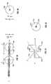
- FIGS. 19 and 20are sectional views showing a portion of such a plug 190 , including several swellable parts and connecting parts between them, marked for illustration of a range of dimensions that the various features of the plug may have according to the invention.
- FIG. 19is a lengthwise sectional view made along an axis A defined by the centerline of the connecting part or filament 196
- FIG. 20is a sectional view through a swellable part or bead (e.g., 192 or 194 ) in a plane transverse to the axis A.
- the connecting part or filament 196has a diameter F, and the swellable parts or beads 192 , 194 have a transverse width W as measured in the plane T transverse to the axis A. Adjacent swellable parts or beads 192 , 194 are spaced apart by a pitch P measured lengthwise between respective points 193 , 195 of greatest transverse width.
- the transverse width Wis determined by the lumenal dimension, that is, by the inside diameter of the needle or catheter. Generally, the greatest transverse width W must be somewhat smaller than the inside diameter, so that the plug may be passed through the lumen of the needle or catheter with little or no frictional resistance.
- the dimensions of the defect in the membranedepend particularly upon the outside diameter of the needle that was used to create the puncture, as well as the configuration of the tip of the needle and technique employed. In order to form a secure barrier, the deployed plug will have to be capable of swelling to engage the membrane at the rent, as described with reference to for example to FIGS. 4 and 5 .
- the pitch Pis determined by consideration of the size of the swellable parts or beads and of the dimensional swell capacity of the material of which they are made. That is, referring again to FIGS. 3–5 , the pitch is determined such that as the swellable material swells ( FIG. 4 ) the medial regions 43 , 45 of the swelling parts 42 , 44 swell against the surfaces of the membrane 24 at the edge of the rent, and then continue to swell ( FIG. 5 ) until the medial regions 53 , 55 of the swelling parts 52 , 54 engage the surfaces of the membrane at the margin of the rent, securing the barrier. If the swellable parts or beads are made of a material having a lower dimensional swell capacity, then the beads can be pitched closer together to achieve this result.
- the series of swellable parts or beadsconstitute the swellable portion 191 of the plug 190 .
- the length L of the swellable portion 191 of the plug 190is determined by the number of swellable parts or beads and by the spacing between them. As explained above with reference to FIGS. 12 to 18 , the length L is selected to assure that, within a reasonable certainty, the connecting part between an adjacent pair of swellable parts or beads will traverse the rent following deployment of the plug at the site. That is, given a preferred pitch P, the swellable portion of the plug will include a sufficient number of swellable parts or beads to provide a length L that will span the greatest likely margin of error in positioning the plug at the site.
- the swellable parts of the plug according to the inventionmay have any of a wide variety of shapes. What is required is that at least two connected wider swellable parts have a narrower region between them, so that the plug can be placed at the rent site such that the wider parts are situated on opposite sides of the membrane or wall, with the narrower region traversing the rent.
- FIGS. 21–30show a few illustrative examples of suitable configurations.
- each of FIGS. 21 , 23 , 25 , 27 and 29is a side view of a portion of two connected wider adjacent swellable parts or beads of a plug body according to an embodiment of the invention
- each of FIGS. 22 , 24 , 26 , 28 and 30is an axial view (along A—A taken as indicated) of one of the wider swellable parts or beads.
- FIGS. 21–30show a few illustrative examples of suitable configurations.
- FIGS. 21 , 23 , 25 , 27 and 29is a side view of a portion of two connected wider adjacent swellable parts or beads of a plug body according to an embodiment of the invention
- each of FIGS. 22 , 24 , 26 , 28 and 30is an axial view (along A—A taken as indicated) of one of the wider swellable parts or beads.
- Tindicates a plane transverse to the axis A—A at the place where the width of a wider swellable part or bead is greatest, and only that portion of the swellable parts or beads that is between the planes T is shown.
- the plugis narrower between the wider swellable parts or beads.
- the swellable portion of a plug according to the inventionmay have more than two wider swellable parts or beads, although portions of only two adjacent ones are shown here.
- each wider swellable part or beadmay be symmetrical with respect to the plane T, but it is not necessarily so; also, adjacent wider swellable parts or beads may be similarly shaped, as is shown in these Figs., but adjacent wider swellable parts or beads may according to the invention be shaped differently.
- FIG. 21shows a portion of two swellable beads 212 , 214 connected on a non-swellable filament 216 .
- Each beadis elongated axially toward the adjacent bead, so that each bead tapers from its wider point 213 , 215 toward the filament 216 .
- the narrower region between the wider points of the beadsis the diameter of the filament; but in this embodiment a transition between the wider and narrower regions is more gradual than is provided by the spherical or spheroidal bead configuration as in FIG. 19 .
- each beadmay have an edge or rim, as shown for example in FIG. 23 .
- each of the illustrated bead portions 232 , 234is generally conical, tapering from its widest point 233 , 235 toward the filament 236 .
- the plugin the case where the plug is deployed with the opening in the membrane very close to the widest point of a bead, the plug may self-adjust as it swells, moving axially in one direction or the other to capture the membrane or wall between adjacent beads more effectively than would a plug having a more rounded configuration as shown for example in FIG. 19 or FIG. 21 .
- the narrower region between the adjacent beadsis the diameter of the filament.
- the narrower region 257 between adjacent wider swellable parts 252 , 254may, in some embodiments, have swellable material surrounding the filament 256 .
- Thismay increase the capacity of the swellable material to effectively fill the rent, particularly in applications where the wall or membrane is thicker and the beads or wider swellable portions are more widely spaced apart. That is, it is not necessary nor is it in some applications desirable that the narrower region be as narrow as the filament; in practice it need only be narrow enough to permit the adjacent swellable parts to engage the surfaces of the wall or membrane at the margin of the rent, and thereby securing the barrier in place within the rent site.
- FIGS. 22 , 24 and 26show the bead as circular at its widest point and centered at the axis of the filament. It may according to the invention be round or rounded yet non-circular, for example oval or ovoid. Or, other shapes are possible according to the invention, as FIGS. 27–30 show by way of illustration.
- each beadmay have a polygonal shape at its widest point (hexagonal in the Figs., by way of example), so that each of the illustrated bead portions has a pyramidal or truncated pyramidal shape.
- each of bead portions 272 , 274 in FIGS. 27 and 28has a polygonal (hexagonal) shape at the wider point 273 , 275 and then tapers as a pyramid to a truncation point, e.g., 277 .
- the narrower point in this embodimentis the diameter of the filament 276 , and the filament 276 is bare over a significant part of the separation between the beads, and in this respect is similar to a configuration having spheroidal beads on a filament as illustrated in FIG. 19 .
- each of bead portions 292 , 294has a polygonal (here hexagonal) shape at the wider point 293 , 296 and then tapers as a truncated pyramid; but here the pyramids meet at the narrower point 297 , to provide some swellable material surrounding the filament 296 .
- the inventioncan be useful in surgical procedures in the fields of endoscopy, laparoscopy, orthoscopy, bronchoscopy, and others.
- the aortamay be accessed from within the stomach by way of a puncture through the stomach wall, using an esophageal endoscope; according to the invention, a barrier can be formed in the rent in the stomach wall at the completion of the procedure.
- a transurethral cathetercannot be placed, a superpubic puncture of the urinary bladder may be made; a barrier can be formed according to the invention to prevent leakage of urine into the peritoneal cavity through the rent in the bladder wall.
- the inventioncan also be employed in conjunction with any of a variety of medical procedures in which a puncture or rent is formed unintentionally.
- an unintentional puncturemay occur in the course of any of various minimally invasive procedures involving access by way of the lumen of a hollow organ of the body, as for example in various procedures in urology or gastroenterology; such complications are regrettably high, but can be mitigated by using a barrier formed according to the invention to control movement of fluids or fluid-borne materials through the puncture.
Landscapes
- Health & Medical Sciences (AREA)
- Surgery (AREA)
- Life Sciences & Earth Sciences (AREA)
- Medical Informatics (AREA)
- Nuclear Medicine, Radiotherapy & Molecular Imaging (AREA)
- Engineering & Computer Science (AREA)
- Biomedical Technology (AREA)
- Heart & Thoracic Surgery (AREA)
- Cardiology (AREA)
- Molecular Biology (AREA)
- Animal Behavior & Ethology (AREA)
- General Health & Medical Sciences (AREA)
- Public Health (AREA)
- Veterinary Medicine (AREA)
- Media Introduction/Drainage Providing Device (AREA)
- Materials For Medical Uses (AREA)
Abstract
Description
Claims (20)
Priority Applications (5)
| Application Number | Priority Date | Filing Date | Title |
|---|---|---|---|
| US10/114,662US6932833B1 (en) | 2002-04-01 | 2002-04-01 | Method and barrier for limiting fluid movement through a tissue rent |
| PCT/US2003/009652WO2003084389A2 (en) | 2002-04-01 | 2003-03-31 | Method and barrier for limiting fluid movement through a tissue rent |
| AU2003233456AAU2003233456A1 (en) | 2002-04-01 | 2003-03-31 | Method and barrier for limiting fluid movement through a tissue rent |
| TW092107392ATW200403039A (en) | 2002-04-01 | 2003-04-01 | Method and barrier for limiting fluid movement through a tissue rent |
| US11/194,427US20050267527A1 (en) | 2002-04-01 | 2005-08-01 | Method and barrier for limiting fluid movement through a tissue rent |
Applications Claiming Priority (1)
| Application Number | Priority Date | Filing Date | Title |
|---|---|---|---|
| US10/114,662US6932833B1 (en) | 2002-04-01 | 2002-04-01 | Method and barrier for limiting fluid movement through a tissue rent |
Related Child Applications (1)
| Application Number | Title | Priority Date | Filing Date |
|---|---|---|---|
| US11/194,427DivisionUS20050267527A1 (en) | 2002-04-01 | 2005-08-01 | Method and barrier for limiting fluid movement through a tissue rent |
Publications (1)
| Publication Number | Publication Date |
|---|---|
| US6932833B1true US6932833B1 (en) | 2005-08-23 |
Family
ID=28789802
Family Applications (2)
| Application Number | Title | Priority Date | Filing Date |
|---|---|---|---|
| US10/114,662Expired - Fee RelatedUS6932833B1 (en) | 2002-04-01 | 2002-04-01 | Method and barrier for limiting fluid movement through a tissue rent |
| US11/194,427AbandonedUS20050267527A1 (en) | 2002-04-01 | 2005-08-01 | Method and barrier for limiting fluid movement through a tissue rent |
Family Applications After (1)
| Application Number | Title | Priority Date | Filing Date |
|---|---|---|---|
| US11/194,427AbandonedUS20050267527A1 (en) | 2002-04-01 | 2005-08-01 | Method and barrier for limiting fluid movement through a tissue rent |
Country Status (4)
| Country | Link |
|---|---|
| US (2) | US6932833B1 (en) |
| AU (1) | AU2003233456A1 (en) |
| TW (1) | TW200403039A (en) |
| WO (1) | WO2003084389A2 (en) |
Cited By (28)
| Publication number | Priority date | Publication date | Assignee | Title |
|---|---|---|---|---|
| US7189235B2 (en) | 1999-10-20 | 2007-03-13 | Anulex Technologies, Inc. | Spinal disc annulus reconstruction method and spinal disc annulus stent |
| US20080195202A1 (en)* | 2007-02-12 | 2008-08-14 | Lauritzen Nels J | Methods for Collagen Processing and Products Using Processed Collagen |
| US20080228200A1 (en)* | 2007-03-16 | 2008-09-18 | Clinton Baird | Closure and reconstruction implants and the apparatus for delivery thereof |
| US20080262514A1 (en)* | 2007-04-20 | 2008-10-23 | Christoph Gasche | Systems and methods for endoscopic treatment of diverticula |
| US20080260794A1 (en)* | 2007-02-12 | 2008-10-23 | Lauritzen Nels J | Collagen products and methods for producing collagen products |
| US20080312495A1 (en)* | 2007-06-12 | 2008-12-18 | Mcwilliams Dennis L | Method of Performing Transgastric Abdominal Surgery |
| US20090227938A1 (en)* | 2008-03-05 | 2009-09-10 | Insitu Therapeutics, Inc. | Wound Closure Devices, Methods of Use, and Kits |
| US7615076B2 (en) | 1999-10-20 | 2009-11-10 | Anulex Technologies, Inc. | Method and apparatus for the treatment of the intervertebral disc annulus |
| US20100174306A1 (en)* | 2007-07-11 | 2010-07-08 | Vladimir Mitelberg | Methods and Systems for Performing Submucosal Medical Procedures |
| US7828850B2 (en) | 1999-10-20 | 2010-11-09 | Anulex Technologies, Inc. | Methods and devices for spinal disc annulus reconstruction and repair |
| US7922768B2 (en) | 1999-10-20 | 2011-04-12 | Anulex Technologies, Inc. | Spinal disc annulus reconstruction method and deformable spinal disc annulus stent |
| US7935147B2 (en) | 1999-10-20 | 2011-05-03 | Anulex Technologies, Inc. | Method and apparatus for enhanced delivery of treatment device to the intervertebral disc annulus |
| US7951201B2 (en) | 1999-10-20 | 2011-05-31 | Anulex Technologies, Inc. | Method and apparatus for the treatment of the intervertebral disc annulus |
| US8066689B2 (en) | 2007-07-11 | 2011-11-29 | Apollo Endosurgery, Inc. | Methods and systems for submucosal implantation of a device for diagnosis and treatment with a therapeutic agent |
| US8128698B2 (en) | 1999-10-20 | 2012-03-06 | Anulex Technologies, Inc. | Method and apparatus for the treatment of the intervertebral disc annulus |
| US8128592B2 (en) | 2007-07-11 | 2012-03-06 | Apollo Endosurgery, Inc. | Methods and systems for performing submucosal medical procedures |
| US8163022B2 (en) | 2008-10-14 | 2012-04-24 | Anulex Technologies, Inc. | Method and apparatus for the treatment of the intervertebral disc annulus |
| US8460691B2 (en) | 2010-04-23 | 2013-06-11 | Warsaw Orthopedic, Inc. | Fenestrated wound repair scaffold |
| US8460319B2 (en) | 2010-01-11 | 2013-06-11 | Anulex Technologies, Inc. | Intervertebral disc annulus repair system and method |
| US8556977B2 (en) | 1999-10-20 | 2013-10-15 | Anulex Technologies, Inc. | Tissue anchoring system and method |
| US8790699B2 (en) | 2010-04-23 | 2014-07-29 | Warsaw Orthpedic, Inc. | Foam-formed collagen strand |
| US8929988B2 (en) | 2007-07-11 | 2015-01-06 | Apollo Endosurgery, Inc. | Methods and systems for submucosal implantation of a device for diagnosis and treatment of a body |
| US9737294B2 (en) | 2013-01-28 | 2017-08-22 | Cartiva, Inc. | Method and system for orthopedic repair |
| US9848763B2 (en) | 2008-05-15 | 2017-12-26 | Apollo Endosurgery Us, Inc. | Access systems and methods of intra-abdominal surgery |
| US10058330B2 (en) | 2011-05-11 | 2018-08-28 | Microvention, Inc. | Device for occluding a lumen |
| US10179012B2 (en) | 2013-01-28 | 2019-01-15 | Cartiva, Inc. | Systems and methods for orthopedic repair |
| US10278691B2 (en)* | 2011-02-10 | 2019-05-07 | Coloplast A/S | Suture assembly including a suture clip |
| US10363027B2 (en) | 2010-12-02 | 2019-07-30 | Coloplast A/S | Suture assembly including a suture attached to a leader |
Families Citing this family (13)
| Publication number | Priority date | Publication date | Assignee | Title |
|---|---|---|---|---|
| US9307995B2 (en) | 2006-06-15 | 2016-04-12 | Cook Medical Technologies Llc | Methods, systems and devices for the delivery of endoluminal prostheses |
| WO2008010738A2 (en)* | 2007-01-24 | 2008-01-24 | Uros Babic | Patent foramen ovale occluder with suture based anchor |
| US20080188892A1 (en)* | 2007-02-01 | 2008-08-07 | Cook Incorporated | Vascular occlusion device |
| US9743918B2 (en) | 2008-01-18 | 2017-08-29 | St. Jude Medical, Cardiology Division, Inc. | Percutaneous catheter directed intravascular occlusion device |
| EP2633823B1 (en) | 2008-04-21 | 2016-06-01 | Covidien LP | Braid-ball embolic devices and delivery systems |
| WO2009140437A1 (en) | 2008-05-13 | 2009-11-19 | Nfocus Neuromedical, Inc. | Braid implant delivery systems |
| US9271706B2 (en)* | 2008-08-12 | 2016-03-01 | Covidien Lp | Medical device for wound closure and method of use |
| US8876870B2 (en) | 2010-04-27 | 2014-11-04 | Adnan Iqbal Qureshi | Intraspinal device deployed through percutaneous approach into subarachnoid or intradural space of vertebral canal to protect spinal cord from external compression |
| WO2011155988A1 (en)* | 2010-06-10 | 2011-12-15 | Colantonio Anthony J | Apparatus and method for safely inserting an introducer needle into epidural space |
| US10327781B2 (en) | 2012-11-13 | 2019-06-25 | Covidien Lp | Occlusive devices |
| US10576099B2 (en) | 2016-10-21 | 2020-03-03 | Covidien Lp | Injectable scaffold for treatment of intracranial aneurysms and related technology |
| WO2021092618A1 (en) | 2019-11-04 | 2021-05-14 | Covidien Lp | Devices, systems, and methods for treatment of intracranial aneurysms |
| WO2021211213A1 (en)* | 2020-04-14 | 2021-10-21 | Deinde Medical Corp. | Closure devices and methods for sealing biologic tissue membranes |
Citations (53)
| Publication number | Priority date | Publication date | Assignee | Title |
|---|---|---|---|---|
| US3742955A (en) | 1970-09-29 | 1973-07-03 | Fmc Corp | Fibrous collagen derived product having hemostatic and wound binding properties |
| US4231369A (en) | 1977-05-24 | 1980-11-04 | Coloplast International A/S | Sealing material for ostomy devices |
| US4390018A (en) | 1980-09-15 | 1983-06-28 | Zukowski Henry J | Method for preventing loss of spinal fluid after spinal tap |
| US4890612A (en) | 1987-02-17 | 1990-01-02 | Kensey Nash Corporation | Device for sealing percutaneous puncture in a vessel |
| US5053046A (en) | 1988-08-22 | 1991-10-01 | Woodrow W. Janese | Dural sealing needle and method of use |
| EP0493810A1 (en) | 1990-12-27 | 1992-07-08 | NOVOSTE CORPORATION (a Florida Corporation) | Wound clotting device |
| US5152759A (en) | 1989-06-07 | 1992-10-06 | University Of Miami, School Of Medicine, Dept. Of Ophthalmology | Noncontact laser microsurgical apparatus |
| US5192301A (en) | 1989-01-17 | 1993-03-09 | Nippon Zeon Co., Ltd. | Closing plug of a defect for medical use and a closing plug device utilizing it |
| US5192326A (en)* | 1990-12-21 | 1993-03-09 | Pfizer Hospital Products Group, Inc. | Hydrogel bead intervertebral disc nucleus |
| US5192302A (en) | 1989-12-04 | 1993-03-09 | Kensey Nash Corporation | Plug devices for sealing punctures and methods of use |
| US5258042A (en) | 1991-12-16 | 1993-11-02 | Henry Ford Health System | Intravascular hydrogel implant |
| US5320639A (en) | 1993-03-12 | 1994-06-14 | Meadox Medicals, Inc. | Vascular plug delivery system |
| US5370660A (en) | 1993-11-01 | 1994-12-06 | Cordis Corporation | Apparatus and method for delivering a vessel plug into the body of a patient |
| US5447502A (en) | 1988-05-26 | 1995-09-05 | Haaga; John R. | Sheath for wound closure caused by a medical tubular device |
| US5456693A (en) | 1992-09-21 | 1995-10-10 | Vitaphore Corporation | Embolization plugs for blood vessels |
| US5486195A (en) | 1993-07-26 | 1996-01-23 | Myers; Gene | Method and apparatus for arteriotomy closure |
| US5571181A (en) | 1992-05-11 | 1996-11-05 | Li; Shu-Tung | Soft tissue closure systems |
| US5573519A (en) | 1993-09-09 | 1996-11-12 | Zohmann; Walter A. | Atraumatic needle for lumbar puncture |
| US5628734A (en) | 1995-03-23 | 1997-05-13 | Hatfalvi; Bela I. | Spinal needle with curved distal end and method of using said needle in a spinal injection to prevent post dural puncture headache |
| US5634936A (en) | 1995-02-06 | 1997-06-03 | Scimed Life Systems, Inc. | Device for closing a septal defect |
| US5643318A (en) | 1994-03-31 | 1997-07-01 | Boston Scientific Corporation | Vascular plug with vessel locator |
| US5649959A (en) | 1995-02-10 | 1997-07-22 | Sherwood Medical Company | Assembly for sealing a puncture in a vessel |
| US5725551A (en) | 1993-07-26 | 1998-03-10 | Myers; Gene | Method and apparatus for arteriotomy closure |
| US5733545A (en) | 1995-03-03 | 1998-03-31 | Quantic Biomedical Partners | Platelet glue wound sealant |
| US5782860A (en) | 1997-02-11 | 1998-07-21 | Biointerventional Corporation | Closure device for percutaneous occlusion of puncture sites and tracts in the human body and method |
| US5834029A (en) | 1994-07-20 | 1998-11-10 | Cytotherapeutics, Inc. | Nerve guidance channel containing bioartificial three-dimensional hydrogel extracellular matrix derivatized with cell adhesive peptide fragment |
| US5861003A (en) | 1996-10-23 | 1999-01-19 | The Cleveland Clinic Foundation | Apparatus and method for occluding a defect or aperture within body surface |
| US5902832A (en)* | 1996-08-20 | 1999-05-11 | Menlo Care, Inc. | Method of synthesizing swollen hydrogel for sphincter augmentation |
| US5904703A (en) | 1996-05-08 | 1999-05-18 | Bard Connaught | Occluder device formed from an open cell foam material |
| US5951589A (en) | 1997-02-11 | 1999-09-14 | Biointerventional Corporation | Expansile device for use in blood vessels and tracts in the body and tension application device for use therewith and method |
| US5976174A (en) | 1997-12-15 | 1999-11-02 | Ruiz; Carlos E. | Medical hole closure device and methods of use |
| US5989215A (en) | 1995-01-16 | 1999-11-23 | Baxter International Inc. | Fibrin delivery device and method for forming fibrin on a surface |
| US5997895A (en) | 1997-09-16 | 1999-12-07 | Integra Lifesciences Corporation | Dural/meningeal repair product using collagen matrix |
| US6022361A (en) | 1998-10-09 | 2000-02-08 | Biointerventional Corporation | Device for introducing and polymerizing polymeric biomaterials in the human body and method |
| US6045570A (en) | 1997-02-11 | 2000-04-04 | Biointerventional Corporation | Biological sealant mixture and system for use in percutaneous occlusion of puncture sites and tracts in the human body and method |
| US6056770A (en) | 1997-02-11 | 2000-05-02 | Biointerventional Corporation | Expansile device for use in blood vessels and tracts in the body and method |
| US6056769A (en) | 1997-02-11 | 2000-05-02 | Biointerventional Corporation | Expansile device for use in blood vessels and tracts in the body and tension application device for use therewith and method |
| US6096021A (en) | 1998-03-30 | 2000-08-01 | The University Of Virginia Patent Foundation | Flow arrest, double balloon technique for occluding aneurysms or blood vessels |
| US6177095B1 (en) | 1996-09-23 | 2001-01-23 | Focal, Inc | Polymerizable biodegradable polymers including carbonate or dioxanone linkages |
| US6183498B1 (en) | 1999-09-20 | 2001-02-06 | Devore Dale P. | Methods and products for sealing a fluid leak in a tissue |
| US6268405B1 (en) | 1999-05-04 | 2001-07-31 | Porex Surgical, Inc. | Hydrogels and methods of making and using same |
| US6274090B1 (en) | 1998-08-05 | 2001-08-14 | Thermogenesis Corp. | Apparatus and method of preparation of stable, long term thrombin from plasma and thrombin formed thereby |
| US6296657B1 (en) | 1998-10-07 | 2001-10-02 | Gregory G. Brucker | Vascular sealing device and method |
| US6319263B1 (en) | 1999-07-13 | 2001-11-20 | Scion Cardio-Vascular, Inc. | Suture with toggle and delivery system |
| US20010046518A1 (en) | 1998-08-14 | 2001-11-29 | Amarpreet S. Sawhney | Methods of using in situ hydration of hydrogel articles for sealing or augmentation of tissue or vessels |
| US6334865B1 (en) | 1998-08-04 | 2002-01-01 | Fusion Medical Technologies, Inc. | Percutaneous tissue track closure assembly and method |
| US6352710B2 (en) | 1996-03-22 | 2002-03-05 | Focal, Inc. | Compliant tissue sealants |
| US6395292B2 (en) | 1996-02-02 | 2002-05-28 | Alza Corporation | Sustained delivery of an active agent using an implantable system |
| US20020120276A1 (en) | 1999-10-04 | 2002-08-29 | Microvention, Inc. | Filamentous embolic device with expansile elements |
| US6447534B2 (en) | 1998-05-01 | 2002-09-10 | Sub-Q, Inc. | Device and method for facilitating hemostasis of a biopsy tract |
| US20030014075A1 (en) | 2001-07-16 | 2003-01-16 | Microvention, Inc. | Methods, materials and apparatus for deterring or preventing endoleaks following endovascular graft implanation |
| US6514271B2 (en)* | 1997-10-29 | 2003-02-04 | Kensey Nash Corporation | Transmyocardial revascularization system and method of use |
| US20030109899A1 (en) | 2001-12-07 | 2003-06-12 | Fisher John S. | Bioabsorbable sealant |
- 2002
- 2002-04-01USUS10/114,662patent/US6932833B1/ennot_activeExpired - Fee Related
- 2003
- 2003-03-31WOPCT/US2003/009652patent/WO2003084389A2/ennot_activeApplication Discontinuation
- 2003-03-31AUAU2003233456Apatent/AU2003233456A1/ennot_activeAbandoned
- 2003-04-01TWTW092107392Apatent/TW200403039A/enunknown
- 2005
- 2005-08-01USUS11/194,427patent/US20050267527A1/ennot_activeAbandoned
Patent Citations (56)
| Publication number | Priority date | Publication date | Assignee | Title |
|---|---|---|---|---|
| US3742955A (en) | 1970-09-29 | 1973-07-03 | Fmc Corp | Fibrous collagen derived product having hemostatic and wound binding properties |
| US4231369A (en) | 1977-05-24 | 1980-11-04 | Coloplast International A/S | Sealing material for ostomy devices |
| US4390018A (en) | 1980-09-15 | 1983-06-28 | Zukowski Henry J | Method for preventing loss of spinal fluid after spinal tap |
| US4890612A (en) | 1987-02-17 | 1990-01-02 | Kensey Nash Corporation | Device for sealing percutaneous puncture in a vessel |
| US5447502A (en) | 1988-05-26 | 1995-09-05 | Haaga; John R. | Sheath for wound closure caused by a medical tubular device |
| US5053046A (en) | 1988-08-22 | 1991-10-01 | Woodrow W. Janese | Dural sealing needle and method of use |
| US5192301A (en) | 1989-01-17 | 1993-03-09 | Nippon Zeon Co., Ltd. | Closing plug of a defect for medical use and a closing plug device utilizing it |
| US5152759A (en) | 1989-06-07 | 1992-10-06 | University Of Miami, School Of Medicine, Dept. Of Ophthalmology | Noncontact laser microsurgical apparatus |
| US5192302A (en) | 1989-12-04 | 1993-03-09 | Kensey Nash Corporation | Plug devices for sealing punctures and methods of use |
| US5192326A (en)* | 1990-12-21 | 1993-03-09 | Pfizer Hospital Products Group, Inc. | Hydrogel bead intervertebral disc nucleus |
| EP0493810A1 (en) | 1990-12-27 | 1992-07-08 | NOVOSTE CORPORATION (a Florida Corporation) | Wound clotting device |
| US5258042A (en) | 1991-12-16 | 1993-11-02 | Henry Ford Health System | Intravascular hydrogel implant |
| US5571181A (en) | 1992-05-11 | 1996-11-05 | Li; Shu-Tung | Soft tissue closure systems |
| US5456693A (en) | 1992-09-21 | 1995-10-10 | Vitaphore Corporation | Embolization plugs for blood vessels |
| US5320639A (en) | 1993-03-12 | 1994-06-14 | Meadox Medicals, Inc. | Vascular plug delivery system |
| US5486195A (en) | 1993-07-26 | 1996-01-23 | Myers; Gene | Method and apparatus for arteriotomy closure |
| US5725551A (en) | 1993-07-26 | 1998-03-10 | Myers; Gene | Method and apparatus for arteriotomy closure |
| US5573519A (en) | 1993-09-09 | 1996-11-12 | Zohmann; Walter A. | Atraumatic needle for lumbar puncture |
| US5370660A (en) | 1993-11-01 | 1994-12-06 | Cordis Corporation | Apparatus and method for delivering a vessel plug into the body of a patient |
| US5643318A (en) | 1994-03-31 | 1997-07-01 | Boston Scientific Corporation | Vascular plug with vessel locator |
| US5834029A (en) | 1994-07-20 | 1998-11-10 | Cytotherapeutics, Inc. | Nerve guidance channel containing bioartificial three-dimensional hydrogel extracellular matrix derivatized with cell adhesive peptide fragment |
| US5989215A (en) | 1995-01-16 | 1999-11-23 | Baxter International Inc. | Fibrin delivery device and method for forming fibrin on a surface |
| US6074663A (en) | 1995-01-16 | 2000-06-13 | Baxter International Inc. | Method of using cross-linked fibrin material |
| US5634936A (en) | 1995-02-06 | 1997-06-03 | Scimed Life Systems, Inc. | Device for closing a septal defect |
| US5649959A (en) | 1995-02-10 | 1997-07-22 | Sherwood Medical Company | Assembly for sealing a puncture in a vessel |
| US5733545A (en) | 1995-03-03 | 1998-03-31 | Quantic Biomedical Partners | Platelet glue wound sealant |
| US5628734A (en) | 1995-03-23 | 1997-05-13 | Hatfalvi; Bela I. | Spinal needle with curved distal end and method of using said needle in a spinal injection to prevent post dural puncture headache |
| US6395292B2 (en) | 1996-02-02 | 2002-05-28 | Alza Corporation | Sustained delivery of an active agent using an implantable system |
| US6352710B2 (en) | 1996-03-22 | 2002-03-05 | Focal, Inc. | Compliant tissue sealants |
| US5904703A (en) | 1996-05-08 | 1999-05-18 | Bard Connaught | Occluder device formed from an open cell foam material |
| US5902832A (en)* | 1996-08-20 | 1999-05-11 | Menlo Care, Inc. | Method of synthesizing swollen hydrogel for sphincter augmentation |
| US6177095B1 (en) | 1996-09-23 | 2001-01-23 | Focal, Inc | Polymerizable biodegradable polymers including carbonate or dioxanone linkages |
| US5861003A (en) | 1996-10-23 | 1999-01-19 | The Cleveland Clinic Foundation | Apparatus and method for occluding a defect or aperture within body surface |
| US5782860A (en) | 1997-02-11 | 1998-07-21 | Biointerventional Corporation | Closure device for percutaneous occlusion of puncture sites and tracts in the human body and method |
| US6045570A (en) | 1997-02-11 | 2000-04-04 | Biointerventional Corporation | Biological sealant mixture and system for use in percutaneous occlusion of puncture sites and tracts in the human body and method |
| US6056770A (en) | 1997-02-11 | 2000-05-02 | Biointerventional Corporation | Expansile device for use in blood vessels and tracts in the body and method |
| US6056769A (en) | 1997-02-11 | 2000-05-02 | Biointerventional Corporation | Expansile device for use in blood vessels and tracts in the body and tension application device for use therewith and method |
| US5922009A (en) | 1997-02-11 | 1999-07-13 | Biointerventional Coporation | Expansile device for use in blood vessels and tracts in the body and tension application device for use therewith and method |
| US5951589A (en) | 1997-02-11 | 1999-09-14 | Biointerventional Corporation | Expansile device for use in blood vessels and tracts in the body and tension application device for use therewith and method |
| US5997895A (en) | 1997-09-16 | 1999-12-07 | Integra Lifesciences Corporation | Dural/meningeal repair product using collagen matrix |
| US6514271B2 (en)* | 1997-10-29 | 2003-02-04 | Kensey Nash Corporation | Transmyocardial revascularization system and method of use |
| US5976174A (en) | 1997-12-15 | 1999-11-02 | Ruiz; Carlos E. | Medical hole closure device and methods of use |
| US6096021A (en) | 1998-03-30 | 2000-08-01 | The University Of Virginia Patent Foundation | Flow arrest, double balloon technique for occluding aneurysms or blood vessels |
| US6447534B2 (en) | 1998-05-01 | 2002-09-10 | Sub-Q, Inc. | Device and method for facilitating hemostasis of a biopsy tract |
| US6334865B1 (en) | 1998-08-04 | 2002-01-01 | Fusion Medical Technologies, Inc. | Percutaneous tissue track closure assembly and method |
| US6274090B1 (en) | 1998-08-05 | 2001-08-14 | Thermogenesis Corp. | Apparatus and method of preparation of stable, long term thrombin from plasma and thrombin formed thereby |
| US20010046518A1 (en) | 1998-08-14 | 2001-11-29 | Amarpreet S. Sawhney | Methods of using in situ hydration of hydrogel articles for sealing or augmentation of tissue or vessels |
| US20020165581A1 (en) | 1998-10-07 | 2002-11-07 | Brucker Gregory G. | Vascular sealing device and method |
| US6296657B1 (en) | 1998-10-07 | 2001-10-02 | Gregory G. Brucker | Vascular sealing device and method |
| US6022361A (en) | 1998-10-09 | 2000-02-08 | Biointerventional Corporation | Device for introducing and polymerizing polymeric biomaterials in the human body and method |
| US6268405B1 (en) | 1999-05-04 | 2001-07-31 | Porex Surgical, Inc. | Hydrogels and methods of making and using same |
| US6319263B1 (en) | 1999-07-13 | 2001-11-20 | Scion Cardio-Vascular, Inc. | Suture with toggle and delivery system |
| US6183498B1 (en) | 1999-09-20 | 2001-02-06 | Devore Dale P. | Methods and products for sealing a fluid leak in a tissue |
| US20020120276A1 (en) | 1999-10-04 | 2002-08-29 | Microvention, Inc. | Filamentous embolic device with expansile elements |
| US20030014075A1 (en) | 2001-07-16 | 2003-01-16 | Microvention, Inc. | Methods, materials and apparatus for deterring or preventing endoleaks following endovascular graft implanation |
| US20030109899A1 (en) | 2001-12-07 | 2003-06-12 | Fisher John S. | Bioabsorbable sealant |
Non-Patent Citations (6)
| Title |
|---|
| Bailey, Orville T. and Ingraham, Franc D., "Fibrin Films in Neurosurgery, with Special Reference to Their Use in the Repair of Dural Defects and in the Prevention of Meningocerebral Adhesions," Harvard Medical School, Feb. 17, 1944, Paper No. 27, pp. 597-600. |
| Hadley, M. N., Martin, Neil A., Spetzler, Robert F., Sonntag, Volker K. H., and Johnson, Peter C., "Comparative Transoral Dural Closure Techniques: A Canine Model," Neurosurgery, 1988, vol. 22, No. 2, pp 392-397. |
| Keating, Robert F. and Potter, Paul, "Tethered Cord Dural Repair with Intraoperative Autologous Fibrin Glue," Presented at American Association of Neurological Surgeons Pediatric Session. Vancouver, Canada, Dec. 1992, pp. 2-6. [Abstract at least]. |
| Schier, F., Srour, N., and Waldschmidt, J., "Dura Covered with Fibrin Glue Reduces Adhesions in Abdominal Wall Defects," European Jour. Pediatric Surgery 1 (1991), pp343-345. |
| Toma, Abbad G., Fisher, Edward W., and Cheesman, Anthony D., "Autologous Fibrin Glue in the Repair of Dural Defects in Craniofacial Resections", Jour. of Laryngol. Otol., Apr. 1992, vol. 106, pp 356-357. |
| Wiegand, David A., Hartel, Maria I., Quander, Troy, Latz, Barbara, and Dankle, Jon A., "Assessment of Cryoprecipitate-Thrombin Solution for Dural Repair," Head and Neck, Nov./Dec. 1994, pp. 569-573. |
Cited By (55)
| Publication number | Priority date | Publication date | Assignee | Title |
|---|---|---|---|---|
| US7909879B2 (en) | 1999-10-20 | 2011-03-22 | Anulex Technologies, Inc. | Intervertebral disc annulus stent |
| US7985257B2 (en) | 1999-10-20 | 2011-07-26 | Anulex Technologies, Inc. | Methods and devices for spinal disc annulus reconstruction and repair |
| US8632590B2 (en) | 1999-10-20 | 2014-01-21 | Anulex Technologies, Inc. | Apparatus and methods for the treatment of the intervertebral disc |
| US7189235B2 (en) | 1999-10-20 | 2007-03-13 | Anulex Technologies, Inc. | Spinal disc annulus reconstruction method and spinal disc annulus stent |
| US8128698B2 (en) | 1999-10-20 | 2012-03-06 | Anulex Technologies, Inc. | Method and apparatus for the treatment of the intervertebral disc annulus |
| US8088165B2 (en) | 1999-10-20 | 2012-01-03 | Anulex Technologies, Inc. | Spinal disc annulus reconstruction method and deformable spinal disc annulus stent |
| US9095442B2 (en) | 1999-10-20 | 2015-08-04 | Krt Investors, Inc. | Method and apparatus for the treatment of the intervertebral disc annulus |
| US9675347B2 (en) | 1999-10-20 | 2017-06-13 | Krt Investors, Inc. | Apparatus for the treatment of tissue |
| US7615076B2 (en) | 1999-10-20 | 2009-11-10 | Anulex Technologies, Inc. | Method and apparatus for the treatment of the intervertebral disc annulus |
| US7670379B2 (en) | 1999-10-20 | 2010-03-02 | Anulex Technologies, Inc. | Spinal disc annulus reconstruction method |
| US7749273B2 (en) | 1999-10-20 | 2010-07-06 | Anulex Technologies, Inc. | Method and apparatus for the treatment of the intervertebral disc annulus |
| US9114025B2 (en) | 1999-10-20 | 2015-08-25 | Krt Investors, Inc. | Methods and devices for spinal disc annulus reconstruction and repair |
| US8048160B2 (en) | 1999-10-20 | 2011-11-01 | Anulex Technologies, Inc. | Intervertebral disc annulus stent |
| US7828850B2 (en) | 1999-10-20 | 2010-11-09 | Anulex Technologies, Inc. | Methods and devices for spinal disc annulus reconstruction and repair |
| US8034112B2 (en) | 1999-10-20 | 2011-10-11 | Anulex Technologies, Inc. | Spinal disc annulus reconstruction method and spinal disc annulus stent |
| US7935147B2 (en) | 1999-10-20 | 2011-05-03 | Anulex Technologies, Inc. | Method and apparatus for enhanced delivery of treatment device to the intervertebral disc annulus |
| US8556977B2 (en) | 1999-10-20 | 2013-10-15 | Anulex Technologies, Inc. | Tissue anchoring system and method |
| US7951201B2 (en) | 1999-10-20 | 2011-05-31 | Anulex Technologies, Inc. | Method and apparatus for the treatment of the intervertebral disc annulus |
| US7963992B2 (en) | 1999-10-20 | 2011-06-21 | Anulex Technologies, Inc. | Method and apparatus for the treatment of the intervertebral disc annulus |
| US7922768B2 (en) | 1999-10-20 | 2011-04-12 | Anulex Technologies, Inc. | Spinal disc annulus reconstruction method and deformable spinal disc annulus stent |
| US7993405B2 (en) | 1999-10-20 | 2011-08-09 | Anulex Technologies, Inc. | Spinal disc annulus repair system and methods |
| US20080195202A1 (en)* | 2007-02-12 | 2008-08-14 | Lauritzen Nels J | Methods for Collagen Processing and Products Using Processed Collagen |
| US20080260794A1 (en)* | 2007-02-12 | 2008-10-23 | Lauritzen Nels J | Collagen products and methods for producing collagen products |
| US9056151B2 (en) | 2007-02-12 | 2015-06-16 | Warsaw Orthopedic, Inc. | Methods for collagen processing and products using processed collagen |
| US20080228200A1 (en)* | 2007-03-16 | 2008-09-18 | Clinton Baird | Closure and reconstruction implants and the apparatus for delivery thereof |
| US20100280313A1 (en)* | 2007-04-20 | 2010-11-04 | Minos Medical | Systems and methods for endoscopic inversion and removal of diverticula |
| WO2008130750A1 (en)* | 2007-04-20 | 2008-10-30 | Minos Medical | Systems and methods for endoscopic treatment of diverticula |
| US20080262514A1 (en)* | 2007-04-20 | 2008-10-23 | Christoph Gasche | Systems and methods for endoscopic treatment of diverticula |
| US20080312495A1 (en)* | 2007-06-12 | 2008-12-18 | Mcwilliams Dennis L | Method of Performing Transgastric Abdominal Surgery |
| US8128592B2 (en) | 2007-07-11 | 2012-03-06 | Apollo Endosurgery, Inc. | Methods and systems for performing submucosal medical procedures |
| US8929988B2 (en) | 2007-07-11 | 2015-01-06 | Apollo Endosurgery, Inc. | Methods and systems for submucosal implantation of a device for diagnosis and treatment of a body |
| US12426917B2 (en) | 2007-07-11 | 2025-09-30 | Boston Scientific Scimed, Inc. | Methods and systems for performing submucosal medical procedures |
| US8491472B2 (en) | 2007-07-11 | 2013-07-23 | Apollo Endosurgery, Inc. | Methods and systems for submucosal implantation of a device for diagnosis and treatment with a therapeutic agent |
| US8317771B2 (en) | 2007-07-11 | 2012-11-27 | Apollo Endosurgery, Inc. | Methods and systems for performing submucosal medical procedures |
| US20100174306A1 (en)* | 2007-07-11 | 2010-07-08 | Vladimir Mitelberg | Methods and Systems for Performing Submucosal Medical Procedures |
| US8066689B2 (en) | 2007-07-11 | 2011-11-29 | Apollo Endosurgery, Inc. | Methods and systems for submucosal implantation of a device for diagnosis and treatment with a therapeutic agent |
| US8906051B2 (en) | 2007-07-11 | 2014-12-09 | Apollo Endosurgery, Inc. | Methods and systems for performing submucosal medical procedures |
| US8911467B2 (en) | 2007-07-11 | 2014-12-16 | Mayo Foundation For Medical Education And Research | Methods and systems for performing submucosal medical procedures |
| US20090227938A1 (en)* | 2008-03-05 | 2009-09-10 | Insitu Therapeutics, Inc. | Wound Closure Devices, Methods of Use, and Kits |
| US9848763B2 (en) | 2008-05-15 | 2017-12-26 | Apollo Endosurgery Us, Inc. | Access systems and methods of intra-abdominal surgery |
| US8163022B2 (en) | 2008-10-14 | 2012-04-24 | Anulex Technologies, Inc. | Method and apparatus for the treatment of the intervertebral disc annulus |
| US9192372B2 (en) | 2008-10-14 | 2015-11-24 | Krt Investors, Inc. | Method for the treatment of tissue |
| US8454697B2 (en) | 2008-10-14 | 2013-06-04 | Anulex Technologies, Inc. | Method and apparatus for the treatment of tissue |
| US8460319B2 (en) | 2010-01-11 | 2013-06-11 | Anulex Technologies, Inc. | Intervertebral disc annulus repair system and method |
| US8652153B2 (en) | 2010-01-11 | 2014-02-18 | Anulex Technologies, Inc. | Intervertebral disc annulus repair system and bone anchor delivery tool |
| US9795372B2 (en) | 2010-01-11 | 2017-10-24 | Krt Investors, Inc. | Intervertebral disc annulus repair system and bone anchor delivery tool |
| US9771410B2 (en) | 2010-04-23 | 2017-09-26 | Warsaw Orthopedic, Inc. | Foam-formed collagen strand |
| US8460691B2 (en) | 2010-04-23 | 2013-06-11 | Warsaw Orthopedic, Inc. | Fenestrated wound repair scaffold |
| US8790699B2 (en) | 2010-04-23 | 2014-07-29 | Warsaw Orthpedic, Inc. | Foam-formed collagen strand |
| US10363027B2 (en) | 2010-12-02 | 2019-07-30 | Coloplast A/S | Suture assembly including a suture attached to a leader |
| US10278691B2 (en)* | 2011-02-10 | 2019-05-07 | Coloplast A/S | Suture assembly including a suture clip |
| US10058330B2 (en) | 2011-05-11 | 2018-08-28 | Microvention, Inc. | Device for occluding a lumen |
| US9737294B2 (en) | 2013-01-28 | 2017-08-22 | Cartiva, Inc. | Method and system for orthopedic repair |
| US10179012B2 (en) | 2013-01-28 | 2019-01-15 | Cartiva, Inc. | Systems and methods for orthopedic repair |
| US11471199B2 (en) | 2013-01-28 | 2022-10-18 | Cartiva, Inc. | Systems and methods for orthopedic repair |
Also Published As
| Publication number | Publication date |
|---|---|
| TW200403039A (en) | 2004-03-01 |
| WO2003084389A3 (en) | 2004-05-21 |
| AU2003233456A8 (en) | 2003-10-20 |
| US20050267527A1 (en) | 2005-12-01 |
| AU2003233456A1 (en) | 2003-10-20 |
| WO2003084389A2 (en) | 2003-10-16 |
Similar Documents
| Publication | Publication Date | Title |
|---|---|---|
| US6932833B1 (en) | Method and barrier for limiting fluid movement through a tissue rent | |
| Evans | Complications of lumbar puncture | |
| US10716921B2 (en) | Methods of using a dual-lumen sheath in intraluminal procedures | |
| Schroeder et al. | Endoscopic aqueductoplasty: technique and results | |
| US5053046A (en) | Dural sealing needle and method of use | |
| US5129889A (en) | Synthetic absorbable epidural catheter | |
| US20120010471A1 (en) | Over dilation | |
| Schroeder et al. | Endoscopic aqueductoplasty in the treatment of aqueductal stenosis | |
| Park | Supraorbital keyhole approach for intracranial aneurysms: transitioning from concerns to confidence | |
| Pople et al. | Endoscopic methods of hydrocephalus treatment | |
| OCHIAI et al. | Continuous lumbar drainage for the preoperative management of patients with aneurysmal subarachnoid hemorrhage | |
| US20060276840A1 (en) | Methods and devices for treating dural puncture | |
| Igarashi et al. | Inflammatory changes after extradural anaesthesia may affect the spread of local anaesthetic within the extradural space. | |
| Symon et al. | Surgical techniques in the management of colloid cysts of the third ventricle | |
| Riese et al. | Microdialysis: a new technique to monitor perioperative human peritoneal mediator production | |
| Raffaeli et al. | Periduroscopy: general review of clinical features and development of operative models | |
| CN219166579U (en) | Device for preventing cerebrospinal fluid leakage after lumbar puncture | |
| US20230021405A1 (en) | Closure devices and methods for sealing biologic tissue membranes | |
| Klekamp | Syringomyelia | |
| Furtado et al. | Selective neuroendoscopic resection of the choroid plexus as an alternative technique for optimizing the standard endoscopic approach to hydrocephalus | |
| RU2716200C1 (en) | Endoscopic method for fitting the lumbar catheter into the subarachnoidal space | |
| Mamatmurodovich | SURGERY FOR POSTERIOR FOSSA TUMORS IN CHILDREN IN THE PRONE POSITION: AN ANALYSIS OF SURGICAL TECHNIQUE | |
| Bradáč | Ventriculoperitoneal Shunt | |
| Errando et al. | Some misleadings about ketamine and their preservatives/Response | |
| RU2633299C1 (en) | Method for operative hemostasis in acute hardly accessible epidural bleedings from damaged veins, fractures of cranial vault and base and subsequent postoperative supervision |
Legal Events
| Date | Code | Title | Description |
|---|---|---|---|
| AS | Assignment | Owner name:INNAVAIS TECHNOLOGIES, INC., CALIFORNIA Free format text:ASSIGNMENT OF ASSIGNORS INTEREST;ASSIGNORS:SANDOVAL, AARON;PRESLEY, ROBERT;REEL/FRAME:012984/0761;SIGNING DATES FROM 20020523 TO 20020524 | |
| AS | Assignment | Owner name:ADVANCED SPINAL DEVICES, LLC, COLORADO Free format text:ASSIGNMENT OF ASSIGNORS INTEREST;ASSIGNOR:INNAVAIS TECHNOLOGIES, INC.;REEL/FRAME:014786/0021 Effective date:20031118 Owner name:PRESLEY, ROBERT W., COLORADO Free format text:COLLATERAL PATENT ASSIGNMENT;ASSIGNOR:ADVANCED SPINAL DEVICES, LLC;REEL/FRAME:014786/0028 Effective date:20031020 Owner name:SANDOVAL, AARON K., CALIFORNIA Free format text:COLLATERAL PATENT ASSIGNMENT;ASSIGNOR:ADVANCED SPINAL DEVICES, LLC;REEL/FRAME:014786/0028 Effective date:20031020 | |
| AS | Assignment | Owner name:PRESLEY, BOBBY W., TEXAS Free format text:ASSIGNMENT AND ASSUMPTION AGREEMENT;ASSIGNOR:ADVANCED SPINAL DEVICES, LLC;REEL/FRAME:015779/0604 Effective date:20050202 | |
| REMI | Maintenance fee reminder mailed | ||
| LAPS | Lapse for failure to pay maintenance fees | ||
| STCH | Information on status: patent discontinuation | Free format text:PATENT EXPIRED DUE TO NONPAYMENT OF MAINTENANCE FEES UNDER 37 CFR 1.362 | |
| FP | Lapsed due to failure to pay maintenance fee | Effective date:20090823 |