US6932828B2 - Guidewire occlusion system utilizing repeatably inflatable gas-filled occlusive device - Google Patents
Guidewire occlusion system utilizing repeatably inflatable gas-filled occlusive deviceDownload PDFInfo
- Publication number
- US6932828B2 US6932828B2US10/012,903US1290301AUS6932828B2US 6932828 B2US6932828 B2US 6932828B2US 1290301 AUS1290301 AUS 1290301AUS 6932828 B2US6932828 B2US 6932828B2
- Authority
- US
- United States
- Prior art keywords
- guidewire assembly
- tubular guidewire
- occlusive balloon
- extended
- tubular
- Prior art date
- Legal status (The legal status is an assumption and is not a legal conclusion. Google has not performed a legal analysis and makes no representation as to the accuracy of the status listed.)
- Expired - Fee Related, expires
Links
- 238000007789sealingMethods0.000claimsabstractdescription92
- 238000000034methodMethods0.000claimsabstractdescription73
- 230000002792vascularEffects0.000claimsabstractdescription27
- 230000017531blood circulationEffects0.000claimsabstractdescription13
- 230000007246mechanismEffects0.000claimsdescription72
- 238000002788crimpingMethods0.000claimsdescription40
- 239000000463materialSubstances0.000claimsdescription24
- 210000004204blood vesselAnatomy0.000claimsdescription19
- 239000012530fluidSubstances0.000claimsdescription17
- 239000008280bloodSubstances0.000claimsdescription7
- 210000004369bloodAnatomy0.000claimsdescription7
- 238000013151thrombectomyMethods0.000claimsdescription5
- 239000012080ambient airSubstances0.000claimsdescription2
- 230000000717retained effectEffects0.000claims1
- 239000007789gasSubstances0.000description72
- 239000007788liquidSubstances0.000description16
- 238000011282treatmentMethods0.000description15
- 210000001367arteryAnatomy0.000description11
- 238000004806packaging method and processMethods0.000description10
- 210000003752saphenous veinAnatomy0.000description10
- 239000012812sealant materialSubstances0.000description10
- 230000010102embolizationEffects0.000description7
- 229920000642polymerPolymers0.000description7
- 230000001681protective effectEffects0.000description7
- 238000002399angioplastyMethods0.000description6
- 239000000565sealantSubstances0.000description6
- 239000011248coating agentSubstances0.000description5
- 238000000576coating methodMethods0.000description5
- 230000008569processEffects0.000description5
- 239000010935stainless steelSubstances0.000description5
- 229910001220stainless steelInorganic materials0.000description5
- CURLTUGMZLYLDI-UHFFFAOYSA-NCarbon dioxideChemical compoundO=C=OCURLTUGMZLYLDI-UHFFFAOYSA-N0.000description4
- KHYBPSFKEHXSLX-UHFFFAOYSA-NiminotitaniumChemical compound[Ti]=NKHYBPSFKEHXSLX-UHFFFAOYSA-N0.000description4
- 229910052751metalInorganic materials0.000description4
- 208000010125myocardial infarctionDiseases0.000description4
- 229910001000nickel titaniumInorganic materials0.000description4
- 230000001732thrombotic effectEffects0.000description4
- 210000001519tissueAnatomy0.000description4
- 208000007536ThrombosisDiseases0.000description3
- 239000003570airSubstances0.000description3
- 239000000956alloySubstances0.000description3
- 230000003073embolic effectEffects0.000description3
- 238000005304joiningMethods0.000description3
- 230000003902lesionEffects0.000description3
- 239000002184metalSubstances0.000description3
- 239000002245particleSubstances0.000description3
- 239000002861polymer materialSubstances0.000description3
- 239000000243solutionSubstances0.000description3
- 200000000007Arterial diseaseDiseases0.000description2
- 206010061216InfarctionDiseases0.000description2
- GQPLMRYTRLFLPF-UHFFFAOYSA-NNitrous OxideChemical compound[O-][N+]#NGQPLMRYTRLFLPF-UHFFFAOYSA-N0.000description2
- FAPWRFPIFSIZLT-UHFFFAOYSA-MSodium chlorideChemical compound[Na+].[Cl-]FAPWRFPIFSIZLT-UHFFFAOYSA-M0.000description2
- 229910045601alloyInorganic materials0.000description2
- 238000013459approachMethods0.000description2
- 230000000712assemblyEffects0.000description2
- 238000000429assemblyMethods0.000description2
- 230000008901benefitEffects0.000description2
- 230000009172burstingEffects0.000description2
- 229910002092carbon dioxideInorganic materials0.000description2
- 239000001569carbon dioxideSubstances0.000description2
- 230000002490cerebral effectEffects0.000description2
- 238000010276constructionMethods0.000description2
- 230000008878couplingEffects0.000description2
- 238000010168coupling processMethods0.000description2
- 238000005859coupling reactionMethods0.000description2
- 238000010586diagramMethods0.000description2
- 238000000605extractionMethods0.000description2
- 230000009969flowable effectEffects0.000description2
- 238000002594fluoroscopyMethods0.000description2
- 238000010438heat treatmentMethods0.000description2
- 230000002439hemostatic effectEffects0.000description2
- 239000011261inert gasSubstances0.000description2
- 230000007574infarctionEffects0.000description2
- 238000003780insertionMethods0.000description2
- 230000037431insertionEffects0.000description2
- 208000028867ischemiaDiseases0.000description2
- 230000005291magnetic effectEffects0.000description2
- 239000003550markerSubstances0.000description2
- MWUXSHHQAYIFBG-UHFFFAOYSA-Nnitrogen oxideInorganic materialsO=[N]MWUXSHHQAYIFBG-UHFFFAOYSA-N0.000description2
- 230000002093peripheral effectEffects0.000description2
- 239000004033plasticSubstances0.000description2
- BASFCYQUMIYNBI-UHFFFAOYSA-NplatinumChemical compound[Pt]BASFCYQUMIYNBI-UHFFFAOYSA-N0.000description2
- 229920001343polytetrafluoroethylenePolymers0.000description2
- 239000004810polytetrafluoroethyleneSubstances0.000description2
- 239000011780sodium chlorideSubstances0.000description2
- 230000001954sterilising effectEffects0.000description2
- 238000004659sterilization and disinfectionMethods0.000description2
- 238000001356surgical procedureMethods0.000description2
- 238000002560therapeutic procedureMethods0.000description2
- 210000003462veinAnatomy0.000description2
- 238000013022ventingMethods0.000description2
- 239000010963304 stainless steelSubstances0.000description1
- IJGRMHOSHXDMSA-UHFFFAOYSA-NAtomic nitrogenChemical compoundN#NIJGRMHOSHXDMSA-UHFFFAOYSA-N0.000description1
- 229910000589SAE 304 stainless steelInorganic materials0.000description1
- 239000000853adhesiveSubstances0.000description1
- 230000001070adhesive effectEffects0.000description1
- 210000003484anatomyAnatomy0.000description1
- QVGXLLKOCUKJST-UHFFFAOYSA-Natomic oxygenChemical compound[O]QVGXLLKOCUKJST-UHFFFAOYSA-N0.000description1
- 238000005452bendingMethods0.000description1
- 230000015572biosynthetic processEffects0.000description1
- 230000036772blood pressureEffects0.000description1
- 239000010941cobaltSubstances0.000description1
- 229910017052cobaltInorganic materials0.000description1
- GUTLYIVDDKVIGB-UHFFFAOYSA-Ncobalt atomChemical compound[Co]GUTLYIVDDKVIGB-UHFFFAOYSA-N0.000description1
- 238000004891communicationMethods0.000description1
- 208000029078coronary artery diseaseDiseases0.000description1
- 238000005520cutting processMethods0.000description1
- 230000003247decreasing effectEffects0.000description1
- 230000000994depressogenic effectEffects0.000description1
- 238000013461designMethods0.000description1
- 238000011161developmentMethods0.000description1
- 239000006260foamSubstances0.000description1
- 239000011888foilSubstances0.000description1
- 239000003292glueSubstances0.000description1
- 238000002347injectionMethods0.000description1
- 239000007924injectionSubstances0.000description1
- 238000013152interventional procedureMethods0.000description1
- 238000002844meltingMethods0.000description1
- 230000008018meltingEffects0.000description1
- 239000012528membraneSubstances0.000description1
- 229910001092metal group alloyInorganic materials0.000description1
- 239000007769metal materialSubstances0.000description1
- 238000013508migrationMethods0.000description1
- 230000005012migrationEffects0.000description1
- 210000004165myocardiumAnatomy0.000description1
- 239000001272nitrous oxideSubstances0.000description1
- 229910052760oxygenInorganic materials0.000description1
- 239000001301oxygenSubstances0.000description1
- 229910052697platinumInorganic materials0.000description1
- 229920001296polysiloxanePolymers0.000description1
- -1polytetrafluoroethylenePolymers0.000description1
- 230000009467reductionEffects0.000description1
- 208000037803restenosisDiseases0.000description1
- 239000003566sealing materialSubstances0.000description1
- 238000010008shearingMethods0.000description1
- 239000007787solidSubstances0.000description1
- 238000010561standard procedureMethods0.000description1
- 239000000126substanceSubstances0.000description1
- 229910000601superalloyInorganic materials0.000description1
- 230000019432tissue deathEffects0.000description1
- 239000005341toughened glassSubstances0.000description1
- 230000007704transitionEffects0.000description1
- 238000011144upstream manufacturingMethods0.000description1
- 238000012795verificationMethods0.000description1
- 238000012800visualizationMethods0.000description1
- XLYOFNOQVPJJNP-UHFFFAOYSA-NwaterSubstancesOXLYOFNOQVPJJNP-UHFFFAOYSA-N0.000description1
- 238000003466weldingMethods0.000description1
Images


Classifications
- A—HUMAN NECESSITIES
- A61—MEDICAL OR VETERINARY SCIENCE; HYGIENE
- A61M—DEVICES FOR INTRODUCING MEDIA INTO, OR ONTO, THE BODY; DEVICES FOR TRANSDUCING BODY MEDIA OR FOR TAKING MEDIA FROM THE BODY; DEVICES FOR PRODUCING OR ENDING SLEEP OR STUPOR
- A61M25/00—Catheters; Hollow probes
- A61M25/01—Introducing, guiding, advancing, emplacing or holding catheters
- A61M25/09—Guide wires
- A—HUMAN NECESSITIES
- A61—MEDICAL OR VETERINARY SCIENCE; HYGIENE
- A61M—DEVICES FOR INTRODUCING MEDIA INTO, OR ONTO, THE BODY; DEVICES FOR TRANSDUCING BODY MEDIA OR FOR TAKING MEDIA FROM THE BODY; DEVICES FOR PRODUCING OR ENDING SLEEP OR STUPOR
- A61M25/00—Catheters; Hollow probes
- A61M25/10—Balloon catheters
- A61M25/1018—Balloon inflating or inflation-control devices
- A61M25/10184—Means for controlling or monitoring inflation or deflation
- A—HUMAN NECESSITIES
- A61—MEDICAL OR VETERINARY SCIENCE; HYGIENE
- A61M—DEVICES FOR INTRODUCING MEDIA INTO, OR ONTO, THE BODY; DEVICES FOR TRANSDUCING BODY MEDIA OR FOR TAKING MEDIA FROM THE BODY; DEVICES FOR PRODUCING OR ENDING SLEEP OR STUPOR
- A61M25/00—Catheters; Hollow probes
- A61M25/10—Balloon catheters
- A61M25/104—Balloon catheters used for angioplasty
- A—HUMAN NECESSITIES
- A61—MEDICAL OR VETERINARY SCIENCE; HYGIENE
- A61M—DEVICES FOR INTRODUCING MEDIA INTO, OR ONTO, THE BODY; DEVICES FOR TRANSDUCING BODY MEDIA OR FOR TAKING MEDIA FROM THE BODY; DEVICES FOR PRODUCING OR ENDING SLEEP OR STUPOR
- A61M29/00—Dilators with or without means for introducing media, e.g. remedies
- A61M29/02—Dilators made of swellable material
- A—HUMAN NECESSITIES
- A61—MEDICAL OR VETERINARY SCIENCE; HYGIENE
- A61M—DEVICES FOR INTRODUCING MEDIA INTO, OR ONTO, THE BODY; DEVICES FOR TRANSDUCING BODY MEDIA OR FOR TAKING MEDIA FROM THE BODY; DEVICES FOR PRODUCING OR ENDING SLEEP OR STUPOR
- A61M39/00—Tubes, tube connectors, tube couplings, valves, access sites or the like, specially adapted for medical use
- A61M39/02—Access sites
- A61M39/06—Haemostasis valves, i.e. gaskets sealing around a needle, catheter or the like, closing on removal thereof
- A—HUMAN NECESSITIES
- A61—MEDICAL OR VETERINARY SCIENCE; HYGIENE
- A61M—DEVICES FOR INTRODUCING MEDIA INTO, OR ONTO, THE BODY; DEVICES FOR TRANSDUCING BODY MEDIA OR FOR TAKING MEDIA FROM THE BODY; DEVICES FOR PRODUCING OR ENDING SLEEP OR STUPOR
- A61M25/00—Catheters; Hollow probes
- A61M25/01—Introducing, guiding, advancing, emplacing or holding catheters
- A61M25/09—Guide wires
- A61M2025/09008—Guide wires having a balloon
- A—HUMAN NECESSITIES
- A61—MEDICAL OR VETERINARY SCIENCE; HYGIENE
- A61M—DEVICES FOR INTRODUCING MEDIA INTO, OR ONTO, THE BODY; DEVICES FOR TRANSDUCING BODY MEDIA OR FOR TAKING MEDIA FROM THE BODY; DEVICES FOR PRODUCING OR ENDING SLEEP OR STUPOR
- A61M25/00—Catheters; Hollow probes
- A61M25/10—Balloon catheters
- A61M25/1018—Balloon inflating or inflation-control devices
- A61M25/10181—Means for forcing inflation fluid into the balloon
- A61M25/10182—Injector syringes
- A—HUMAN NECESSITIES
- A61—MEDICAL OR VETERINARY SCIENCE; HYGIENE
- A61M—DEVICES FOR INTRODUCING MEDIA INTO, OR ONTO, THE BODY; DEVICES FOR TRANSDUCING BODY MEDIA OR FOR TAKING MEDIA FROM THE BODY; DEVICES FOR PRODUCING OR ENDING SLEEP OR STUPOR
- A61M25/00—Catheters; Hollow probes
- A61M25/10—Balloon catheters
- A61M25/1018—Balloon inflating or inflation-control devices
- A61M25/10184—Means for controlling or monitoring inflation or deflation
- A61M25/10185—Valves
- A61M25/10186—One-way valves
- A—HUMAN NECESSITIES
- A61—MEDICAL OR VETERINARY SCIENCE; HYGIENE
- A61M—DEVICES FOR INTRODUCING MEDIA INTO, OR ONTO, THE BODY; DEVICES FOR TRANSDUCING BODY MEDIA OR FOR TAKING MEDIA FROM THE BODY; DEVICES FOR PRODUCING OR ENDING SLEEP OR STUPOR
- A61M25/00—Catheters; Hollow probes
- A61M25/10—Balloon catheters
- A61M25/1018—Balloon inflating or inflation-control devices
- A61M25/10184—Means for controlling or monitoring inflation or deflation
- A61M25/10187—Indicators for the level of inflation or deflation
Definitions
- the present inventionis related to two co-pending applications that are commonly assigned to the assignee of the present invention and filed concurrently herewith, the first of which is entitled “Guidewire Assembly Having Occlusive Device and Repeatably Crimpable Proximal End,” application Ser. No. 10/012,891, and the second of which is entitled “Gas Inflation/Evacuation System and Sealing System for Guidewire Assembly Having Occlusive Device,” application Ser. No. 10/007,788, a copy of each of which is attached and the disclosures of both of which are incorporated by reference.
- the present inventionrelates generally to the field of vascular medical devices. More specifically, the present invention relates to a guidewire occlusion system for use in vascular procedures that uses a repeatably inflatable gas-filled occlusive device.
- Arterial diseaseinvolves damage that happens to the arteries in the body. Diseased arteries can become plugged with thrombus, plaque, or grumous material that may ultimately lead to a condition known as ischemia. Ischemia refers to a substantial reduction or loss of blood flow to the heart muscle or any other tissue that is being supplied by the artery and can lead to permanent damage of the affected region. While arterial disease is most commonly associated with the formation of hard plaque and coronary artery disease in the heart, similar damage can happen to many other vessels in the body, such as the peripheral vessels, cerebral vessels, due to the buildup of hard plaque or softer thrombus or grumous material within the lumen of an artery or vein.
- vascular medical devices and procedureshave been developed to treat diseased vessels.
- the current standard proceduresinclude bypass surgery (where a new blood vessel is grafted around a narrowed or blocked artery) and several different types of non-surgical interventional vascular medical procedures, including angioplasty (where a balloon on a catheter is inflated inside a narrowed or blocked portion of an artery in an attempt to push back plaque or thrombotic material), stenting (where a metal mesh tube is expanded against a narrowed or blocked portion of an artery to hold back plaque or thrombotic material), and debulking techniques in the form of atherectomy (where some type of high speed or high power mechanism is used to dislodge hardened plaque) or thrombectomy (where some type of mechanism or infused fluid is used to dislodge grumous or thrombotic material).
- angioplastywhere a balloon on a catheter is inflated inside a narrowed or blocked portion of an artery in an attempt to push back plaque or thrombotic material
- a very flexible guidewireis routed through the patient's vascular system to a desired treatment location and then a catheter that includes a device on the distal end appropriate for the given procedure is tracked along the guidewire to the treatment location.
- interventional vascular proceduresavoid many of the complications involved in surgery, there is a possibility of complications if some of the plaque, thrombus or other material breaks free and flows downstream in the artery or other vessel, potentially causing a stroke, a myocardial infarction (heart attack), or other tissue death.
- One solution to this potential complicationis to use some kind of occlusive device to block or screen the blood flowing downstream of the treatment location. Examples of catheter arrangements that use a pair of balloons as occlusive devices to create an isolated space in the blood vessel are described in U.S. Pat. Nos. 4,573,966, 4,636,195, 5,059,178, 5,320,604, 5,833,644, 5,925,016, 6,022,336 and 6,176,844.
- an occlusive deviceas part of a vascular procedure is becoming more common in debulking procedures performed on heart bypass vessels.
- Most heart bypass vesselsare harvested and transplanted from the saphenous vein located along the inside of the patient's leg.
- the saphenous veinis a long, straight vein that has a capacity more than adequate to support the blood flow needs of the heart. Once transplanted, the saphenous vein is subject to a buildup of plaque or thrombotic materials in the grafted arterial lumen.
- the standard interventional vascular treatments for debulkingare only moderately successful when employed to treat saphenous vein coronary bypass grafts.
- the complication rate for a standard balloon angioplasty procedure in a saphenous vein coronary bypass graftis higher than in a native vessel with the complications including embolization, “no-reflow” phenomena, and procedural related myocardial infarction.
- Atherectomy methodsincluding directional, rotational, and laser devices are also associated with a high degree of embolization resulting in a greater likelihood of infarction.
- the use of stents for saphenous vein coronary bypass graftshas produced mixed results. Stents provide for less restenosis, but they do not eliminate the risk of embolization and infarction incurred by standard balloon angioplasty.
- embolic protection methodsutilizing a protective device distal to the lesion have been developed.
- the protective deviceis typically a filter or a balloon.
- Use of a protective device in conjunction with an atherectomy or thrombectomy deviceis intended to prevent emboli from migrating beyond the protective device and to allow the embolic particles to be removed, thereby subsequently reducing the risk of myocardial infarction.
- the occlusive deviceis a balloon, the balloon is inserted and inflated at a point distal to the treatment site or lesion site. Therapy is then performed at the treatment site and the balloon acts to block all blood flow which prevents emboli from traveling beyond the balloon.
- U.S. Pat. No. 5,843,022uses a balloon to occlude the vessel distal to a lesion or blockage site. The occlusion is treated with a high pressure water jet, and the fluid and entrained emboli are subsequently removed via an extraction tube.
- U.S. Pat. No. 6,135,991describes the use of a balloon to occlude the vessel allowing blood flow and pressure to prevent the migration of emboli proximally from the treatment device.
- 5,908,405describes an arrangement with a removable balloon member that can be repeatedly inserted into and withdrawn from a guidewire.
- U.S. Pat. No. 5,776,100describes a guidewire with an occlusive balloon adhesively bonded to the distal end with an adapter on the proximal end to provide inflation fluid for the occlusive balloon.
- filter arrangementsWhile a filter arrangement is theoretically a better solution than an occlusive device, in practice such filter arrangements often become plugged, effectively turning the filter into an occlusive device.
- the filter arrangementsalso are mechanically and operationally more complicated than an occlusive balloon device in terms of deployment and extraction.
- a liquid fluidsuch as saline or saline mixed with a radiopaque marker for fluoroscopic visualization (i.e., contrast) as the inflation medium.
- a liquid fluid medium for expanding vascular balloonshas been preferred because the expansion characteristics of a liquid are more uniform and predictable, and because a liquid medium is easier to work with and more familiar to the doctors.
- high-pressure requirementsup to 20 atmospheres necessitate that the inflation fluid be an incompressible fluid for safety reasons.
- liquid fluidsdo not lend themselves to rapid deflation of an occlusive balloon because of the high resistance to movement of the liquid in a long small diameter tube.
- the balloon catheterIn the context of angioplasty procedures, the balloon catheter has a much larger lumen than a guidewire. Consequently, rapid deflation is possible.
- liquid filled occlusive balloonstypically cannot be deflated in less than a minute and, depending upon the length of the guidewire, can take up to several minutes to deflate. Consequently, it is not practical to shorten the period of total blockage of a vessel by repeatedly deflating and then re-inflating a liquid filled occlusive balloon at the end of a guidewire.
- Gas-filled balloonshave been used for intra-aortic occlusive devices where rapid inflation and deflation of the occlusive device is required. Examples of such intra-aortic occlusive devices are shown in U.S. Pat. Nos. 4,646,719, 4,733,652, 5,865,721, 6,146,372, 6,245,008 and 6,241,706. While effective for use as an intra-aortic occlusive device, these occlusive devices are not designed for use as a guidewire as there is no ability to track a catheter over the intra-aortic occlusive device.
- the gas-filled occlusive balloonis used for distal protection to minimize the risk of embolization while treating a blocked saphenous vein coronary bypass graft.
- the occlusive balloonretains emboli dislodged by the atherectomy treatment process until such time as the emboli can be aspirated from the vessel. No specific apparatus are shown or described for how the gas is to be introduced into the device or how the occlusive balloon is deflated.
- occlusive devicesAlthough the use of occlusive devices has become more common for distal embolization protection in vascular procedures, particularly for treating a blocked saphenous vein coronary bypass graft, all of the existing approaches have significant drawbacks that can limit their effectiveness. Liquid filled occlusive balloons can remain in place too long and take too long to deflate, increasing the risk of damages downstream of the occlusion. Occlusive filters are designed to address this problem, but suffer from blockage problems and can be complicated to deploy and retrieve and may allow small embolic particles to migrate downstream.
- Existing gas-filled occlusive balloonssolve some of the problems of liquid filled occlusive balloons, but typically have utilized complicated valve and connection arrangements. It would be desirable to provide for an occlusive device that was effective, simple, quick to deploy and deflate, and that could overcome the limitations of the existing approaches.
- the present inventionis a guidewire occlusion system for use in vascular procedures that includes a repeatably inflatable gas-filled occlusive balloon or other occlusive device proximate a distal end of a tubular guidewire assembly having an extended sealable section at a proximal end.
- a gas inflation/evacuation systemis removably connectable to the proximal end of the tubular guidewire assembly and includes an evacuation syringe to evacuate the tubular guidewire assembly and an inflation syringe or syringes for introducing a gas under pressure into the tubular guidewire assembly to inflate the occlusive balloon or other occlusive device a plurality of times.
- a sealing systemis also removably connectible to the proximal end of the tubular guidewire assembly and selectively seals the tubular guidewire assembly at one of a plurality of separate locations along the extended sealable section to form an airtight seal of the tubular guidewire assembly.
- the proximal end of the extended sealable sectionpreferably is cut distal to the location of the last seal to quickly deflate the occlusive balloon.
- the advantage of the guidewire occlusion system of the present inventionis that the occlusive device can be repeatably inflated and deflated a plurality of times during a vascular procedure in between which the proximal end of the tubular guidewire assembly is free of mechanical connections and obstructions and, therefore, the tubular guidewire assembly can function as a conventional exchange guidewire assembly for one or more over-the-wire catheters.
- the tubular guidewire assembly of the present inventioncan be shorter in length for use with rapid exchange catheter systems.
- the present inventionenables repeated and quick inflation and deflation which allows an operator to deploy the gas-filled occlusive device numerous times during a procedure for shorter periods of time, thereby reducing the risk of potential damage to downstream tissue.
- the simplicity of the present inventionpermits the tubular guidewire assembly to be used as a conventional exchange guidewire assembly. There are no complicated mechanical arrangements or valve systems internal to the tubular guidewire assembly that increase the cost, complexity, and potential for failure of the system.
- the extended sealable sectionis an extended crimpable section and the sealing system includes a crimping mechanism.
- the extended crimpable sectionhas a sufficient length to permit a plurality of crimps and cuts along the extended crimpable section and preferably has an outer diameter that is smaller than the outer diameter of the main body portion of the guidewire assembly.
- the crimping mechanismis used to crimp the extended crimpable section of the guidewire assembly to seal the guidewire assembly a plurality of times.
- the gas inflation/evacuation system and the crimping mechanism and sealing mechanism of the sealing systemconstitute a handheld apparatus.
- the extended crimpable sectionis cut distal to the location of the last crimp so as to quickly deflate the occlusive device.
- the extended crimpable section of the guidewire assemblyis dimensioned and the crimping mechanism is arranged such that an effective outer diameter of the extended crimpable section at the location of a seal is no greater than the outer diameter of the main body portion of the guidewire assembly when the extended crimpable section is sealed.
- the sealing mechanismis a plugging mechanism that selectively inserts a plug of material into the proximal end of the extended sealable section while maintaining an airtight seal between the guidewire assembly and the gas inflation/evacuation system.
- the plug of materialincludes a wax/gel material and the sealing system includes wiping structure to remove excess wax/gel material from the outside of the extended sealable section once the wax/gel material has been inserted.
- the extended sealable sectionmay be opened either by cutting the extended sealable section distal to the location of the seal or by heating the proximal end of the extended sealable section.
- the guidewire assemblypreferably has an effective length of at least 40 cm and more preferably at least 100 cm and an outer diameter of less than 0.060 inch and more preferably less than 0.018 inch, the extended sealable section has an effective length of at least 1 cm and more preferably at least 5 cm and an outer diameter of less than 0.050 inch and more preferably less than 0.012 inch, and the occlusive device (balloon) is deflated in less than two minutes and more preferably less than one minute.
- This embodimentis particularly adapted to provide distal embolization protection in debulking vascular interventional procedures, such as those involving a blocked saphenous vein coronary bypass graft.
- the guidewire assemblymay be configured and dimensioned for use in peripheral vascular procedures or neurovascular procedures.
- the inflation system of the gas inflation/evacuation systemincludes a plurality of individually actuatable syringes each containing a sufficient volume of biocompatible gas for a single inflation of the occlusive device so as to minimize the volume of biocompatible gas in the gas inflation/evacuation system in the event of a leak.
- the preferred embodimentis packaged in a sterile packaging that is assembled and packaged in a sealed chamber filled with a biocompatible gas such that any gas within the sterile packaging once packaged is only the biocompatible gas.
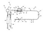
- FIG. 1is a schematic diagram of a guidewire occlusion system in accordance with the present invention and operating in an evacuation mode.
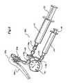
- FIG. 2is a schematic diagram of the guidewire occlusion system shown in FIG. 1 operating in an inflation mode.
- FIG. 3 ais a side view of the guidewire assembly shown in FIG. 1 ; and FIG. 3 b is an enlarged view of the portion of FIG. 3 a delineated by the circle 3 b.
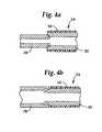
- FIGS. 4 a and 4 bare fragmentary cross-sectional views of different manners of joining the extended sealable section to the main body portion at the proximal portion of the guidewire assembly of FIG. 3 a.
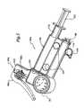
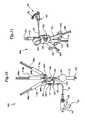
- FIGS. 5-7are perspective views of three alternate embodiments of gas inflation/evacuation systems and the sealing systems used therewith.
- FIG. 8is an exploded view of the gas inflation/evacuation system of the alternate embodiment shown in FIG. 7 and the associated sealing system.
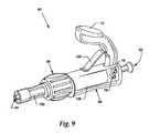
- FIG. 9is a perspective view of the sealing system illustrated with the alternate embodiment shown in FIG. 7 .
- FIG. 10is a top view of a preferred embodiment of a gas inflation/evacuation system and sealing system used in the present invention.
- FIG. 11is a perspective view of another alternate embodiment of a gas inflation/evacuation system and sealing system.
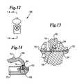
- FIG. 12is an end view of a crimping mechanism.
- FIGS. 13 and 14are two sectional views of the crimping mechanism of FIG. 12 , FIG. 14 being a view taken along the line 14 — 14 of FIG. 12 , and FIG. 13 being a magnification of the portion of FIG. 14 indicated by the dashed circle.
- FIG. 15is a cross-sectional view of an alternate embodiment of a sealing system showing one embodiment of a plugging mechanism.
- FIGS. 16 and 17are schematic views relating to assembling and packaging the guidewire occlusion system, FIG. 16 showing equipment including a sealed chamber for use in assembling and packaging, and FIG. 17 showing a side view of a biocompatible packaging.
- the guidewire occlusion system 20includes a guidewire assembly 22 , a sealing system 60 , and a gas inflation/evacuation system 80 .
- Guidewire assembly 22is a tubular member that includes a proximal portion 24 and a distal portion 26 .
- proximal and distalwill be used with reference to an operator, such that a distal portion of the guidewire assembly 22 , for example, is the portion first inserted into a blood vessel, and the proximal portion remains exterior to the patient and is therefore closer to the operator.
- An extended sealable section 28is provided proximate the proximal portion 24 of guidewire assembly 22 .
- the extended sealable section 28is an extended crimpable section comprised of a tubular segment having an outer diameter smaller than an outer diameter of a main body portion 30 of guidewire assembly 22 .
- an occlusive balloon 32is located along the distal portion 26 of guidewire assembly 22 .
- the occlusive balloon 32is fluidly connected via a lumen 34 to the proximal end 36 of guidewire assembly 22 , with channels or holes 35 allowing for fluid communication between lumen 34 and occlusive balloon 32 .
- a flexible tip 38is positioned at the distal end 40 of distal portion 26 of the guidewire assembly 22 .
- distal portion 26 of guidewire assembly 22includes a tapered portion 42 to increase the flexibility and transition properties of the distal portion 26 of guidewire assembly 22 .
- sealing system 60is implemented as part of a handheld apparatus that also includes gas inflation/evacuation system 80 .
- sealing system 60may be a handheld unit completely separate from the gas inflation/evacuation system 80 .
- Sealing system 60includes a first aperture 62 into which the proximal end 36 of guidewire assembly 22 is insertable so as to operably position at least a portion of extended sealable section 28 in relation to sealing system 60 .
- Sealing system 60further includes a second aperture 64 that is fluidly connectible to gas inflation/evacuation system 80 .
- the sealing system 60includes means for selectively sealing the extended sealable section which in the preferred embodiment comprises a crimping mechanism 66 and a sealing mechanism 68 .
- a passageway 70is defined from first aperture 62 to second aperture 64 and extends through both crimping mechanism 66 and sealing mechanism 68 .
- the crimping mechanism 66comprises a handle 72 that actuates a pivotable cam arrangement 74 that crimps and then severs the extended sealable section 28 between a pair of rollers 76 , 78 by mechanically flattening and pinching the extended sealable section 28 to the point of breaking.
- the sealing mechanism 68has a rotatable hemostatic valve positioned proximal to the crimping mechanism 66 along passageway 70 .
- crimping mechanism 66 and sealing mechanism 68are arranged coaxially with each other along a straight portion of passageway 70 .
- the relative distance between the engaging portions of sealing mechanism 68 and crimping mechanism 66 in this embodimenteffectively defines the relative distances between a plurality of locations along extended sealable section 28 at which an airtight seal can be created, as shown in FIGS. 1-2 .
- the length of the extended sealable section 28should be greater than at least twice the distance between crimping mechanism 66 and sealing mechanism 68 .
- the gas inflation/evacuation system 80is connected via conduit 82 to the second aperture 64 of the sealing system 60 .
- the gas inflation/evacuation system 80preferably includes a valve arrangement 84 that selectively couples one of an evacuation system which includes means for evacuating the guidewire assembly and an inflation system which includes means for introducing a gas into the guidewire assembly to the conduit 82 .
- the evacuation systemincludes an evacuation syringe 86 which is used to evacuate the guidewire assembly 22 , passageway 70 , and conduit 82 .
- the inflation systemincludes an inflation syringe 88 which contains a volume of a gas sufficient to inflate the occlusive balloon 32 a plurality of times.
- a pressure gauge 90can be associated with the inflation syringe 88 .
- the gasis a biocompatible gas such as carbon dioxide.
- Other biocompatible gasses that may be utilized with the present inventioninclude oxygen, nitrogen, and nitrous oxide. While non-biocompatible gasses could be used, biocompatible gasses that are soluble in blood are preferred so as not to cause gas embolization in the event of a leak in the gas inflation/evacuation system.
- the biocompatible gasalso has a good driving gradient in addition to being soluble, in that the biocompatible gas will effectively go into a solution, in this case blood, better than ambient air.
- low viscosity biocompatible liquids or foamsalso may be used for inflation provided the surface tension of the fluid is sufficient to permit the rapid inflation and deflation contemplated by the present invention.
- the evacuation portion of the gas inflation/evacuation system 80would not be necessary, as the evacuation portion of the gas inflation/evacuation system 80 is intended for safety purposes to ensure that air within the guidewire assembly 22 and sealing system 60 is not introduced into the blood stream in the event of a failure, leakage or bursting of any component.
- guidewire assembly 22is constructed as described in further detail in the previously identified co-pending application Ser. No. 10/012,891 entitled “Guidewire Assembly Having Occlusive Device And Repeatably Crimpable Proximal End.”
- the main body portion 30is formed of a primary stainless steel hypotube having an outer diameter of 0.013 inch and an inner diameter of 0.007 inch. To accomplish passive deflation in the desired time of less than one minute when the extended sealable section 28 is cut, it is preferable that the main body portion 30 have an inner diameter of at least 0.002 inch.
- the extended sealable section 28 of guidewire assembly 22is comprised of a crimp tube also formed of stainless steel and having an outer diameter of 0.009 inch to 0.015 inch and an inner diameter of at least 0.002 inch and preferably about 0.005 inch.
- the extended sealable section 28is preferably a separate piece secured to the proximal portion 24 by a laser weld 44 (see FIGS. 1 , 2 and 3 a ) of sufficient strength.
- the extended sealable section 28may be formed by centerless grinding or reducing the outer diameter of a portion of the proximal portion 24 of the main body portion 30 of guidewire assembly 22 .
- the extended sealable sectionmay be a modified, treated or otherwise fabricated portion of the proximal portion 24 of the main body portion 30 of guidewire assembly 22 that is suitable for the particular sealing technique to be used.
- the distal end of the extended sealable section 28is preferably centerless ground and press fit within a chamfered proximal end of the main body portion 30 .
- a chamfered crimp arrangementcould be used.
- a separate joining/crimping tube or other tubular joining arrangementscould be used.
- a protective polymer coating 56 of polytetrafluoroethylene (PTFE) or a hydrophilic coatingis applied by any of a number of known techniques such that the coating 56 surrounds the main body portion 30 .
- the protective polymer coating 56is preferably about 0.0004+/ ⁇ 0.0003 inch thick such that the effective outer diameter of the main body portion 30 of guidewire assembly 22 is 0.0132-0.0144 inch.
- the extended sealable section 28can be made of any material that when deformed and severed retains that deformation so as to form an airtight seal. When crimped and severed, it is preferable that the extended sealable section 28 not present a sharp, rigid point that is capable of piercing a gloved hand. It has been found that as long as the preferred embodiment is not gripped within less than one inch of the proximal end of the extended sealable section 28 , the severed proximal end of the extended sealable section 28 does not penetrate a standard surgical glove. In addition, the extended sealable section 28 must have sufficient strength in terms of high tensile and kink resistance to permit catheter devices to repeatedly pass over the extended sealable section 28 .
- the main body portion 30is preferably secured to the distal portion 26 using a Ni—Ti or stainless steel sleeve 46 laser welded to the main body portion 30 at laser weld 48 and crimped to the distal portion 26 at crimp 50 .
- the distal portion 26is preferably formed of a Ni—Ti alloy having an inner diameter of 0.0045 inch and an outer diameter that ranges from 0.014 inch to 0.0075 inch to form tapered portion 42 , preferably formed by a centerless grinding process.
- the distal portionincludes a pair of coil sections, proximal tip coil 52 and distal tip coil 54 , that are longitudinally spaced apart and adjacent to the holes 35 and that assist in providing a better surface for bonding the occlusive balloon 32 to the distal portion 26 .
- This arrangementalso tends to increase the visibility of the location of the occlusive balloon 32 under fluoroscopy, as the occlusive balloon 32 filled with a biocompatible gas will be radiotranslucent when compared to the two coils 52 and 54 .
- a platinum markerbandcould be located around the distal portion 26 just proximal to the occlusive balloon 32 to serve as a radiopaque/MRI marker.
- the flexible tip 38is a coiled tip attached to distal portion 26 distal to occlusive balloon 32 , preferably by a crimp.
- a sleevecould be welded to the flexible tip 38 , and the tapered portion 42 could then be inserted into this sleeve and crimped.
- any number of other alloys or polymer materials and attachment techniquescould be used in the construction of the guidewire assembly 22 , provided the materials offer the flexibility and torque characteristics required for a guidewire and the attachment techniques are sufficiently strong enough and capable of making an airtight seal.
- These materialsinclude, but are not limited to, Ni—Ti, 17-7 stainless steel, 304 stainless steel, cobalt superalloys, or other polymer, braided or alloy materials.
- the attachment techniques for constructing guidewire assembly 22include, but are not limited to, welding, mechanical fits, adhesives, sleeve arrangements, or any combination thereof.
- the occlusive balloon 32may be made of any number of polymer or rubber materials.
- the occlusive balloonis preinflated to prestretch it so that expansion is more linear with pressure.
- the pressure supplied by gas inflation/evacuation system 80is designed to stay well within the elastic limit of the occlusive balloon 32 .
- a two-layer occlusive balloon arrangement, adding gas and/or liquid between balloon layers,may be used in an alternate embodiment to increase visibility of the distal end 40 of the distal portion 26 of the guidewire assembly 22 under fluoroscopy.
- valve arrangement 84is set for evacuation. Evacuation syringe plunger 92 of evacuation syringe 86 is slidably withdrawn removing any air from guidewire assembly 22 . Valve arrangement 84 is then set for inflation.
- Inflation syringe plunger 94 of inflation syringe 88is slidably advanced inserting a volume of an inert gas into guidewire assembly 22 .
- the inert gasinflates occlusive balloon 32 as shown in FIG. 2 .
- the medical personnelmonitor pressure gauge 90 to ensure that the inflation pressure does not exceed the burst rating of the occlusive balloon 32 and to gauge the relative size of the occlusive balloon 32 as it is inflated.
- crimping mechanism 66is employed to crimp the extended sealable section 28 of guidewire assembly 22 , thereby sealing the guidewire assembly 22 to maintain the occlusive balloon 32 in an inflated state.
- Sealing mechanism 68is released and the extended sealable section 28 is removed from first aperture 62 such that the proximal portion 24 of the guidewire assembly 22 is free of mechanical or other obstructions and can function as a conventional guidewire.
- the extended sealable section 28is cut using a medical scissors or the like distal to the existing crimp in the extended sealable section 28 .
- the medical personneldeem reinflation of the occlusive balloon 32 to be necessary, the extended sealable section 28 of the proximal portion 24 is reinserted into first aperture 62 . Sealing mechanism 68 is then reactivated and the evacuation/inflation process can be repeated.
- a crimping handle 72may also be provided with a separate severing arrangement to cut the extended sealable section 28 .
- extended sealable section 28may be scored or otherwise weakened in selected locations to assist in crimping or severing, including severing by repeated bending back and forth at one of the scored locations.
- the extended sealable section 28could be broken off rather than sheared by using a brittle metal for the extended sealable section that aids in the severing of the extended sealable section 28 .
- FIG. 5shows an alternative unitized gas inflation/evacuation system 80 a and also an alternative sealing system 60 a .
- Assembly body 96contains individual inflation syringe 114 with inflation syringe plunger 98 and individual evacuation syringe 112 with evacuation syringe plunger 100 .
- Assembly body 96contains pressure gauge 90 .
- Attached to assembly body 96is support structure 102 which supports a sealing system 60 a that includes crimping mechanism 66 a and sealing mechanism 68 a .
- Valve arrangement 84is mounted on the surface of assembly body 96 .
- Assembly body 96contains two fingergrip bores 104 . Attached to assembly body 96 is fingergrip 106 .
- the assembly body 96is constructed of a suitable inert plastic polymer, although any polymer material used in construction of medical devices could be used.
- the assembly body 96can be constructed of suitable metal alloys or even of tempered glass or any combination thereof.
- FIG. 6shows an alternative gas inflation/evacuation system 80 b in use with sealing system 60 a .
- Valve arrangement 108has three interconnect fittings 110 a , 110 b and 110 c .
- Attached to interconnect fitting 110 ais evacuation syringe 112 .
- Evacuation syringe 112includes evacuation syringe plunger 100 .
- Attached to interconnect fitting 110 bis pressure gauge 90 .
- Pressure gauge 90is fluidly interconnected to inflation syringe 114 .
- Inflation syringe 114includes inflation syringe plunger 98 .
- Attached to the interconnect fitting 110 cis sealing system 60 a comprised of crimping mechanism 66 a and sealing mechanism 68 a .
- one-way check valves 111 and 113are respectively connected between interconnect fitting 110 a and evacuation syringe 112 between interconnect fitting 110 b and inflation syringe 114 as a safety measure to ensure only one-way flow of the gas within the gas inflation/evacuation system 80 b .
- One-way check valve 113ensures that only the carbon dioxide gas is delivered out of the gas inflation/evacuation system and prevents any reinfusion of air that has been evacuated from the gas inflation/evacuation system.
- FIGS. 7 and 8show an alternative gas inflation/evacuation system 80 c with sealing system 60 .
- Assembly body 118contains inflation syringe 114 and evacuation syringe 112 .
- Inflation syringe 114includes inflation syringe plunger 98 .
- Evacuation syringe 112includes evacuation syringe plunger 100 .
- Knob 120 connected to valve arrangement 108is mounted on the exterior of assembly body 118 .
- Pressure gauge 90is contained within assembly body 118 .
- Assembly body 118contains fingergrips 106 .
- Conduit 122is attached to assembly body 118 .
- sealing system 60is comprised of crimping mechanism 66 and sealing mechanism 68 .
- FIG. 9shows an embodiment of the sealing system.
- sealing system 60which is comprised of sealing mechanism 68 and crimping mechanism 66 .
- Crimping mechanism 66is comprised of crimp body 126 , handle 72 , handle return 128 , and first aperture 62 .
- Sealing mechanism 68is comprised of sealing body 132 and second aperture 64 .
- Sealing system 60has a passageway 70 (see FIGS. 1 and 2 ) fluidly interconnecting first aperture 62 and second aperture 64 .
- FIG. 10shows an alternative gas inflation/evacuation system 80 d coupled to sealing system 60 .
- Valve arrangement 108has a coupling 141 connected to conduit 82 and a port 138 that is attached via one-way check valve 111 and hose 140 to evacuation syringe 112 .
- Attached to an interconnect fitting 139 of the valve arrangement 108is inflation manifold 142 .
- Inflation manifold 142is connected to connector 146 and pressure gauge 90 .
- Inflation manifold 142has three check valves 144 a , 144 b and 144 c .
- Check valves 144 a , 144 b and 144 care connected to respective inflation syringes 114 a , 114 b and 114 c which have respective inflation syringe plungers 98 a , 98 b , and 98 c .
- evacuation syringe 112is mounted behind pressure gauge 90 .
- the distal end of conduit 82is connected to sealing system 60 .
- Sealing system 60is comprised of sealing mechanism 68 and crimping mechanism 66 .
- FIG. 11shows an alternative gas inflation/evacuation system 80 e that is similar to the gas inflation/evacuation system 80 d shown in FIG. 10 except that the components are arranged in a common housing 150 .
- Common housing 150has internal sealed channels that fluidly interconnect via valve arrangement 108 to evacuation syringe 112 and to inflation syringes 114 a , 114 b and 114 c and pressure gauge 90 .
- Common housing 150has structure 152 that defines chambers for the three inflation syringes 114 a , 114 b and 114 c .
- Common housing 150also includes structure defining external fingergrips 106 and internal fingergrips 154 between adjacent portions of structure 152 .
- Common housing 150also contains structure for integrating evacuation syringe 112 and pressure gauge 90 as part of the common housing 150 .
- An external knob 156connects to the valve arrangement 108 .
- FIGS. 10 and 11allow for effective pressurization of occlusive balloon 32 at less than 2 atmospheres while reducing the total volume of gas that might be introduced into a patient in the event of a leak in the guidewire occlusion system 20 .
- the total amount of pressurized gas in a single inflation syringesuch as 88 in FIGS. 1 and 2 or 114 in FIGS. 5-8 can be significant. If a leak were to occur, the entire contents of a single inflation syringe would be susceptible to that leak.
- these alternate embodimentsprovide a simple way of decreasing the total amount of pressurized gas that might be introduced into a patient in the event of a leakage in the guidewire occlusion system 20 .
- a similar resultcould be achieved by manually attaching separate inflation syringes 114 a , 114 b , 114 c and an evacuation syringe 112 directly to the sealing system 60 by way of a Luer lock or the like. While such an embodiment would not be as quick or convenient as the preferred embodiment, such alternative would eliminate the volume of gas required for the conduit 82 and within common housing 150 , as well as the need for a valve arrangement 108 .
- the sealing systemcould include means for selectively sealing involving techniques other than crimping to accomplish multiple airtight seals along the course of the extended sealable section 28 .
- One alternate embodiment, as portrayed in FIG. 15would involve the insertion of some form of sealant material 158 into the proximal end of the extended sealable section 28 , such as wax, plastic, polymer or metal inserts or plugs.
- Conduit 82is attached to plugging mechanism 162 through the conduit aperture 160 .
- sealant material 158is confined by sealant confinement layer 164 residing within plugging mechanism 162 .
- sealant material 158is a wax or gel that is flowable at higher temperatures and might be melted during sterilization of the sealing system.
- Sealant confinement layer 164is a foil layer or thin layer of non-meltable material capable of confining a flowable material during any sterilization process or exposure to higher temperature.
- the proximal end of extended sealable section 28is inserted through first aperture 62 until it is past operational O-ring 166 or some other form of sealable/deformable material such as a silicone puncture seal or similar membrane seal.
- the extended sealable section 28is further inserted past a sealant O-ring 168 , then through sealant confinement layer 164 , and finally into sealant material 158 .
- Sealant material 158is deposited in the proximal end of extended sealable section 28 , thus preventing the guidewire assembly 22 from being evacuated.
- Extended sealable section 28can then be slidably withdrawn through the sealant O-ring 168 , through the operational O-ring 166 , and through the first aperture 62 , thereby effectively disengaging the guidewire assembly 22 from the plugging mechanism 162 .
- the O-rings 166 and 168serve as wiping structures to remove excess sealant material from the outside of the extended sealable section 28 .
- Other alternate embodimentsinvolve heating the extended sealable section 28 when it is formed of metal or polymer material so as to create a constriction, or applying electrical or magnetic energy to arc or weld material within the extended sealable section 28 to create a constriction.
- the equivalent of a spot weldercould be used in place of the crimping mechanism 66 to accomplish the same purpose of sealing, and then severing the extended sealable section 28 .
- Alternative embodimentscould use other sealing techniques to seal the guidewire assembly 22 . These methods could include, but are not limited to, ones utilizing a heat source to melt the extended sealable section, ones using a heat source to apply a glue or gel, methods involving insertion of a plug material, methods using magnetics to manipulate a sealing material, or methods utilizing small occlusive devices.
- the extended sealable section 28is of sufficient length to allow deflation through the shearing, breaking or opening of the extended sealable section 28 distal to the sealant material 158 located in the proximal end of the extended sealable section 28 .
- the guidewire assembly 22can be coupled to the gas inflation/evacuation system 80 (or 80 a - 80 e ) multiple times, allowing the occlusive balloon 32 to be inflated and deflated multiple times.
- Other embodimentswill use methods of deflation including melting the sealant material 158 , removing a plug of sealant material 158 , and various other methods not requiring the extended sealable section 28 to be sheared.
- the guidewire occlusion system 20is preferably pre-assembled and packaged in an environment consisting of an appropriate biocompatible gas.
- FIGS. 16 and 17show equipment with which the guidewire occlusion system 20 is assembled and packaged.
- the guidewire occlusion system 20is assembled and packaged in a sealed chamber 170 .
- Sealed chamber 170is equipped with a venting duct 171 , sealed handling ports 173 , and an atmosphere control system 175 . Sealed chamber 170 has an atmosphere composed of biocompatible gas.
- the guidewire assembly 22 , sealing system 60 (or 60 a ), and gas inflation/evacuation system 80 (or 80 a - 80 e )are assembled to form the guidewire occlusion system 20 and are placed into biocompatible packaging 174 .
- Biocompatible packaging 174is hermetically sealed so that the internal volume of both biocompatible packaging 174 and guidewire occlusion system 20 is composed solely of biocompatible gas.
- Valve arrangement 84(or 108 ) is then adjusted to the inflation position and inflation syringe plunger 94 (or 98 , 98 a , 98 b , 98 c ) is slidably inserted causing occlusive balloon 32 to inflate.
- Severing of the extended sealable section 28serves as an immediate verification of the creation of an effective seal.
- Sealing mechanism 68(or 68 a ) can be released and guidewire assembly 22 can be completely removed from the sealing system 60 (or 60 a ) allowing the occlusive balloon 32 to remain inflated while occlusive substance treatment occurs.
- the extended sealable section 28can be sheared or broken off, resulting in the deflation of the occlusive balloon 32 .
- guidewire assembly 22can be removed from the vessel lumen. If additional treatment is required, extended sealable section 28 can be reattached to sealing system 60 (or 60 a ) through first aperture 62 . Sealing mechanism 68 (or 68 a ) can be retightened and the evacuation/inflation process can be repeated.
- the guidewire assembly 22is utilized as the guidewire for an atherectomy or thrombectomy procedure of the type described in U.S. Pat. Nos. 5,370,609 or 5,496,267, the disclosures of both of which are hereby incorporated by reference.
- the guidewire assembly 22is introduced into the patient, the occlusive balloon 32 is inflated, and then the atherectomy or thrombectomy catheter arrangement is slid over the proximal end 36 of the guidewire assembly 22 and advanced until it is proximate and proximal to the location of the occlusive balloon.
- the procedureis performed for a time period consistent with the desired maximum length for blockage of the particular vessel, typically within 5 minutes, at which time the extended sealable section 28 of the guidewire assembly 22 may be severed to deflate the occlusive balloon 32 , thereby reestablishing blood flow within the vessel.
- the catheter arrangementmay be removed from the vessel or left in place.
- an evacuation of any plaque material or other debris dislodged by the therapyis accomplished before deflation of the occlusive balloon 32 .
- the occlusive balloon 32is reinflated prior to reinitiation of the procedure.
- Rapid inflation and deflation of an occlusive balloonis the key to a successful occlusion device.
- the viscosity of the inflation fluid and resistance through the evacuation/inflation lumensdictate the effective speed of inflation and deflation.
- the present inventionis able to increase the amount of resistance through the evacuation/inflation lumen that can be overcome. This results in being able to use a smaller inner diameter tube for the evacuation/inflation lumen which allows for a significant increase in the structural robustness of the guidewire assembly while maintaining the desired inflation and deflation properties.
- the increase in allowable resistancealso allows for the use of longer guidewire assemblies, specifically guidewire assemblies that are a more typical exchange length.
Landscapes
- Health & Medical Sciences (AREA)
- Life Sciences & Earth Sciences (AREA)
- Heart & Thoracic Surgery (AREA)
- Public Health (AREA)
- Engineering & Computer Science (AREA)
- Anesthesiology (AREA)
- Biomedical Technology (AREA)
- Hematology (AREA)
- Animal Behavior & Ethology (AREA)
- General Health & Medical Sciences (AREA)
- Veterinary Medicine (AREA)
- Pulmonology (AREA)
- Biophysics (AREA)
- Child & Adolescent Psychology (AREA)
- Vascular Medicine (AREA)
- Surgical Instruments (AREA)
Abstract
Description
- 20 guidewire occlusion system
- 22 guidewire assembly
- 24 proximal portion
- 26 distal portion
- 28 extended sealable section
- 30 main body portion
- 32 occlusive balloon
- 34 lumen
- 35 channel or hole
- 36 proximal end
- 38 flexible tip
- 40 distal end
- 42 tapered portion
- 44 laser weld
- 46 Ni—Ti or stainless steel sleeve
- 48 laser weld
- 50 crimp
- 52 proximal tip coil
- 54 distal tip coil
- 56 protective polymer coating
- 60 sealing system
- 60asealing system
- 62 first aperture
- 64 second aperture
- 66 crimping mechanism
- 66acrimping mechanism
- 68 sealing mechanism
- 68asealing mechanism
- 70 passageway
- 72 handle
- 74 pivotable cam arrangement
- 76 roller
- 78 roller
- 80 gas inflation/evacuation system
- 80a-egas inflation/evacuation systems
- 82 conduit
- 84 valve arrangement
- 86 evacuation syringe
- 88 inflation syringe
- 90 pressure gauge
- 92 evacuation syringe plunger
- 94 inflation syringe plunger
- 96 assembly body
- 98 inflation syringe plunger
- 98a-cinflation syringe plungers
- 100 evacuation syringe plunger
- 102 support structure
- 104 fingergrip bore
- 106 fingergrip
- 108 valve arrangement
- 110a-cinterconnect fittings
- 112 evacuation syringe
- 113 one-way check valve
- 114 inflation syringe
- 114a-cinflation syringes
- 118 assembly body
- 120 knob
- 122 conduit
- 126 crimp body
- 128 handle return
- 132 sealing body
- 138 port
- 139 interconnect fitting
- 140 hose
- 141 coupling
- 144a-ccheck valves
- 146 connector
- 150 common housing
- 152 structure
- 156 knob
- 158 sealant material
- 160 conduit aperture
- 162 plugging mechanism
- 164 sealant containment layer
- 166 O-ring
- 168 O-ring
- 170 sealed chamber
- 171 venting duct
- 173 sealed handling port
- 174 biocompatible packaging
- 175 atmosphere control system
Claims (33)
Priority Applications (10)
| Application Number | Priority Date | Filing Date | Title |
|---|---|---|---|
| US10/012,903US6932828B2 (en) | 2001-11-06 | 2001-11-06 | Guidewire occlusion system utilizing repeatably inflatable gas-filled occlusive device |
| JP2003541913AJP2005508230A (en) | 2001-11-06 | 2002-11-06 | Guidewire expansion system employing a gas-filled expansion element that can be expanded repeatedly |
| DE60233351TDE60233351D1 (en) | 2001-11-06 | 2002-11-06 | GUIDING WIRE OCCLUSION SYSTEM WITH REPLAY OF FILLABLE GAS-FILLED OCCLUSION DEVICE |
| PCT/US2002/035633WO2003039624A2 (en) | 2001-11-06 | 2002-11-06 | Guidewire occlusion system utilizing repeatably inflatable gas-filled occlusive device |
| EP02784406AEP1467778B1 (en) | 2001-11-06 | 2002-11-06 | Guidewire occlusion system utilizing repeatably inflatable gas-filled occlusive device |
| AT02784406TATE439158T1 (en) | 2001-11-06 | 2002-11-06 | GUIDEWIRE OCCLUSION SYSTEM WITH REPEATABLE GAS-FILLED OCCLUSION DEVICE |
| US10/838,468US20050182437A1 (en) | 2001-11-06 | 2004-05-04 | Guidewire assembly including a repeatably inflatable occlusive balloon on a guidewire ensheathed with a spiral coil |
| US10/838,464US7220243B2 (en) | 2001-11-06 | 2004-05-04 | Gas inflation/evacuation system and sealing system incorporating a compression sealing mechanism for guidewire assembly having occlusive device |
| US11/009,810US20060064071A1 (en) | 2001-11-06 | 2004-12-10 | Gas inflation/evacuation system incorporating a reservoir and removably attached sealing system for a guidewire assembly having an occlusive device |
| US11/654,741US7334681B2 (en) | 2001-11-06 | 2007-01-18 | Packaging system with oxygen sensor for gas inflation/evacuation system and sealing system |
Applications Claiming Priority (1)
| Application Number | Priority Date | Filing Date | Title |
|---|---|---|---|
| US10/012,903US6932828B2 (en) | 2001-11-06 | 2001-11-06 | Guidewire occlusion system utilizing repeatably inflatable gas-filled occlusive device |
Related Parent Applications (1)
| Application Number | Title | Priority Date | Filing Date |
|---|---|---|---|
| US10/012,891Continuation-In-PartUS7169161B2 (en) | 2001-11-06 | 2001-11-06 | Guidewire having occlusive device and repeatably crimpable proximal end |
Related Child Applications (3)
| Application Number | Title | Priority Date | Filing Date |
|---|---|---|---|
| US10/007,788Continuation-In-PartUS6942678B2 (en) | 2001-11-06 | 2001-11-06 | Gas inflation/evacuation system and sealing system for guidewire assembly having occlusive device |
| US10/838,464Continuation-In-PartUS7220243B2 (en) | 2001-11-06 | 2004-05-04 | Gas inflation/evacuation system and sealing system incorporating a compression sealing mechanism for guidewire assembly having occlusive device |
| US10/838,468Continuation-In-PartUS20050182437A1 (en) | 2001-11-06 | 2004-05-04 | Guidewire assembly including a repeatably inflatable occlusive balloon on a guidewire ensheathed with a spiral coil |
Publications (2)
| Publication Number | Publication Date |
|---|---|
| US20030088263A1 US20030088263A1 (en) | 2003-05-08 |
| US6932828B2true US6932828B2 (en) | 2005-08-23 |
Family
ID=21757293
Family Applications (1)
| Application Number | Title | Priority Date | Filing Date |
|---|---|---|---|
| US10/012,903Expired - Fee RelatedUS6932828B2 (en) | 2001-11-06 | 2001-11-06 | Guidewire occlusion system utilizing repeatably inflatable gas-filled occlusive device |
Country Status (1)
| Country | Link |
|---|---|
| US (1) | US6932828B2 (en) |
Cited By (19)
| Publication number | Priority date | Publication date | Assignee | Title |
|---|---|---|---|---|
| US20030088262A1 (en)* | 2001-11-06 | 2003-05-08 | Possis Medical,Inc | Guidewire having occlusive device and repeatably crimpable proximal end |
| US20050020998A1 (en)* | 2001-11-06 | 2005-01-27 | Bonnette Michael J. | Gas inflation/evacuation system and sealing system incorporating a compression sealing mechanism for guidewire assembly having occlusive device |
| US20050182437A1 (en)* | 2001-11-06 | 2005-08-18 | Bonnette Michael J. | Guidewire assembly including a repeatably inflatable occlusive balloon on a guidewire ensheathed with a spiral coil |
| US20050228314A1 (en)* | 2002-08-26 | 2005-10-13 | Mark Eberhart | Guide-wire mounted balloon modulation device and methods of use |
| US20060064071A1 (en)* | 2001-11-06 | 2006-03-23 | Possis Medical, Inc. | Gas inflation/evacuation system incorporating a reservoir and removably attached sealing system for a guidewire assembly having an occlusive device |
| US20080275397A1 (en)* | 2004-08-31 | 2008-11-06 | Bonnette Michael J | Low pierce force needle port |
| US20080312671A1 (en)* | 2007-06-12 | 2008-12-18 | Possis Medical, Inc. | Infusion flow guidewire system |
| US7615031B2 (en) | 2005-09-01 | 2009-11-10 | Medrad, Inc. | Gas inflation/evacuation system incorporating a multiple element valved guidewire assembly having an occlusive device |
| US8157766B2 (en) | 2005-09-01 | 2012-04-17 | Medrad, Inc. | Torqueable kink-resistant guidewire |
| US9238122B2 (en) | 2012-01-26 | 2016-01-19 | Covidien Lp | Thrombectomy catheter systems |
| US9238119B2 (en) | 2010-08-12 | 2016-01-19 | Boston Scientific Limited | Infusion flow system and fluid coupling |
| US9592068B2 (en) | 2013-03-15 | 2017-03-14 | Insera Therapeutics, Inc. | Free end vascular treatment systems |
| US9750524B2 (en) | 2013-03-15 | 2017-09-05 | Insera Therapeutics, Inc. | Shape-set textile structure based mechanical thrombectomy systems |
| US9833251B2 (en) | 2013-03-15 | 2017-12-05 | Insera Therapeutics, Inc. | Variably bulbous vascular treatment devices |
| US9901435B2 (en) | 2013-03-15 | 2018-02-27 | Insera Therapeutics, Inc. | Longitudinally variable vascular treatment devices |
| US10390926B2 (en) | 2013-07-29 | 2019-08-27 | Insera Therapeutics, Inc. | Aspiration devices and methods |
| US10463232B2 (en) | 2010-10-18 | 2019-11-05 | Sanovas Intellectual Property, Llc | Anchored guidewire |
| US11185334B2 (en) | 2019-03-28 | 2021-11-30 | DePuy Synthes Products, Inc. | Single lumen reduced profile occlusion balloon catheter |
| US11602617B2 (en) | 2019-04-18 | 2023-03-14 | Michael Bonnette | Pumpless thrombectomy system |
Families Citing this family (9)
| Publication number | Priority date | Publication date | Assignee | Title |
|---|---|---|---|---|
| US8267871B2 (en)* | 2002-08-26 | 2012-09-18 | Kensey Nash Corporation | Guidewire mounted balloon modulation device and methods of use |
| US7004914B2 (en)* | 2002-08-26 | 2006-02-28 | Kensey Nash Corporation | Crimp and cut tool for sealing and unsealing guide wires and tubular instruments |
| US7803124B2 (en)* | 2002-08-26 | 2010-09-28 | Kensey Nash Corporation | Guidewire mounted balloon modulation device and methods of use |
| WO2005053529A1 (en) | 2003-11-21 | 2005-06-16 | Radi Medical Systems Ab | Sensor and guide wire assembly |
| WO2006091678A1 (en)* | 2005-02-24 | 2006-08-31 | Boston Scientific Santa Rosa Corporation | Constant force material delivery system and method |
| US8221348B2 (en)* | 2005-07-07 | 2012-07-17 | St. Jude Medical, Cardiology Division, Inc. | Embolic protection device and methods of use |
| US20080097294A1 (en)* | 2006-02-21 | 2008-04-24 | Possis Medical, Inc. | Occlusive guidewire system having an ergonomic handheld control mechanism prepackaged in a pressurized gaseous environment and a compatible prepackaged torqueable kink-resistant guidewire with distal occlusive balloon |
| WO2017180640A1 (en) | 2016-04-12 | 2017-10-19 | Safe Medical Design, Inc. | Safe urinary catheter and manufacturing method |
| US11033721B2 (en)* | 2018-06-22 | 2021-06-15 | Acclarent, Inc. | Guidewire for dilating eustachian tube via middle ear |
Citations (58)
| Publication number | Priority date | Publication date | Assignee | Title |
|---|---|---|---|---|
| US4332254A (en)* | 1980-11-17 | 1982-06-01 | Advanced Catheter Systems, Inc. | System for filling and inflating and deflating a vascular dilating cathether assembly |
| US4573966A (en) | 1981-11-24 | 1986-03-04 | Schneider Medintag Ag | Method and apparatus for removing and/or enlarging constricted areas in vessels conducting body fluids |
| US4573470A (en) | 1984-05-30 | 1986-03-04 | Advanced Cardiovascular Systems, Inc. | Low-profile steerable intraoperative balloon dilitation catheter |
| US4636195A (en) | 1982-04-02 | 1987-01-13 | Harvey Wolinsky | Method and apparatus for removing arterial constriction |
| US4646719A (en) | 1984-06-11 | 1987-03-03 | Aries Medical Incorporated | Intra-aortic balloon catheter having flexible torque transmitting tube |
| US4651738A (en)* | 1985-08-02 | 1987-03-24 | Baylor College Of Medicine | Method and device for performing transluminal angioplasty |
| US4733652A (en) | 1985-12-31 | 1988-03-29 | Aisin Seiki Kabushiki Kaisha | Intra-aortic balloon |
| US4838268A (en) | 1988-03-07 | 1989-06-13 | Scimed Life Systems, Inc. | Non-over-the wire balloon catheter |
| US4865587A (en) | 1987-01-14 | 1989-09-12 | Walling Peter T | Syringe and catheter apparatus |
| US5059178A (en) | 1988-08-03 | 1991-10-22 | Ya Wang D | Method of percutaneously removing a thrombus from a blood vessel by using catheters and system for removing a thrombus from a blood vessel by using catheters |
| US5059176A (en) | 1989-12-21 | 1991-10-22 | Winters R Edward | Vascular system steerable guidewire with inflatable balloon |
| US5106363A (en)* | 1988-10-11 | 1992-04-21 | Terumo Kabushiki Kaisha | Blood perfusion system and tube used therein |
| US5135482A (en) | 1985-12-31 | 1992-08-04 | Arnold Neracher | Hydrodynamic device for the elimination of an organic deposit obstructing a vessel of a human body |
| US5167239A (en) | 1991-05-30 | 1992-12-01 | Endomedix Corporation | Anchorable guidewire |
| US5171221A (en) | 1991-02-05 | 1992-12-15 | Target Therapeutics | Single lumen low profile valved balloon catheter |
| US5195955A (en) | 1989-11-14 | 1993-03-23 | Don Michael T Anthony | Device for removal of embolic debris |
| US5209727A (en) | 1992-01-29 | 1993-05-11 | Interventional Technologies, Inc. | Guide wire with integral angioplasty balloon |
| US5320604A (en) | 1991-04-24 | 1994-06-14 | Baxter International Inc. | Low-profile single-lumen dual-balloon catheter with integrated guide wire for embolectomy dilatation/occlusion and delivery of treatment fluid |
| US5324260A (en)* | 1992-04-27 | 1994-06-28 | Minnesota Mining And Manufacturing Company | Retrograde coronary sinus catheter |
| US5334153A (en)* | 1992-10-07 | 1994-08-02 | C. R. Bard, Inc. | Catheter purge apparatus and method of use |
| US5380284A (en) | 1993-08-13 | 1995-01-10 | Don Michael; T. Anthony | Obstruction dissolution catheter with variably expanding blocking balloons and method of use |
| US5520645A (en) | 1994-10-28 | 1996-05-28 | Intelliwire, Inc. | Low profile angioplasty catheter and/or guide wire and method |
| US5688234A (en) | 1996-01-26 | 1997-11-18 | Cardiometrics Inc. | Apparatus and method for the treatment of thrombotic occlusions in vessels |
| US5713917A (en) | 1995-10-30 | 1998-02-03 | Leonhardt; Howard J. | Apparatus and method for engrafting a blood vessel |
| US5775327A (en) | 1995-06-07 | 1998-07-07 | Cardima, Inc. | Guiding catheter for the coronary sinus |
| US5776100A (en) | 1995-09-27 | 1998-07-07 | Interventional Innovations Corporation | Nickel titanium guide wires for occlusion and drug delivery |
| US5779688A (en) | 1994-10-28 | 1998-07-14 | Intella Interventional Systems, Inc. | Low profile balloon-on-a-wire catheter with shapeable and/or deflectable tip and method |
| US5792179A (en) | 1996-07-16 | 1998-08-11 | Sideris; Eleftherios B. | Retrievable cardiac balloon placement |
| US5807330A (en) | 1996-12-16 | 1998-09-15 | University Of Southern California | Angioplasty catheter |
| US5827324A (en) | 1997-03-06 | 1998-10-27 | Scimed Life Systems, Inc. | Distal protection device |
| US5833644A (en) | 1996-05-20 | 1998-11-10 | Percusurge, Inc. | Method for emboli containment |
| US5833650A (en) | 1995-06-05 | 1998-11-10 | Percusurge, Inc. | Catheter apparatus and method for treating occluded vessels |
| US5843022A (en) | 1995-10-25 | 1998-12-01 | Scimied Life Systems, Inc. | Intravascular device utilizing fluid to extract occlusive material |
| US5865721A (en) | 1993-12-20 | 1999-02-02 | C. R. Bard, Inc. | Intra-aortic balloon catheters |
| US5882334A (en)* | 1995-12-04 | 1999-03-16 | Target Therapeutics, Inc. | Balloon/delivery catheter assembly with adjustable balloon positioning |
| US5925016A (en) | 1995-09-27 | 1999-07-20 | Xrt Corp. | Systems and methods for drug delivery including treating thrombosis by driving a drug or lytic agent through the thrombus by pressure |
| US5938672A (en) | 1996-07-26 | 1999-08-17 | Kensey Nash Corporation | System and method of use for revascularizing stenotic bypass grafts and other blood vessels |
| US5980486A (en)* | 1989-01-30 | 1999-11-09 | Arterial Vascular Engineering, Inc. | Rapidly exchangeable coronary catheter |
| US6022336A (en) | 1996-05-20 | 2000-02-08 | Percusurge, Inc. | Catheter system for emboli containment |
| US6050972A (en) | 1996-05-20 | 2000-04-18 | Percusurge, Inc. | Guidewire inflation system |
| US6080170A (en) | 1996-07-26 | 2000-06-27 | Kensey Nash Corporation | System and method of use for revascularizing stenotic bypass grafts and other occluded blood vessels |
| US6123698A (en)* | 1995-11-27 | 2000-09-26 | Therox, Inc. | Angioscopy apparatus and methods |
| US6135991A (en) | 1997-03-06 | 2000-10-24 | Percusurge, Inc. | Aspiration method |
| US6146372A (en) | 1998-12-24 | 2000-11-14 | Datascope Investment Corp | Apparatus and method for the percutaneous insertion of a pediatric intra-aortic balloon catheter |
| US6159195A (en) | 1998-02-19 | 2000-12-12 | Percusurge, Inc. | Exchange catheter and method of use |
| US6171328B1 (en) | 1999-11-09 | 2001-01-09 | Embol-X, Inc. | Intravascular catheter filter with interlocking petal design and methods of use |
| US6176844B1 (en) | 1997-05-22 | 2001-01-23 | Peter Y. Lee | Catheter system for the isolation of a segment of blood vessel |
| US6203561B1 (en) | 1999-07-30 | 2001-03-20 | Incept Llc | Integrated vascular device having thrombectomy element and vascular filter and methods of use |
| US6217567B1 (en) | 1997-03-06 | 2001-04-17 | Percusurge, Inc. | Hollow medical wires and methods of constructing same |
| US6231588B1 (en) | 1998-08-04 | 2001-05-15 | Percusurge, Inc. | Low profile catheter for angioplasty and occlusion |
| US6241706B1 (en) | 1999-07-16 | 2001-06-05 | Datascope Investment Corporation | Fast response intra-aortic balloon pump |
| US6245089B1 (en) | 1997-03-06 | 2001-06-12 | Scimed Life Systems, Inc. | Distal protection device and method |
| US6248121B1 (en) | 1998-02-18 | 2001-06-19 | Cardio Medical Solutions, Inc. | Blood vessel occlusion device |
| US6251093B1 (en)* | 1991-07-16 | 2001-06-26 | Heartport, Inc. | Methods and apparatus for anchoring an occluding member |
| US20010014821A1 (en)* | 1998-11-16 | 2001-08-16 | Mohamad Ike Juman | Balloon catheter and stent delivery system having enhanced stent retention |
| US20010051784A1 (en)* | 1996-09-05 | 2001-12-13 | Axel Brisken | Balloon catheters having ultrasonically driven interface surfaces and methods for their use |
| US20020042625A1 (en)* | 1997-09-26 | 2002-04-11 | Stack Richard S. | Perfusion-occlusion apparatus and methods |
| US6558502B2 (en)* | 1995-11-27 | 2003-05-06 | Therox, Inc. | Method for forming atraumatic fluid delivery device |
- 2001
- 2001-11-06USUS10/012,903patent/US6932828B2/ennot_activeExpired - Fee Related
Patent Citations (62)
| Publication number | Priority date | Publication date | Assignee | Title |
|---|---|---|---|---|
| US4332254A (en)* | 1980-11-17 | 1982-06-01 | Advanced Catheter Systems, Inc. | System for filling and inflating and deflating a vascular dilating cathether assembly |
| US4573966A (en) | 1981-11-24 | 1986-03-04 | Schneider Medintag Ag | Method and apparatus for removing and/or enlarging constricted areas in vessels conducting body fluids |
| US4636195A (en) | 1982-04-02 | 1987-01-13 | Harvey Wolinsky | Method and apparatus for removing arterial constriction |
| US4573470A (en) | 1984-05-30 | 1986-03-04 | Advanced Cardiovascular Systems, Inc. | Low-profile steerable intraoperative balloon dilitation catheter |
| US4646719A (en) | 1984-06-11 | 1987-03-03 | Aries Medical Incorporated | Intra-aortic balloon catheter having flexible torque transmitting tube |
| US4651738A (en)* | 1985-08-02 | 1987-03-24 | Baylor College Of Medicine | Method and device for performing transluminal angioplasty |
| US4733652A (en) | 1985-12-31 | 1988-03-29 | Aisin Seiki Kabushiki Kaisha | Intra-aortic balloon |
| US5135482A (en) | 1985-12-31 | 1992-08-04 | Arnold Neracher | Hydrodynamic device for the elimination of an organic deposit obstructing a vessel of a human body |
| US4865587A (en) | 1987-01-14 | 1989-09-12 | Walling Peter T | Syringe and catheter apparatus |
| US4838268A (en) | 1988-03-07 | 1989-06-13 | Scimed Life Systems, Inc. | Non-over-the wire balloon catheter |
| US5059178A (en) | 1988-08-03 | 1991-10-22 | Ya Wang D | Method of percutaneously removing a thrombus from a blood vessel by using catheters and system for removing a thrombus from a blood vessel by using catheters |
| US5106363A (en)* | 1988-10-11 | 1992-04-21 | Terumo Kabushiki Kaisha | Blood perfusion system and tube used therein |
| US5980486A (en)* | 1989-01-30 | 1999-11-09 | Arterial Vascular Engineering, Inc. | Rapidly exchangeable coronary catheter |
| US5195955A (en) | 1989-11-14 | 1993-03-23 | Don Michael T Anthony | Device for removal of embolic debris |
| US5059176A (en) | 1989-12-21 | 1991-10-22 | Winters R Edward | Vascular system steerable guidewire with inflatable balloon |
| US5171221A (en) | 1991-02-05 | 1992-12-15 | Target Therapeutics | Single lumen low profile valved balloon catheter |
| US5320604A (en) | 1991-04-24 | 1994-06-14 | Baxter International Inc. | Low-profile single-lumen dual-balloon catheter with integrated guide wire for embolectomy dilatation/occlusion and delivery of treatment fluid |
| US5167239A (en) | 1991-05-30 | 1992-12-01 | Endomedix Corporation | Anchorable guidewire |
| US6251093B1 (en)* | 1991-07-16 | 2001-06-26 | Heartport, Inc. | Methods and apparatus for anchoring an occluding member |
| US5209727A (en) | 1992-01-29 | 1993-05-11 | Interventional Technologies, Inc. | Guide wire with integral angioplasty balloon |
| US5324260A (en)* | 1992-04-27 | 1994-06-28 | Minnesota Mining And Manufacturing Company | Retrograde coronary sinus catheter |
| US5334153A (en)* | 1992-10-07 | 1994-08-02 | C. R. Bard, Inc. | Catheter purge apparatus and method of use |
| US5380284A (en) | 1993-08-13 | 1995-01-10 | Don Michael; T. Anthony | Obstruction dissolution catheter with variably expanding blocking balloons and method of use |
| US5865721A (en) | 1993-12-20 | 1999-02-02 | C. R. Bard, Inc. | Intra-aortic balloon catheters |
| US5908405A (en) | 1994-10-28 | 1999-06-01 | Intella Interventional Systems, Inc. | Low profile balloon-on-a-wire catheter with shapeable and/or deflectable tip and method |
| US5520645A (en) | 1994-10-28 | 1996-05-28 | Intelliwire, Inc. | Low profile angioplasty catheter and/or guide wire and method |
| US5779688A (en) | 1994-10-28 | 1998-07-14 | Intella Interventional Systems, Inc. | Low profile balloon-on-a-wire catheter with shapeable and/or deflectable tip and method |
| US5833650A (en) | 1995-06-05 | 1998-11-10 | Percusurge, Inc. | Catheter apparatus and method for treating occluded vessels |
| US6021340A (en) | 1995-06-07 | 2000-02-01 | Cardima, Inc. | Guiding catheter for the coronary sinus |
| US5775327A (en) | 1995-06-07 | 1998-07-07 | Cardima, Inc. | Guiding catheter for the coronary sinus |
| US5776100A (en) | 1995-09-27 | 1998-07-07 | Interventional Innovations Corporation | Nickel titanium guide wires for occlusion and drug delivery |
| US5925016A (en) | 1995-09-27 | 1999-07-20 | Xrt Corp. | Systems and methods for drug delivery including treating thrombosis by driving a drug or lytic agent through the thrombus by pressure |
| US5843022A (en) | 1995-10-25 | 1998-12-01 | Scimied Life Systems, Inc. | Intravascular device utilizing fluid to extract occlusive material |
| US5713917A (en) | 1995-10-30 | 1998-02-03 | Leonhardt; Howard J. | Apparatus and method for engrafting a blood vessel |
| US6123698A (en)* | 1995-11-27 | 2000-09-26 | Therox, Inc. | Angioscopy apparatus and methods |
| US6558502B2 (en)* | 1995-11-27 | 2003-05-06 | Therox, Inc. | Method for forming atraumatic fluid delivery device |
| US5882334A (en)* | 1995-12-04 | 1999-03-16 | Target Therapeutics, Inc. | Balloon/delivery catheter assembly with adjustable balloon positioning |
| US5688234A (en) | 1996-01-26 | 1997-11-18 | Cardiometrics Inc. | Apparatus and method for the treatment of thrombotic occlusions in vessels |
| US5833644A (en) | 1996-05-20 | 1998-11-10 | Percusurge, Inc. | Method for emboli containment |
| US6022336A (en) | 1996-05-20 | 2000-02-08 | Percusurge, Inc. | Catheter system for emboli containment |
| US6050972A (en) | 1996-05-20 | 2000-04-18 | Percusurge, Inc. | Guidewire inflation system |
| US5792179A (en) | 1996-07-16 | 1998-08-11 | Sideris; Eleftherios B. | Retrievable cardiac balloon placement |
| US5938672A (en) | 1996-07-26 | 1999-08-17 | Kensey Nash Corporation | System and method of use for revascularizing stenotic bypass grafts and other blood vessels |
| US6080170A (en) | 1996-07-26 | 2000-06-27 | Kensey Nash Corporation | System and method of use for revascularizing stenotic bypass grafts and other occluded blood vessels |
| US5997558A (en) | 1996-07-26 | 1999-12-07 | Kensey Nash Corporation | System and method or use for revascularizing stenotic bypass grafts and other blood vessels |
| US20010051784A1 (en)* | 1996-09-05 | 2001-12-13 | Axel Brisken | Balloon catheters having ultrasonically driven interface surfaces and methods for their use |
| US5807330A (en) | 1996-12-16 | 1998-09-15 | University Of Southern California | Angioplasty catheter |
| US6217567B1 (en) | 1997-03-06 | 2001-04-17 | Percusurge, Inc. | Hollow medical wires and methods of constructing same |
| US5827324A (en) | 1997-03-06 | 1998-10-27 | Scimed Life Systems, Inc. | Distal protection device |
| US6135991A (en) | 1997-03-06 | 2000-10-24 | Percusurge, Inc. | Aspiration method |
| US6245089B1 (en) | 1997-03-06 | 2001-06-12 | Scimed Life Systems, Inc. | Distal protection device and method |
| US6176844B1 (en) | 1997-05-22 | 2001-01-23 | Peter Y. Lee | Catheter system for the isolation of a segment of blood vessel |
| US20020042625A1 (en)* | 1997-09-26 | 2002-04-11 | Stack Richard S. | Perfusion-occlusion apparatus and methods |
| US6248121B1 (en) | 1998-02-18 | 2001-06-19 | Cardio Medical Solutions, Inc. | Blood vessel occlusion device |
| US6159195A (en) | 1998-02-19 | 2000-12-12 | Percusurge, Inc. | Exchange catheter and method of use |
| US6231588B1 (en) | 1998-08-04 | 2001-05-15 | Percusurge, Inc. | Low profile catheter for angioplasty and occlusion |
| US20010014821A1 (en)* | 1998-11-16 | 2001-08-16 | Mohamad Ike Juman | Balloon catheter and stent delivery system having enhanced stent retention |
| US6146372A (en) | 1998-12-24 | 2000-11-14 | Datascope Investment Corp | Apparatus and method for the percutaneous insertion of a pediatric intra-aortic balloon catheter |
| US6241706B1 (en) | 1999-07-16 | 2001-06-05 | Datascope Investment Corporation | Fast response intra-aortic balloon pump |
| US6245008B1 (en) | 1999-07-16 | 2001-06-12 | Datascope Investment Corporation | Fast response intra-aortic balloon pump |
| US6203561B1 (en) | 1999-07-30 | 2001-03-20 | Incept Llc | Integrated vascular device having thrombectomy element and vascular filter and methods of use |
| US6171328B1 (en) | 1999-11-09 | 2001-01-09 | Embol-X, Inc. | Intravascular catheter filter with interlocking petal design and methods of use |
Cited By (32)
| Publication number | Priority date | Publication date | Assignee | Title |
|---|---|---|---|---|
| US20030088262A1 (en)* | 2001-11-06 | 2003-05-08 | Possis Medical,Inc | Guidewire having occlusive device and repeatably crimpable proximal end |
| US20050020998A1 (en)* | 2001-11-06 | 2005-01-27 | Bonnette Michael J. | Gas inflation/evacuation system and sealing system incorporating a compression sealing mechanism for guidewire assembly having occlusive device |
| US20050182437A1 (en)* | 2001-11-06 | 2005-08-18 | Bonnette Michael J. | Guidewire assembly including a repeatably inflatable occlusive balloon on a guidewire ensheathed with a spiral coil |
| US20060064071A1 (en)* | 2001-11-06 | 2006-03-23 | Possis Medical, Inc. | Gas inflation/evacuation system incorporating a reservoir and removably attached sealing system for a guidewire assembly having an occlusive device |
| US7169161B2 (en)* | 2001-11-06 | 2007-01-30 | Possis Medical, Inc. | Guidewire having occlusive device and repeatably crimpable proximal end |
| US7220243B2 (en)* | 2001-11-06 | 2007-05-22 | Possis Medical, Inc. | Gas inflation/evacuation system and sealing system incorporating a compression sealing mechanism for guidewire assembly having occlusive device |
| US20050228314A1 (en)* | 2002-08-26 | 2005-10-13 | Mark Eberhart | Guide-wire mounted balloon modulation device and methods of use |
| US7048696B2 (en)* | 2002-08-26 | 2006-05-23 | Kensey Nash Corporation | Guide-wire mounted balloon modulation device and methods of use |
| US20080275397A1 (en)* | 2004-08-31 | 2008-11-06 | Bonnette Michael J | Low pierce force needle port |
| US7615031B2 (en) | 2005-09-01 | 2009-11-10 | Medrad, Inc. | Gas inflation/evacuation system incorporating a multiple element valved guidewire assembly having an occlusive device |
| US8157766B2 (en) | 2005-09-01 | 2012-04-17 | Medrad, Inc. | Torqueable kink-resistant guidewire |
| US9585686B2 (en) | 2005-09-28 | 2017-03-07 | Boston Scientific Limited | Infusion flow guidewire system |
| US20080312671A1 (en)* | 2007-06-12 | 2008-12-18 | Possis Medical, Inc. | Infusion flow guidewire system |
| US8608703B2 (en) | 2007-06-12 | 2013-12-17 | Medrad, Inc. | Infusion flow guidewire system |
| US9238119B2 (en) | 2010-08-12 | 2016-01-19 | Boston Scientific Limited | Infusion flow system and fluid coupling |
| US10463232B2 (en) | 2010-10-18 | 2019-11-05 | Sanovas Intellectual Property, Llc | Anchored guidewire |
| US9238122B2 (en) | 2012-01-26 | 2016-01-19 | Covidien Lp | Thrombectomy catheter systems |
| US10064643B2 (en) | 2012-01-26 | 2018-09-04 | Covidien Lp | Thrombectomy catheter systems |
| US10932810B2 (en) | 2012-01-26 | 2021-03-02 | Covidien Lp | Thrombectomy catheter systems |
| US9592068B2 (en) | 2013-03-15 | 2017-03-14 | Insera Therapeutics, Inc. | Free end vascular treatment systems |
| US9901435B2 (en) | 2013-03-15 | 2018-02-27 | Insera Therapeutics, Inc. | Longitudinally variable vascular treatment devices |
| US10251739B2 (en) | 2013-03-15 | 2019-04-09 | Insera Therapeutics, Inc. | Thrombus aspiration using an operator-selectable suction pattern |
| US10335260B2 (en) | 2013-03-15 | 2019-07-02 | Insera Therapeutics, Inc. | Methods of treating a thrombus in a vein using cyclical aspiration patterns |
| US10342655B2 (en) | 2013-03-15 | 2019-07-09 | Insera Therapeutics, Inc. | Methods of treating a thrombus in an artery using cyclical aspiration patterns |
| US10463468B2 (en) | 2013-03-15 | 2019-11-05 | Insera Therapeutics, Inc. | Thrombus aspiration with different intensity levels |
| US9833251B2 (en) | 2013-03-15 | 2017-12-05 | Insera Therapeutics, Inc. | Variably bulbous vascular treatment devices |
| US9750524B2 (en) | 2013-03-15 | 2017-09-05 | Insera Therapeutics, Inc. | Shape-set textile structure based mechanical thrombectomy systems |
| US11298144B2 (en) | 2013-03-15 | 2022-04-12 | Insera Therapeutics, Inc. | Thrombus aspiration facilitation systems |
| US10390926B2 (en) | 2013-07-29 | 2019-08-27 | Insera Therapeutics, Inc. | Aspiration devices and methods |
| US10751159B2 (en) | 2013-07-29 | 2020-08-25 | Insera Therapeutics, Inc. | Systems for aspirating thrombus during neurosurgical procedures |
| US11185334B2 (en) | 2019-03-28 | 2021-11-30 | DePuy Synthes Products, Inc. | Single lumen reduced profile occlusion balloon catheter |
| US11602617B2 (en) | 2019-04-18 | 2023-03-14 | Michael Bonnette | Pumpless thrombectomy system |
Also Published As
| Publication number | Publication date |
|---|---|
| US20030088263A1 (en) | 2003-05-08 |
Similar Documents
| Publication | Publication Date | Title |
|---|---|---|
| US6932828B2 (en) | Guidewire occlusion system utilizing repeatably inflatable gas-filled occlusive device | |
| US6942678B2 (en) | Gas inflation/evacuation system and sealing system for guidewire assembly having occlusive device | |
| US7169161B2 (en) | Guidewire having occlusive device and repeatably crimpable proximal end | |
| US7220243B2 (en) | Gas inflation/evacuation system and sealing system incorporating a compression sealing mechanism for guidewire assembly having occlusive device | |
| US6958059B2 (en) | Methods and apparatuses for drug delivery to an intravascular occlusion | |
| US20060200191A1 (en) | Method and apparatuses for treating an intravascular occlusion | |
| EP1390093B1 (en) | Emboli protection devices | |
| US6569148B2 (en) | Methods for emboli containment | |
| EP1166817B1 (en) | Angioplasty catheter | |
| JP4994371B2 (en) | Embolism protection device and method of using the same | |
| US4793351A (en) | Multi-lumen balloon catheter | |
| EP1467778B1 (en) | Guidewire occlusion system utilizing repeatably inflatable gas-filled occlusive device | |
| US20030208222A1 (en) | Method and apparatus for emboli containment | |
| US20020026145A1 (en) | Method and apparatus for emboli containment | |
| WO2007027563A2 (en) | Gas inflation/evacuation system incorporating a multiple element valved guidewire assembly having an occlusive drive | |
| US20100204712A1 (en) | Neurovascular microcatheter device, system and methods for use thereof | |
| US20050182437A1 (en) | Guidewire assembly including a repeatably inflatable occlusive balloon on a guidewire ensheathed with a spiral coil | |
| WO1997044085A2 (en) | Low profile catheter valve | |
| US7334681B2 (en) | Packaging system with oxygen sensor for gas inflation/evacuation system and sealing system | |
| US20060064071A1 (en) | Gas inflation/evacuation system incorporating a reservoir and removably attached sealing system for a guidewire assembly having an occlusive device | |
| JP4215890B2 (en) | Balloon catheter device and balloon catheter system |
Legal Events
| Date | Code | Title | Description |
|---|---|---|---|
| AS | Assignment | Owner name:POSSIS MEDICAL, INC., MINNESOTA Free format text:ASSIGNMENT OF ASSIGNORS INTEREST;ASSIGNORS:BONNETTE, MICHAEL J.;THOR, ERIC J.;REEL/FRAME:012741/0898 Effective date:20020307 | |
| CC | Certificate of correction | ||
| FEPP | Fee payment procedure | Free format text:PAT HOLDER NO LONGER CLAIMS SMALL ENTITY STATUS, ENTITY STATUS SET TO UNDISCOUNTED (ORIGINAL EVENT CODE: STOL); ENTITY STATUS OF PATENT OWNER: LARGE ENTITY | |
| FEPP | Fee payment procedure | Free format text:PAYER NUMBER DE-ASSIGNED (ORIGINAL EVENT CODE: RMPN); ENTITY STATUS OF PATENT OWNER: LARGE ENTITY Free format text:PAYOR NUMBER ASSIGNED (ORIGINAL EVENT CODE: ASPN); ENTITY STATUS OF PATENT OWNER: LARGE ENTITY | |
| REFU | Refund | Free format text:REFUND - PAYMENT OF MAINTENANCE FEE, 4TH YEAR, LARGE ENTITY (ORIGINAL EVENT CODE: R1551); ENTITY STATUS OF PATENT OWNER: LARGE ENTITY Free format text:REFUND - SURCHARGE FOR LATE PAYMENT, LARGE ENTITY (ORIGINAL EVENT CODE: R1554); ENTITY STATUS OF PATENT OWNER: LARGE ENTITY | |
| AS | Assignment | Owner name:MEDRAD, INC., PENNSYLVANIA Free format text:MERGER;ASSIGNOR:POSSIS MEDICAL, INC.;REEL/FRAME:022062/0848 Effective date:20081209 Owner name:MEDRAD, INC.,PENNSYLVANIA Free format text:MERGER;ASSIGNOR:POSSIS MEDICAL, INC.;REEL/FRAME:022062/0848 Effective date:20081209 | |
| FPAY | Fee payment | Year of fee payment:4 | |
| REMI | Maintenance fee reminder mailed | ||
| FPAY | Fee payment | Year of fee payment:8 | |
| SULP | Surcharge for late payment | Year of fee payment:7 | |
| FEPP | Fee payment procedure | Free format text:PAYER NUMBER DE-ASSIGNED (ORIGINAL EVENT CODE: RMPN); ENTITY STATUS OF PATENT OWNER: LARGE ENTITY Free format text:PAYOR NUMBER ASSIGNED (ORIGINAL EVENT CODE: ASPN); ENTITY STATUS OF PATENT OWNER: LARGE ENTITY | |
| AS | Assignment | Owner name:BAYER MEDICAL CARE INC., PENNSYLVANIA Free format text:CHANGE OF NAME;ASSIGNOR:MEDRAD, INC.;REEL/FRAME:032250/0165 Effective date:20131107 | |
| AS | Assignment | Owner name:BOSTON SCIENTIFIC LIMITED, BERMUDA Free format text:ASSIGNMENT OF ASSIGNORS INTEREST;ASSIGNOR:BAYER MEDICAL CARE INC.;REEL/FRAME:033729/0215 Effective date:20140827 | |
| REMI | Maintenance fee reminder mailed | ||
| LAPS | Lapse for failure to pay maintenance fees | Free format text:PATENT EXPIRED FOR FAILURE TO PAY MAINTENANCE FEES (ORIGINAL EVENT CODE: EXP.) | |
| STCH | Information on status: patent discontinuation | Free format text:PATENT EXPIRED DUE TO NONPAYMENT OF MAINTENANCE FEES UNDER 37 CFR 1.362 | |
| FP | Lapsed due to failure to pay maintenance fee | Effective date:20170823 |