US6932383B2 - Gas generator and restraint system for a vehicle - Google Patents
Gas generator and restraint system for a vehicleDownload PDFInfo
- Publication number
- US6932383B2 US6932383B2US10/344,497US34449703AUS6932383B2US 6932383 B2US6932383 B2US 6932383B2US 34449703 AUS34449703 AUS 34449703AUS 6932383 B2US6932383 B2US 6932383B2
- Authority
- US
- United States
- Prior art keywords
- water
- pressure
- gas generator
- seal
- pressure chamber
- Prior art date
- Legal status (The legal status is an assumption and is not a legal conclusion. Google has not performed a legal analysis and makes no representation as to the accuracy of the status listed.)
- Expired - Fee Related, expires
Links
- XLYOFNOQVPJJNP-UHFFFAOYSA-NwaterSubstancesOXLYOFNOQVPJJNP-UHFFFAOYSA-N0.000claimsabstractdescription41
- 239000003380propellantSubstances0.000claimsabstractdescription30
- 239000007789gasSubstances0.000claimsdescription81
- 238000010438heat treatmentMethods0.000claimsdescription21
- 230000003213activating effectEffects0.000claimsdescription12
- 238000012544monitoring processMethods0.000claimsdescription12
- 238000000034methodMethods0.000claimsdescription10
- 238000009413insulationMethods0.000claimsdescription9
- 239000000463materialSubstances0.000claimsdescription3
- 238000004146energy storageMethods0.000claimsdescription2
- 239000002918waste heatSubstances0.000claimsdescription2
- 238000009834vaporizationMethods0.000abstractdescription9
- 230000008016vaporizationEffects0.000abstractdescription9
- 239000000126substanceSubstances0.000description21
- 239000007788liquidSubstances0.000description13
- 239000000567combustion gasSubstances0.000description7
- PXIPVTKHYLBLMZ-UHFFFAOYSA-NSodium azideChemical compound[Na+].[N-]=[N+]=[N-]PXIPVTKHYLBLMZ-UHFFFAOYSA-N0.000description4
- 230000008901benefitEffects0.000description3
- 239000003818cinderSubstances0.000description3
- 238000002485combustion reactionMethods0.000description3
- 238000004519manufacturing processMethods0.000description3
- XKRFYHLGVUSROY-UHFFFAOYSA-NArgonChemical compound[Ar]XKRFYHLGVUSROY-UHFFFAOYSA-N0.000description2
- ZCCIPPOKBCJFDN-UHFFFAOYSA-Ncalcium nitrateChemical compound[Ca+2].[O-][N+]([O-])=O.[O-][N+]([O-])=OZCCIPPOKBCJFDN-UHFFFAOYSA-N0.000description2
- 238000010276constructionMethods0.000description2
- 238000001816coolingMethods0.000description2
- 230000007547defectEffects0.000description2
- 238000011161developmentMethods0.000description2
- 231100000252nontoxicToxicity0.000description2
- 230000003000nontoxic effectEffects0.000description2
- 239000007787solidSubstances0.000description2
- 239000007858starting materialSubstances0.000description2
- IJGRMHOSHXDMSA-UHFFFAOYSA-NAtomic nitrogenChemical compoundN#NIJGRMHOSHXDMSA-UHFFFAOYSA-N0.000description1
- OKTJSMMVPCPJKN-UHFFFAOYSA-NCarbonChemical compound[C]OKTJSMMVPCPJKN-UHFFFAOYSA-N0.000description1
- 230000009471actionEffects0.000description1
- 229910052786argonInorganic materials0.000description1
- 229910052799carbonInorganic materials0.000description1
- 230000008859changeEffects0.000description1
- 238000013461designMethods0.000description1
- 229910001873dinitrogenInorganic materials0.000description1
- 230000008030eliminationEffects0.000description1
- 238000003379elimination reactionMethods0.000description1
- 230000007613environmental effectEffects0.000description1
- 239000003733fiber-reinforced compositeSubstances0.000description1
- 238000007710freezingMethods0.000description1
- 230000008014freezingEffects0.000description1
- 238000009434installationMethods0.000description1
- 239000011810insulating materialSubstances0.000description1
- 239000012212insulatorSubstances0.000description1
- -1laminatesInorganic materials0.000description1
- 239000007791liquid phaseSubstances0.000description1
- 238000012423maintenanceMethods0.000description1
- 239000000203mixtureSubstances0.000description1
- 230000004048modificationEffects0.000description1
- 238000012986modificationMethods0.000description1
- 238000006386neutralization reactionMethods0.000description1
- 238000012545processingMethods0.000description1
- 230000002035prolonged effectEffects0.000description1
- 230000009467reductionEffects0.000description1
- 230000008439repair processEffects0.000description1
- 239000004576sandSubstances0.000description1
- 229910001220stainless steelInorganic materials0.000description1
- 239000010935stainless steelSubstances0.000description1
- 238000003860storageMethods0.000description1
- 239000004753textileSubstances0.000description1
- 231100000167toxic agentToxicity0.000description1
- 239000003440toxic substanceSubstances0.000description1
- 230000007704transitionEffects0.000description1
Images


Classifications
- B—PERFORMING OPERATIONS; TRANSPORTING
- B60—VEHICLES IN GENERAL
- B60R—VEHICLES, VEHICLE FITTINGS, OR VEHICLE PARTS, NOT OTHERWISE PROVIDED FOR
- B60R21/00—Arrangements or fittings on vehicles for protecting or preventing injuries to occupants or pedestrians in case of accidents or other traffic risks
- B60R21/02—Occupant safety arrangements or fittings, e.g. crash pads
- B60R21/16—Inflatable occupant restraints or confinements designed to inflate upon impact or impending impact, e.g. air bags
- B60R21/26—Inflatable occupant restraints or confinements designed to inflate upon impact or impending impact, e.g. air bags characterised by the inflation fluid source or means to control inflation fluid flow
- B60R21/268—Inflatable occupant restraints or confinements designed to inflate upon impact or impending impact, e.g. air bags characterised by the inflation fluid source or means to control inflation fluid flow using instantaneous release of stored pressurised gas
- B—PERFORMING OPERATIONS; TRANSPORTING
- B60—VEHICLES IN GENERAL
- B60R—VEHICLES, VEHICLE FITTINGS, OR VEHICLE PARTS, NOT OTHERWISE PROVIDED FOR
- B60R21/00—Arrangements or fittings on vehicles for protecting or preventing injuries to occupants or pedestrians in case of accidents or other traffic risks
- B60R21/02—Occupant safety arrangements or fittings, e.g. crash pads
- B60R21/16—Inflatable occupant restraints or confinements designed to inflate upon impact or impending impact, e.g. air bags
- B60R21/26—Inflatable occupant restraints or confinements designed to inflate upon impact or impending impact, e.g. air bags characterised by the inflation fluid source or means to control inflation fluid flow
- B60R2021/2607—Inflatable occupant restraints or confinements designed to inflate upon impact or impending impact, e.g. air bags characterised by the inflation fluid source or means to control inflation fluid flow characterised by heating or heat insulating means, e.g. for use under extreme temperatures
Definitions
- the inventionconcerns a gas generator for deploying and inflating at least one impact cushion of a passenger restraint system, with a gas generator housing, which has at least one seal, for holding a propellant for generating a quantity of inflating gas for each impact cushion.
- the inventionalso concerns a passenger restraint system for vehicles and a method of inflating and deploying at least one impact cushion of a passenger restraint system of this type.
- Passenger restraint systemsare used in vehicles of all types, especially land vehicles, boats, and aircraft.
- State-of-the-art restraint systems of this typewhich are also known as air bags or airbag systems, consist of a device for generating the required quantity of inflating gas (gas generator), an impact cushion, which usually consists of a textile material, and an activating and monitoring unit that controls and/or regulates the gas generator.
- gas generatorgas generator
- the impact cushionprevents passengers from striking interior parts of the vehicle, such as the steering wheel or the side panels.
- the activating and monitoring unitis usually housed in the central tunnel near the gear-shifting gate.
- Pyrotechnic gas generatorsare distinguished from so-called hybrid gas generators.
- the gasis generated by a pyrotechnic propellant, which is ignited in an emergency.
- the nitrogen gas formed by the consumption of the propellantenters the impact cushion through holes in the gas generator housing and deploys and inflates the impact cushion in about 30 ms.
- the propellant chargeis ignited by an ignition unit (AZE) which is ignited by an electrical pulse generated by the activating and monitoring unit.
- AZEignition unit
- the pyrotechnic propellantis composed of sodium azide/calcium nitrate/sand and is pressed into tablet form. Since this propellant is a toxic substance, it is being replaced more and more by propellants that do not contain sodium azide. However, these propellants have the disadvantage that they produce combustion gases with very high gas temperatures and a very high cinder content.
- a variation on the pyrotechnic gas generatoris the hybrid gas generator design.
- the volume of inflating gasis generated mostly by an inflating gas supplied from a compressed-gas cylinder under high pressure (e.g., argon at about 300 bars) and to a small extent by combustion of a pyrotechnic propellant.
- the pyrotechnic propellantopens the compressed-gas cylinder, which contains a gas mixture pressurized to as much as 250 bars, and heats the escaping inflating gas to prevent the seals and gas delivery channels from freezing up due to the cooling produced by the expansion.
- Hybrid gas generatorsare used in motor vehicles for driver air bags, passenger air bags, and side air bags.
- DE 196 125 81 A1has already proposed a gas generator in which the combustion chamber contains, in addition to the pyrotechnic propellant, a vaporizable substance placed in front of the discharge ports.
- Energy exchange between the combustion gas and the vaporizable substancemakes it possible to maintain the energy content of the pyrotechnic propellant with only slight losses, so there is adequate energy to deploy and inflate the impact cushion.
- the energy exchangecauses vaporization of the vaporizable substance, which in turn causes cooling of the combustion gas and thus a reduction of the cinder substances.
- the inflating gas for the impact cushionconsists primarily of the combustion gas of the pyrotechnic propellant and the vapor produced as a result of the energy exchange.
- An advantage of this measure that is specified in the cited documentis that the thermal energy of the combustion gas is used to vaporize the vaporizable substance, and the combustion gas is not cooled by parts of the housing.
- the goal of the inventionis the development of a gas generator for a passenger restraint system which better satisfies the specified requirements while still using nontoxic starting materials.
- An additional goal of the inventionis the development of a method for generating a volume of inflating gas for an impact cushion of a passenger restraint system.
- the solution to this problemis based on the idea that the required volume of inflating gas be generated exclusively with a propellant that is in the liquid state, when the gas generator is in a state of operational readiness, and that vaporizes instantaneously, when an emergency occurs, i.e., when the restraint system is activated.
- the goal of the inventionis achieved with a gas generator of the type mentioned at the beginning which is characterized by the fact that the propellant contains at least one vaporizable liquid substance that is not combustible; the gas generator housing, which is designed as a single pressure chamber having a fixed volume, is heatable; and the pressure chamber contains the vaporizable liquid in an amount m 0 , which, in the state of operational readiness of the gas generator, has the heat content required to deploy and inflate at least one impact cushion, such that the heat content (enthalpy) of the amount of liquid m 0 resulting from the pressure and temperature condition (p, T) in the state of operational readiness is to be determined in such a way that, when the pressure in the pressure chamber is released by the opening of at least one seal, at least enough of the amount of liquid m 0 vaporizes to deploy and inflate at least one impact cushion instantaneously with vapor.
- the propellantcontains at least one vaporizable liquid substance that is not combustible
- the volume of the liquid vaporizable substanceexpands by a factor of 800 to 1,000.
- the heat of vaporization required for the vaporizationis provided by ensuring that, in the state of operational readiness of the gas generator, the vaporizable substance has a heat content sufficient to vaporize the amount of liquid needed for the required amount of inflating gas.
- thisrequires a high pressure in the pressure chamber (e.g., 200 bars) and a temperature corresponding to the vapor-pressure curve.
- the vaporizable substancemay be stored either in the immediate vicinity of each individual impact cushion or in a separate, spatially remote pressure chamber.
- the vaporizable substanceis centrally stored in a single pressure chamber for several or all of the impact cushions in an aircraft, boat, or land vehicle. In this case, when the restraint system is activated, the necessary amount of inflating gas is distributed to the individual impact cushions by lines and by valves and/or distributing devices.
- the safety requirements that apply in the case of pyrotechnic propellantsare unnecessary during the manufacture, processing, storage, disposal, maintenance, repair, and shipment of the gas generators.
- Another advantage of the gas generator of the inventionis that an ignition unit is no longer needed to activate the generation of the inflating gas from the propellant. With the gas generator in accordance with the invention, to release the inflating gas, it is only necessary to release the pressure of the pressure chamber of the operationally ready gas generator.
- the operational stateis produced by heating the propellant in the sealed pressure chamber by a heating device until the amount m 0 of vaporizable substance has the heat content necessary for the vaporization, so that one or more impact cushion can be instantaneously deployed and inflated with vapor.
- the complete elimination of pyrotechnic gas generationhas the further advantage that the amount of inflating gas to be released can be controlled by systematically controlling the seal, depending on the type of accident and the impact cushion that is to be inflated.
- the generation of controlled amounts of inflating gas after the ignition of pyrotechnic propellantsis a practically insoluble problem.
- the pressure chambermust be equipped with at least one heating device, which is preferably designed as an electrical resistance heater and/or as an electrode boiler.
- the source of the heating energycan be the electrical system of the vehicle.
- the electric energy for attaining and maintaining the operational state of the restraint systemcan be effectively obtained from the electrical system only when a well-defined amount of residual energy is available in an energy storage device of the electrical system, especially the starter battery for starting the vehicle.
- the heating energycan be obtained from other heat sources in the vehicle, e.g., from the waste heat of the exhaust gas or from a dedicated heater.
- the pressure chamberis insulated.
- highly insulating materialsespecially the use of vacuum insulation can be considered.
- the efficiency of the insulationcan be continuously electronically monitored to detect a defect and signal a warning.
- the activating and monitoring unitis already continuously measuring the temperature of the vaporizable substance to regulate the heating device. If an unexpected temperature drop occurs while the restraint system is in a state of operational readiness, this indicates an insulation defect, and a warning can be signaled.
- a separate compensating heatercan be provided to compensate for the heat losses of the vaporizable substance to the environment.
- the compensating heatercan be operated in different ways. When the engine is shut off for only a short period of time, the compensating heater maintains operational readiness, and when it is shut off for a moderately long time, first the battery charge is checked, and if the battery is found to still contain sufficient residual energy, the vaporizable substance is maintained at a reduced temperature.
- the heateris completely shut off for the remainder of the engine shutdown time in order to preserve sufficient residual energy for the engine to be started later.
- the temperature prevailing in the pressure chamber after each prolonged shutdown and the heating time that may be required after the engine has been startedare preferably indicated by a dashboard display.
- the pressure chamberis constructed of a heat-resistant and pressure-resistant material that is impermeable to the vaporizable liquid substance, preferably coated and/or stainless steel, laminates, and carbon fiber-reinforced composites.
- the gas generator of the inventionis preferably used in restraint systems for vehicles with at least one impact cushion coupled with a gas generator and at least one activating and monitoring unit that controls and/or regulates the gas generator.
- the task of the activating and monitoring unitis to detect the intensity of vehicle deceleration and, depending on this value, to activate the gas generator within a few milliseconds, as well as to monitor the functions of the restraint system.
- the vehicle decelerationis electronically measured by sensors. If the deceleration exceeds a certain limit, the activating and monitoring unit opens the seal of the pressure chamber, e.g., by controlling an electromagnetically operated valve or by destroying a diaphragm in the pressure chamber with a punch.
- FIG. 1is a schematic drawing of a restraint system with a gas generator in accordance with the invention.
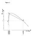
- FIGS. 2 and 3show the operating principle of a gas generator of the invention in graphic form.
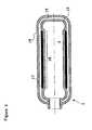
- FIG. 4is a schematic representation of a gas generator of the invention with solid insulation and a valve.
- FIG. 5shows a gas generator of the invention with vacuum insulation and a valve.
- FIG. 6shows a gas generator of the invention with a heating coil.
- FIGS. 7 a and 7 bshow a gas generator of the invention with heating rods.
- FIG. 8shows a gas generator of the invention with solid insulation and a diaphragm.
- the passenger restraint system for vehicles shown in FIG. 1consists of an impact cushion 24 coupled with a gas generator 1 and an activating and monitoring unit 25 .
- the activating and monitoring unit 25records by a sensor unit 26 when well-defined deceleration values are exceeded, such as the deceleration values that occur in serious accidents.
- the activating and monitoring unit 25operates a seal 2 designed as a solenoid valve to initiate depressurization of the water heated in the pressure chamber 3 .
- the pressure releasecauses sudden, technically instantaneous, vaporization of the water.
- the steam produced by this rapid vaporizationdeploys and inflates the impact cushion 24 .
- waterhas a specific volume of 1.658 liters per kg (see FIG. 3 ).
- the pressure chamber 3When the pressure chamber 3 is depressurized, i.e., when the restraint system is activated, the pressure drops to the ambient pressure of about 1 bar, and the quantity of liquid water m 0 in the pressure chamber 3 becomes distributed between a vapor state B and a liquid state C.
- the vaporAt a pressure of 1 bar, the vapor has an enthalpy of 2,675 kJ/kg, a temperature of 100° C., and a specific volume of 1.694 cubic meters per kg (FIG. 3 ). Relative to its value in state A, the specific volume has increased by a factor of 1,000.
- a portion of the water remaining in the chamberis in the liquid state C with the values 1 bar, 100° C., and an enthalpy of 417.5 kJ/kg.
- the specific volumeis 1.03 liters per kg (FIG. 3 ).
- the mass proportions into which the water is distributed upon release of the pressureare obtained from the enthalpy balance:
- the heat content of the water in state Ais equal to the sum of the heat contents of the masses of water in states B and C. Energy losses during the transition from state A to states B and C are negligibly small due to the virtually instantaneous change.
- this enthalpy balanceyields the following ratio for the mass in state B to the mass in state A:
- FIG. 4shows an example of a suitable gas generator 1 , whose pressure chamber 3 is filled with water as the vaporizable substance.
- the pressure chamber 3is surrounded by insulation 4 and can be heated by a heating device, which is shown in FIG. 6 .
- the quantity of water contained in the pressure chambercontains the heat content required to deploy and inflate the impact cushion 24 , which is shown in FIG. 1 .
- the operational state of the pressure chamber 3is attained by heating the water with the heating device until the given quantity of water has the heat content required for the degree of vaporization needed to deploy the impact cushion and inflate it with steam virtually instantaneously, i.e., in about 10-30 milliseconds.
- the insulation 4reduces heat loss from the water to the environment and thus the thermal energy that must be supplied to maintain the operational state of the system.
- the seal 2 in the embodiment shown in FIG. 4is designed as a valve.
- a cylindrical pin 7 with an outlet opening 8is movably mounted in a guide block 6 with a cylindrical passage.
- a transverse channel 9which can be aligned with an outlet 11 of the pressure chamber 3 by moving the pin, opens approximately into the middle section of the outlet opening 8 .
- Several O-rings 12produce a gastight seal between the cylindrical pin 7 and the guide block 6 .
- the pin 7can be moved in the direction of the double arrow, for example, by an electromagnet (not shown in FIG. 4 ), which is controlled by the activating and monitoring unit 25 .
- the end face of the seal 2has a connector 5 , to which an impact cushion 24 (not shown) is connected either directly or by a supply line, which in this case supplies steam to a spatially remote impact cushion.
- the gas generator 1 in FIG. 5has the same seal as the gas generator in FIG. 4 , so the explanation provided in connection with FIG. 4 applies here as well.
- the pressure chamber 3has a double-walled construction. Between the walls 13 , 14 , there is an evacuated annular space 15 that surrounds the pressure chamber 3 as an insulator.
- FIG. 6also shows a gas generator 1 with an insulating annular space 15 .
- the wall 13has a narrowed region 16 surrounded by a heating coil 17 .
- the heating coil 17is supplied with electric power from the electrical system of a vehicle by electrical lines (not shown in FIG. 6 ).
- the seal 2 for releasing the pressure from the pressure chamber 3 and the power supply lines for the heating coil 17are not shown in FIG. 6 .
- FIGS. 7 a and 7 bshow a gas generator 1 with heating rods 18 that extend in the axial direction of the pressure chamber 3 .
- the heating rods 18are installed in the insulating annular space 15 in axial hollows 19 in the wall 13 .
- the seal 2 and the electrical lines that supply power to the heating rods 18are not shown in FIGS. 7 a and 7 b.
- FIG. 8shows a gas generator with a pressure chamber 3 with the same construction as in FIG. 4 , except that it has a different type of seal 2 .
- the seal 2consists of a diaphragm 21 , which is securely attached along its outer edge with an insert 22 , which in turn is screwed into the outlet 11 of the pressure chamber 3 .
- a punch 23can be moved in the axial direction of the pressure chamber 3 by means not shown in FIG. 8 , such as an electromagnet or a pyrotechnic charge. When the passenger restraint system is activated, the punch 23 punches through and destroys the diaphragm 21 . This results in depressurization of the water in the pressure chamber 3 and deployment and inflation of the impact cushion 24 , which is not shown in the drawing.
Landscapes
- Physics & Mathematics (AREA)
- Fluid Mechanics (AREA)
- Engineering & Computer Science (AREA)
- Mechanical Engineering (AREA)
- Air Bags (AREA)
- Feeding, Discharge, Calcimining, Fusing, And Gas-Generation Devices (AREA)
Abstract
Description
- 0.53:1{(1,606.1−417.5):(2,675.4−417.5)}
Claims (17)
Applications Claiming Priority (5)
| Application Number | Priority Date | Filing Date | Title |
|---|---|---|---|
| DE10040000 | 2000-08-11 | ||
| DE10040000.0 | 2000-08-11 | ||
| DE10056228ADE10056228A1 (en) | 2000-08-11 | 2000-11-13 | Gas generator and restraint system for a vehicle |
| DE10056228.0 | 2000-11-13 | ||
| PCT/EP2001/008346WO2002014118A1 (en) | 2000-08-11 | 2001-07-19 | Gas generator and restraint system for a vehicle |
Publications (2)
| Publication Number | Publication Date |
|---|---|
| US20030178830A1 US20030178830A1 (en) | 2003-09-25 |
| US6932383B2true US6932383B2 (en) | 2005-08-23 |
Family
ID=26006712
Family Applications (1)
| Application Number | Title | Priority Date | Filing Date |
|---|---|---|---|
| US10/344,497Expired - Fee RelatedUS6932383B2 (en) | 2000-08-11 | 2001-07-19 | Gas generator and restraint system for a vehicle |
Country Status (8)
| Country | Link |
|---|---|
| US (1) | US6932383B2 (en) |
| EP (1) | EP1307363B1 (en) |
| JP (1) | JP4243753B2 (en) |
| AT (1) | ATE278580T1 (en) |
| AU (1) | AU2001289694A1 (en) |
| CA (1) | CA2418969C (en) |
| ES (1) | ES2225603T3 (en) |
| WO (1) | WO2002014118A1 (en) |
Cited By (11)
| Publication number | Priority date | Publication date | Assignee | Title |
|---|---|---|---|---|
| US20100246119A1 (en)* | 2009-03-27 | 2010-09-30 | Qualcomm Incorporated | Portable docking station for a portable computing device |
| US20100251361A1 (en)* | 2009-03-27 | 2010-09-30 | Qualcomm Incorporated | System and method of managing security between a portable computing device and a portable computing device docking station |
| US20100250975A1 (en)* | 2009-03-27 | 2010-09-30 | Qualcomm Incorporated | System and method of providing scalable computing between a portable computing device and a portable computing device docking station |
| US20100250789A1 (en)* | 2009-03-27 | 2010-09-30 | Qualcomm Incorporated | System and method of managing memory at a portable computing device and a portable computing device docking station |
| US20100244765A1 (en)* | 2009-03-27 | 2010-09-30 | Qualcomm Incorporated | System and method of managing power at a portable computing device and a portable computing device docking station |
| US20100251243A1 (en)* | 2009-03-27 | 2010-09-30 | Qualcomm Incorporated | System and method of managing the execution of applications at a portable computing device and a portable computing device docking station |
| US20100250816A1 (en)* | 2009-03-27 | 2010-09-30 | Qualcomm Incorporated | System and method of managing displays at a portable computing device and a portable computing device docking station |
| US7857345B1 (en) | 2007-07-06 | 2010-12-28 | Tk Holdings, Inc. | Valve assembly for gas generating system |
| US7914040B1 (en) | 2007-04-27 | 2011-03-29 | Tk Holdings, Inc. | Cold gas generating system |
| US8113542B1 (en) | 2008-01-22 | 2012-02-14 | Tk Holdings, Inc. | Pressurized gas release mechanism |
| US8123878B1 (en) | 2007-05-31 | 2012-02-28 | Tk Holdings, Inc. | Gas generating system |
Families Citing this family (5)
| Publication number | Priority date | Publication date | Assignee | Title |
|---|---|---|---|---|
| US7393009B2 (en)* | 2004-09-30 | 2008-07-01 | Automotive Systems Laboratory, Inc. | Dual-flow inflator |
| JP4953750B2 (en)* | 2006-10-11 | 2012-06-13 | 日本プラスト株式会社 | Airbag module |
| JP5291876B2 (en)* | 2006-11-06 | 2013-09-18 | 国防部軍備局中山科学研究院 | Adjustable collision trigger device and method |
| US20160333826A1 (en)* | 2015-05-12 | 2016-11-17 | Busek Co., Inc. | Post-Launch CO2 Gas Production System |
| DE102020118712A1 (en)* | 2020-07-15 | 2022-01-20 | Zf Automotive Germany Gmbh | Safety system for a motor vehicle, method for controlling a safety system and control device |
Citations (13)
| Publication number | Priority date | Publication date | Assignee | Title |
|---|---|---|---|---|
| GB1333959A (en) | 1970-04-30 | 1973-10-17 | Nissan Motor | Safety device for motor vehicle |
| US3994506A (en)* | 1970-06-20 | 1976-11-30 | Klippan Gmbh | Inflatable air bag for motor vehicles for attenuating the impact effect of the passenger in case of accident |
| US4026580A (en) | 1970-11-02 | 1977-05-31 | Daimler-Benz Aktiengesellschaft | Temperature maintaining device for safety gas cushion |
| US4126325A (en)* | 1970-06-20 | 1978-11-21 | Klippan Gmbh Hamburg | Inflatable air bag for motor vehicles for attenuating the impact effect of the passenger in case of accident |
| DE4309241A1 (en) | 1993-03-23 | 1994-09-29 | Wagner Gmbh J | Device for removing wallpaper |
| US5433476A (en) | 1994-07-27 | 1995-07-18 | Breed Automotive Technology, Inc. | Temperature compensated stored gas inflator |
| JPH07257311A (en) | 1994-03-25 | 1995-10-09 | Japan Steel Works Ltd:The | Airbag device |
| DE4419313A1 (en) | 1994-06-01 | 1995-12-07 | Hs Tech & Design | Gas generator |
| US5527066A (en) | 1991-12-10 | 1996-06-18 | Aga Aktiebolag | Airbag filling arrangement |
| DE19612581A1 (en) | 1996-03-29 | 1997-10-02 | Temic Bayern Chem Airbag Gmbh | Gas and vapour generator especially for airbag |
| US6076468A (en)* | 1998-03-26 | 2000-06-20 | Atlantic Research Corporation | Solid propellant/water type hybrid gas generator |
| US6149191A (en)* | 1998-11-16 | 2000-11-21 | Autoliv Asp, Inc. | Carborane-containing airbag inflator |
| US6155600A (en)* | 1996-01-25 | 2000-12-05 | Reynolds; George L. | Safety air bag inflation device |
Family Cites Families (1)
| Publication number | Priority date | Publication date | Assignee | Title |
|---|---|---|---|---|
| DE196125C (en) |
- 2001
- 2001-07-19USUS10/344,497patent/US6932383B2/ennot_activeExpired - Fee Related
- 2001-07-19JPJP2002519232Apatent/JP4243753B2/ennot_activeExpired - Fee Related
- 2001-07-19ATAT01969434Tpatent/ATE278580T1/ennot_activeIP Right Cessation
- 2001-07-19ESES01969434Tpatent/ES2225603T3/ennot_activeExpired - Lifetime
- 2001-07-19EPEP01969434Apatent/EP1307363B1/ennot_activeExpired - Lifetime
- 2001-07-19CACA002418969Apatent/CA2418969C/ennot_activeExpired - Fee Related
- 2001-07-19AUAU2001289694Apatent/AU2001289694A1/ennot_activeAbandoned
- 2001-07-19WOPCT/EP2001/008346patent/WO2002014118A1/enactiveIP Right Grant
Patent Citations (14)
| Publication number | Priority date | Publication date | Assignee | Title |
|---|---|---|---|---|
| GB1333959A (en) | 1970-04-30 | 1973-10-17 | Nissan Motor | Safety device for motor vehicle |
| US3994506A (en)* | 1970-06-20 | 1976-11-30 | Klippan Gmbh | Inflatable air bag for motor vehicles for attenuating the impact effect of the passenger in case of accident |
| US4126325A (en)* | 1970-06-20 | 1978-11-21 | Klippan Gmbh Hamburg | Inflatable air bag for motor vehicles for attenuating the impact effect of the passenger in case of accident |
| US4026580A (en) | 1970-11-02 | 1977-05-31 | Daimler-Benz Aktiengesellschaft | Temperature maintaining device for safety gas cushion |
| US5527066A (en) | 1991-12-10 | 1996-06-18 | Aga Aktiebolag | Airbag filling arrangement |
| US5447597A (en)* | 1993-03-23 | 1995-09-05 | J. Wagner Gmbh | Apparatus for loosening wallpaper |
| DE4309241A1 (en) | 1993-03-23 | 1994-09-29 | Wagner Gmbh J | Device for removing wallpaper |
| JPH07257311A (en) | 1994-03-25 | 1995-10-09 | Japan Steel Works Ltd:The | Airbag device |
| DE4419313A1 (en) | 1994-06-01 | 1995-12-07 | Hs Tech & Design | Gas generator |
| US5433476A (en) | 1994-07-27 | 1995-07-18 | Breed Automotive Technology, Inc. | Temperature compensated stored gas inflator |
| US6155600A (en)* | 1996-01-25 | 2000-12-05 | Reynolds; George L. | Safety air bag inflation device |
| DE19612581A1 (en) | 1996-03-29 | 1997-10-02 | Temic Bayern Chem Airbag Gmbh | Gas and vapour generator especially for airbag |
| US6076468A (en)* | 1998-03-26 | 2000-06-20 | Atlantic Research Corporation | Solid propellant/water type hybrid gas generator |
| US6149191A (en)* | 1998-11-16 | 2000-11-21 | Autoliv Asp, Inc. | Carborane-containing airbag inflator |
Cited By (17)
| Publication number | Priority date | Publication date | Assignee | Title |
|---|---|---|---|---|
| US7914040B1 (en) | 2007-04-27 | 2011-03-29 | Tk Holdings, Inc. | Cold gas generating system |
| US8123878B1 (en) | 2007-05-31 | 2012-02-28 | Tk Holdings, Inc. | Gas generating system |
| US7857345B1 (en) | 2007-07-06 | 2010-12-28 | Tk Holdings, Inc. | Valve assembly for gas generating system |
| US8113542B1 (en) | 2008-01-22 | 2012-02-14 | Tk Holdings, Inc. | Pressurized gas release mechanism |
| US20100244765A1 (en)* | 2009-03-27 | 2010-09-30 | Qualcomm Incorporated | System and method of managing power at a portable computing device and a portable computing device docking station |
| US20100251243A1 (en)* | 2009-03-27 | 2010-09-30 | Qualcomm Incorporated | System and method of managing the execution of applications at a portable computing device and a portable computing device docking station |
| US20100250816A1 (en)* | 2009-03-27 | 2010-09-30 | Qualcomm Incorporated | System and method of managing displays at a portable computing device and a portable computing device docking station |
| US20100246119A1 (en)* | 2009-03-27 | 2010-09-30 | Qualcomm Incorporated | Portable docking station for a portable computing device |
| US20100250789A1 (en)* | 2009-03-27 | 2010-09-30 | Qualcomm Incorporated | System and method of managing memory at a portable computing device and a portable computing device docking station |
| US20100250975A1 (en)* | 2009-03-27 | 2010-09-30 | Qualcomm Incorporated | System and method of providing scalable computing between a portable computing device and a portable computing device docking station |
| US20100251361A1 (en)* | 2009-03-27 | 2010-09-30 | Qualcomm Incorporated | System and method of managing security between a portable computing device and a portable computing device docking station |
| US8630088B2 (en) | 2009-03-27 | 2014-01-14 | Qualcomm Incorporated | Portable docking station for a portable computing device |
| US8653785B2 (en) | 2009-03-27 | 2014-02-18 | Qualcomm Incorporated | System and method of managing power at a portable computing device and a portable computing device docking station |
| US8707061B2 (en) | 2009-03-27 | 2014-04-22 | Qualcomm Incorporated | System and method of providing scalable computing between a portable computing device and a portable computing device docking station |
| US9128669B2 (en) | 2009-03-27 | 2015-09-08 | Qualcomm Incorporated | System and method of managing security between a portable computing device and a portable computing device docking station |
| US9152196B2 (en) | 2009-03-27 | 2015-10-06 | Qualcomm Incorporated | System and method of managing power at a portable computing device and a portable computing device docking station |
| US9201593B2 (en) | 2009-03-27 | 2015-12-01 | Qualcomm Incorporated | System and method of managing displays at a portable computing device and a portable computing device docking station |
Also Published As
| Publication number | Publication date |
|---|---|
| CA2418969A1 (en) | 2002-02-21 |
| EP1307363B1 (en) | 2004-10-06 |
| JP4243753B2 (en) | 2009-03-25 |
| AU2001289694A1 (en) | 2002-02-25 |
| JP2004505850A (en) | 2004-02-26 |
| ES2225603T3 (en) | 2005-03-16 |
| ATE278580T1 (en) | 2004-10-15 |
| CA2418969C (en) | 2008-06-10 |
| WO2002014118A1 (en) | 2002-02-21 |
| EP1307363A1 (en) | 2003-05-07 |
| US20030178830A1 (en) | 2003-09-25 |
Similar Documents
| Publication | Publication Date | Title |
|---|---|---|
| US6932383B2 (en) | Gas generator and restraint system for a vehicle | |
| CA1047564A (en) | Inflation apparatus for safety device | |
| JP3048098U (en) | Inflator | |
| US3806153A (en) | Safety bag inflation for vehicles | |
| US3901530A (en) | Multiple mini hybrid with direct bag connection | |
| US10359150B2 (en) | System for storing a pressurized gas and method for emptying a storage container for a pressurized gas | |
| JP3040975U (en) | Projectile gas release hybrid inflator | |
| US5301979A (en) | Piston driven cold gas air bag inflator | |
| EP0688703B1 (en) | Apparatus for inflating an inflatable vehicle occupant restraint | |
| US5496062A (en) | Liquid-fueled device to combine the functions of a low pressure switch (LPS), squib, and gas generator | |
| SE9703574D0 (en) | Airbag inflating device | |
| US4050483A (en) | Inflation surge delay | |
| US5738372A (en) | Device for pressure relief during bonfire and tell-tale of compressed gas | |
| US20020105219A1 (en) | Aircraft seat structure | |
| CN103068639B (en) | Comprise the gas generator of two kinds of pyrotechnical charge | |
| CN102143865A (en) | Inflator for an airbag | |
| US3618974A (en) | Vehicle safety apparatus | |
| JP4115087B2 (en) | Two-stage gas generator | |
| US5421609A (en) | Rupture device | |
| WO2002018182A1 (en) | Inflator | |
| JPH06503532A (en) | Restraint system that expands with electric heat | |
| US5601310A (en) | Hybrid inflator and method of use | |
| US20050140128A1 (en) | Cold gas generator | |
| US6962365B2 (en) | Inflation gas generation devices and methods utilizing joule-thomson heating | |
| WO2011024203A2 (en) | Airbag inflator system |
Legal Events
| Date | Code | Title | Description |
|---|---|---|---|
| CC | Certificate of correction | ||
| AS | Assignment | Owner name:FLAMM AG, GERMANY Free format text:ASSIGNMENT OF ASSIGNORS INTEREST;ASSIGNOR:FLAMM, FRIEDER;REEL/FRAME:018757/0581 Effective date:20061030 | |
| CC | Certificate of correction | ||
| FEPP | Fee payment procedure | Free format text:PAYOR NUMBER ASSIGNED (ORIGINAL EVENT CODE: ASPN); ENTITY STATUS OF PATENT OWNER: LARGE ENTITY | |
| FEPP | Fee payment procedure | Free format text:PAT HOLDER NO LONGER CLAIMS SMALL ENTITY STATUS, ENTITY STATUS SET TO UNDISCOUNTED (ORIGINAL EVENT CODE: STOL); ENTITY STATUS OF PATENT OWNER: LARGE ENTITY | |
| REFU | Refund | Free format text:REFUND - SURCHARGE, PETITION TO ACCEPT PYMT AFTER EXP, UNINTENTIONAL (ORIGINAL EVENT CODE: R2551); ENTITY STATUS OF PATENT OWNER: LARGE ENTITY | |
| FPAY | Fee payment | Year of fee payment:4 | |
| SULP | Surcharge for late payment | ||
| AS | Assignment | Owner name:FLAMM GMBH, GERMANY Free format text:CHANGE OF NAME;ASSIGNOR:FLAMM AG;REEL/FRAME:029742/0230 Effective date:20120622 | |
| FPAY | Fee payment | Year of fee payment:8 | |
| REMI | Maintenance fee reminder mailed | ||
| LAPS | Lapse for failure to pay maintenance fees | Free format text:PATENT EXPIRED FOR FAILURE TO PAY MAINTENANCE FEES (ORIGINAL EVENT CODE: EXP.) | |
| STCH | Information on status: patent discontinuation | Free format text:PATENT EXPIRED DUE TO NONPAYMENT OF MAINTENANCE FEES UNDER 37 CFR 1.362 | |
| FP | Lapsed due to failure to pay maintenance fee | Effective date:20170823 |