US6931901B2 - Method and apparatus for forming a threaded hole in a hydroformed part - Google Patents
Method and apparatus for forming a threaded hole in a hydroformed partDownload PDFInfo
- Publication number
- US6931901B2 US6931901B2US10/690,100US69010003AUS6931901B2US 6931901 B2US6931901 B2US 6931901B2US 69010003 AUS69010003 AUS 69010003AUS 6931901 B2US6931901 B2US 6931901B2
- Authority
- US
- United States
- Prior art keywords
- tool
- thread
- hole
- piercing
- extruding
- Prior art date
- Legal status (The legal status is an assumption and is not a legal conclusion. Google has not performed a legal analysis and makes no representation as to the accuracy of the status listed.)
- Expired - Fee Related, expires
Links
- 238000000034methodMethods0.000titleclaimsabstractdescription16
- 239000000463materialSubstances0.000claimsabstractdescription15
- 238000006073displacement reactionMethods0.000claimsabstract4
- 230000036961partial effectEffects0.000claimsdescription24
- 239000012530fluidSubstances0.000claimsdescription8
- 230000002028prematureEffects0.000claimsdescription3
- 230000001154acute effectEffects0.000claimsdescription2
- 238000004513sizingMethods0.000abstractdescription12
- 230000015572biosynthetic processEffects0.000description12
- 238000000605extractionMethods0.000description4
- 238000001125extrusionMethods0.000description4
- 238000005520cutting processMethods0.000description3
- 230000002441reversible effectEffects0.000description3
- 238000010079rubber tappingMethods0.000description3
- 238000000227grindingMethods0.000description2
- 239000002184metalSubstances0.000description2
- 229910001315Tool steelInorganic materials0.000description1
- 230000002411adverseEffects0.000description1
- 230000004323axial lengthEffects0.000description1
- 230000003028elevating effectEffects0.000description1
- 238000011010flushing procedureMethods0.000description1
- 239000006193liquid solutionSubstances0.000description1
- 230000001050lubricating effectEffects0.000description1
- 238000004519manufacturing processMethods0.000description1
- 230000002829reductive effectEffects0.000description1
- 230000000717retained effectEffects0.000description1
- XLYOFNOQVPJJNP-UHFFFAOYSA-NwaterSubstancesOXLYOFNOQVPJJNP-UHFFFAOYSA-N0.000description1
Images


Classifications
- B—PERFORMING OPERATIONS; TRANSPORTING
- B21—MECHANICAL METAL-WORKING WITHOUT ESSENTIALLY REMOVING MATERIAL; PUNCHING METAL
- B21D—WORKING OR PROCESSING OF SHEET METAL OR METAL TUBES, RODS OR PROFILES WITHOUT ESSENTIALLY REMOVING MATERIAL; PUNCHING METAL
- B21D28/00—Shaping by press-cutting; Perforating
- B21D28/24—Perforating, i.e. punching holes
- B21D28/28—Perforating, i.e. punching holes in tubes or other hollow bodies
- Y—GENERAL TAGGING OF NEW TECHNOLOGICAL DEVELOPMENTS; GENERAL TAGGING OF CROSS-SECTIONAL TECHNOLOGIES SPANNING OVER SEVERAL SECTIONS OF THE IPC; TECHNICAL SUBJECTS COVERED BY FORMER USPC CROSS-REFERENCE ART COLLECTIONS [XRACs] AND DIGESTS
- Y10—TECHNICAL SUBJECTS COVERED BY FORMER USPC
- Y10T—TECHNICAL SUBJECTS COVERED BY FORMER US CLASSIFICATION
- Y10T29/00—Metal working
- Y10T29/49—Method of mechanical manufacture
- Y10T29/49805—Shaping by direct application of fluent pressure
- Y—GENERAL TAGGING OF NEW TECHNOLOGICAL DEVELOPMENTS; GENERAL TAGGING OF CROSS-SECTIONAL TECHNOLOGIES SPANNING OVER SEVERAL SECTIONS OF THE IPC; TECHNICAL SUBJECTS COVERED BY FORMER USPC CROSS-REFERENCE ART COLLECTIONS [XRACs] AND DIGESTS
- Y10—TECHNICAL SUBJECTS COVERED BY FORMER USPC
- Y10T—TECHNICAL SUBJECTS COVERED BY FORMER US CLASSIFICATION
- Y10T83/00—Cutting
- Y10T83/04—Processes
- Y10T83/0596—Cutting wall of hollow work
Definitions
- This inventionrelates to forming a threaded hole in a hydroformed part and more particularly to doing so while the part remains in the hydroforming dies.
- a holeis formed and threaded in a hydroformed part in an in-die procedure and in a manner that does not produce either a slug or chips.
- the apparatuscomprises a compact hole and thread forming unit that can readily be incorporated in otherwise conventional hydroforming apparatus and performs all its operations while the hydroformed part remains in the dies.
- the hole and thread forming unitcomprises a combined hole piercing, extruding, hole sizing and thread forming tool and an actuator device that advances and retracts the tool and also selectively rotates the tool in both a forward and reverse direction for the threading and tool retraction operations.
- the toolis fed at a feed rate determined by the pitch of the thread to be formed in a threading operation and is retracted at the same rate but in the opposite rotational direction to release the tool from the formed thread.
- the manner of tapping in accordance with the present inventionis hereinafter referred to as “hydrotapping” in light of the accepted term “hydropiercing”.
- the hole and thread forming unitis mounted on one of the dies with its tool closely received in a through bore in this die opposite where a threaded hole is required in the hydroformed part.
- the toolis a one-piece tool having a hole-piercing end portion at one end, an extruding portion adjoining the end portion, a hole-sizing portion adjoining the extruding portion, a relief portion adjoining the hole-sizing portion, a thread-forming portion adjoining the relief portion, and a tool-fastening portion at the other end of the tool.
- the hole piercing end portionis adapted on advancement of the tool by the actuator device to pierce and form a hole in the part without producing a slug and while hydroforming pressure remains in the part to support this operation.
- the extruding portion of the toolis on the other hand adapted on continued tool advancement to enter the pierced hole and extrude an annular region of the part to a predetermined depth inward of the part while expanding the hole to an undersize diameter along its depth and with this operation being assisted with a flushing and lubricating action by the hydroforming fluid that is forced by the pressure remaining in the part after the piercing operation.
- the hole-sizing portion of the toolhas a partial thread by which it is adapted at its crest and on continued tool advancement to radially expand the extruded annular portion to enlarge the hole to a predetermined diameter.
- the extruding formation and the hole sizing of the annular extruded portionforms a hole having a wall thickness essentially the same as the part but a depth dimension that is considerably larger than the wall thickness and that can be varied by the amount of extrusion to allow for a sufficient number of threads to securely hold a particular screw or a bolt.
- the thread-forming portion of the toolhas a full thread that with the intervening relief portion is an interrupted continuation of the partial thread and has the same pitch but a relatively sharp edged crest and a larger major diameter.
- the full threadis by selection of the proper thread forming configuration adapted to form the required thread in the wall of the hole on continued tool advancement and now turning of the tool in the proper direction. Wherein the tool is fed at a feed rate equal to the pitch of the tool threads (both the full and the partial thread) and that of the required thread.
- the toolis simply retracted at the same feed rate while being rotated in the opposite direction by the actuator device to free the tool from the thus finished hydroformed part with the required threaded hole and allow the finished part to be removed from the dies.
- the partial thread of the toolby virtue of its smaller major diameter not wiping out the formed thread in the part as the tool is threadably backed out at the above feed rate.
- the toolis not rotated during the piercing, extruding and hole-sizing operations to minimize the requirements of the tool actuator.
- the toolmay also be rotated during these operations with the result that better hole definition is made possible by reducing the possibility of collapse of the surrounding wall of the part.
- the threaded holecan be formed concurrently with the formation of one or more holes that are also required in the hydroformed part using a hydropiercing operation.
- the formation of the threaded hole using both a hydropiercing operation and a hydrotapping operation in forming a required threaded hole in the part in accordance with the present invention and concurrently with a separate hole forming hydropiercing operationstill does not add substantially to the total cycle time required to process a part that requires both a threaded hole and a plain hole. And with the added advantage that neither a slug or chips are produced in the processing of such a part.
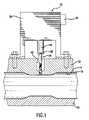
- FIG. 1is a partial side view in section of hydroforming apparatus incorporating an in-die, hole forming, hydrotapping unit according the present invention comprising a tool and actuator device as employed to completely form a required threaded hole in a hydroformed part,
- FIG. 2is an enlarged view of the tool in FIG. 1 ,
- FIG. 3is an enlarged view taken along the lines 3 — 3 in FIG. 2 when looking in the direction of the arrows,
- FIGS. 4–8are partial views taken from FIG. 1 showing the sequential steps in the formation of a required threaded hole in the hydroformed part using the tool in FIGS. 1–3 ,
- FIG. 9is a view similar to FIG. 2 but of another embodiment of the tool.
- FIG. 10is an enlarged view taken along the lines 10 — 10 in FIG. 9 when looking in the direction of the arrows,
- FIG. 11shows a modified form of the piercing end of the tool in FIGS. 9 and 10 .
- FIGS. 12–16are views similar to FIGS. 4–8 showing the sequential steps in the formation of a required threaded hole in the hydroformed part using the tool in FIGS. 9 and 10 .
- FIG. 1there is shown a portion of a conventional hydroforming apparatus comprising a lower die 10 and an upper die 12 that co-operatively form a cavity 14 having a surface conforming to the required shape of the finished part.
- a piece of tubular metal stockis captured between the dies in the die cavity and a hydroforming fluid typically in the form of a water based liquid solution is then delivered through one end of the part to the interior of the part while exit from the other end is blocked.
- the hydroforming fluidthus delivered being maintained at a pressure sufficient to forcibly expand the wall of the captured part outward against and conform to the cavity surface to thereby form a hydroformed part 15 having the required shape.
- a hole and thread forming unit 16comprising a singular tool 18 and an actuator device 20 that operates the tool 18 .
- the tool 18also being referred to herein as a hydrotapping tool in view of its functioning.
- the hydrotapping tool 18is a flute-less, one-piece tool that is made of suitable tool steel and comprises a plurality of differently configured portions. With these portions comprising a hole-piercing end portion 22 at one end of the tool, an adjoining extruding portion 24 , an adjoining hole-sizing or expanding portion 26 , an adjoining relief portion 28 , an adjoining thread forming portion 30 , and a square or other suitably shaped shank portion 32 at the other end of the tool for fastening the tool to the actuator device 20 .
- the actuator device 20which is also referred to as a drive unit is of any suitable type adapted to drive the tool 18 in the manner prescribed herein.
- the actuator device 20may be an electric motor powered drive unit or an electo-hydraulic powered drive unit or other type of suitable drive unit.
- the actuator devicehas a programmable control system 34 and a projecting drive shaft 36 having a drive socket in the end thereof in which the shank end portion 32 of the tool 18 is inserted and held with a setscrew 38 . And wherein the actuator device is operational to advance, retract and rotate the drive shaft 36 and thereby the tool 18 .
- certain prescribed feed ratescan be programmed into the control system 34 to advance and retract the tool 18 at variable linear feed rates and also rotate and feed the tool 18 at a certain feed rate matching the pitch of the particular thread for which the tool is adapted to tap as described in more detail later.
- the threaded hole required in the hydroformed partmay for example be located on the upper side of the part as viewed in FIG. 1 and the unit 16 is accordingly rigidly mounted as shown on the top of the upper die 12 .
- the end of the drive shaft 36 and the smaller diameter tool 18are closely receivable in a stepped bore 40 that extends through the upper die 12 and through the die cavity surface therein and is in alignment with where the threaded hole is required in the hydroformed part.
- the piercing end portion 22 of the tool 18has a pointed end 42 with an adjoining radially outwardly diverging or outwardly angled multi-faceted surface 44 and a cylindrical surface 46 that adjoins the faceted surface 44 .
- the toolis initially located by the actuator device 20 at the start of the hydroforming process in a position where the tool point 42 is flush with the surrounding cavity surface as shown in FIGS. 1 and 4 .
- the tool point 42may be positioned in a slightly retracted position with respect to the surrounding die cavity surface as it was found that this would also not adversely affect the subsequent tool operation described below.
- the tool 18is advanced by the actuator device 20 immediately following the hydroforming of the part while the hydroforming pressure is maintained therein with such initial tool advancement causing the pointed end 42 and then the trailing faceted surface 44 and then the trailing cylindrical surface 46 to sequentially and progressively pierce a hole in the wall of the part without producing a slug.
- the hydroforming pressuresupports the wall of the part against collapsing and distorting during the piercing operation at least until the pressure drops significantly at the point where the wall is actually pierced through.
- the wall of the partis sufficiently strong because of its thickness and/or type of material so as to prevent premature piercing of the wall by the hydroforming pressure forcing the wall outward against the pointed end 42 of the tool during the hydroforming of the part.
- the extruding portion 24 of the tool 18has a conical surface 48 diverging radially outward from the cylindrical surface 46 of the tool end portion 22 and by which the tool is adapted on continued advancement by the actuator device 20 to enter the pierced hole and extrude an annular region of the part extending about the pierced hole to a predetermined depth inward of the part.
- an internal tubular neck portion 50 in the partdefining a thus expanded and substantially deepened hole 52 in the part as shown in FIG. 5 prior to the expanding tool portion 26 entering the hole.
- the faceted surface 44 of the piercing end portion 22 of the toolpreferably has four triangular facets of equal size as shown and instead of producing a slug as a result of the piercing by the pointed end 42 , there are resultantly produced four small appendages 54 by the faceted surface as the piercing proceeds and that remain integral with the inner edge of the neck portion 50 . Only two of the appendages 54 which are diagonally opposite each other are shown and it will be understood that the other two are also diagonally opposite each other and spaced 90 degrees from those shown.
- the hole 52 prior to entry of the expanding portion 26 of the toolis made undersize.
- the configurations of the respective hole piercing end portion 22 and extruding portion 24 of the tool 18are determined dimensional wise for a particular application so as to pierce and extrude the wall of the part inwardly to the extent necessary to form the wall of the hole 52 with a depth or axial extent that allows the formation therein of the number of threads required to adequately secure a particular screw or bolt.
- the hole-sizing or expanding portion 26 of the tool 18expands the thus formed hole 52 to the precise diameter best suited for the cold forming of the required thread therein and for that purpose has a thread forming thread 56 (but only a partial one) with a reduced tip radius and having a crest defined by a cylindrical helical surface 58 with rounded edges 60 . See FIG. 2 .
- the expanding portion 26is adapted on continued advancement of the tool by the actuator device 20 to efficiently radially expand the extruded tubular neck portion 50 along its depth or axial length to size the hole 52 to the desired diameter prior to the thread forming operation.
- the hole 52is accurately and precisely sized as required by the subsequent thread forming operation to be performed by the thread-forming portion 30 as this portion of the tool enters the hole 52 on continued tool advancement as shown in FIG. 5 .
- the thread-forming portion 30 of the tool 18has a full thread-forming thread 62 that forms an interrupted continuation of the partial thread 56 with the same pitch and has a relatively sharp crest 64 and a larger major diameter D62 as compared to the partial thread 56 and its major diameter D56. See FIG. 2 .
- the thread-forming portion 30is thereby adapted on continued tool advancement and now also rotation of the tool 18 by the actuator device 20 at a feed rate equal to the pitch of the full thread 62 (and thus also that of the partial thread 56 ) to accurately and precisely form the required thread 66 in the wall of the hole 52 of the extruded and internally sized neck portion 50 as shown in FIG. 6 .
- the full thread 62displaces most of the material (approximately 95%) to the inside of the groove or crevice of this thread in forming the thread 66 in the wall of the hole 52 . With the small remainder of material being displaced outward but not enough to make a significant difference in the outer surface of the hole defining tubular neck portion 50 .
- the relief portion 28 of the tool that is located between the expanding portion 26 and thread-forming portion 30 of the tool 18has a smooth annular surface 68 whose maximum diameter is slightly less than the minor diameter of the partial thread 56 and the full thread 62 . See FIG. 2 .
- the purpose of the relief portion 28being to minimize the friction between the tool and the extruded neck portion 50 formed in the part when the tool while continuing to advance is also initially started to rotate by the actuator device 20 to form the thread 66 .
- the tool 18is then simply retracted from or backed out of the formed thread 66 by the actuator device 20 by the latter rotating the tool 18 in the reverse direction and retracting it at the same feed rate used to form the thread 66 .
- the partial thread 56follows the forming thread 62 and because of its smaller major diameter D56 being at its helical crest surface 58 , the then trailing partial thread 56 does not wipe the crest off the formed thread 66 . See FIG. 7 .
- the tool 18is finally returned to its initial or starting position by the actuator device 20 where the tool is free of the hydroformed part 15 as shown in FIG. 8 .
- the finished partis exhausted of any remaining hydroforming fluid in a conventional manner.
- the dies 10 and 12are then opened by elevating the upper die 12 whereby the finished hydroformed part 15 with the required threaded hole can then be removed to clear the dies for the processing of another part.
- the required threadmay for example be an 8 ⁇ 1.25 mm thread.
- the hole-piercing end portion 22 , extruding portion 24 and the hole-sizing expanding portion 26 of the toolare dimensioned accordingly to form the desired dimensions for the resulting tubular neck portion 50
- the full thread 62is formed with the required thread forming configuration for an 8 ⁇ 1.25 mm thread
- the partial thread 56is provided with the same pitch but with a major diameter D56 at the surface 58 of its helical crest that is substantially smaller than the major diameter D62 of the full thread 62 such that the partial thread can freely return through a 8 ⁇ 1.25 mm thread
- the relief portion 28 of the toolis provided with a maximum diameter slightly less than the minor diameter of the 8 ⁇ 1.25 mm thread.
- control system 34 of the actuator device 20is programmed to feed the tool 18 while turning the tool in the appropriate turning directions during the thread forming and tool extraction operations at a feed rate of 1.25 mm per tool revolution in order to form the required 8 ⁇ 1.25 mm thread and provide for tool extraction on reverse tool rotation without disturbing the formed thread.
- the tool 18can be fed and retracted at certain linear rates that are found to be best suited for the piercing, extruding and expanding (hole-sizing) operations.
- the control system 34 of the actuator device 20to feed the tool 18 at the optimum linear rates best suited to these operations and which for example can be determined by trial and error for each particular application during setup of the hole and thread forming unit 16 .
- the same linear feed ratecan be used for all these operations as well as the rate of tool retraction following these operations in order to minimize the operational requirements of the actuator device 20 .
- FIGS. 9–16wherein parts and features corresponding to those in FIGS. 1–8 are identified by the same reference numbers but in a one hundred (100) numbering series and distinctly different features are identified with reference numbers in a two hundred (200) numbering series.
- the hydrotapping tool 118is now provided with a hole piercing end portion 202 having a blunt end 204 with a flat mainly circular surface 206 that is at right angles to the tool axis and has an adjoining cylindrical surface 208 .
- the diameter of the circular surface 206 forming the blunt end of the tool(which is also the diameter of the adjoining cylindrical surface 208 ) is significantly less than the minor diameter of the required thread as determined by the extent desired of the subsequent extrusion by the tool 118 of the neck portion 150 formed in a part a part 210 substantially different from part 15 . See FIGS. 12–16 .
- the part 210 in this examplehaving a smaller wall thickness as shown and/or being formed of lesser strength material as compared with the part 15 .
- the tool 118is thereby adapted at its piercing end to adequately support the wall of the part 210 against being prematurely pierced outwardly during the hydroforming of the part and which would otherwise occur if a sharp pointed tool end like that on the hydrotapping tool 18 was used for this particular part.
- the blunt end 204is provided with a flat chamfer 212 of limited annular extent that is at an acute angle to the blunt end surface 206 and intersects the otherwise sharp edge of the blunt end 204 and the adjoining cylindrical surface 208 .
- the tool 118is also provided with an extruding portion 216 of different configuration that has a concave-convex annular surface 218 that extends from the cylindrical surface 208 of the piercing end portion 202 of the tool to the relief portion 128 of the tool. See FIGS. 9 and 10 .
- the extruding operationstarts with the concave portion of the surface 218 of the tool extruding portion 216 first entering the pierced hole and finishes with the convex portion of this surface before the expanding portion 126 of the tool enters as the tool continues to be advanced.
- the tool 118is otherwise the same as the tool 18 and operates to form the required threaded hole in the part as shown in FIGS. 12–16 .
- FIG. 12showing the initial positioning of the tool 118
- FIG. 13showing the piercing, expanding and extruding operations having been performed and just prior to the threading operation
- FIG. 14showing the tool threading operation in forming the required thread 166
- FIG. 15showing the tool extraction operation
- FIG. 16showing the tool fully retracted and ready for the commencement of another hole piercing and thread forming sequence of operations with another hydroformed part.
- the extruding portion of the tool 118can instead of the concave-convex surface 218 have a conical surface 148 as shown in FIG. 11 like the conical surface 48 in the embodiment in FIGS. 2 and 3 .
- the desired extrusionis obtained with the tool 118 with either the concave-convex surface 218 or the conical surface 148 and with the slug 214 resulting from the prior piercing operation integrally remaining with the extruded neck portion formed in the part.
- the toolis not rotated during the piercing, extruding and expanding (hole-sizing) operations.
- the actuator device 20is of a suitable type that is also operable to rotate the tool during the piercing, extruding and expanding operations.
- the partial and full thread portions and the relief portioncan be formed by first forming a full thread as required that also spans the intended relief portion and the partial thread portion. Where after the overextended portion of the full thread is then simply removed by grinding operations to form the relief portion and the partial thread while leaving the remaining full thread as the actual thread forming portion of the tool. And wherein the hole-piercing end portion and extruding portion are also formed with grinding operations.
Landscapes
- Engineering & Computer Science (AREA)
- Mechanical Engineering (AREA)
- Forging (AREA)
Abstract
Description
Claims (16)
Priority Applications (1)
| Application Number | Priority Date | Filing Date | Title |
|---|---|---|---|
| US10/690,100US6931901B2 (en) | 2003-10-21 | 2003-10-21 | Method and apparatus for forming a threaded hole in a hydroformed part |
Applications Claiming Priority (1)
| Application Number | Priority Date | Filing Date | Title |
|---|---|---|---|
| US10/690,100US6931901B2 (en) | 2003-10-21 | 2003-10-21 | Method and apparatus for forming a threaded hole in a hydroformed part |
Publications (2)
| Publication Number | Publication Date |
|---|---|
| US20050081589A1 US20050081589A1 (en) | 2005-04-21 |
| US6931901B2true US6931901B2 (en) | 2005-08-23 |
Family
ID=34521550
Family Applications (1)
| Application Number | Title | Priority Date | Filing Date |
|---|---|---|---|
| US10/690,100Expired - Fee RelatedUS6931901B2 (en) | 2003-10-21 | 2003-10-21 | Method and apparatus for forming a threaded hole in a hydroformed part |
Country Status (1)
| Country | Link |
|---|---|
| US (1) | US6931901B2 (en) |
Cited By (15)
| Publication number | Priority date | Publication date | Assignee | Title |
|---|---|---|---|---|
| US20050156004A1 (en)* | 2003-12-22 | 2005-07-21 | Edwards Mark S. | Method and apparatus for fracturing seal rings |
| US20060288559A1 (en)* | 2005-06-28 | 2006-12-28 | Ghiran Mircea M | Method and apparatus for attaching a fastener nut to a hydroformed part |
| US20070101787A1 (en)* | 2005-11-01 | 2007-05-10 | Honda Motor Co., Ltd. | Thread forming method, thread forming device, and thread forming tool |
| US20070240482A1 (en)* | 2006-04-14 | 2007-10-18 | Trusted Tooling, Llc | Tooling die slide driver |
| US20080168817A1 (en)* | 2007-01-11 | 2008-07-17 | Gm Global Technology Operations, Inc. | Tool for Forming Threaded Hole in a Hydroformed Part |
| US20100008737A1 (en)* | 2008-07-13 | 2010-01-14 | Gm Global Technology Operations, Inc. | Tool for and method of forming at tapped hole in a single pass |
| US20100294784A1 (en)* | 2009-05-19 | 2010-11-25 | Johnson Welded Products, Inc. | Extruded port for a pressure vessel and method of manufacture thereof |
| DE102015109217A1 (en) | 2014-06-25 | 2015-12-31 | Ford Global Technologies, Llc | Method for producing a grounding point on an aluminum body part |
| US20160354833A1 (en)* | 2015-06-02 | 2016-12-08 | International Business Machines Corporation | Manifold for a liquid cooling system |
| WO2017038976A1 (en)* | 2015-09-03 | 2017-03-09 | 新日鐵住金株式会社 | Hole-widening machining method, molding tool, molding and machining method |
| US20180126444A1 (en)* | 2014-05-13 | 2018-05-10 | Deprag Schulz Gmbh U. Co. | Device for direct screwing of structural components, in particular for flow hole screwing |
| US10054143B2 (en)* | 2015-01-19 | 2018-08-21 | James A. Allmon | Connector device for use in connecting elements of bracing systems and the like |
| US20220203468A1 (en)* | 2020-12-28 | 2022-06-30 | GM Global Technology Operations LLC | Methods of manufacturing part with hole having cut threads |
| US20220266366A1 (en)* | 2021-02-22 | 2022-08-25 | GM Global Technology Operations LLC | Hybrid threading tap with reamer portion and thread cutting portion |
| US11465221B2 (en) | 2020-12-28 | 2022-10-11 | GM Global Technology Operations LLC | Hybrid threading tool with cutting portion and rolling portion |
Citations (19)
| Publication number | Priority date | Publication date | Assignee | Title |
|---|---|---|---|---|
| US93824A (en) | 1869-08-17 | Improved compound tool por water and gas-pipes | ||
| US188405A (en) | 1877-03-13 | Improvement in combined drill, reamer, and tap | ||
| US623614A (en) | 1899-04-25 | Drill for tapping pipes | ||
| US2278377A (en) | 1940-09-07 | 1942-03-31 | Wrentham Products Company | Tap stud or the like |
| US2300310A (en) | 1940-08-23 | 1942-10-27 | American Optical Corp | Tool |
| US2561036A (en) | 1948-06-07 | 1951-07-17 | Noel S Sodders | Thread-cutting sheet metal nut |
| US3131407A (en) | 1962-03-08 | 1964-05-05 | Glynton M Roberts | Thread swaging tap |
| US3238836A (en) | 1964-03-25 | 1966-03-08 | Harry W Johnson | Drilling reaming work extruding self-tapping screw |
| US3245099A (en) | 1963-12-26 | 1966-04-12 | Zagar Inc | Root diameter reamer tap |
| US3919871A (en)* | 1973-07-13 | 1975-11-18 | Novex Rt | Process and apparatus for producing a neck on a metal container having a closed bottom |
| US4316683A (en) | 1979-08-24 | 1982-02-23 | Roger A. Schott | Semi-circular thread tap |
| US4708542A (en) | 1985-04-19 | 1987-11-24 | Greenfield Industries, Inc. | Threading tap |
| US5725336A (en) | 1993-02-11 | 1998-03-10 | Vilmanyi; Laszlo | Thread tapping cutting tool |
| US5737952A (en)* | 1995-09-06 | 1998-04-14 | Behr Gmbh & Co. | Method and apparatus for producing a header with openings |
| US5902079A (en) | 1996-05-28 | 1999-05-11 | Bitmoore, An Oregon General Partnership | Combination die and tap |
| US6098437A (en)* | 1998-03-20 | 2000-08-08 | The Budd Company | Hydroformed control arm |
| US6442820B1 (en)* | 2000-10-26 | 2002-09-03 | F & P Mfg., Inc. | Method and apparatus for forming a tube having an article inserted therein |
| US6591648B1 (en)* | 2002-06-24 | 2003-07-15 | Greenville Tool & Die Company | Method of stamping and piercing a tube |
| US6681611B2 (en)* | 1996-11-20 | 2004-01-27 | Daimlerchrysler Ag | Process and device for manufacturing holes on the circumference of hollow sections |
- 2003
- 2003-10-21USUS10/690,100patent/US6931901B2/ennot_activeExpired - Fee Related
Patent Citations (19)
| Publication number | Priority date | Publication date | Assignee | Title |
|---|---|---|---|---|
| US93824A (en) | 1869-08-17 | Improved compound tool por water and gas-pipes | ||
| US188405A (en) | 1877-03-13 | Improvement in combined drill, reamer, and tap | ||
| US623614A (en) | 1899-04-25 | Drill for tapping pipes | ||
| US2300310A (en) | 1940-08-23 | 1942-10-27 | American Optical Corp | Tool |
| US2278377A (en) | 1940-09-07 | 1942-03-31 | Wrentham Products Company | Tap stud or the like |
| US2561036A (en) | 1948-06-07 | 1951-07-17 | Noel S Sodders | Thread-cutting sheet metal nut |
| US3131407A (en) | 1962-03-08 | 1964-05-05 | Glynton M Roberts | Thread swaging tap |
| US3245099A (en) | 1963-12-26 | 1966-04-12 | Zagar Inc | Root diameter reamer tap |
| US3238836A (en) | 1964-03-25 | 1966-03-08 | Harry W Johnson | Drilling reaming work extruding self-tapping screw |
| US3919871A (en)* | 1973-07-13 | 1975-11-18 | Novex Rt | Process and apparatus for producing a neck on a metal container having a closed bottom |
| US4316683A (en) | 1979-08-24 | 1982-02-23 | Roger A. Schott | Semi-circular thread tap |
| US4708542A (en) | 1985-04-19 | 1987-11-24 | Greenfield Industries, Inc. | Threading tap |
| US5725336A (en) | 1993-02-11 | 1998-03-10 | Vilmanyi; Laszlo | Thread tapping cutting tool |
| US5737952A (en)* | 1995-09-06 | 1998-04-14 | Behr Gmbh & Co. | Method and apparatus for producing a header with openings |
| US5902079A (en) | 1996-05-28 | 1999-05-11 | Bitmoore, An Oregon General Partnership | Combination die and tap |
| US6681611B2 (en)* | 1996-11-20 | 2004-01-27 | Daimlerchrysler Ag | Process and device for manufacturing holes on the circumference of hollow sections |
| US6098437A (en)* | 1998-03-20 | 2000-08-08 | The Budd Company | Hydroformed control arm |
| US6442820B1 (en)* | 2000-10-26 | 2002-09-03 | F & P Mfg., Inc. | Method and apparatus for forming a tube having an article inserted therein |
| US6591648B1 (en)* | 2002-06-24 | 2003-07-15 | Greenville Tool & Die Company | Method of stamping and piercing a tube |
Cited By (29)
| Publication number | Priority date | Publication date | Assignee | Title |
|---|---|---|---|---|
| US20050156004A1 (en)* | 2003-12-22 | 2005-07-21 | Edwards Mark S. | Method and apparatus for fracturing seal rings |
| US20060288559A1 (en)* | 2005-06-28 | 2006-12-28 | Ghiran Mircea M | Method and apparatus for attaching a fastener nut to a hydroformed part |
| US7685690B2 (en)* | 2005-06-28 | 2010-03-30 | Gm Global Technology Operations, Inc. | Method and apparatus for attaching a fastener nut to a hydroformed part |
| US20070101787A1 (en)* | 2005-11-01 | 2007-05-10 | Honda Motor Co., Ltd. | Thread forming method, thread forming device, and thread forming tool |
| JP2007125623A (en)* | 2005-11-01 | 2007-05-24 | Honda Motor Co Ltd | Thread forming method, screw forming apparatus and screw forming tool |
| US7552610B2 (en)* | 2005-11-01 | 2009-06-30 | Honda Motor Co., Ltd. | Thread forming method, thread forming device, and thread forming tool |
| US7712346B2 (en) | 2006-04-14 | 2010-05-11 | Trusted Tooling, Llc | Tooling die slide driver |
| US20070240482A1 (en)* | 2006-04-14 | 2007-10-18 | Trusted Tooling, Llc | Tooling die slide driver |
| US20080168817A1 (en)* | 2007-01-11 | 2008-07-17 | Gm Global Technology Operations, Inc. | Tool for Forming Threaded Hole in a Hydroformed Part |
| US7441433B2 (en) | 2007-01-11 | 2008-10-28 | Gm Global Technology Operations, Inc. | Tool for forming threaded hole in a hydroformed part |
| US20100008737A1 (en)* | 2008-07-13 | 2010-01-14 | Gm Global Technology Operations, Inc. | Tool for and method of forming at tapped hole in a single pass |
| US8220301B2 (en) | 2008-07-13 | 2012-07-17 | GM Global Technology Operations LLC | Tool for and method of forming at tapped hole in a single pass |
| US20100294784A1 (en)* | 2009-05-19 | 2010-11-25 | Johnson Welded Products, Inc. | Extruded port for a pressure vessel and method of manufacture thereof |
| US20180126444A1 (en)* | 2014-05-13 | 2018-05-10 | Deprag Schulz Gmbh U. Co. | Device for direct screwing of structural components, in particular for flow hole screwing |
| DE102015109217A1 (en) | 2014-06-25 | 2015-12-31 | Ford Global Technologies, Llc | Method for producing a grounding point on an aluminum body part |
| RU2674267C2 (en)* | 2014-06-25 | 2018-12-06 | ФОРД ГЛОУБАЛ ТЕКНОЛОДЖИЗ, ЭлЭлСи | Method of fastening grounding wire to aluminium member (versions) and method of fastening electrical grounding point on aluminium member |
| US9816544B2 (en)* | 2014-06-25 | 2017-11-14 | Ford Global Technologies, Llc | Method of forming a grounding point on an aluminum member |
| US10054143B2 (en)* | 2015-01-19 | 2018-08-21 | James A. Allmon | Connector device for use in connecting elements of bracing systems and the like |
| US20160354833A1 (en)* | 2015-06-02 | 2016-12-08 | International Business Machines Corporation | Manifold for a liquid cooling system |
| US10168110B2 (en)* | 2015-06-02 | 2019-01-01 | International Business Machines Corporation | Manifold for a liquid cooling system |
| US20180200772A1 (en)* | 2015-09-03 | 2018-07-19 | Nippon Steel & Sumitomo Metal Corporation | Hole widening method, forming tool, and formed product |
| WO2017038976A1 (en)* | 2015-09-03 | 2017-03-09 | 新日鐵住金株式会社 | Hole-widening machining method, molding tool, molding and machining method |
| RU2687431C1 (en)* | 2015-09-03 | 2019-05-13 | Ниппон Стил Энд Сумитомо Метал Корпорейшн | Hole expansion method, molding tool and molded article |
| US11192161B2 (en)* | 2015-09-03 | 2021-12-07 | Nippon Steel Corporation | Hole widening method, forming tool, and formed product |
| US20220203468A1 (en)* | 2020-12-28 | 2022-06-30 | GM Global Technology Operations LLC | Methods of manufacturing part with hole having cut threads |
| US11465221B2 (en) | 2020-12-28 | 2022-10-11 | GM Global Technology Operations LLC | Hybrid threading tool with cutting portion and rolling portion |
| US11577331B2 (en)* | 2020-12-28 | 2023-02-14 | Gm Global Technology Operatins Llc | Methods of manufacturing part with hole having cut threads |
| US20220266366A1 (en)* | 2021-02-22 | 2022-08-25 | GM Global Technology Operations LLC | Hybrid threading tap with reamer portion and thread cutting portion |
| US11597023B2 (en)* | 2021-02-22 | 2023-03-07 | Gm Global Technology Operatins Llc | Hybrid threading tap with reamer portion and thread cutting portion |
Also Published As
| Publication number | Publication date |
|---|---|
| US20050081589A1 (en) | 2005-04-21 |
Similar Documents
| Publication | Publication Date | Title |
|---|---|---|
| US6931901B2 (en) | Method and apparatus for forming a threaded hole in a hydroformed part | |
| US7441433B2 (en) | Tool for forming threaded hole in a hydroformed part | |
| DK172827B1 (en) | Tool for threading a hole | |
| US4878793A (en) | Screw threaded fastener | |
| JP2020097056A (en) | Riveting method | |
| US5361478A (en) | Method of inserting a hole forming and selftapping screw | |
| KR870000417B1 (en) | Threaded fastener and method of installing same | |
| CA1325085C (en) | Combined hole making and threading tool | |
| US4271554A (en) | Combination drill and tap tool | |
| US4179976A (en) | Extruding and tapping screw and blank for manufacture of such screw | |
| US7107664B2 (en) | Screw thread cutting apparatus and method | |
| EP1389150B1 (en) | A thread forming tap with a non-circular cross-section and radially extending cutting edges | |
| US6658908B1 (en) | Punch for piercing and sealing hydroformed parts | |
| JP2003278729A (en) | Notched screw part and method of manufacturing the same | |
| US4724694A (en) | Method of manufacturing a thread-forming screw | |
| US7685690B2 (en) | Method and apparatus for attaching a fastener nut to a hydroformed part | |
| US20100008737A1 (en) | Tool for and method of forming at tapped hole in a single pass | |
| US4104446A (en) | Self-tapping or thread-forming screw | |
| DE19505111B4 (en) | Cutting tool and method for producing holes in hollow bodies | |
| US7249480B2 (en) | In-die hydropiercing device for piercing holes in hydroformed parts | |
| US6915672B1 (en) | Hydrotapping power unit | |
| EP0918165B1 (en) | Fastening screw and method of forming same | |
| US20080038077A1 (en) | Self-polishing and tapping rivet assembly | |
| US7003995B2 (en) | Hydrotapping power unit | |
| US2812527A (en) | Method of making winged cap nuts |
Legal Events
| Date | Code | Title | Description |
|---|---|---|---|
| AS | Assignment | Owner name:GENERAL MOTORS CORPORATION, MICHIGAN Free format text:ASSIGNMENT OF ASSIGNORS INTEREST;ASSIGNORS:GHIRAN, MIRCEA M.;MELLAS, SPYROS P.;KAUFMAN, BENJAMIN D.;REEL/FRAME:014358/0323;SIGNING DATES FROM 20031001 TO 20031002 | |
| AS | Assignment | Owner name:GM GLOBAL TECHNOLOGY OPERATIONS, INC., MICHIGAN Free format text:ASSIGNMENT OF ASSIGNORS INTEREST;ASSIGNOR:GENERAL MOTORS CORPORATION;REEL/FRAME:022092/0755 Effective date:20050119 Owner name:GM GLOBAL TECHNOLOGY OPERATIONS, INC.,MICHIGAN Free format text:ASSIGNMENT OF ASSIGNORS INTEREST;ASSIGNOR:GENERAL MOTORS CORPORATION;REEL/FRAME:022092/0755 Effective date:20050119 | |
| FPAY | Fee payment | Year of fee payment:4 | |
| AS | Assignment | Owner name:UNITED STATES DEPARTMENT OF THE TREASURY, DISTRICT Free format text:SECURITY AGREEMENT;ASSIGNOR:GM GLOBAL TECHNOLOGY OPERATIONS, INC.;REEL/FRAME:022201/0547 Effective date:20081231 Owner name:UNITED STATES DEPARTMENT OF THE TREASURY,DISTRICT Free format text:SECURITY AGREEMENT;ASSIGNOR:GM GLOBAL TECHNOLOGY OPERATIONS, INC.;REEL/FRAME:022201/0547 Effective date:20081231 | |
| AS | Assignment | Owner name:CITICORP USA, INC. AS AGENT FOR BANK PRIORITY SECU Free format text:SECURITY AGREEMENT;ASSIGNOR:GM GLOBAL TECHNOLOGY OPERATIONS, INC.;REEL/FRAME:022553/0399 Effective date:20090409 Owner name:CITICORP USA, INC. AS AGENT FOR HEDGE PRIORITY SEC Free format text:SECURITY AGREEMENT;ASSIGNOR:GM GLOBAL TECHNOLOGY OPERATIONS, INC.;REEL/FRAME:022553/0399 Effective date:20090409 | |
| AS | Assignment | Owner name:GM GLOBAL TECHNOLOGY OPERATIONS, INC., MICHIGAN Free format text:RELEASE BY SECURED PARTY;ASSIGNOR:UNITED STATES DEPARTMENT OF THE TREASURY;REEL/FRAME:023124/0470 Effective date:20090709 Owner name:GM GLOBAL TECHNOLOGY OPERATIONS, INC.,MICHIGAN Free format text:RELEASE BY SECURED PARTY;ASSIGNOR:UNITED STATES DEPARTMENT OF THE TREASURY;REEL/FRAME:023124/0470 Effective date:20090709 | |
| AS | Assignment | Owner name:GM GLOBAL TECHNOLOGY OPERATIONS, INC., MICHIGAN Free format text:RELEASE BY SECURED PARTY;ASSIGNORS:CITICORP USA, INC. AS AGENT FOR BANK PRIORITY SECURED PARTIES;CITICORP USA, INC. AS AGENT FOR HEDGE PRIORITY SECURED PARTIES;REEL/FRAME:023127/0273 Effective date:20090814 Owner name:GM GLOBAL TECHNOLOGY OPERATIONS, INC.,MICHIGAN Free format text:RELEASE BY SECURED PARTY;ASSIGNORS:CITICORP USA, INC. AS AGENT FOR BANK PRIORITY SECURED PARTIES;CITICORP USA, INC. AS AGENT FOR HEDGE PRIORITY SECURED PARTIES;REEL/FRAME:023127/0273 Effective date:20090814 | |
| AS | Assignment | Owner name:UNITED STATES DEPARTMENT OF THE TREASURY, DISTRICT Free format text:SECURITY AGREEMENT;ASSIGNOR:GM GLOBAL TECHNOLOGY OPERATIONS, INC.;REEL/FRAME:023156/0001 Effective date:20090710 Owner name:UNITED STATES DEPARTMENT OF THE TREASURY,DISTRICT Free format text:SECURITY AGREEMENT;ASSIGNOR:GM GLOBAL TECHNOLOGY OPERATIONS, INC.;REEL/FRAME:023156/0001 Effective date:20090710 | |
| AS | Assignment | Owner name:UAW RETIREE MEDICAL BENEFITS TRUST, MICHIGAN Free format text:SECURITY AGREEMENT;ASSIGNOR:GM GLOBAL TECHNOLOGY OPERATIONS, INC.;REEL/FRAME:023161/0911 Effective date:20090710 Owner name:UAW RETIREE MEDICAL BENEFITS TRUST,MICHIGAN Free format text:SECURITY AGREEMENT;ASSIGNOR:GM GLOBAL TECHNOLOGY OPERATIONS, INC.;REEL/FRAME:023161/0911 Effective date:20090710 | |
| AS | Assignment | Owner name:GM GLOBAL TECHNOLOGY OPERATIONS, INC., MICHIGAN Free format text:RELEASE BY SECURED PARTY;ASSIGNOR:UAW RETIREE MEDICAL BENEFITS TRUST;REEL/FRAME:025311/0725 Effective date:20101026 Owner name:GM GLOBAL TECHNOLOGY OPERATIONS, INC., MICHIGAN Free format text:RELEASE BY SECURED PARTY;ASSIGNOR:UNITED STATES DEPARTMENT OF THE TREASURY;REEL/FRAME:025245/0347 Effective date:20100420 | |
| AS | Assignment | Owner name:WILMINGTON TRUST COMPANY, DELAWARE Free format text:SECURITY AGREEMENT;ASSIGNOR:GM GLOBAL TECHNOLOGY OPERATIONS, INC.;REEL/FRAME:025327/0262 Effective date:20101027 | |
| AS | Assignment | Owner name:GM GLOBAL TECHNOLOGY OPERATIONS LLC, MICHIGAN Free format text:CHANGE OF NAME;ASSIGNOR:GM GLOBAL TECHNOLOGY OPERATIONS, INC.;REEL/FRAME:025780/0902 Effective date:20101202 | |
| REMI | Maintenance fee reminder mailed | ||
| LAPS | Lapse for failure to pay maintenance fees | ||
| STCH | Information on status: patent discontinuation | Free format text:PATENT EXPIRED DUE TO NONPAYMENT OF MAINTENANCE FEES UNDER 37 CFR 1.362 | |
| FP | Lapsed due to failure to pay maintenance fee | Effective date:20130823 |