US6931763B2 - Slipper insole, slipper, and method for manufacturing a slipper - Google Patents
Slipper insole, slipper, and method for manufacturing a slipperDownload PDFInfo
- Publication number
- US6931763B2 US6931763B2US10/634,508US63450803AUS6931763B2US 6931763 B2US6931763 B2US 6931763B2US 63450803 AUS63450803 AUS 63450803AUS 6931763 B2US6931763 B2US 6931763B2
- Authority
- US
- United States
- Prior art keywords
- insole
- arch
- area
- region
- heel
- Prior art date
- Legal status (The legal status is an assumption and is not a legal conclusion. Google has not performed a legal analysis and makes no representation as to the accuracy of the status listed.)
- Expired - Fee Related
Links
Images


Classifications
- A—HUMAN NECESSITIES
- A43—FOOTWEAR
- A43B—CHARACTERISTIC FEATURES OF FOOTWEAR; PARTS OF FOOTWEAR
- A43B7/00—Footwear with health or hygienic arrangements
- A43B7/14—Footwear with health or hygienic arrangements with foot-supporting parts
- A43B7/1405—Footwear with health or hygienic arrangements with foot-supporting parts with pads or holes on one or more locations, or having an anatomical or curved form
- A43B7/1415—Footwear with health or hygienic arrangements with foot-supporting parts with pads or holes on one or more locations, or having an anatomical or curved form characterised by the location under the foot
- A43B7/142—Footwear with health or hygienic arrangements with foot-supporting parts with pads or holes on one or more locations, or having an anatomical or curved form characterised by the location under the foot situated under the medial arch, i.e. under the navicular or cuneiform bones
- A—HUMAN NECESSITIES
- A43—FOOTWEAR
- A43B—CHARACTERISTIC FEATURES OF FOOTWEAR; PARTS OF FOOTWEAR
- A43B13/00—Soles; Sole-and-heel integral units
- A43B13/02—Soles; Sole-and-heel integral units characterised by the material
- A43B13/12—Soles with several layers of different materials
- A—HUMAN NECESSITIES
- A43—FOOTWEAR
- A43B—CHARACTERISTIC FEATURES OF FOOTWEAR; PARTS OF FOOTWEAR
- A43B13/00—Soles; Sole-and-heel integral units
- A43B13/42—Filling materials located between the insole and outer sole; Stiffening materials
- A—HUMAN NECESSITIES
- A43—FOOTWEAR
- A43B—CHARACTERISTIC FEATURES OF FOOTWEAR; PARTS OF FOOTWEAR
- A43B17/00—Insoles for insertion, e.g. footbeds or inlays, for attachment to the shoe after the upper has been joined
- A43B17/02—Insoles for insertion, e.g. footbeds or inlays, for attachment to the shoe after the upper has been joined wedge-like or resilient
- A—HUMAN NECESSITIES
- A43—FOOTWEAR
- A43B—CHARACTERISTIC FEATURES OF FOOTWEAR; PARTS OF FOOTWEAR
- A43B17/00—Insoles for insertion, e.g. footbeds or inlays, for attachment to the shoe after the upper has been joined
- A43B17/08—Insoles for insertion, e.g. footbeds or inlays, for attachment to the shoe after the upper has been joined ventilated
- A—HUMAN NECESSITIES
- A43—FOOTWEAR
- A43B—CHARACTERISTIC FEATURES OF FOOTWEAR; PARTS OF FOOTWEAR
- A43B21/00—Heels; Top-pieces or top-lifts
- A43B21/24—Heels; Top-pieces or top-lifts characterised by the constructive form
- A43B21/32—Resilient supports for the heel of the foot
- A—HUMAN NECESSITIES
- A43—FOOTWEAR
- A43B—CHARACTERISTIC FEATURES OF FOOTWEAR; PARTS OF FOOTWEAR
- A43B3/00—Footwear characterised by the shape or the use
- A43B3/10—Low shoes, e.g. comprising only a front strap; Slippers
- A43B3/108—Low shoes, e.g. comprising only a front strap; Slippers characterised by the sole
- A—HUMAN NECESSITIES
- A43—FOOTWEAR
- A43B—CHARACTERISTIC FEATURES OF FOOTWEAR; PARTS OF FOOTWEAR
- A43B7/00—Footwear with health or hygienic arrangements
- A43B7/14—Footwear with health or hygienic arrangements with foot-supporting parts
- A43B7/1405—Footwear with health or hygienic arrangements with foot-supporting parts with pads or holes on one or more locations, or having an anatomical or curved form
- A43B7/1415—Footwear with health or hygienic arrangements with foot-supporting parts with pads or holes on one or more locations, or having an anatomical or curved form characterised by the location under the foot
- A43B7/143—Footwear with health or hygienic arrangements with foot-supporting parts with pads or holes on one or more locations, or having an anatomical or curved form characterised by the location under the foot situated under the lateral arch, i.e. the cuboid bone
- A—HUMAN NECESSITIES
- A43—FOOTWEAR
- A43B—CHARACTERISTIC FEATURES OF FOOTWEAR; PARTS OF FOOTWEAR
- A43B7/00—Footwear with health or hygienic arrangements
- A43B7/14—Footwear with health or hygienic arrangements with foot-supporting parts
- A43B7/1405—Footwear with health or hygienic arrangements with foot-supporting parts with pads or holes on one or more locations, or having an anatomical or curved form
- A43B7/1415—Footwear with health or hygienic arrangements with foot-supporting parts with pads or holes on one or more locations, or having an anatomical or curved form characterised by the location under the foot
- A43B7/144—Footwear with health or hygienic arrangements with foot-supporting parts with pads or holes on one or more locations, or having an anatomical or curved form characterised by the location under the foot situated under the heel, i.e. the calcaneus bone
- A—HUMAN NECESSITIES
- A43—FOOTWEAR
- A43B—CHARACTERISTIC FEATURES OF FOOTWEAR; PARTS OF FOOTWEAR
- A43B7/00—Footwear with health or hygienic arrangements
- A43B7/14—Footwear with health or hygienic arrangements with foot-supporting parts
- A43B7/1405—Footwear with health or hygienic arrangements with foot-supporting parts with pads or holes on one or more locations, or having an anatomical or curved form
- A43B7/1415—Footwear with health or hygienic arrangements with foot-supporting parts with pads or holes on one or more locations, or having an anatomical or curved form characterised by the location under the foot
- A43B7/145—Footwear with health or hygienic arrangements with foot-supporting parts with pads or holes on one or more locations, or having an anatomical or curved form characterised by the location under the foot situated under the toes, i.e. the phalanges
- A—HUMAN NECESSITIES
- A43—FOOTWEAR
- A43B—CHARACTERISTIC FEATURES OF FOOTWEAR; PARTS OF FOOTWEAR
- A43B9/00—Footwear characterised by the assembling of the individual parts
- A43B9/04—Welted footwear
Definitions
- the inventionrelates to a slipper insole, a slipper, and a method for manufacturing a slipper.
- the footwear industryis an old and crowded art.
- the industryis constantly attempting to design new products with aesthetic appeal, as well as being comfortable and having ease of construction.
- slippersare a type of footwear having a generally soft construction and are generally washable in a conventional clothes washing machine. Slippers are typically not manufactured using a last, which is often a necessary device when manufacturing a shoe, including a hard sole and a leather upper.
- Insoles for various shoes and slippershave been manufactured using compression molding of various polymers. See U.S. Pat. No. 5,551,173 (Chambers) and U.S. Pat. No. 3,766,669 (Pearsall).
- the insoleprovides a cushion and support for the foot.
- the comfort felt by the wearer of a shoe or slipperdepends, in large part, on the ability of this foam insole to redistribute the various forces imposed on the foot during walking and standing. These forces are greatest in the heel, arch, and forefoot regions.
- the insolecan be referred to as a contoured footbed and can be placed within an insole receiving area of a slipper.
- the insolecan be prepared by compression molding a structure comprising a foam layer having a first foam side and a second foam side.
- the insoleincludes a heel region, an arch region, and a toe region.
- the heel regionincludes a heel cushioning portion and a heel perimeter portion.
- the heel perimeter portionincludes a retaining wall that extends above the top surface of the heel cushioning portion.
- the arch regionincludes an arch cushioning portion and an arch perimeter portion.
- the arch perimeter portionincludes an arch support that extends above the top surface of the arch cushioning portion.
- the toe regionincludes a toe cushioning portion and a toe perimeter portion.
- a slipperis provided according to the invention.
- the slipperincludes an outsole, an upper, and an insole.
- the outsoleincludes a top outsole side, a bottom outsole side, and an outsole retaining wall extending along a circumference of the outsole.
- the upperincludes an outsole attachment area and a foot covering area, and can include a stabilizing member.
- the stabilizing memberwhen included, can be attached along the outsole attachment area to provide an insole receiving area between the stabilizing member and the foot covering area. If the upper does not include a stabilizing member, the insole receiving area can be provided between the outsole and the foot covering area. The insole can be placed within the insole receiving area.
- a method for manufacturing a slipper that includes an upper attached to an outsoleis provided by the invention.
- the methodincludes a step of placing an insole within the insole receiving area formed within the upper or between the upper and the outsole.
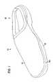
- FIG. 1is a perspective view of a slipper construction according to the principles of the invention wherein the contoured footbed has been removed.
- FIG. 2is a perspective, assembly view of an insole according to the principles of the invention prior to compression molding.
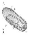
- FIG. 3is a perspective view of an insole according to the principles of the invention.
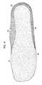
- FIG. 4is a bottom view of the insole of FIG. 3 .
- FIG. 5is a perspective, assembly view of the slipper construction of FIG. 1 .
- FIG. 6is a perspective view of an alternative embodiment of an insole according to the principles of the invention.
- FIGS. 7-10are perspective views of alternative embodiments of insoles according to the principles of the invention.
- FIG. 11is a perspective view of a closed back slipper according to the principles of the invention.
- FIG. 12is a side view of the closed back slipper of FIG. 11 .
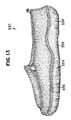
- FIG. 13is a side view of an alternative closed back slipper according to the principles of the invention.
- FIG. 14is a perspective view of an open back slipper according to the principles of the invention.
- FIG. 15is a perspective view of an open back slipper according to the principles of the invention.
- the slipper 10includes an outsole 12 , an upper 14 , and an insole 16 .
- the insole 16is removable from the insole receiving area 18 and is shown removed in FIGS. 1 and 5 .
- the slipper 10can be characterized as having a generally soft construction while providing support for a wearer's foot.
- the insole 16has a top surface 20 and a bottom surface 24 . As shown in FIG. 3 , the top surface 20 includes a contour design 22 in a heel cup region 23 . When the insole 16 is provided within the insole receiving area 18 , the contour design 22 is readily visible to someone looking at the slipper 10 . It is believed that the contour design 22 provides visual interest for a customer of the slipper and may cause the customer to examine the slipper 10 more closely. It is believed that customers will associate the contour design 22 with slippers having an insole according to the invention. In addition, the contour design 22 is believed to provide additional cushioning.
- the insole 16can be assembled by laminating a first layer 26 and a second layer 28 to provide a laminate construction 30 , and compression molding the laminate construction 30 .
- the first layer 26can be a foam layer 27
- the second layer 28can be a fabric layer 29 .
- the foam layer 27includes a first foam side 31 and a second foam side 32 .
- the fabric layer 29includes a first fabric side 33 and a second fabric side 34 .
- the fabric layer 29is placed over the foam layer 27 so that the second fabric side 34 is adjacent to the first foam side 31 .
- the fabric layer 29can be held in place on the foam layer 27 by an adhesive.
- Adhesivecan be applied as a dry powder adhesive, a hot melt adhesive, a water based adhesive, etc.
- compression moldingis a generally well known technique for molding to create a molded article. To the extent molding techniques other than compression molding can be used to prepare the insole according to the invention, those techniques can generally be referred to as “molding.”
- the foam layer 27can be prepared from any foam material that exhibits the desired level of support and resiliency that is appropriate for use as an insole. It should be understood that the characterization of the desired level of support and resiliency refers to properties after molding to provide the insole.
- An exemplary foam material that can be usedincludes ethylene vinyl acetate. A particular form of ethylene vinyl acetate that can be used is sponge ethylene vinyl acetate.
- the density of the foam layershould be sufficient to provide the desired level of support after the foam has been compression molded. If the foam density is too low, it is expected that insufficient support will be provided. If the foam density is too high, it is expected that the foam will be too rigid.
- a desirable foam density rangecan be between about 4 lb/ft 2 and about 10 lb/ft 2 prior to compression molding. In general, it is difficult to measure the density of the foam layer 27 after compression molding because different parts of the insole 16 can be compressed to different levels and thereby provide different densities.
- the fabric layer 29can be provided from any type of fabric material that adheres to the foam layer 27 and provides a desired surface texture.
- the fabric layercan be a woven material, a nonwoven material, or a knitted material. Because it is desirable for the contour design 22 to be visible, it is generally desirable for the fabric layer 29 to have a nap that is sufficiently small (if it exists at all) so it does not obscure the contour design 22 . In general, it is expected that the nap will be less than about 4 mm.
- An exemplary fabric material that can be usedincludes microfiber sueded fabric.
- An exemplary microfiber sueded fabricincludes a fabric prepared from polyester.
- the insole according to the inventioncan be provided without the fabric layer 29 . If there is no fabric layer 29 , the wearer's foot can directly contact the foam layer 27 . It is expected that the fabric layer, when present, can be selected to provide a desired feel against the wearer's foot.
- the insole 16additionally includes a retaining wall 36 and an arch support 38 .
- the contour design 22 , the retaining wall 36 , and the arch support 38can be formed during the compression molding step.
- the retaining wall 36extends along a portion of the insole perimeter 39 .
- the arch support 38extends along a portion of the insole perimeter in the region where arch support is desired.
- the insole 16includes three general regions. These regions include a heel region 40 , an arch region 42 , and a toe region 44 .
- the heel region 40includes that portion of the insole 16 that generally contains and supports the wearer's heel.
- the toe region 44includes that portion of the insole 16 that generally contains and supports the wearer's toes.
- the arch region 42is generally that portion of the insole 16 provided between the heel region 40 and the toe region 44 and provides support for the wearer's arch. It should be understood that there can be some degree of overlap between the regions.
- the heel region 40includes a heel cushioning area 46 and a heel perimeter 47
- the arch region 42includes, an arch cushioning area 48 and an arch perimeter 49
- the toe region 44includes a toe cushioning area 50 and a toe perimeter 51 .
- the cushioning areas 46 , 48 , and 50refer to the portions of the insole 16 that cushions the corresponding part of a wearer's foot
- the perimeters 47 , 49 , and 51refer to portions of the insole perimeter 39 of the insole 16 .
- the retaining wall 36extends around the heel perimeter 47 and into the arch perimeter 49 .
- the retaining wall 36does not extend into the toe perimeter 51 .
- the retaining wall 36is constructed so that it extends above the heel cushioning area top surface 52 and the arch cushioning area top surface 54 to an extent sufficient, to help retain the wearer's foot in its proper location on the insole 16 .
- the retaining wall 36can have a varying height depending upon whether it is located in the heel region 40 or the arch region 42 .
- the retaining wall 36can have a height that is sufficient for providing containment and/or support of the wearer's foot, but should not be so high that it causes discomfort.
- An exemplary range for the retaining wall 36can be between about 1 ⁇ 4 inch and about 1 inch. In many applications, it is expected that the retaining wall 36 will have a height of about 7 ⁇ 8 inch above the heel cushioning area top surface 52 and the arch cushioning area top surface 54 . Because it is expected that the toe region 44 will be compressed more than the heel region 40 and the arch region 42 , it is expected that the toe cushioning area top surface 56 will be lower than the heel cushioning area top surface 52 and the arch cushioning area top surface 54 . In addition, it should be understood that the retaining wall 36 can decrease until it merges with the arch cushioning area top surface 54 and/or the toe cushioning area top surface 56 .
- the combination of the heel cushioning area 46 and the retaining wall 36 provided in the heel perimeter 47provides a structure that can be referred to as the heel cup region 23 because it acts to contain the wearer's heel and keep it in a stationary position.
- the heel cushioning area 46includes the contour design 22 .
- the contour design 22provides additional cushioning.
- the contour design 22includes areas of relatively lower density foam 57 and areas of relatively higher density foam 58 .
- the contour design 22 shown in FIG. 3can be referred to as a starburst pattern 41 because it includes a relatively low density central area 59 surrounded by isolated domains of relatively low density foam 55 .
- the reference to low density foamrefers to the comparison with the adjacent areas of relatively higher density foam 58 .
- the difference in height between the lower density foam areas 57 and the higher density foam areas 58should be sufficient to be readily visible upon inspection of the insole 16 , but should not be so large as to cause discomfort. In general, it is expected that the difference in height between the low density area 57 and the higher density areas 58 will be between about 1/16 inch and about 3/16 inch.
- the contour designmay or may not be present in the heel cup region 23 , and may include various designs such as those of interest to customers.
- the upper 14is shown separated from the outsole 12 .
- the upper 14includes an outsole attachment area 60 , a foot covering area 62 , and a stabilizing member 64 .
- the outsole attachment area 60is provided along the upper 14 covering the length of attachment between the upper 14 and the outsole 12 .
- the outsole attachment area 60extends around the entire upper circumference 61 . That is, the outsole attachment area 60 extends to provide attachment to the outsole 12 in the toe region 63 , the arch region 65 , and the heel region 67 .
- the combination of the outsole attachment area 60 and the foot covering area 62 provided in the heel region 40can be referred to as the heel wrap upper 66 .
- the foot covering area 62includes an opening 68 that allows for the insertion of a foot into the foot receiving area 18 . Binding 69 can be provided along the foot covering area 62 to provide a finished appearance to the opening 68 .
- the stabilizing member 64is attached to the upper 14 along the outsole attachment area 60 .
- One technique for attaching the stabilizing member 64 along the outsole attachment area 60is by sewing to create a stitch line 70 and a seam allowance 72 .
- the upper 14can then be attached to the outsole 12 along the outsole retaining wall 74 to hide the stitch line 70 and the seam allowance 72 .
- the upper 14can be attached to the outsole 12 by stitching to create a stitch line 80 as shown in FIG. 1 .
- the outsole 12includes an outsole top side 82 , an outsole bottom side 84 , and an outsole retaining wall 74 .
- the outsole retaining wall 74extends above the outsole top side 82 along the perimeter 86 . It should be understood that the outsole can be provided having various configurations and can be prepared by various manufacturing techniques without any preference for particular materials and processes except to recognize that certain preferences may be based on various reasons including cost and customer preference.
- the upper 14can be prepared from any fabric material commonly used in the manufacture of a slipper.
- the stabilizing member 64can be provided from the same type of material used to provide the outsole attachment area 60 . In general, the stabilizing member 64 is provided to assist with the attachment of the upper 14 to the outsole 12 . The stabilizing member 64 helps the upper 14 maintain its shape during the step of attaching the upper 14 to the outsole 12 .
- the uppercan be attached to the outsole by stitching, it should be appreciated that other techniques can be used including adhesive bonding.
- the upper 14is shown attached to the outsole 12 along the entire perimeter 86 in the embodiment shown in FIG. 1 , alternatives can exist where the upper is not attached to the outsole in at least a portion of the perimeter.
- the insole, 90includes a plurality of perforations or holes 92 provided in the heel region 94 , a plurality of perforations 96 provided in the arch region 98 , and a plurality of perforations 100 provided in the toe region 102 .
- the perforationsprovide for additional air circulation in order to make the slipper more comfortable to a wearer.
- the presence of the perforations 96 in the arch support 104helps provide flexibility to the arch support 104 . In general, slippers are available in whole sizes, and slippers are generally not available in half sizes. Accordingly, by providing a more flexible arch support 104 , it is possible to provide the insole 90 with a larger degree of fit for various individuals.
- the insole according to the inventioncan be characterized as a removable, contoured footbed. That is, the insole is removable from the insole receiving area. It is expected that the insole may be glued in place within the insole receiving area to simply hold it in place until it is desired to remove the insole.
- the insolecan be glued in place within the insole receiving area by spot gluing or placing spots of glue between the insole and the stabilizing member.
- the insolecan be glued directly to the outsole.
- the insolecan be referred to as a footbed because of the presence of the retaining wall and the arch support.
- the insolecan be referred to as a contoured footbed because of the additional presence of the contour design. It is expected that the combination of the retaining wall and the arch support, when combined with the outsole retaining wall, will help stabilize a wearer's foot within the slipper.
- FIGS. 7-10alternative insoles according to the present invention are shown. It is pointed out that the insoles of FIGS. 7-10 are provided in U.S. application Ser. No. 29/165,183 that is incorporated herein by reference. Additional views of the insoles of FIGS. 7-10 can be found in U.S. application Ser. No. 29/165,183.
- the insole 200is shown having a plurality of perforations 220 in the heel region 202 , a plurality of perforations 222 in the arch region 204 , and a plurality of perforations 224 in the toe region 206 .
- the plurality of perforations 222include a plurality of perforations 223 in the arch support 214 and a plurality of perforations 225 in the arch region 204 that are not in the arch support 214 .
- the perforationsprovide air flow and in the case of perforations 223 , provide flexibility in the arch support 214 .
- the heel cup region 228 of the insole 200is shown without a contour design.
- the insole 200 ′includes a plurality of perforations 220 ′ in the heel region 202 ′, and does not include perforations in the arch region 204 ′ and the toe region 206 ′.
- the heel region 202 ′includes a contour design 229 ′ provided as a starburst pattern in the heel cup region 228 ′.
- the perforations 220 ′are shown within the central area of low density foam 231 ′ of the starburst pattern 233 ′ and not in the outlying areas of low density foam 235 ′ of the starburst pattern 233 ′.
- the perforationscan be provided in either or both of the central area of low density foam 231 ′ or the outlying areas of low density foam 235 ′.
- the insole 200 ′′includes perforations 220 ′′ in the heel region 202 ′′, and perforations 222 ′′ in the arch region 204 ′′.
- the insole 200 ′′′includes no perforations and includes a contour design 229 ′′′ in the heel cup region 228 ′′′.
- FIGS. 11-16are provided showing alternative slipper configurations that include representative examples of insole configurations.
- the slipper configurations shown in FIGS. 11-16can be found in U.S. application Ser. Nos. 29/165,186, 29/165,190, and 29/165,204 that are incorporated herein by reference.
- the various insole configurations according to the inventionsuch as those shown in FIGS. 3 and 6 , can be substituted for those insoles shown in FIGS. 11-16 .
- the slipper 300includes an insole 302 , an outsole 304 , and an upper 306 .
- the insole 302can be provided as an insole or footbed according to the principles of the invention.
- the slipper 300can be referred to as a closed back slipper because the upper 306 is constructed to include a heel wrap upper 308 that extends upward from the outsole 304 so that it wraps and encloses the wearer's heel.
- the upper 306additionally includes a foot covering area 310 that covers the top of the wearer's foot.
- the upper 306includes an opening through which the wearer's foot passes when taking on or off the slipper 300 .
- the upper 306can include elastic members 314 to help allow the wearer's foot to fit through the opening 312 by allowing a stretch between the foot top covering upper 316 and the side upper 318 .
- the outsole 304includes an outsole retaining wall 320 and the upper 306 is shown attached to the outsole retaining wall 320 along the outsole perimeter 322 . As shown in FIG. 12 , the outsole 304 can have an outsole retaining wall 320 having various configuration and styling as long as the upper is capable of attaching thereto.
- a slipper design according to the inventionis shown at reference number 330 .
- the slipper design 330is similar to the slipper design 300 except that the outsole 332 includes cuts 334 that are visible when viewing the outsole exterior surface 336 .
- the cutscan be provided in any desired design and can be provided to help increase flexibility and/or traction.
- the slippers 400 and 400 ′include an upper 402 and 402 ′, and an outsole 404 and 404 ′.
- the upper 402 and 402 ′include a heel wrap portion 406 and 406 ′ that is relatively low to the outsole. Because the heel wrap portion 406 and 406 ′ is so low, the slippers 400 and 400 ′ can be referred to as open back slippers. By providing open back slippers, it is generally easier to insert or remove a wearer's foot.
- the slipper design 450includes an upper 452 and an outsole 454 .
- the upper 452includes a heel wrap portion 456 that can be considered sufficiently low so that the slipper 450 can be referred to as an open back slipper.
- the upper 452includes an opening 458 above the location of the wearer's toes. Accordingly, the slipper 450 can be referred to as an open toe slipper.
- the upper 452includes a toe wrap upper 460 that attaches to the outsole 454 in the toe area 462 .
- the slipper 450includes an insole 470 that is provided within the insole receiving area 472 .
Landscapes
- Health & Medical Sciences (AREA)
- Epidemiology (AREA)
- General Health & Medical Sciences (AREA)
- Public Health (AREA)
- Chemical & Material Sciences (AREA)
- Engineering & Computer Science (AREA)
- Materials Engineering (AREA)
- Footwear And Its Accessory, Manufacturing Method And Apparatuses (AREA)
Abstract
Description
Claims (30)
Priority Applications (4)
| Application Number | Priority Date | Filing Date | Title |
|---|---|---|---|
| CA002493762ACA2493762A1 (en) | 2002-08-05 | 2003-08-05 | Slipper insert, slipper, and method for manufacturing a slipper |
| AU2003263984AAU2003263984A1 (en) | 2002-08-05 | 2003-08-05 | Slipper insert, slipper, and method for manufacturing a slipper |
| US10/634,508US6931763B2 (en) | 2002-08-05 | 2003-08-05 | Slipper insole, slipper, and method for manufacturing a slipper |
| PCT/US2003/024409WO2004012545A1 (en) | 2002-08-05 | 2003-08-05 | Slipper insert, slipper, and method for manufacturing a slipper |
Applications Claiming Priority (2)
| Application Number | Priority Date | Filing Date | Title |
|---|---|---|---|
| US10/213,276US6990754B2 (en) | 2002-08-05 | 2002-08-05 | Slipper insole, slipper, and method for manufacturing a slipper |
| US10/634,508US6931763B2 (en) | 2002-08-05 | 2003-08-05 | Slipper insole, slipper, and method for manufacturing a slipper |
Related Parent Applications (1)
| Application Number | Title | Priority Date | Filing Date |
|---|---|---|---|
| US10/213,276Continuation-In-PartUS6990754B2 (en) | 2002-08-05 | 2002-08-05 | Slipper insole, slipper, and method for manufacturing a slipper |
Publications (2)
| Publication Number | Publication Date |
|---|---|
| US20040134095A1 US20040134095A1 (en) | 2004-07-15 |
| US6931763B2true US6931763B2 (en) | 2005-08-23 |
Family
ID=56290466
Family Applications (1)
| Application Number | Title | Priority Date | Filing Date |
|---|---|---|---|
| US10/634,508Expired - Fee RelatedUS6931763B2 (en) | 2002-08-05 | 2003-08-05 | Slipper insole, slipper, and method for manufacturing a slipper |
Country Status (1)
| Country | Link |
|---|---|
| US (1) | US6931763B2 (en) |
Cited By (16)
| Publication number | Priority date | Publication date | Assignee | Title |
|---|---|---|---|---|
| US20050257401A1 (en)* | 2002-05-03 | 2005-11-24 | Elefanten Gmbh | Insole |
| US20060130366A1 (en)* | 2002-08-05 | 2006-06-22 | R.G. Barry Corporation | Slipper insole, slipper, and method for manufacturing a slipper |
| US20070033835A1 (en)* | 2005-08-02 | 2007-02-15 | Bray Walter T Jr | Insole arrangement; footwear with insole arrangement; and, method of preparation |
| US20080072461A1 (en)* | 2006-09-21 | 2008-03-27 | Howlett Harold A | Cushioned orthotic |
| US20080086908A1 (en)* | 2006-10-16 | 2008-04-17 | Nike, Inc. | Article of Footwear with Deforming Insert |
| US20130031809A1 (en)* | 2011-08-05 | 2013-02-07 | Roses & Rye LLC | Shoe having improved podiatric support |
| US8621765B2 (en) | 2008-12-09 | 2014-01-07 | Red Wing Shoe Company, Inc. | Molded insole for welted footwear |
| US20140259757A1 (en)* | 2013-03-18 | 2014-09-18 | Fusco Industrial Corporation | Arch Support Insole for Shoes |
| US20150026999A1 (en)* | 2011-06-15 | 2015-01-29 | Propet Global Limited | Customizable Shoe Insole |
| WO2016133992A1 (en)* | 2015-02-17 | 2016-08-25 | R.G. Barry Corporation | Insole, slipper and method for manufacturing a slipper |
| US20170340052A1 (en)* | 2013-08-13 | 2017-11-30 | Heel-It, Llc | Orthotic Insert Device |
| US9943131B1 (en)* | 2014-07-31 | 2018-04-17 | Lacrosse Footwear, Inc. | Footwear airflow system |
| US20210085020A1 (en)* | 2019-09-20 | 2021-03-25 | R. G. Barry Corporation | Footwear article including cushion management system |
| US11134863B2 (en) | 2015-10-05 | 2021-10-05 | Scholl's Wellness Company Llc | Generating orthotic product recommendations |
| US11854058B2 (en) | 2017-10-13 | 2023-12-26 | Scholl's Wellness Company Llc | Footcare product dispensing kiosk |
| USD1054194S1 (en)* | 2022-11-02 | 2024-12-17 | Zappos IP LLC | Footwear |
Families Citing this family (8)
| Publication number | Priority date | Publication date | Assignee | Title |
|---|---|---|---|---|
| KR101851260B1 (en)* | 2016-08-25 | 2018-04-23 | 박문환 | A Sole having a Dual Structure |
| US20180235827A1 (en)* | 2017-02-21 | 2018-08-23 | Jeffrey S. Rich | Foot orthotic |
| ES2681128B1 (en)* | 2017-03-09 | 2019-06-19 | Gutierrez Fuentes Jose Maria | PROCEDURE FOR THE MANUFACTURE OF A FELT FLOOR FOR FOOTWEAR AND PRODUCTS ASI OBTAINED |
| WO2019160170A1 (en)* | 2018-02-13 | 2019-08-22 | 박문환 | Shoe sole having double structure |
| US11633008B2 (en)* | 2021-07-27 | 2023-04-25 | Shimano Inc. | Shoe |
| USD974715S1 (en)* | 2022-09-07 | 2023-01-10 | Jiangfu Lin | Shoe |
| USD975410S1 (en)* | 2022-09-08 | 2023-01-17 | Jiangfu Lin | Shoe |
| US20240251911A1 (en)* | 2024-03-08 | 2024-08-01 | Vijay Shamdasani | Recovery Footwear |
Citations (55)
| Publication number | Priority date | Publication date | Assignee | Title |
|---|---|---|---|---|
| USRE18237E (en) | 1927-10-29 | 1931-10-27 | Island | |
| US2715285A (en) | 1952-02-19 | 1955-08-16 | Vecchio Angelo Del | Laminated sole structure |
| US3468040A (en) | 1967-12-13 | 1969-09-23 | Tatuo Fukuoka | Sandals |
| US3766669A (en) | 1969-08-21 | 1973-10-23 | Usm Corp | Profiled cellular article |
| US4020569A (en) | 1975-05-01 | 1977-05-03 | Tatsuo Fukuoka | Sole of a footwear |
| US4020570A (en) | 1975-10-10 | 1977-05-03 | Hiraoka New York, Inc. | Cushioned insole for footwear such as shoes, boots, or the like |
| US4033054A (en) | 1975-08-11 | 1977-07-05 | Tatsuo Fukuoka | Footwear |
| US4124946A (en) | 1976-04-02 | 1978-11-14 | Scholl, Inc. | Built-in insole and article of footwear containing same |
| US4129697A (en) | 1976-02-24 | 1978-12-12 | Bayer Aktiengesellschaft | Process for the production of thermoformable polyisocyanurate foams |
| USD276003S (en) | 1982-05-24 | 1984-10-23 | Mcabery Robert | Slipper |
| US4508774A (en) | 1983-03-15 | 1985-04-02 | Basf Aktiengesellschaft | Cellular, molded polyurethane parts, process for their preparation by thermoforming of polyester-urethane foam and their use |
| US4513518A (en) | 1982-09-30 | 1985-04-30 | Rogers Foam Corporation | Shoe inner sole |
| USD284901S (en) | 1984-05-17 | 1986-08-05 | Tilles Harvey G | Insole for shoes used in lateral sports |
| US4627177A (en) | 1984-07-02 | 1986-12-09 | Meyers Stuart R | Insole structure |
| US4633877A (en) | 1984-08-07 | 1987-01-06 | Duramet Systems, Inc. | Dynamic foot support and kit therefor |
| US4674204A (en) | 1983-02-28 | 1987-06-23 | Sullivan James B | Shock absorbing innersole and method for preparing same |
| USD294537S (en) | 1986-12-08 | 1988-03-08 | Reebok International Ltd. | Shoe sole |
| US4741951A (en) | 1987-01-29 | 1988-05-03 | Reeves Bros., Inc. | Method for forming thermoformable polyurethane foam articles |
| US4760655A (en) | 1986-07-07 | 1988-08-02 | Walter Mauch | Insole |
| US4864740A (en) | 1986-12-22 | 1989-09-12 | Kimberly-Clark Corporation | Disposable hygienic shoe insole and method for making the same |
| US5146698A (en) | 1989-05-08 | 1992-09-15 | Tilles Harvey G | Shoe insole proform II |
| US5167999A (en) | 1991-06-18 | 1992-12-01 | Wang Sui Mu | Liquid cushioning means |
| US5203793A (en) | 1989-09-20 | 1993-04-20 | Lyden Robert M | Conformable cushioning and stability device for articles of footwear |
| USD354389S (en) | 1993-05-05 | 1995-01-17 | Schering-Plough Healthcare Products, Inc. | Sports insole with perforations |
| USD354844S (en) | 1993-09-30 | 1995-01-31 | Dixie Rinehart | Shoe |
| US5392532A (en) | 1993-10-18 | 1995-02-28 | R. G. Barry Corporation | Slipper having an insole attached to a peripheral outsole wall |
| US5435077A (en) | 1994-04-18 | 1995-07-25 | The United States Shoe Corporation | Layered cushioning system for shoe soles |
| USD366140S (en) | 1994-06-29 | 1996-01-16 | Amasia International, Ltd. | Shoe sock lining |
| US5483757A (en) | 1994-02-03 | 1996-01-16 | Frykberg; Robert G. | Healing sandal |
| USD366956S (en) | 1994-12-21 | 1996-02-13 | Schering-Plough Healthcare Products, Inc. | Work boot insole |
| US5542196A (en)* | 1994-04-15 | 1996-08-06 | Donna Karan Shoe Company | Insole |
| US5544432A (en) | 1993-12-28 | 1996-08-13 | Mizuno Corporation | Insole for shoes providing heel stabilization |
| US5551173A (en) | 1995-03-16 | 1996-09-03 | Chambers; Mark D. | Comfort insole |
| US5611153A (en) | 1994-05-12 | 1997-03-18 | Schering-Plough Healthcare Products, Inc. | Insole for heel pain relief |
| US5664342A (en) | 1992-03-04 | 1997-09-09 | Prodomo S.A. | Insole with flexible massaging knobs |
| US5669162A (en) | 1996-03-07 | 1997-09-23 | Brown Group, Inc. | Cushion insert |
| US5675914A (en) | 1995-11-13 | 1997-10-14 | The Rockport Company, Inc. | Air circulating footbed |
| US5718064A (en) | 1994-04-04 | 1998-02-17 | Nine West Group Inc. | Multi-layer sole construction for walking shoes |
| US5787608A (en) | 1996-07-30 | 1998-08-04 | Greenawalt; Kent S. | Custom-made footwear |
| USD399042S (en) | 1996-06-04 | 1998-10-06 | Sara Lee Corporation | Shoe insole |
| USD418281S (en) | 1998-05-11 | 2000-01-04 | R. G. Barry Corporation | Open toe slipper |
| USD423766S (en) | 1999-10-07 | 2000-05-02 | Sherry Genga | High heel inset |
| USD426373S (en) | 1997-05-21 | 2000-06-13 | Acushnet Company | Foot-bed |
| USD432769S (en) | 1999-07-26 | 2000-10-31 | Wu-Bin Yung | Insole |
| US6176025B1 (en)* | 1999-05-28 | 2001-01-23 | Spalding Sports Worldwide, Inc. | Cushioning system for golf shoes |
| US6219941B1 (en) | 1999-09-14 | 2001-04-24 | Jay J. Kukoff | Foot massaging shoe insole and method of making same |
| US6226894B1 (en) | 1998-05-11 | 2001-05-08 | R. G. Barry Corporation | Slipper and method for manufacturing slipper |
| US6286232B1 (en) | 2000-01-28 | 2001-09-11 | Schering-Plough Healthcare, Inc. | Pregnancy/maternity insoles |
| US6338768B1 (en)* | 2000-07-07 | 2002-01-15 | Cheng-Te Chi | Method for manufacturing a shoe insole |
| US6418642B1 (en) | 2000-01-11 | 2002-07-16 | R. G. Barry Corporation | Slipper with polymer insole jell and method for manufacturing |
| US6662469B2 (en)* | 2001-10-31 | 2003-12-16 | Wolverine World Wide, Inc. | Footwear construction and method for manufacturing same |
| USD485665S1 (en) | 2002-08-05 | 2004-01-27 | R.G. Barry Corporation | Open toe slipper with contoured footbed |
| USD485666S1 (en) | 2002-08-05 | 2004-01-27 | R.G. Barry Corporation | Closed toe slipper with contoured footbed |
| USD485664S1 (en) | 2002-08-05 | 2004-01-27 | R. G. Barry Corporation | Closed back slipper with contoured footbed |
| USD490970S1 (en) | 2002-08-05 | 2004-06-08 | R. G. Barry Corporation | Contoured footbed |
Family Cites Families (17)
| Publication number | Priority date | Publication date | Assignee | Title |
|---|---|---|---|---|
| US62779A (en)* | 1867-03-12 | Improvement in teavelling-bacfs | ||
| US366956A (en)* | 1887-07-19 | Process of | ||
| US276003A (en)* | 1883-04-17 | Island | ||
| US64599A (en)* | 1867-05-07 | Improvement in heating-stoves | ||
| US426373A (en)* | 1890-04-22 | Territory | ||
| US423769A (en)* | 1890-03-18 | Belt-coupling | ||
| US174475A (en)* | 1876-03-07 | Improvement in attaching pump-barrels to their bases | ||
| US18237A (en)* | 1857-09-22 | Edge-plane fob trimming boot and shoe soles | ||
| US120316A (en)* | 1871-10-24 | Improvement in brakes for railway-cars | ||
| US354389A (en)* | 1886-12-14 | Cultivator | ||
| US366140A (en)* | 1887-07-05 | Clevis | ||
| US170768A (en)* | 1875-12-07 | Improvement in screw-cutting dies | ||
| US135347A (en)* | 1873-01-28 | Improvement in exeroising-machines | ||
| US119742A (en)* | 1871-10-10 | Improvement in devices for raising sunken vessels | ||
| US399042A (en)* | 1889-03-05 | And richard a | ||
| US423766A (en)* | 1890-03-18 | Corn-harvester | ||
| US294537A (en)* | 1884-03-04 | Mandrel for cable-presses |
- 2003
- 2003-08-05USUS10/634,508patent/US6931763B2/ennot_activeExpired - Fee Related
Patent Citations (55)
| Publication number | Priority date | Publication date | Assignee | Title |
|---|---|---|---|---|
| USRE18237E (en) | 1927-10-29 | 1931-10-27 | Island | |
| US2715285A (en) | 1952-02-19 | 1955-08-16 | Vecchio Angelo Del | Laminated sole structure |
| US3468040A (en) | 1967-12-13 | 1969-09-23 | Tatuo Fukuoka | Sandals |
| US3766669A (en) | 1969-08-21 | 1973-10-23 | Usm Corp | Profiled cellular article |
| US4020569A (en) | 1975-05-01 | 1977-05-03 | Tatsuo Fukuoka | Sole of a footwear |
| US4033054A (en) | 1975-08-11 | 1977-07-05 | Tatsuo Fukuoka | Footwear |
| US4020570A (en) | 1975-10-10 | 1977-05-03 | Hiraoka New York, Inc. | Cushioned insole for footwear such as shoes, boots, or the like |
| US4129697A (en) | 1976-02-24 | 1978-12-12 | Bayer Aktiengesellschaft | Process for the production of thermoformable polyisocyanurate foams |
| US4124946A (en) | 1976-04-02 | 1978-11-14 | Scholl, Inc. | Built-in insole and article of footwear containing same |
| USD276003S (en) | 1982-05-24 | 1984-10-23 | Mcabery Robert | Slipper |
| US4513518A (en) | 1982-09-30 | 1985-04-30 | Rogers Foam Corporation | Shoe inner sole |
| US4674204A (en) | 1983-02-28 | 1987-06-23 | Sullivan James B | Shock absorbing innersole and method for preparing same |
| US4508774A (en) | 1983-03-15 | 1985-04-02 | Basf Aktiengesellschaft | Cellular, molded polyurethane parts, process for their preparation by thermoforming of polyester-urethane foam and their use |
| USD284901S (en) | 1984-05-17 | 1986-08-05 | Tilles Harvey G | Insole for shoes used in lateral sports |
| US4627177A (en) | 1984-07-02 | 1986-12-09 | Meyers Stuart R | Insole structure |
| US4633877A (en) | 1984-08-07 | 1987-01-06 | Duramet Systems, Inc. | Dynamic foot support and kit therefor |
| US4760655A (en) | 1986-07-07 | 1988-08-02 | Walter Mauch | Insole |
| USD294537S (en) | 1986-12-08 | 1988-03-08 | Reebok International Ltd. | Shoe sole |
| US4864740A (en) | 1986-12-22 | 1989-09-12 | Kimberly-Clark Corporation | Disposable hygienic shoe insole and method for making the same |
| US4741951A (en) | 1987-01-29 | 1988-05-03 | Reeves Bros., Inc. | Method for forming thermoformable polyurethane foam articles |
| US5146698A (en) | 1989-05-08 | 1992-09-15 | Tilles Harvey G | Shoe insole proform II |
| US5203793A (en) | 1989-09-20 | 1993-04-20 | Lyden Robert M | Conformable cushioning and stability device for articles of footwear |
| US5167999A (en) | 1991-06-18 | 1992-12-01 | Wang Sui Mu | Liquid cushioning means |
| US5664342A (en) | 1992-03-04 | 1997-09-09 | Prodomo S.A. | Insole with flexible massaging knobs |
| USD354389S (en) | 1993-05-05 | 1995-01-17 | Schering-Plough Healthcare Products, Inc. | Sports insole with perforations |
| USD354844S (en) | 1993-09-30 | 1995-01-31 | Dixie Rinehart | Shoe |
| US5392532A (en) | 1993-10-18 | 1995-02-28 | R. G. Barry Corporation | Slipper having an insole attached to a peripheral outsole wall |
| US5544432A (en) | 1993-12-28 | 1996-08-13 | Mizuno Corporation | Insole for shoes providing heel stabilization |
| US5483757A (en) | 1994-02-03 | 1996-01-16 | Frykberg; Robert G. | Healing sandal |
| US5718064A (en) | 1994-04-04 | 1998-02-17 | Nine West Group Inc. | Multi-layer sole construction for walking shoes |
| US5542196A (en)* | 1994-04-15 | 1996-08-06 | Donna Karan Shoe Company | Insole |
| US5435077A (en) | 1994-04-18 | 1995-07-25 | The United States Shoe Corporation | Layered cushioning system for shoe soles |
| US5611153A (en) | 1994-05-12 | 1997-03-18 | Schering-Plough Healthcare Products, Inc. | Insole for heel pain relief |
| USD366140S (en) | 1994-06-29 | 1996-01-16 | Amasia International, Ltd. | Shoe sock lining |
| USD366956S (en) | 1994-12-21 | 1996-02-13 | Schering-Plough Healthcare Products, Inc. | Work boot insole |
| US5551173A (en) | 1995-03-16 | 1996-09-03 | Chambers; Mark D. | Comfort insole |
| US5675914A (en) | 1995-11-13 | 1997-10-14 | The Rockport Company, Inc. | Air circulating footbed |
| US5669162A (en) | 1996-03-07 | 1997-09-23 | Brown Group, Inc. | Cushion insert |
| USD399042S (en) | 1996-06-04 | 1998-10-06 | Sara Lee Corporation | Shoe insole |
| US5787608A (en) | 1996-07-30 | 1998-08-04 | Greenawalt; Kent S. | Custom-made footwear |
| USD426373S (en) | 1997-05-21 | 2000-06-13 | Acushnet Company | Foot-bed |
| USD418281S (en) | 1998-05-11 | 2000-01-04 | R. G. Barry Corporation | Open toe slipper |
| US6226894B1 (en) | 1998-05-11 | 2001-05-08 | R. G. Barry Corporation | Slipper and method for manufacturing slipper |
| US6176025B1 (en)* | 1999-05-28 | 2001-01-23 | Spalding Sports Worldwide, Inc. | Cushioning system for golf shoes |
| USD432769S (en) | 1999-07-26 | 2000-10-31 | Wu-Bin Yung | Insole |
| US6219941B1 (en) | 1999-09-14 | 2001-04-24 | Jay J. Kukoff | Foot massaging shoe insole and method of making same |
| USD423766S (en) | 1999-10-07 | 2000-05-02 | Sherry Genga | High heel inset |
| US6418642B1 (en) | 2000-01-11 | 2002-07-16 | R. G. Barry Corporation | Slipper with polymer insole jell and method for manufacturing |
| US6286232B1 (en) | 2000-01-28 | 2001-09-11 | Schering-Plough Healthcare, Inc. | Pregnancy/maternity insoles |
| US6338768B1 (en)* | 2000-07-07 | 2002-01-15 | Cheng-Te Chi | Method for manufacturing a shoe insole |
| US6662469B2 (en)* | 2001-10-31 | 2003-12-16 | Wolverine World Wide, Inc. | Footwear construction and method for manufacturing same |
| USD485665S1 (en) | 2002-08-05 | 2004-01-27 | R.G. Barry Corporation | Open toe slipper with contoured footbed |
| USD485666S1 (en) | 2002-08-05 | 2004-01-27 | R.G. Barry Corporation | Closed toe slipper with contoured footbed |
| USD485664S1 (en) | 2002-08-05 | 2004-01-27 | R. G. Barry Corporation | Closed back slipper with contoured footbed |
| USD490970S1 (en) | 2002-08-05 | 2004-06-08 | R. G. Barry Corporation | Contoured footbed |
Non-Patent Citations (1)
| Title |
|---|
| Declaration of Walter Thomas Bray, Jr. including Exhibits A-I (Color Photographs). |
Cited By (22)
| Publication number | Priority date | Publication date | Assignee | Title |
|---|---|---|---|---|
| US20050257401A1 (en)* | 2002-05-03 | 2005-11-24 | Elefanten Gmbh | Insole |
| US7266913B2 (en)* | 2002-05-03 | 2007-09-11 | Dosenbach-Ochsner Ag Schuhe Und Sport | Insole |
| US20060130366A1 (en)* | 2002-08-05 | 2006-06-22 | R.G. Barry Corporation | Slipper insole, slipper, and method for manufacturing a slipper |
| US7331125B2 (en) | 2002-08-05 | 2008-02-19 | R.G. Barry Corporation | Slipper insole, slipper, and method for manufacturing a slipper |
| US7805858B2 (en) | 2002-08-05 | 2010-10-05 | R.G. Barry Corporation | Slipper insole, slipper, and method for manufacturing a slipper |
| US20070033835A1 (en)* | 2005-08-02 | 2007-02-15 | Bray Walter T Jr | Insole arrangement; footwear with insole arrangement; and, method of preparation |
| US20080072461A1 (en)* | 2006-09-21 | 2008-03-27 | Howlett Harold A | Cushioned orthotic |
| US7958653B2 (en)* | 2006-09-21 | 2011-06-14 | Schering-Plough Healthcare Products, Inc. | Cushioned orthotic |
| US8800169B2 (en) | 2006-09-21 | 2014-08-12 | Msd Consumer Care, Inc. | Cushioned orthotic |
| US20080086908A1 (en)* | 2006-10-16 | 2008-04-17 | Nike, Inc. | Article of Footwear with Deforming Insert |
| US8621765B2 (en) | 2008-12-09 | 2014-01-07 | Red Wing Shoe Company, Inc. | Molded insole for welted footwear |
| US20150026999A1 (en)* | 2011-06-15 | 2015-01-29 | Propet Global Limited | Customizable Shoe Insole |
| US20130031809A1 (en)* | 2011-08-05 | 2013-02-07 | Roses & Rye LLC | Shoe having improved podiatric support |
| US20140259757A1 (en)* | 2013-03-18 | 2014-09-18 | Fusco Industrial Corporation | Arch Support Insole for Shoes |
| US20170340052A1 (en)* | 2013-08-13 | 2017-11-30 | Heel-It, Llc | Orthotic Insert Device |
| US9943131B1 (en)* | 2014-07-31 | 2018-04-17 | Lacrosse Footwear, Inc. | Footwear airflow system |
| WO2016133992A1 (en)* | 2015-02-17 | 2016-08-25 | R.G. Barry Corporation | Insole, slipper and method for manufacturing a slipper |
| US11134863B2 (en) | 2015-10-05 | 2021-10-05 | Scholl's Wellness Company Llc | Generating orthotic product recommendations |
| US11854058B2 (en) | 2017-10-13 | 2023-12-26 | Scholl's Wellness Company Llc | Footcare product dispensing kiosk |
| US20210085020A1 (en)* | 2019-09-20 | 2021-03-25 | R. G. Barry Corporation | Footwear article including cushion management system |
| US12082651B2 (en)* | 2019-09-20 | 2024-09-10 | R. G. Barry Corporation | Footwear article including cushion management system |
| USD1054194S1 (en)* | 2022-11-02 | 2024-12-17 | Zappos IP LLC | Footwear |
Also Published As
| Publication number | Publication date |
|---|---|
| US20040134095A1 (en) | 2004-07-15 |
Similar Documents
| Publication | Publication Date | Title |
|---|---|---|
| EP1526786B1 (en) | Slipper insert, slipper, and method for manufacturing a slipper | |
| US6931763B2 (en) | Slipper insole, slipper, and method for manufacturing a slipper | |
| US6976319B2 (en) | Footwear construction | |
| US8209884B2 (en) | Outside Opanka shoe construction | |
| US7353626B2 (en) | Shoe with slip-resistant, shape-retaining fabric outsole | |
| US7757408B2 (en) | Shoe having improved Opanka stitching | |
| JPH01268502A (en) | Shoes | |
| US6477792B2 (en) | Method of manufacturing a composite vapor-permeable insole and insole thus obtained | |
| US20130212908A1 (en) | Article of Footwear with Detachable Upper and Lower Designs | |
| US20020088145A1 (en) | Shoe construction | |
| US20080244934A1 (en) | Method And Apparatus For A Shoe With Improved Construction | |
| US20110214310A1 (en) | Shoe chassis | |
| US6112432A (en) | Insole, footwear, and method for manufacturing footwear | |
| US20030106171A1 (en) | Comfort moccasin | |
| US20130318817A1 (en) | Footwear with integrated energy wave sockliner | |
| US6877253B2 (en) | Method and apparatus for providing a shoe using San Crispino and vulcanization constructions | |
| CN219047551U (en) | Commercial shoes without hook cores | |
| JPH10225301A (en) | Shoes and making thereof | |
| WO2016133994A1 (en) | Slipper and method for manufacturing a slipper | |
| CA2822618A1 (en) | Footwear with integrated energy wave sockliner | |
| JP3104143U (en) | Sandals with split insole | |
| JP2024008443A (en) | Inner sole and shoes | |
| JPS60841B2 (en) | Method for manufacturing slippers with concave insole | |
| JP3072290U (en) | Outsole of indoor footwear | |
| WO2016133992A1 (en) | Insole, slipper and method for manufacturing a slipper |
Legal Events
| Date | Code | Title | Description |
|---|---|---|---|
| AS | Assignment | Owner name:R. G. BARRY CORPORATION, OHIO Free format text:ASSIGNMENT OF ASSIGNORS INTEREST;ASSIGNORS:BRAY JR., THOMAS;STEWART, THERESA;REEL/FRAME:015133/0252 Effective date:20040304 | |
| FPAY | Fee payment | Year of fee payment:4 | |
| REMI | Maintenance fee reminder mailed | ||
| LAPS | Lapse for failure to pay maintenance fees | ||
| STCH | Information on status: patent discontinuation | Free format text:PATENT EXPIRED DUE TO NONPAYMENT OF MAINTENANCE FEES UNDER 37 CFR 1.362 | |
| FP | Lapsed due to failure to pay maintenance fee | Effective date:20130823 | |
| AS | Assignment | Owner name:GCI CAPITAL MARKETS LLC, AS FIRST LIEN AGENT, NEW Free format text:SECURITY INTEREST;ASSIGNOR:R. G. BARRY CORPORATION;REEL/FRAME:033683/0258 Effective date:20140903 | |
| AS | Assignment | Owner name:PNC BANK, NATIONAL ASSOCIATION, AS AGENT, NEW JERS Free format text:SECURITY INTEREST;ASSIGNOR:R.G. BARRY CORPORATION, AS SUCCESSOR TO MERGER TO MRVK MERGER CO.;REEL/FRAME:033679/0549 Effective date:20140903 | |
| AS | Assignment | Owner name:GCI CAPITAL MARKETS LLC, AS SECOND LIEN AGENT, NEW Free format text:SECURITY INTEREST;ASSIGNOR:R. G. BARRY CORPORATION;REEL/FRAME:033698/0544 Effective date:20140903 | |
| AS | Assignment | Owner name:PNC BANK, NATIONAL ASSOCIATION, PENNSYLVANIA Free format text:SECURITY INTEREST;ASSIGNOR:R.G. BARRY CORPORATION;REEL/FRAME:046559/0269 Effective date:20180802 | |
| AS | Assignment | Owner name:R. G. BARRY CORPORATION, OHIO Free format text:RELEASE BY SECURED PARTY;ASSIGNOR:GOLUB CAPITAL MARKETS LLC;REEL/FRAME:046571/0636 Effective date:20180802 Owner name:R. G. BARRY CORPORATION, OHIO Free format text:RELEASE BY SECURED PARTY;ASSIGNOR:GOLUB CAPITAL MARKETS LLC;REEL/FRAME:046571/0678 Effective date:20180802 | |
| AS | Assignment | Owner name:R.G. BARRY CORPORATION, OHIO Free format text:RELEASE BY SECURED PARTY;ASSIGNOR:PNC BANK, NATIONAL ASSOCIATION;REEL/FRAME:062581/0841 Effective date:20230111 |