US6931328B2 - Analyte detection system with software download capabilities - Google Patents
Analyte detection system with software download capabilitiesDownload PDFInfo
- Publication number
- US6931328B2 US6931328B2US10/291,908US29190802AUS6931328B2US 6931328 B2US6931328 B2US 6931328B2US 29190802 AUS29190802 AUS 29190802AUS 6931328 B2US6931328 B2US 6931328B2
- Authority
- US
- United States
- Prior art keywords
- analyte
- detection system
- sample
- analyte detection
- computer
- Prior art date
- Legal status (The legal status is an assumption and is not a legal conclusion. Google has not performed a legal analysis and makes no representation as to the accuracy of the status listed.)
- Expired - Lifetime
Links
- 239000012491analyteSubstances0.000titleclaimsabstractdescription199
- 238000001514detection methodMethods0.000titleclaimsabstractdescription119
- 238000012544monitoring processMethods0.000claimsabstractdescription31
- 230000006854communicationEffects0.000claimsabstractdescription23
- 238000004891communicationMethods0.000claimsabstractdescription23
- 238000000034methodMethods0.000claimsdescription109
- 238000005259measurementMethods0.000claimsdescription63
- 230000003287optical effectEffects0.000claimsdescription39
- 230000005855radiationEffects0.000claimsdescription32
- 238000004422calculation algorithmMethods0.000claimsdescription16
- 238000004364calculation methodMethods0.000claimsdescription7
- 230000007175bidirectional communicationEffects0.000claims2
- 239000000523sampleSubstances0.000description177
- 239000010410layerSubstances0.000description159
- 239000000463materialSubstances0.000description74
- 238000001816coolingMethods0.000description65
- 239000008280bloodSubstances0.000description55
- 210000004027cellAnatomy0.000description28
- 230000008569processEffects0.000description21
- 238000010438heat treatmentMethods0.000description19
- 238000012545processingMethods0.000description18
- 210000004369bloodAnatomy0.000description14
- 238000012360testing methodMethods0.000description14
- 238000004458analytical methodMethods0.000description13
- 238000002835absorbanceMethods0.000description11
- 238000000576coating methodMethods0.000description11
- 230000005670electromagnetic radiationEffects0.000description11
- XLYOFNOQVPJJNP-UHFFFAOYSA-NwaterSubstancesOXLYOFNOQVPJJNP-UHFFFAOYSA-N0.000description10
- 238000013459approachMethods0.000description9
- 239000011248coating agentSubstances0.000description9
- 239000012530fluidSubstances0.000description9
- 230000006870functionEffects0.000description9
- 230000004044responseEffects0.000description9
- 210000001519tissueAnatomy0.000description9
- WQZGKKKJIJFFOK-GASJEMHNSA-NGlucoseNatural productsOC[C@H]1OC(O)[C@H](O)[C@@H](O)[C@@H]1OWQZGKKKJIJFFOK-GASJEMHNSA-N0.000description8
- PXHVJJICTQNCMI-UHFFFAOYSA-NNickelChemical compound[Ni]PXHVJJICTQNCMI-UHFFFAOYSA-N0.000description8
- 239000008103glucoseSubstances0.000description8
- 238000010521absorption reactionMethods0.000description7
- 230000008901benefitEffects0.000description7
- 239000000306componentSubstances0.000description7
- 230000007423decreaseEffects0.000description7
- PCHJSUWPFVWCPO-UHFFFAOYSA-NgoldChemical compound[Au]PCHJSUWPFVWCPO-UHFFFAOYSA-N0.000description7
- 229910052737goldInorganic materials0.000description7
- 239000010931goldSubstances0.000description7
- -1polypropylenePolymers0.000description7
- 239000000126substanceSubstances0.000description7
- 210000001124body fluidAnatomy0.000description6
- 239000003623enhancerSubstances0.000description6
- 210000003722extracellular fluidAnatomy0.000description6
- 230000007246mechanismEffects0.000description6
- BASFCYQUMIYNBI-UHFFFAOYSA-NplatinumChemical compound[Pt]BASFCYQUMIYNBI-UHFFFAOYSA-N0.000description6
- 230000035945sensitivityEffects0.000description6
- XUIMIQQOPSSXEZ-UHFFFAOYSA-NSiliconChemical compound[Si]XUIMIQQOPSSXEZ-UHFFFAOYSA-N0.000description5
- 230000009471actionEffects0.000description5
- 230000005540biological transmissionEffects0.000description5
- 229910003460diamondInorganic materials0.000description5
- 239000010432diamondSubstances0.000description5
- 230000000694effectsEffects0.000description5
- 239000002547new drugSubstances0.000description5
- 210000003296salivaAnatomy0.000description5
- 229910052710siliconInorganic materials0.000description5
- 239000010703siliconSubstances0.000description5
- IJGRMHOSHXDMSA-UHFFFAOYSA-NAtomic nitrogenChemical compoundN#NIJGRMHOSHXDMSA-UHFFFAOYSA-N0.000description4
- BPYKTIZUTYGOLE-IFADSCNNSA-NBilirubinChemical compoundN1C(=O)C(C)=C(C=C)\C1=C\C1=C(C)C(CCC(O)=O)=C(CC2=C(C(C)=C(\C=C/3C(=C(C=C)C(=O)N\3)C)N2)CCC(O)=O)N1BPYKTIZUTYGOLE-IFADSCNNSA-N0.000description4
- CURLTUGMZLYLDI-UHFFFAOYSA-NCarbon dioxideChemical compoundO=C=OCURLTUGMZLYLDI-UHFFFAOYSA-N0.000description4
- LFQSCWFLJHTTHZ-UHFFFAOYSA-NEthanolChemical compoundCCOLFQSCWFLJHTTHZ-UHFFFAOYSA-N0.000description4
- 108010054147HemoglobinsProteins0.000description4
- 102000001554HemoglobinsHuman genes0.000description4
- 229910000661Mercury cadmium tellurideInorganic materials0.000description4
- 239000004743PolypropyleneSubstances0.000description4
- GWEVSGVZZGPLCZ-UHFFFAOYSA-NTitan oxideChemical compoundO=[Ti]=OGWEVSGVZZGPLCZ-UHFFFAOYSA-N0.000description4
- 239000000853adhesiveSubstances0.000description4
- 230000001070adhesive effectEffects0.000description4
- 229910045601alloyInorganic materials0.000description4
- 239000000956alloySubstances0.000description4
- 229910052782aluminiumInorganic materials0.000description4
- XAGFODPZIPBFFR-UHFFFAOYSA-NaluminiumChemical compound[Al]XAGFODPZIPBFFR-UHFFFAOYSA-N0.000description4
- MCMSPRNYOJJPIZ-UHFFFAOYSA-Ncadmium;mercury;telluriumChemical compound[Cd]=[Te]=[Hg]MCMSPRNYOJJPIZ-UHFFFAOYSA-N0.000description4
- 210000002421cell wallAnatomy0.000description4
- 238000006243chemical reactionMethods0.000description4
- HVYWMOMLDIMFJA-DPAQBDIFSA-NcholesterolChemical compoundC1C=C2C[C@@H](O)CC[C@]2(C)[C@@H]2[C@@H]1[C@@H]1CC[C@H]([C@H](C)CCCC(C)C)[C@@]1(C)CC2HVYWMOMLDIMFJA-DPAQBDIFSA-N0.000description4
- 239000004020conductorSubstances0.000description4
- DDRJAANPRJIHGJ-UHFFFAOYSA-NcreatinineChemical compoundCN1CC(=O)NC1=NDDRJAANPRJIHGJ-UHFFFAOYSA-N0.000description4
- 238000010586diagramMethods0.000description4
- 239000003814drugSubstances0.000description4
- 210000000245forearmAnatomy0.000description4
- NOESYZHRGYRDHS-UHFFFAOYSA-NinsulinChemical compoundN1C(=O)C(NC(=O)C(CCC(N)=O)NC(=O)C(CCC(O)=O)NC(=O)C(C(C)C)NC(=O)C(NC(=O)CN)C(C)CC)CSSCC(C(NC(CO)C(=O)NC(CC(C)C)C(=O)NC(CC=2C=CC(O)=CC=2)C(=O)NC(CCC(N)=O)C(=O)NC(CC(C)C)C(=O)NC(CCC(O)=O)C(=O)NC(CC(N)=O)C(=O)NC(CC=2C=CC(O)=CC=2)C(=O)NC(CSSCC(NC(=O)C(C(C)C)NC(=O)C(CC(C)C)NC(=O)C(CC=2C=CC(O)=CC=2)NC(=O)C(CC(C)C)NC(=O)C(C)NC(=O)C(CCC(O)=O)NC(=O)C(C(C)C)NC(=O)C(CC(C)C)NC(=O)C(CC=2NC=NC=2)NC(=O)C(CO)NC(=O)CNC2=O)C(=O)NCC(=O)NC(CCC(O)=O)C(=O)NC(CCCNC(N)=N)C(=O)NCC(=O)NC(CC=3C=CC=CC=3)C(=O)NC(CC=3C=CC=CC=3)C(=O)NC(CC=3C=CC(O)=CC=3)C(=O)NC(C(C)O)C(=O)N3C(CCC3)C(=O)NC(CCCCN)C(=O)NC(C)C(O)=O)C(=O)NC(CC(N)=O)C(O)=O)=O)NC(=O)C(C(C)CC)NC(=O)C(CO)NC(=O)C(C(C)O)NC(=O)C1CSSCC2NC(=O)C(CC(C)C)NC(=O)C(NC(=O)C(CCC(N)=O)NC(=O)C(CC(N)=O)NC(=O)C(NC(=O)C(N)CC=1C=CC=CC=1)C(C)C)CC1=CN=CN1NOESYZHRGYRDHS-UHFFFAOYSA-N0.000description4
- 230000003993interactionEffects0.000description4
- 229910052759nickelInorganic materials0.000description4
- 230000000737periodic effectEffects0.000description4
- 230000002093peripheral effectEffects0.000description4
- 229920001155polypropylenePolymers0.000description4
- 239000011241protective layerSubstances0.000description4
- 238000005476solderingMethods0.000description4
- 238000003860storageMethods0.000description4
- 238000012546transferMethods0.000description4
- 210000002700urineAnatomy0.000description4
- 229910001369BrassInorganic materials0.000description3
- 229910001374InvarInorganic materials0.000description3
- 239000004698PolyethyleneSubstances0.000description3
- RTAQQCXQSZGOHL-UHFFFAOYSA-NTitaniumChemical compound[Ti]RTAQQCXQSZGOHL-UHFFFAOYSA-N0.000description3
- 230000003667anti-reflective effectEffects0.000description3
- 239000010951brassSubstances0.000description3
- 239000000470constituentSubstances0.000description3
- 230000000875corresponding effectEffects0.000description3
- 238000000151depositionMethods0.000description3
- 230000008021depositionEffects0.000description3
- 238000000338in vitroMethods0.000description3
- 238000001727in vivoMethods0.000description3
- 229910010272inorganic materialInorganic materials0.000description3
- 239000011147inorganic materialSubstances0.000description3
- 230000002452interceptive effectEffects0.000description3
- 229910052751metalInorganic materials0.000description3
- 239000002184metalSubstances0.000description3
- 239000011368organic materialSubstances0.000description3
- TWNQGVIAIRXVLR-UHFFFAOYSA-Noxo(oxoalumanyloxy)alumaneChemical compoundO=[Al]O[Al]=OTWNQGVIAIRXVLR-UHFFFAOYSA-N0.000description3
- 229910052697platinumInorganic materials0.000description3
- 229920000573polyethylenePolymers0.000description3
- 239000011253protective coatingSubstances0.000description3
- 239000010935stainless steelSubstances0.000description3
- 229910001220stainless steelInorganic materials0.000description3
- 239000013589supplementSubstances0.000description3
- 230000001360synchronised effectEffects0.000description3
- 239000010936titaniumSubstances0.000description3
- 229910052719titaniumInorganic materials0.000description3
- PFNQVRZLDWYSCW-UHFFFAOYSA-N(fluoren-9-ylideneamino) n-naphthalen-1-ylcarbamateChemical compoundC12=CC=CC=C2C2=CC=CC=C2C1=NOC(=O)NC1=CC=CC2=CC=CC=C12PFNQVRZLDWYSCW-UHFFFAOYSA-N0.000description2
- 102000009027AlbuminsHuman genes0.000description2
- 108010088751AlbuminsProteins0.000description2
- 208000004434CalcinosisDiseases0.000description2
- OKTJSMMVPCPJKN-UHFFFAOYSA-NCarbonChemical compound[C]OKTJSMMVPCPJKN-UHFFFAOYSA-N0.000description2
- 108010003320CarboxyhemoglobinProteins0.000description2
- RYGMFSIKBFXOCR-UHFFFAOYSA-NCopperChemical compound[Cu]RYGMFSIKBFXOCR-UHFFFAOYSA-N0.000description2
- 102000018832CytochromesHuman genes0.000description2
- 108010052832CytochromesProteins0.000description2
- 102000004877InsulinHuman genes0.000description2
- 108090001061InsulinProteins0.000description2
- 102000004895LipoproteinsHuman genes0.000description2
- 108090001030LipoproteinsProteins0.000description2
- 229920004779ULTEM® 2300Polymers0.000description2
- XSQUKJJJFZCRTK-UHFFFAOYSA-NUreaChemical compoundNC(N)=OXSQUKJJJFZCRTK-UHFFFAOYSA-N0.000description2
- 238000004164analytical calibrationMethods0.000description2
- QVGXLLKOCUKJST-UHFFFAOYSA-Natomic oxygenChemical compound[O]QVGXLLKOCUKJST-UHFFFAOYSA-N0.000description2
- 230000003190augmentative effectEffects0.000description2
- WQZGKKKJIJFFOK-VFUOTHLCSA-Nbeta-D-glucoseChemical compoundOC[C@H]1O[C@@H](O)[C@H](O)[C@@H](O)[C@@H]1OWQZGKKKJIJFFOK-VFUOTHLCSA-N0.000description2
- 239000013060biological fluidSubstances0.000description2
- 239000012503blood componentSubstances0.000description2
- 239000004202carbamideSubstances0.000description2
- 229910052799carbonInorganic materials0.000description2
- 229910002092carbon dioxideInorganic materials0.000description2
- 239000001569carbon dioxideSubstances0.000description2
- 235000012000cholesterolNutrition0.000description2
- 239000012141concentrateSubstances0.000description2
- 239000002826coolantSubstances0.000description2
- 229910052802copperInorganic materials0.000description2
- 239000010949copperSubstances0.000description2
- 229940109239creatinineDrugs0.000description2
- 230000001419dependent effectEffects0.000description2
- 235000014113dietary fatty acidsNutrition0.000description2
- 229940079593drugDrugs0.000description2
- 210000003743erythrocyteAnatomy0.000description2
- 239000000194fatty acidSubstances0.000description2
- 229930195729fatty acidNatural products0.000description2
- 150000004665fatty acidsChemical class0.000description2
- 229910052732germaniumInorganic materials0.000description2
- GNPVGFCGXDBREM-UHFFFAOYSA-Ngermanium atomChemical compound[Ge]GNPVGFCGXDBREM-UHFFFAOYSA-N0.000description2
- 239000011521glassSubstances0.000description2
- 229940088597hormoneDrugs0.000description2
- 239000005556hormoneSubstances0.000description2
- 229910052739hydrogenInorganic materials0.000description2
- 229940125396insulinDrugs0.000description2
- 210000002977intracellular fluidAnatomy0.000description2
- 150000002500ionsChemical class0.000description2
- 150000002576ketonesChemical class0.000description2
- 210000000265leukocyteAnatomy0.000description2
- 238000012423maintenanceMethods0.000description2
- 238000004519manufacturing processMethods0.000description2
- 238000000691measurement methodMethods0.000description2
- 238000012986modificationMethods0.000description2
- 230000004048modificationEffects0.000description2
- 238000012806monitoring deviceMethods0.000description2
- 229910052757nitrogenInorganic materials0.000description2
- 230000008520organizationEffects0.000description2
- 229910052760oxygenInorganic materials0.000description2
- 239000001301oxygenSubstances0.000description2
- 239000012782phase change materialSubstances0.000description2
- 102000004169proteins and genesHuman genes0.000description2
- 108090000623proteins and genesProteins0.000description2
- 230000002829reductive effectEffects0.000description2
- 230000000717retained effectEffects0.000description2
- 230000003595spectral effectEffects0.000description2
- 210000004243sweatAnatomy0.000description2
- 239000004408titanium dioxideSubstances0.000description2
- WFKWXMTUELFFGS-UHFFFAOYSA-NtungstenChemical compound[W]WFKWXMTUELFFGS-UHFFFAOYSA-N0.000description2
- 229910052721tungstenInorganic materials0.000description2
- 239000010937tungstenSubstances0.000description2
- 230000000007visual effectEffects0.000description2
- JBRZTFJDHDCESZ-UHFFFAOYSA-NAsGaChemical compound[As]#[Ga]JBRZTFJDHDCESZ-UHFFFAOYSA-N0.000description1
- 229910001020Au alloyInorganic materials0.000description1
- 238000012935AveragingMethods0.000description1
- BVKZGUZCCUSVTD-UHFFFAOYSA-MBicarbonateChemical compoundOC([O-])=OBVKZGUZCCUSVTD-UHFFFAOYSA-M0.000description1
- VEXZGXHMUGYJMC-UHFFFAOYSA-MChloride anionChemical compound[Cl-]VEXZGXHMUGYJMC-UHFFFAOYSA-M0.000description1
- VYZAMTAEIAYCRO-UHFFFAOYSA-NChromiumChemical compound[Cr]VYZAMTAEIAYCRO-UHFFFAOYSA-N0.000description1
- 239000004593EpoxySubstances0.000description1
- 229910001218Gallium arsenideInorganic materials0.000description1
- DGAQECJNVWCQMB-PUAWFVPOSA-MIlexoside XXIXChemical compoundC[C@@H]1CC[C@@]2(CC[C@@]3(C(=CC[C@H]4[C@]3(CC[C@@H]5[C@@]4(CC[C@@H](C5(C)C)OS(=O)(=O)[O-])C)C)[C@@H]2[C@]1(C)O)C)C(=O)O[C@H]6[C@@H]([C@H]([C@@H]([C@H](O6)CO)O)O)O.[Na+]DGAQECJNVWCQMB-PUAWFVPOSA-M0.000description1
- 241001465754MetazoaSpecies0.000description1
- ZLMJMSJWJFRBEC-UHFFFAOYSA-NPotassiumChemical compound[K]ZLMJMSJWJFRBEC-UHFFFAOYSA-N0.000description1
- 235000011449RosaNutrition0.000description1
- FGNOVNMCFCLRNZ-UHFFFAOYSA-N[Ge].[As].[Se]Chemical compound[Ge].[As].[Se]FGNOVNMCFCLRNZ-UHFFFAOYSA-N0.000description1
- 230000002159abnormal effectEffects0.000description1
- 238000005299abrasionMethods0.000description1
- 239000002313adhesive filmSubstances0.000description1
- 239000006117anti-reflective coatingSubstances0.000description1
- 238000003491arrayMethods0.000description1
- 230000000712assemblyEffects0.000description1
- 238000000429assemblyMethods0.000description1
- 238000010009beatingMethods0.000description1
- 230000006399behaviorEffects0.000description1
- 230000017531blood circulationEffects0.000description1
- 239000010839body fluidSubstances0.000description1
- QHFQAJHNDKBRBO-UHFFFAOYSA-Lcalcium chloride hexahydrateChemical compoundO.O.O.O.O.O.[Cl-].[Cl-].[Ca+2]QHFQAJHNDKBRBO-UHFFFAOYSA-L0.000description1
- 238000005266castingMethods0.000description1
- 230000001413cellular effectEffects0.000description1
- 229910010293ceramic materialInorganic materials0.000description1
- 230000008859changeEffects0.000description1
- 238000005234chemical depositionMethods0.000description1
- 239000013626chemical specieSubstances0.000description1
- 229910052804chromiumInorganic materials0.000description1
- 239000011651chromiumSubstances0.000description1
- 150000001875compoundsChemical class0.000description1
- 238000004590computer programMethods0.000description1
- 230000008602contractionEffects0.000description1
- 238000007796conventional methodMethods0.000description1
- 230000002596correlated effectEffects0.000description1
- 238000002109crystal growth methodMethods0.000description1
- 229910021419crystalline siliconInorganic materials0.000description1
- 238000005520cutting processMethods0.000description1
- 125000004122cyclic groupChemical group0.000description1
- 230000001351cycling effectEffects0.000description1
- 230000003247decreasing effectEffects0.000description1
- 230000007812deficiencyEffects0.000description1
- 238000011161developmentMethods0.000description1
- 238000006073displacement reactionMethods0.000description1
- 230000002500effect on skinEffects0.000description1
- 239000003792electrolyteSubstances0.000description1
- 238000011156evaluationMethods0.000description1
- 230000001747exhibiting effectEffects0.000description1
- 238000001914filtrationMethods0.000description1
- 239000007789gasSubstances0.000description1
- 239000011213glass-filled polymerSubstances0.000description1
- 239000003353gold alloySubstances0.000description1
- 230000036541healthEffects0.000description1
- 238000002513implantationMethods0.000description1
- 238000010030laminatingMethods0.000description1
- 230000000670limiting effectEffects0.000description1
- 239000007788liquidSubstances0.000description1
- 230000007774longtermEffects0.000description1
- 235000012054mealsNutrition0.000description1
- 239000012528membraneSubstances0.000description1
- 150000002739metalsChemical class0.000description1
- 238000002044microwave spectrumMethods0.000description1
- 238000002156mixingMethods0.000description1
- 239000000203mixtureSubstances0.000description1
- 229910052755nonmetalInorganic materials0.000description1
- 150000002843nonmetalsChemical class0.000description1
- 238000010606normalizationMethods0.000description1
- 230000036961partial effectEffects0.000description1
- 239000002245particleSubstances0.000description1
- 230000035515penetrationEffects0.000description1
- 238000007747platingMethods0.000description1
- 229920000642polymerPolymers0.000description1
- 229910052700potassiumInorganic materials0.000description1
- 239000011591potassiumSubstances0.000description1
- 238000002310reflectometryMethods0.000description1
- 238000011160researchMethods0.000description1
- 150000003839saltsChemical class0.000description1
- 238000005070samplingMethods0.000description1
- 238000006748scratchingMethods0.000description1
- 230000002393scratching effectEffects0.000description1
- 229940065287selenium compoundDrugs0.000description1
- 239000004065semiconductorSubstances0.000description1
- 230000011664signalingEffects0.000description1
- 238000005245sinteringMethods0.000description1
- 229910052708sodiumInorganic materials0.000description1
- 239000011734sodiumSubstances0.000description1
- 239000007787solidSubstances0.000description1
- 238000012306spectroscopic techniqueMethods0.000description1
- 238000001228spectrumMethods0.000description1
- 238000007920subcutaneous administrationMethods0.000description1
- 229910052717sulfurInorganic materials0.000description1
- 230000002123temporal effectEffects0.000description1
- 239000002470thermal conductorSubstances0.000description1
- 230000036962time dependentEffects0.000description1
- 230000001960triggered effectEffects0.000description1
- 238000002604ultrasonographyMethods0.000description1
- 238000007740vapor depositionMethods0.000description1
- 238000012795verificationMethods0.000description1
- 238000001429visible spectrumMethods0.000description1
- 239000002918waste heatSubstances0.000description1
- 230000003313weakening effectEffects0.000description1
Images


Classifications
- A—HUMAN NECESSITIES
- A61—MEDICAL OR VETERINARY SCIENCE; HYGIENE
- A61B—DIAGNOSIS; SURGERY; IDENTIFICATION
- A61B5/00—Measuring for diagnostic purposes; Identification of persons
- A61B5/145—Measuring characteristics of blood in vivo, e.g. gas concentration or pH-value ; Measuring characteristics of body fluids or tissues, e.g. interstitial fluid or cerebral tissue
- A61B5/1495—Calibrating or testing of in-vivo probes
- A—HUMAN NECESSITIES
- A61—MEDICAL OR VETERINARY SCIENCE; HYGIENE
- A61B—DIAGNOSIS; SURGERY; IDENTIFICATION
- A61B5/00—Measuring for diagnostic purposes; Identification of persons
- A61B5/0002—Remote monitoring of patients using telemetry, e.g. transmission of vital signals via a communication network
- A—HUMAN NECESSITIES
- A61—MEDICAL OR VETERINARY SCIENCE; HYGIENE
- A61B—DIAGNOSIS; SURGERY; IDENTIFICATION
- A61B5/00—Measuring for diagnostic purposes; Identification of persons
- A61B5/145—Measuring characteristics of blood in vivo, e.g. gas concentration or pH-value ; Measuring characteristics of body fluids or tissues, e.g. interstitial fluid or cerebral tissue
- A61B5/14532—Measuring characteristics of blood in vivo, e.g. gas concentration or pH-value ; Measuring characteristics of body fluids or tissues, e.g. interstitial fluid or cerebral tissue for measuring glucose, e.g. by tissue impedance measurement
- A—HUMAN NECESSITIES
- A61—MEDICAL OR VETERINARY SCIENCE; HYGIENE
- A61B—DIAGNOSIS; SURGERY; IDENTIFICATION
- A61B5/00—Measuring for diagnostic purposes; Identification of persons
- A61B5/145—Measuring characteristics of blood in vivo, e.g. gas concentration or pH-value ; Measuring characteristics of body fluids or tissues, e.g. interstitial fluid or cerebral tissue
- A61B5/1455—Measuring characteristics of blood in vivo, e.g. gas concentration or pH-value ; Measuring characteristics of body fluids or tissues, e.g. interstitial fluid or cerebral tissue using optical sensors, e.g. spectral photometrical oximeters
- G—PHYSICS
- G16—INFORMATION AND COMMUNICATION TECHNOLOGY [ICT] SPECIALLY ADAPTED FOR SPECIFIC APPLICATION FIELDS
- G16H—HEALTHCARE INFORMATICS, i.e. INFORMATION AND COMMUNICATION TECHNOLOGY [ICT] SPECIALLY ADAPTED FOR THE HANDLING OR PROCESSING OF MEDICAL OR HEALTHCARE DATA
- G16H40/00—ICT specially adapted for the management or administration of healthcare resources or facilities; ICT specially adapted for the management or operation of medical equipment or devices
- G16H40/40—ICT specially adapted for the management or administration of healthcare resources or facilities; ICT specially adapted for the management or operation of medical equipment or devices for the management of medical equipment or devices, e.g. scheduling maintenance or upgrades
- G—PHYSICS
- G16—INFORMATION AND COMMUNICATION TECHNOLOGY [ICT] SPECIALLY ADAPTED FOR SPECIFIC APPLICATION FIELDS
- G16H—HEALTHCARE INFORMATICS, i.e. INFORMATION AND COMMUNICATION TECHNOLOGY [ICT] SPECIALLY ADAPTED FOR THE HANDLING OR PROCESSING OF MEDICAL OR HEALTHCARE DATA
- G16H40/00—ICT specially adapted for the management or administration of healthcare resources or facilities; ICT specially adapted for the management or operation of medical equipment or devices
- G16H40/60—ICT specially adapted for the management or administration of healthcare resources or facilities; ICT specially adapted for the management or operation of medical equipment or devices for the operation of medical equipment or devices
- G16H40/63—ICT specially adapted for the management or administration of healthcare resources or facilities; ICT specially adapted for the management or operation of medical equipment or devices for the operation of medical equipment or devices for local operation
- A—HUMAN NECESSITIES
- A61—MEDICAL OR VETERINARY SCIENCE; HYGIENE
- A61B—DIAGNOSIS; SURGERY; IDENTIFICATION
- A61B2560/00—Constructional details of operational features of apparatus; Accessories for medical measuring apparatus
- A61B2560/02—Operational features
- A61B2560/0266—Operational features for monitoring or limiting apparatus function
- A61B2560/0271—Operational features for monitoring or limiting apparatus function using a remote monitoring unit
- A—HUMAN NECESSITIES
- A61—MEDICAL OR VETERINARY SCIENCE; HYGIENE
- A61B—DIAGNOSIS; SURGERY; IDENTIFICATION
- A61B2562/00—Details of sensors; Constructional details of sensor housings or probes; Accessories for sensors
- A61B2562/02—Details of sensors specially adapted for in-vivo measurements
- A61B2562/0295—Strip shaped analyte sensors for apparatus classified in A61B5/145 or A61B5/157
- Y—GENERAL TAGGING OF NEW TECHNOLOGICAL DEVELOPMENTS; GENERAL TAGGING OF CROSS-SECTIONAL TECHNOLOGIES SPANNING OVER SEVERAL SECTIONS OF THE IPC; TECHNICAL SUBJECTS COVERED BY FORMER USPC CROSS-REFERENCE ART COLLECTIONS [XRACs] AND DIGESTS
- Y10—TECHNICAL SUBJECTS COVERED BY FORMER USPC
- Y10S—TECHNICAL SUBJECTS COVERED BY FORMER USPC CROSS-REFERENCE ART COLLECTIONS [XRACs] AND DIGESTS
- Y10S707/00—Data processing: database and file management or data structures
- Y10S707/99941—Database schema or data structure
- Y10S707/99944—Object-oriented database structure
- Y10S707/99945—Object-oriented database structure processing
Definitions
- This inventionpertains, in certain embodiments, to medical equipment for measuring blood analyte levels, and more particularly to a blood analyte measuring instrument having internet-based communication features.
- a patienthaving been taught how to use an existing portable analyte monitor is generally required thereafter to independently conduct and record his or her own measurements. Furthermore, the patient typically is required to both record and assess the measurements without benefit from a practitioner or supervising authority. Numerous errors can arise from these unsupervised procedures that may result in serious health risks for patients which knowingly, or inadvertently, are not in compliance with medical directives.
- patients using an analyte monitorare given a schedule of measurements they are required to take and a notebook in which to record the measurements. Patients often forget, or in some instances forego, conducting and correctly recording their analyte levels as measured by the instrument. If patients skip a measurement they may even elect to write down a “likely” number in the notebook as if such a measurement had been taken. Patient interaction with such a manual analyte monitoring instrument therefore provides no assurance of correct measurement and recordation. Furthermore, patients in a myriad of situations may require additional information and assistance with regard to the use and maintenance of their analyte measurement instrument.
- a measuring instrumentmay require periodic calibration or software updates. Assuring calibration compliance on instruments or updating the instrument's software in the field is burdensome.
- an analyte monitoring systemthat encourages patient compliance and facilitates equipment calibration and software updates.
- the present inventionin certain embodiments, satisfies those needs, as well as others, and overcomes deficiencies in current monitoring systems and procedures.
- the present inventionis an analyte measuring device with remote communications capabilities.
- a data linkis provided between the equipment and a centralized station, or server.
- the centralized stationcan monitor important information, such as: equipment calibration, the diligence of a patient taking and recording measurements according to a schedule, whether a software update is needed and the actual measurements taken by the patient.
- the centralized stationis preferably capable of forwarding information to the patient's physician for evaluation.
- the centralized stationcan have optional capability of locking out the patient if the patient has not paid his or her bills.
- the informationis communicated from the analyte measuring device directly to the physician.
- the centralized stationcan determine an update status of the analyte measuring device's software and automatically send a software update to the analyte measuring device.
- the preferred embodimentslink the monitoring activities performed by the patient and the assessment of those activities by the physician while reducing the chance of human error introduced into the long-term monitoring and treatment process.
- a non-invasive subsurface spectrophotometer instrument equipped with a communications linktakes the analyte measurements and communicates them over a network, such as the internet.
- the spectrophotometer instrumentcomprises data communication circuitry, such as dial-up circuitry, and additional session control protocols which integrate a number of the functions within the instrument for communication over a network connection.
- a destination site, or sites, on the networkare configured to receive information from the instrument and to transmit information and services.
- an analyte concentration monitoring systemcomprises an analyte detection system having a processor that calculates analyte concentration in accordance with software executable by the processor.
- the monitoring systemfurther comprises a network interface that is configured to provide connectivity to a computer.
- the analyte detection systemis configured to receive an update to the software from the computer.
- a method of automatically updating software on an analyte detection systemcomprises connecting an analyte detection system to a computer via a network, and checking, in the computer, an update status of software included in the analyte detection system. The method further comprises sending, when the update status indicates that a software update is needed, the software update to the analyte detection system via the network without intervention from a user. The method further comprises updating, in the analyte detection system, the software with the software update.
- an analyte concentration monitoring systemcomprises an analyte detection system comprising a processor, a software, and a network interface.
- the processoris configured to calculate analyte concentration in accordance to the software
- the network interfaceis configured to provide connectivity to a computer.
- the analyte detection systemis configured to update the software according to instructions from the computer.
- a method of automatically updating software on an analyte detection systemcomprises connecting an analyte detection system to a computer via a network.
- the methodfurther comprises checking, in the computer, an update status of software included in the analyte detection system.
- the methodfurther comprises encrypting, when the update status indicates that a software update is needed, the software update and sending the software update to the analyte detection system via the network.
- the methodfurther comprises updating, in the analyte detection system, the software with the software update.
- FIG. 1is a schematic view of a noninvasive optical detection system.
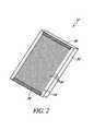
- FIG. 2is a perspective view of a window assembly for use with the noninvasive detection system.
- FIG. 2Ais a plan view of another embodiment of a window assembly for use with the noninvasive detection system.
- FIG. 3is an exploded schematic view of another embodiment of a window assembly for use with the noninvasive detection system.
- FIG. 4is a plan view of the window assembly connected to a cooling system.
- FIG. 5is a plan view of the window assembly connected to a cold reservoir.
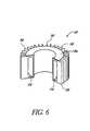
- FIG. 6is a cutaway view of a heat sink for use with the noninvasive detection system.
- FIG. 6Ais a cutaway perspective view of a lower portion of the noninvasive detection system of FIG. 1 .
- FIG. 6Bis an exploded perspective view of a window mounting system for use with the noninvasive optical detection system.
- FIG. 6Cis a partial plan view of the window mounting system of FIG. 6 B.
- FIG. 6Dis a sectional view of the window mounting system of FIG. 6 C.
- FIG. 7is a schematic view of a control system for use with the noninvasive optical detection system.
- FIG. 8depicts a first methodology for determining the concentration of an analyte interest.
- FIG. 9depicts a second methodology for determining the concentration of an analyte of interest.
- FIG. 10depicts a third methodology for determining the concentration of an analyte of interest.
- FIG. 11depicts a fourth methodology for determining the concentration of an analyte of interest.
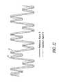
- FIG. 12depicts a fifth methodology for determining the concentration of an analyte of interest.
- FIG. 13is a schematic view of a reagentless whole-blood detection system.
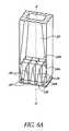
- FIG. 14is a perspective view of one embodiment of a cuvette for use with the reagentless whole-blood detection system.
- FIG. 15is a plan view of another embodiment of a cuvette for use with the reagentless whole-blood detection system.
- FIG. 16is a disassembled plan view of the cuvette shown in FIG. 15 .
- FIG. 16Ais an exploded perspective view of the cuvette of FIG. 15 .
- FIG. 17is a side view of the cuvette of FIG. 15 .
- FIG. 18is a functional block diagram showing an analyte monitoring system with network connectivity.
- FIG. 19is a block diagram of the electronic circuits within the analyte monitoring system of FIG. 18 .
- FIG. 20is a flowchart exemplifying calibration lockout according to one embodiment disclosed herein.
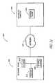
- FIG. 21is a block diagram of components of an analyte monitoring system having software update capabilities.
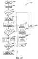
- FIG. 22is a flowchart exemplifying updating a analyte monitoring device's software according to another embodiment disclosed herein.
- Part Icontains a description of a number of analyte detection systems, including a noninvasive system and a whole-blood system, as well as associated methods of analyte detection.
- Parts II and IIIincludes a discussion of further systems and methods for, inter alia, updating software executed by analyte detection systems such as (but not limited to) those described in Part I. Accordingly, the systems and methods described in Parts II and III may (but need not) be employed by, within and/or in connection with those described in Part I.
- analyte detection systemsincluding a noninvasive system discussed largely in part A below and a whole-blood system discussed largely in part B below.
- various methodsincluding methods for detecting the concentration of an analyte in a material sample.
- Both the noninvasive system/method and the whole-blood system/methodcan employ optical measurement.
- opticalis a broad term and is used in its ordinary sense and refers, without limitation, to identification of the presence or concentration of an analyte in a material sample without requiring a chemical reaction to take place.
- the two approacheseach can operate independently to perform an optical analysis of a material sample.
- the two approachescan also be combined in an apparatus, or the two approaches can be used together to perform different steps of a method.
- the two approachesare combined to perform calibration of an apparatus, e.g., of an apparatus that employs a noninvasive approach.
- an advantageous combination of the two approachesperforms an invasive measurement to achieve greater accuracy and a whole-blood measurement to minimize discomfort to the patient.
- the whole-blood techniquemay be more accurate than the noninvasive technique at certain times of the day, e.g., at certain times after a meal has been consumed, or after a drug has been administered.
- any of the disclosed devicesmay be operated in accordance with any suitable detection methodology, and that any disclosed method may be employed in the operation of any suitable device.
- the disclosed devices and methodsare applicable in a wide variety of situations or modes of operation, including but not limited to invasive, noninvasive, intermittent or continuous measurement, subcutaneous implantation, wearable detection systems, or any combination thereof.
- FIG. 1depicts a noninvasive optical detection system (hereinafter “noninvasive system”) 10 in a presently preferred configuration.
- the depicted noninvasive system 10is particularly suited for noninvasively detecting the concentration of an analyte in a material sample S, by observing the infrared energy emitted by the sample, as will be discussed in further detail below.
- noninvasiveis a broad term and is used in its ordinary sense and refers, without limitation, to analyte detection devices and methods which have the capability to determine the concentration of an analyte in in-vivo tissue samples or bodily fluids. It should be understood, however, that the noninvasive system 10 disclosed herein is not limited to noninvasive use, as the noninvasive system 10 may be employed to analyze an in-vitro fluid or tissue sample which has been obtained invasively or noninvasively.
- invasiveor, alternatively, “traditional” is a broad term and is used in its ordinary sense and refers, without limitation, to analyte detection methods which involve the removal of fluid samples through the skin.
- the term “material sample”is a broad term and is used in its ordinary sense and refers, without limitation, to any collection of material which is suitable for analysis by the noninvasive system 10 .
- the material sample Smay comprise a tissue sample, such as a human forearm, placed against the noninvasive system 10 .
- the material sample Smay also comprise a volume of a bodily fluid, such as whole blood, blood component(s), interstitial fluid or intercellular fluid obtained invasively, or saliva or urine obtained noninvasively, or any collection of organic or inorganic material.
- analyteis a broad term and is used in its ordinary sense and refers, without limitation, to any chemical species the presence or concentration of which is sought in the material sample S by the noninvasive system 10 .
- the analyte(s) which may be detected by the noninvasive system 10include but not are limited to glucose, ethanol, insulin, water, carbon dioxide, blood oxygen, cholesterol, bilirubin, ketones, fatty acids, lipoproteins, albumin, urea, creatinine, white blood cells, red blood cells, hemoglobin, oxygenated hemoglobin, carboxyhemoglobin, organic molecules, inorganic molecules, pharmaceuticals, cytochrome, various proteins and chromophores, microcalcifications, electrolytes, sodium, potassium, chloride, bicarbonate, and hormones.
- the term “continuous”is a broad term and is used in its ordinary sense and refers, without limitation, to the taking of discrete measurements more frequently than about once every 10 minutes, and/or the taking of a stream or series of measurements or other data over any suitable time interval, for example, over an interval of one to several seconds, minutes, hours, days, or longer.
- the term “intermittent”is a broad term and is used in its ordinary sense and refers, without limitation, to the taking of measurements less frequently than about once every 10 minutes.
- the noninvasive system 10preferably comprises a window assembly 12 , although in some embodiments the window assembly 12 may be omitted.
- One function of the window assembly 12is to permit infrared energy E to enter the noninvasive system 10 from the sample S when it is placed against an upper surface 12 . of the window assembly 12 .
- the window assembly 12includes a heater layer (see discussion below) which is employed to heat the material sample S and stimulate emission of infrared energy therefrom.
- a cooling system 14preferably comprising a Peltier-type thermoelectric device, is in thermally conductive relation to the window assembly 12 so that the temperature of the window assembly 12 and the material sample S can be manipulated in accordance with a detection methodology discussed in greater detail below.
- the cooling system 14includes a cold surface 14 a which is in thermally conductive relation to a cold reservoir 16 and the window assembly 12 , and a hot surface 14 b which is in thermally conductive relation to a heat sink 18 .
- the infrared energy EAs the infrared energy E enters the noninvasive system 10 , it first passes through the window assembly 12 , then through an optical mixer 20 , and then through a collimator 22 .
- the optical mixer 20preferably comprises a light pipe having highly reflective inner surfaces which randomize the directionality of the infrared energy E as it passes therethrough and reflects against the mixer walls.
- the collimator 22also comprises a light pipe having highly-reflective inner walls, but the walls diverge as they extend away from the mixer 20 . The divergent walls cause the infrared energy E to tend to straighten as it advances toward the wider end of the collimator 22 , due to the angle of incidence of the infrared energy when reflecting against the collimator walls.
- each filter 24is preferably in optical communication with a concentrator 26 and an infrared detector 28 .
- the concentrators 26have highly reflective, converging inner walls which concentrate the infrared energy as it advances toward the detectors 28 , increasing the density of the energy incident upon the detectors 28 .
- the detectors 28are in electrical communication with a control system 30 which receives electrical signals from the detectors 28 and computes the concentration of the analyte in the sample S.
- the control system 30is also in electrical communication with the window 12 and cooling system 14 , so as to monitor the temperature of the window 12 and/or cooling system 14 and control the delivery of electrical power to the window 12 and cooling system 14 .
- the window assembly 12generally comprises a main layer 32 formed of a highly infrared-transmissive material and a heater layer 34 affixed to the underside of the main layer 32 .
- the main layer 32is preferably formed from diamond, most preferably from chemical-vapor-deposited (“CVD”) diamond, with a preferred thickness of about 0.25 millimeters.
- CVDchemical-vapor-deposited
- alternative materials which are highly infrared-transmissive, such as silicon or germanium,may be used in forming the main layer 32 .
- the heater layer 34preferably comprises bus bars 36 located at opposing ends of an array of heater elements 38 .
- the bus bars 36are in electrical communication with the elements 38 so that, upon connection of the bus bars 36 to a suitable electrical power source (not shown) a current may be passed through the elements 38 to generate heat in the window assembly 12 .
- the heater layer 34may also include one or more temperature sensors (not shown), such as thermistors or resistance temperature devices (RTDs), to measure the temperature of the window assembly 12 and provide temperature feedback to the control system 30 (see FIG. 1 ).
- the heater layer 34preferably comprises a first adhesion layer of gold or platinum (hereinafter referred to as the “gold” layer) deposited over an alloy layer which is applied to the main layer 32 .
- the alloy layercomprises a material suitable for implementation of the heater layer 34 , such as, by way of example, 10/90 titanium/tungsten, titanium/platinum, nickel/chromium, or other similar material.
- the gold layerpreferably has a thickness of about 4000 ⁇ , and the alloy layer preferably has a thickness ranging between about 300 ⁇ and about 500 ⁇ .
- the gold layer and/or the alloy layermay be deposited onto the main layer 32 by chemical deposition including, but not necessarily limited to, vapor deposition, liquid deposition, plating, laminating, casting, sintering, or other forming or deposition methodologies well known to those or ordinary skill in the art.
- the heater layer 34may be covered with an electrically insulating coating which also enhances adhesion to the main layer 32 .
- One preferred coating materialis aluminum oxide.
- Other acceptable materialsinclude, but are not limited to, titanium dioxide or zinc selenide.
- the heater layer 34may incorporate a variable pitch distance between centerlines of adjacent heater elements 38 to maintain a constant power density, and promote a uniform temperature, across the entire layer 34 . Where a constant pitch distance is employed, the preferred distance is at least about 50-100 microns. Although the heater elements 38 generally have a preferred width of about 25 microns, their width may also be varied as needed for the same reasons stated above.
- heater layer 34Alternative structures suitable for use as the heater layer 34 include, but are not limited to, thermoelectric heaters, radiofrequency (RF) heaters, infrared radiation heaters, optical heaters, heat exchangers, electrical resistance heating grids, wire bridge heating grids, or laser heaters. Whichever type of heater layer is employed, it is preferred that the heater layer obscures about 10% or less of the window assembly 12 .
- RFradiofrequency
- the window assembly 12comprises substantially only the main layer 32 and the heater layer 34 .
- the window assembly 12when installed in an optical detection system such as the noninvasive system 10 shown in FIG. 1 , the window assembly 12 will facilitate a minimally obstructed optical path between a (preferably flat) upper surface 12 a of the window assembly 12 and the infrared detectors 28 of the noninvasive system 10 .
- the optical path 32 in the preferred noninvasive system 10proceeds only through the main layer 32 and heater layer 34 of the window assembly 12 (including any antireflective, index-matching, electrical insulating or protective coatings applied thereto or placed therein), through the optical mixer 20 and collimator 22 and to the detectors 28 .
- FIG. 2Ashows another embodiment of the window assembly 12 , that may be used in place of the window assembly 12 depicted in FIG. 2 .
- the window assembly 12 shown in FIG. 2Amay be similar to that shown in FIG. 2 , except as described below.
- the main layer 32has a preferred thickness of up to about 0.012′′ and more preferably about 0.010′′ or less.
- the heater layer 34may also include one or more resistance temperature devices (RTD's) 55 to measure the temperature of the window assembly 12 and provide temperature feedback to a control system 30 .
- the RTDs 55terminate in RTD connection pads 57 .
- the heater elements 38are typically provided with a width of about 25 microns.
- the pitch distance separating centerlines of adjacent heater elements 38may be reduced, and/or the width of the heater elements 38 may be increased, in the regions of the window assembly 12 near the point(s) of contact with the thermal diffuser 410 (see FIGS. 6B-6D and discussion below).
- This arrangementadvantageously promotes an isothermal temperature profile at the upper surface of the main layer 32 despite thermal contact with the thermal diffuser.
- the embodiment shown in FIG. 2Aincludes a plurality of heater elements 38 of substantially equal width which are variably spaced across the width of the main layer 32 .
- the centerlines of the heater elements 38are spaced at a first pitch distance of about 0.0070′′ at peripheral portions 34 a of the heater layer 34 , and at a second pitch distance of about 0.015′′ at a central portion 34 b of the main layer 32 .
- the heater elements 38 closest to the centerare preferably sufficiently spaced to allow the RTDs 55 to extend therebetween.
- the main layer 32includes peripheral regions 32 a which extend about 0.053′′ from the outermost heater element on each side of the heater layer 34 to the adjacent edge of the main layer 32 .
- the bus bars 36are preferably configured and segmented to allow space for the RTDs 55 and the RTD connection pads 57 , in intermediate gaps 36 a.
- the RTDs 55preferably extend into the array of heater elements 38 by distance that is slightly longer than half of the length of an individual heater element 38 .
- the RTDs 55may be located at the edges of the main layer 32 , or at other locations as desired for a particular noninvasive system.
- the peripheral regions of the main layer 32may include metallized edge portions 35 for facilitating connection to the diffuser 410 (discussed below in connection with FIGS. 6 B- 6 D).
- the metallized edge portions 35may be formed by the same or similar processes used in forming the heater elements 38 and RTDs 55 .
- the edge portions 35are typically between about 0.040′′ and about 0.060′′ wide by about 0.450′′ and about 0.650′′ long, and in one embodiment, they are about 0.050′′ by about 0.550′′. Other dimensions may be appropriately used so long as the window assembly 12 may be joined in thermal communication with the diffuser 410 as needed.
- the main layer 32is about 0.690′′ long by about 0.571′′ wide, and the heater layer (excluding the metallized edge portions 35 ) is about 0.640′′ long by about 0.465′′ wide.
- the main layer 32is about 0.010′′-0.012′′ thick, and is advantageously thinner than about 0.010′′ where possible.
- Each heater element 38is about 0.570′′ long, and each peripheral region 34 a is about 0.280′′ wide.
- FIG. 3depicts an exploded side view of an alternative configuration for the window assembly 12 , which may be used in place of the configuration shown in FIG. 2 .
- the window assembly 12 depicted in FIG. 3includes near its upper surface (the surface intended for contact with the sample S) a highly infrared-transmissive, thermally conductive spreader layer 42 . Underlying the spreader layer 42 is a heater layer 44 .
- a thin electrically insulating layer(not shown), such as layer of aluminum oxide, titanium dioxide or zinc selenide, may be disposed between the heater layer 44 and the spreader layer 42 .
- Adjacent to the heater layer 44is a thermal insulating and impedance matching layer 46 .
- Adjacent to the thermal insulating layer 46is a thermally conductive inner layer 48 .
- the spreader layer 42is coated on its top surface with a thin layer of protective coating 50 .
- the bottom surface of the inner layer 48is coated with a thin overcoat layer 52 .
- the protective coating 50 and the overcoat layer 52have antireflective properties.
- the spreader layer 42is preferably formed of a highly infrared-transmissive material having a high thermal conductivity sufficient to facilitate heat transfer from the heater layer 44 uniformly into the material sample S when it is placed against the window assembly 12 .
- Other effective materialsinclude, but are not limited to, CVD diamond, diamondlike carbon, gallium arsenide, germanium, and other infrared-transmissive materials having sufficiently high thermal conductivity.
- Preferred dimensions for the spreader layer 42are about one inch in diameter and about 0.010 inch thick. As shown in FIG. 3 , a preferred embodiment of the spreader layer 42 incorporates a beveled edge. Although not required, an approximate 45-degree bevel is preferred.
- the protective layer 50is intended to protect the top surface of the spreader layer 42 from damage.
- the protective layeris highly infrared-transmissive and highly resistant to mechanical damage, such as scratching or abrasion. It is also preferred that the protective layer 50 and the overcoat layer 52 have high thermal conductivity and antireflective and/or index-matching properties.
- a satisfactory material for use as the protective layer 50 and the overcoat layer 52is the multi-layer Broad Band Anti-Reflective Coating produced by Deposition Research Laboratories, Inc. of St. Charles, Mo. Diamondlike carbon coatings are also suitable.
- the heater layer 44is generally similar to the heater layer 34 employed in the window assembly shown in FIG. 2 .
- the heater layer 44may comprise a doped infrared-transmissive material, such as a doped silicon layer, with regions of higher and lower resistivity.
- the heater layer 44preferably has a resistance of about 2 ohms and has a preferred thickness of about 1,500 angstroms.
- a preferred material for forming the heater layer 44is a gold alloy, but other acceptable materials include, but are not limited to, platinum, titanium, tungsten, copper, and nickel.
- the thermal insulating layer 46prevents the dissipation of heat from the heater element 44 while allowing the cooling system 14 to effectively cool the material sample S (see FIG. 1 ).
- This layer 46comprises a material having thermally insulative (e.g., lower thermal conductivity than the spreader layer 42 ) and infrared transmissive qualities.
- a preferred materialis a germanium-arsenic-selenium compound of the calcogenide glass family known as AMTIR-1 produced by Amorphous Materials, Inc. of Garland, Tex.
- the pictured embodimenthas a diameter of about 0.85 inches and a preferred thickness in the range of about 0.005 to about 0.010 inches. As heat generated by the heater layer 44 passes through the spreader layer 42 into the material sample S, the thermal insulating layer 46 insulates this heat.
- the inner layer 48is formed of thermally conductive material, preferably crystalline silicon formed using a conventional floatzone crystal growth method.
- the purpose of the inner layer 48is to serve as a cold-conducting mechanical base for the entire layered window assembly.
- the overall optical transmission of the window assembly 12 shown in FIG. 3is preferably at least 70%.
- the window assembly 12 of FIG. 3is preferably held together and secured to the noninvasive system 10 by a holding bracket (not shown).
- the bracketis preferably formed of a glass-filled plastic, for example Ultem 2300, manufactured by General Electric. Ultem 2300 has low thermal conductivity which prevents heat transfer from the layered window assembly 12 .
- the cooling system 14(see FIG. 1 ) preferably comprises a Peltier-type thermoelectric device.
- the cooling system 14cools the window assembly 12 via the situation of the window assembly 12 in thermally conductive relation to the cold surface 14 a of the cooling system 14 .
- the cooling system 14 , the heater layer 34 , or bothcan be operated to induce a desired time-varying temperature in the window assembly 12 to create an oscillating thermal gradient in the sample S, in accordance with various analyte-detection methodologies discussed herein.
- the cold reservoir 16is positioned between the cooling system 14 and the window assembly 12 , and functions as a thermal conductor between the system 14 and the window assembly 12 .
- the cold reservoir 16is formed from a suitable thermally conductive material, preferably brass.
- the window assembly 12can be situated in direct contact with the cold surface 14 a of the cooling system 14 .
- the cooling system 14may comprise a heat exchanger through which a coolant, such as air, nitrogen or chilled water, is pumped, or a passive conduction cooler such as a heat sink.
- a gas coolantsuch as nitrogen may be circulated through the interior of the noninvasive system 10 so as to contact the underside of the window assembly 12 (see FIG. 1 ) and conduct heat therefrom.
- FIG. 4is a top schematic view of a preferred arrangement of the window assembly 12 (of the types shown in FIG. 2 or 2 A) and the cold reservoir 16
- FIG. 5is a top schematic view of an alternative arrangement in which the window assembly 12 directly contacts the cooling system 14
- the cold reservoir 16 /cooling system 14preferably contacts the underside of the window assembly 12 along opposing edges thereof, on either side of the heater layer 34 . With thermal conductivity thus established between the window assembly 12 and the cooling system 14 , the window assembly can be cooled as needed during operation of the noninvasive system 10 .
- the pitch distance between centerlines of adjacent heater elements 38may be made smaller (thereby increasing the density of heater elements 38 ) near the region(s) of contact between the window assembly 12 and the cold reservoir 16 /cooling system 14 .
- the heater elements 38themselves may be made wider near these regions of contact.
- isothermalis a broad term and is used in its ordinary sense and refers, without limitation, to a condition in which, at a given point in time, the temperature of the window assembly 12 or other structure is substantially uniform across a surface intended for placement in thermally conductive relation to the material sample S.
- the temperature of the structure or surfacemay fluctuate over time, at any given point in time the structure or surface may nonetheless be isothermal.
- the heat sink 18drains waste heat from the hot surface 14 b of the cooling system 16 and stabilizes the operational temperature of the noninvasive system 10 .
- the preferred heat sink 18(see FIG. 6 ) comprises a hollow structure formed from brass or any other suitable material having a relatively high specific heat and high heat conductivity.
- the heat sink 18has a conduction surface 18 a which, when the heat sink 18 is installed in the noninvasive system 18 , is in thermally conductive relation to the hot surface 14 b of the cooling system 14 (see FIG. 1 ).
- a cavity 54is formed in the heat sink 18 and preferably contains a phase-change material (not shown) to increase the capacity of the sink 18 .
- a preferred phase change materialis a hydrated salt, such as calciumchloride hexahydrate, available under the name TH29 from PCM Thermal Solutions, Inc., of Naperville, Ill.
- the cavity 54may be omitted to create a heat sink 18 comprising a solid, unitary mass.
- the heat sink 18also forms a number of fins 56 to further increase the conduction of heat from the sink 18 to surrounding air.
- the heat sink 18may be formed integrally with the optical mixer 20 and/or the collimator 22 as a unitary mass of rigid, heat-conductive material such as brass or aluminum.
- the mixer 20 and/or collimator 22extend axially through the heat sink 18 , and the heat sink defines the inner walls of the mixer 20 and/or collimator 22 .
- These inner wallsare coated and/or polished to have appropriate reflectivity and nonabsorbance in infrared wavelengths as will be further described below.
- any suitable structuremay be employed to heat and/or cool the material sample S, instead of or in addition to the window assembly 12 /cooling system 14 disclosed above, so long a proper degree of cycled heating and/or cooling are imparted to the material sample S.
- other forms of energysuch as but not limited to light, radiation, chemically induced heat, friction and vibration, may be employed to heat the material sample S.
- heating of the samplecan achieved by any suitable method, such as convection, conduction, radiation, etc.
- FIG. 6Billustrates an exploded view of a window mounting system 400 which, in one embodiment, is employed as part of the noninvasive system 10 disclosed above.
- the window mounting system 400supplements or, where appropriate, replaces any of the window assembly 12 , cooling system 14 , cold reservoir 16 and heat sink 18 shown in FIG. 1 .
- the window mounting system 400is employed in conjunction with the window assembly 12 depicted in FIG. 2A ; in alternative embodiments, the window assemblies shown in FIGS. 2 and 3 and described above may also be used in conjunction with the window mounting system 400 illustrated in FIG. 6 B.
- the window assembly 12is physically and electrically connected (typically by soldering) to a first printed circuit board (“first PCB”) 402 .
- the window assembly 12is also in thermally conductive relation (typically by contact) to a thermal diffuser 410 .
- the window assemblymay also be fixed to the diffuser 410 by soldering.
- the thermal diffuser 410generally comprises a heat spreader layer 412 which, as mentioned, preferably contacts the window assembly 12 , and a conductive layer 414 which is typically soldered to the heat spreader layer 412 .
- the conductive layer 414may then be placed in direct contact with a cold side 418 a of a thermoelectric cooler (TEC) 418 or other cooling device.
- TEC 418which in one embodiment comprises a 25 W TEC manufactured by MELCOR, is in electrical communication with a second PCB 403 , which includes TEC power leads 409 and TEC power terminals 411 for connection of the TEC 418 to an appropriate power source (not shown).
- the second PCB 403also includes contacts 408 for connection with RTD terminals 407 (see FIG.
- a heat sink 419which may take the form of the illustrated water jacket, the heat sink 18 shown in FIG. 6 , any other heat sink structures mentioned herein, or any other appropriate device, is in thermal communication with a hot side 418 b of the TEC 418 (or other cooling device), in order to remove any excess heat created by the TEC 418 .
- FIG. 6Cillustrates a plan view of the interconnection of the window assembly 12 , the first PCB 402 , the diffuser 410 and the thermoelectric cooler 418 .
- the first PCBincludes RTD bonding leads 406 and heater bonding pads 404 which permit attachment of the RTDs 55 and bus bars 36 , respectively, of the window assembly 12 to the first PCB 402 via soldering or other conventional techniques. Electrical communication is thus established between the heater elements 38 of the heater layer 34 , and heater terminals 405 formed in the heater bonding pads 404 . Similarly, electrical communication is established between the RTDs 55 and RTD terminals 407 formed at the ends of the RTD bonding leads 406 . Electrical connections can be established with the heater elements 38 and the RTDs 55 via simple connection to the terminals 405 , 407 of the first PCB 402 .
- the heat spreader layer 412 of the thermal diffuser 410contacts the underside of the main layer 32 of the window assembly 12 via a pair of rails 416 .
- the rails 416may contact the main layer 32 at the metallized edge portions 35 , or at any other appropriate location.
- the physical and thermal connection between the rails 416 and the window main layer 32may be achieved by soldering, as indicated above. Alternatively, the connection may be achieved by an adhesive such as epoxy, or any other appropriate method.
- the material chosen for the window main layer 32is preferably sufficiently thermally conductive that heat may be quickly removed from the main layer 32 through the rails 416 , the diffuser 410 , and the TEC 128 .
- FIG. 6Dshows a cross-sectional view of the assembly of FIG. 6 C through line 22 — 22 .
- the window assembly 12contacts the rails 416 of the heat spreader layer 412 .
- the conductive layer 414underlies the spreader layer 412 and may comprise protrusions 426 configured to extend through openings 424 formed in the spreader layer 412 .
- the openings 424 and protrusions 426are sized to leave sufficient expansion space therebetween, to allow expansion and contraction of the conductive layer 414 without interference with, or causing deformation of, the window assembly 12 or the heat spreader layer 412 .
- the protrusions 426 and openings 424coact to prevent displacement of the spreader layer 412 with respect to the conductive layer 414 as the conductive layer 414 expands and contracts.
- the thermal diffuser 410provides a thermal impedance between the TEC 418 and the window assembly 12 , which impedance is selected to drain heat from the window assembly at a rate proportional to the power output of the heater layer 34 . In this way, the temperature of the main layer 32 can be rapidly cycled between a “hot” and a “cold” temperatures, thereby allowing a time-varying thermal gradient to be induced in a sample S placed against the window assembly 12 .
- the heat spreader layer 412is preferably made of a material which has substantially the same coefficient of thermal expansion as the material used to form the window assembly main layer 32 , within the expected operating temperature range.
- both the material used to form the main layer 32 and the material used to form the heat spreader layer 412have substantially the same, extremely low, coefficient of thermal expansion.
- CVD diamondis preferred for the main layer 32 (as mentioned above); with a CVD diamond main layer 32 the preferred material for the heat spreader layer 412 is Invar.
- Invaradvantageously has an extremely low coefficient of thermal expansion and a relatively high thermal conductivity. Because Invar is a metal, the main layer 32 and the heat spreader layer 412 can be thermally bonded to one another with little difficulty.
- other materialsmay be used for the heat spreader layer 412 ; for example, any of a number of glass and ceramic materials with low coefficients of thermal expansion may be employed.
- the conductive layer 414 of the thermal diffuser 410is typically a highly thermally conductive material such as copper (or, alternatively, other metals or non-metals exhibiting comparable thermal conductivities).
- the conductive layer 414is typically soldered or otherwise bonded to the underside of the heat spreader layer 412 .
- the heat spreader layer 412may be constructed according to the following dimensions, which are to be understood as exemplary; accordingly the dimensions may be varied as desired.
- the heat spreader layer 412has an overall length and width of about 1.170′′, with a central opening of about 0.590′′ long by 0.470′′ wide.
- the heat spreader layer 412is about 0.030′′ thick; however, the rails 416 extend a further 0.045′′ above the basic thickness of the heat spreader layer 412 .
- Each rail 416has an overall length of about 0.710′′; over the central 0.525′′ of this length each rail 416 is about 0.053′′ wide.
- each rail 416tapers, at a radius of about 0.6′′, down to a width of about 0.023′′.
- Each opening 424is about 0.360′′ long by about 0.085′′ wide, with corners rounded at a radius of about 0.033′′.
- conductive layer 414may be constructed according to the following dimensions, which are to be understood as exemplary; accordingly the dimensions may be varied as desired.
- the conductive layer 414has an overall length and width of about 1.170′′, with a central opening of about 0.590′′ long by 0.470′′ wide.
- the conductive layer 412is about 0.035′′ thick; however, the protrusions 426 extend a further 0.075′′-0.085′′ above the basic thickness of the conductive layer 414 .
- Each protrusion 426is about 0.343′′ long by about 0.076′′ wide, with corners rounded at a radius of about 0.035′′.
- first and second clamping plates 450 and 452may be used to clamp the portions of the window mounting system 400 to one another.
- the second clamping plate 452is configured to clamp the window assembly 12 and the first PCB 402 to the diffuser 410 with screws or other fasteners extending through the openings shown in the second clamping plate 452 , the heat spreader layer 412 and the conductive layer 414 .
- the first clamping plate 450is configured overlie the second clamping plate 452 and clamp the rest of the window mounting system 400 to the heat sink 419 , thus sandwiching the second clamping plate 452 , the window assembly 12 , the first PCB 402 , the diffuser 410 , the second PCB 403 , and the TEC 418 therebetween.
- the first clamping plate 450prevents undesired contact between the sample S and any portion of the window mounting system 400 , other than the window assembly 12 itself.
- Other mounting plates and mechanismsmay also be used as desired.
- the optical mixer 20comprises a light pipe with an inner surface coating which is highly reflective and minimally absorptive in infrared wavelengths, preferably a polished gold coating, although other suitable coatings may be used where other wavelengths of electromagnetic radiation are employed.
- the pipeitself may be fabricated from a another rigid material such as aluminum or stainless steel, as long as the inner surfaces are coated or otherwise treated to be highly reflective.
- the optical mixer 20has a rectangular cross-section (as taken orthogonal to the longitudinal axis A—A of the mixer 20 and the collimator 22 ), although other cross-sectional shapes, such as other polygonal shapes or circular or elliptical shapes, may be employed in alternative embodiments.
- the inner walls of the optical mixer 20are substantially parallel to the longitudinal axis A—A of the mixer 20 and the collimator 22 .
- the highly reflective and substantially parallel inner walls of the mixer 20maximize the number of times the infrared energy E will be reflected between the walls of the mixer 20 , thoroughly mixing the infrared energy E as it propagates through the mixer 20 .
- the mixer 20is about 1.2 inches to 2.4 inches in length and its cross-section is a rectangle of about 0.4 inches by about 0.6 inches.
- other dimensionsmay be employed in constructing the mixer 20 . In particular it is be advantageous to miniaturize the mixer or otherwise make it as small as possible
- the collimator 22comprises a tube with an inner surface coating which is highly reflective and minimally absorptive in infrared wavelengths, preferably a polished gold coating.
- the tubeitself may be fabricated from a another rigid material such as aluminum, nickel or stainless steel, as long as the inner surfaces are coated or otherwise treated to be highly reflective.
- the collimator 22has a rectangular cross-section, although other cross-sectional shapes, such as other polygonal shapes or circular, parabolic or elliptical shapes, may be employed in alternative embodiments.
- the inner walls of the collimator 22diverge as they extend away from the mixer 20 .
- the inner walls of the collimator 22are substantially straight and form an angle of about 7 degrees with respect to the longitudinal axis A—A.
- the collimator 22aligns the infrared energy E to propagate in a direction that is generally parallel to the longitudinal axis A—A of the mixer 20 and the collimator 22 , so that the infrared energy E will strike the surface of the filters 24 at an angle as close to 90 degrees as possible.
- the collimatoris about 7.5 inches in length.
- the cross-section of the collimator 22is a rectangle of about 0.4 inches by 0.6 inches.
- the collimator 22has a rectangular cross-section of about 1.8 inches by 2.6 inches.
- the collimator 22aligns the infrared energy E to an angle of incidence (with respect to the longitudinal axis A—A) of about 0-15 degrees before the energy E impinges upon the filters 24 .
- angle of incidencewith respect to the longitudinal axis A—A
- other dimensions or incidence anglesmay be employed in constructing and operating the collimator 22 .
- each concentrator 26comprises a tapered surface oriented such that its wide end 26 a is adapted to receive the infrared energy exiting the corresponding filter 24 , and such that its narrow end 26 b is adjacent to the corresponding detector 28 .
- the inward-facing surfaces of the concentrators 26have an inner surface coating which is highly reflective and minimally absorptive in infrared wavelengths, preferably a polished gold coating.
- the concentrators 26themselves may be fabricated from a another rigid material such as aluminum, nickel or stainless steel, so long as their inner surfaces are coated or otherwise treated to be highly reflective.
- the concentrators 26have a rectangular cross-section (as taken orthogonal to the longitudinal axis A—A), although other cross-sectional shapes, such as other polygonal shapes or circular, parabolic or elliptical shapes, may be employed in alternative embodiments.
- the inner walls of the concentratorsconverge as they extend toward the narrow end 26 b .
- the inner walls of the collimators 26are substantially straight and form an angle of about 8 degrees with respect to the longitudinal axis A—A.
- Such a configurationis adapted to concentrate infrared energy as it passes through the concentrators 26 from the wide end 26 a to the narrow end 26 b , before reaching the detectors 28 .
- each concentrator 26is about 1.5 inches in length.
- the cross-section of each concentrator 26is a rectangle of about 0.6 inches by 0.57 inches.
- each concentrator 26has a rectangular cross-section of about 0.177 inches by 0.177 inches.
- other dimensions or incidence anglesmay be employed in constructing the concentrators 26 .
- the filters 24preferably comprise standard interference-type infrared filters, widely available from manufacturers such as Optical Coating Laboratory, Inc. (“OCLI”) of Santa Rosa, Calif.
- OCLIOptical Coating Laboratory, Inc.
- a 3 ⁇ 4 array of filters 24is positioned above a 3 ⁇ 4 array of detectors 28 and concentrators 26 .
- the filters 24are arranged in four groups of three filters having the same wavelength sensitivity. These four groups have bandpass center wavelengths of 7.15 ⁇ m ⁇ 0.03 ⁇ m, 8.40 ⁇ m ⁇ 0.03 ⁇ m, 9.48 ⁇ m ⁇ 0.04 ⁇ m, and 11.10 ⁇ m ⁇ 0.04 ⁇ m, respectively which correspond to wavelengths around which water and glucose absorb electromagnetic radiation. Typical bandwidths for these filters range from 0.20 ⁇ m to 0.50 ⁇ m.
- the array of wavelength-specific filters 24may be replaced with a single Fabry-Perot interferometer, which can provide wavelength sensitivity which varies as a sample of infrared energy is taken from the material sample S.
- this embodimentpermits the use of only one detector 28 , the output signal of which varies in wavelength specificity over time.
- the output signalcan be de-multiplexed based on the wavelength sensitivities induced by the Fabry-Perot interferometer, to provide a multiple-wavelength profile of the infrared energy emitted by the material sample S.
- the optical mixer 20may be omitted, as only one detector 28 need be employed.
- the array of filters 24may comprise a filter wheel that rotates different filters with varying wavelength sensitivities over a single detector 24 .
- an electronically tunable infrared filtermay be employed in a manner similar to the Fabry-Perot interferometer discussed above, to provide wavelength sensitivity which varies during the detection process.
- the optical mixer 20may be omitted, as only one detector 28 need be employed.
- the detectors 28may comprise any detector type suitable for sensing infrared energy, preferably in the mid-infrared wavelengths.
- the detectors 28may comprise mercury-cadmium-telluride (MCT) detectors.
- MCTmercury-cadmium-telluride
- a detectorsuch as a Fermionics (Simi Valley, Calif.) model PV-9.1 with a PVA481-1 pre-amplifier is acceptable. Similar units from other manufacturers such as Graseby (Tampa, Fla.) can be substituted.
- Other suitable components for use as the detectors 28include pyroelectric detectors, thermopiles, bolometers, silicon microbolometers and lead-salt focal plane arrays.
- FIG. 7depicts the control system 30 in greater detail, as well as the interconnections between the control system and other relevant portions of the noninvasive system.
- the control systemincludes a temperature control subsystem and a data acquisition subsystem.
- temperature sensorssuch as RTDs and/or thermistors located in the window assembly 12 provide a window temperature signal to a synchronous analog-to-digital conversion system 70 and an asynchronous analog-to-digital conversion system 72 .
- the A/D systems 70 , 72in turn provide a digital window temperature signal to a digital signal processor (DSP) 74 .
- DSPdigital signal processor
- the processor 74executes a window temperature control algorithm and determines appropriate control inputs for the heater layer 34 of the window assembly 12 and/or for the cooling system 14 , based on the information contained in the window temperature signal.
- the processor 74outputs one or more digital control signals to a digital-to-analog conversion system 76 which in turn provides one or more analog control signals to current drivers 78 .
- the current drivers 78regulate the power supplied to the heater layer 34 and/or to the cooling system 14 .
- the processor 74provides a control signal through a digital I/O device 77 to a pulse-width modulator (PWM) control 80 , which provides a signal that controls the operation of the current drivers 78 .
- PWMpulse-width modulator
- a low-pass filter(not shown) at the output of the PWM provides for continuous operation of the current drivers 78 .
- temperature sensorsmay be located at the cooling system 14 and appropriately connected to the A/D system(s) and processor to provide closed-loop control of the cooling system as well.
- a detector cooling system 82is located in thermally conductive relation to one or more of the detectors 28 .
- the detector cooling system 82may comprise any of the devices disclosed above as comprising the cooling system 14 , and preferably comprises a Peltier-type thermoelectric device.
- the temperature control subsystemmay also include temperature sensors, such as RTDs and/or thermistors, located in or adjacent to the detector cooling system 82 , and electrical connections between these sensors and the asynchronous A/D system 72 .
- the temperature sensors of the detector cooling system 82provide detector temperature signals to the processor 74 .
- the detector cooling system 82operates independently of the window temperature control system, and the detector cooling system temperature signals are sampled using the asynchronous A/D system 72 .
- the processor 74determines appropriate control inputs for the detector cooling system 82 , based on the information contained in the detector temperature signal.
- the processor 74outputs digital control signals to the D/A system 76 which in turn provides analog control signals to the current drivers 78 .
- the current drivers 78regulate the power supplied to the detector cooling system 14 .
- the processor 74also provides a control signal through the digital I/O device 77 and the PWM control 80 , to control the operation of the detector cooling system 82 by the current drivers 78 .
- a low-pass filter(not shown) at the output of the PWM provides for continuous operation of the current drivers 78 .
- the detectors 28respond to the infrared energy E incident thereon by passing one or more analog detector signals to a preamp 84 .
- the preamp 84amplifies the detector signals and passes them to the synchronous A/D system 70 , which converts the detector signals to digital form and passes them to the processor 74 .
- the processor 74determines the concentrations of the analyte(s) of interest, based on the detector signals and a concentration-analysis algorithm and/or phase/concentration regression model stored in a memory module 88 .
- the concentration-analysis algorithm and/or phase/concentration regression modelmay be developed according to any of the analysis methodologies discussed herein.
- the processormay communicate the concentration results and/or other information to a display controller 86 , which operates a display (not shown), such as an LCD display, to present the information to the user.
- a watchdog timer 94may be employed to ensure that the processor 74 is operating correctly. If the watchdog timer 94 does not receive a signal from the processor 74 within a specified time, the watchdog timer 94 resets the processor 74 .
- the control systemmay also include a JTAG interface 96 to enable testing of the noninvasive system 10 .
- the synchronous A/D system 70comprises a 20-bit, 14 channel system
- the asynchronous A/D system 72comprises a 16-bit, 16 channel system.
- the preampmay comprise a 12-channel preamp corresponding to an array of 12 detectors 28 .
- the control systemmay also include a serial port 90 or other conventional data port to permit connection to a personal computer 92 .
- the personal computercan be employed to update the algorithm(s) and/or phase/concentration regression model(s) stored in the memory module 88 , or to download a compilation of analyte-concentration data from the noninvasive system.
- a real-time clock or other timing devicemay be accessible by the processor 74 to make any time-dependent calculations which may be desirable to a user.
- the detector(s) 28 of the noninvasive system 10are used to detect the infrared energy emitted by the material sample S in various desired wavelengths. At each measured wavelength, the material sample S emits infrared energy at an intensity which varies over time. The time-varying intensities arise largely in response to the use of the window assembly 12 (including its heater layer 34 ) and the cooling system 14 to induce a thermal gradient in the material sample S.
- thermal gradientis a broad term and is used in its ordinary sense and refers, without limitation, to a difference in temperature and/or thermal energy between different locations, such as different depths, of a material sample, which can be induced by any suitable method of increasing or decreasing the temperature and/or thermal energy in one or more locations of the sample.
- concentration of an analyte of interestsuch as glucose
- the concentration of an analyte of interestcan be determined with a device such as the noninvasive system 10 , by comparing the time-varying intensity profiles of the various measured wavelengths.
- a first reference signal Pmay be measured at a first reference wavelength.
- the first reference signal Pis measured at a wavelength where water strongly absorbs (e.g., 2.9 ⁇ m or 6.1 ⁇ m). Because water strongly absorbs radiation at these wavelengths, the detector signal intensity is reduced at those wavelengths. Moreover, at these wavelengths water absorbs the photon emissions emanating from deep inside the sample. The net effect is that a signal emitted at these wavelengths from deep inside the sample is not easily detected.
- the first reference signal Pis thus a good indicator of thermal-gradient effects near the sample surface and may be known as a surface reference signal. This signal may be calibrated and normalized, in the absence of beating or cooling applied to the sample, to a baseline value of 1. For greater accuracy, more than one first reference wavelength may be measured. For example, both 2.9 ⁇ m and 6.1 ⁇ m may be chosen as first reference wavelengths.
- a second reference signal Rmay also be measured.
- the second signal Rmay be measured at a wavelength where water has very low absorbance (e.g., 3.6 ⁇ m or 4.2 ⁇ m).
- This second reference signal Rthus provides the analyst with information concerning the deeper regions of the sample, whereas the first signal P provides information concerning the sample surface.
- This signalmay also be calibrated and normalized, in the absence of heating or cooling applied to the sample, to a baseline value of 1. As with the first (surface) reference signal P, greater accuracy may be obtained by using more than one second (deep) reference signal R.
- a third (analytical) signal Qis also measured.
- This signalis measured at an IR absorbance peak of the selected analyte.
- the IR absorbance peaks for glucoseare in the range of about 6.5 ⁇ m to 11.0 ⁇ m.
- This detector signalmay also be calibrated and normalized, in the absence of heating or cooling applied to the material sample S, to a baseline value of 1.
- the analytical signal Qmay be measured at more than one absorbance peak.
- reference signalsmay be measured at wavelengths that bracket the analyte absorbance peak. These signals may be advantageously monitored at reference wavelengths which do not overlap the analyte absorbance peaks. Further, it is advantageous to measure reference wavelengths at absorbance peaks which do not overlap the absorbance peaks of other possible constituents contained in the sample.
- the signal intensities P, Q, Rare shown initially at the normalized baseline signal intensity of 1. This of course reflects the baseline radiative behavior of a test sample in the absence of applied heating or cooling.
- the surface of the sampleis subjected to a temperature event which induces a thermal gradient in the sample.
- the gradientcan be induced by heating or cooling the sample surface.
- the example shown in FIG. 8uses cooling, for example, using a 10° C. cooling event.
- the intensities of the detector signals P, Q, Rdecrease over time.
- the surfacecools before the deeper regions of the sample cool.
- the signals P, Q, Rdrop in intensity, a pattern emerges. Signal intensity declines as expected, but as the signals P, Q, R reach a given amplitude value (or series of amplitude values: 150 , 152 , 154 , 156 , 158 ), certain temporal effects are noted.
- the first (surface) reference signal Pdeclines in amplitude most rapidly, reaching a checkpoint 150 first, at time t P . This is due to the fact that the first reference signal P mirrors the sample's radiative characteristics near the surface of the sample. Since the sample surface cools before the underlying regions, the surface (first) reference signal P drops in intensity first.
- the second reference signal Ris monitored. Since the second reference signal R corresponds to the radiation characteristics of deeper regions of the sample, which do not cool as rapidly as the surface (due to the time needed for the surface cooling to propagate into the deeper regions of the sample), the intensity of signal R does not decline until slightly later. Consequently, the signal R does not reach the magnitude 150 until some later time t R . In other words, there exists a time delay between the time t P at which the amplitude of the first reference signal P reaches the checkpoint 150 and the time t R at which the second reference signal R reaches the same checkpoint 150 . This time delay can be expressed as a phase difference F(?). Additionally, a phase difference may be measured between the analytical signal Q and either or both reference signals P, R.
- the phase difference F(?)decreases relative to the first (surface) reference signal P and increases relative to the second (deep tissue) reference signal R.
- the phase difference(s) F(?)are directly related to analyte concentration and can be used to make accurate determinations of analyte concentration.
- the magnitude of this phase differencedecreases with increasing analyte concentration.
- the magnitude of this phase differenceincreases with increasing analyte concentration.
- Accuracymay be enhanced by choosing several checkpoints, for example, 150 , 152 , 154 , 156 , and 158 and averaging the phase differences observed at each checkpoint.
- the accuracy of this methodmay be further enhanced by integrating the phase difference(s) continuously over the entire test period. Because in this example only a single temperature event (here, a cooling event) has been induced, the sample reaches a new lower equilibrium temperature and the signals stabilize at a new constant level I F .
- the methodworks equally well with thermal gradients induced by heating or by the application or introduction of other forms of energy, such as but not limited to light, radiation, chemically induced heat, friction and vibration.
- This methodologyis not limited to the determination of phase difference.
- the amplitude of the analytical signal Qmay be compared to the amplitude of either or both of the reference signals P, R.
- the difference in amplitudemay be observed and processed to determine analyte concentration.
- This method, the variants disclosed herein, and the apparatus disclosed as suitable for application of the method(s),are not limited to the detection of in-vivo glucose concentration.
- the method and disclosed variants and apparatusmay be used on human, animal, or even plant subjects, or on organic or inorganic compositions in a non-medical setting.
- the methodmay be used to take measurements of in-vivo or in-vitro samples of virtually any kind.
- the methodis useful for measuring the concentration of a wide range of additional chemical analytes, including but not limited to, glucose, ethanol, insulin, water, carbon dioxide, blood oxygen, cholesterol, bilirubin, ketones, fatty acids, lipoproteins, albumin, urea, creatinine, white blood cells, red blood cells, hemoglobin, oxygenated hemoglobin, carboxyhemoglobin, organic molecules, inorganic molecules, pharmaceuticals, cytochrome, various proteins and chromophores, microcalcifications, hormones, as well as other chemical compounds.
- additional chemical analytesincluding but not limited to, glucose, ethanol, insulin, water, carbon dioxide, blood oxygen, cholesterol, bilirubin, ketones, fatty acids, lipoproteins, albumin, urea, creatinine, white blood cells, red blood cells, hemoglobin, oxygenated hemoglobin, carboxyhemoglobin, organic molecules, inorganic molecules, pharmaceuticals, cytochrome, various proteins and chromophores, microcalcifications, hormone
- the methodis adaptable and may be used to determine chemical concentrations in samples of body fluids (e.g., blood, urine or saliva) once they have been extracted from a patient.
- body fluidse.g., blood, urine or saliva
- the methodmay be used for the measurement of in-vitro samples of virtually any kind.
- a periodically modulated thermal gradientcan be employed to make accurate determinations of analyte concentration.
- FIG. 9depicts detector signals emanating from a test sample.
- one or more reference signals J, Lare measured.
- One or more analytical signals Kare also monitored. These signals may be calibrated and normalized, in the absence of heating or cooling applied to the sample, to a baseline value of 1.
- FIG. 9shows the signals after normalization.
- a temperature evente.g., cooling
- the signals (P, Q, R)decline until the thermal gradient disappears and a new equilibrium detector signal I F is reached.
- a heating eventat a time t W , is induced in the sample surface.
- the detector output signals J, K, Lwill rise as the sample temperature rises.
- another cooling eventis induced, causing the temperature and detector signals to decline.
- This cycle of cooling and heatingmay be repeated over a time interval of arbitrary length.
- a periodically modulated thermal gradientmay be induced in the test sample.
- the phase difference F(?)may be measured and used to determine analyte concentration.
- FIG. 9shows that the first (surface) reference signal J declines and rises in intensity first.
- the second (deep tissue) reference signal Ldeclines and rises in a time-delayed manner relative to the first reference signal J.
- the analytical signal Kexhibits a time/phase delay dependent on the analyte concentration. With increasing concentration, the analytical signal K shifts to the left in FIG. 9 .
- the phase difference F(?)may be measured.
- a phase difference F(?) between the second reference signal L and the analytical signal Kmay be measured at a set amplitude 162 as shown in FIG. 9 .
- the magnitude of the phase signalreflects the analyte concentration of the sample.
- phase-difference information compiled by any of the methodologies disclosed hereincan correlated by the control system 30 (see FIG. 1 ) with previously determined phase-difference information to determine the analyte concentration in the sample.
- This correlationcould involve comparison of the phase-difference information received from analysis of the sample, with a data set containing the phase-difference profiles observed from analysis of wide variety of standards of known analyte concentration.
- a phase/concentration curve or regression modelis established by applying regression techniques to a set of phase-difference data observed in standards of known analyte concentration. This curve is used to estimate the analyte concentration in a sample based on the phase-difference information received from the sample.
- phase difference F(?)may be measured continuously throughout the test period.
- the phase-difference measurementsmay be integrated over the entire test period for an extremely accurate measure of phase difference F(?).
- Accuracymay also be improved by using more than one reference signal and/or more than one analytical signal.
- differences in amplitude between the analytical and reference signal(s)may be measured and employed to determine analyte concentration. Additional details relating to this technique and not necessary to repeat here may be found in the Assignee's U.S. patent application Ser. No. 09/538,164, incorporated by reference below.
- phase differencescan be simultaneously measured and processed to determine analyte concentrations.
- FIG. 9illustrates the method used in conjunction with a sinusoidally modulated thermal gradient, the principle applies to thermal gradients conforming to any periodic function. In more complex cases, analysis using signal processing with Fourier transforms or other techniques allows accurate determinations of phase difference F(?) and analyte concentration.
- the magnitude of the phase differencesmay be determined by measuring the time intervals between the amplitude peaks (or troughs) of the reference signals J, L and the analytical signal K.
- the time intervals between the “zero crossings”may be used to determine the phase difference between the analytical signal K and the reference signals J, L. This information is subsequently processed and a determination of analyte concentration may then be made.
- This particular methodhas the advantage of not requiring normalized signals.
- two or more driving frequenciesmay be employed to determine analyte concentrations at selected depths within the sample.
- a slow (e.g., 1 Hz) driving frequencycreates a thermal gradient which penetrates deeper into the sample than the gradient created by a fast (e.g., 3 Hz) driving frequency. This is because the individual heating and/or cooling events are longer in duration where the driving frequency is lower.
- a slow driving frequencyprovides analyte-concentration information from a deeper “slice” of the sample than does the use of a fast driving frequency.
- a temperature event of 10° C.creates a thermal gradient which penetrates to a depth of about 150 ⁇ m, after about 500 ms of exposure. Consequently, a cooling/heating cycle or driving frequency of 1 Hz provides information to a depth of about 150 ⁇ m. It has also been determined that exposure to a temperature event of 10° C. for about 167 ms creates a thermal gradient that penetrates to a depth of about 50 ⁇ m. Therefore, a cooling/heating cycle of 3 Hz provides information to a depth of about 50 ⁇ m.
- analyte concentration(s) in the region of skinbetween 50 and 150 ⁇ m.
- a similar approachcan be used to determine analyte concentrations at any desired depth range within any suitable type of sample.
- alternating deep and shallow thermal gradientsmay be induced by alternating slow and fast driving frequencies.
- this variationalso involves the detection and measurement of phase differences F(?) between reference signals G, G′ and analytical signals H, H′. Phase differences are measured at both fast (e.g., 3 Hz) and slow (e.g., 1 Hz) driving frequencies.
- the slow driving frequencymay continue for an arbitrarily chosen number of cycles (in region SL 1 ), for example, two full cycles.
- the fast driving frequencyis employed for a selected duration, in region F 1 .
- the phase difference datais compiled in the same manner as disclosed above.
- the fast frequency (shallow sample) phase difference datamay be subtracted from the slow frequency (deep sample) data to provide an accurate determination of analyte concentration in the region of the sample between the gradient penetration depth associated with the fast driving frequency and that associated with the slow driving frequency.
- the driving frequencies(e.g., 1 Hz and 3 Hz) can be multiplexed as shown in FIG. 12 .
- the fast (3 Hz) and slow (1 Hz) driving frequenciescan be superimposed rather than sequentially implemented.
- the datacan be separated by frequency (using Fourier transform or other techniques) and independent measurements of phase delay at each of the driving frequencies may be calculated. Once resolved, the two sets of phase delay data are processed to determine absorbance and analyte concentration.
- FIG. 13is a schematic view of a reagentless whole-blood analyte detection system 200 (hereinafter “whole-blood system”) in a preferred configuration.
- the whole-blood system 200may comprise a radiation source 220 , a filter 230 , a cuvette 240 that includes a sample cell 242 , and a radiation detector 250 .
- the whole-blood system 200preferably also comprises a signal processor 260 and a display 270 .
- a cuvette 240is shown here, other sample elements, as described below, could also be used in the system 200 .
- the whole-blood system 200can also comprise a sample extractor 280 , which can be used to access bodily fluid from an appendage, such as the finger 290 , forearm, or any other suitable location.
- the terms “whole-blood analyte detection system” and “whole-blood system”are broad, synonymous terms and are used in their ordinary sense and refer, without limitation, to analyte detection devices which can determine the concentration of an analyte in a material sample by passing electromagnetic radiation into the sample and detecting the absorbance of the radiation by the sample.
- the term “whole-blood”is a broad term and is used in its ordinary sense and refers, without limitation, to blood that has been withdrawn from a patient but that has not been otherwise processed, e.g., it has not been hemolysed, lyophilized, centrifuged, or separated in any other manner, after being removed from the patient.
- Whole-bloodmay contain amounts of other fluids, such as interstitial fluid or intracellular fluid, which may enter the sample during the withdrawal process or are naturally present in the blood. It should be understood, however, that the whole-blood system 200 disclosed herein is not limited to analysis of whole-blood, as the whole-blood system 10 may be employed to analyze other substances, such as saliva, urine, sweat, interstitial fluid, intracellular fluid, hemolysed, lyophilized, or centrifuged blood or any other organic or inorganic materials.
- other substancessuch as saliva, urine, sweat, interstitial fluid, intracellular fluid, hemolysed, lyophilized, or centrifuged blood or any other organic or inorganic materials.
- the whole-blood system 200may comprise a near-patient testing system.
- near-patient testing systemis a broad term and is used in its ordinary sense, and includes, without limitation, test systems that are configured to be used where the patient is rather than exclusively in a laboratory, e.g., systems that can be used at a patient's home, in a clinic, in a hospital, or even in a mobile environment. Users of near-patient testing systems can include patients, family members of patients, clinicians, nurses, or doctors. A “near-patient testing system” could also include a “point-of-care” system.
- the whole-blood system 200may in one embodiment be configured to be operated easily by the patient or user.
- the system 200is preferably a portable device.
- portableis a broad term and is used in its ordinary sense and means, without limitation, that the system 200 can be easily transported by the patient and used where convenient.
- the system 200is advantageously small.
- the system 200is small enough to fit into a purse or backpack.
- the system 200is small enough to fit into a pants pocket.
- the system 200is small enough to be held in the palm of a hand of the user.
- sample elementis a broad term and is used in its ordinary sense and includes, without limitation, structures that have a sample cell and at least one sample cell wall, but more generally includes any of a number of structures that can hold, support or contain a material sample and that allow electromagnetic radiation to pass through a sample held, supported or contained thereby; e.g., a cuvette, test strip, etc.
- the term “disposable” when applied to a component, such as a sample element,is a broad term and is used in its ordinary sense and means, without limitation, that the component in question is used a finite number of times and then discarded. Some disposable components are used only once and then discarded. Other disposable components are used more than once and then discarded.
- the radiation source 220 of the whole-blood system 200emits electromagnetic radiation in any of a number of spectral ranges, e.g., within infrared wavelengths; in the mid-infrared wavelengths; above about 0.8 ⁇ m; between about 5.0 ⁇ m and about 20.0 ⁇ m; and/or between about 5.25 ⁇ m and about 12.0 ⁇ m.
- the whole-blood system 200may employ a radiation source 220 which emits in wavelengths found anywhere from the visible spectrum through the microwave spectrum, for example anywhere from about 0.4 ⁇ m to greater than about 100 ⁇ m.
- the radiation sourceemits electromagnetic radiation in wavelengths between about 3.5 ⁇ m and about 14 ⁇ m, or between about 0.8 ⁇ m and about 2.5 ⁇ m, or between about 2.5 ⁇ m and about 20 ⁇ m, or between about 20 ⁇ m and about 100 ⁇ m, or between about 6.85 ⁇ m and about 10.10 ⁇ m.
- the radiation emitted from the source 220is in one embodiment modulated at a frequency between about one-half hertz and about one hundred hertz, in another embodiment between about 2.5 hertz and about 7.5 hertz, in still another embodiment at about 50 hertz, and in yet another embodiment at about 5 hertz.
- a modulated radiation sourceambient light sources, such as a flickering fluorescent lamp, can be more easily identified and rejected when analyzing the radiation incident on the detector 250 .
- One source that is suitable for this applicationis produced by ION OPTICS, INC. and sold under the part number NL5LNC.
- the filter 230permits electromagnetic radiation of selected wavelengths to pass through and impinge upon the cuvette/sample element 240 .
- the filter 230permits radiation at least at about the following wavelengths to pass through to the cuvette/sample element: 3.9, 4.0 ⁇ m, 4.05 ⁇ m, 4.2 ⁇ m, 4.75, 4.95 ⁇ m, 5.25 ⁇ m, 6,12 ⁇ m, 7,4 ⁇ m, 8.0 ⁇ m, 8.45 ⁇ m, 9.25 ⁇ m, 9.5 ⁇ m, 9.65 ⁇ m, 10.4 ⁇ m, 12.2 ⁇ m.
- the filter 230permits radiation at least at about the following wavelengths to pass through to the cuvette/sample element: 5.25 ⁇ m, 6.12 ⁇ m, 6.8 ⁇ m, 8.03 ⁇ m, 8.45 ⁇ m, 9.25 ⁇ m, 9.65 ⁇ m, 10.4 ⁇ m, 12 ⁇ m.
- the filter 230permits radiation at least at about the following wavelengths to pass through to the cuvette/sample element: 6.85 ⁇ m, 6.97 ⁇ m, 7.39 ⁇ m, 8.23 ⁇ m, 8.62 ⁇ m, 9.02 ⁇ m, 9.22 ⁇ m, 9.43 ⁇ m, 9.62 ⁇ m, and 10.10 ⁇ m.
- the sets of wavelengths recited abovecorrespond to specific embodiments within the scope of this disclosure. Furthermore, other subsets of the foregoing sets or other combinations of wavelengths can be selected. Finally, other sets of wavelengths can be selected within the scope of this disclosure based on cost of production, development time, availability, and other factors relating to cost, manufacturability, and time to market of the filters used to generate the selected wavelengths, and/or to reduce the total number of filters needed.
- the filter 230is capable of cycling its passband among a variety of narrow spectral bands or a variety of selected wavelengths.
- the filter 230may thus comprise a solid-state tunable infrared filter, such as that available from ION OPTICS INC.
- the filter 230could also be implemented as a filter wheel with a plurality of fixed-passband filters mounted on the wheel, generally perpendicular to the direction of the radiation emitted by the source 220 . Rotation of the filter wheel alternately presents filters that pass radiation at wavelengths that vary in accordance with the filters as they pass through the field of view of the detector 250 .
- the detector 250preferably comprises a 3 mm long by 3 mm wide pyroelectric detector. Suitable examples are produced by DIAS Angewandte Sensorik GmbH of Dresden, Germany, or by BAE Systems (such as its TGS model detector).
- the detector 250could alternatively comprise a thermopile, a bolometer, a silicon microbolometer, a lead-salt focal plane array, or a mercury-cadmium-telluride (MCT) detector. Whichever structure is used as the detector 250 , it is desirably configured to respond to the radiation incident upon its active surface 254 to produce electrical signals that correspond to the incident radiation.
- the sample elementcomprises a cuvette 240 which in turn comprises a sample cell 242 configured to hold a sample of tissue and/or fluid (such as whole-blood, blood components, interstitial fluid, intercellular fluid, saliva, urine, sweat and/or other organic or inorganic materials) from a patient within its sample cell.
- the cuvette 240is installed in the whole-blood system 200 with the sample cell 242 located at least partially in the optical path 243 between the radiation source 220 and the detector 250 .
- the detector 250detects the radiation signal strength at the wavelength(s) of interest. Based on this signal strength, the signal processor 260 determines the degree to which the sample in the cell 242 absorbs radiation at the detected wavelength(s). The concentration of the analyte of interest is then determined from the absorption data via any suitable spectroscopic technique.
- the whole-blood system 200can also comprise a sample extractor 280 .
- sample extractoris a broad term and is used in its ordinary sense and refers, without limitation, to any device which is suitable for drawing a sample material, such as whole-blood, other bodily fluids, or any other sample material, through the skin of a patient.
- the sample extractormay comprise a lance, laser lance, iontophoretic sampler, gas-jet, fluid-jet or particle-jet perforator, ultrasonic enhancer (used with or without a chemical enhancer), or any other suitable device.
- the sample extractor 280could form an opening in an appendage, such as the finger 290 , to make whole-blood available to the cuvette 240 . It should be understood that other appendages could be used to draw the sample, including but not limited to the forearm. With some embodiments of the sample extractor 280 , the user forms a tiny hole or slice through the skin, through which flows a sample of bodily fluid such as whole-blood. Where the sample extractor 280 comprises a lance (see FIG. 14 ), the sample extractor 280 may comprise a sharp cutting implement made of metal or other rigid materials. One suitable laser lance is the Lasette Plus® produced by Cell Robotics International, Inc. of Albuquerque, N.M.
- sample extractor 280If a laser lance, iontophoretic sampler, gas-jet or fluid-jet perforator is used as the sample extractor 280 , it could be incorporated into the whole-blood system 200 (see FIG. 13 ), or it could be a separate device.
- FIG. 14shows one embodiment of a sample element, in the form of a cuvette 240 , in greater detail.
- the cuvette 240further comprises a sample supply passage 248 , a pierceable portion 249 , a first window 244 , and a second window 246 , with the sample cell 242 extending between the windows 244 , 246 .
- the cuvette 240does not have a second window 246 .
- the first window 244(or second window 246 ) is one form of a sample cell wall; in other embodiments of the sample elements and cuvettes disclosed herein, any sample cell wall may be used that at least partially contains, holds or supports a material sample, such as a biological fluid sample, and which is transmissive of at least some bands of electromagnetic radiation, and which may but need not be transmissive of electromagnetic radiation in the visible range.
- the pierceable portion 249is an area of the sample supply passage 248 that can be pierced by suitable embodiments of the sample extractor 280 .
- Suitable embodiments of the sample extractor 280can pierce the portion 249 and the appendage 290 to create a wound in the appendage 290 and to provide an inlet for the blood or other fluid from the wound to enter the cuvette 240 .
- the sample extractor 280is shown on the opposite side of the sample element in FIG. 14 , as compared to FIG. 13 , as it may pierce the portion 249 from either side.
- the windows 244 , 246are preferably optically transmissive in the range of electromagnetic radiation that is emitted by the source 220 , or that is permitted to pass through the filter 230 .
- the material that makes up the windows 244 , 246is completely transmissive, i.e., it does not absorb any of the electromagnetic radiation from the source 220 and filter 230 that is incident upon it.
- the material of the windows 244 , 246has some absorption in the electromagnetic range of interest, but its absorption is negligible.
- the absorption of the material of the windows 244 , 246is not negligible, but it is known and stable for a relatively long period of time.
- the absorption of the windows 244 , 246is stable for only a relatively short period of time, but the whole-blood system 200 is configured to observe the absorption of the material and eliminate it from the analyte measurement before the material properties can change measurably.
- the windows 244 , 246are made of polypropylene in one embodiment.
- the windows 244 , 246are made of polyethylene.
- Polyethylene and polypropyleneare materials having particularly advantageous properties for handling and manufacturing, as is known in the art.
- polypropylenecan be arranged in a number of structures, e.g., isotactic, atactic and syndiotactic, which may enhance the flow characteristics of the sample in the sample element.
- the windows 244 , 246are made of durable and easily manufactureable materials, such as the above-mentioned polypropylene or polyethylene, or silicon or any other suitable material.
- the windows 244 , 246can be made of any suitable polymer, which can be isotactic, atactic or syndiotactic in structure.
- the distance between the windows 244 , 246comprises an optical pathlength and can be between about 1 ⁇ m and about 100 ⁇ m. In one embodiment, the optical pathlength is between about 10 ⁇ m and about 40 ⁇ m, or between about 25 ⁇ m and about 60 ⁇ m, or between about 30 ⁇ m and about 50 ⁇ m. In still another embodiment, the optical pathlength is about 25 ⁇ m.
- the transverse size of each of the windows 244 , 246is preferably about equal to the size of the detector 250 . In one embodiment, the windows are round with a diameter of about 3 mm. In this embodiment, where the optical pathlength is about 25 ⁇ m the volume of the sample cell 242 is about 0.177 ⁇ L.
- the length of the sample supply passage 248is about 6 mm
- the height of the sample supply passage 248is about 1 mm
- the thickness of the sample supply passage 248is about equal to the thickness of the sample cell, e.g., 25 ⁇ m.
- the volume of the sample supply passageis about 0.150 ⁇ L.
- the total volume of the cuvette 240 in one embodimentis about 0.327 ⁇ L.
- the transport of fluid to the sample cell 242is achieved preferably through capillary action, but may also be achieved through wicking, or a combination of wicking and capillary action.
- FIGS. 15-17depict another embodiment of a cuvette 305 that could be used in connection with the whole-blood system 200 .
- the cuvette 305comprises a sample cell 310 , a sample supply passage 315 , an air vent passage 320 , and a vent 325 .
- the cuvettealso comprises a first sample cell window 330 having an inner side 332 , and a second sample cell window 335 having an inner side 337 .
- the window(s) 330 / 335in some embodiments also comprise sample cell wall(s).
- the cuvette 305also comprises an opening 317 at the end of the sample supply passage 315 opposite the sample cell 310 .
- the cuvette 305is preferably about 1 ⁇ 4-1 ⁇ 8 inch wide and about 3 ⁇ 4 inch long; however, other dimensions are possible while still achieving the advantages of the cuvette 305 .
- the sample cell 310is defined between the inner side 332 of the first sample cell window 330 and the inner side 337 of the second sample cell window 335 .
- the perpendicular distance T between the two inner sides 332 , 337comprises an optical pathlength that can be between about 1 ⁇ m and about 1.22 mm.
- the optical pathlengthcan alternatively be between about 1 ⁇ m and about 100 ⁇ m.
- the optical pathlengthcould still alternatively be about 80 ⁇ m, but is preferably between about 10 ⁇ m and about 50 ⁇ m. In another embodiment, the optical pathlength is about 25 ⁇ m.
- the windows 330 , 335are preferably formed from any of the materials discussed above as possessing sufficient radiation transmissivity.
- the thickness of each windowis preferably as small as possible without overly weakening the sample cell 310 or cuvette 305 .
- the opening 317 of the sample supply passage 315 of the cuvette 305is placed in contact with the fluid that flows from the wound.
- the sampleis obtained without creating a wound, e.g. as is done with a saliva sample.
- the opening 317 of the sample supply passage 315 of the cuvette 305is placed in contact with the fluid obtained without creating a wound.
- the fluidis then transported through the sample supply passage 315 and into the sample cell 310 via capillary action.
- the air vent passage 320improves the capillary action by preventing the buildup of air pressure within the cuvette and allowing the blood to displace the air as the blood flows therein.
- wickingcould be used by providing a wicking material in at least a portion of the sample supply passage 315 .
- wicking and capillary actioncould be used together to transport the sample to the sample cell 310 .
- Membranescould also be positioned within the sample supply passage 315 to move the blood while at the same time filtering out components that might complicate the optical measurement performed by the whole-blood system 200 .
- FIGS. 16 and 16Adepict one approach to constructing the cuvette 305 .
- the cuvette 305comprises a first layer 350 , a second layer 355 , and a third layer 360 .
- the second layer 355is positioned between the first layer 350 and the third layer 360 .
- the first layer 350forms the first sample cell window 330 and the vent 325 .
- the vent 325provides an escape for the air that is in the sample cell 310 . While the vent 325 is shown on the first layer 350 , it could also be positioned on the third layer 360 , or could be a cutout in the second layer, and would then be located between the first layer 360 and the third layer 360
- the third layer 360forms the second sample cell window 335 .
- the second layer 355may be formed entirely of an adhesive that joins the first and third layers 350 , 360 . In other embodiments, the second layer may be formed from similar materials as the first and third layers, or any other suitable material. The second layer 355 may also be formed as a carrier with an adhesive deposited on both sides thereof. The second layer 355 forms the sample supply passage 315 , the air vent passage 320 , and the sample cell 310 .
- the thickness of the second layer 355can be between about 1 ⁇ m and about 1.22 mm. This thickness can alternatively be between about 1 ⁇ m and about 100 ⁇ m. This thickness could alternatively be about 80 ⁇ m, but is preferably between about 10 ⁇ m and about 50 ⁇ m. In another embodiment, the second layer thickness is about 25 ⁇ m.
- the second layer 355can be constructed as an adhesive film having a cutout portion to define the passages 315 , 320 , or as a cutout surrounded by adhesive.
- an analyte detection system 500is shown connected to remote stations 524 , 528 over a network 520 , which may comprise one or more wireless or hardwired links, or a combination of wireless and hardwired links, and/or the Internet.
- the analyte detection system 500comprises the noninvasive system 10 described above.
- the analyte detection systemmay comprise any other suitable noninvasive system such as (but not limited to) those described in U.S. Pat. No. 5,900,632 to Sterling et al. and U.S. Pat. No. 5,615,972 to Braig et al., the entirety of each of which is hereby incorporated by reference herein and made a part of this specification.
- the analyte detection system 500may comprise any suitable invasive system such as (but not limited to) the whole-blood system 200 disclosed above.
- the noninvasive system 10is depicted in the embodiment of FIG. 18 , the hand and forearm 512 of a patient is shown positioned to allow a measurement to be performed by an analyte detector element 514 of the analyte detection system 500 .
- the analyte detection system 500includes a signal processing system 516 which collects the measurements and/or other suitable information from the detector element 514 and processes the data into a set of results.
- the analyte detection system 500includes input and output devices, such as a display and a set of control inputs (not shown) for communicating information directly to and from the patient.
- the signal processing system 516is equipped with a network interface 517 along with one or more processing elements 519 for processing the measurement signals and for control of network communications.
- Measurement datais communicated over the network 520 as determined by the configuration of the system 500 and the state and condition of the measurement being performed. Measurement data may accordingly be communicated to the remote station(s) 524 , 528 at the time the measurement is performed, or it may be retained within the system 500 and sent to the remote station(s) according to a schedule or other selection criterion.
- the system 500 and/or remote station(s) 524 , 284may be capable of comparing each measurement with a set of limits and providing alerts to a supervisory authority regarding excursions therefrom.
- the measurement datais shown passing through a connection 518 to the network 520 , and from there through another connection 522 to a centralized monitoring computer 524 or to a server.
- the centralized computer 524may be capable of checking the data for emergency conditions and logging the data for later use.
- the centralized computer 524may monitor the status of the system(s) 500 for proper operation and calibration. It will be appreciated that multiple centralized computers 524 or servers can be provided for communicating with the system(s) 500 .
- the network interface 517is a wireless interface (and the connection 518 is a wireless connection), such as but not limited to a Bluetooth interface, an IEEE 802.11(b) interface or a cellular interface, implemented through appropriate hardware built into the system 500 .
- the centralized computer 524may simultaneously transfer or route the data (e.g., measurements, system status, etc.) via connection 526 to a computer 528 in the office of a medical practitioner over the network 520 .
- the networkmay include connections to a computer 528 ′ located at the manufacturer of the analyte detection system 500 , to a computer 528 ′′ located at the patient's home, and/or to a computer 528 ′′′ located at the home or place of business of a parent of the patient.
- the datamay be directly sent over the network 520 to the medical practitioner 528 /manufacturer 528 ′/patient's home 528 ′′/patient's parent 528 ′′′ from the signal processing system 516 ; in this instance the centralized computer 524 is not necessary and may be omitted from the network 520 . Where the centralized computer 524 is omitted, any of the computer(s) 528 / 528 ′/ 528 ′′/ 528 ′′′ (hereinafter, collectively “ 528 ”) may be capable of checking the data received from the system 500 for emergency conditions, logging the data for later use, and/or monitoring the status of the system 500 for proper operation and calibration. It will be appreciated that the foregoing data routing is provided as an example, and not as a limitation, of the data routing utilized to provide the network services in support of a patient's use of the system 500 .
- the system 500includes a panic button 530 which permits the patient to alert a medical practitioner should an important concern arise.
- sound and/or visual outputmay be provided by the system 500 for signaling the patient when the time arrives to perform a measurement, or of a directive from a supervisory authority as received over the network 520 .
- the system 500includes a location button 531 which permits the patient to signal his or her location (as well as the location of the system 500 ) to any of the remote station(s) 524 , 528 .
- a remote user at a remote station 524 / 528can direct emergency assistance to the location of the patient/system, should the remote user discover that the patient's condition merits immediate medical attention.
- the location informationis generated via GPS (Global Positioning System) equipment built into the system 500 and accessible by the processing element(s) 519 .
- the system 500continually, intermittently or otherwise automatically transmits its location to any or all of the remote station(s) 524 , 528 , and the location button 531 may be omitted.
- the system 500is configured to transmit its location to remote station(s) 524 , 528 in response to a query sent from the remote station(s) to the system 500 .
- the GPS equipmentis supplemented by storage, within appropriate memory accessible by the processing element(s) 519 and/or the GPS equipment, of favorite locations frequented by the patient.
- favorite locationsinclude Home, Work, School, etc. and/or a widely recognizable expression thereof, such as the associated street address, nearest cross streets, ZIP or postal code, and/or longitude and latitude.
- the purpose of such storageis to counteract the tendency of GPS equipment to lose contact with the GPS satellite(s) when the GPS device in question is located inside of a building or other large structure.
- the system 500recognizes the loss of contact with the GPS satellite(s) and selects for transmission one of the patient's favorite locations based on the last GPS-computed position of the user/system prior to loss of contact with the GPS satellite(s). In one embodiment, the system 500 selects and transmits whichever favorite location is nearest the last GPS-computed position of the system 500 .
- the system 500selects and transmits this nearest favorite location only when the nearest favorite location is within a given minimum distance (e.g., 10 miles, 5 miles, 1 mile, 0.5 miles) from the last GPS-computed position of the system 500 .
- the system 500displays a list of the patient's stored favorite locations on a suitable display, and the patient can select, using an appropriate input device (keypad, button, touchscreen, mouse, voice recognition system, etc.) built into or connected to the system 500 , his or her present location from a list of favorites and prompt the system 500 to transmit the selected location.
- a given minimum distancee.g. 10 miles, 5 miles, 1 mile, 0.5 miles
- any of the location-transmission processes discussed abovemay be implemented in an algorithm or program instructions executable by, and residing within memory accessible by, the processing element(s) 519 of the system 500 (in particular, by the signal processor 74 / 260 where the system 500 comprises the noninvasive system 10 or the whole-blood system 200 , respectively).
- the system 500 and/or one or more of the remote station(s) 524 , 528may be configured to encrypt any or all of the data that it transmits over the network 520 .
- the recipient system 500 /remote station 524 , 528is configured to decrypt the encrypted data, to make the data available to the device and/or the user thereof.
- Encryptionalso permits transmission of data over wireless networks or public networks such as the Internet while preserving confidentiality of the transmitted data.
- the encryption and decryptionmay be performed in any suitable manner, with any suitable methods, software and/or hardware presently known or hereafter developed.
- the encryption and/or decryption processesmay be implemented in an algorithm or program instructions executable by, and residing within memory accessible by, the processing element(s) 519 of the system 500 (in particular, by the signal processor 74 / 260 where the system 500 comprises the noninvasive system 10 or the whole-blood system 200 , respectively).
- the encryption and/or decryption processesmay be implemented in an algorithm or program instructions executable by, and residing within memory accessible by, processing element(s) (not shown) of the remote station 524 / 528 in question.
- connection of the system 500 to the network 520provides either a direct or indirect link from the patient to the practitioner.
- the practitioneris thereby accorded an ability to monitor the status of the patient and may elect to be alerted should deviations in the measurement values the or timeliness thereof arise.
- the systemmay be configured to transmit measurement data at predetermined intervals, or at the time each measurement is performed.
- the measurementscan be transmitted using various network protocols which include standard internet protocols, encrypted protocols, or email protocols.
- the signal processing system 516is additionally capable of providing visual or audible cues to the patient when the time arrives to conduct a measurement. These alerts may be augmented by requests, transmitted over the network 520 to the instrument, from the practitioner. Errors introduced within measurements and recordation within a manual system can thereby be eliminated with the electronically logged measurements. It will be appreciated that the system provides enhanced utility and measurement credibility in comparison to the use of an instrument that requires manual logging of the measurements and permits no practitioner interaction therewith.
- Secretive non-compliancemay also be eliminated as the patient is not conferred the responsibility of manually logging measurements.
- the measurements collected within the instrument by the patientare capable of being transmitted to a practitioner, or a centralized computer, such that if a patient is not being diligent in conducting measurements, the practitioner may immediately contact the patient to reinforce the need for compliance.
- the information provided over the networkcan be used to warn the practitioner when measurement readings appear abnormal, so that the practitioner may then investigate the situation and verify the status of the patient.
- the inventionhas particular utility for patients preferring to receive direct guidance from a practitioner.
- the information that flows between the patient and the practitionerincreases the ability of the practitioner to provide knowledgeable patient guidance.
- FIG. 19illustrates the functional blocks of an embodiment of circuitry 532 for implementing the signal processing hardware 516 shown in FIG. 18.
- a network connection 534connects to a network processing circuit, exemplified by an Internet Protocol (IP) circuit or processor 536 .
- IPInternet Protocol
- Numerous circuitsare available for providing internet connectivity, such as the SX-StackTM chip from Scenix Semiconductor, and the iChipTM from Connect One Electronics. These integrated circuit chips and other available chips provide interface layers for supporting a Transmission Control Protocol/Internet Protocol (TCP/IP).
- the internet protocol chip 536has an interface 538 with a control processor section 540 , which preferably comprises a microcontroller or the like.
- the control processor section 540in turn has access to conventional memory 542 .
- control processor 540has an interface 544 with the instrumentation circuits 546 , which is in turn configured with an interface 548 to the analyte detection element 514 shown in FIG. 18 .
- the network linkprovides a mechanism to facilitate performing and recording analyte measurements under supervision, while it additionally provides for periodic instrument calibration, and the ability to assure both measurement and calibration compliance.
- Calibration datacan be communicated from systems 500 in the field to the system manufacturer, or a service organization, so that the systems 500 and their calibrations may be logged.
- the disclosed network linkcan be utilized to provide various mechanisms for assuring calibration compliance. Generally the mechanisms are of two categories, those that provide information or a warning about calibration, and those that prevent use of an instrument which is out of calibration.
- systems 500 which have exceeded their calibration interval, or scheduleare to be locked out from further use until recalibration is performed.
- the system 500may be set to operate for thirteen months for a given calibration interval of twelve months.
- the system 500may issue warnings prior to the expiration of calibration, and warnings of increased severity after the expiration of the calibration interval. If the system 500 , however, is not properly calibrated by the end of the thirteen months, normal operation ceases, thereby locking out the user after providing an appropriate error message in regard to the expired calibration. Upon recalibration, the calibrated operation interval is restored to provide for another thirteen month period of calibrated operation.
- a “lockout command”can be sent to the system 500 over the network 520 from the manufacturer, practitioner or system maintenance organization, thereby engaging a lockout mode of the system 500 , so that operation may not be continued until the system 500 has been serviced.
- the lockout commandcould also be sent in the event that the patient has not paid his or her bills, or be sent under other circumstances warranting lockout of the system 500 .
- Another modeis that of locking out normal system use after the expiration of calibration, and allowing limited use thereafter only after a code, or token, has been downloaded from a supervisory site.
- the codecould for instance be provided when a calibration appointment is made for the system 500 .
- the patientmay be allowed to perform calibration checks of the system 500 .
- the patientis supplied with a small set of analyte calibration standards which are read by the system 500 once it is put into a calibration mode and preferably connected to a remote site for supervising the process. Should the calibration check pass, wherein the instrument readings fall within normal levels, or be capable of being automatically adjusted thereto, the calibration interval may be extended. Failure of the calibration check would typically necessitate returning the system 500 for service.
- FIG. 20illustrates an embodiment of a process 550 for assuring calibration compliance within the analyte detection system 500 by utilizing a lockout mechanism.
- the programmed instructions associated with the analyte detection system 500are started at block 552 and initialized at block 554 , and a check is made on a lockout flag at block 556 to determine if it was set during a prior session by a command received via the network 520 , or due to being out of calibration. Not having been locked out from a prior session, the real-time clock (RTC) of the system 500 is read at block 558 and a calculation is performed at block 560 comparing the current date with the stored calibration date and calibration interval.
- RTCreal-time clock
- a calculationis performed at block 564 comparing the current date with the stored calibration date and near-calibration interval. Near-calibration is checked at block 566 and, if calibration is to expire soon, then a user warning is issued at block 568 , preferably informing the user of the date of the upcoming expiration of the calibration interval.
- the lockout flagis cleared at block 570 and processing within the system 500 continues with normal instrument functions being accessible at block 572 , along with calibration and other limited functions at block 574 , until the user shuts down the instrument and processing ends at block 576 .
- a lockout flagwould be set at block 578 , and the instrument functionality would thereby be restricted to execution of the calibration procedures and other limited functions at block 578 while the normal instrument functionality would not be accessible.
- the calibration procedure itselfmay be augmented and improved by providing interaction between the servicing party and the manufacturer, such interaction may include providing guidance information to the servicing party, and the collection of measurement information by the manufacturer.
- the present inventionprovides functionality beyond that which can be provided by a stand-alone analyte detection system, as the practitioner, or practitioner's office, is involved in the analyte measurement process to confer a portion of the benefits normally associated with an office visit.
- the aforesaid descriptionillustrates how these features provide the capability for two-way data flow which facilitates the conducting and recording of correct measurements while encouraging compliance in regard to both measurements and instrument calibration.
- the data collected by the systemmay be utilized by others in addition to the practitioner, such as pharmaceutical companies which may be provided data access to alter or administer medication programs, and insurance companies which may require data regarding patient diligence according to the specified treatment program.
- FIG. 21illustrates one embodiment of a software update system 600 .
- the software update system 600includes an analyte detection system 602 that is connectable to a centralized computer 604 via a network 606 .
- the analyte detection system 602may comprise a portable, near-patient device that is capable of optically measuring analytes in a material sample.
- Other examples of the analyte measuring device 602include, but not limited to, the noninvasive system 10 discussed in this disclosure, the whole-blood system 200 discussed in this disclosure, or any other suitable invasive or noninvasive analyte detection system.
- the term “computer”is a broad term and is used in its ordinary sense and refers, without limitation, to any programmable electronic device that can store, retrieve and process data.
- computersinclude terminal devices, such as personal computers, workstations, servers, mini computers, main-frame computers, laptop computers, a network of individual computers, mobile computers, palm top computers, hand held computers, set top for a TV, an interactive television, an interactive kiosk, a personal digital assistant (“PDA”), an interactive wireless communications device, or a combination thereof.
- PDApersonal digital assistant
- the computersmay further possess storage devices, input devices such as a keyboard, mouse or scanner, and output devices such as a computer screen or a speaker.
- the computersmay serve as clients, servers, or a combination thereof.
- networkis a broad term and is used in its ordinary sense and refers, without limitation, to a series of points or nodes interconnected by communication paths, such as a group of interconnected computers. Examples of networks are the Internet, storage networks, local area networks and wide area networks.
- the analyte detection system 602includes a network interface 608 , a processor 610 and software 612 .
- the centralized computer 604includes at least one software update 614 .
- the analyte detection system 602may send information (e.g., analyte measurements) to the centralized computer 604 and the centralized computer 604 may send information (e.g., a software update 614 ) to the analyte measuring device 602 .
- FIG. 21Other architectures of networked systems, as known by those skilled in the art, may also be used in place of the architecture set forth in FIG. 21 .
- the architecture shown in FIG. 18and/or any of the variants thereof discussed above in connection with FIG. 18 . may be used instead of the system 600 shown in FIG. 21 .
- one or more of the computers 528 / 528 ′/ 528 ′′/ 528 ′′′may share the herein-described functions of, or replace entirely, the centralized computer 604 , in which case the centralized computer 604 may be omitted.
- processoris a broad term and is used in its ordinary sense and refers, without limitation, to the part of a computer that operates on data. Examples of processors are central processing units (“CPU”) and microprocessors.
- softwareis a broad term and is used in its ordinary sense and refers, without limitation, to instructions executable by a computer or related device. Examples of software include computer programs and operating systems.
- software updateor “update” is a broad term and is used in its ordinary sense and refers, without limitation, to information used by a computer to modify software.
- a software updatemay be, for example, data, algorithms or programs.
- a process flow diagram of a preferred software update process 700is shown in FIG. 22 .
- a userperforms analyte measurements with the analyte detection system 602 .
- the usermay perform analyte measurements using the analyte detection system 602 at a remote location (e.g., the user's home).
- the analyte detection system 602detects analytes in a material sample and calculates an analyte concentration in accordance to the analyte detection system's software 612 . Additionally, the analyte detection system may issue alerts to the user, for example, in response to exceeded tolerances defined in the software 612 . The alerts may be visually displayed to the user and/or audibly sounded to the user. For instance, the analyte detection system 602 may issue an alert in response to an elapsed calibration time tolerance defined in the software 612 . Other alerts may be issued when the software or analyte-concentration calculation algorithm is out of date, or when the analyte concentration reading made by the detection system 602 are higher or lower than defined safe limits or ranges.
- the software 612is contained in the analyte detection system 602 internally. In another embodiment, the software 612 is retained external to the analyte detection system 602 .
- the analyte detection system 602is connected to the centralized computer 604 via the network 606 .
- the network interface 608readily connects the analyte detection system 602 to the network 606 .
- the analyte measuring device 602is, in one embodiment, in two-way communication with the centralized computer 604 .
- the communication between the analyte measuring device 602 and the centralized computer 604is established without any intervention from a user.
- the process 700then proceeds to a decision act 706 where the centralized computer 604 determines an update status for the analyte measuring device's software 612 .
- Various conditionsmay trigger the centralized computer 604 to update the software 612 .
- a condition for updating the software 612is the presence of a new drug in the material sample (e.g., a new drug taken by the user) that alters the analyte calculations.
- the centralized computer 604determines whether the software 612 currently in use accounts for the use of the new drug.
- a condition for updating the software 612is where a new analyte-detection algorithm is developed. For example, the new algorithm may improve the accuracy or speed of the analyte detection system 602 over the software 612 currently in use.
- a condition for updating the software 612is where the analyte detection system 602 should display a new warning or where the monitoring device should display an existing warning in response to new or different events. The existing warning or the new warning may be displayed, for instance, in response to new information learned from a subset of a customer population.
- other conditions not specifically mentioned hereinmay also trigger the centralized computer 604 to update the software 612 .
- the update process 700proceeds via the “No” path to an act 708 .
- the userdisconnects the analyte detection system 602 from the network and the software 612 is not updated.
- the analyte detection system 602operates in the same manner as the analyte detection system 602 previously operated in the act 702 .
- the update process 700proceeds via the “Yes” path to an act 710 .
- the centralized computer 604sends a software update 614 to the analyte detection system 602 .
- the centralized computer 604contains a database of various software updates 614 , and consequently, the centralized computer 604 selects the appropriate software update 614 from the database and then sends the software update 614 to the analyte detection system 602 .
- the analyte detection system 602receives (e.g. downloads) the software update 614 .
- the analyte detection system 602then preferably modifies the software 612 to an updated version of the software 612 .
- the processthen proceeds to an act 714 .
- the userperforms analyte measurements in accordance with the updated software 612 .
- the analyte measuring device 602operates differently than the manner in which the analyte measuring device 602 previously operated in act 702 .
- the analyte detection system 602may calculate analyte concentrations differently.
- the analyte detection system 602may displays new warnings to the user.
- the analyte detection system 602may display the same warnings, but the warnings are triggered by different events.
- the analyte detection system 602 and/or the centralized computer 604may be configured to encrypt any or all of the data that it transmits over the network 606 .
- the recipient system 602 /computer 604is configured to decrypt the encrypted data, to make the data available to the device and/or the user thereof.
- Encryptionalso permits transmission of data over wireless networks or public networks such as the Internet while preserving confidentiality of the transmitted data.
- the encryption and decryptionmay be performed in any suitable manner, with any suitable methods, software and/or hardware presently known or hereafter developed.
- the encryption and/or decryption processesmay be implemented in an algorithm or program instructions executable by, and residing within the memory accessible by, the processor 610 of the analyte detection system 602 (in particular, by the signal processor 74 / 260 where the analyte detection system 602 comprises the noninvasive system 10 or the whole-blood system 200 , respectively).
- the encryption and/or decryption processesmay be implemented in an algorithm or program instructions executable by, and residing within memory accessible by, processing element(s) (not shown) of the computer 604 / 528 in question.
- the software update process 700has many advantages.
- One advantageis that the software 612 of the analyte measuring device 602 may be updated without requiring significant user participation.
- Another advantageis that the software 612 may be quickly and conveniently updated at a remote location (e.g., the user's home) rather than requiring the user to travel to, for example, a doctor's office or other administrative center.
Landscapes
- Health & Medical Sciences (AREA)
- Life Sciences & Earth Sciences (AREA)
- Engineering & Computer Science (AREA)
- Biomedical Technology (AREA)
- Physics & Mathematics (AREA)
- Public Health (AREA)
- General Health & Medical Sciences (AREA)
- Medical Informatics (AREA)
- Surgery (AREA)
- Pathology (AREA)
- Molecular Biology (AREA)
- Biophysics (AREA)
- Animal Behavior & Ethology (AREA)
- Heart & Thoracic Surgery (AREA)
- Veterinary Medicine (AREA)
- Business, Economics & Management (AREA)
- Optics & Photonics (AREA)
- General Business, Economics & Management (AREA)
- Epidemiology (AREA)
- Primary Health Care (AREA)
- Computer Networks & Wireless Communication (AREA)
- Emergency Medicine (AREA)
- Spectroscopy & Molecular Physics (AREA)
- Investigating Or Analysing Materials By Optical Means (AREA)
- Measurement Of The Respiration, Hearing Ability, Form, And Blood Characteristics Of Living Organisms (AREA)
- Measuring And Recording Apparatus For Diagnosis (AREA)
Abstract
Description
F(?)=|tP−tQ|
The magnitude of this phase difference decreases with increasing analyte concentration.
F(?)=|tQ−tR|
The magnitude of this phase difference increases with increasing analyte concentration.
Claims (22)
Priority Applications (7)
| Application Number | Priority Date | Filing Date | Title |
|---|---|---|---|
| US10/291,908US6931328B2 (en) | 2002-11-08 | 2002-11-08 | Analyte detection system with software download capabilities |
| PCT/US2003/035200WO2004043250A1 (en) | 2002-11-08 | 2003-11-04 | Analyte detection system with software download capabilities |
| CA002505185ACA2505185A1 (en) | 2002-11-08 | 2003-11-04 | Analyte detection system with software download capabilities |
| AU2003290619AAU2003290619A1 (en) | 2002-11-08 | 2003-11-04 | Analyte detection system with software download capabilities |
| EP03783152AEP1565103A1 (en) | 2002-11-08 | 2003-11-04 | Analyte detection system with software download capabilities |
| JP2004551733AJP2006508713A (en) | 2002-11-08 | 2003-11-04 | Analyte detection system with software download capability |
| US11/106,352US20050238538A1 (en) | 2002-11-08 | 2005-04-14 | Analyte detection system with software download capabilities |
Applications Claiming Priority (1)
| Application Number | Priority Date | Filing Date | Title |
|---|---|---|---|
| US10/291,908US6931328B2 (en) | 2002-11-08 | 2002-11-08 | Analyte detection system with software download capabilities |
Related Child Applications (1)
| Application Number | Title | Priority Date | Filing Date |
|---|---|---|---|
| US11/106,352ContinuationUS20050238538A1 (en) | 2002-11-08 | 2005-04-14 | Analyte detection system with software download capabilities |
Publications (2)
| Publication Number | Publication Date |
|---|---|
| US20040093167A1 US20040093167A1 (en) | 2004-05-13 |
| US6931328B2true US6931328B2 (en) | 2005-08-16 |
Family
ID=32229310
Family Applications (2)
| Application Number | Title | Priority Date | Filing Date |
|---|---|---|---|
| US10/291,908Expired - LifetimeUS6931328B2 (en) | 2002-11-08 | 2002-11-08 | Analyte detection system with software download capabilities |
| US11/106,352AbandonedUS20050238538A1 (en) | 2002-11-08 | 2005-04-14 | Analyte detection system with software download capabilities |
Family Applications After (1)
| Application Number | Title | Priority Date | Filing Date |
|---|---|---|---|
| US11/106,352AbandonedUS20050238538A1 (en) | 2002-11-08 | 2005-04-14 | Analyte detection system with software download capabilities |
Country Status (6)
| Country | Link |
|---|---|
| US (2) | US6931328B2 (en) |
| EP (1) | EP1565103A1 (en) |
| JP (1) | JP2006508713A (en) |
| AU (1) | AU2003290619A1 (en) |
| CA (1) | CA2505185A1 (en) |
| WO (1) | WO2004043250A1 (en) |
Cited By (80)
| Publication number | Priority date | Publication date | Assignee | Title |
|---|---|---|---|---|
| US20040031029A1 (en)* | 2002-08-06 | 2004-02-12 | Kyu-Woong Lee | Methods and systems for automatically updating software components in a network |
| US20050144620A1 (en)* | 2003-12-25 | 2005-06-30 | Fanuc Ltd | Software download system for controller |
| US20060200070A1 (en)* | 2005-02-14 | 2006-09-07 | Callicoat David N | Method and apparatus for calibrating an analyte detection system with a calibration sample |
| US20070170073A1 (en)* | 2005-12-30 | 2007-07-26 | Medtronic Minimed, Inc. | Method and System for Detecting Age, Hydration, and Functional States of Sensors Using Electrochemical Impedance Spectroscopy |
| US7297151B2 (en) | 2002-04-19 | 2007-11-20 | Elikan Technologies, Inc. | Method and apparatus for body fluid sampling with improved sensing |
| US7316700B2 (en) | 2001-06-12 | 2008-01-08 | Pelikan Technologies, Inc. | Self optimizing lancing device with adaptation means to temporal variations in cutaneous properties |
| US7344894B2 (en) | 2001-10-16 | 2008-03-18 | Agilent Technologies, Inc. | Thermal regulation of fluidic samples within a diagnostic cartridge |
| US7344507B2 (en) | 2002-04-19 | 2008-03-18 | Pelikan Technologies, Inc. | Method and apparatus for lancet actuation |
| US7374544B2 (en) | 2002-04-19 | 2008-05-20 | Pelikan Technologies, Inc. | Method and apparatus for penetrating tissue |
| US20080177570A1 (en)* | 2007-01-18 | 2008-07-24 | Ari Craine | Methods, Systems, and Computer-Readable Media for Disease Management |
| US7410468B2 (en) | 2002-04-19 | 2008-08-12 | Pelikan Technologies, Inc. | Method and apparatus for penetrating tissue |
| US7481776B2 (en) | 2002-04-19 | 2009-01-27 | Pelikan Technologies, Inc. | Method and apparatus for penetrating tissue |
| US7491178B2 (en) | 2002-04-19 | 2009-02-17 | Pelikan Technologies, Inc. | Method and apparatus for penetrating tissue |
| US7524293B2 (en) | 2002-04-19 | 2009-04-28 | Pelikan Technologies, Inc. | Method and apparatus for penetrating tissue |
| US7537571B2 (en) | 2001-06-12 | 2009-05-26 | Pelikan Technologies, Inc. | Integrated blood sampling analysis system with multi-use sampling module |
| US7547287B2 (en) | 2002-04-19 | 2009-06-16 | Pelikan Technologies, Inc. | Method and apparatus for penetrating tissue |
| US20090157430A1 (en)* | 2007-10-11 | 2009-06-18 | Peter Rule | Synchronization and configuration of patient monitoring devices |
| US7563232B2 (en) | 2002-04-19 | 2009-07-21 | Pelikan Technologies, Inc. | Method and apparatus for penetrating tissue |
| US7582099B2 (en) | 2002-04-19 | 2009-09-01 | Pelikan Technologies, Inc | Method and apparatus for penetrating tissue |
| US7582063B2 (en) | 2000-11-21 | 2009-09-01 | Pelikan Technologies, Inc. | Blood testing apparatus having a rotatable cartridge with multiple lancing elements and testing means |
| US7604592B2 (en) | 2003-06-13 | 2009-10-20 | Pelikan Technologies, Inc. | Method and apparatus for a point of care device |
| US7648468B2 (en) | 2002-04-19 | 2010-01-19 | Pelikon Technologies, Inc. | Method and apparatus for penetrating tissue |
| US7666149B2 (en) | 1997-12-04 | 2010-02-23 | Peliken Technologies, Inc. | Cassette of lancet cartridges for sampling blood |
| US7674232B2 (en) | 2002-04-19 | 2010-03-09 | Pelikan Technologies, Inc. | Method and apparatus for penetrating tissue |
| US7682318B2 (en) | 2001-06-12 | 2010-03-23 | Pelikan Technologies, Inc. | Blood sampling apparatus and method |
| US7699791B2 (en) | 2001-06-12 | 2010-04-20 | Pelikan Technologies, Inc. | Method and apparatus for improving success rate of blood yield from a fingerstick |
| US7713214B2 (en) | 2002-04-19 | 2010-05-11 | Pelikan Technologies, Inc. | Method and apparatus for a multi-use body fluid sampling device with optical analyte sensing |
| US7717863B2 (en) | 2002-04-19 | 2010-05-18 | Pelikan Technologies, Inc. | Method and apparatus for penetrating tissue |
| US20100131084A1 (en)* | 2008-11-25 | 2010-05-27 | Van Camp Kim O | Software deployment manager integration within a process control system |
| US20100131939A1 (en)* | 2008-11-25 | 2010-05-27 | Brandon Hieb | Systems and methods to provide customized release notes during a software system upgrade of a process control system |
| US7731729B2 (en) | 2002-04-19 | 2010-06-08 | Pelikan Technologies, Inc. | Method and apparatus for penetrating tissue |
| US20100192141A1 (en)* | 2006-05-12 | 2010-07-29 | Koninklijke Philips Electronics N. V. | Method of transferring software and patient data in an mri wireless patient monitor system |
| US7822454B1 (en) | 2005-01-03 | 2010-10-26 | Pelikan Technologies, Inc. | Fluid sampling device with improved analyte detecting member configuration |
| US7833171B2 (en) | 2002-04-19 | 2010-11-16 | Pelikan Technologies, Inc. | Method and apparatus for penetrating tissue |
| US7841992B2 (en) | 2001-06-12 | 2010-11-30 | Pelikan Technologies, Inc. | Tissue penetration device |
| US7850621B2 (en) | 2003-06-06 | 2010-12-14 | Pelikan Technologies, Inc. | Method and apparatus for body fluid sampling and analyte sensing |
| US7862520B2 (en) | 2002-04-19 | 2011-01-04 | Pelikan Technologies, Inc. | Body fluid sampling module with a continuous compression tissue interface surface |
| US7874994B2 (en) | 2002-04-19 | 2011-01-25 | Pelikan Technologies, Inc. | Method and apparatus for penetrating tissue |
| US7892183B2 (en) | 2002-04-19 | 2011-02-22 | Pelikan Technologies, Inc. | Method and apparatus for body fluid sampling and analyte sensing |
| US7901362B2 (en) | 2002-04-19 | 2011-03-08 | Pelikan Technologies, Inc. | Method and apparatus for penetrating tissue |
| US7909778B2 (en) | 2002-04-19 | 2011-03-22 | Pelikan Technologies, Inc. | Method and apparatus for penetrating tissue |
| US7909775B2 (en) | 2001-06-12 | 2011-03-22 | Pelikan Technologies, Inc. | Method and apparatus for lancet launching device integrated onto a blood-sampling cartridge |
| US7914465B2 (en) | 2002-04-19 | 2011-03-29 | Pelikan Technologies, Inc. | Method and apparatus for penetrating tissue |
| US7959582B2 (en) | 2002-04-19 | 2011-06-14 | Pelikan Technologies, Inc. | Method and apparatus for penetrating tissue |
| US7976476B2 (en) | 2002-04-19 | 2011-07-12 | Pelikan Technologies, Inc. | Device and method for variable speed lancet |
| US8105268B2 (en) | 2001-09-07 | 2012-01-31 | Medtronic Minimed, Inc. | Safety limits for closed-loop infusion pump control |
| US8114268B2 (en) | 2005-12-30 | 2012-02-14 | Medtronic Minimed, Inc. | Method and system for remedying sensor malfunctions detected by electrochemical impedance spectroscopy |
| US8114269B2 (en) | 2005-12-30 | 2012-02-14 | Medtronic Minimed, Inc. | System and method for determining the point of hydration and proper time to apply potential to a glucose sensor |
| US8197421B2 (en) | 2002-04-19 | 2012-06-12 | Pelikan Technologies, Inc. | Method and apparatus for penetrating tissue |
| US8221334B2 (en) | 2002-04-19 | 2012-07-17 | Sanofi-Aventis Deutschland Gmbh | Method and apparatus for penetrating tissue |
| US8267870B2 (en) | 2002-04-19 | 2012-09-18 | Sanofi-Aventis Deutschland Gmbh | Method and apparatus for body fluid sampling with hybrid actuation |
| US8282576B2 (en) | 2003-09-29 | 2012-10-09 | Sanofi-Aventis Deutschland Gmbh | Method and apparatus for an improved sample capture device |
| US8333710B2 (en) | 2002-04-19 | 2012-12-18 | Sanofi-Aventis Deutschland Gmbh | Tissue penetration device |
| US8435190B2 (en) | 2002-04-19 | 2013-05-07 | Sanofi-Aventis Deutschland Gmbh | Method and apparatus for penetrating tissue |
| US8439872B2 (en) | 1998-03-30 | 2013-05-14 | Sanofi-Aventis Deutschland Gmbh | Apparatus and method for penetration with shaft having a sensor for sensing penetration depth |
| US8454576B2 (en) | 2007-04-25 | 2013-06-04 | Medtronic Minimed, Inc. | Device and method for therapy calibration and safety response |
| US8461589B1 (en)* | 2012-06-05 | 2013-06-11 | Texas Instruments Incorporated | Circuit having integrated heating structure for parametric trimming |
| US8597190B2 (en) | 2007-05-18 | 2013-12-03 | Optiscan Biomedical Corporation | Monitoring systems and methods with fast initialization |
| US8652831B2 (en) | 2004-12-30 | 2014-02-18 | Sanofi-Aventis Deutschland Gmbh | Method and apparatus for analyte measurement test time |
| US8668656B2 (en) | 2003-12-31 | 2014-03-11 | Sanofi-Aventis Deutschland Gmbh | Method and apparatus for improving fluidic flow and sample capture |
| US8702624B2 (en) | 2006-09-29 | 2014-04-22 | Sanofi-Aventis Deutschland Gmbh | Analyte measurement device with a single shot actuator |
| US8721671B2 (en) | 2001-06-12 | 2014-05-13 | Sanofi-Aventis Deutschland Gmbh | Electric lancet actuator |
| US8745572B2 (en) | 2011-06-22 | 2014-06-03 | Microsoft Corporation | Software development automated analytics |
| US8828203B2 (en) | 2004-05-20 | 2014-09-09 | Sanofi-Aventis Deutschland Gmbh | Printable hydrogels for biosensors |
| US8965476B2 (en) | 2010-04-16 | 2015-02-24 | Sanofi-Aventis Deutschland Gmbh | Tissue penetration device |
| US9034639B2 (en) | 2002-12-30 | 2015-05-19 | Sanofi-Aventis Deutschland Gmbh | Method and apparatus using optical techniques to measure analyte levels |
| US9072842B2 (en) | 2002-04-19 | 2015-07-07 | Sanofi-Aventis Deutschland Gmbh | Method and apparatus for penetrating tissue |
| US9129038B2 (en) | 2005-07-05 | 2015-09-08 | Andrew Begel | Discovering and exploiting relationships in software repositories |
| US9144401B2 (en) | 2003-06-11 | 2015-09-29 | Sanofi-Aventis Deutschland Gmbh | Low pain penetrating member |
| US9226699B2 (en) | 2002-04-19 | 2016-01-05 | Sanofi-Aventis Deutschland Gmbh | Body fluid sampling module with a continuous compression tissue interface surface |
| US9248267B2 (en) | 2002-04-19 | 2016-02-02 | Sanofi-Aventis Deustchland Gmbh | Tissue penetration device |
| US9314194B2 (en) | 2002-04-19 | 2016-04-19 | Sanofi-Aventis Deutschland Gmbh | Tissue penetration device |
| US9351680B2 (en) | 2003-10-14 | 2016-05-31 | Sanofi-Aventis Deutschland Gmbh | Method and apparatus for a variable user interface |
| US9375169B2 (en) | 2009-01-30 | 2016-06-28 | Sanofi-Aventis Deutschland Gmbh | Cam drive for managing disposable penetrating member actions with a single motor and motor and control system |
| US9386944B2 (en) | 2008-04-11 | 2016-07-12 | Sanofi-Aventis Deutschland Gmbh | Method and apparatus for analyte detecting device |
| US9427532B2 (en) | 2001-06-12 | 2016-08-30 | Sanofi-Aventis Deutschland Gmbh | Tissue penetration device |
| US9560993B2 (en) | 2001-11-21 | 2017-02-07 | Sanofi-Aventis Deutschland Gmbh | Blood testing apparatus having a rotatable cartridge with multiple lancing elements and testing means |
| US9795747B2 (en) | 2010-06-02 | 2017-10-24 | Sanofi-Aventis Deutschland Gmbh | Methods and apparatus for lancet actuation |
| US9820684B2 (en) | 2004-06-03 | 2017-11-21 | Sanofi-Aventis Deutschland Gmbh | Method and apparatus for a fluid sampling device |
| US9839386B2 (en) | 2002-04-19 | 2017-12-12 | Sanofi-Aventis Deustschland Gmbh | Body fluid sampling device with capacitive sensor |
Families Citing this family (254)
| Publication number | Priority date | Publication date | Assignee | Title |
|---|---|---|---|---|
| CA2345043C (en)* | 1998-10-08 | 2009-08-11 | Minimed, Inc. | Telemetered characteristic monitor system |
| US7766873B2 (en) | 1998-10-29 | 2010-08-03 | Medtronic Minimed, Inc. | Method and apparatus for detecting occlusions in an ambulatory infusion pump |
| US7621893B2 (en) | 1998-10-29 | 2009-11-24 | Medtronic Minimed, Inc. | Methods and apparatuses for detecting occlusions in an ambulatory infusion pump |
| US7806886B2 (en) | 1999-06-03 | 2010-10-05 | Medtronic Minimed, Inc. | Apparatus and method for controlling insulin infusion with state variable feedback |
| US6978212B1 (en)* | 1999-11-01 | 2005-12-20 | Smiths Detection Inc. | System for portable sensing |
| US20030060765A1 (en)* | 2000-02-16 | 2003-03-27 | Arthur Campbell | Infusion device menu structure and method of using the same |
| JP4498636B2 (en) | 2001-04-27 | 2010-07-07 | 日本サーモスタット株式会社 | Thermostat device |
| US7278983B2 (en) | 2002-07-24 | 2007-10-09 | Medtronic Minimed, Inc. | Physiological monitoring device for controlling a medication infusion device |
| US8512276B2 (en) | 2002-07-24 | 2013-08-20 | Medtronic Minimed, Inc. | System for providing blood glucose measurements to an infusion device |
| US20040068230A1 (en)* | 2002-07-24 | 2004-04-08 | Medtronic Minimed, Inc. | System for providing blood glucose measurements to an infusion device |
| US20040122353A1 (en)* | 2002-12-19 | 2004-06-24 | Medtronic Minimed, Inc. | Relay device for transferring information between a sensor system and a fluid delivery system |
| US7185015B2 (en) | 2003-03-14 | 2007-02-27 | Websense, Inc. | System and method of monitoring and controlling application files |
| US7529754B2 (en)* | 2003-03-14 | 2009-05-05 | Websense, Inc. | System and method of monitoring and controlling application files |
| US8718943B2 (en)* | 2003-04-01 | 2014-05-06 | Abbott Diabetes Care Inc. | Method and device for utilizing analyte levels to assist in the treatment of diabetes |
| US20050038674A1 (en)* | 2003-04-15 | 2005-02-17 | Braig James R. | System and method for managing a chronic medical condition |
| US20050027166A1 (en)* | 2003-06-17 | 2005-02-03 | Shinya Matsumoto | Endoscope system for fluorescent observation |
| US20190357827A1 (en) | 2003-08-01 | 2019-11-28 | Dexcom, Inc. | Analyte sensor |
| US20050264815A1 (en)* | 2004-05-07 | 2005-12-01 | Mark Wechsler | Sample element with fringing-reduction capabilities |
| MXPA06013235A (en)* | 2004-05-14 | 2007-02-28 | Bayer Healthcare Llc | Method and apparatus for implementing patient data download for multiple different meter types. |
| US20070100222A1 (en)* | 2004-06-14 | 2007-05-03 | Metronic Minimed, Inc. | Analyte sensing apparatus for hospital use |
| US7344500B2 (en)* | 2004-07-27 | 2008-03-18 | Medtronic Minimed, Inc. | Sensing system with auxiliary display |
| US7593825B2 (en)* | 2004-08-25 | 2009-09-22 | Agilent Technologies, Inc. | Method and apparatus for management of calibration data |
| US7303543B1 (en)* | 2004-12-03 | 2007-12-04 | Medtronic Minimed, Inc. | Medication infusion set |
| CA2590612A1 (en)* | 2004-12-16 | 2006-06-22 | Independent Natural Resources, Inc. | Buoyancy pump power system |
| US7704229B2 (en) | 2005-02-03 | 2010-04-27 | Medtronic Minimed, Inc. | Insertion device |
| US7785258B2 (en) | 2005-10-06 | 2010-08-31 | Optiscan Biomedical Corporation | System and method for determining a treatment dose for a patient |
| US8251907B2 (en) | 2005-02-14 | 2012-08-28 | Optiscan Biomedical Corporation | System and method for determining a treatment dose for a patient |
| US20060184104A1 (en)* | 2005-02-15 | 2006-08-17 | Medtronic Minimed, Inc. | Needle guard |
| WO2006102640A2 (en)* | 2005-03-24 | 2006-09-28 | Infotonics Technology Center, Inc. | Hyperspectral imaging system and methods thereof |
| US20070033074A1 (en)* | 2005-06-03 | 2007-02-08 | Medtronic Minimed, Inc. | Therapy management system |
| US20060272652A1 (en)* | 2005-06-03 | 2006-12-07 | Medtronic Minimed, Inc. | Virtual patient software system for educating and treating individuals with diabetes |
| US8251904B2 (en) | 2005-06-09 | 2012-08-28 | Roche Diagnostics Operations, Inc. | Device and method for insulin dosing |
| US20070016449A1 (en)* | 2005-06-29 | 2007-01-18 | Gary Cohen | Flexible glucose analysis using varying time report deltas and configurable glucose target ranges |
| US20070066956A1 (en)* | 2005-07-27 | 2007-03-22 | Medtronic Minimed, Inc. | Systems and methods for entering temporary basal rate pattern in an infusion device |
| US20090227855A1 (en) | 2005-08-16 | 2009-09-10 | Medtronic Minimed, Inc. | Controller device for an infusion pump |
| US20070060869A1 (en)* | 2005-08-16 | 2007-03-15 | Tolle Mike C V | Controller device for an infusion pump |
| US20070093786A1 (en)* | 2005-08-16 | 2007-04-26 | Medtronic Minimed, Inc. | Watch controller for a medical device |
| US20070060870A1 (en)* | 2005-08-16 | 2007-03-15 | Tolle Mike Charles V | Controller device for an infusion pump |
| US7737581B2 (en)* | 2005-08-16 | 2010-06-15 | Medtronic Minimed, Inc. | Method and apparatus for predicting end of battery life |
| US7713240B2 (en)* | 2005-09-13 | 2010-05-11 | Medtronic Minimed, Inc. | Modular external infusion device |
| US7725148B2 (en)* | 2005-09-23 | 2010-05-25 | Medtronic Minimed, Inc. | Sensor with layered electrodes |
| US9072476B2 (en) | 2005-09-23 | 2015-07-07 | Medtronic Minimed, Inc. | Flexible sensor apparatus |
| US8453243B2 (en) | 2005-12-28 | 2013-05-28 | Websense, Inc. | Real time lockdown |
| US7774038B2 (en) | 2005-12-30 | 2010-08-10 | Medtronic Minimed, Inc. | Real-time self-calibrating sensor system and method |
| US20070173712A1 (en)* | 2005-12-30 | 2007-07-26 | Medtronic Minimed, Inc. | Method of and system for stabilization of sensors |
| US20070169533A1 (en)* | 2005-12-30 | 2007-07-26 | Medtronic Minimed, Inc. | Methods and systems for detecting the hydration of sensors |
| US8224034B2 (en)* | 2006-02-02 | 2012-07-17 | NL Giken Incorporated | Biometrics system, biologic information storage, and portable device |
| US7630748B2 (en) | 2006-10-25 | 2009-12-08 | Abbott Diabetes Care Inc. | Method and system for providing analyte monitoring |
| US8219173B2 (en) | 2008-09-30 | 2012-07-10 | Abbott Diabetes Care Inc. | Optimizing analyte sensor calibration |
| US9675290B2 (en) | 2012-10-30 | 2017-06-13 | Abbott Diabetes Care Inc. | Sensitivity calibration of in vivo sensors used to measure analyte concentration |
| US8224415B2 (en) | 2009-01-29 | 2012-07-17 | Abbott Diabetes Care Inc. | Method and device for providing offset model based calibration for analyte sensor |
| US7445389B2 (en) | 2006-04-10 | 2008-11-04 | Finisar Corporation | Active optical cable with integrated eye safety |
| EP2016402A2 (en) | 2006-04-11 | 2009-01-21 | Optiscan Biomedical Corporation | Anti-clotting apparatus and methods for fluid handling system |
| US20070255126A1 (en)* | 2006-04-28 | 2007-11-01 | Moberg Sheldon B | Data communication in networked fluid infusion systems |
| US7942844B2 (en) | 2006-04-28 | 2011-05-17 | Medtronic Minimed, Inc. | Remote monitoring for networked fluid infusion systems |
| US8073008B2 (en)* | 2006-04-28 | 2011-12-06 | Medtronic Minimed, Inc. | Subnetwork synchronization and variable transmit synchronization techniques for a wireless medical device network |
| US20080139910A1 (en)* | 2006-12-06 | 2008-06-12 | Metronic Minimed, Inc. | Analyte sensor and method of using the same |
| JP5191664B2 (en)* | 2007-01-09 | 2013-05-08 | ベックマン コールター, インコーポレイテッド | Analysis equipment |
| US10154804B2 (en)* | 2007-01-31 | 2018-12-18 | Medtronic Minimed, Inc. | Model predictive method and system for controlling and supervising insulin infusion |
| US8417311B2 (en) | 2008-09-12 | 2013-04-09 | Optiscan Biomedical Corporation | Fluid component analysis system and method for glucose monitoring and control |
| US20080300572A1 (en)* | 2007-06-01 | 2008-12-04 | Medtronic Minimed, Inc. | Wireless monitor for a personal medical device system |
| US8160900B2 (en) | 2007-06-29 | 2012-04-17 | Abbott Diabetes Care Inc. | Analyte monitoring and management device and method to analyze the frequency of user interaction with the device |
| CN101821631A (en)* | 2007-07-03 | 2010-09-01 | 史密斯探测公司 | Portable detection system and method |
| US8487822B1 (en)* | 2007-09-13 | 2013-07-16 | Rockwell Collins, Inc. | Adaptible antenna using liquid metal structures |
| CA2702116C (en) | 2007-10-10 | 2021-01-05 | Optiscan Biomedical Corporation | Fluid component analysis system and method for glucose monitoring and control |
| US20090112626A1 (en)* | 2007-10-30 | 2009-04-30 | Cary Talbot | Remote wireless monitoring, processing, and communication of patient data |
| US8313467B2 (en) | 2007-12-27 | 2012-11-20 | Medtronic Minimed, Inc. | Reservoir pressure equalization systems and methods |
| US20090210169A1 (en)* | 2008-02-15 | 2009-08-20 | Ge-Hitachi Nuclear Energy Americas Llc | Hand-held systems and methods for detection of contaminants in a liquid |
| CA2722659A1 (en)* | 2008-05-12 | 2009-11-19 | Cardio Art Technologies, Ltd. | Doppler motion sensor apparatus and method of using same |
| US9295786B2 (en)* | 2008-05-28 | 2016-03-29 | Medtronic Minimed, Inc. | Needle protective device for subcutaneous sensors |
| US8591410B2 (en) | 2008-05-30 | 2013-11-26 | Abbott Diabetes Care Inc. | Method and apparatus for providing glycemic control |
| US8924159B2 (en) | 2008-05-30 | 2014-12-30 | Abbott Diabetes Care Inc. | Method and apparatus for providing glycemic control |
| US7959598B2 (en) | 2008-08-20 | 2011-06-14 | Asante Solutions, Inc. | Infusion pump systems and methods |
| US8208973B2 (en)* | 2008-11-05 | 2012-06-26 | Medtronic Minimed, Inc. | System and method for variable beacon timing with wireless devices |
| US9326707B2 (en) | 2008-11-10 | 2016-05-03 | Abbott Diabetes Care Inc. | Alarm characterization for analyte monitoring devices and systems |
| US9330237B2 (en) | 2008-12-24 | 2016-05-03 | Medtronic Minimed, Inc. | Pattern recognition and filtering in a therapy management system |
| US8344847B2 (en) | 2009-07-09 | 2013-01-01 | Medtronic Minimed, Inc. | Coordination of control commands in a medical device system having at least one therapy delivery device and at least one wireless controller device |
| US20110006880A1 (en)* | 2009-07-09 | 2011-01-13 | Medtronic Minimed, Inc. | Fingerprint-linked control of a portable medical device |
| US20110009724A1 (en)* | 2009-07-09 | 2011-01-13 | Medtronic Minimed, Inc. | Providing contextually relevant advertisements and e-commerce features in a personal medical device system |
| US8487758B2 (en)* | 2009-09-02 | 2013-07-16 | Medtronic Minimed, Inc. | Medical device having an intelligent alerting scheme, and related operating methods |
| WO2011053881A1 (en) | 2009-10-30 | 2011-05-05 | Abbott Diabetes Care Inc. | Method and apparatus for detecting false hypoglycemic conditions |
| US8386042B2 (en)* | 2009-11-03 | 2013-02-26 | Medtronic Minimed, Inc. | Omnidirectional accelerometer device and medical device incorporating same |
| US8574201B2 (en) | 2009-12-22 | 2013-11-05 | Medtronic Minimed, Inc. | Syringe piston with check valve seal |
| US8755269B2 (en)* | 2009-12-23 | 2014-06-17 | Medtronic Minimed, Inc. | Ranking and switching of wireless channels in a body area network of medical devices |
| US20110152970A1 (en)* | 2009-12-23 | 2011-06-23 | Medtronic Minimed, Inc. | Location-based ranking and switching of wireless channels in a body area network of medical devices |
| US10092229B2 (en) | 2010-06-29 | 2018-10-09 | Abbott Diabetes Care Inc. | Calibration of analyte measurement system |
| US8603033B2 (en) | 2010-10-15 | 2013-12-10 | Medtronic Minimed, Inc. | Medical device and related assembly having an offset element for a piezoelectric speaker |
| US8562565B2 (en) | 2010-10-15 | 2013-10-22 | Medtronic Minimed, Inc. | Battery shock absorber for a portable medical device |
| US8603032B2 (en) | 2010-10-15 | 2013-12-10 | Medtronic Minimed, Inc. | Medical device with membrane keypad sealing element, and related manufacturing method |
| US8495918B2 (en) | 2010-10-20 | 2013-07-30 | Medtronic Minimed, Inc. | Sensor assembly and medical device incorporating same |
| US8479595B2 (en) | 2010-10-20 | 2013-07-09 | Medtronic Minimed, Inc. | Sensor assembly and medical device incorporating same |
| US8474332B2 (en) | 2010-10-20 | 2013-07-02 | Medtronic Minimed, Inc. | Sensor assembly and medical device incorporating same |
| US8197444B1 (en) | 2010-12-22 | 2012-06-12 | Medtronic Minimed, Inc. | Monitoring the seating status of a fluid reservoir in a fluid infusion device |
| US8690855B2 (en)* | 2010-12-22 | 2014-04-08 | Medtronic Minimed, Inc. | Fluid reservoir seating procedure for a fluid infusion device |
| US8469942B2 (en) | 2010-12-22 | 2013-06-25 | Medtronic Minimed, Inc. | Occlusion detection for a fluid infusion device |
| US8628510B2 (en) | 2010-12-22 | 2014-01-14 | Medtronic Minimed, Inc. | Monitoring the operating health of a force sensor in a fluid infusion device |
| US9283318B2 (en) | 2011-02-22 | 2016-03-15 | Medtronic Minimed, Inc. | Flanged sealing element and needle guide pin assembly for a fluid infusion device having a needled fluid reservoir |
| US9339639B2 (en) | 2011-02-22 | 2016-05-17 | Medtronic Minimed, Inc. | Sealing assembly for a fluid reservoir of a fluid infusion device |
| US9393399B2 (en) | 2011-02-22 | 2016-07-19 | Medtronic Minimed, Inc. | Sealing assembly for a fluid reservoir of a fluid infusion device |
| US9463309B2 (en) | 2011-02-22 | 2016-10-11 | Medtronic Minimed, Inc. | Sealing assembly and structure for a fluid infusion device having a needled fluid reservoir |
| US8614596B2 (en) | 2011-02-28 | 2013-12-24 | Medtronic Minimed, Inc. | Systems and methods for initializing a voltage bus and medical devices incorporating same |
| US9101305B2 (en) | 2011-03-09 | 2015-08-11 | Medtronic Minimed, Inc. | Glucose sensor product and related manufacturing and packaging methods |
| US8564447B2 (en) | 2011-03-18 | 2013-10-22 | Medtronic Minimed, Inc. | Battery life indication techniques for an electronic device |
| US9018893B2 (en) | 2011-03-18 | 2015-04-28 | Medtronic Minimed, Inc. | Power control techniques for an electronic device |
| EP2697650B1 (en) | 2011-04-15 | 2020-09-30 | Dexcom, Inc. | Advanced analyte sensor calibration and error detection |
| US10092688B2 (en)* | 2011-05-13 | 2018-10-09 | Laura Jean Robinson | Medicament kit and method of use |
| US8333716B1 (en) | 2011-06-21 | 2012-12-18 | Yofimeter, Llc | Methods for using an analyte testing device |
| US20120330188A1 (en) | 2011-06-21 | 2012-12-27 | Gadlight, Inc. | Cocking and Advancing Mechanism for Analyte Testing Device |
| US20130085349A1 (en) | 2011-06-21 | 2013-04-04 | Yofimeter, Llc | Analyte testing devices |
| US9622691B2 (en) | 2011-10-31 | 2017-04-18 | Abbott Diabetes Care Inc. | Model based variable risk false glucose threshold alarm prevention mechanism |
| US9610401B2 (en) | 2012-01-13 | 2017-04-04 | Medtronic Minimed, Inc. | Infusion set component with modular fluid channel element |
| US8603027B2 (en) | 2012-03-20 | 2013-12-10 | Medtronic Minimed, Inc. | Occlusion detection using pulse-width modulation and medical device incorporating same |
| US8603026B2 (en) | 2012-03-20 | 2013-12-10 | Medtronic Minimed, Inc. | Dynamic pulse-width modulation motor control and medical device incorporating same |
| US8523803B1 (en) | 2012-03-20 | 2013-09-03 | Medtronic Minimed, Inc. | Motor health monitoring and medical device incorporating same |
| US9599508B2 (en) | 2012-05-18 | 2017-03-21 | Rebellion Photonics, Inc. | Divided-aperture infra-red spectral imaging system |
| EP2850403B1 (en) | 2012-05-18 | 2021-10-27 | Rebellion Photonics, Inc. | Divided-aperture infra-red spectral imaging system for chemical detection |
| US20130338629A1 (en) | 2012-06-07 | 2013-12-19 | Medtronic Minimed, Inc. | Diabetes therapy management system for recommending basal pattern adjustments |
| US9333292B2 (en) | 2012-06-26 | 2016-05-10 | Medtronic Minimed, Inc. | Mechanically actuated fluid infusion device |
| US8808269B2 (en) | 2012-08-21 | 2014-08-19 | Medtronic Minimed, Inc. | Reservoir plunger position monitoring and medical device incorporating same |
| US9849239B2 (en) | 2012-08-30 | 2017-12-26 | Medtronic Minimed, Inc. | Generation and application of an insulin limit for a closed-loop operating mode of an insulin infusion system |
| US20140066884A1 (en) | 2012-08-30 | 2014-03-06 | Medtronic Minimed, Inc. | Sensor model supervisor for a closed-loop insulin infusion system |
| US9878096B2 (en) | 2012-08-30 | 2018-01-30 | Medtronic Minimed, Inc. | Generation of target glucose values for a closed-loop operating mode of an insulin infusion system |
| US10130767B2 (en) | 2012-08-30 | 2018-11-20 | Medtronic Minimed, Inc. | Sensor model supervisor for a closed-loop insulin infusion system |
| US9662445B2 (en) | 2012-08-30 | 2017-05-30 | Medtronic Minimed, Inc. | Regulating entry into a closed-loop operating mode of an insulin infusion system |
| US10496797B2 (en) | 2012-08-30 | 2019-12-03 | Medtronic Minimed, Inc. | Blood glucose validation for a closed-loop operating mode of an insulin infusion system |
| US9623179B2 (en) | 2012-08-30 | 2017-04-18 | Medtronic Minimed, Inc. | Safeguarding techniques for a closed-loop insulin infusion system |
| WO2014052136A1 (en) | 2012-09-26 | 2014-04-03 | Abbott Diabetes Care Inc. | Method and apparatus for improving lag correction during in vivo measurement of analyte concentration with analyte concentration variability and range data |
| US8870818B2 (en) | 2012-11-15 | 2014-10-28 | Medtronic Minimed, Inc. | Systems and methods for alignment and detection of a consumable component |
| US9522223B2 (en) | 2013-01-18 | 2016-12-20 | Medtronic Minimed, Inc. | Systems for fluid reservoir retention |
| US9107994B2 (en) | 2013-01-18 | 2015-08-18 | Medtronic Minimed, Inc. | Systems for fluid reservoir retention |
| US9033924B2 (en) | 2013-01-18 | 2015-05-19 | Medtronic Minimed, Inc. | Systems for fluid reservoir retention |
| US9308321B2 (en) | 2013-02-18 | 2016-04-12 | Medtronic Minimed, Inc. | Infusion device having gear assembly initialization |
| US9445445B2 (en) | 2013-03-14 | 2016-09-13 | Dexcom, Inc. | Systems and methods for processing and transmitting sensor data |
| ES2969238T3 (en) | 2013-03-14 | 2024-05-17 | Dexcom Inc | Systems and methods for processing and transmitting sensor data |
| US10433773B1 (en) | 2013-03-15 | 2019-10-08 | Abbott Diabetes Care Inc. | Noise rejection methods and apparatus for sparsely sampled analyte sensor data |
| US10076285B2 (en) | 2013-03-15 | 2018-09-18 | Abbott Diabetes Care Inc. | Sensor fault detection using analyte sensor data pattern comparison |
| US9474475B1 (en) | 2013-03-15 | 2016-10-25 | Abbott Diabetes Care Inc. | Multi-rate analyte sensor data collection with sample rate configurable signal processing |
| US8920381B2 (en) | 2013-04-12 | 2014-12-30 | Medtronic Minimed, Inc. | Infusion set with improved bore configuration |
| US9561324B2 (en) | 2013-07-19 | 2017-02-07 | Bigfoot Biomedical, Inc. | Infusion pump system and method |
| US9433731B2 (en) | 2013-07-19 | 2016-09-06 | Medtronic Minimed, Inc. | Detecting unintentional motor motion and infusion device incorporating same |
| US9402949B2 (en) | 2013-08-13 | 2016-08-02 | Medtronic Minimed, Inc. | Detecting conditions associated with medical device operations using matched filters |
| US9889257B2 (en) | 2013-08-21 | 2018-02-13 | Medtronic Minimed, Inc. | Systems and methods for updating medical devices |
| US9880528B2 (en) | 2013-08-21 | 2018-01-30 | Medtronic Minimed, Inc. | Medical devices and related updating methods and systems |
| US9259528B2 (en) | 2013-08-22 | 2016-02-16 | Medtronic Minimed, Inc. | Fluid infusion device with safety coupling |
| EP3540392B1 (en) | 2013-11-12 | 2025-03-19 | Rebellion Photonics, Inc. | Divided-aperture infra-red spectral imaging system |
| US9750878B2 (en) | 2013-12-11 | 2017-09-05 | Medtronic Minimed, Inc. | Closed-loop control of glucose according to a predicted blood glucose trajectory |
| US9750877B2 (en) | 2013-12-11 | 2017-09-05 | Medtronic Minimed, Inc. | Predicted time to assess and/or control a glycemic state |
| US9849240B2 (en) | 2013-12-12 | 2017-12-26 | Medtronic Minimed, Inc. | Data modification for predictive operations and devices incorporating same |
| US10105488B2 (en) | 2013-12-12 | 2018-10-23 | Medtronic Minimed, Inc. | Predictive infusion device operations and related methods and systems |
| US9694132B2 (en) | 2013-12-19 | 2017-07-04 | Medtronic Minimed, Inc. | Insertion device for insertion set |
| GB2523989B (en) | 2014-01-30 | 2020-07-29 | Insulet Netherlands B V | Therapeutic product delivery system and method of pairing |
| US9861748B2 (en) | 2014-02-06 | 2018-01-09 | Medtronic Minimed, Inc. | User-configurable closed-loop notifications and infusion systems incorporating same |
| US9399096B2 (en) | 2014-02-06 | 2016-07-26 | Medtronic Minimed, Inc. | Automatic closed-loop control adjustments and infusion systems incorporating same |
| US9610402B2 (en) | 2014-03-24 | 2017-04-04 | Medtronic Minimed, Inc. | Transcutaneous conduit insertion mechanism with a living hinge for use with a fluid infusion patch pump device |
| US20170185748A1 (en) | 2014-03-30 | 2017-06-29 | Abbott Diabetes Care Inc. | Method and Apparatus for Determining Meal Start and Peak Events in Analyte Monitoring Systems |
| US10001450B2 (en) | 2014-04-18 | 2018-06-19 | Medtronic Minimed, Inc. | Nonlinear mapping technique for a physiological characteristic sensor |
| US10232113B2 (en) | 2014-04-24 | 2019-03-19 | Medtronic Minimed, Inc. | Infusion devices and related methods and systems for regulating insulin on board |
| US11290662B2 (en) | 2014-05-01 | 2022-03-29 | Rebellion Photonics, Inc. | Mobile gas and chemical imaging camera |
| US10275572B2 (en) | 2014-05-01 | 2019-04-30 | Medtronic Minimed, Inc. | Detecting blockage of a reservoir cavity during a seating operation of a fluid infusion device |
| US20170026588A1 (en) | 2014-05-01 | 2017-01-26 | Rebellion Photonics, Inc. | Dual-band divided-aperture infra-red spectral imaging system |
| US9681828B2 (en) | 2014-05-01 | 2017-06-20 | Medtronic Minimed, Inc. | Physiological characteristic sensors and methods for forming such sensors |
| US10007765B2 (en) | 2014-05-19 | 2018-06-26 | Medtronic Minimed, Inc. | Adaptive signal processing for infusion devices and related methods and systems |
| US10152049B2 (en) | 2014-05-19 | 2018-12-11 | Medtronic Minimed, Inc. | Glucose sensor health monitoring and related methods and systems |
| US10274349B2 (en) | 2014-05-19 | 2019-04-30 | Medtronic Minimed, Inc. | Calibration factor adjustments for infusion devices and related methods and systems |
| US10458905B2 (en) | 2014-07-07 | 2019-10-29 | Rebellion Photonics, Inc. | Gas leak emission quantification with a gas cloud imager |
| US9833563B2 (en) | 2014-09-26 | 2017-12-05 | Medtronic Minimed, Inc. | Systems for managing reservoir chamber pressure |
| US9839753B2 (en) | 2014-09-26 | 2017-12-12 | Medtronic Minimed, Inc. | Systems for managing reservoir chamber pressure |
| US10279126B2 (en) | 2014-10-07 | 2019-05-07 | Medtronic Minimed, Inc. | Fluid conduit assembly with gas trapping filter in the fluid flow path |
| US9833564B2 (en) | 2014-11-25 | 2017-12-05 | Medtronic Minimed, Inc. | Fluid conduit assembly with air venting features |
| US10195341B2 (en) | 2014-11-26 | 2019-02-05 | Medtronic Minimed, Inc. | Systems and methods for fluid infusion device with automatic reservoir fill |
| US9987420B2 (en) | 2014-11-26 | 2018-06-05 | Medtronic Minimed, Inc. | Systems and methods for fluid infusion device with automatic reservoir fill |
| US9943645B2 (en) | 2014-12-04 | 2018-04-17 | Medtronic Minimed, Inc. | Methods for operating mode transitions and related infusion devices and systems |
| US9636453B2 (en) | 2014-12-04 | 2017-05-02 | Medtronic Minimed, Inc. | Advance diagnosis of infusion device operating mode viability |
| US9937292B2 (en) | 2014-12-09 | 2018-04-10 | Medtronic Minimed, Inc. | Systems for filling a fluid infusion device reservoir |
| US10265031B2 (en) | 2014-12-19 | 2019-04-23 | Medtronic Minimed, Inc. | Infusion devices and related methods and systems for automatic alert clearing |
| US10307535B2 (en) | 2014-12-19 | 2019-06-04 | Medtronic Minimed, Inc. | Infusion devices and related methods and systems for preemptive alerting |
| JP2018505756A (en) | 2015-02-18 | 2018-03-01 | インシュレット コーポレイション | Fluid delivery and infusion device and method of use thereof |
| US10307528B2 (en) | 2015-03-09 | 2019-06-04 | Medtronic Minimed, Inc. | Extensible infusion devices and related methods |
| US10449298B2 (en) | 2015-03-26 | 2019-10-22 | Medtronic Minimed, Inc. | Fluid injection devices and related methods |
| US10137243B2 (en) | 2015-05-26 | 2018-11-27 | Medtronic Minimed, Inc. | Infusion devices with distributed motor control and related operating methods |
| US9999721B2 (en) | 2015-05-26 | 2018-06-19 | Medtronic Minimed, Inc. | Error handling in infusion devices with distributed motor control and related operating methods |
| WO2016196224A1 (en) | 2015-05-29 | 2016-12-08 | Rebellion Photonics, Inc. | Hydrogen sulfide imaging system |
| US10575767B2 (en) | 2015-05-29 | 2020-03-03 | Medtronic Minimed, Inc. | Method for monitoring an analyte, analyte sensor and analyte monitoring apparatus |
| US10010668B2 (en) | 2015-06-22 | 2018-07-03 | Medtronic Minimed, Inc. | Occlusion detection techniques for a fluid infusion device having a rotary pump mechanism and a force sensor |
| US9987425B2 (en) | 2015-06-22 | 2018-06-05 | Medtronic Minimed, Inc. | Occlusion detection techniques for a fluid infusion device having a rotary pump mechanism and sensor contact elements |
| US9993594B2 (en) | 2015-06-22 | 2018-06-12 | Medtronic Minimed, Inc. | Occlusion detection techniques for a fluid infusion device having a rotary pump mechanism and rotor position sensors |
| US9878095B2 (en) | 2015-06-22 | 2018-01-30 | Medtronic Minimed, Inc. | Occlusion detection techniques for a fluid infusion device having a rotary pump mechanism and multiple sensor contact elements |
| US9879668B2 (en) | 2015-06-22 | 2018-01-30 | Medtronic Minimed, Inc. | Occlusion detection techniques for a fluid infusion device having a rotary pump mechanism and an optical sensor |
| US10463297B2 (en) | 2015-08-21 | 2019-11-05 | Medtronic Minimed, Inc. | Personalized event detection methods and related devices and systems |
| US10201657B2 (en) | 2015-08-21 | 2019-02-12 | Medtronic Minimed, Inc. | Methods for providing sensor site rotation feedback and related infusion devices and systems |
| US10478557B2 (en) | 2015-08-21 | 2019-11-19 | Medtronic Minimed, Inc. | Personalized parameter modeling methods and related devices and systems |
| US10867012B2 (en) | 2015-08-21 | 2020-12-15 | Medtronic Minimed, Inc. | Data analytics and insight delivery for the management and control of diabetes |
| US10293108B2 (en) | 2015-08-21 | 2019-05-21 | Medtronic Minimed, Inc. | Infusion devices and related patient ratio adjustment methods |
| US10117992B2 (en) | 2015-09-29 | 2018-11-06 | Medtronic Minimed, Inc. | Infusion devices and related rescue detection methods |
| US11666702B2 (en) | 2015-10-19 | 2023-06-06 | Medtronic Minimed, Inc. | Medical devices and related event pattern treatment recommendation methods |
| US11501867B2 (en) | 2015-10-19 | 2022-11-15 | Medtronic Minimed, Inc. | Medical devices and related event pattern presentation methods |
| US10146911B2 (en) | 2015-10-23 | 2018-12-04 | Medtronic Minimed, Inc. | Medical devices and related methods and systems for data transfer |
| US10037722B2 (en) | 2015-11-03 | 2018-07-31 | Medtronic Minimed, Inc. | Detecting breakage in a display element |
| US10449306B2 (en) | 2015-11-25 | 2019-10-22 | Medtronics Minimed, Inc. | Systems for fluid delivery with wicking membrane |
| EP3374905A1 (en) | 2016-01-13 | 2018-09-19 | Bigfoot Biomedical, Inc. | User interface for diabetes management system |
| US10806859B2 (en) | 2016-01-14 | 2020-10-20 | Bigfoot Biomedical, Inc. | Adjusting insulin delivery rates |
| HK1256995A1 (en) | 2016-01-14 | 2019-10-11 | Bigfoot Biomedical, Inc. | Occlusion resolution in medication delivery devices, systems, and methods |
| US10589038B2 (en) | 2016-04-27 | 2020-03-17 | Medtronic Minimed, Inc. | Set connector systems for venting a fluid reservoir |
| US12383166B2 (en) | 2016-05-23 | 2025-08-12 | Insulet Corporation | Insulin delivery system and methods with risk-based set points |
| US10765807B2 (en) | 2016-09-23 | 2020-09-08 | Insulet Corporation | Fluid delivery device with sensor |
| WO2018075964A1 (en)* | 2016-10-21 | 2018-04-26 | Rebellion Photonics, Inc. | Mobile gas and chemical imaging camera |
| EP4212851A1 (en) | 2016-10-21 | 2023-07-19 | Rebellion Photonics, Inc. | Gas imaging system |
| US11097051B2 (en) | 2016-11-04 | 2021-08-24 | Medtronic Minimed, Inc. | Methods and apparatus for detecting and reacting to insufficient hypoglycemia response |
| US20180150614A1 (en) | 2016-11-28 | 2018-05-31 | Medtronic Minimed, Inc. | Interactive patient guidance for medical devices |
| US10238030B2 (en) | 2016-12-06 | 2019-03-26 | Medtronic Minimed, Inc. | Wireless medical device with a complementary split ring resonator arrangement for suppression of electromagnetic interference |
| EP3500161A4 (en) | 2016-12-12 | 2020-01-08 | Bigfoot Biomedical, Inc. | ALARMS AND WARNINGS FOR MEDICINE DELIVERY DEVICES AND RELATED SYSTEMS AND METHODS |
| US10272201B2 (en) | 2016-12-22 | 2019-04-30 | Medtronic Minimed, Inc. | Insertion site monitoring methods and related infusion devices and systems |
| US10758675B2 (en) | 2017-01-13 | 2020-09-01 | Bigfoot Biomedical, Inc. | System and method for adjusting insulin delivery |
| US10881792B2 (en) | 2017-01-13 | 2021-01-05 | Bigfoot Biomedical, Inc. | System and method for adjusting insulin delivery |
| US10500334B2 (en) | 2017-01-13 | 2019-12-10 | Bigfoot Biomedical, Inc. | System and method for adjusting insulin delivery |
| EP3568859A1 (en) | 2017-01-13 | 2019-11-20 | Bigfoot Biomedical, Inc. | Insulin delivery methods, systems and devices |
| US10532165B2 (en) | 2017-01-30 | 2020-01-14 | Medtronic Minimed, Inc. | Fluid reservoir and systems for filling a fluid reservoir of a fluid infusion device |
| US10500135B2 (en) | 2017-01-30 | 2019-12-10 | Medtronic Minimed, Inc. | Fluid reservoir and systems for filling a fluid reservoir of a fluid infusion device |
| US10363365B2 (en) | 2017-02-07 | 2019-07-30 | Medtronic Minimed, Inc. | Infusion devices and related consumable calibration methods |
| US10552580B2 (en) | 2017-02-07 | 2020-02-04 | Medtronic Minimed, Inc. | Infusion system consumables and related calibration methods |
| US11207463B2 (en) | 2017-02-21 | 2021-12-28 | Medtronic Minimed, Inc. | Apparatuses, systems, and methods for identifying an infusate in a reservoir of an infusion device |
| US10646649B2 (en) | 2017-02-21 | 2020-05-12 | Medtronic Minimed, Inc. | Infusion devices and fluid identification apparatuses and methods |
| WO2018156795A1 (en) | 2017-02-22 | 2018-08-30 | Rebellion Photonics, Inc. | Systems and methods for monitoring remote installations |
| US20190120785A1 (en) | 2017-10-24 | 2019-04-25 | Dexcom, Inc. | Pre-connected analyte sensors |
| US11331022B2 (en) | 2017-10-24 | 2022-05-17 | Dexcom, Inc. | Pre-connected analyte sensors |
| EP4379331A3 (en) | 2017-11-09 | 2024-07-31 | Rebellion Photonics, Inc. | Window obscuration sensors for mobile gas and chemical imaging cameras |
| USD928199S1 (en) | 2018-04-02 | 2021-08-17 | Bigfoot Biomedical, Inc. | Medication delivery device with icons |
| EP4492399A3 (en) | 2018-05-04 | 2025-03-26 | Insulet Corporation | Safety constraints for a control algorithm-based drug delivery system |
| WO2020069406A1 (en) | 2018-09-28 | 2020-04-02 | Insulet Corporation | Activity mode for artificial pancreas system |
| US11565039B2 (en) | 2018-10-11 | 2023-01-31 | Insulet Corporation | Event detection for drug delivery system |
| USD920343S1 (en) | 2019-01-09 | 2021-05-25 | Bigfoot Biomedical, Inc. | Display screen or portion thereof with graphical user interface associated with insulin delivery |
| US10925549B2 (en)* | 2019-06-26 | 2021-02-23 | Gastroklenz Inc. | Systems, devices, and methods for fluid monitoring |
| US11801344B2 (en) | 2019-09-13 | 2023-10-31 | Insulet Corporation | Blood glucose rate of change modulation of meal and correction insulin bolus quantity |
| US11935637B2 (en) | 2019-09-27 | 2024-03-19 | Insulet Corporation | Onboarding and total daily insulin adaptivity |
| EP4354455A3 (en) | 2019-12-06 | 2024-07-10 | Insulet Corporation | Techniques and devices providing adaptivity and personalization in diabetes treatment |
| US11833329B2 (en) | 2019-12-20 | 2023-12-05 | Insulet Corporation | Techniques for improved automatic drug delivery performance using delivery tendencies from past delivery history and use patterns |
| AU2021206190A1 (en) | 2020-01-06 | 2022-08-18 | Insulet Corporation | Prediction of meal and/or exercise events based on persistent residuals |
| WO2021158580A1 (en) | 2020-02-03 | 2021-08-12 | Insulet Corporation | Use of fuzzy logic in predicting user behavior affecting blood glucose concentration |
| US11551802B2 (en) | 2020-02-11 | 2023-01-10 | Insulet Corporation | Early meal detection and calorie intake detection |
| US11986630B2 (en) | 2020-02-12 | 2024-05-21 | Insulet Corporation | Dual hormone delivery system for reducing impending hypoglycemia and/or hyperglycemia risk |
| US11547800B2 (en) | 2020-02-12 | 2023-01-10 | Insulet Corporation | User parameter dependent cost function for personalized reduction of hypoglycemia and/or hyperglycemia in a closed loop artificial pancreas system |
| US11324889B2 (en) | 2020-02-14 | 2022-05-10 | Insulet Corporation | Compensation for missing readings from a glucose monitor in an automated insulin delivery system |
| US11607493B2 (en) | 2020-04-06 | 2023-03-21 | Insulet Corporation | Initial total daily insulin setting for user onboarding |
| WO2022020197A1 (en) | 2020-07-22 | 2022-01-27 | Insulet Corporation | Open-loop insulin delivery basal parameters based on insulin delivery records |
| US11684716B2 (en) | 2020-07-31 | 2023-06-27 | Insulet Corporation | Techniques to reduce risk of occlusions in drug delivery systems |
| EP4221785A1 (en) | 2020-09-30 | 2023-08-09 | Insulet Corporation | Drug delivery device with integrated optical-based glucose monitor |
| WO2022072618A1 (en) | 2020-09-30 | 2022-04-07 | Insulet Corporation | Secure wireless communications between a glucose monitor and other devices |
| US11160925B1 (en) | 2021-01-29 | 2021-11-02 | Insulet Corporation | Automatic drug delivery system for delivery of a GLP-1 therapeutic |
| US11904140B2 (en) | 2021-03-10 | 2024-02-20 | Insulet Corporation | Adaptable asymmetric medicament cost component in a control system for medicament delivery |
| EP4305636A1 (en) | 2021-03-10 | 2024-01-17 | Insulet Corporation | A medicament delivery device with an adjustable and piecewise analyte level cost component to address persistent positive analyte level excursions |
| EP4101482A1 (en) | 2021-06-07 | 2022-12-14 | Insulet Corporation | Exercise safety prediction based on physiological conditions |
| US11738144B2 (en) | 2021-09-27 | 2023-08-29 | Insulet Corporation | Techniques enabling adaptation of parameters in aid systems by user input |
| US11439754B1 (en) | 2021-12-01 | 2022-09-13 | Insulet Corporation | Optimizing embedded formulations for drug delivery |
| US12097355B2 (en) | 2023-01-06 | 2024-09-24 | Insulet Corporation | Automatically or manually initiated meal bolus delivery with subsequent automatic safety constraint relaxation |
Citations (39)
| Publication number | Priority date | Publication date | Assignee | Title |
|---|---|---|---|---|
| US4397956A (en) | 1981-12-10 | 1983-08-09 | Maggio Edward T | Means for monitoring the status of control of ketoacidosis-prone diabetics |
| US4731726A (en) | 1986-05-19 | 1988-03-15 | Healthware Corporation | Patient-operated glucose monitor and diabetes management system |
| US4787398A (en) | 1985-04-08 | 1988-11-29 | Garid, Inc. | Glucose medical monitoring system |
| US5019974A (en) | 1987-05-01 | 1991-05-28 | Diva Medical Systems Bv | Diabetes management system and apparatus |
| US5049487A (en) | 1986-08-13 | 1991-09-17 | Lifescan, Inc. | Automated initiation of timing of reflectance readings |
| US5558638A (en) | 1993-04-30 | 1996-09-24 | Healthdyne, Inc. | Patient monitor and support system |
| US5615672A (en) | 1993-01-28 | 1997-04-01 | Optiscan, Inc. | Self-emission noninvasive infrared spectrophotometer with body temperature compensation |
| US5772586A (en) | 1996-02-12 | 1998-06-30 | Nokia Mobile Phones, Ltd. | Method for monitoring the health of a patient |
| US5840020A (en) | 1996-02-12 | 1998-11-24 | Nokia Mobile Phones, Ltd. | Monitoring method and a monitoring equipment |
| WO1999025110A1 (en) | 1997-11-12 | 1999-05-20 | I-Flow Corporation | Method and apparatus for monitoring a patient |
| US5966654A (en) | 1996-11-01 | 1999-10-12 | Ericsson Inc. | Recyclable cellular telephone and method and apparatus for supporting the use of a recyclable cellular telephone within a cellular telephone network acting as a theme park communicator/scheduler |
| US5967975A (en) | 1997-11-13 | 1999-10-19 | Ridgeway; Donald G. | Home health parameter monitoring system |
| EP0970655A1 (en) | 1997-01-20 | 2000-01-12 | Carpe Diem Comercial Sanitaria | Apparatus and system for the telematic control of physiological parameters of patients |
| WO2000028460A2 (en) | 1998-11-09 | 2000-05-18 | Lifestream Technologies, Inc. | Diagnostic device for health monitoring and network-based health assessment system and medical record maintenance system |
| WO2000032258A1 (en) | 1998-11-30 | 2000-06-08 | Novo Nordisk A/S | A method and a system for assisting a user in a medical self treatment, said self treatment comprising a plurality of actions |
| WO2000047109A1 (en) | 1999-02-12 | 2000-08-17 | Cygnus, Inc. | Devices and methods for frequent measurement of an analyte present in a biological system |
| WO2000053085A1 (en) | 1999-03-10 | 2000-09-14 | Optiscan Biomedical Corporation | Solid-state non-invasive absorption spectrometer |
| US6134504A (en) | 1997-10-31 | 2000-10-17 | Mercury Diagnostics, Incorporated | Analyte concentration information collection and communication system |
| WO2000078210A1 (en) | 1999-06-17 | 2000-12-28 | Minimed Inc. | Characteristic monitor system for use with analyte sensor |
| US6248067B1 (en) | 1999-02-05 | 2001-06-19 | Minimed Inc. | Analyte sensor and holter-type monitor system and method of using the same |
| US6295506B1 (en) | 1997-10-27 | 2001-09-25 | Nokia Mobile Phones Limited | Measurement apparatus |
| US20010027331A1 (en)* | 2000-03-31 | 2001-10-04 | Medtronic, Inc. | Variable encryption scheme for data transfer between medical devices and related data management systems |
| US20010031913A1 (en) | 2000-04-17 | 2001-10-18 | Nec Corporation | Method of providing a home health care service and system for providing a home health care service |
| US6327617B1 (en)* | 1995-11-27 | 2001-12-04 | Microsoft Corporation | Method and system for identifying and obtaining computer software from a remote computer |
| US6347396B1 (en)* | 1998-03-12 | 2002-02-12 | Telefonaktiebolaget Lm Ericsson (Publ) | Disturbance free update of data |
| US20020019586A1 (en) | 2000-06-16 | 2002-02-14 | Eric Teller | Apparatus for monitoring health, wellness and fitness |
| US6364834B1 (en) | 1996-11-13 | 2002-04-02 | Criticare Systems, Inc. | Method and system for remotely monitoring multiple medical parameters in an integrated medical monitoring system |
| US20020045808A1 (en) | 2000-08-18 | 2002-04-18 | Russell Ford | Formulation and manipulation of databases of analyte and associated values |
| US6377894B1 (en) | 1998-11-30 | 2002-04-23 | Abbott Laboratories | Analyte test instrument having improved calibration and communication processes |
| US6379301B1 (en) | 1997-01-10 | 2002-04-30 | Health Hero Network, Inc. | Diabetes management system and method for controlling blood glucose |
| US20020059030A1 (en)* | 2000-07-17 | 2002-05-16 | Otworth Michael J. | Method and apparatus for the processing of remotely collected electronic information characterizing properties of biological entities |
| US20020068858A1 (en) | 2000-12-01 | 2002-06-06 | Braig James R. | Glucose monitoring instrument having network connectivity |
| US6413213B1 (en) | 2000-04-18 | 2002-07-02 | Roche Diagnostics Corporation | Subscription based monitoring system and method |
| US20020123673A1 (en)* | 1999-12-17 | 2002-09-05 | Webb James D. | Method and apparatus for remotely programming implantable medical devices |
| WO2002082990A1 (en) | 2001-04-11 | 2002-10-24 | Rio Grande Medical Technologies, Inc. | System for non-invasive measurement of glucose in humans |
| US20020183646A1 (en) | 2001-03-30 | 2002-12-05 | Stivoric John M. | System for monitoring health, wellness and fitness having a method and apparatus for improved measurement of heat flow |
| US20020199094A1 (en)* | 2000-10-06 | 2002-12-26 | Protasis Corporation | Fluid separate conduit cartridge with encryption capability |
| US20030100040A1 (en)* | 1997-12-05 | 2003-05-29 | Therasense Inc. | Blood analyte monitoring through subcutaneous measurement |
| US20040097796A1 (en) | 2001-04-27 | 2004-05-20 | Medoptix | Method and system of monitoring a patient |
Family Cites Families (8)
| Publication number | Priority date | Publication date | Assignee | Title |
|---|---|---|---|---|
| US4387956A (en)* | 1981-06-09 | 1983-06-14 | Rockwell International Corporation | Fiber optic interlock |
| GB2184438B (en)* | 1985-12-19 | 1990-10-03 | Ici Plc | Heterocyclic compounds |
| US5876675A (en)* | 1997-08-05 | 1999-03-02 | Caliper Technologies Corp. | Microfluidic devices and systems |
| US6196046B1 (en)* | 1999-08-25 | 2001-03-06 | Optiscan Biomedical Corporation | Devices and methods for calibration of a thermal gradient spectrometer |
| US6678542B2 (en)* | 2001-08-16 | 2004-01-13 | Optiscan Biomedical Corp. | Calibrator configured for use with noninvasive analyte-concentration monitor and employing traditional measurements |
| US6958809B2 (en)* | 2001-11-08 | 2005-10-25 | Optiscan Biomedical Corporation | Reagent-less whole-blood glucose meter |
| US20030118015A1 (en)* | 2001-12-20 | 2003-06-26 | Magnus Gunnarsson | Location based notification of wlan availability via wireless communication network |
| US20050038674A1 (en)* | 2003-04-15 | 2005-02-17 | Braig James R. | System and method for managing a chronic medical condition |
- 2002
- 2002-11-08USUS10/291,908patent/US6931328B2/ennot_activeExpired - Lifetime
- 2003
- 2003-11-04CACA002505185Apatent/CA2505185A1/ennot_activeAbandoned
- 2003-11-04WOPCT/US2003/035200patent/WO2004043250A1/ennot_activeApplication Discontinuation
- 2003-11-04EPEP03783152Apatent/EP1565103A1/ennot_activeWithdrawn
- 2003-11-04JPJP2004551733Apatent/JP2006508713A/enactivePending
- 2003-11-04AUAU2003290619Apatent/AU2003290619A1/ennot_activeAbandoned
- 2005
- 2005-04-14USUS11/106,352patent/US20050238538A1/ennot_activeAbandoned
Patent Citations (41)
| Publication number | Priority date | Publication date | Assignee | Title |
|---|---|---|---|---|
| US4397956A (en) | 1981-12-10 | 1983-08-09 | Maggio Edward T | Means for monitoring the status of control of ketoacidosis-prone diabetics |
| US4787398A (en) | 1985-04-08 | 1988-11-29 | Garid, Inc. | Glucose medical monitoring system |
| US4731726A (en) | 1986-05-19 | 1988-03-15 | Healthware Corporation | Patient-operated glucose monitor and diabetes management system |
| US5049487A (en) | 1986-08-13 | 1991-09-17 | Lifescan, Inc. | Automated initiation of timing of reflectance readings |
| US5019974A (en) | 1987-05-01 | 1991-05-28 | Diva Medical Systems Bv | Diabetes management system and apparatus |
| US5615672A (en) | 1993-01-28 | 1997-04-01 | Optiscan, Inc. | Self-emission noninvasive infrared spectrophotometer with body temperature compensation |
| US5558638A (en) | 1993-04-30 | 1996-09-24 | Healthdyne, Inc. | Patient monitor and support system |
| US6327617B1 (en)* | 1995-11-27 | 2001-12-04 | Microsoft Corporation | Method and system for identifying and obtaining computer software from a remote computer |
| US5772586A (en) | 1996-02-12 | 1998-06-30 | Nokia Mobile Phones, Ltd. | Method for monitoring the health of a patient |
| US5840020A (en) | 1996-02-12 | 1998-11-24 | Nokia Mobile Phones, Ltd. | Monitoring method and a monitoring equipment |
| US5966654A (en) | 1996-11-01 | 1999-10-12 | Ericsson Inc. | Recyclable cellular telephone and method and apparatus for supporting the use of a recyclable cellular telephone within a cellular telephone network acting as a theme park communicator/scheduler |
| US6364834B1 (en) | 1996-11-13 | 2002-04-02 | Criticare Systems, Inc. | Method and system for remotely monitoring multiple medical parameters in an integrated medical monitoring system |
| US6379301B1 (en) | 1997-01-10 | 2002-04-30 | Health Hero Network, Inc. | Diabetes management system and method for controlling blood glucose |
| EP0970655A1 (en) | 1997-01-20 | 2000-01-12 | Carpe Diem Comercial Sanitaria | Apparatus and system for the telematic control of physiological parameters of patients |
| US6295506B1 (en) | 1997-10-27 | 2001-09-25 | Nokia Mobile Phones Limited | Measurement apparatus |
| US6134504A (en) | 1997-10-31 | 2000-10-17 | Mercury Diagnostics, Incorporated | Analyte concentration information collection and communication system |
| WO1999025110A1 (en) | 1997-11-12 | 1999-05-20 | I-Flow Corporation | Method and apparatus for monitoring a patient |
| US5967975A (en) | 1997-11-13 | 1999-10-19 | Ridgeway; Donald G. | Home health parameter monitoring system |
| US20030100040A1 (en)* | 1997-12-05 | 2003-05-29 | Therasense Inc. | Blood analyte monitoring through subcutaneous measurement |
| US6347396B1 (en)* | 1998-03-12 | 2002-02-12 | Telefonaktiebolaget Lm Ericsson (Publ) | Disturbance free update of data |
| WO2000028460A2 (en) | 1998-11-09 | 2000-05-18 | Lifestream Technologies, Inc. | Diagnostic device for health monitoring and network-based health assessment system and medical record maintenance system |
| US6377894B1 (en) | 1998-11-30 | 2002-04-23 | Abbott Laboratories | Analyte test instrument having improved calibration and communication processes |
| US20020082797A1 (en) | 1998-11-30 | 2002-06-27 | Deweese Marshall D. | Analyte test instrument having improved calibration and communication processes |
| WO2000032258A1 (en) | 1998-11-30 | 2000-06-08 | Novo Nordisk A/S | A method and a system for assisting a user in a medical self treatment, said self treatment comprising a plurality of actions |
| US6248067B1 (en) | 1999-02-05 | 2001-06-19 | Minimed Inc. | Analyte sensor and holter-type monitor system and method of using the same |
| WO2000047109A1 (en) | 1999-02-12 | 2000-08-17 | Cygnus, Inc. | Devices and methods for frequent measurement of an analyte present in a biological system |
| WO2000053085A1 (en) | 1999-03-10 | 2000-09-14 | Optiscan Biomedical Corporation | Solid-state non-invasive absorption spectrometer |
| WO2000078210A1 (en) | 1999-06-17 | 2000-12-28 | Minimed Inc. | Characteristic monitor system for use with analyte sensor |
| US20020123673A1 (en)* | 1999-12-17 | 2002-09-05 | Webb James D. | Method and apparatus for remotely programming implantable medical devices |
| US20010027331A1 (en)* | 2000-03-31 | 2001-10-04 | Medtronic, Inc. | Variable encryption scheme for data transfer between medical devices and related data management systems |
| US20010031913A1 (en) | 2000-04-17 | 2001-10-18 | Nec Corporation | Method of providing a home health care service and system for providing a home health care service |
| US6413213B1 (en) | 2000-04-18 | 2002-07-02 | Roche Diagnostics Corporation | Subscription based monitoring system and method |
| US20020019586A1 (en) | 2000-06-16 | 2002-02-14 | Eric Teller | Apparatus for monitoring health, wellness and fitness |
| US20020059030A1 (en)* | 2000-07-17 | 2002-05-16 | Otworth Michael J. | Method and apparatus for the processing of remotely collected electronic information characterizing properties of biological entities |
| US20020045808A1 (en) | 2000-08-18 | 2002-04-18 | Russell Ford | Formulation and manipulation of databases of analyte and associated values |
| US20020199094A1 (en)* | 2000-10-06 | 2002-12-26 | Protasis Corporation | Fluid separate conduit cartridge with encryption capability |
| US20020068858A1 (en) | 2000-12-01 | 2002-06-06 | Braig James R. | Glucose monitoring instrument having network connectivity |
| US6645142B2 (en) | 2000-12-01 | 2003-11-11 | Optiscan Biomedical Corporation | Glucose monitoring instrument having network connectivity |
| US20020183646A1 (en) | 2001-03-30 | 2002-12-05 | Stivoric John M. | System for monitoring health, wellness and fitness having a method and apparatus for improved measurement of heat flow |
| WO2002082990A1 (en) | 2001-04-11 | 2002-10-24 | Rio Grande Medical Technologies, Inc. | System for non-invasive measurement of glucose in humans |
| US20040097796A1 (en) | 2001-04-27 | 2004-05-20 | Medoptix | Method and system of monitoring a patient |
Non-Patent Citations (3)
| Title |
|---|
| Design Feature; "Low-Cost Techniques Bring Internet Connectivity To Embedded Devices", EDN, Nov. 11, 1999; NS Manju Nath, Technical Editor; (5 pages). |
| IEEE Standard 802.11- Introduced in 1997, "General Information, physical layer specification", Copy Right 1999, pp. 1-3.* |
| U.S. Appl. No. 10/826,004; Inventors Braig et al.; filed Apr. 15, 2004. |
Cited By (139)
| Publication number | Priority date | Publication date | Assignee | Title |
|---|---|---|---|---|
| US7666149B2 (en) | 1997-12-04 | 2010-02-23 | Peliken Technologies, Inc. | Cassette of lancet cartridges for sampling blood |
| US8439872B2 (en) | 1998-03-30 | 2013-05-14 | Sanofi-Aventis Deutschland Gmbh | Apparatus and method for penetration with shaft having a sensor for sensing penetration depth |
| US7582063B2 (en) | 2000-11-21 | 2009-09-01 | Pelikan Technologies, Inc. | Blood testing apparatus having a rotatable cartridge with multiple lancing elements and testing means |
| US8211037B2 (en) | 2001-06-12 | 2012-07-03 | Pelikan Technologies, Inc. | Tissue penetration device |
| US8360991B2 (en) | 2001-06-12 | 2013-01-29 | Sanofi-Aventis Deutschland Gmbh | Tissue penetration device |
| US7316700B2 (en) | 2001-06-12 | 2008-01-08 | Pelikan Technologies, Inc. | Self optimizing lancing device with adaptation means to temporal variations in cutaneous properties |
| US7850622B2 (en) | 2001-06-12 | 2010-12-14 | Pelikan Technologies, Inc. | Tissue penetration device |
| US9802007B2 (en) | 2001-06-12 | 2017-10-31 | Sanofi-Aventis Deutschland Gmbh | Methods and apparatus for lancet actuation |
| US7841992B2 (en) | 2001-06-12 | 2010-11-30 | Pelikan Technologies, Inc. | Tissue penetration device |
| US9694144B2 (en) | 2001-06-12 | 2017-07-04 | Sanofi-Aventis Deutschland Gmbh | Sampling module device and method |
| US7981055B2 (en) | 2001-06-12 | 2011-07-19 | Pelikan Technologies, Inc. | Tissue penetration device |
| US9427532B2 (en) | 2001-06-12 | 2016-08-30 | Sanofi-Aventis Deutschland Gmbh | Tissue penetration device |
| US8845550B2 (en) | 2001-06-12 | 2014-09-30 | Sanofi-Aventis Deutschland Gmbh | Tissue penetration device |
| US7988645B2 (en) | 2001-06-12 | 2011-08-02 | Pelikan Technologies, Inc. | Self optimizing lancing device with adaptation means to temporal variations in cutaneous properties |
| US7537571B2 (en) | 2001-06-12 | 2009-05-26 | Pelikan Technologies, Inc. | Integrated blood sampling analysis system with multi-use sampling module |
| US8721671B2 (en) | 2001-06-12 | 2014-05-13 | Sanofi-Aventis Deutschland Gmbh | Electric lancet actuator |
| US8679033B2 (en) | 2001-06-12 | 2014-03-25 | Sanofi-Aventis Deutschland Gmbh | Tissue penetration device |
| US8641643B2 (en) | 2001-06-12 | 2014-02-04 | Sanofi-Aventis Deutschland Gmbh | Sampling module device and method |
| US8622930B2 (en) | 2001-06-12 | 2014-01-07 | Sanofi-Aventis Deutschland Gmbh | Tissue penetration device |
| US8382683B2 (en) | 2001-06-12 | 2013-02-26 | Sanofi-Aventis Deutschland Gmbh | Tissue penetration device |
| US7909775B2 (en) | 2001-06-12 | 2011-03-22 | Pelikan Technologies, Inc. | Method and apparatus for lancet launching device integrated onto a blood-sampling cartridge |
| US8343075B2 (en) | 2001-06-12 | 2013-01-01 | Sanofi-Aventis Deutschland Gmbh | Tissue penetration device |
| US8282577B2 (en) | 2001-06-12 | 2012-10-09 | Sanofi-Aventis Deutschland Gmbh | Method and apparatus for lancet launching device integrated onto a blood-sampling cartridge |
| US8216154B2 (en) | 2001-06-12 | 2012-07-10 | Sanofi-Aventis Deutschland Gmbh | Tissue penetration device |
| US7682318B2 (en) | 2001-06-12 | 2010-03-23 | Pelikan Technologies, Inc. | Blood sampling apparatus and method |
| US7699791B2 (en) | 2001-06-12 | 2010-04-20 | Pelikan Technologies, Inc. | Method and apparatus for improving success rate of blood yield from a fingerstick |
| US8206317B2 (en) | 2001-06-12 | 2012-06-26 | Sanofi-Aventis Deutschland Gmbh | Tissue penetration device |
| US8206319B2 (en) | 2001-06-12 | 2012-06-26 | Sanofi-Aventis Deutschland Gmbh | Tissue penetration device |
| US8162853B2 (en) | 2001-06-12 | 2012-04-24 | Pelikan Technologies, Inc. | Tissue penetration device |
| US8123700B2 (en) | 2001-06-12 | 2012-02-28 | Pelikan Technologies, Inc. | Method and apparatus for lancet launching device integrated onto a blood-sampling cartridge |
| US8016774B2 (en) | 2001-06-12 | 2011-09-13 | Pelikan Technologies, Inc. | Tissue penetration device |
| US8105268B2 (en) | 2001-09-07 | 2012-01-31 | Medtronic Minimed, Inc. | Safety limits for closed-loop infusion pump control |
| US8784370B2 (en) | 2001-09-07 | 2014-07-22 | Medtronic Minimed, Inc. | Safety limits for closed-loop infusion pump control |
| US9782540B2 (en) | 2001-09-07 | 2017-10-10 | Medtronic Minimed, Inc. | Safety limits for closed-loop infusion pump control |
| US7344894B2 (en) | 2001-10-16 | 2008-03-18 | Agilent Technologies, Inc. | Thermal regulation of fluidic samples within a diagnostic cartridge |
| US9560993B2 (en) | 2001-11-21 | 2017-02-07 | Sanofi-Aventis Deutschland Gmbh | Blood testing apparatus having a rotatable cartridge with multiple lancing elements and testing means |
| US7874994B2 (en) | 2002-04-19 | 2011-01-25 | Pelikan Technologies, Inc. | Method and apparatus for penetrating tissue |
| US7713214B2 (en) | 2002-04-19 | 2010-05-11 | Pelikan Technologies, Inc. | Method and apparatus for a multi-use body fluid sampling device with optical analyte sensing |
| US7297151B2 (en) | 2002-04-19 | 2007-11-20 | Elikan Technologies, Inc. | Method and apparatus for body fluid sampling with improved sensing |
| US7892183B2 (en) | 2002-04-19 | 2011-02-22 | Pelikan Technologies, Inc. | Method and apparatus for body fluid sampling and analyte sensing |
| US7901362B2 (en) | 2002-04-19 | 2011-03-08 | Pelikan Technologies, Inc. | Method and apparatus for penetrating tissue |
| US7909777B2 (en) | 2002-04-19 | 2011-03-22 | Pelikan Technologies, Inc | Method and apparatus for penetrating tissue |
| US7909778B2 (en) | 2002-04-19 | 2011-03-22 | Pelikan Technologies, Inc. | Method and apparatus for penetrating tissue |
| US9839386B2 (en) | 2002-04-19 | 2017-12-12 | Sanofi-Aventis Deustschland Gmbh | Body fluid sampling device with capacitive sensor |
| US7909774B2 (en) | 2002-04-19 | 2011-03-22 | Pelikan Technologies, Inc. | Method and apparatus for penetrating tissue |
| US7914465B2 (en) | 2002-04-19 | 2011-03-29 | Pelikan Technologies, Inc. | Method and apparatus for penetrating tissue |
| US7938787B2 (en) | 2002-04-19 | 2011-05-10 | Pelikan Technologies, Inc. | Method and apparatus for penetrating tissue |
| US7959582B2 (en) | 2002-04-19 | 2011-06-14 | Pelikan Technologies, Inc. | Method and apparatus for penetrating tissue |
| US7976476B2 (en) | 2002-04-19 | 2011-07-12 | Pelikan Technologies, Inc. | Device and method for variable speed lancet |
| US7981056B2 (en) | 2002-04-19 | 2011-07-19 | Pelikan Technologies, Inc. | Methods and apparatus for lancet actuation |
| US7833171B2 (en) | 2002-04-19 | 2010-11-16 | Pelikan Technologies, Inc. | Method and apparatus for penetrating tissue |
| US7344507B2 (en) | 2002-04-19 | 2008-03-18 | Pelikan Technologies, Inc. | Method and apparatus for lancet actuation |
| US7988644B2 (en) | 2002-04-19 | 2011-08-02 | Pelikan Technologies, Inc. | Method and apparatus for a multi-use body fluid sampling device with sterility barrier release |
| US9795334B2 (en) | 2002-04-19 | 2017-10-24 | Sanofi-Aventis Deutschland Gmbh | Method and apparatus for penetrating tissue |
| US8007446B2 (en) | 2002-04-19 | 2011-08-30 | Pelikan Technologies, Inc. | Method and apparatus for penetrating tissue |
| US7374544B2 (en) | 2002-04-19 | 2008-05-20 | Pelikan Technologies, Inc. | Method and apparatus for penetrating tissue |
| US8062231B2 (en) | 2002-04-19 | 2011-11-22 | Pelikan Technologies, Inc. | Method and apparatus for penetrating tissue |
| US8079960B2 (en) | 2002-04-19 | 2011-12-20 | Pelikan Technologies, Inc. | Methods and apparatus for lancet actuation |
| US7731729B2 (en) | 2002-04-19 | 2010-06-08 | Pelikan Technologies, Inc. | Method and apparatus for penetrating tissue |
| US9724021B2 (en) | 2002-04-19 | 2017-08-08 | Sanofi-Aventis Deutschland Gmbh | Method and apparatus for penetrating tissue |
| US7410468B2 (en) | 2002-04-19 | 2008-08-12 | Pelikan Technologies, Inc. | Method and apparatus for penetrating tissue |
| US9498160B2 (en) | 2002-04-19 | 2016-11-22 | Sanofi-Aventis Deutschland Gmbh | Method for penetrating tissue |
| US7481776B2 (en) | 2002-04-19 | 2009-01-27 | Pelikan Technologies, Inc. | Method and apparatus for penetrating tissue |
| US8197421B2 (en) | 2002-04-19 | 2012-06-12 | Pelikan Technologies, Inc. | Method and apparatus for penetrating tissue |
| US8197423B2 (en) | 2002-04-19 | 2012-06-12 | Pelikan Technologies, Inc. | Method and apparatus for penetrating tissue |
| US8202231B2 (en) | 2002-04-19 | 2012-06-19 | Sanofi-Aventis Deutschland Gmbh | Method and apparatus for penetrating tissue |
| US7717863B2 (en) | 2002-04-19 | 2010-05-18 | Pelikan Technologies, Inc. | Method and apparatus for penetrating tissue |
| US8690796B2 (en) | 2002-04-19 | 2014-04-08 | Sanofi-Aventis Deutschland Gmbh | Method and apparatus for penetrating tissue |
| US7563232B2 (en) | 2002-04-19 | 2009-07-21 | Pelikan Technologies, Inc. | Method and apparatus for penetrating tissue |
| US9314194B2 (en) | 2002-04-19 | 2016-04-19 | Sanofi-Aventis Deutschland Gmbh | Tissue penetration device |
| US9248267B2 (en) | 2002-04-19 | 2016-02-02 | Sanofi-Aventis Deustchland Gmbh | Tissue penetration device |
| US9226699B2 (en) | 2002-04-19 | 2016-01-05 | Sanofi-Aventis Deutschland Gmbh | Body fluid sampling module with a continuous compression tissue interface surface |
| US8221334B2 (en) | 2002-04-19 | 2012-07-17 | Sanofi-Aventis Deutschland Gmbh | Method and apparatus for penetrating tissue |
| US8267870B2 (en) | 2002-04-19 | 2012-09-18 | Sanofi-Aventis Deutschland Gmbh | Method and apparatus for body fluid sampling with hybrid actuation |
| US7674232B2 (en) | 2002-04-19 | 2010-03-09 | Pelikan Technologies, Inc. | Method and apparatus for penetrating tissue |
| US9186468B2 (en) | 2002-04-19 | 2015-11-17 | Sanofi-Aventis Deutschland Gmbh | Method and apparatus for penetrating tissue |
| US9089294B2 (en) | 2002-04-19 | 2015-07-28 | Sanofi-Aventis Deutschland Gmbh | Analyte measurement device with a single shot actuator |
| US8333710B2 (en) | 2002-04-19 | 2012-12-18 | Sanofi-Aventis Deutschland Gmbh | Tissue penetration device |
| US8337419B2 (en) | 2002-04-19 | 2012-12-25 | Sanofi-Aventis Deutschland Gmbh | Tissue penetration device |
| US8337420B2 (en) | 2002-04-19 | 2012-12-25 | Sanofi-Aventis Deutschland Gmbh | Tissue penetration device |
| US7648468B2 (en) | 2002-04-19 | 2010-01-19 | Pelikon Technologies, Inc. | Method and apparatus for penetrating tissue |
| US9089678B2 (en) | 2002-04-19 | 2015-07-28 | Sanofi-Aventis Deutschland Gmbh | Method and apparatus for penetrating tissue |
| US8382682B2 (en) | 2002-04-19 | 2013-02-26 | Sanofi-Aventis Deutschland Gmbh | Method and apparatus for penetrating tissue |
| US9072842B2 (en) | 2002-04-19 | 2015-07-07 | Sanofi-Aventis Deutschland Gmbh | Method and apparatus for penetrating tissue |
| US8388551B2 (en) | 2002-04-19 | 2013-03-05 | Sanofi-Aventis Deutschland Gmbh | Method and apparatus for multi-use body fluid sampling device with sterility barrier release |
| US8403864B2 (en) | 2002-04-19 | 2013-03-26 | Sanofi-Aventis Deutschland Gmbh | Method and apparatus for penetrating tissue |
| US8414503B2 (en) | 2002-04-19 | 2013-04-09 | Sanofi-Aventis Deutschland Gmbh | Methods and apparatus for lancet actuation |
| US8430828B2 (en) | 2002-04-19 | 2013-04-30 | Sanofi-Aventis Deutschland Gmbh | Method and apparatus for a multi-use body fluid sampling device with sterility barrier release |
| US8435190B2 (en) | 2002-04-19 | 2013-05-07 | Sanofi-Aventis Deutschland Gmbh | Method and apparatus for penetrating tissue |
| US7862520B2 (en) | 2002-04-19 | 2011-01-04 | Pelikan Technologies, Inc. | Body fluid sampling module with a continuous compression tissue interface surface |
| US8905945B2 (en) | 2002-04-19 | 2014-12-09 | Dominique M. Freeman | Method and apparatus for penetrating tissue |
| US7491178B2 (en) | 2002-04-19 | 2009-02-17 | Pelikan Technologies, Inc. | Method and apparatus for penetrating tissue |
| US8579831B2 (en) | 2002-04-19 | 2013-11-12 | Sanofi-Aventis Deutschland Gmbh | Method and apparatus for penetrating tissue |
| US7524293B2 (en) | 2002-04-19 | 2009-04-28 | Pelikan Technologies, Inc. | Method and apparatus for penetrating tissue |
| US7547287B2 (en) | 2002-04-19 | 2009-06-16 | Pelikan Technologies, Inc. | Method and apparatus for penetrating tissue |
| US7582099B2 (en) | 2002-04-19 | 2009-09-01 | Pelikan Technologies, Inc | Method and apparatus for penetrating tissue |
| US20040031029A1 (en)* | 2002-08-06 | 2004-02-12 | Kyu-Woong Lee | Methods and systems for automatically updating software components in a network |
| US9034639B2 (en) | 2002-12-30 | 2015-05-19 | Sanofi-Aventis Deutschland Gmbh | Method and apparatus using optical techniques to measure analyte levels |
| US7850621B2 (en) | 2003-06-06 | 2010-12-14 | Pelikan Technologies, Inc. | Method and apparatus for body fluid sampling and analyte sensing |
| US8251921B2 (en) | 2003-06-06 | 2012-08-28 | Sanofi-Aventis Deutschland Gmbh | Method and apparatus for body fluid sampling and analyte sensing |
| US10034628B2 (en) | 2003-06-11 | 2018-07-31 | Sanofi-Aventis Deutschland Gmbh | Low pain penetrating member |
| US9144401B2 (en) | 2003-06-11 | 2015-09-29 | Sanofi-Aventis Deutschland Gmbh | Low pain penetrating member |
| US7604592B2 (en) | 2003-06-13 | 2009-10-20 | Pelikan Technologies, Inc. | Method and apparatus for a point of care device |
| US8945910B2 (en) | 2003-09-29 | 2015-02-03 | Sanofi-Aventis Deutschland Gmbh | Method and apparatus for an improved sample capture device |
| US8282576B2 (en) | 2003-09-29 | 2012-10-09 | Sanofi-Aventis Deutschland Gmbh | Method and apparatus for an improved sample capture device |
| US9351680B2 (en) | 2003-10-14 | 2016-05-31 | Sanofi-Aventis Deutschland Gmbh | Method and apparatus for a variable user interface |
| US20050144620A1 (en)* | 2003-12-25 | 2005-06-30 | Fanuc Ltd | Software download system for controller |
| US8668656B2 (en) | 2003-12-31 | 2014-03-11 | Sanofi-Aventis Deutschland Gmbh | Method and apparatus for improving fluidic flow and sample capture |
| US9561000B2 (en) | 2003-12-31 | 2017-02-07 | Sanofi-Aventis Deutschland Gmbh | Method and apparatus for improving fluidic flow and sample capture |
| US8296918B2 (en) | 2003-12-31 | 2012-10-30 | Sanofi-Aventis Deutschland Gmbh | Method of manufacturing a fluid sampling device with improved analyte detecting member configuration |
| US8828203B2 (en) | 2004-05-20 | 2014-09-09 | Sanofi-Aventis Deutschland Gmbh | Printable hydrogels for biosensors |
| US9261476B2 (en) | 2004-05-20 | 2016-02-16 | Sanofi Sa | Printable hydrogel for biosensors |
| US9820684B2 (en) | 2004-06-03 | 2017-11-21 | Sanofi-Aventis Deutschland Gmbh | Method and apparatus for a fluid sampling device |
| US8652831B2 (en) | 2004-12-30 | 2014-02-18 | Sanofi-Aventis Deutschland Gmbh | Method and apparatus for analyte measurement test time |
| US7822454B1 (en) | 2005-01-03 | 2010-10-26 | Pelikan Technologies, Inc. | Fluid sampling device with improved analyte detecting member configuration |
| US20060200070A1 (en)* | 2005-02-14 | 2006-09-07 | Callicoat David N | Method and apparatus for calibrating an analyte detection system with a calibration sample |
| US9129038B2 (en) | 2005-07-05 | 2015-09-08 | Andrew Begel | Discovering and exploiting relationships in software repositories |
| US8114269B2 (en) | 2005-12-30 | 2012-02-14 | Medtronic Minimed, Inc. | System and method for determining the point of hydration and proper time to apply potential to a glucose sensor |
| US20070170073A1 (en)* | 2005-12-30 | 2007-07-26 | Medtronic Minimed, Inc. | Method and System for Detecting Age, Hydration, and Functional States of Sensors Using Electrochemical Impedance Spectroscopy |
| US7985330B2 (en) | 2005-12-30 | 2011-07-26 | Medtronic Minimed, Inc. | Method and system for detecting age, hydration, and functional states of sensors using electrochemical impedance spectroscopy |
| US8608924B2 (en) | 2005-12-30 | 2013-12-17 | Medtronic Minimed, Inc. | System and method for determining the point of hydration and proper time to apply potential to a glucose sensor |
| US8114268B2 (en) | 2005-12-30 | 2012-02-14 | Medtronic Minimed, Inc. | Method and system for remedying sensor malfunctions detected by electrochemical impedance spectroscopy |
| US20100192141A1 (en)* | 2006-05-12 | 2010-07-29 | Koninklijke Philips Electronics N. V. | Method of transferring software and patient data in an mri wireless patient monitor system |
| US8702624B2 (en) | 2006-09-29 | 2014-04-22 | Sanofi-Aventis Deutschland Gmbh | Analyte measurement device with a single shot actuator |
| US20080177570A1 (en)* | 2007-01-18 | 2008-07-24 | Ari Craine | Methods, Systems, and Computer-Readable Media for Disease Management |
| US8265957B2 (en) | 2007-01-18 | 2012-09-11 | At&T Intellectual Property I, L.P. | Methods, systems, and computer-readable media for disease management |
| US8454576B2 (en) | 2007-04-25 | 2013-06-04 | Medtronic Minimed, Inc. | Device and method for therapy calibration and safety response |
| US8597190B2 (en) | 2007-05-18 | 2013-12-03 | Optiscan Biomedical Corporation | Monitoring systems and methods with fast initialization |
| US20090157430A1 (en)* | 2007-10-11 | 2009-06-18 | Peter Rule | Synchronization and configuration of patient monitoring devices |
| US9386944B2 (en) | 2008-04-11 | 2016-07-12 | Sanofi-Aventis Deutschland Gmbh | Method and apparatus for analyte detecting device |
| US20100131939A1 (en)* | 2008-11-25 | 2010-05-27 | Brandon Hieb | Systems and methods to provide customized release notes during a software system upgrade of a process control system |
| US20100131084A1 (en)* | 2008-11-25 | 2010-05-27 | Van Camp Kim O | Software deployment manager integration within a process control system |
| US8898660B2 (en) | 2008-11-25 | 2014-11-25 | Fisher-Rosemount Systems, Inc. | Systems and methods to provide customized release notes during a software system upgrade of a process control system |
| US8914783B2 (en)* | 2008-11-25 | 2014-12-16 | Fisher-Rosemount Systems, Inc. | Software deployment manager integration within a process control system |
| US9375169B2 (en) | 2009-01-30 | 2016-06-28 | Sanofi-Aventis Deutschland Gmbh | Cam drive for managing disposable penetrating member actions with a single motor and motor and control system |
| US8965476B2 (en) | 2010-04-16 | 2015-02-24 | Sanofi-Aventis Deutschland Gmbh | Tissue penetration device |
| US9795747B2 (en) | 2010-06-02 | 2017-10-24 | Sanofi-Aventis Deutschland Gmbh | Methods and apparatus for lancet actuation |
| US8745572B2 (en) | 2011-06-22 | 2014-06-03 | Microsoft Corporation | Software development automated analytics |
| US8461589B1 (en)* | 2012-06-05 | 2013-06-11 | Texas Instruments Incorporated | Circuit having integrated heating structure for parametric trimming |
Also Published As
| Publication number | Publication date |
|---|---|
| EP1565103A1 (en) | 2005-08-24 |
| AU2003290619A2 (en) | 2004-06-03 |
| JP2006508713A (en) | 2006-03-16 |
| CA2505185A1 (en) | 2004-05-27 |
| US20040093167A1 (en) | 2004-05-13 |
| AU2003290619A1 (en) | 2004-06-03 |
| WO2004043250A1 (en) | 2004-05-27 |
| US20050238538A1 (en) | 2005-10-27 |
| WO2004043250A9 (en) | 2004-07-08 |
Similar Documents
| Publication | Publication Date | Title |
|---|---|---|
| US6931328B2 (en) | Analyte detection system with software download capabilities | |
| US7009180B2 (en) | Pathlength-independent methods for optically determining material composition | |
| US6825044B2 (en) | Method for adjusting a blood analyte measurement | |
| US6771993B2 (en) | Sample adapter | |
| US7050157B2 (en) | Reagent-less whole-blood glucose meter | |
| US6958809B2 (en) | Reagent-less whole-blood glucose meter | |
| US7872734B2 (en) | In vitro determination of analyte levels within body fluids | |
| US20030108976A1 (en) | Method and apparatus for improving clinical accuracy of analyte measurements | |
| US20030175806A1 (en) | Method and apparatus for improving the accuracy of alternative site analyte concentration measurements | |
| US20040132171A1 (en) | Wearable device for measuring analyte concentration | |
| US20040132168A1 (en) | Sample element for reagentless whole blood glucose meter | |
| US6917038B2 (en) | Method and apparatus for adjusting signal variation of an electronically controlled infrared transmissive window | |
| US20030122081A1 (en) | Window assembly | |
| AU2002359713B2 (en) | Spectroscopic method of determining an analyte concentration in a sample | |
| EP1850114A1 (en) | Spectroscopic method of determining an analyte concentration in a sample | |
| US20030215939A1 (en) | Active sample collection system for analyte detection apparatus |
Legal Events
| Date | Code | Title | Description |
|---|---|---|---|
| AS | Assignment | Owner name:OPTISCAN BIOMEDICAL CORPORATION, CALIFORNIA Free format text:ASSIGNMENT OF ASSIGNORS INTEREST;ASSIGNORS:BRAIG, JAMES R.;HEWETT, GARY E.;MUNROW, MICHAEL A.;AND OTHERS;REEL/FRAME:013911/0679;SIGNING DATES FROM 20030214 TO 20030313 | |
| AS | Assignment | Owner name:HERCULES TECHNOLOGY GROWTH CAPITAL, INC., CALIFORN Free format text:PATENT COLLATERAL ASSIGNMENT;ASSIGNOR:OPTISCAN BIOMEDICAL CORPORATION;REEL/FRAME:016172/0354 Effective date:20050316 | |
| STCF | Information on status: patent grant | Free format text:PATENTED CASE | |
| AS | Assignment | Owner name:HERCULES TECHNOLOGY II, L.P., CALIFORNIA Free format text:SECURITY AGREEMENT;ASSIGNOR:OPTISCAN BIOMEDICAL CORPORATION;REEL/FRAME:020995/0202 Effective date:20080522 Owner name:HERCULES TECHNOLOGY II, L.P.,CALIFORNIA Free format text:SECURITY AGREEMENT;ASSIGNOR:OPTISCAN BIOMEDICAL CORPORATION;REEL/FRAME:020995/0202 Effective date:20080522 | |
| FPAY | Fee payment | Year of fee payment:4 | |
| FPAY | Fee payment | Year of fee payment:8 | |
| AS | Assignment | Owner name:EAST WEST BANK, CALIFORNIA Free format text:SECURITY AGREEMENT;ASSIGNOR:OPTISCAN BIOMEDICAL CORPORATION;REEL/FRAME:031815/0377 Effective date:20131212 | |
| AS | Assignment | Owner name:OPTISCAN BIOMEDICAL CORPORATION, CALIFORNIA Free format text:ASSIGNMENT AND RELEASE OF SECURITY INTEREST;ASSIGNOR:HERCULES TECHNOLOGY GROWTH CAPITAL, INC.;REEL/FRAME:031847/0600 Effective date:20131213 | |
| AS | Assignment | Owner name:OPTISCAN BIOMEDICAL CORPORATION, CALIFORNIA Free format text:RELEASE BY SECURED PARTY;ASSIGNOR:HERCULES TECHNOLOGY II, L.P.;REEL/FRAME:041344/0534 Effective date:20170111 | |
| FPAY | Fee payment | Year of fee payment:12 | |
| AS | Assignment | Owner name:EAST WEST BANK, CALIFORNIA Free format text:AMENDED AND RESTATED IP SECURITY AGREEMENT;ASSIGNOR:OPTISCAN BIOMEDICAL CORPORATION;REEL/FRAME:045469/0948 Effective date:20180227 |