US6931319B2 - Method for transmitting information on position on digital map and device used for the same - Google Patents
Method for transmitting information on position on digital map and device used for the sameDownload PDFInfo
- Publication number
- US6931319B2 US6931319B2US10/169,644US16964402AUS6931319B2US 6931319 B2US6931319 B2US 6931319B2US 16964402 AUS16964402 AUS 16964402AUS 6931319 B2US6931319 B2US 6931319B2
- Authority
- US
- United States
- Prior art keywords
- coordinate
- shape
- information
- transmitting
- series information
- Prior art date
- Legal status (The legal status is an assumption and is not a legal conclusion. Google has not performed a legal analysis and makes no representation as to the accuracy of the status listed.)
- Expired - Lifetime, expires
Links
Images


Classifications
- G—PHYSICS
- G08—SIGNALLING
- G08G—TRAFFIC CONTROL SYSTEMS
- G08G1/00—Traffic control systems for road vehicles
- G08G1/01—Detecting movement of traffic to be counted or controlled
- G—PHYSICS
- G09—EDUCATION; CRYPTOGRAPHY; DISPLAY; ADVERTISING; SEALS
- G09B—EDUCATIONAL OR DEMONSTRATION APPLIANCES; APPLIANCES FOR TEACHING, OR COMMUNICATING WITH, THE BLIND, DEAF OR MUTE; MODELS; PLANETARIA; GLOBES; MAPS; DIAGRAMS
- G09B29/00—Maps; Plans; Charts; Diagrams, e.g. route diagram
- G09B29/10—Map spot or coordinate position indicators; Map reading aids
- G—PHYSICS
- G01—MEASURING; TESTING
- G01C—MEASURING DISTANCES, LEVELS OR BEARINGS; SURVEYING; NAVIGATION; GYROSCOPIC INSTRUMENTS; PHOTOGRAMMETRY OR VIDEOGRAMMETRY
- G01C21/00—Navigation; Navigational instruments not provided for in groups G01C1/00 - G01C19/00
- G01C21/26—Navigation; Navigational instruments not provided for in groups G01C1/00 - G01C19/00 specially adapted for navigation in a road network
- G01C21/28—Navigation; Navigational instruments not provided for in groups G01C1/00 - G01C19/00 specially adapted for navigation in a road network with correlation of data from several navigational instruments
- G01C21/30—Map- or contour-matching
- G—PHYSICS
- G08—SIGNALLING
- G08G—TRAFFIC CONTROL SYSTEMS
- G08G1/00—Traffic control systems for road vehicles
- G08G1/09—Arrangements for giving variable traffic instructions
- G08G1/0962—Arrangements for giving variable traffic instructions having an indicator mounted inside the vehicle, e.g. giving voice messages
- G08G1/0968—Systems involving transmission of navigation instructions to the vehicle
- G08G1/0969—Systems involving transmission of navigation instructions to the vehicle having a display in the form of a map
Definitions
- the present inventionrelates to a method of transmitting position information of a digital map and an apparatus utilized for the method, particularly, enabling to transmit a position on a digital map efficiently and precisely.
- the navigation vehicle-mounted apparatusholds a data base of a digital map and displays traffic jam or position of traffic accident on a map based on traffic jam information or traffic accident information provided from a traffic information center or the like, further, executes search for route by adding these information to conditions therefor.
- the database of the digital mapis formed by several companies in Japan, due to a difference in basic drawings and digitizing technology, the map data includes error and the error differs by the digital maps of the respective companies.
- a node numberis defined at a node such as a crossroads present in a road network
- a link numberis defined for a link representing a road between nodes, according to the digital map data base of the respective companies, respective crossroads and roads are stored in correspondence with node numbers and link numbers
- traffic informationa road is specified by a is link number and a spot on the road is displayed by an expression method stating some meters from a head thereof.
- a node number or a link number defined in a road networkneeds to switch to a new number in accordance with newly laying or changing roads, further, when a node number or a link number is changed, the digital map data of the respective companies must be updated. Therefore, according to a system of transmitting position information of a digital map by using a node number or a link number, enormous social cost is required for maintenance thereof.
- the map matching on the receiving sideis carried out, for example, as follows.
- the receiving sideselects roads included in a range of error centering on spot P 0 (x 0 , y 0 ) by using map data read from a digital map data base of its own as candidates and narrows down candidates therefrom by using transmitted “additional information”.
- map dataread from a digital map data base of its own as candidates
- narrows down candidates therefromby using transmitted “additional information”.
- positions most proximate to (x 0 , y 0 ) and (x k , y k ) of the roadare calculated and the section is defined as a road section represented by “road shape data”.
- positions Q 0 and R 0 on the respective candidate roads most proximate to P 0 (x 0 , y 0 )are calculated and distances between P 0 through Q 0 and P 0 through R 0 are calculated.
- the operationis executed for respective points P 1 (x 1 , y 1 ) . . . , P k (x k , y k ).
- a road section minimizing a value produced by adding square means of the distances from respective points P 0 , P 1 , . . . , P kis calculated and the road section is specified by a method of determining the road section as a road section represented by the “road shape data”.
- the traffic jam section of A through Bis specified based on the transmitted “relative position data” with a position of starting the road section calculated from the “road shape data” as onset.
- the inventionresponds to such problems and it is an object thereof to provide a method of transmitting position information of a digital map for further improving a method of transmitting position information of a digital map by using “shape data” specifying a map shape on the digital map and “relative position data” specifying a relative position in the map shape specified by the “shape data”, capable of transmitting a position on the digital map efficiently and accurately, further, capable of transmitting also position information other than a road shape of a spot on a road, further, provide an apparatus used therefor.
- a method of transmitting position informationin which transmitting side transmits position information including coordinate series information for specifying a vector shape on a digital map and a receiving side executes map matching by the coordinate series information to thereby identify the vector shape on the digital map wherein the coordinate series information is transmitted by adding intercept azimuth information of a coordinate point included in the coordinate series information thereto.
- the coordinate series informationis transmitted by adding information of a height of a coordinate point included in the coordinate series information thereto.
- the coordinate series informationincludes position information of a coordinate point and information of a function approximating the vector information passing through the coordinate point.
- the coordinate series informationis constituted by information designating coordinate series information of a reference and information prescribing a distance and a direction of offset with regard to the coordinate series information of the reference.
- a coordinate value of a digital map representing the vector shapeis included in the coordinate series information by making the coordinate value transit in a range by which erroneous matching is not produced.
- relative distance information from a reference point set at a middle of the vector shapeis included in the position information.
- event information made to directly correspond to a coordinate point of the coordinate series informationis included in the position information.
- a direction identifying flagis included in the position information and a vehicle advancing direction influenced by an event produced at a road is clearly indicated by the direction identifying flag.
- a direction identifying flagis included in the coordinate series information and a situation of one way traffic regulation of a road specified by the coordinate series information is clearly indicated by the direction identifying flag.
- a plurality of reference pointsare set in the road shape and information of travel time between the reference points is included in the position information.
- a vector shape of other than a roadis specified by the coordinate series information.
- the transmitting sidetransmits the position information by including coordinate series information and reference point relative position information for specifying one or more of reference points and relative position information of a target position with respect to the reference points thereto and the receiving side identifies the vector shape on the digital map by executing the match mapping by the coordinate series information, specifies positions of the reference points in the vector shape by using the reference point relative position information and specifies the target position by using the relative position information of the target position with respect to the reference points.
- the receiving siderestores coordinate series information of coordinate points at equal intervals from the coordinate series information and executes map matching by using the restored coordinate series information.
- an apparatus of restoring a coordinate series for restoring coordinate series information of coordinate points at equal intervals from coordinate series information subjected to data compression for specifying a vector shape on a digital mapthere is constituted an apparatus of restoring a coordinate series for restoring coordinate series information of coordinate points at equal intervals from coordinate series information subjected to data compression for specifying a vector shape on a digital map.
- the position on the digital mapcan efficiently and accurately be transmitted.
- a vehicle advancing direction influenced by an eventcan be specified.
- datacan be transmitted by modifying the data in the form of transmitting travel time.
- the inventionis applicable also to transmission of vector data of other than a road, further, a position outside of a road on the digital map can also be transmitted.
- the method and the apparatus for restoring data at equal intervals from a compressed shape data seriescan promote a matching efficiency on the receiving side.
- FIG. 1is a view for explaining shape data of First Embodiment
- FIG. 2is a flowchart showing a procedure of forming shape data on a transmitting side according to First Embodiment
- FIG. 3is a diagram showing node series information according to First Embodiment
- FIG. 4is a view for explaining map matching on a receiving side according to First Embodiment
- FIG. 5is a flowchart showing a map matching procedure on the receiving side according to First Embodiment
- FIG. 6is a view for explaining shape data of Second Embodiment
- FIG. 7is a diagram showing node series information according to Second Embodiment.
- FIG. 8is a diagram showing node series information adopting other expressing method according to Second Embodiment.
- FIGS. 9 ( a ), 9 ( b ), and 9 ( c )illustrate views indicating a reduction in data according to Third Embodiment
- FIG. 10is a diagram showing node series information according to Third Embodiment.
- FIG. 11is an explanatory view of a double-streaked line
- FIG. 12is a view for explaining shape data according to Fourth Embodiment.
- FIG. 13is a view explaining a direction of offset according to Fourth Embodiment.
- FIG. 14is a diagram showing node series information on a master side according to Fourth Embodiment.
- FIG. 15is a diagram showing node series information on a side of referring to the master according to Fourth Embodiment.
- FIG. 16is a view for explaining shape data by other system according to Fourth Embodiment.
- FIG. 17is a view for explaining shape data according to Fifth Embodiment.
- FIG. 18is a flowchart showing a procedure of forming shape data according to Fifth Embodiment.
- FIG. 19is a flowchart showing a procedure of determining a transition value according to Fifth Embodiment.
- FIG. 20is a view for explaining a reference point according to Sixth Embodiment.
- FIGS. 21 ( a ), 21 ( b ), and 21 ( c )are diagrams showing node series information, road additional information, and event information according to Sixth Embodiment,
- FIGS. 22 ( a ) and 22 ( b )are diagrams showing node series information and event details information according to Seventh Embodiment
- FIGS. 23 ( a ) and 23 ( b )are diagrams showing node series information and event information according to Seventh Embodiment
- FIG. 24is a view for explaining an event occurring situation according to Eighth Embodiment.
- FIG. 25 ( a ), 25 ( b ), and 25 ( c )are diagrams showing node series information, road additional information and event information according to Eighth Embodiment,
- FIG. 26is a view for explaining a one way traffic situation according to Eighth Embodiment.
- FIG. 27is a diagram showing node series information representing one way traffic according to Eighth Embodiment.
- FIG. 28is a flowchart showing a map matching procedure according to Eighth Embodiment.
- FIG. 29is a diagram showing event information representing an event of a double-streaked line according to Eighth Embodiment.
- FIG. 30is a view for explaining travel time according to an eight embodiment
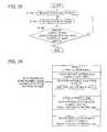
- FIG. 31 ( a ), 31 ( b ), and 31 ( c )are diagrams showing node series information, road additional information, and necessary time information according to Eighth Embodiment,
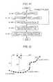
- FIG. 32is a block diagram showing a constitution of a position information transmitting/receiving apparatus according to Tenth Embodiment,
- FIGS. 33 ( a ), 33 ( b ), and 33 ( c )illustrate views for explaining compression and decoding of shape data according to Tenth Embodiment
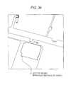
- FIG. 34is a view showing facility shape vectors in a digital map
- FIG. 35is a diagram showing vectors representing a prefectural boundary shape, contour lines, and a lake or marsh shape in a digital map
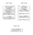
- FIG. 36is a diagram showing node series information of a house shape according to Eleventh Embodiment.
- FIG. 37is a diagram showing node series information of a water area shape according to Eleventh Embodiment.
- FIG. 38is a diagram showing node series information of an administrative boundary shape according to Eleventh Embodiment.
- FIG. 39is a diagram showing node series information of a contour line shape according to Eleventh Embodiment.
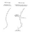
- FIG. 40is a view for explaining a method of expressing a position outside of a road according to Twelfth Embodiment
- FIG. 41is a flowchart showing a procedure of reproducing a position according to Twelfth Embodiment
- FIG. 42is a view for explaining other method for expressing a position outside of a road according to Twelfth Embodiment,
- FIG. 43is a flowchart showing other procedure of reproducing a position according to Twelfth Embodiment.
- FIG. 44is a view for explaining an example of map matching
- FIG. 45is a view for explaining road shape data and relative position information
- FIG. 46is a view for explaining a intercept azimuth
- FIG. 47is a view for explaining a method of restoring data in a section approximated by a straight line according to Tenth Embodiment,
- FIG. 48is a view for explaining a method of restoring data at a section approximated by a function according to Tenth Embodiment
- FIG. 49is a view for explaining a method of expressing coordinates of a node by a distance and an argument between the node and a preceding node,
- FIGS. 50 ( a ), 50 ( b ), and 50 ( c )are diagrams showing node series information representing coordinates of a node by a distance and an argument between the node and a preceding node,
- FIGS. 51 ( a ) and 51 ( b )are views schematically showing shape data representing coordinates of a node by a distance and an argument between the node and a preceding node,
- FIG. 52is a view schematically showing a map matching processing when coordinates of a node are represented by a distance and an argument between the node and a preceding node, and
- FIG. 53is a view showing a way of calculating a successive candidate point in the map matching processing when the coordinates of the node are represented by the distance and the argument between the node and the preceding node.
- the numerals in the drawingsare 10 , 20 position information transmitting/receiving apparatus, 11 , 22 position information receiving portion, 12 node series restoring portion, 13 map matching portion, 14 digital map data base, 15 digital map displaying portion, 16 event information inputting portion, 17 position information Converting portion, and 18 , 21 position information transmitting portion.
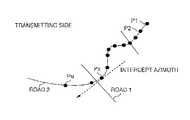
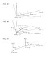
- FIG. 1An explanation will be given of an example of a case of transmitting longitude data and latitude data of respective spots indicated by black circles as shape data in order to transmit a road shape from P 1 to P N of a road 2 shown in FIG. 1 .
- the black circlesrepresent nodes and interpolation points of nodes on the roads included in a digital map database.
- a nodeis set in correspondence with a crossroads, an inlet or an outlet of a tunnel, an inlet or an outlet of a bridge, a boundary of administrative sections or the like and is attached with a node number.
- An interpolation pointis a point set for reproducing a road shape between nodes.
- a node and an interpolation pointare inclusively referred to as nodes so far as not particularly specified otherwise.
- longitude data and latitude data of respective nodesare stored in digital map databases on a transmitting side and a receiving side, as mentioned above, data respectively include error.
- the transmitting sidetransmits shape data indicating road shape by including longitude and latitude data of P 1 , P 2 , . . . , P N , in order to reduce a data amount, longitude and latitude data of P 1 is displayed by absolute coordinate values (longitude, latitude) and longitude and latitude data of P 2 , . . . , P N are displayed by relative coordinate values indicating differences from the longitude and latitude data of P 1 , or differences from longitude and latitude data of a preceding node.
- intercept azimuth information included in the shape datais information of azimuth of an intercept at a position of the respective node, that is, azimuth of a tangential line in contact with a road curve at node p x .
- the intercept azimuth at the node positionis displayed in a range of 0 degree through 360 degrees in the clockwise direction by defining an absolute azimuth of due north as 0 degree.
- the intercept azimuth of the node P xcan be calculated as follows when a contiguous node disposed on the upstream side of the node p x is defined as p x ⁇ 1 and a contiguous node disposed on the downstream side of the node p x is defined as P x+1 , by averaging an azimuth ⁇ x ⁇ 1 of a straight line connecting node p x ⁇ 1 and node p x and an azimuth ⁇ x of a straight line connecting node p x and p x+1 . ( ⁇ x ⁇ 1 + ⁇ x )/2
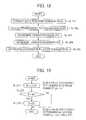
- FIG. 2shows a procedure of calculating an intercept azimuth of respective node on a transmitting side as follows.
- Step 91Sample respective node position from map data
- Step 92Sample intercept azimuth of respective node position.
- Intercept azimuths of respective nodes sampled in this wayare summarized as node series information representing shape data along with longitude and latitude data of respective nodes as shown by FIG. 3 .
- the node series informationis aligned with kinds of vector data represented by node series (in this case, “road”), a total number of nodes (N pieces) and longitude and latitude data and intercept azimuth data with regard to respective nodes starting from node No. P 1 .
- longitude and latitude data and intercept azimuth data of node No. P 1are displayed by absolute coordinates and an absolute azimuth
- longitude and latitude data and intercept azimuth data of from node No. P 2 through node No. P Nare displayed by relative coordinates and relative azimuths in order to reduce a data amount.
- the node series informationis converted into a transmission format along with relative position data representing positions of events in the road section represented by the node series information and is transmitted.
- the receiving side receiving the node series information and relative position dataexecutes map matching and specifies the road section represented by the node series information.
- FIG. 5shows a procedure in map matching.
- Step 121Sample a position on the road proximate to the longitude and latitude data of node No. P x as a matching candidate in an order of proximity,
- Step 122Calculate a difference between a section azimuth of the candidate position and a section azimuth of P x .
- the matching candidateis constituted to thereby constitute an object of map matching explained in reference to FIG. 44 .
- the operationreturns to step 121 , samples a next proximate one as a matching candidate and executes the procedure of step 122 .
- spot P x on road 2is liable to be erroneously matched to road 1 constituting the most proximate road, as shown by FIG. 4 , on the receiving side, in matching, by comparing intercept azimuths of matching candidate point 1 on road 1 most proximate to spot P x and spot P x , matching candidate point 1 can be excluded from the candidate and matching candidate 2 on road 2 next proximate to spot P x can remain as the candidate.
- the method of transmitting position information of the embodimentby including the intercept azimuth information to the position information, matching accuracy on the receiving side is promoted and the candidate can be narrowed down in a short period of time. Therefore, on the receiving side, the transmitted position on the digital map can accurately and swiftly be recognized.
- coordinate pointsmay be resampled at constant intervals on the road shape and the shape data indicating the road shape may include coordinate data of the coordinate points.
- Second Embodimentan explanation will be given of a method of transmitting position information for transmitting shape data by adding data of height.
- FIG. 6schematically shows vector data series representing a road in the case of representing digital map data in three dimensions of longitude, latitude and height.
- the transmitting sidetransmits node series information of shape data by including X direction coordinate (longitude), Y direction coordinate (latitude) and Z direction coordinate (altitude) of respective node as shown by FIG. 7 .
- candidate pointscan be narrowed down by referring to Z direction coordinate of matching candidate points selected based on distances on X-Y plane and transmitted positions on the digital map can accurately and swiftly be recognized.
- Z direction coordinate of respective nodeis represented by altitude
- the Z direction coordinatemay be displayed by a height from the surface of the ground.
- the Z direction coordinate of respective nodemay be displayed by a slope between the node and a preceding node.
- shapes from P 1 through P m1 and P m1 through P m2are approximated by a basic function F (h, r 1 , r 2 ) such as a cosine curve shown in FIG. 9 ( c ).
- Notations h, r 1 and r 2designate parameters of the function.
- P 1 through P m2can be represented by coordinates data of P 1 , P m1 and P m2 , a function approximating an interval of P 1 through P m1 indicated by F (a, b, c) and parameters thereof and a function approximating an interval of P m1 through P m2 indicated by F (d, e, f) and parameters thereof to thereby enable to reduce the data amount.
- FIG. 10shows node series information in this case.
- the shape represented by F (a, b, c) and F (d, e, f)may not coincide accurately with the shapes from P 1 through P m1 and P m1 through P m2 of FIG. 9 ( a ) but may be approximated thereto to a degree of not causing erroneous matching on the receiving side.
- the transmitted data amountcan considerably be reduced and efficient formation of data transmission can be achieved.
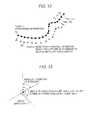
- an express way or a toll roadis expressed by a road separating up and down ways in a number of digital maps and is referred to as double-streaked line.
- road shape data of one road(road 2 ) utilizes road shape data of other road (road 1 ) to thereby enable to compress a data amount.
- node spots P 1 ′, P 2 ′, . . . , P n ′ of road 2can be approximated as spots produced by moving road spots P 1 , P 2 , . . . , P n in road 1 to a right side (or left side) of road 1 by a constant offset distance (L).
- a direction of offsetis a direction orthogonal to a intercept direction of each of the node spots P 1 , P 2 , . . . , P n of road 1 .
- node series informationthere are described a shape vector series identifying number constituting an identifying number of shape data at top thereof and a reference vector series number representing shape data to be referred.
- the reference vector series numberbecomes “none” and there are described longitude and latitude data and intercept azimuth data for respective nodes similar to the first embodiment (FIG. 3 ).
- node series information of road 2 referring to the shape data of road 1describes a shape vector series identifying number of road 2 , a reference vector series number representing the shape data of road 1 of the reference, an offset distance and an offset direction (right or left of node series constituting master).
- the system of the embodimentis also applicable by constituting an object by roads in a lattice shape in which the number of roads run in parallel.
- original map shapeis more ore less deformed to a degree of not causing erroneous matching on the receiving side and transmitted.
- FIG. 17schematically shows deformation of shape data in this case.
- P xan original position provided to map data
- the positionis modified to a position of P x ′.
- a distance (transition value B) from P x to P x ′is set based on a distance L from spot P x to a contiguous road, further, an azimuth (transition azimuth ⁇ ) P x to P x ′ is determined by a random number.
- FIG. 18shows a procedure of calculating P x ′.
- Step 261Sample node position P x from map data
- Step 262Calculate distance L to contiguous road
- Step 263Determine transition value B.
- Step 272Compare B calculated at the step 271 with ⁇ 2 .
- step 272when B ⁇ 2 , the value calculated at step 271 is determined as B.
- notation Rdesignates a random number is generating function and is a uniform random number of 0 through 1.
- notation ⁇represents an absolute azimuth of 0 degree through 360 degrees in the clockwise direction by defining an absolute azimuth of due north by 0 degree.
- Step 265Calculate coordinates P x ′ after transition by using the determined transition value B and transition azimuth ⁇ .
- the map datacan be deformed to a degree of not causing erroneous matching on the receiving side.
- a node P 4 of a crossroads in the midst of a node seriesis defined as a reference point and the position of traffic accident is displayed by a relative distance from P 4 .
- traffic jam caused in the road sectionis displayed by a relative distance from a node P x of a T-road as a reference point.
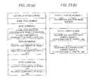
- Relative position information displayed by using the reference point defined in the road section in this wayis transmitted to the receiving side by data shown in FIGS. 21 ( a ), 21 ( b ), and 21 ( c ).
- FIG. 21 ( a )is node series information specifying the road section.
- FIG. 21 ( b )is road additional information proposed by Japanese Patent Application No. 242166/1999 displaying a node number linked to the node series information, a number of connection links of crossroads and connection link angles of the respective connection links with respect to crossroads nodes included in the road section for respective crossroads nodes along with a road kind code, a road number and a toll road code of the road constituting an object.
- FIG. 21 ( c )shows event information for displaying a relative position in the road section and event content of event occurring at the position and the relative position is displayed by a relative distance from a reference point indicated clearly.
- the receiving sidecan precisely grasp a position at which an event occurs.
- FIG. 23 ( a )in the node series information, only a code number and coordinate data are described, and as shown by FIG. 23 ( b ), as event information, event content and a node number at which event occurs are described.
- the event occurring positioncan be reproduced with high accuracy.
- FIG. 24schematically shows a state in which an event A (traffic stop) influencing a vehicle running in a direction of a vehicle advancing direction 1 on a road and an event B (traffic lain regulation) influencing a vehicle running in a direction of a vehicle advancing direction 2 , occur.
- event Atraffic stop
- event Btraffic lain regulation
- position information on the roadis transmitted to the receiving side by data shown in FIGS. 25 ( a ), 25 ( b ), and 25 ( c ).
- FIG. 25 ( a )shows node series information specifying a road section.
- the node series informationthere is prescribed a definition of direction in which a forward direction with respect to an order of aligning node series is defined as 2 and a rearward direction with respect to the order of aligning the node series is defined as 1.
- FIG. 25 ( b )is road addition information similar to that in Sixth Embodiment (FIGS. 21 ( a ), 21 ( b ), and 21 ( c )).
- FIG. 25 ( c )shows event information displaying an event content, a relative distance from a reference point as well as a vehicle advancing direction influenced by the event by a direction identifying flag indicating the definition of direction with regard to respective event. That is, a vehicle running in a direction of a vehicle advancing direction 1 is influenced by an event A and therefore, 1 defining a rearward direction is displayed at the direction identifying flag and a vehicle running in a direction of a vehicle advancing direction 2 is influenced by an event B and therefore, the direction identifying flag is displayed with 2 defining a forward direction.
- the road sectioncan be specified by map matching with regard to an alignment in one direction of nodes P 1 , P 2 , . . . , P n displayed by the node series information and an event occurring position in the road section including the vehicle advancing direction can be specified based on relative information and the direction identifying flag described in the event information. Therefore, events in two directions can be expressed by map data in one direction and a data amount can be compressed.
- step 341Receive node series information
- step 342Execute map matching and sample road spot of matching candidate.
- Step 343Designate one way traffic of the candidate is spot on map data and compare the designated one way traffic with one way traffic direction information of node series. When these coincide with each other, the matching candidate is made to remain and when these do not coincide with each other, the candidate is excluded from the matching candidate, the operation returns step 342 and samples a successive matching candidate.
- two reference points (P 4 , P x )are set and travel time between the reference points is transmitted by data shown in FIGS. 31 ( a ), 31 ( b ), and 31 ( c ).
- FIG. 31 ( a )shows node series information for specifying a traffic section including the two reference points.
- FIG. 31 ( b )shows road additional information similar to that of FIG. 21 ( b ) explained in Sixth Embodiment
- FIG. 31 ( c )shows necessary time information displaying travel time, describing a start end side node number (P 4 ), a finish end side road number (P x ) and travel time therebetween.
- the road sectioncan be specified by map matching and the travel time between the reference points can be recognized from the necessary time information.
- FIG. 32shows a position information transmitting/receiving apparatus 10 receiving and reproducing position information, further, generating and transmitting position information informing event occurrence.
- the apparatus 10is provided with a position information receiving portion 11 for receiving position information transmitted from a position information transmitting portion 21 of other apparatus 20 , a node series restoring portion 12 for converting shape data included in the position information into a vector data series which is easy to execute map matching, a digital map data base 14 for accumulating digital map data, a map matching portion 13 for specifying a road section represented by the position information by executing map matching, a digital map displaying portion 15 for displaying the road section represented by the position information and an event position, an event inputting portion 16 for inputting information of an event which occurs, a position information converting portion 17 for generating position information for transmitting an even occurring position and a position information transmitting portion 18 for transmitting the generated position information to a position information receiving portion 22 of the other apparatus 20 .
- the position information receiving portion 11receives the position information and the node series restoring portion 12 converts shape data subjected to data compression by approximation by a function included therein or thinning into a shape vector data series at equal intervals
- FIG. 33 ( a )shows a shape vector data series before compression
- FIG. 33 ( b )shows data compressed by thinning and function approximation
- the node series restoring portion 12restores a shape data series at equal intervals from data of FIG. 33 ( b ) as shown by FIG. 33 ( c ).
- the map matching portion 13detects a road section matched to the restored shape vector data series from map data accumulated in the digital tap data base 14 , further, specifies an event occurring position of the road section and displays these to the digital map displaying portion 15 .
- the position information converting portion 17when even information is inputted from the event information inputting portion 16 , the position information converting portion 17 generates position is information for designating the road section including the event occurring position and the even occurring position in the road section and the position information is transmitted from the position information transmitting portion 18 .
- nodes included in the road sectionnodes having a low degree of contributing to map matching are thinned and for such purpose, with regard to an azimuth from a contiguous node to a corresponding node, when a change in an azimuth from the corresponding node to a successive node is equal to or smaller than predetermined angle and a distance from the contiguous node to the corresponding node is less than a predetermined distance, the corresponding node is thinned.
- the node series restoring portion 12restores data at equal intervals as follows. In this case, data is restored such that the respective interval does not shift from a constant distance A (meter) by ⁇ b (meter) or more.
- an interval between P n ⁇ 1 (X n ⁇ 1 , Y n ⁇ 1 ) and P n (X n , Y n )is regarded as a straight line and points are generated at an interval of A meter. Such a pattern is shown in FIG. 47 .
- P n1F(P n1 ′)
- P n1F(P n1 ′)
- the compressed datais converted into a coordinate series at equal intervals. Therefore, matching processing of the map matching portion 13 is facilitated.
- the processing of the node series restoring portion 12may be realized by software or may be realized by hardware formed by IC.
- a data series at equal intervalsis restored from a data series subjected to data compression and therefore, the matching processing is facilitated and accuracy of map matching can be promoted.
- Digital map datainclude a vector series (V) representing a shape of a facility as shown by FIG. 34 , a vector series (X) representing a shape of a prefectural boundary, a vector series (Y) representing a shape of a lake or marsh and a vector series (W) representing a shape of contour lines as shown by FIG. 35 .
- Vvector series
- Xa shape of a prefectural boundary
- Ya shape of a lake or marsh
- Wvector series representing a shape of contour lines as shown by FIG. 35 .
- FIG. 36shows shape data representing a shape of a house.
- a shape vector kindis described as house and an identification code of a building or a general house each described as detailed information. Successively, a node total number and respective node coordinates representing a shape of a house are described and an event occurring position is prescribed by a relative distance from a top node position.
- FIG. 37shows shape data representing a shape of a water area
- a shape vector kindis described as water area and as detailed information, an identification code of a face expressing water area such as lake or a line expressing water area such as river is described. The other is the same as that in the case of a shape of a house.
- FIG. 38shows shape data representing a shape of an administrative boundary.
- a shape vector kindis described as administrative boundary and as detailed information, an identification code of a prefectural boundary, a city boundary, or town boundary is described.
- FIG. 39shows shape data representing a shape of a contour line.
- a shape vector kindis described as contour line and as detailed information, an identification code of contour line meters above sea level is described.
- the transmitting sidesets three reference points (event point 1 , event point 2 , event point 3 ) and transmits to the receiving side, shape data of a road section (map matching data 1 ) including the event point 1 , data of a distance r 1 and an azimuth ⁇ 1 from the event point 1 to the reproduced position, shape data of a road section (map matching data 2 ) including the event point 2 , data of a distance r 2 and an azimuth ⁇ 2 from the event point 2 to the reproduced position, as well as, shape data of a road section (map matching data 3 ) including the event point 3 and data of a distance r 3 and an azimuth ⁇ 3 from the event point 3 to the reproduced position.
- the reproduced positionis reproduced by a procedure shown in FIG. 41 .
- Step 481Execute map matching by using map matching data 1 ,
- Step 482Specify event point 1 on road.
- Step 483Calculate spot P 1 disposed at distance r 1 , azimuth ⁇ 1 from event point 1 .
- the event point 2is specified from the map matching data 2 , a spot P 2 disposed at the distance r 2 and the azimuth ⁇ 2 from the event point 2 is calculated, the event point 3 is specified from the map matching data 3 and the spot P 3 disposed at the distance and r 3 and the azimuth ⁇ 3 from the event point 3 is calculated.
- Step 484Calculate gravitational center of point P 1 , P 2 , P 3 ,
- Step 489Constitute reproduced position by position of gravitational center.
- the three event pointsmay be set on a single road (map matching data).
- the reproduced position viewed from the respective event pointcan be expressed by using reference data ( ⁇ x n , ⁇ y n ) of an x coordinate and a y coordinate.
- the reproduced positionis reproduced by a procedure shown in FIG. 43 .
- Step 501Execute map matching by using map matching data
- Step 502Specify event point 1 on road
- Step 503Calculate spot P 1 at ⁇ x 1 , ⁇ y 1 , from even point 1 .
- step 502 and step 503are repeated and the spot P 2 at ⁇ x 2 , ⁇ y 2 , from the event point 2 and the spot P 3 at ⁇ x 3 , ⁇ y 3 , from the event point 3 are calculated.
- Step 504Calculate gravitational center of point P 1 , P 2 , P 3 ,
- Step 505Constitute reproduced position by position of gravitational center.
- map matching dataother than that of road, there can also be utilized vector series representing a shape of a facility explained in Third Embodiment, vector series representing a shape of a prefectural boundary, vector series representing a shape of a lake or marsh, or a vector series representing a shape of a contour line.
- the reference pointscan be specified with high accuracy on a digital map of its own and therefore, by the relative information from the reference points, the target position can be calculated statistically.
- coordinates data of respective nodes included in shape dataare represented by absolute values or relative values of longitude and latitude data
- the coordinates data of the respective nodesmay be represented by using other parameters.
- nodes P j ⁇ 1 , P j and P j+1represented by xy coordinates as (x j ⁇ 1 , y j ⁇ 1 ), (x j , y j ) and (x j+1 , y j+1 )
- a distance of a straight line P j ⁇ 1 ⁇ P jis designated by notation L j
- an absolute azimuth (angle in clockwise direction with north as a reference) of the straight line P j ⁇ 1 ⁇ P jis designated by notation ⁇ j ⁇ 1
- a distance of a straight line P j ⁇ P j+1is designated by notation L j+1
- an absolute azimuth of the straight line P ⁇ P j+1is designated by notation ⁇ j
- the node P jcan be specified by using the distance L j from the preceding node P j ⁇ 1 and the absolute azimuth ⁇ j ⁇ 1 .
- L j and ⁇ j ⁇ 1can be calculated from xy coordinate values of P j ⁇ 1 and P j by the following equations.
- the node P j+1can similarly be specified by using the distance L j+1 from the preceding node P j and the absolute azimuth ⁇ j .
- the node P j+1can also be specified by using the distance L j+1 and an argument from the preceding node P j , that is, an azimuth difference ⁇ j between the absolute azimuth ⁇ j of P j ⁇ P j+1 and the absolute azimuth ⁇ j ⁇ 1 of P j ⁇ 1 ⁇ P j .
- the argument ⁇ jcan be calculated from respective coordinate values of P j ⁇ 1 , P j and P j+1 by the following equation.
- FIGS. 50 ( a ), 50 ( b ), and 50 ( c )exemplify transmitted data representing node series information included in shape data by using a distance and an argument from a preceding node.
- the transmission data of FIG. 50 ( a )includes data of interpolation points # 1 through #a between a node p 1 and a node P 2 and the data of the interpolation points are constituted by data of distances and arguments from preceding nodes or preceding interpolation points.
- the node p 1includes data of absolute coordinates (longitude, latitude) representing a position and an absolute azimuth in a intercept direction (absolute azimuth of a straight line connecting p 1 and the interpolation point # 1 ).
- data of the interpolation point # 1includes an argument data representing an argument difference between an absolute azimuth of a straight line extending from the interpolation point # 1 to the interpolation point # 2 and the absolute azimuth in the intercept direction
- distance data from p 1 to the interpolation point # 1 and data of the interpolation point # 2is similarly constituted by using an argument data of an absolute azimuth of a straight line extended from the interpolation point # 2 to the interpolation point # 3 and the absolute azimuth of the straight line extended from the interpolation point # 1 to the interpolation point # 2 and distance data from the interpolation point # 1 to the interpolation point # 2 .
- data of respective nodes excluding the node P 1 at the start endare constituted by distances and arguments from preceding nodes.
- FIGS. 51 ( a ) and 51 ( b )schematically show a shape ( a ) of an object road section of original map data and a coordinate series (b) representing the shape by distances and arguments from preceding nodes. Further, as shown by FIGS. 51 ( a ) and 51 ( b ), the nodes capable of reproducing the shape of the object road section by a smaller number from the original map data of the object road section may be resampled and the resampled nodes may be expressed by the distances and arguments from the preceding nodes.
- FIG. 52schematically shows a map matching processing on the receiving side receiving the transmitted data.
- map matchingon a digital map of its own, firstly, candidate points in correspondence with a start end node P 1 of shape data are set. For that purpose, n pieces of candidates are set on n pieces of contiguous nodes substantially within 200 m from a latitude and longitude data position of the start end node p 1 .
- the candidate point P j,1is moved to the candidate point P j+1,1 .
- Such a processingis repeated for all of the candidate points, further, a similar processing is executed for all of nodes included in the shape data.
- a candidate having the least operation value ⁇ iis selected as the object load.
- map matching processingby using “distance L 1 from the preceding node” included in shape data, a successive candidate point can easily be calculated, further, the evaluation value can be calculated by directly using “relative azimuth” included in the shape data. Therefore, processing load of the map matching on the receiving side is alleviated.
- the present inventionis based on Japanese Patent Applications No. 2000-375320 filed on Dec. 8, 2000, and No. 2001-220062 filed on Jul. 19, 2001, which are incorporated herein by references.
- positions of the digital mapcan efficiently and accurately be transmitted.
- a transmitting method for approximating a shape data series by a function or displaying shape data of a double-streaked line by an offset distancea data amount can be reduced and a data transmission efficiency can be promoted.
- a transmitting method for displaying a relative distance up to an event position by setting a reference point at a crossroads or the like in a road section, or prescribing an event position by a node numberaccuracy of specifying the event position on the receiving side can be promoted.
- a direction of advancing a vehicle influenced by an eventcan be specified.
- a matching efficiency on the receiving sidecan be promoted.
- travel timecan be transmitted, further, data can be transmitted in the form of not infringing copyright of map data.
- the inventionis applicable also to transmission of vector data other than that of a road, further, a position outside of a road on a digital map can also be transmitted.
Landscapes
- Engineering & Computer Science (AREA)
- Radar, Positioning & Navigation (AREA)
- Remote Sensing (AREA)
- Physics & Mathematics (AREA)
- General Physics & Mathematics (AREA)
- Theoretical Computer Science (AREA)
- Mathematical Physics (AREA)
- Automation & Control Theory (AREA)
- Business, Economics & Management (AREA)
- Educational Administration (AREA)
- Educational Technology (AREA)
- Navigation (AREA)
- Traffic Control Systems (AREA)
- Instructional Devices (AREA)
- Position Fixing By Use Of Radio Waves (AREA)
Abstract
Description
(x0, y0)(x1y1)(xk, yk).
as shown by
(θx−1+θx)/2
θ=R×360 (degree)
Xnm=Xn−1+m×(Asin θ)
Xnm=Yn−1+m×(Acos θ)
Xn1′=Xn−1+1×(L′ sin θ)
Xn1′=Yn−1+1×(L′ cos θ)
Xn1=Xn1′+{F(1×L′)sin(θ−90)}
Yn1=Yn1′+{F(1×L′)cos(θ−90)}
Lj=√{square root over ( )}{(xj−xj−1)2+(yj−yj−1)2}
ωj−1=tan−1{(xj−xj−1)/(yj−yj−1)}
Θj=ωj−ωj−1
=tan−1{(xj−1−xj)/(yj+1−yj)}
−tan−1{(xj−xj−1)/(yj−yj−1)}
εj,1=α×D1+Σ(β×|Δθj,1|)
(Σ designates addition of J=1 to j)
- α: predetermined coefficient
- β: predetermined coefficient.
Claims (41)
Priority Applications (2)
| Application Number | Priority Date | Filing Date | Title |
|---|---|---|---|
| US11/133,591US8086401B2 (en) | 2000-12-08 | 2005-05-20 | Method for transmitting information on position on digital map and device used for the same |
| US13/303,522US8655580B2 (en) | 2000-12-08 | 2011-11-23 | Method for transmitting information on position on digital map and device used for the same |
Applications Claiming Priority (5)
| Application Number | Priority Date | Filing Date | Title |
|---|---|---|---|
| JP2000375320 | 2000-12-08 | ||
| JP2000375320 | 2000-12-08 | ||
| JP2001220062AJP5041638B2 (en) | 2000-12-08 | 2001-07-19 | Method for transmitting location information of digital map and device used therefor |
| JP2001220062 | 2001-07-19 | ||
| PCT/JP2001/010748WO2002046697A1 (en) | 2000-12-08 | 2001-12-07 | Method for transmitting information on poisition on digital map and device used for the same |
Related Parent Applications (1)
| Application Number | Title | Priority Date | Filing Date |
|---|---|---|---|
| PCT/JP2001/010748A-371-Of-InternationalWO2002046697A1 (en) | 2000-12-08 | 2001-12-07 | Method for transmitting information on poisition on digital map and device used for the same |
Related Child Applications (1)
| Application Number | Title | Priority Date | Filing Date |
|---|---|---|---|
| US11/133,591DivisionUS8086401B2 (en) | 2000-12-08 | 2005-05-20 | Method for transmitting information on position on digital map and device used for the same |
Publications (2)
| Publication Number | Publication Date |
|---|---|
| US20030078720A1 US20030078720A1 (en) | 2003-04-24 |
| US6931319B2true US6931319B2 (en) | 2005-08-16 |
Family
ID=26605563
Family Applications (3)
| Application Number | Title | Priority Date | Filing Date |
|---|---|---|---|
| US10/169,644Expired - LifetimeUS6931319B2 (en) | 2000-12-08 | 2001-12-07 | Method for transmitting information on position on digital map and device used for the same |
| US11/133,591Expired - Fee RelatedUS8086401B2 (en) | 2000-12-08 | 2005-05-20 | Method for transmitting information on position on digital map and device used for the same |
| US13/303,522Expired - Fee RelatedUS8655580B2 (en) | 2000-12-08 | 2011-11-23 | Method for transmitting information on position on digital map and device used for the same |
Family Applications After (2)
| Application Number | Title | Priority Date | Filing Date |
|---|---|---|---|
| US11/133,591Expired - Fee RelatedUS8086401B2 (en) | 2000-12-08 | 2005-05-20 | Method for transmitting information on position on digital map and device used for the same |
| US13/303,522Expired - Fee RelatedUS8655580B2 (en) | 2000-12-08 | 2011-11-23 | Method for transmitting information on position on digital map and device used for the same |
Country Status (11)
| Country | Link |
|---|---|
| US (3) | US6931319B2 (en) |
| EP (8) | EP2287566B1 (en) |
| JP (1) | JP5041638B2 (en) |
| KR (1) | KR20030070051A (en) |
| CN (2) | CN101551251B (en) |
| AU (1) | AU2002222591A1 (en) |
| CA (1) | CA2428347C (en) |
| DK (1) | DK2287566T3 (en) |
| ES (2) | ES2411131T3 (en) |
| MY (2) | MY154963A (en) |
| WO (1) | WO2002046697A1 (en) |
Cited By (21)
| Publication number | Priority date | Publication date | Assignee | Title |
|---|---|---|---|---|
| US20040234475A1 (en)* | 2001-06-22 | 2004-11-25 | Helene Lannibois-Drean | Oil-in-oil emulsions comprising a silicone, dispersions and use of said emulsions |
| US20050058155A1 (en)* | 2003-08-26 | 2005-03-17 | Mitsubishi Denki Kabushiki Kaisha | Data structure of map data, map data storage medium, map data updating method and map data processing apparatus |
| US20050216189A1 (en)* | 2000-12-08 | 2005-09-29 | Matsushita Electric Industrial Co., Ltd. | Method for transmitting information on position on digital map and device used for the same |
| US20060155463A1 (en)* | 2003-06-11 | 2006-07-13 | Matsushita Electric Industrial Co., Ltd. | Digital map position information compressing method and device |
| US20060276961A1 (en)* | 2005-06-01 | 2006-12-07 | Kwon Pil Su | Navigation system with function of one-touch map matching correction and method thereof |
| US20070124063A1 (en)* | 2004-05-06 | 2007-05-31 | Tsuyoshi Kindo | Vehicle-mounted information processing apparatus |
| US20070126605A1 (en)* | 2003-08-16 | 2007-06-07 | Daimlerchrysler Ag | Method for updating a digital map |
| DE102006004130A1 (en)* | 2006-01-27 | 2007-08-09 | Audi Ag | Method for determining a future course of the road by communicating between motor vehicles |
| US20090299630A1 (en)* | 2008-05-30 | 2009-12-03 | Navteq North America, Llc | Data mining in a digital map database to identify insufficient superelevation along roads and enabling precautionary actions in a vehicle |
| US20090299615A1 (en)* | 2008-05-30 | 2009-12-03 | Navteq North America, Llc | Data mining in a digital map database to identify insufficient merge lanes along roads and enabling precautionary actions in a vehicle |
| US20090299625A1 (en)* | 2008-05-30 | 2009-12-03 | Navteq North America, Llc | Data mining in a digital map database to identify blind intersections along roads and enabling precautionary actions in a vehicle |
| US20090299616A1 (en)* | 2008-05-30 | 2009-12-03 | Navteq North America, Llc | Data mining in a digital map database to identify intersections located over hills and enabling precautionary actions in a vehicle |
| US20090299626A1 (en)* | 2008-05-30 | 2009-12-03 | Navteq North America, Llc | Data mining in a digital map database to identify unusually narrow lanes or roads and enabling precautionary actions in a vehicle |
| US20090299624A1 (en)* | 2008-05-30 | 2009-12-03 | Navteq North America, Llc | Data mining in a digital map database to identify speed changes on upcoming curves along roads and enabling precautionary actions in a vehicle |
| US20090300067A1 (en)* | 2008-05-30 | 2009-12-03 | Navteq North America, Llc | Data mining in a digital map database to identify decreasing radius of curvature along roads and enabling precautionary actions in a vehicle |
| US20090299622A1 (en)* | 2008-05-30 | 2009-12-03 | Navteq North America, Llc | Data mining to identify locations of potentially hazardous conditions for vehicle operation and use thereof |
| US8195385B1 (en)* | 2002-10-30 | 2012-06-05 | Harrison Jr John H | Navigation control system |
| US20120202516A1 (en)* | 2011-02-08 | 2012-08-09 | Pantech Co., Ltd. | Apparatus and method for providing location-based data |
| US8531318B2 (en) | 2008-05-30 | 2013-09-10 | Navteq B.V. | Data mining in a digital map database to identify intersections located at hill bottoms and enabling precautionary actions in a vehicle |
| US8718932B1 (en)* | 2011-06-01 | 2014-05-06 | Google Inc. | Snapping GPS tracks to road segments |
| US9157749B2 (en) | 2011-04-11 | 2015-10-13 | Clarion Co., Ltd. | Position calculation method and position calculation apparatus |
Families Citing this family (56)
| Publication number | Priority date | Publication date | Assignee | Title |
|---|---|---|---|---|
| CN100383834C (en)* | 2002-08-28 | 2008-04-23 | 谢开章 | Designation method of city address and designated city map and transit stop board |
| JP2004264326A (en)* | 2003-01-22 | 2004-09-24 | Matsushita Electric Ind Co Ltd | Shape information encoding method and apparatus, shape information decoding method and apparatus, and program |
| JP2004280521A (en)* | 2003-03-17 | 2004-10-07 | Matsushita Electric Ind Co Ltd | Transmission trajectory transmission method and apparatus in probe car system |
| AT500123B1 (en)* | 2003-08-28 | 2007-01-15 | Oesterreichisches Forschungs U | METHOD AND ARRANGEMENT FOR DETERMINING THE ROUTES OF TRANSPORT PARTICIPANTS |
| JP2005121518A (en)* | 2003-10-17 | 2005-05-12 | Matsushita Electric Ind Co Ltd | Route information transmission method and apparatus |
| JP2005321370A (en) | 2004-04-05 | 2005-11-17 | Sony Corp | Navigation system, data processing method and computer program |
| JP4506862B2 (en)* | 2004-04-05 | 2010-07-21 | ソニー株式会社 | Navigation device, data processing method, and computer program |
| KR100628592B1 (en) | 2004-08-31 | 2006-09-26 | 한국과학기술원 | Semantic Maturity Location Information Storage System and Location Method for Location Based Services |
| WO2007007377A1 (en)* | 2005-07-07 | 2007-01-18 | Matsushita Electric Industrial Co., Ltd. | Positional information providing device and positional information utilizing terminal device |
| EP1901260A1 (en)* | 2005-07-07 | 2008-03-19 | Matsushita Electric Industrial Co., Ltd. | Map information correction device, map information correction method, program, information providing device using the program, and information acquisition device |
| JP4363371B2 (en)* | 2005-07-08 | 2009-11-11 | ブラザー工業株式会社 | Image forming data generation apparatus, method thereof, and program thereof |
| KR100782822B1 (en)* | 2005-10-18 | 2007-12-06 | 삼성전자주식회사 | Method and apparatus for providing location information, Method and apparatus for processing location information |
| ATE480752T1 (en)* | 2006-06-29 | 2010-09-15 | Navigon Ag | METHOD FOR THE AUTOMATIC, COMPUTER-AIDED DETERMINATION OF A ROUTE THAT CAN BE DRIVEN BY VEHICLES |
| JP4694443B2 (en)* | 2006-08-17 | 2011-06-08 | 本田技研工業株式会社 | NAVI SERVER, NAVI DEVICE, AND NAVI SYSTEM |
| US10605610B2 (en)* | 2007-04-09 | 2020-03-31 | Ian Cummings | Apparatus and methods for reducing data transmission in wireless client-server navigation systems |
| JP2010527062A (en)* | 2007-05-11 | 2010-08-05 | コーニンクレッカ フィリップス エレクトロニクス エヌ ヴィ | Method and apparatus for guiding a person to a destination |
| TW200900655A (en)* | 2007-06-21 | 2009-01-01 | Mitac Int Corp | Navigation device and method calibrated by map position-matching |
| JP4345897B2 (en)* | 2007-07-05 | 2009-10-14 | 本田技研工業株式会社 | Navigation device, navigation system |
| CN101082501B (en)* | 2007-07-13 | 2011-02-09 | 瑞典维方达软件技术有限公司 | Real time map-matching method and system based on relative coordinates positioning |
| US10083607B2 (en) | 2007-09-07 | 2018-09-25 | Green Driver, Inc. | Driver safety enhancement using intelligent traffic signals and GPS |
| US9852624B2 (en) | 2007-09-07 | 2017-12-26 | Connected Signals, Inc. | Network security system with application for driver safety system |
| US9043138B2 (en)* | 2007-09-07 | 2015-05-26 | Green Driver, Inc. | System and method for automated updating of map information |
| US20130131980A1 (en)* | 2007-09-07 | 2013-05-23 | On Time Systems, Inc. | Resolving gps ambiguity in electronic maps |
| US8260549B2 (en) | 2008-04-01 | 2012-09-04 | Decarta Inc. | Transmission of routes between client and server using route IDs |
| KR101049817B1 (en)* | 2008-10-06 | 2011-07-15 | 엔에이치엔(주) | Method and system for providing point of interest information to heterogeneous devices |
| KR200465479Y1 (en)* | 2008-11-26 | 2013-02-21 | 주식회사 메닉스 | A stylus pen |
| DE102010002093B4 (en)* | 2009-06-03 | 2024-03-14 | Continental Automotive Technologies GmbH | C2X communication with reduced data volume |
| US10198942B2 (en) | 2009-08-11 | 2019-02-05 | Connected Signals, Inc. | Traffic routing display system with multiple signal lookahead |
| CN101876549B (en)* | 2010-01-25 | 2013-04-10 | 青岛海信移动通信技术股份有限公司 | Method and mobile terminal for navigating by geographical positions |
| JP2011179883A (en)* | 2010-02-26 | 2011-09-15 | Fujitsu Ten Ltd | Navigation system, in-vehicle apparatus, program, and method of navigation |
| CN102252685A (en)* | 2010-05-21 | 2011-11-23 | 科菱航睿空间信息技术有限公司 | Navigation electronic map data processing method and storage method based on same |
| JP5511534B2 (en)* | 2010-06-16 | 2014-06-04 | 三菱電機株式会社 | Map information processing device |
| GB201018815D0 (en)* | 2010-11-08 | 2010-12-22 | Tomtom Int Bv | High-definition weather for improved routing and navigation systems |
| CN102542901B (en)* | 2010-12-17 | 2015-04-08 | 上海博泰悦臻电子设备制造有限公司 | Line segment vacuating device for electronic map and method thereof |
| EP2500887B1 (en)* | 2011-03-17 | 2020-09-09 | Harman Becker Automotive Systems GmbH | Description of a Road Segment Using ISO 17572-3 |
| EP2602591B1 (en)* | 2011-12-06 | 2016-04-20 | Telenav GmbH | Method for simplified storage of data representing shapes |
| CN103838240B (en)* | 2012-11-27 | 2018-02-27 | 联想(北京)有限公司 | Control method and electronic equipment |
| DE102012223780A1 (en)* | 2012-12-19 | 2014-06-26 | Bayerische Motoren Werke Aktiengesellschaft | Method and system for generating traffic information for at least one vehicle |
| DE102014221777A1 (en)* | 2014-10-27 | 2016-04-28 | Robert Bosch Gmbh | Method and device for operating a vehicle |
| US11002552B2 (en) | 2016-04-06 | 2021-05-11 | Mitsubishi Electric Corporation | Map data generation system and method for generating map data |
| CN107655487B (en)* | 2016-07-25 | 2020-05-08 | 高德软件有限公司 | Road section direction identification method and device |
| CN106128268B (en)* | 2016-08-24 | 2022-04-15 | 鞍钢集团矿业有限公司 | Simulation device and method for actual ore body excavation |
| CN106128275B (en)* | 2016-08-24 | 2022-04-15 | 鞍钢集团矿业有限公司 | Test device and method for simulating open-air transfer well mining rock collapse and pit bottom waterproof |
| JP6583322B2 (en) | 2017-03-17 | 2019-10-02 | カシオ計算機株式会社 | POSITION ESTIMATION DEVICE, POSITION ESTIMATION METHOD, AND PROGRAM |
| KR102612960B1 (en)* | 2018-01-23 | 2023-12-13 | 삼성전자주식회사 | Method for receiving a map and apparatus thereof |
| JP7190813B2 (en)* | 2018-01-31 | 2022-12-16 | 三菱電機株式会社 | MAP DATA GENERATION PROGRAM, COMPUTER-READABLE RECORDING MEDIUM AND MAP DATA GENERATION DEVICE |
| JP6633125B2 (en)* | 2018-04-26 | 2020-01-22 | 株式会社Vip | In-vehicle device, determination system, program, and determination method |
| DE102018208207A1 (en)* | 2018-05-24 | 2019-11-28 | Bayerische Motoren Werke Aktiengesellschaft | Control of a motor vehicle |
| DE102018005869A1 (en)* | 2018-07-25 | 2020-01-30 | Zf Active Safety Gmbh | System for creating an environmental model of a vehicle |
| JP2020101466A (en)* | 2018-12-21 | 2020-07-02 | 株式会社クボタ | Farm field shape generation system and farm field shape generation device |
| CN109947890A (en)* | 2019-03-27 | 2019-06-28 | 重庆卡佐科技有限公司 | The drafting cartoon implementing method and device of map real-time track |
| CN111556581B (en)* | 2020-04-21 | 2024-01-19 | 上海海事大学 | Terminal for eliminating hiding and exposing and medium access control method for implementing positioning |
| CN111881244B (en)* | 2020-07-30 | 2025-06-27 | 梅赛德斯-奔驰集团股份公司 | Method and apparatus for matching V2X technology with encrypted and/or deflected high-precision maps |
| CN112835080B (en)* | 2021-01-21 | 2024-03-19 | 成都路行通信息技术有限公司 | Track repairing method and device for vehicle in stationary state and electronic equipment |
| DE102021205517A1 (en)* | 2021-05-31 | 2022-12-01 | Robert Bosch Gesellschaft mit beschränkter Haftung | Method for determining an attribute on a digital map for a vehicle |
| CN115602041B (en)* | 2021-07-09 | 2024-04-09 | 华为技术有限公司 | Information generation method and device, information use method and device |
Citations (75)
| Publication number | Priority date | Publication date | Assignee | Title |
|---|---|---|---|---|
| US4807127A (en) | 1986-12-10 | 1989-02-21 | Sumitomo Electric Industries, Ltd. | Vehicle location detecting system |
| US4819175A (en) | 1986-09-25 | 1989-04-04 | Siemens Aktiengesellschaft | Navigation equipment for a moving vehicle |
| US4893246A (en) | 1986-12-15 | 1990-01-09 | Honda Giken Kogyo Kabushiki Kaisha | Apparatus for displaying travel path |
| US4924699A (en) | 1986-10-13 | 1990-05-15 | Hitachi, Ltd. | Position measuring method using a satellite |
| US4930888A (en) | 1987-11-07 | 1990-06-05 | Messerschmitt-Boelkow-Blohm Gesellschaft Mit Beschraenkter Haftung | Situation display system for attachment to a headgear |
| US4963864A (en) | 1987-08-07 | 1990-10-16 | Honda Giken Kogyo Kabushiki Kaisha | Apparatus for displaying travel path |
| US4963865A (en) | 1986-03-14 | 1990-10-16 | Honda Giken Kogyo Kabushiki Kaisha | Apparatus for displaying travel path |
| US4984168A (en) | 1987-06-06 | 1991-01-08 | Robert Bosch Gmbh | Method and apparatus for determining a route between a starting point and a destination |
| US5040122A (en) | 1987-05-06 | 1991-08-13 | Robert Bosch Gmbh | Method and system to determine the position of a land vehicle during movement over a predetermined path |
| US5046011A (en) | 1988-07-05 | 1991-09-03 | Mazda Motor Corporation | Apparatus for navigating vehicle |
| US5067082A (en) | 1988-08-11 | 1991-11-19 | Aisin Aw Co., Ltd. | Navigation apparatus |
| US5214757A (en) | 1990-08-07 | 1993-05-25 | Georesearch, Inc. | Interactive automated mapping system |
| US5307278A (en) | 1990-08-13 | 1994-04-26 | U.S. Philips Corporation | Method of determining the position of a vehicle, arrangement for determining the position of a vehicle, as well as a vehicle provided with such an arrangement |
| US5311195A (en) | 1991-08-30 | 1994-05-10 | Etak, Inc. | Combined relative and absolute positioning method and apparatus |
| US5406642A (en) | 1988-12-23 | 1995-04-11 | Nec Corporation | Image matching method using direction sensitivity and vector smoothing functions for correcting matches |
| US5442559A (en) | 1992-10-14 | 1995-08-15 | Pioneer Electronic Corporation | Navigation apparatus |
| EP0478438B1 (en) | 1990-09-28 | 1995-12-13 | Societe D'applications Generales D'electricite Et De Mecanique Sagem | Car navigation aid on-board receiver |
| US5488559A (en)* | 1993-08-02 | 1996-01-30 | Motorola, Inc. | Map-matching with competing sensory positions |
| US5581259A (en)* | 1994-11-03 | 1996-12-03 | Trimble Navigation Limited | Life for old maps |
| US5742923A (en) | 1992-10-20 | 1998-04-21 | Pioneer Electronic Corporation | Method of correcting distance error of navigation apparatus and navigation apparatus |
| WO1998027530A1 (en) | 1996-12-16 | 1998-06-25 | Mannesmann Ag | Process for transmitting route information concerning the recommended route of a vehicle in a road network between a traffic information centre and a terminal mounted in a vehicle, terminal and traffic information centre |
| WO1998045724A1 (en) | 1997-04-09 | 1998-10-15 | Robert Bosch Gmbh | Locating device for vehicles |
| EP0875877A2 (en) | 1997-05-02 | 1998-11-04 | Pioneer Electronic Corporation | Navigation system |
| US5839087A (en) | 1995-06-09 | 1998-11-17 | Zanavy Informatics Kk | Current position calculating system for a vehicle having a function for correcting a vehicle direction |
| WO1998054682A1 (en) | 1997-05-30 | 1998-12-03 | Booth David S | Generation and delivery of travel-related, location-sensitive information |
| US5862511A (en) | 1995-12-28 | 1999-01-19 | Magellan Dis, Inc. | Vehicle navigation system and method |
| JPH1151679A (en) | 1997-08-01 | 1999-02-26 | Fujitsu Ten Ltd | Navigation system |
| US5899954A (en) | 1995-04-21 | 1999-05-04 | Xanavi Informatics Corporation | Current position calculating system having a function for correcting a distance factor |
| WO1999024787A2 (en) | 1997-10-31 | 1999-05-20 | Robert Bosch Gmbh | Navigation device for motor vehicles |
| US5908466A (en) | 1994-07-04 | 1999-06-01 | Mannesman Vdo Ag | Method of determining a directional change during vehicle navigation, apparatus for carrying out such a method, and vehicle comprising such an apparatus |
| EP0921509A2 (en) | 1997-10-16 | 1999-06-09 | Navigation Technologies Corporation | System and method for updating, enhancing or refining a geographic database using feedback |
| US5948043A (en) | 1996-11-08 | 1999-09-07 | Etak, Inc. | Navigation system using GPS data |
| WO1999056081A2 (en) | 1998-04-24 | 1999-11-04 | Siemens Aktiengesellschaft | Method for determining the position of a vehicle |
| WO1999056264A1 (en) | 1998-04-28 | 1999-11-04 | Tele Atlas Deutschland Gmbh | Method for generating and interpreting a location reference instance within a digital map |
| US5995023A (en) | 1993-09-28 | 1999-11-30 | Robert Bosch Gmbh | Orientation and navigation device with satellite support |
| JPH11328378A (en) | 1998-05-13 | 1999-11-30 | Hitachi Ltd | Map information updating method and apparatus |
| US6002981A (en) | 1994-05-06 | 1999-12-14 | Robert Bosch Gmbh | Correction method and intelligent vehicle guidance system for a composite-navigation of a motor vehicle |
| WO2000008616A1 (en) | 1998-08-04 | 2000-02-17 | Robert Bosch Gmbh | Device for coding and decoding locations |
| JP2000057478A (en) | 1998-08-06 | 2000-02-25 | Aisin Aw Co Ltd | Vehicle navigation device and storage medium |
| US6035253A (en) | 1995-11-09 | 2000-03-07 | Aisin Aw Co., Ltd. | Navigation apparatus for a vehicle and a recording medium for use in the same |
| US6038559A (en) | 1998-03-16 | 2000-03-14 | Navigation Technologies Corporation | Segment aggregation in a geographic database and methods for use thereof in a navigation application |
| US6061627A (en) | 1995-04-21 | 2000-05-09 | Xanavi Informatics Corporation | Current position calculating system for correcting a distance factor for calculating a vehicle travelled distance |
| EP1022578A2 (en) | 1999-01-20 | 2000-07-26 | Matsushita Electric Industrial Co., Ltd. | Apparatus utilizing radio signal strength for estimating current position of the mobile |
| US6108603A (en) | 1998-04-07 | 2000-08-22 | Magellan Dis, Inc. | Navigation system using position network for map matching |
| WO2000049530A1 (en) | 1999-02-17 | 2000-08-24 | Telia Ab | Mobile information service |
| WO2000050845A1 (en) | 1999-02-25 | 2000-08-31 | Xanavi Informatics Corporation | Route guidance device |
| US6115668A (en) | 1997-03-07 | 2000-09-05 | Pioneer Electronic Corporation | Navigation apparatus for detecting a present position of a moveable body |
| US6178377B1 (en)* | 1996-09-20 | 2001-01-23 | Toyota Jidosha Kabushiki Kaisha | Positional information providing system and apparatus |
| US6188959B1 (en) | 1998-01-30 | 2001-02-13 | Siemens Aktiengesellschaft | Navigation device and method for position determination by means of dead reckoning |
| JP2001041757A (en) | 1999-07-28 | 2001-02-16 | Matsushita Electric Ind Co Ltd | Digital map location information transmission method and device for implementing the method |
| WO2001018768A1 (en) | 1999-09-07 | 2001-03-15 | Robert Bosch Gmbh | Method for encoding and decoding objects with reference to a road network |
| WO2001018769A1 (en) | 1999-09-07 | 2001-03-15 | Robert Bosch Gmbh | Method for coding and decoding objects in a road traffic network |
| JP2001066146A (en) | 1999-08-27 | 2001-03-16 | Matsushita Electric Ind Co Ltd | Digital map location information transmission method |
| US6230100B1 (en) | 1997-01-31 | 2001-05-08 | Motorola, Inc. | Method and apparatus for differential scale factor calibration in differential odometry systems integrated with GPS |
| EP1098168A2 (en) | 1999-10-25 | 2001-05-09 | Navigation Technologies Corporation | Method and system for automatic generation of shape and curvature data for a geographic database |
| EP1102036A1 (en) | 1999-11-18 | 2001-05-23 | Toyota Jidosha Kabushiki Kaisha | Navigation device |
| US20010001847A1 (en) | 1997-08-27 | 2001-05-24 | Bernd Hessing | Vehicle routing and guidance system |
| US6240368B1 (en) | 1996-11-02 | 2001-05-29 | Robert Bosch Gmbh | Positioning system for a motor vehicle having a satellite receiver |
| US20010007088A1 (en) | 1999-12-30 | 2001-07-05 | Stephan Winter | Method and navigation sytem for display of sections of a digital map data base as well as an improved operating unit and interface for same |
| WO2001050089A1 (en) | 1999-12-30 | 2001-07-12 | Robert Bosch Gmbh | Method for operating a navigation system |
| WO2001050437A1 (en) | 1999-12-30 | 2001-07-12 | Robert Bosch Gmbh | Method for operating a navigation system |
| EP1122517A2 (en) | 2000-02-01 | 2001-08-08 | Robert Bosch Gmbh | Navigation system and user specific method for adapting a navigation system |
| US20010012981A1 (en) | 2000-02-02 | 2001-08-09 | Atsushi Yamashita | Intersection display method, and map display unit and recording medium for realizing the method |
| US20010016796A1 (en) | 2000-02-14 | 2001-08-23 | Teruaki Ata | Device and method for changing map information |
| WO2001075838A1 (en) | 2000-04-04 | 2001-10-11 | Robert Bosch Gmbh | Method for outputting data in a vehicle and driver information device |
| US20010037177A1 (en) | 2000-04-28 | 2001-11-01 | Sosuke Nishida | Navigation system |
| WO2001084081A1 (en) | 2000-05-02 | 2001-11-08 | Siemens Aktiengesellschaft | Position determination method and navigation device |
| US6324468B1 (en) | 1996-12-16 | 2001-11-27 | Mannesmann Ag | Process for transmitting route information which concerns a route of a vehicle in a road network between a traffic information center and a terminal in a vehicle, traffic information center and terminal |
| US6333703B1 (en) | 1998-11-24 | 2001-12-25 | International Business Machines Corporation | Automated traffic mapping using sampling and analysis |
| EP1167923A2 (en) | 2000-06-23 | 2002-01-02 | Robert Bosch Gmbh | Digital road map and method of navigation using a digital road map |
| WO2002004894A1 (en) | 2000-07-07 | 2002-01-17 | Robert Bosch Gmbh | Method and system for encoding, decoding and/or for transmitting location information |
| US6345229B1 (en) | 1999-04-03 | 2002-02-05 | Robert Bosch Gmbh | Method of and device for determining a position of a vehicle |
| WO2002014788A1 (en) | 2000-08-11 | 2002-02-21 | Robert Bosch Gmbh | Method for the display of a route |
| WO2002016874A1 (en) | 2000-08-24 | 2002-02-28 | Siemens Aktiengesellschaft | Method for obtaining a card representation and navigation device |
| US6381536B1 (en)* | 1999-06-21 | 2002-04-30 | Nissan Motor Co., Ltd. | Apparatus for generating road information from stored digital map database |
Family Cites Families (131)
| Publication number | Priority date | Publication date | Assignee | Title |
|---|---|---|---|---|
| US4196474A (en) | 1974-02-11 | 1980-04-01 | The Johns Hopkins University | Information display method and apparatus for air traffic control |
| DE2408333C2 (en) | 1974-02-21 | 1985-05-23 | Robert Bosch Gmbh, 7000 Stuttgart | Device for distance measurement |
| DE2431630C2 (en) | 1974-07-02 | 1985-06-27 | Robert Bosch Gmbh, 7000 Stuttgart | Optoelectronic transducer |
| DE2631543A1 (en) | 1976-07-14 | 1978-01-19 | Blaupunkt Werke Gmbh | GUIDANCE SYSTEM FOR MOTOR VEHICLES |
| US4151656A (en) | 1977-09-12 | 1979-05-01 | Eastman Kodak Company | Manually manipulatable gyroscope-stabilized indicating apparatus and method for its use |
| DE2853978A1 (en) | 1978-12-14 | 1980-07-03 | Bosch Gmbh Robert | Rangefinder |
| DE3334093A1 (en) | 1983-09-21 | 1985-04-11 | Robert Bosch Gmbh, 7000 Stuttgart | METHOD AND CIRCUIT FOR DETERMINING THE OPTIMUM OPERATIONAL GEARBOX OF A MOTOR VEHICLE DRIVE |
| DE3345712A1 (en) | 1983-12-17 | 1985-06-27 | Robert Bosch Gmbh, 7000 Stuttgart | MAGNETOMETER WITH TIME ENCLOSURE FOR MEASURING MAGNETIC FIELDS |
| DE3345818A1 (en) | 1983-12-17 | 1985-06-27 | Robert Bosch Gmbh, 7000 Stuttgart | METHOD FOR DETERMINING INTERFERENCE FIELDS IN VEHICLES WITH AN ELECTRONIC COMPASS |
| DE3422491A1 (en) | 1984-06-16 | 1985-12-19 | Robert Bosch Gmbh, 7000 Stuttgart | METHOD FOR DETERMINING THE DIRECTION OF A VEHICLE WITH AN ELECTRONIC COMPASS |
| DE3422490A1 (en) | 1984-06-16 | 1985-12-19 | Robert Bosch Gmbh, 7000 Stuttgart | METHOD FOR CORRECTING ANGLE ERRORS IN AN ELECTRONIC COMPASS IN VEHICLES |
| DE3532016A1 (en) | 1985-09-07 | 1987-03-19 | Bosch Gmbh Robert | DEVICE FOR MEASURING DISTANCE AND DIRECTION OF DESTINATIONS ON ROAD MAPS |
| DE3532768A1 (en) | 1985-09-13 | 1987-03-19 | Bosch Gmbh Robert | CIRCUIT ARRANGEMENT FOR ADDITION, STORAGE AND PLAYBACK OF ELECTRICAL NUMBER |
| DE3534480A1 (en) | 1985-09-27 | 1987-04-02 | Bosch Gmbh Robert | METHOD FOR DETERMINING THE INSTALLATION LOCATION OF A MAGNETIC SENSOR IN MOTOR VEHICLES |
| DE3609839A1 (en) | 1986-03-22 | 1987-09-24 | Bosch Gmbh Robert | DEVICE FOR AUTOMATICALLY TRIGGERING PLANE PROTECTION DEVICES IN AN ACCIDENT |
| DE3644681A1 (en) | 1986-12-30 | 1988-07-14 | Bosch Gmbh Robert | NAVIGATION METHOD FOR VEHICLES WITH ELECTRONIC COMPASS |
| DE3644683A1 (en) | 1986-12-30 | 1988-07-14 | Bosch Gmbh Robert | NAVIGATION METHOD FOR VEHICLES WITH ELECTRONIC COMPASS |
| DE3700552B4 (en) | 1987-01-10 | 2005-06-02 | Robert Bosch Gmbh | Method for outputting route information for land vehicle drivers and information output system |
| DE3712360A1 (en) | 1987-04-11 | 1988-10-27 | Bosch Gmbh Robert | METHOD AND DEVICE FOR SELECTING OR ENTERING THE DESTINATION IN A NAVIGATION SYSTEM IN A MOTOR VEHICLE |
| US5184123A (en) | 1988-03-03 | 1993-02-02 | Robert Bosch Gmbh | Method of and arrangement for representing travel guiding information |
| DE3810177C2 (en) | 1988-03-25 | 1999-06-17 | Bosch Gmbh Robert | Radio receivers, in particular vehicle receivers |
| DE3843143A1 (en) | 1988-12-22 | 1990-06-28 | Bosch Gmbh Robert | SENSOR FOR DETERMINING THE ANGLE SPEED |
| DE3939410A1 (en) | 1989-11-29 | 1991-06-06 | Bosch Gmbh Robert | SENSOR |
| US5193214A (en) | 1989-12-29 | 1993-03-09 | Robert Bosch Gmbh | Vehicular radio receiver with standard traffic problem database |
| US5095532A (en) | 1989-12-29 | 1992-03-10 | Robert Bosch Gmbh | Method and apparatus for route-selective reproduction of broadcast traffic announcements |
| DE4008460A1 (en) | 1990-03-16 | 1991-09-19 | Bosch Gmbh Robert | NAVIGATION SYSTEM |
| US5279040A (en) | 1990-05-18 | 1994-01-18 | Robert Bosch Gmbh | Fluid-based acceleration and tilt sensor |
| DE4016471A1 (en) | 1990-05-22 | 1991-11-28 | Bosch Gmbh Robert | MICROMECHANICAL INCLINATION SENSOR |
| JPH0434653A (en)* | 1990-05-31 | 1992-02-05 | Toshiba Corp | Drawing processing equipment |
| US5173691A (en) | 1990-07-26 | 1992-12-22 | Farradyne Systems, Inc. | Data fusion process for an in-vehicle traffic congestion information system |
| US5182555A (en) | 1990-07-26 | 1993-01-26 | Farradyne Systems, Inc. | Cell messaging process for an in-vehicle traffic congestion information system |
| US5177685A (en) | 1990-08-09 | 1993-01-05 | Massachusetts Institute Of Technology | Automobile navigation system using real time spoken driving instructions |
| US5867804A (en)* | 1993-09-07 | 1999-02-02 | Harold R. Pilley | Method and system for the control and management of a three dimensional space envelope |
| DE4035370A1 (en) | 1990-11-07 | 1992-05-14 | Bosch Gmbh Robert | METHOD FOR DETERMINING THE LOCATION OF A LANDING VEHICLE |
| DE4039887A1 (en) | 1990-12-13 | 1992-06-17 | Bosch Gmbh Robert | VEHICLE GUIDE AND GUIDE SYSTEM |
| DE4106932A1 (en) | 1991-03-05 | 1992-09-10 | Bosch Gmbh Robert | INCLINATION SENSOR |
| DE4129085A1 (en) | 1991-09-02 | 1993-03-04 | Bosch Gmbh Robert | OPTICAL SENSOR FOR ROTATIONAL MOVEMENTS |
| US6107941A (en) | 1991-10-09 | 2000-08-22 | R. D. Jones, Right Of Way, Inc. | Traffic control system and kit |
| DE4135369A1 (en) | 1991-10-26 | 1993-05-13 | Bosch Gmbh Robert | Bipolar piezoelectric accelerometer with built-in test facility - has upper and lower electrodes in halves for application of test voltage and measurement of deformation |
| US5283575A (en) | 1991-11-08 | 1994-02-01 | Zexel Corporation | System and method for locating a travelling vehicle |
| JPH05173481A (en)* | 1991-12-25 | 1993-07-13 | Daihatsu Motor Co Ltd | Road recognizing method in map matching |
| DE4208277A1 (en) | 1992-03-13 | 1993-09-16 | Bosch Gmbh Robert | BROADCASTING RECEIVER |
| US5396429A (en) | 1992-06-30 | 1995-03-07 | Hanchett; Byron L. | Traffic condition information system |
| DE4230294A1 (en) | 1992-09-10 | 1994-03-17 | Bosch Gmbh Robert | Procedure for selecting route-relevant messages on RDS radios |
| US5332180A (en) | 1992-12-28 | 1994-07-26 | Union Switch & Signal Inc. | Traffic control system utilizing on-board vehicle information measurement apparatus |
| US6208268B1 (en) | 1993-04-30 | 2001-03-27 | The United States Of America As Represented By The Secretary Of The Navy | Vehicle presence, speed and length detecting system and roadway installed detector therefor |
| DE4318108C1 (en) | 1993-06-01 | 1995-01-05 | Bosch Gmbh Robert | Method for carrying out a wireless data exchange between a base station and transceivers |
| DE4318109A1 (en) | 1993-06-01 | 1994-12-08 | Bosch Gmbh Robert | Method and device for carrying out a wireless data exchange between a base station and moving objects |
| JPH06347278A (en) | 1993-06-10 | 1994-12-20 | Alpine Electron Inc | Existent link detection method of vehicle |
| US5504482A (en) | 1993-06-11 | 1996-04-02 | Rockwell International Corporation | Automobile navigation guidance, control and safety system |
| US5515042A (en) | 1993-08-23 | 1996-05-07 | Nelson; Lorry | Traffic enforcement device |
| DE4333357A1 (en) | 1993-09-30 | 1995-04-06 | Bosch Gmbh Robert | Parking aid with wheel sensor |
| US5416711A (en) | 1993-10-18 | 1995-05-16 | Grumman Aerospace Corporation | Infra-red sensor system for intelligent vehicle highway systems |
| DE4410895B4 (en) | 1994-03-29 | 2004-11-25 | Robert Bosch Gmbh | Method and device for concealed installation of an ultrasonic sensor in an outer part of a motor vehicle |
| JP3003905B2 (en)* | 1994-04-20 | 2000-01-31 | 三菱電機株式会社 | Map display device and image processing method |
| US6321158B1 (en) | 1994-06-24 | 2001-11-20 | Delorme Publishing Company | Integrated routing/mapping information |
| KR960705190A (en) | 1994-08-08 | 1996-10-09 | 요트.게.아. 롤페즈 | A navigation device for a land vehicle with means for generating a multi-element anticipatory speech message, and a vehicle comprising such device |
| JP2674521B2 (en) | 1994-09-21 | 1997-11-12 | 日本電気株式会社 | Mobile object guidance device |
| DE4433982C1 (en) | 1994-09-23 | 1995-10-19 | Bosch Gmbh Robert | Device for finding an available parking space or car park |
| US5826212A (en) | 1994-10-25 | 1998-10-20 | Honda Giken Kogyo Kabushiki Kaisha | Current-position map and three dimensional guiding objects displaying device for vehicle |
| US5659476A (en) | 1994-12-22 | 1997-08-19 | Motorola Inc. | Land vehicle navigation apparatus and method for planning a recovery route |
| US5848374A (en) | 1995-03-06 | 1998-12-08 | Nippon Telegraph And Telephone Corporation | Map information processing method and apparatus for correlating road location on a road network map |
| ATE187835T1 (en) | 1995-03-23 | 2000-01-15 | Deutsche Telekom Mobil | METHOD AND DEVICE FOR DETERMINING DYNAMIC TRAFFIC INFORMATION |
| DE19516477A1 (en) | 1995-05-05 | 1996-11-07 | Bosch Gmbh Robert | Device for preparing and outputting information for a driver |
| DE19516696A1 (en) | 1995-05-06 | 1996-11-07 | Hans Joachim Dipl Ing Eberhard | Procedures to identify and control the delivery and return delivery of press products |
| DE19519488B4 (en) | 1995-05-27 | 2005-03-10 | Bosch Gmbh Robert | Rate of rotation sensor with two acceleration sensors |
| US5614913A (en)* | 1995-06-07 | 1997-03-25 | Trimble Navigation | Optimization of survey coordinate transformations |
| JPH0914984A (en) | 1995-06-28 | 1997-01-17 | Aisin Aw Co Ltd | Navigation device for vehicle |
| DE19526148C2 (en) | 1995-07-07 | 1997-06-05 | Mannesmann Ag | Method and system for forecasting traffic flows |
| US6111523A (en) | 1995-11-20 | 2000-08-29 | American Traffic Systems, Inc. | Method and apparatus for photographing traffic in an intersection |
| US5933100A (en) | 1995-12-27 | 1999-08-03 | Mitsubishi Electric Information Technology Center America, Inc. | Automobile navigation system with dynamic traffic data |
| US5745865A (en) | 1995-12-29 | 1998-04-28 | Lsi Logic Corporation | Traffic control system utilizing cellular telephone system |
| JP3499357B2 (en)* | 1996-01-31 | 2004-02-23 | 三菱電機株式会社 | Atlas junction display method |
| JP3174265B2 (en)* | 1996-04-19 | 2001-06-11 | 三菱電機株式会社 | Traffic information display device |
| DE19616038A1 (en) | 1996-04-23 | 1997-10-30 | Bosch Gmbh Robert | Method and measuring device for determining the position of an object |
| JP3406144B2 (en) | 1996-04-24 | 2003-05-12 | 株式会社デンソー | Route guidance device for vehicles |
| JP3451162B2 (en)* | 1996-05-09 | 2003-09-29 | アルパイン株式会社 | Navigation device and current position correction method for moving object |
| US5842146A (en) | 1996-05-10 | 1998-11-24 | Honda Giken Kogyo Kabushiki Kaisha | Method and apparatus of setting clock time and using time data in a vehicle navigation system |
| DE69732546T2 (en)* | 1996-05-16 | 2006-01-12 | Matsushita Electric Industrial Co., Ltd., Kadoma | Road map information reproducing apparatus, recording medium and transmission method |
| US6006161A (en) | 1996-08-02 | 1999-12-21 | Aisin Aw Co., Ltd. | Land vehicle navigation system with multi-screen mode selectivity |
| KR100269069B1 (en) | 1996-08-30 | 2000-10-16 | 모리 하루오 | Car navigation system and storage media |
| DE19637053C2 (en) | 1996-09-12 | 2000-03-09 | Bosch Gmbh Robert | Method and device for automatic detection of right-hand or left-hand traffic |
| US6111521A (en) | 1996-09-18 | 2000-08-29 | Mannesmann Vdo Ag | Apparatus for supplying traffic-related information |
| DE19653021A1 (en) | 1996-12-19 | 1998-06-25 | Bosch Gmbh Robert | Device for determining a rotation rate |
| ES2221963T3 (en)* | 1996-12-25 | 2005-01-16 | Casio Computer Co., Ltd. | SYSTEM AND METHOD FOR PROCESSING IMAGE DATA. |
| DE19808111B4 (en)* | 1997-02-28 | 2007-04-05 | Aisin AW Co., Ltd., Anjo | Car navigation system |
| US5850190A (en) | 1997-03-06 | 1998-12-15 | Sony Corporation | Traffic information pager |
| US5974356A (en) | 1997-03-14 | 1999-10-26 | Qualcomm Incorporated | System and method for determining vehicle travel routes and mileage |
| US6021371A (en) | 1997-04-16 | 2000-02-01 | Trimble Navigation Limited | Communication and navigation system incorporating position determination |
| DE19719780B4 (en) | 1997-05-10 | 2006-09-07 | Robert Bosch Gmbh | Acceleration detecting means |
| DE19730452A1 (en)* | 1997-07-16 | 1999-01-21 | Bosch Gmbh Robert | Process for the selection of digital traffic reports |
| EP0899703B1 (en) | 1997-08-25 | 2002-10-30 | Texas Instruments France | A navigational system |
| DE19741033A1 (en) | 1997-09-18 | 1999-03-25 | Bosch Gmbh Robert | Transmission of traffic information for the driver of a vehicle |
| DE19743568A1 (en) | 1997-10-02 | 1999-04-08 | Bosch Gmbh Robert | Angle measuring device |
| DE19747230A1 (en) | 1997-10-25 | 1999-05-12 | Bosch Gmbh Robert | Method for taking additional traffic information into account in a vehicle-mounted route guidance device |
| JP3547300B2 (en) | 1997-12-04 | 2004-07-28 | 株式会社日立製作所 | Information exchange system |
| JPH11214068A (en) | 1998-01-21 | 1999-08-06 | Japan Aviation Electronics Ind Ltd | Multi-block connector |
| DE19804051B4 (en) | 1998-02-03 | 2004-10-28 | Robert Bosch Gmbh | distance measuring |
| JPH11242166A (en) | 1998-02-26 | 1999-09-07 | Canon Inc | Eyepiece, finder optical system and optical apparatus having the same |
| DE19815035B4 (en) | 1998-03-05 | 2006-06-22 | Volkswagen Ag | Method and device for displaying information for a navigation device |
| DE19809683B4 (en) | 1998-03-06 | 2006-08-10 | Robert Bosch Gmbh | Additional housing for holding a distance measuring device |
| US6192314B1 (en) | 1998-03-25 | 2001-02-20 | Navigation Technologies Corp. | Method and system for route calculation in a navigation application |
| JP3015337B2 (en)* | 1998-03-30 | 2000-03-06 | 松下電器産業株式会社 | Vehicle emergency call system and vehicle emergency call device |
| JP3040973B2 (en)* | 1998-03-30 | 2000-05-15 | 松下電器産業株式会社 | Vehicle position detection method and vehicle emergency notification system |
| US5990809A (en) | 1998-03-31 | 1999-11-23 | Howard; David M. | Underwater surveying system |
| JPH11304512A (en)* | 1998-04-20 | 1999-11-05 | Sharp Corp | Navigation system |
| JPH11311533A (en)* | 1998-04-28 | 1999-11-09 | Xanavi Informatics Corp | Routing device |
| DE19823123C2 (en) | 1998-05-23 | 2000-05-25 | Opel Adam Ag | Method for operating a navigation system for motor vehicles |
| JPH11352880A (en)* | 1998-06-09 | 1999-12-24 | Mitsubishi Electric Corp | Data link between wide area map and road drawing, search method and road drawing management system |
| DE19836485A1 (en) | 1998-08-12 | 2000-02-17 | Bosch Gmbh Robert | Method for determining a route from a starting point to a destination on a route network |
| DE19847013A1 (en) | 1998-10-13 | 2000-04-20 | Bosch Gmbh Robert | Parking assistance system |
| DE19847754A1 (en) | 1998-10-16 | 2000-04-27 | Bosch Gmbh Robert | Navigation method and navigation device for means of transportation |
| US6064319A (en) | 1998-10-22 | 2000-05-16 | Matta; David M. | Method and system for regulating switching of a traffic light |
| DE19850066B4 (en) | 1998-10-30 | 2008-05-21 | Robert Bosch Gmbh | Micromechanical tilt sensor |
| JP2000146607A (en)* | 1998-11-10 | 2000-05-26 | Clarion Co Ltd | Navigation system |
| AU761072C (en) | 1998-11-23 | 2003-07-10 | Nestor, Inc. | Traffic light violation prediction and recording system |
| PT1576561E (en) | 1998-11-23 | 2008-08-22 | Integrated Transp Information | Instantaneous traffic monitoring system |
| US6150961A (en) | 1998-11-24 | 2000-11-21 | International Business Machines Corporation | Automated traffic mapping |
| DE19856478C1 (en) | 1998-12-02 | 2000-06-21 | Ddg Ges Fuer Verkehrsdaten Mbh | Parking space detection |
| US6223125B1 (en) | 1999-02-05 | 2001-04-24 | Brett O. Hall | Collision avoidance system |
| US6236336B1 (en) | 1999-02-24 | 2001-05-22 | Cobra Electronics Corp. | Traffic information warning system with single modulated carrier |
| DE60027499T2 (en)* | 1999-03-05 | 2006-11-16 | Hitachi, Ltd. | Information presentation system for mobile units |
| DE19914540C2 (en) | 1999-03-31 | 2003-12-11 | Bosch Gmbh Robert | leveling |
| US20040215387A1 (en)* | 2002-02-14 | 2004-10-28 | Matsushita Electric Industrial Co., Ltd. | Method for transmitting location information on a digital map, apparatus for implementing the method, and traffic information provision/reception system |
| US6212473B1 (en) | 1999-09-20 | 2001-04-03 | Ford Global Technologies, Inc. | Vehicle navigation system having inferred user preferences |
| JP4080123B2 (en)* | 1999-12-07 | 2008-04-23 | パイオニア株式会社 | Navigation system |
| US6292747B1 (en) | 2000-04-20 | 2001-09-18 | International Business Machines Corporation | Heterogeneous wireless network for traveler information |
| JP5041638B2 (en)* | 2000-12-08 | 2012-10-03 | パナソニック株式会社 | Method for transmitting location information of digital map and device used therefor |
| JP4749594B2 (en)* | 2001-04-27 | 2011-08-17 | パナソニック株式会社 | Digital map location information transmission method |
| JP3642514B2 (en)* | 2001-09-13 | 2005-04-27 | 松下電器産業株式会社 | Simple traffic information generation method and device |
| CA2479322A1 (en)* | 2002-03-28 | 2003-10-23 | Matsushita Electric Industrial Co., Ltd. | Relative location data correction apparatus, relative location data correction method, relative location data correction program, shape data generation apparatus, shape data generation method, and shape data generation program |
- 2001
- 2001-07-19JPJP2001220062Apatent/JP5041638B2/ennot_activeExpired - Lifetime
- 2001-12-07ESES10181053Tpatent/ES2411131T3/ennot_activeExpired - Lifetime
- 2001-12-07MYMYPI20070599Apatent/MY154963A/enunknown
- 2001-12-07AUAU2002222591Apatent/AU2002222591A1/ennot_activeAbandoned
- 2001-12-07EPEP10181076Apatent/EP2287566B1/ennot_activeExpired - Lifetime
- 2001-12-07EPEP01999786Apatent/EP1256781A4/ennot_activeWithdrawn
- 2001-12-07EPEP10181023.2Apatent/EP2306150B1/ennot_activeExpired - Lifetime
- 2001-12-07EPEP09153534.4Apatent/EP2077433B1/ennot_activeExpired - Lifetime
- 2001-12-07EPEP09153536.9Apatent/EP2077434B1/ennot_activeExpired - Lifetime
- 2001-12-07CACA2428347Apatent/CA2428347C/ennot_activeExpired - Lifetime
- 2001-12-07EPEP10181053.9Apatent/EP2287564B1/ennot_activeExpired - Lifetime
- 2001-12-07EPEP05020541Apatent/EP1632750A1/ennot_activeWithdrawn
- 2001-12-07MYMYPI20015584Apatent/MY128965A/enunknown
- 2001-12-07EPEP10181068Apatent/EP2287565B1/ennot_activeExpired - Lifetime
- 2001-12-07WOPCT/JP2001/010748patent/WO2002046697A1/ennot_activeCeased
- 2001-12-07DKDK10181076.0Tpatent/DK2287566T3/enactive
- 2001-12-07USUS10/169,644patent/US6931319B2/ennot_activeExpired - Lifetime
- 2001-12-07ESES10181076Tpatent/ES2394306T3/ennot_activeExpired - Lifetime
- 2001-12-07CNCN2009101319757Apatent/CN101551251B/ennot_activeExpired - Lifetime
- 2001-12-07CNCNB018220177Apatent/CN100489455C/ennot_activeExpired - Lifetime
- 2001-12-07KRKR10-2003-7007545Apatent/KR20030070051A/ennot_activeCeased
- 2005
- 2005-05-20USUS11/133,591patent/US8086401B2/ennot_activeExpired - Fee Related
- 2011
- 2011-11-23USUS13/303,522patent/US8655580B2/ennot_activeExpired - Fee Related
Patent Citations (78)
| Publication number | Priority date | Publication date | Assignee | Title |
|---|---|---|---|---|
| US4963865A (en) | 1986-03-14 | 1990-10-16 | Honda Giken Kogyo Kabushiki Kaisha | Apparatus for displaying travel path |
| US4819175A (en) | 1986-09-25 | 1989-04-04 | Siemens Aktiengesellschaft | Navigation equipment for a moving vehicle |
| US4924699A (en) | 1986-10-13 | 1990-05-15 | Hitachi, Ltd. | Position measuring method using a satellite |
| US4807127A (en) | 1986-12-10 | 1989-02-21 | Sumitomo Electric Industries, Ltd. | Vehicle location detecting system |
| US4893246A (en) | 1986-12-15 | 1990-01-09 | Honda Giken Kogyo Kabushiki Kaisha | Apparatus for displaying travel path |
| US5040122A (en) | 1987-05-06 | 1991-08-13 | Robert Bosch Gmbh | Method and system to determine the position of a land vehicle during movement over a predetermined path |
| US4984168A (en) | 1987-06-06 | 1991-01-08 | Robert Bosch Gmbh | Method and apparatus for determining a route between a starting point and a destination |
| US4963864A (en) | 1987-08-07 | 1990-10-16 | Honda Giken Kogyo Kabushiki Kaisha | Apparatus for displaying travel path |
| US4930888A (en) | 1987-11-07 | 1990-06-05 | Messerschmitt-Boelkow-Blohm Gesellschaft Mit Beschraenkter Haftung | Situation display system for attachment to a headgear |
| US5046011A (en) | 1988-07-05 | 1991-09-03 | Mazda Motor Corporation | Apparatus for navigating vehicle |
| US5067082A (en) | 1988-08-11 | 1991-11-19 | Aisin Aw Co., Ltd. | Navigation apparatus |
| US5406642A (en) | 1988-12-23 | 1995-04-11 | Nec Corporation | Image matching method using direction sensitivity and vector smoothing functions for correcting matches |
| US5214757A (en) | 1990-08-07 | 1993-05-25 | Georesearch, Inc. | Interactive automated mapping system |
| US5307278A (en) | 1990-08-13 | 1994-04-26 | U.S. Philips Corporation | Method of determining the position of a vehicle, arrangement for determining the position of a vehicle, as well as a vehicle provided with such an arrangement |
| EP0478438B1 (en) | 1990-09-28 | 1995-12-13 | Societe D'applications Generales D'electricite Et De Mecanique Sagem | Car navigation aid on-board receiver |
| US5311195A (en) | 1991-08-30 | 1994-05-10 | Etak, Inc. | Combined relative and absolute positioning method and apparatus |
| US5442559A (en) | 1992-10-14 | 1995-08-15 | Pioneer Electronic Corporation | Navigation apparatus |
| US5742923A (en) | 1992-10-20 | 1998-04-21 | Pioneer Electronic Corporation | Method of correcting distance error of navigation apparatus and navigation apparatus |
| US5488559A (en)* | 1993-08-02 | 1996-01-30 | Motorola, Inc. | Map-matching with competing sensory positions |
| US5995023A (en) | 1993-09-28 | 1999-11-30 | Robert Bosch Gmbh | Orientation and navigation device with satellite support |
| US6002981A (en) | 1994-05-06 | 1999-12-14 | Robert Bosch Gmbh | Correction method and intelligent vehicle guidance system for a composite-navigation of a motor vehicle |
| US5908466A (en) | 1994-07-04 | 1999-06-01 | Mannesman Vdo Ag | Method of determining a directional change during vehicle navigation, apparatus for carrying out such a method, and vehicle comprising such an apparatus |
| US5581259A (en)* | 1994-11-03 | 1996-12-03 | Trimble Navigation Limited | Life for old maps |
| US5815118A (en)* | 1994-11-03 | 1998-09-29 | Trimble Navigation Limited | Rubber sheeting of a map |
| US5899954A (en) | 1995-04-21 | 1999-05-04 | Xanavi Informatics Corporation | Current position calculating system having a function for correcting a distance factor |
| US6061627A (en) | 1995-04-21 | 2000-05-09 | Xanavi Informatics Corporation | Current position calculating system for correcting a distance factor for calculating a vehicle travelled distance |
| US5839087A (en) | 1995-06-09 | 1998-11-17 | Zanavy Informatics Kk | Current position calculating system for a vehicle having a function for correcting a vehicle direction |
| US6035253A (en) | 1995-11-09 | 2000-03-07 | Aisin Aw Co., Ltd. | Navigation apparatus for a vehicle and a recording medium for use in the same |
| US5862511A (en) | 1995-12-28 | 1999-01-19 | Magellan Dis, Inc. | Vehicle navigation system and method |
| US6178377B1 (en)* | 1996-09-20 | 2001-01-23 | Toyota Jidosha Kabushiki Kaisha | Positional information providing system and apparatus |
| US6240368B1 (en) | 1996-11-02 | 2001-05-29 | Robert Bosch Gmbh | Positioning system for a motor vehicle having a satellite receiver |
| US5948043A (en) | 1996-11-08 | 1999-09-07 | Etak, Inc. | Navigation system using GPS data |
| US6324468B1 (en) | 1996-12-16 | 2001-11-27 | Mannesmann Ag | Process for transmitting route information which concerns a route of a vehicle in a road network between a traffic information center and a terminal in a vehicle, traffic information center and terminal |
| WO1998027530A1 (en) | 1996-12-16 | 1998-06-25 | Mannesmann Ag | Process for transmitting route information concerning the recommended route of a vehicle in a road network between a traffic information centre and a terminal mounted in a vehicle, terminal and traffic information centre |
| US6230100B1 (en) | 1997-01-31 | 2001-05-08 | Motorola, Inc. | Method and apparatus for differential scale factor calibration in differential odometry systems integrated with GPS |
| US6115668A (en) | 1997-03-07 | 2000-09-05 | Pioneer Electronic Corporation | Navigation apparatus for detecting a present position of a moveable body |
| WO1998045724A1 (en) | 1997-04-09 | 1998-10-15 | Robert Bosch Gmbh | Locating device for vehicles |
| EP0875877A2 (en) | 1997-05-02 | 1998-11-04 | Pioneer Electronic Corporation | Navigation system |
| WO1998054682A1 (en) | 1997-05-30 | 1998-12-03 | Booth David S | Generation and delivery of travel-related, location-sensitive information |
| JPH1151679A (en) | 1997-08-01 | 1999-02-26 | Fujitsu Ten Ltd | Navigation system |
| US20010001847A1 (en) | 1997-08-27 | 2001-05-24 | Bernd Hessing | Vehicle routing and guidance system |
| US6334089B2 (en) | 1997-08-27 | 2001-12-25 | Robert Bosch Gmbh | Vehicle routing and guidance system |
| EP0921509A2 (en) | 1997-10-16 | 1999-06-09 | Navigation Technologies Corporation | System and method for updating, enhancing or refining a geographic database using feedback |
| WO1999024787A2 (en) | 1997-10-31 | 1999-05-20 | Robert Bosch Gmbh | Navigation device for motor vehicles |
| US6188959B1 (en) | 1998-01-30 | 2001-02-13 | Siemens Aktiengesellschaft | Navigation device and method for position determination by means of dead reckoning |
| US6038559A (en) | 1998-03-16 | 2000-03-14 | Navigation Technologies Corporation | Segment aggregation in a geographic database and methods for use thereof in a navigation application |
| US6108603A (en) | 1998-04-07 | 2000-08-22 | Magellan Dis, Inc. | Navigation system using position network for map matching |
| WO1999056081A2 (en) | 1998-04-24 | 1999-11-04 | Siemens Aktiengesellschaft | Method for determining the position of a vehicle |
| WO1999056264A1 (en) | 1998-04-28 | 1999-11-04 | Tele Atlas Deutschland Gmbh | Method for generating and interpreting a location reference instance within a digital map |
| JPH11328378A (en) | 1998-05-13 | 1999-11-30 | Hitachi Ltd | Map information updating method and apparatus |
| WO2000008616A1 (en) | 1998-08-04 | 2000-02-17 | Robert Bosch Gmbh | Device for coding and decoding locations |
| JP2000057478A (en) | 1998-08-06 | 2000-02-25 | Aisin Aw Co Ltd | Vehicle navigation device and storage medium |
| US6333703B1 (en) | 1998-11-24 | 2001-12-25 | International Business Machines Corporation | Automated traffic mapping using sampling and analysis |
| EP1022578A2 (en) | 1999-01-20 | 2000-07-26 | Matsushita Electric Industrial Co., Ltd. | Apparatus utilizing radio signal strength for estimating current position of the mobile |
| WO2000049530A1 (en) | 1999-02-17 | 2000-08-24 | Telia Ab | Mobile information service |
| WO2000050845A1 (en) | 1999-02-25 | 2000-08-31 | Xanavi Informatics Corporation | Route guidance device |
| US6345229B1 (en) | 1999-04-03 | 2002-02-05 | Robert Bosch Gmbh | Method of and device for determining a position of a vehicle |
| US6381536B1 (en)* | 1999-06-21 | 2002-04-30 | Nissan Motor Co., Ltd. | Apparatus for generating road information from stored digital map database |
| JP2001041757A (en) | 1999-07-28 | 2001-02-16 | Matsushita Electric Ind Co Ltd | Digital map location information transmission method and device for implementing the method |
| JP2001066146A (en) | 1999-08-27 | 2001-03-16 | Matsushita Electric Ind Co Ltd | Digital map location information transmission method |
| WO2001018769A1 (en) | 1999-09-07 | 2001-03-15 | Robert Bosch Gmbh | Method for coding and decoding objects in a road traffic network |
| WO2001018768A1 (en) | 1999-09-07 | 2001-03-15 | Robert Bosch Gmbh | Method for encoding and decoding objects with reference to a road network |
| EP1098168A2 (en) | 1999-10-25 | 2001-05-09 | Navigation Technologies Corporation | Method and system for automatic generation of shape and curvature data for a geographic database |
| EP1102036A1 (en) | 1999-11-18 | 2001-05-23 | Toyota Jidosha Kabushiki Kaisha | Navigation device |
| US20010007088A1 (en) | 1999-12-30 | 2001-07-05 | Stephan Winter | Method and navigation sytem for display of sections of a digital map data base as well as an improved operating unit and interface for same |
| WO2001050089A1 (en) | 1999-12-30 | 2001-07-12 | Robert Bosch Gmbh | Method for operating a navigation system |
| WO2001050437A1 (en) | 1999-12-30 | 2001-07-12 | Robert Bosch Gmbh | Method for operating a navigation system |
| EP1122517A2 (en) | 2000-02-01 | 2001-08-08 | Robert Bosch Gmbh | Navigation system and user specific method for adapting a navigation system |
| US20010012981A1 (en) | 2000-02-02 | 2001-08-09 | Atsushi Yamashita | Intersection display method, and map display unit and recording medium for realizing the method |
| US20010016796A1 (en) | 2000-02-14 | 2001-08-23 | Teruaki Ata | Device and method for changing map information |
| US6449557B2 (en)* | 2000-02-14 | 2002-09-10 | Matsushita Electric Industrial Co., Ltd. | Device and method for changing map information |
| WO2001075838A1 (en) | 2000-04-04 | 2001-10-11 | Robert Bosch Gmbh | Method for outputting data in a vehicle and driver information device |
| US20010037177A1 (en) | 2000-04-28 | 2001-11-01 | Sosuke Nishida | Navigation system |
| WO2001084081A1 (en) | 2000-05-02 | 2001-11-08 | Siemens Aktiengesellschaft | Position determination method and navigation device |
| EP1167923A2 (en) | 2000-06-23 | 2002-01-02 | Robert Bosch Gmbh | Digital road map and method of navigation using a digital road map |
| WO2002004894A1 (en) | 2000-07-07 | 2002-01-17 | Robert Bosch Gmbh | Method and system for encoding, decoding and/or for transmitting location information |
| WO2002014788A1 (en) | 2000-08-11 | 2002-02-21 | Robert Bosch Gmbh | Method for the display of a route |
| WO2002016874A1 (en) | 2000-08-24 | 2002-02-28 | Siemens Aktiengesellschaft | Method for obtaining a card representation and navigation device |
Non-Patent Citations (99)
| Title |
|---|
| Abstract of U.S. Patent No. 4,040,740: Date issued: Aug. 1977. |
| Abstract of U.S. Patent No. 4,063,237: Date issued: Dec. 1977. |
| Abstract of U.S. Patent No. 4,151,656: Date issued: May 1979. |
| Abstract of U.S. Patent No. 4,196,474: Date issued: Apr. 1980. |
| Abstract of U.S. Patent No. 4,251,797: Date issued: Feb. 1981. |
| Abstract of U.S. Patent No. 4,304,487: Date issued: Dec. 1981. |
| Abstract of U.S. Patent No. 4,725,957: Date issued: Feb. 1988. |
| Abstract of U.S. Patent No. 4,728,888: Date issued: Mar. 1988. |
| Abstract of U.S. Patent No. 4,729,172: Date issued: Mar. 1988. |
| Abstract of U.S. Patent No. 4,731,727: Date issued: Mar. 1988. |
| Abstract of U.S. Patent No. 4,733,179: Date issued: Mar. 1988. |
| Abstract of U.S. Patent No. 4,782,453: Date issued: Nov. 1988. |
| Abstract of U.S. Patent No. 4,784,237: Date issued: Nov. 1988. |
| Abstract of U.S. Patent No. 4,807,264: Date issued: Feb. 1989. |
| Abstract of U.S. Patent No. 4,835,870: Date issued: Jun. 1989. |
| Abstract of U.S. Patent No. 4,989,333: Date issued: Feb. 1991. |
| Abstract of U.S. Patent No. 5,020,143: Date issued: May 1991. |
| Abstract of U.S. Patent No. 5,021,962: Date issued: Jun. 1991. |
| Abstract of U.S. Patent No. 5,059,965: Date issued: Oct. 1991. |
| Abstract of U.S. Patent No. 5,095,532: Date issued: Mar. 1992. |
| Abstract of U.S. Patent No. 5,146,219: Date issued: Sep. 1992. |
| Abstract of U.S. Patent No. 5,148,604: Date issued: Sep. 1992. |
| Abstract of U.S. Patent No. 5,173,691: Date issued: Dec. 1992. |
| Abstract of U.S. Patent No. 5,177,685: Date issued: Jan. 1993. |
| Abstract of U.S. Patent No. 5,182,555: Date issued: Jan. 1993. |
| Abstract of U.S. Patent No. 5,184,123: Date issued: Feb. 1993. |
| Abstract of U.S. Patent No. 5,193,214: Date issued: Mar. 1993. |
| Abstract of U.S. Patent No. 5,247,252: Date issued: Sep. 1993. |
| Abstract of U.S. Patent No. 5,261,279: Date issued: Nov. 1993. |
| Abstract of U.S. Patent No. 5,279,040: Date issued: Jan. 1994. |
| Abstract of U.S. Patent No. 5,283,575: Date issued: Feb. 1994. |
| Abstract of U.S. Patent No. 5,332,180: Date issued: Jul. 1994. |
| Abstract of U.S. Patent No. 5,396,429: Date issued: Mar. 1995. |
| Abstract of U.S. Patent No. 5,406,490: Date issued: Apr. 1995. |
| Abstract of U.S. Patent No. 5,416,711: Date issued: May 1995. |
| Abstract of U.S. Patent No. 5,438,687: Date issued: Aug. 1995. |
| Abstract of U.S. Patent No. 5,440,389: Date issued: Aug. 1995. |
| Abstract of U.S. Patent No. 5,465,088: Date issued: Nov. 1995. |
| Abstract of U.S. Patent No. 5,473,930: Date issued: Dec. 1995. |
| Abstract of U.S. Patent No. 5,487,009: Date issued: Jan. 1996. |
| Abstract of U.S. Patent No. 5,504,482: Date issued: Apr. 1996. |
| Abstract of U.S. Patent No. 5,508,917: Date issued: Apr. 1996. |
| Abstract of U.S. Patent No. 5,515,042: Date issued: May 1996. |
| Abstract of U.S. Patent No. 5,523,765: Date issued: Jun. 1996. |
| Abstract of U.S. Patent No. 5,531,539: Date issued: Oct. 1994. |
| Abstract of U.S. Patent No. 5,602,542: Date issued: Feb. 1997. |
| Abstract of U.S. Patent No. 5,629,690: Date issued: May 1997. |
| Abstract of U.S. Patent No. 5,659,476: Date issued: Aug. 1997. |
| Abstract of U.S. Patent No. 5,703,293: Date issued: Dec. 1997. |
| Abstract of U.S. Patent No. 5,710,566: Date issued: Jan. 1998. |
| Abstract of U.S. Patent No. 5,736,941: Date issued: Apr. 1998. |
| Abstract of U.S. Patent No. 5,745,865: Date issued: Apr. 1998. |
| Abstract of U.S. Patent No. 5,748,107: Date issued: May 1998. |
| Abstract of U.S. Patent No. 5,757,285: Date issued: May 1998. |
| Abstract of U.S. Patent No. 5,797,112: Date issued: Aug. 1988. |
| Abstract of U.S. Patent No. 5,812,069: Date issued: Sep. 1998. |
| Abstract of U.S. Patent No. 5,826,212: Date issued: Oct. 1998. |
| Abstract of U.S. Patent No. 5,828,322: Date issued: Oct. 1998. |
| Abstract of U.S. Patent No. 5,842,146: Date issued: Nov. 1998. |
| Abstract of U.S. Patent No. 5,850,190: Date issued: Dec. 1998. |
| Abstract of U.S. Patent No. 5,905,451: Date issued: May 1999. |
| Abstract of U.S. Patent No. 5,926,118: Date issued: Jul. 1999. |
| Abstract of U.S. Patent No. 5,933,094: Date issued: Aug. 1999. |
| Abstract of U.S. Patent No. 5,933,100: Date issued: Aug. 1999. |
| Abstract of U.S. Patent No. 5,974,356: Date issued: Oct. 1999. |
| Abstract of U.S. Patent No. 5,977,885: Date issued: Nov. 1999. |
| Abstract of U.S. Patent No. 5,990,809: Date issued: Nov. 1999. |
| Abstract of U.S. Patent No. 5,995,023: Date issued: Nov. 1999. |
| Abstract of U.S. Patent No. 5,996,409: Date issued: Dec. 1999. |
| Abstract of U.S. Patent No. 6,006,161: Date issued: Dec. 1999. |
| Abstract of U.S. Patent No. 6,012,012: Date issued: Jan. 2000. |
| Abstract of U.S. Patent No. 6,031,600: Date issued: Feb. 2000. |
| Abstract of U.S. Patent No. 6,064,319: Date issued: May 2000. |
| Abstract of U.S. Patent No. 6,097,313: Date issued: Aug. 2000. |
| Abstract of U.S. Patent No. 6,104,480: Date issued: Aug. 2000. |
| Abstract of U.S. Patent No. 6,107,940: Date issued: Aug. 2000. |
| Abstract of U.S. Patent No. 6,107,941: Date issued: Aug. 2000. |
| Abstract of U.S. Patent No. 6,111,521: Date issued: Aug. 2000. |
| Abstract of U.S. Patent No. 6,111,523: Date issued: Aug. 2000. |
| Abstract of U.S. Patent No. 6,114,973: Date issued: Sep. 2000. |
| Abstract of U.S. Patent No. 6,137,564: Date issued: Oct. 2000. |
| Abstract of U.S. Patent No. 6,150,961: Date issued: Nov. 2000. |
| Abstract of U.S. Patent No. 6,163,752: Date issued: Dec. 2000. |
| Abstract of U.S. Patent No. 6,169,955: Date issued: Jan. 2001. |
| Abstract of U.S. Patent No. 6,169,956: Date issued: Jan. 2001. |
| Abstract of U.S. Patent No. 6,178,378: Date issued: Jan. 2001. |
| Abstract of U.S. Patent No. 6,192,314: Date issued: Feb. 2001. |
| Abstract of U.S. Patent No. 6,208,268: Date issued: Mar. 2001. |
| Abstract of U.S. Patent No. 6,212,473: Date issued: Apr. 2001. |
| Abstract of U.S. Patent No. 6,223,125: Date issued: Apr. 2001. |
| Abstract of U.S. Patent No. 6,230,099: Date issued: May 2001. |
| Abstract of U.S. Patent No. 6,232,917: Date issued: May 2001. |
| Abstract of U.S. Patent No. 6,236,336: Date issued: May 2001. |
| Abstract of U.S. Patent No. 6,236,933: Date issued: May 2001. |
| Abstract of U.S. Patent No. 6,240,368: Date issued: May 2001. |
| Abstract of U.S. Patent No. 6,244,111: Date issued: Jun. 2001. |
| Abstract of U.S. Patent No. 6,249,754: Date issued: Jun. 2001. |
| Patent abstracts of Japan, Miguchi Ryosuke, "Navigation System", Publication No. 2000146607, Publication Date May 26, 2000, 1 page. |
| Patent Abstracts of Japan, Shishido Hiroshi, "Method for Correcting Current Position of Moving Body", Publication No. 09304093, Publication Date Nov. 28, 1997, 1 page. |
Cited By (52)
| Publication number | Priority date | Publication date | Assignee | Title |
|---|---|---|---|---|
| US20050216189A1 (en)* | 2000-12-08 | 2005-09-29 | Matsushita Electric Industrial Co., Ltd. | Method for transmitting information on position on digital map and device used for the same |
| US8086401B2 (en)* | 2000-12-08 | 2011-12-27 | Panasonic Corporation | Method for transmitting information on position on digital map and device used for the same |
| US8655580B2 (en) | 2000-12-08 | 2014-02-18 | Panasonic Corporation | Method for transmitting information on position on digital map and device used for the same |
| US20040234475A1 (en)* | 2001-06-22 | 2004-11-25 | Helene Lannibois-Drean | Oil-in-oil emulsions comprising a silicone, dispersions and use of said emulsions |
| US8195385B1 (en)* | 2002-10-30 | 2012-06-05 | Harrison Jr John H | Navigation control system |
| US20060155463A1 (en)* | 2003-06-11 | 2006-07-13 | Matsushita Electric Industrial Co., Ltd. | Digital map position information compressing method and device |
| US7340341B2 (en)* | 2003-06-11 | 2008-03-04 | Matsushita Electric Industrial Co., Ltd. | Digital map position information compressing method and device |
| US20070126605A1 (en)* | 2003-08-16 | 2007-06-07 | Daimlerchrysler Ag | Method for updating a digital map |
| US7526492B2 (en)* | 2003-08-26 | 2009-04-28 | Mitsubishi Denki Kabushiki Kaisha | Data structure of map data, map data storage medium, map data updating method and map data processing apparatus |
| US20050058155A1 (en)* | 2003-08-26 | 2005-03-17 | Mitsubishi Denki Kabushiki Kaisha | Data structure of map data, map data storage medium, map data updating method and map data processing apparatus |
| US20070124063A1 (en)* | 2004-05-06 | 2007-05-31 | Tsuyoshi Kindo | Vehicle-mounted information processing apparatus |
| US7657373B2 (en)* | 2004-05-06 | 2010-02-02 | Panasonic Corporation | Vehicle-mounted information processing apparatus |
| US20060276961A1 (en)* | 2005-06-01 | 2006-12-07 | Kwon Pil Su | Navigation system with function of one-touch map matching correction and method thereof |
| US7647174B2 (en)* | 2005-06-01 | 2010-01-12 | Hyundai Autonet Co., Ltd. | Navigation system with function of one-touch map matching correction and method thereof |
| DE102006004130A1 (en)* | 2006-01-27 | 2007-08-09 | Audi Ag | Method for determining a future course of the road by communicating between motor vehicles |
| DE102006004130B4 (en)* | 2006-01-27 | 2012-02-16 | Audi Ag | Method for determining a future course of the road by communicating between motor vehicles |
| US8688369B2 (en) | 2008-05-30 | 2014-04-01 | Navteq B.V. | Data mining in a digital map database to identify blind intersections along roads and enabling precautionary actions in a vehicle |
| US9134133B2 (en) | 2008-05-30 | 2015-09-15 | Here Global B.V. | Data mining to identify locations of potentially hazardous conditions for vehicle operation and use thereof |
| US20090300067A1 (en)* | 2008-05-30 | 2009-12-03 | Navteq North America, Llc | Data mining in a digital map database to identify decreasing radius of curvature along roads and enabling precautionary actions in a vehicle |
| US20090299624A1 (en)* | 2008-05-30 | 2009-12-03 | Navteq North America, Llc | Data mining in a digital map database to identify speed changes on upcoming curves along roads and enabling precautionary actions in a vehicle |
| US20090299626A1 (en)* | 2008-05-30 | 2009-12-03 | Navteq North America, Llc | Data mining in a digital map database to identify unusually narrow lanes or roads and enabling precautionary actions in a vehicle |
| US20090299616A1 (en)* | 2008-05-30 | 2009-12-03 | Navteq North America, Llc | Data mining in a digital map database to identify intersections located over hills and enabling precautionary actions in a vehicle |
| US20090299625A1 (en)* | 2008-05-30 | 2009-12-03 | Navteq North America, Llc | Data mining in a digital map database to identify blind intersections along roads and enabling precautionary actions in a vehicle |
| US11119493B2 (en) | 2008-05-30 | 2021-09-14 | Here Global B.V. | Data mining in a digital map database to identify unusually narrow lanes or roads and enabling precautionary actions in a vehicle |
| US8531318B2 (en) | 2008-05-30 | 2013-09-10 | Navteq B.V. | Data mining in a digital map database to identify intersections located at hill bottoms and enabling precautionary actions in a vehicle |
| US20090299615A1 (en)* | 2008-05-30 | 2009-12-03 | Navteq North America, Llc | Data mining in a digital map database to identify insufficient merge lanes along roads and enabling precautionary actions in a vehicle |
| US20090299630A1 (en)* | 2008-05-30 | 2009-12-03 | Navteq North America, Llc | Data mining in a digital map database to identify insufficient superelevation along roads and enabling precautionary actions in a vehicle |
| US8698649B2 (en)* | 2008-05-30 | 2014-04-15 | Navteq B.V. | Data mining in a digital map database to identify decreasing radius of curvature along roads and enabling precautionary actions in a vehicle |
| US10648817B2 (en) | 2008-05-30 | 2020-05-12 | Here Global B.V. | Data mining in a digital map database to identify speed changes on upcoming curves along roads and enabling precautionary actions in a vehicle |
| US8775073B2 (en) | 2008-05-30 | 2014-07-08 | Navteq B.V. | Data mining in a digital map database to identify insufficient merge lanes along roads and enabling precautionary actions in a vehicle |
| US9035804B2 (en) | 2008-05-30 | 2015-05-19 | Here Global B.V. | Data mining in a digital map database to identify intersections located at hill bottoms and enabling precautionary actions in a vehicle |
| US9043127B2 (en) | 2008-05-30 | 2015-05-26 | Here Global B.V. | Data mining in a digital map database to identify blind intersections along roads and enabling precautionary actions in a vehicle |
| US9121716B2 (en) | 2008-05-30 | 2015-09-01 | Here Global B.V. | Data mining in a digital map database to identify insufficient superelevation along roads and enabling precautionary actions in a vehicle |
| US20090299622A1 (en)* | 2008-05-30 | 2009-12-03 | Navteq North America, Llc | Data mining to identify locations of potentially hazardous conditions for vehicle operation and use thereof |
| US10648818B2 (en) | 2008-05-30 | 2020-05-12 | Here Global B.V. | Data mining in a digital map database to identify blind intersections along roads and enabling precautionary actions in a vehicle |
| US9182241B2 (en) | 2008-05-30 | 2015-11-10 | Here Global B.V. | Data mining in a digital map database to identify unusually narrow lanes or roads and enabling precautionary actions in a vehicle |
| US9228844B2 (en) | 2008-05-30 | 2016-01-05 | Here Global B.V. | Data mining in a digital map database to identify insufficient merge lanes along roads and enabling precautionary actions in a vehicle |
| US9279688B2 (en) | 2008-05-30 | 2016-03-08 | Here Global B.V. | Data mining in a digital map database to identify blind intersections along roads and enabling precautionary actions in a vehicle |
| US9399468B2 (en) | 2008-05-30 | 2016-07-26 | Here Global B.V. | Data mining in a digital map database to identify intersections located at hill bottoms and enabling precautionary actions in a vehicle |
| US9733093B2 (en) | 2008-05-30 | 2017-08-15 | Here Global B.V. | Data mining to identify locations of potentially hazardous conditions for vehicle operation and use thereof |
| US9752884B2 (en) | 2008-05-30 | 2017-09-05 | Here Global B.V. | Data mining in a digital map database to identify insufficient merge lanes along roads and enabling precautionary actions in a vehicle |
| US9797735B2 (en) | 2008-05-30 | 2017-10-24 | Here Global B.V. | Data mining in a digital map database to identify blind intersections along roads and enabling precautionary actions in a vehicle |
| US9909881B2 (en) | 2008-05-30 | 2018-03-06 | Here Global B.V. | Data mining in a digital map database to identify insufficient superelevation along roads and enabling precautionary actions in a vehicle |
| US10012510B2 (en) | 2008-05-30 | 2018-07-03 | Here Global B.V. | Data mining in a digital map database to identify decreasing radius of curvature along roads and enabling precautionary actions in a vehicle |
| US10323945B2 (en) | 2008-05-30 | 2019-06-18 | Here Global B.V. | Data mining to identify locations of potentially hazardous conditions for vehicle operation and use thereof |
| US10359781B2 (en) | 2008-05-30 | 2019-07-23 | Here Global B.V. | Data mining in a digital map database to identify unusually narrow lanes or roads and enabling precautionary actions in a vehicle |
| US10578442B2 (en) | 2008-05-30 | 2020-03-03 | Here Global B.V. | Data mining to identify locations of potentially hazardous conditions for vehicle operation and use thereof |
| US10612931B2 (en) | 2008-05-30 | 2020-04-07 | Here Global B.V. | Data mining in a digital map database to identify intersections located at hill bottoms and enabling precautionary actions in a vehicle |
| US10627240B2 (en) | 2008-05-30 | 2020-04-21 | Here Global B.V. | Data mining in a digital map database to identify decreasing radius of curvature along roads and enabling precautionary actions in a vehicle |
| US20120202516A1 (en)* | 2011-02-08 | 2012-08-09 | Pantech Co., Ltd. | Apparatus and method for providing location-based data |
| US9157749B2 (en) | 2011-04-11 | 2015-10-13 | Clarion Co., Ltd. | Position calculation method and position calculation apparatus |
| US8718932B1 (en)* | 2011-06-01 | 2014-05-06 | Google Inc. | Snapping GPS tracks to road segments |
Also Published As
| Publication number | Publication date |
|---|---|
| EP2287565A1 (en) | 2011-02-23 |
| CN101551251B (en) | 2011-12-28 |
| US20030078720A1 (en) | 2003-04-24 |
| EP2077433B1 (en) | 2013-09-11 |
| JP5041638B2 (en) | 2012-10-03 |
| ES2394306T3 (en) | 2013-01-30 |
| DK2287566T3 (en) | 2013-01-02 |
| CA2428347C (en) | 2011-01-18 |
| EP2077434A1 (en) | 2009-07-08 |
| EP1256781A4 (en) | 2004-04-21 |
| MY154963A (en) | 2015-08-28 |
| US20050216189A1 (en) | 2005-09-29 |
| KR20030070051A (en) | 2003-08-27 |
| JP2002236444A (en) | 2002-08-23 |
| EP2287564B1 (en) | 2013-05-15 |
| CN1486417A (en) | 2004-03-31 |
| AU2002222591A1 (en) | 2002-06-18 |
| US8655580B2 (en) | 2014-02-18 |
| EP1256781A1 (en) | 2002-11-13 |
| EP2287566B1 (en) | 2012-11-07 |
| EP2287564A1 (en) | 2011-02-23 |
| EP1632750A1 (en) | 2006-03-08 |
| US8086401B2 (en) | 2011-12-27 |
| EP2306150B1 (en) | 2014-07-09 |
| ES2411131T3 (en) | 2013-07-04 |
| CA2428347A1 (en) | 2002-06-13 |
| EP2287565B1 (en) | 2012-11-14 |
| CN101551251A (en) | 2009-10-07 |
| EP2287566A1 (en) | 2011-02-23 |
| EP2077433A1 (en) | 2009-07-08 |
| WO2002046697A1 (en) | 2002-06-13 |
| EP2077434B1 (en) | 2013-11-20 |
| CN100489455C (en) | 2009-05-20 |
| EP2306150A1 (en) | 2011-04-06 |
| US20120065879A1 (en) | 2012-03-15 |
| MY128965A (en) | 2007-03-30 |
Similar Documents
| Publication | Publication Date | Title |
|---|---|---|
| US6931319B2 (en) | Method for transmitting information on position on digital map and device used for the same | |
| US8185306B2 (en) | Method and apparatus for transmitting position information on a digital map | |
| CN102918358A (en) | A method of resolving a location from data representative thereof | |
| JP2011248374A (en) | Position information transmission method of digital map and apparatus thereof |
Legal Events
| Date | Code | Title | Description |
|---|---|---|---|
| AS | Assignment | Owner name:MATSUSHITA ELECTRIC INDUSTRIAL CO., LTD., JAPAN Free format text:ASSIGNMENT OF ASSIGNORS INTEREST;ASSIGNOR:ADACHI, SHINYA;REEL/FRAME:013317/0840 Effective date:20020904 | |
| FEPP | Fee payment procedure | Free format text:PAYOR NUMBER ASSIGNED (ORIGINAL EVENT CODE: ASPN); ENTITY STATUS OF PATENT OWNER: LARGE ENTITY | |
| STCF | Information on status: patent grant | Free format text:PATENTED CASE | |
| FEPP | Fee payment procedure | Free format text:PAYER NUMBER DE-ASSIGNED (ORIGINAL EVENT CODE: RMPN); ENTITY STATUS OF PATENT OWNER: LARGE ENTITY Free format text:PAYOR NUMBER ASSIGNED (ORIGINAL EVENT CODE: ASPN); ENTITY STATUS OF PATENT OWNER: LARGE ENTITY | |
| CC | Certificate of correction | ||
| AS | Assignment | Owner name:PANASONIC CORPORATION, JAPAN Free format text:CHANGE OF NAME;ASSIGNOR:MATSUSHITA ELECTRIC INDUSTRIAL CO., LTD.;REEL/FRAME:021930/0876 Effective date:20081001 | |
| FPAY | Fee payment | Year of fee payment:4 | |
| FPAY | Fee payment | Year of fee payment:8 | |
| AS | Assignment | Owner name:PANASONIC INTELLECTUAL PROPERTY CORPORATION OF AMERICA, CALIFORNIA Free format text:ASSIGNMENT OF ASSIGNORS INTEREST;ASSIGNOR:PANASONIC CORPORATION;REEL/FRAME:033033/0163 Effective date:20140527 Owner name:PANASONIC INTELLECTUAL PROPERTY CORPORATION OF AME Free format text:ASSIGNMENT OF ASSIGNORS INTEREST;ASSIGNOR:PANASONIC CORPORATION;REEL/FRAME:033033/0163 Effective date:20140527 | |
| FEPP | Fee payment procedure | Free format text:PAYER NUMBER DE-ASSIGNED (ORIGINAL EVENT CODE: RMPN); ENTITY STATUS OF PATENT OWNER: LARGE ENTITY Free format text:PAYOR NUMBER ASSIGNED (ORIGINAL EVENT CODE: ASPN); ENTITY STATUS OF PATENT OWNER: LARGE ENTITY | |
| FPAY | Fee payment | Year of fee payment:12 |