US6930737B2 - LED backlighting system - Google Patents
LED backlighting systemDownload PDFInfo
- Publication number
- US6930737B2 US6930737B2US10/040,864US4086401AUS6930737B2US 6930737 B2US6930737 B2US 6930737B2US 4086401 AUS4086401 AUS 4086401AUS 6930737 B2US6930737 B2US 6930737B2
- Authority
- US
- United States
- Prior art keywords
- leds
- light
- led
- light pipe
- white
- Prior art date
- Legal status (The legal status is an assumption and is not a legal conclusion. Google has not performed a legal analysis and makes no representation as to the accuracy of the status listed.)
- Expired - Lifetime, expires
Links
Images


Classifications
- G—PHYSICS
- G02—OPTICS
- G02F—OPTICAL DEVICES OR ARRANGEMENTS FOR THE CONTROL OF LIGHT BY MODIFICATION OF THE OPTICAL PROPERTIES OF THE MEDIA OF THE ELEMENTS INVOLVED THEREIN; NON-LINEAR OPTICS; FREQUENCY-CHANGING OF LIGHT; OPTICAL LOGIC ELEMENTS; OPTICAL ANALOGUE/DIGITAL CONVERTERS
- G02F1/00—Devices or arrangements for the control of the intensity, colour, phase, polarisation or direction of light arriving from an independent light source, e.g. switching, gating or modulating; Non-linear optics
- G02F1/01—Devices or arrangements for the control of the intensity, colour, phase, polarisation or direction of light arriving from an independent light source, e.g. switching, gating or modulating; Non-linear optics for the control of the intensity, phase, polarisation or colour
- G02F1/13—Devices or arrangements for the control of the intensity, colour, phase, polarisation or direction of light arriving from an independent light source, e.g. switching, gating or modulating; Non-linear optics for the control of the intensity, phase, polarisation or colour based on liquid crystals, e.g. single liquid crystal display cells
- G02F1/133—Constructional arrangements; Operation of liquid crystal cells; Circuit arrangements
- G02F1/1333—Constructional arrangements; Manufacturing methods
- G02F1/1335—Structural association of cells with optical devices, e.g. polarisers or reflectors
- G02F1/1336—Illuminating devices
- G02F1/133602—Direct backlight
- G02F1/133609—Direct backlight including means for improving the color mixing, e.g. white
- G—PHYSICS
- G02—OPTICS
- G02B—OPTICAL ELEMENTS, SYSTEMS OR APPARATUS
- G02B6/00—Light guides; Structural details of arrangements comprising light guides and other optical elements, e.g. couplings
- G02B6/0001—Light guides; Structural details of arrangements comprising light guides and other optical elements, e.g. couplings specially adapted for lighting devices or systems
- G02B6/0011—Light guides; Structural details of arrangements comprising light guides and other optical elements, e.g. couplings specially adapted for lighting devices or systems the light guides being planar or of plate-like form
- G02B6/0013—Means for improving the coupling-in of light from the light source into the light guide
- G02B6/0023—Means for improving the coupling-in of light from the light source into the light guide provided by one optical element, or plurality thereof, placed between the light guide and the light source, or around the light source
- G—PHYSICS
- G02—OPTICS
- G02B—OPTICAL ELEMENTS, SYSTEMS OR APPARATUS
- G02B6/00—Light guides; Structural details of arrangements comprising light guides and other optical elements, e.g. couplings
- G02B6/0001—Light guides; Structural details of arrangements comprising light guides and other optical elements, e.g. couplings specially adapted for lighting devices or systems
- G02B6/0011—Light guides; Structural details of arrangements comprising light guides and other optical elements, e.g. couplings specially adapted for lighting devices or systems the light guides being planar or of plate-like form
- G02B6/0066—Light guides; Structural details of arrangements comprising light guides and other optical elements, e.g. couplings specially adapted for lighting devices or systems the light guides being planar or of plate-like form characterised by the light source being coupled to the light guide
- G02B6/0068—Arrangements of plural sources, e.g. multi-colour light sources
- G—PHYSICS
- G02—OPTICS
- G02B—OPTICAL ELEMENTS, SYSTEMS OR APPARATUS
- G02B6/00—Light guides; Structural details of arrangements comprising light guides and other optical elements, e.g. couplings
- G02B6/0001—Light guides; Structural details of arrangements comprising light guides and other optical elements, e.g. couplings specially adapted for lighting devices or systems
- G02B6/0011—Light guides; Structural details of arrangements comprising light guides and other optical elements, e.g. couplings specially adapted for lighting devices or systems the light guides being planar or of plate-like form
- G02B6/0081—Mechanical or electrical aspects of the light guide and light source in the lighting device peculiar to the adaptation to planar light guides, e.g. concerning packaging
- G02B6/0085—Means for removing heat created by the light source from the package
- G—PHYSICS
- G02—OPTICS
- G02F—OPTICAL DEVICES OR ARRANGEMENTS FOR THE CONTROL OF LIGHT BY MODIFICATION OF THE OPTICAL PROPERTIES OF THE MEDIA OF THE ELEMENTS INVOLVED THEREIN; NON-LINEAR OPTICS; FREQUENCY-CHANGING OF LIGHT; OPTICAL LOGIC ELEMENTS; OPTICAL ANALOGUE/DIGITAL CONVERTERS
- G02F1/00—Devices or arrangements for the control of the intensity, colour, phase, polarisation or direction of light arriving from an independent light source, e.g. switching, gating or modulating; Non-linear optics
- G02F1/01—Devices or arrangements for the control of the intensity, colour, phase, polarisation or direction of light arriving from an independent light source, e.g. switching, gating or modulating; Non-linear optics for the control of the intensity, phase, polarisation or colour
- G02F1/13—Devices or arrangements for the control of the intensity, colour, phase, polarisation or direction of light arriving from an independent light source, e.g. switching, gating or modulating; Non-linear optics for the control of the intensity, phase, polarisation or colour based on liquid crystals, e.g. single liquid crystal display cells
- G02F1/133—Constructional arrangements; Operation of liquid crystal cells; Circuit arrangements
- G02F1/1333—Constructional arrangements; Manufacturing methods
- G02F1/1335—Structural association of cells with optical devices, e.g. polarisers or reflectors
- G02F1/1336—Illuminating devices
- G02F1/133602—Direct backlight
- G02F1/133603—Direct backlight with LEDs
- H—ELECTRICITY
- H05—ELECTRIC TECHNIQUES NOT OTHERWISE PROVIDED FOR
- H05B—ELECTRIC HEATING; ELECTRIC LIGHT SOURCES NOT OTHERWISE PROVIDED FOR; CIRCUIT ARRANGEMENTS FOR ELECTRIC LIGHT SOURCES, IN GENERAL
- H05B45/00—Circuit arrangements for operating light-emitting diodes [LED]
- H05B45/20—Controlling the colour of the light
- F—MECHANICAL ENGINEERING; LIGHTING; HEATING; WEAPONS; BLASTING
- F21—LIGHTING
- F21Y—INDEXING SCHEME ASSOCIATED WITH SUBCLASSES F21K, F21L, F21S and F21V, RELATING TO THE FORM OR THE KIND OF THE LIGHT SOURCES OR OF THE COLOUR OF THE LIGHT EMITTED
- F21Y2115/00—Light-generating elements of semiconductor light sources
- F21Y2115/10—Light-emitting diodes [LED]
- G—PHYSICS
- G02—OPTICS
- G02B—OPTICAL ELEMENTS, SYSTEMS OR APPARATUS
- G02B6/00—Light guides; Structural details of arrangements comprising light guides and other optical elements, e.g. couplings
- G02B6/0001—Light guides; Structural details of arrangements comprising light guides and other optical elements, e.g. couplings specially adapted for lighting devices or systems
- G02B6/0011—Light guides; Structural details of arrangements comprising light guides and other optical elements, e.g. couplings specially adapted for lighting devices or systems the light guides being planar or of plate-like form
- G02B6/0013—Means for improving the coupling-in of light from the light source into the light guide
- G02B6/0023—Means for improving the coupling-in of light from the light source into the light guide provided by one optical element, or plurality thereof, placed between the light guide and the light source, or around the light source
- G02B6/0031—Reflecting element, sheet or layer
- G—PHYSICS
- G02—OPTICS
- G02B—OPTICAL ELEMENTS, SYSTEMS OR APPARATUS
- G02B6/00—Light guides; Structural details of arrangements comprising light guides and other optical elements, e.g. couplings
- G02B6/0001—Light guides; Structural details of arrangements comprising light guides and other optical elements, e.g. couplings specially adapted for lighting devices or systems
- G02B6/0011—Light guides; Structural details of arrangements comprising light guides and other optical elements, e.g. couplings specially adapted for lighting devices or systems the light guides being planar or of plate-like form
- G02B6/0033—Means for improving the coupling-out of light from the light guide
- G02B6/0035—Means for improving the coupling-out of light from the light guide provided on the surface of the light guide or in the bulk of it
- G02B6/0038—Linear indentations or grooves, e.g. arc-shaped grooves or meandering grooves, extending over the full length or width of the light guide
- G—PHYSICS
- G02—OPTICS
- G02B—OPTICAL ELEMENTS, SYSTEMS OR APPARATUS
- G02B6/00—Light guides; Structural details of arrangements comprising light guides and other optical elements, e.g. couplings
- G02B6/0001—Light guides; Structural details of arrangements comprising light guides and other optical elements, e.g. couplings specially adapted for lighting devices or systems
- G02B6/0011—Light guides; Structural details of arrangements comprising light guides and other optical elements, e.g. couplings specially adapted for lighting devices or systems the light guides being planar or of plate-like form
- G02B6/0033—Means for improving the coupling-out of light from the light guide
- G02B6/0056—Means for improving the coupling-out of light from the light guide for producing polarisation effects, e.g. by a surface with polarizing properties or by an additional polarizing elements
- G—PHYSICS
- G02—OPTICS
- G02B—OPTICAL ELEMENTS, SYSTEMS OR APPARATUS
- G02B6/00—Light guides; Structural details of arrangements comprising light guides and other optical elements, e.g. couplings
- G02B6/0001—Light guides; Structural details of arrangements comprising light guides and other optical elements, e.g. couplings specially adapted for lighting devices or systems
- G02B6/0011—Light guides; Structural details of arrangements comprising light guides and other optical elements, e.g. couplings specially adapted for lighting devices or systems the light guides being planar or of plate-like form
- G02B6/0081—Mechanical or electrical aspects of the light guide and light source in the lighting device peculiar to the adaptation to planar light guides, e.g. concerning packaging
- G02B6/0083—Details of electrical connections of light sources to drivers, circuit boards, or the like
- G—PHYSICS
- G02—OPTICS
- G02F—OPTICAL DEVICES OR ARRANGEMENTS FOR THE CONTROL OF LIGHT BY MODIFICATION OF THE OPTICAL PROPERTIES OF THE MEDIA OF THE ELEMENTS INVOLVED THEREIN; NON-LINEAR OPTICS; FREQUENCY-CHANGING OF LIGHT; OPTICAL LOGIC ELEMENTS; OPTICAL ANALOGUE/DIGITAL CONVERTERS
- G02F1/00—Devices or arrangements for the control of the intensity, colour, phase, polarisation or direction of light arriving from an independent light source, e.g. switching, gating or modulating; Non-linear optics
- G02F1/01—Devices or arrangements for the control of the intensity, colour, phase, polarisation or direction of light arriving from an independent light source, e.g. switching, gating or modulating; Non-linear optics for the control of the intensity, phase, polarisation or colour
- G02F1/13—Devices or arrangements for the control of the intensity, colour, phase, polarisation or direction of light arriving from an independent light source, e.g. switching, gating or modulating; Non-linear optics for the control of the intensity, phase, polarisation or colour based on liquid crystals, e.g. single liquid crystal display cells
- G02F1/133—Constructional arrangements; Operation of liquid crystal cells; Circuit arrangements
- G02F1/1333—Constructional arrangements; Manufacturing methods
- G02F1/1335—Structural association of cells with optical devices, e.g. polarisers or reflectors
- G02F1/1336—Illuminating devices
- G02F1/133614—Illuminating devices using photoluminescence, e.g. phosphors illuminated by UV or blue light
- H—ELECTRICITY
- H05—ELECTRIC TECHNIQUES NOT OTHERWISE PROVIDED FOR
- H05B—ELECTRIC HEATING; ELECTRIC LIGHT SOURCES NOT OTHERWISE PROVIDED FOR; CIRCUIT ARRANGEMENTS FOR ELECTRIC LIGHT SOURCES, IN GENERAL
- H05B45/00—Circuit arrangements for operating light-emitting diodes [LED]
- H05B45/50—Circuit arrangements for operating light-emitting diodes [LED] responsive to malfunctions or undesirable behaviour of LEDs; responsive to LED life; Protective circuits
- H05B45/52—Circuit arrangements for operating light-emitting diodes [LED] responsive to malfunctions or undesirable behaviour of LEDs; responsive to LED life; Protective circuits in a parallel array of LEDs
- H—ELECTRICITY
- H05—ELECTRIC TECHNIQUES NOT OTHERWISE PROVIDED FOR
- H05B—ELECTRIC HEATING; ELECTRIC LIGHT SOURCES NOT OTHERWISE PROVIDED FOR; CIRCUIT ARRANGEMENTS FOR ELECTRIC LIGHT SOURCES, IN GENERAL
- H05B45/00—Circuit arrangements for operating light-emitting diodes [LED]
- H05B45/50—Circuit arrangements for operating light-emitting diodes [LED] responsive to malfunctions or undesirable behaviour of LEDs; responsive to LED life; Protective circuits
- H05B45/56—Circuit arrangements for operating light-emitting diodes [LED] responsive to malfunctions or undesirable behaviour of LEDs; responsive to LED life; Protective circuits involving measures to prevent abnormal temperature of the LEDs
Definitions
- the phosphorized material 130 and the light pipe 110are combined to form a phosphor coated or impregnated light pipe for use with the non-white LEDs.
- the phosphor materialmay be placed between the light pipe 110 and the reflective polarizer 106 .
- Various means exist to couple the light from LEDs into a light pipesuch as using total internal reflection with the diodes facing up or lensing the edge of the light pipe.
- Other techniques of reflective polarizersmay be used including a wire grid reflective polarizer.
- An LCD devicemay have the LEDs placed behind the AMLCD, thus eliminating the need for a light pipe. In this case, the phosphor material would be placed somewhere in the optical path between the LEDs and the reflective polarizer.
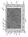
- FIG. 3represents a top view of a flexible circuit board layout 300 for a LED circuit.
- the flexible circuit board-based device 300includes a flexible circuit board 302 and various devices, including the parallel LED circuit 400 ( FIG. 4 ) or a series LED drive circuit or other circuits, may be mounted on the flexible circuit board 302 . While the flexible circuit board 302 is shown in a completely flat position, when in use, the flexible circuit board 302 may have the tabs 350 , 352 , and 354 folded along the dashed lines 308 and 310 . The folds may be at substantially 45 degrees such that the LEDs 304 face inwardly and are substantially perpendicular to the center region of the flexible circuit board 302 .
- a folded flexible circuit board 302may be configured as the circuit board 116 illustrated in the cross-section of FIG. 2 . Other configurations may also be used including a single fold configuration.
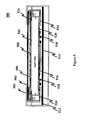
- the LCD device 500 with white LED'shas about one-third the LEDs as a comparable LCD device using non-white LEDs. In another aspect, the white LEDs have about 2.5 times the brightness of the non-white LEDs.
- the ESR 524 and the thermally conductive material 534are discussed below.
Landscapes
- Physics & Mathematics (AREA)
- General Physics & Mathematics (AREA)
- Optics & Photonics (AREA)
- Nonlinear Science (AREA)
- Mathematical Physics (AREA)
- Chemical & Material Sciences (AREA)
- Crystallography & Structural Chemistry (AREA)
- Liquid Crystal (AREA)
- Planar Illumination Modules (AREA)
Abstract
Description
| TABLE 1 | |
| Ref. | Description |
| C1 | A capacitor, for example a 1 uF capacitor. |
| C2-3 | A capacitor, for example a 0.01 uF capacitor. |
| Q1-4 | A PNP transistor, for example, a model MBT3906DW1T1 |
| transistor from Motorola, Inc. that is available in a dual package. | |
| Qn | A PNP transistor, for example, a model MBT3906DW1T1 |
| transistor from Motorola, Inc. that is available in a dual package. | |
| D1 | A Zener diode, for example a 3.3 volt Zener diode. |
| D2-3 | A light emitting diode. For example, white SIDELED Infineon |
| model LWA67C, a white LED from Infineon model LW E673 | |
| or LW E67C, red LED model LSA677-Q, green LED model | |
| LTA673-R24, or a blue LED LBA673-N24 all from Infineon | |
| Technology AG. | |
| Dn | A light emitting diode. For example, white SIDELED Infineon |
| model LWA67C, a white LED from Infineon model LW E673 | |
| or LW E67C, red LED model LSA677-Q, green LED model | |
| LTA673-R24, or a blue LED LBA673-N24 all from Infineon | |
| Technology AG. | |
| U1-4 | An operational amplifier, for example a model LMV321 |
| available from National Semiconductor Corp. or a model TLC | |
| 2274 Rail-to-Rail Operational Amplifier available from | |
| Texas Instruments, Inc. | |
| R1 | A resistor, for example a 4.99K Ohms resistor. Other resistance |
| values may also be used, for example, 0.5K to 50K Ohms. | |
| R2 | A resistor, for example a 5 Ohms resistor. Other resistance |
| values may also be used, for example, 0.5 to 500 Ohms. | |
| R3 | A resistor, for example a 100 Ohms resistor. Other resistance |
| values may also be used, for example, 0.1 to 10K Ohms. | |
| R4 | A resistor, for example a 16.5k Ohms resistor. Other resistance |
| values may also be used, for example, 165 to 1650K Ohms. | |
| R5 | A resistor, for example a 25K Ohms resistor. Other resistance |
| values may also be used, for example, 250 to 2,500K Ohms. | |
| R6 | A resistor, for example a 4.99K Ohms resistor. Other resistance |
| values may also be used, for example, 0.5K to 50K Ohms. | |
| R7 | A resistor, for example a 5 Ohms resistor. Other resistance |
| values may also be used, for example, 0.5 to 500 Ohms. | |
| R8 | A resistor, for example a 5 Ohms resistor. Other resistance |
| values may also be used, for example, 0.5 to 500 Ohms. | |
| Rn | A resistor, for example a 5 Ohms resistor. Other resistance |
| values may also be used, for example, 0.5 to 500 Ohms. | |
| R9-21 | A resistor, for example a 20K Ohms resistor. Other resistance |
| values may also be used, for example, 200 to 200K Ohms. | |
| RT1 | A resistor with a temperature dependant resistance, for example |
| KT230 available from Infineon Technology A.G. | |
Claims (9)
Priority Applications (4)
| Application Number | Priority Date | Filing Date | Title |
|---|---|---|---|
| US10/040,864US6930737B2 (en) | 2001-01-16 | 2001-12-28 | LED backlighting system |
| DE10201052ADE10201052B8 (en) | 2001-01-16 | 2002-01-14 | LED backlighting |
| GB0200653AGB2374714B (en) | 2001-01-16 | 2002-01-14 | LED backlighting system |
| US11/089,211US7193248B2 (en) | 2001-01-16 | 2005-03-23 | LED backlighting system |
Applications Claiming Priority (2)
| Application Number | Priority Date | Filing Date | Title |
|---|---|---|---|
| US26176001P | 2001-01-16 | 2001-01-16 | |
| US10/040,864US6930737B2 (en) | 2001-01-16 | 2001-12-28 | LED backlighting system |
Related Child Applications (1)
| Application Number | Title | Priority Date | Filing Date |
|---|---|---|---|
| US11/089,211DivisionUS7193248B2 (en) | 2001-01-16 | 2005-03-23 | LED backlighting system |
Publications (2)
| Publication Number | Publication Date |
|---|---|
| US20020140880A1 US20020140880A1 (en) | 2002-10-03 |
| US6930737B2true US6930737B2 (en) | 2005-08-16 |
Family
ID=26717533
Family Applications (2)
| Application Number | Title | Priority Date | Filing Date |
|---|---|---|---|
| US10/040,864Expired - LifetimeUS6930737B2 (en) | 2001-01-16 | 2001-12-28 | LED backlighting system |
| US11/089,211Expired - LifetimeUS7193248B2 (en) | 2001-01-16 | 2005-03-23 | LED backlighting system |
Family Applications After (1)
| Application Number | Title | Priority Date | Filing Date |
|---|---|---|---|
| US11/089,211Expired - LifetimeUS7193248B2 (en) | 2001-01-16 | 2005-03-23 | LED backlighting system |
Country Status (3)
| Country | Link |
|---|---|
| US (2) | US6930737B2 (en) |
| DE (1) | DE10201052B8 (en) |
| GB (1) | GB2374714B (en) |
Cited By (110)
| Publication number | Priority date | Publication date | Assignee | Title |
|---|---|---|---|---|
| US20050018416A1 (en)* | 2001-12-25 | 2005-01-27 | Toshio Amaya | Illumination unit and liquid crystal display device using the unit |
| US20050151059A1 (en)* | 2004-01-13 | 2005-07-14 | Seiko Epson Corporation | Electro-optical device, method for driving the same, and electronic apparatus |
| US20060038511A1 (en)* | 2004-08-18 | 2006-02-23 | Sony Corporation | Control device |
| US20060104090A1 (en)* | 2004-11-12 | 2006-05-18 | Harris Corporation | LED light engine for backlighting a liquid crystal display |
| US20060232995A1 (en)* | 2005-01-28 | 2006-10-19 | Au Optronics Corporation | Backlight system and LCD using the same |
| WO2006055165A3 (en)* | 2004-11-12 | 2006-11-02 | Harris Corp | Led light engine for backlighting a liquid crystal display |
| US20060290875A1 (en)* | 2005-06-27 | 2006-12-28 | Shives Gary D | Optimized frame system for a display device |
| US20070115419A1 (en)* | 2005-11-23 | 2007-05-24 | Song Hyo S | Portable display device |
| US20070127262A1 (en)* | 2004-06-30 | 2007-06-07 | 3M Innovative Properties Company | Phosphor based illumination system having a plurality of light guides and a display using same |
| US20070153548A1 (en)* | 2004-05-21 | 2007-07-05 | Sharp Kabushiki Kaisha | Backlight unit and liquid crystal display device having the same |
| US20070164653A1 (en)* | 2006-01-13 | 2007-07-19 | Byong-Gwon Song | Field emission type backlight unit and method of manufacturing upper panel thereof |
| US20070195549A1 (en)* | 2004-06-30 | 2007-08-23 | 3M Innovative Properties Company | Phosphor Based Illumination System Having a Plurality of Light Guides and a Display Using Same |
| US20070215890A1 (en)* | 2006-03-17 | 2007-09-20 | Philips Lumileds Lighting Company, Llc | White LED for backlight with phosphor plates |
| WO2007056599A3 (en)* | 2005-11-09 | 2007-11-15 | Cooligy Inc | Liquid cooling for backlit displays |
| US20070274098A1 (en)* | 2004-06-30 | 2007-11-29 | 3M Innovative Properties Company | Phosphor based illumination system having a long pass reflector and method of making same |
| US20070277364A1 (en)* | 2006-06-02 | 2007-12-06 | Chicony Electronics Co. Ltd. | Method of fabricating an electronic module having a side contact |
| US20080024076A1 (en)* | 2006-07-31 | 2008-01-31 | Powerdsine, Ltd. - Microsemi Corporation | Color Control for Scanning Backlight |
| US20080068520A1 (en)* | 2006-03-09 | 2008-03-20 | Minikey Danny L Jr | Vehicle Rearview Mirror Assembly Including a High Intensity Display |
| US20080074580A1 (en)* | 2006-09-21 | 2008-03-27 | Chih-Li Chang | Liquid crystal display and backlight module |
| US20080136770A1 (en)* | 2006-12-07 | 2008-06-12 | Microsemi Corp. - Analog Mixed Signal Group Ltd. | Thermal Control for LED Backlight |
| US20080158207A1 (en)* | 2006-12-29 | 2008-07-03 | Wintek Corpo.Ration | Field sequential liquid crystal display and driving method thereof |
| US20080198299A1 (en)* | 2007-02-15 | 2008-08-21 | Samsung Electronics Co., Ltd | Light source unit, liquid crystal display having the same, and method thereof |
| US20080231773A1 (en)* | 2007-03-20 | 2008-09-25 | Casio Computer Co., Ltd. | Surface light source which selectively irradiates two linearly polarized light beams in polarized states different from each other and liquid crystal display apparatus using the same |
| US20080238341A1 (en)* | 2007-03-29 | 2008-10-02 | Microsemi Corp. - Analog Mixed Signal Group Ltd. | Color Control for Dynamic Scanning Backlight |
| US20090001252A1 (en)* | 2007-06-26 | 2009-01-01 | Microsemi Corp. - Analog Mixed Signal Group Ltd. | Brightness Control for Dynamic Scanning Backlight |
| US20090116244A1 (en)* | 2007-11-06 | 2009-05-07 | Industrial Technology Research Institute | Light-emitting module |
| US20090231354A1 (en)* | 2008-03-13 | 2009-09-17 | Microsemi Corp. - Analog Mixed Signal Group, Ltd. | A Color Controller for a Luminaire |
| US20090279020A1 (en)* | 2006-06-01 | 2009-11-12 | Sharp Kabushiki Kaisha | Surface-area light source device and liquid crystal display device using the same |
| US20090302781A1 (en)* | 2008-06-10 | 2009-12-10 | Microsemi Corp. - Analog Mixed Signal Group Ltd. | Color manager for backlight systems operative at multiple current levels |
| US20100002418A1 (en)* | 2008-07-02 | 2010-01-07 | Chunghwa Picture Tubes, Ltd. | Backlight module |
| US20100007817A1 (en)* | 2008-07-08 | 2010-01-14 | Lg Display Co., Ltd. | Liquid crystal display device |
| US20100045899A1 (en)* | 2008-08-22 | 2010-02-25 | Gentex Corporation | Discrete led backlight control for a reduced power lcd display system |
| US20100141148A1 (en)* | 2007-02-26 | 2010-06-10 | Koninklijke Philips Electronics N.V. | Driving a lighting device |
| US7746634B2 (en) | 2007-08-07 | 2010-06-29 | Cooligy Inc. | Internal access mechanism for a server rack |
| US7815326B2 (en) | 2002-06-06 | 2010-10-19 | Donnelly Corporation | Interior rearview mirror system |
| US7822543B2 (en) | 2000-03-02 | 2010-10-26 | Donnelly Corporation | Video display system for vehicle |
| US7821697B2 (en) | 1994-05-05 | 2010-10-26 | Donnelly Corporation | Exterior reflective mirror element for a vehicular rearview mirror assembly |
| US7826123B2 (en) | 2002-09-20 | 2010-11-02 | Donnelly Corporation | Vehicular interior electrochromic rearview mirror assembly |
| US7832882B2 (en) | 2002-06-06 | 2010-11-16 | Donnelly Corporation | Information mirror system |
| US7855755B2 (en) | 2005-11-01 | 2010-12-21 | Donnelly Corporation | Interior rearview mirror assembly with display |
| US7859737B2 (en) | 2002-09-20 | 2010-12-28 | Donnelly Corporation | Interior rearview mirror system for a vehicle |
| US7864399B2 (en) | 2002-09-20 | 2011-01-04 | Donnelly Corporation | Reflective mirror assembly |
| US7871169B2 (en) | 1994-05-05 | 2011-01-18 | Donnelly Corporation | Vehicular signal mirror |
| US7888629B2 (en) | 1998-01-07 | 2011-02-15 | Donnelly Corporation | Vehicular accessory mounting system with a forwardly-viewing camera |
| US7898719B2 (en) | 2003-10-02 | 2011-03-01 | Donnelly Corporation | Rearview mirror assembly for vehicle |
| US7898398B2 (en) | 1997-08-25 | 2011-03-01 | Donnelly Corporation | Interior mirror system |
| US7906756B2 (en) | 2002-05-03 | 2011-03-15 | Donnelly Corporation | Vehicle rearview mirror system |
| US7916009B2 (en) | 1998-01-07 | 2011-03-29 | Donnelly Corporation | Accessory mounting system suitable for use in a vehicle |
| US7914188B2 (en) | 1997-08-25 | 2011-03-29 | Donnelly Corporation | Interior rearview mirror system for a vehicle |
| US7924389B2 (en)* | 2007-06-07 | 2011-04-12 | Samsung Electronics Co., Ltd. | Liquid crystal display with housing exposed flexible printed circuit |
| US7926960B2 (en) | 1999-11-24 | 2011-04-19 | Donnelly Corporation | Interior rearview mirror system for vehicle |
| US20110115400A1 (en)* | 2009-11-17 | 2011-05-19 | Harrison Daniel J | Led dimmer control |
| US8019505B2 (en) | 2003-10-14 | 2011-09-13 | Donnelly Corporation | Vehicle information display |
| US8044776B2 (en) | 2000-03-02 | 2011-10-25 | Donnelly Corporation | Rear vision system for vehicle |
| US8072318B2 (en) | 2001-01-23 | 2011-12-06 | Donnelly Corporation | Video mirror system for vehicle |
| US8083386B2 (en) | 2001-01-23 | 2011-12-27 | Donnelly Corporation | Interior rearview mirror assembly with display device |
| US8154418B2 (en) | 2008-03-31 | 2012-04-10 | Magna Mirrors Of America, Inc. | Interior rearview mirror system |
| US8194133B2 (en) | 2000-03-02 | 2012-06-05 | Donnelly Corporation | Vehicular video mirror system |
| US20120188789A1 (en)* | 2011-01-21 | 2012-07-26 | JVC Kenwood Corporation | Backlight device and image display device |
| US8288711B2 (en) | 1998-01-07 | 2012-10-16 | Donnelly Corporation | Interior rearview mirror system with forwardly-viewing camera and a control |
| US8294975B2 (en) | 1997-08-25 | 2012-10-23 | Donnelly Corporation | Automotive rearview mirror assembly |
| US8358085B2 (en) | 2009-01-13 | 2013-01-22 | Terralux, Inc. | Method and device for remote sensing and control of LED lights |
| US8462204B2 (en) | 1995-05-22 | 2013-06-11 | Donnelly Corporation | Vehicular vision system |
| US8503062B2 (en) | 2005-05-16 | 2013-08-06 | Donnelly Corporation | Rearview mirror element assembly for vehicle |
| TWI407199B (en)* | 2010-10-29 | 2013-09-01 | Au Optronics Corp | Flat panel display structure and manufacturing method thereof |
| US8525703B2 (en) | 1998-04-08 | 2013-09-03 | Donnelly Corporation | Interior rearview mirror system |
| US20140085564A1 (en)* | 2012-09-26 | 2014-03-27 | Apple Inc. | Computer led bar and thermal architecture features |
| US8860330B1 (en) | 2013-04-08 | 2014-10-14 | Dialog Semiconductor Gmbh | Programmable current source with optimized compliance region for efficient backlighting in portable applications |
| US8879139B2 (en) | 2012-04-24 | 2014-11-04 | Gentex Corporation | Display mirror assembly |
| US9019091B2 (en) | 1999-11-24 | 2015-04-28 | Donnelly Corporation | Interior rearview mirror system |
| US9099046B2 (en) | 2009-02-24 | 2015-08-04 | Dolby Laboratories Licensing Corporation | Apparatus for providing light source modulation in dual modulator displays |
| US9192011B2 (en) | 2011-12-16 | 2015-11-17 | Terralux, Inc. | Systems and methods of applying bleed circuits in LED lamps |
| US20160031462A1 (en)* | 2014-07-29 | 2016-02-04 | Electro-Motive Diesel, Inc. | Apparatus for displaying road number for a locomotive |
| US9265119B2 (en) | 2013-06-17 | 2016-02-16 | Terralux, Inc. | Systems and methods for providing thermal fold-back to LED lights |
| US9326346B2 (en) | 2009-01-13 | 2016-04-26 | Terralux, Inc. | Method and device for remote sensing and control of LED lights |
| US9342058B2 (en) | 2010-09-16 | 2016-05-17 | Terralux, Inc. | Communication with lighting units over a power bus |
| US9487144B2 (en) | 2008-10-16 | 2016-11-08 | Magna Mirrors Of America, Inc. | Interior mirror assembly with display |
| US9511715B2 (en) | 2014-01-31 | 2016-12-06 | Gentex Corporation | Backlighting assembly for display for reducing cross-hatching |
| US9575315B2 (en) | 2013-09-24 | 2017-02-21 | Gentex Corporation | Display mirror assembly |
| US9596738B2 (en) | 2010-09-16 | 2017-03-14 | Terralux, Inc. | Communication with lighting units over a power bus |
| US9598018B2 (en) | 2013-03-15 | 2017-03-21 | Gentex Corporation | Display mirror assembly |
| USD783480S1 (en) | 2014-12-05 | 2017-04-11 | Gentex Corporation | Rearview device |
| US9694752B2 (en) | 2014-11-07 | 2017-07-04 | Gentex Corporation | Full display mirror actuator |
| US9694751B2 (en) | 2014-09-19 | 2017-07-04 | Gentex Corporation | Rearview assembly |
| US9720278B2 (en) | 2015-01-22 | 2017-08-01 | Gentex Corporation | Low cost optical film stack |
| US9744907B2 (en) | 2014-12-29 | 2017-08-29 | Gentex Corporation | Vehicle vision system having adjustable displayed field of view |
| USD797627S1 (en) | 2015-10-30 | 2017-09-19 | Gentex Corporation | Rearview mirror device |
| USD798207S1 (en) | 2015-10-30 | 2017-09-26 | Gentex Corporation | Rearview mirror assembly |
| USD800618S1 (en) | 2015-11-02 | 2017-10-24 | Gentex Corporation | Toggle paddle for a rear view device |
| US9834146B2 (en) | 2014-04-01 | 2017-12-05 | Gentex Corporation | Automatic display mirror assembly |
| US9874660B2 (en) | 2014-09-11 | 2018-01-23 | Industrial Technology Research Institute | Hardcoat composition and polarizer and display device applying the same |
| USD809984S1 (en) | 2016-12-07 | 2018-02-13 | Gentex Corporation | Rearview assembly |
| USD817238S1 (en) | 2016-04-29 | 2018-05-08 | Gentex Corporation | Rearview device |
| US9994156B2 (en) | 2015-10-30 | 2018-06-12 | Gentex Corporation | Rearview device |
| US9995854B2 (en) | 2015-04-20 | 2018-06-12 | Gentex Corporation | Rearview assembly with applique |
| US10025138B2 (en) | 2016-06-06 | 2018-07-17 | Gentex Corporation | Illuminating display with light gathering structure |
| US10071689B2 (en) | 2014-11-13 | 2018-09-11 | Gentex Corporation | Rearview mirror system with a display |
| US10112540B2 (en) | 2015-05-18 | 2018-10-30 | Gentex Corporation | Full display rearview device |
| US10131279B2 (en) | 2014-12-03 | 2018-11-20 | Gentex Corporation | Display mirror assembly with an RF shield bezel |
| US10162217B2 (en) | 2005-06-13 | 2018-12-25 | Samsung Electronics Co., Ltd. | Liquid crystal display device having improved cooling efficiency |
| USRE47196E1 (en) | 2006-03-13 | 2019-01-08 | Samsung Electronics Co., Ltd. | Liquid crystal panel assembly and liquid crystal display apparatus having the same |
| US10247870B2 (en)* | 2015-05-04 | 2019-04-02 | Himax Display, Inc. | Wearable display apparatus comprising an optical assembly having an optical integrator rod |
| USD845851S1 (en) | 2016-03-31 | 2019-04-16 | Gentex Corporation | Rearview device |
| USD854473S1 (en) | 2016-12-16 | 2019-07-23 | Gentex Corporation | Rearview assembly |
| US10685623B2 (en) | 2015-10-30 | 2020-06-16 | Gentex Corporation | Toggle paddle |
| US10705332B2 (en) | 2014-03-21 | 2020-07-07 | Gentex Corporation | Tri-modal display mirror assembly |
| US10735638B2 (en) | 2017-03-17 | 2020-08-04 | Gentex Corporation | Dual display reverse camera system |
| US11178353B2 (en) | 2015-06-22 | 2021-11-16 | Gentex Corporation | System and method for processing streamed video images to correct for flicker of amplitude-modulated lights |
| US11800050B2 (en) | 2016-12-30 | 2023-10-24 | Gentex Corporation | Full display mirror with on-demand spotter view |
| US11994272B2 (en) | 2021-08-20 | 2024-05-28 | Gentex Corporation | Lighting assembly and illumination system having a lighting assembly |
Families Citing this family (150)
| Publication number | Priority date | Publication date | Assignee | Title |
|---|---|---|---|---|
| US6590561B1 (en) | 2001-05-26 | 2003-07-08 | Garmin Ltd. | Computer program, method, and device for controlling the brightness of a display |
| US6943771B2 (en) | 2001-05-26 | 2005-09-13 | Garmin Ltd. | Computer program, method, and device for controlling the brightness of a display |
| EP1313353A1 (en)* | 2001-11-19 | 2003-05-21 | Nokia Corporation | Method and device for operating a light emitting diode |
| DE10205796C1 (en)* | 2002-02-13 | 2003-10-30 | Behr Hella Thermocontrol Gmbh | Operating device for automobile heating and/or air-conditioning has display field provided by insert in front plate illuminated using non-visible electromagnetic radiation via wavelength converter |
| US6841947B2 (en)* | 2002-05-14 | 2005-01-11 | Garmin At, Inc. | Systems and methods for controlling brightness of an avionics display |
| KR100628264B1 (en)* | 2002-09-26 | 2006-09-27 | 엘지.필립스 엘시디 주식회사 | Backlight Unit of LCD |
| DE20219483U1 (en) | 2002-12-16 | 2003-05-08 | FER Fahrzeugelektrik GmbH, 99817 Eisenach | vehicle light |
| DE10260692B4 (en)* | 2002-12-23 | 2009-05-20 | Continental Automotive Gmbh | liquid-crystal display |
| US7245072B2 (en)* | 2003-01-27 | 2007-07-17 | 3M Innovative Properties Company | Phosphor based light sources having a polymeric long pass reflector |
| US7118438B2 (en)* | 2003-01-27 | 2006-10-10 | 3M Innovative Properties Company | Methods of making phosphor based light sources having an interference reflector |
| US20040145312A1 (en)* | 2003-01-27 | 2004-07-29 | 3M Innovative Properties Company | Phosphor based light source having a flexible short pass reflector |
| US7312560B2 (en) | 2003-01-27 | 2007-12-25 | 3M Innovative Properties | Phosphor based light sources having a non-planar long pass reflector and method of making |
| US7091661B2 (en)* | 2003-01-27 | 2006-08-15 | 3M Innovative Properties Company | Phosphor based light sources having a reflective polarizer |
| US7157839B2 (en) | 2003-01-27 | 2007-01-02 | 3M Innovative Properties Company | Phosphor based light sources utilizing total internal reflection |
| JP2006516828A (en)* | 2003-01-27 | 2006-07-06 | スリーエム イノベイティブ プロパティズ カンパニー | Phosphorescent light source element and manufacturing method |
| US7091653B2 (en) | 2003-01-27 | 2006-08-15 | 3M Innovative Properties Company | Phosphor based light sources having a non-planar long pass reflector |
| US7210977B2 (en) | 2003-01-27 | 2007-05-01 | 3M Innovative Properties Comapny | Phosphor based light source component and method of making |
| JP3935095B2 (en)* | 2003-03-20 | 2007-06-20 | 株式会社ソフィア | Image display device and light source unit |
| CA2523544A1 (en) | 2003-04-30 | 2004-11-18 | Cree, Inc. | High powered light emitter packages with compact optics |
| US7005679B2 (en)* | 2003-05-01 | 2006-02-28 | Cree, Inc. | Multiple component solid state white light |
| KR20060028701A (en)* | 2003-06-27 | 2006-03-31 | 코닌클리즈케 필립스 일렉트로닉스 엔.브이. | Luminous body |
| DE10345884A1 (en)* | 2003-09-30 | 2005-05-12 | Siemens Ag | Display with backlight unit |
| JP2005158795A (en)* | 2003-11-20 | 2005-06-16 | Sumitomo Electric Ind Ltd | Light emitting diode and semiconductor light emitting device |
| US10499465B2 (en)* | 2004-02-25 | 2019-12-03 | Lynk Labs, Inc. | High frequency multi-voltage and multi-brightness LED lighting devices and systems and methods of using same |
| US7808011B2 (en)* | 2004-03-19 | 2010-10-05 | Koninklijke Philips Electronics N.V. | Semiconductor light emitting devices including in-plane light emitting layers |
| US7408201B2 (en)* | 2004-03-19 | 2008-08-05 | Philips Lumileds Lighting Company, Llc | Polarized semiconductor light emitting device |
| DE102004014788A1 (en)* | 2004-03-24 | 2005-10-27 | Andreas Huck | Illumination for a watch face is provide by a light emitting diode with output into an optical conductor |
| US7534633B2 (en)* | 2004-07-02 | 2009-05-19 | Cree, Inc. | LED with substrate modifications for enhanced light extraction and method of making same |
| JP2006030783A (en)* | 2004-07-20 | 2006-02-02 | Alps Electric Co Ltd | Liquid crystal display device |
| US8797192B2 (en)* | 2004-08-16 | 2014-08-05 | Wai-Lin Maw | Virtual keypad input device |
| US20060082701A1 (en)* | 2004-10-18 | 2006-04-20 | Tong Li | Module for liquid crystal displays |
| WO2006047306A1 (en)* | 2004-10-22 | 2006-05-04 | Johnson Controls Technology Company | Lamp with emissive material outside of light source |
| US7318298B2 (en)* | 2004-10-29 | 2008-01-15 | Cosco Management, Inc. | Illuminated security gate unit |
| JP2008521232A (en)* | 2004-11-17 | 2008-06-19 | コーニンクレッカ フィリップス エレクトロニクス エヌ ヴィ | Light source and lighting device having at least one light emitting element |
| US20070045640A1 (en)* | 2005-08-23 | 2007-03-01 | Erchak Alexei A | Light emitting devices for liquid crystal displays |
| WO2006096671A2 (en)* | 2005-03-08 | 2006-09-14 | Luminus Devices, Inc. | Light emitting devices for liquid crystal displays |
| US20060221271A1 (en)* | 2005-04-04 | 2006-10-05 | Tsai Chen C | Structure of LCD backlight module |
| JP5057692B2 (en)* | 2005-04-27 | 2012-10-24 | サムソン エルイーディー カンパニーリミテッド. | Backlight unit using light emitting diode |
| WO2006131924A2 (en) | 2005-06-07 | 2006-12-14 | Oree, Advanced Illumination Solutions Inc. | Illumination apparatus |
| US8215815B2 (en)* | 2005-06-07 | 2012-07-10 | Oree, Inc. | Illumination apparatus and methods of forming the same |
| US8272758B2 (en)* | 2005-06-07 | 2012-09-25 | Oree, Inc. | Illumination apparatus and methods of forming the same |
| US9104058B2 (en)* | 2005-06-27 | 2015-08-11 | Graftech International Holdings Inc. | Optimized frame system for a liquid crystal display device |
| US9087669B2 (en)* | 2005-06-27 | 2015-07-21 | Graftech International Holdings Inc. | Display device having improved properties |
| DE102005033982A1 (en)* | 2005-07-20 | 2007-02-01 | Siemens Ag | display unit |
| US7513669B2 (en)* | 2005-08-01 | 2009-04-07 | Avago Technologies General Ip (Singapore) Pte. Ltd. | Light source for LCD back-lit displays |
| EP1922574B1 (en)* | 2005-08-31 | 2018-10-10 | Universal Avionics Systems Corporation | Led backlight for flat panel display |
| US20070053179A1 (en)* | 2005-09-08 | 2007-03-08 | Pang Slew I | Low profile light source utilizing a flexible circuit carrier |
| US20070097066A1 (en)* | 2005-10-27 | 2007-05-03 | Ward Calvin B | LCD display utilizing light emitters with variable light output |
| KR20070054825A (en)* | 2005-11-24 | 2007-05-30 | 엘지이노텍 주식회사 | Lighting device using LED |
| CN101351891B (en) | 2005-12-22 | 2014-11-19 | 科锐公司 | lighting device |
| US7540616B2 (en)* | 2005-12-23 | 2009-06-02 | 3M Innovative Properties Company | Polarized, multicolor LED-based illumination source |
| EP1969284B1 (en)* | 2005-12-27 | 2012-06-13 | Showa Denko K.K. | Flat light source device and display device using the same |
| US8513875B2 (en) | 2006-04-18 | 2013-08-20 | Cree, Inc. | Lighting device and lighting method |
| US9084328B2 (en) | 2006-12-01 | 2015-07-14 | Cree, Inc. | Lighting device and lighting method |
| US7540628B2 (en)* | 2006-04-24 | 2009-06-02 | Novicomm, Inc. | Illuminated panels and methods therefor |
| WO2007148298A1 (en)* | 2006-06-22 | 2007-12-27 | Koninklijke Philips Electronics N.V. | Drive circuit for driving a load with pulsed current |
| KR20080013127A (en)* | 2006-08-07 | 2008-02-13 | 삼성전자주식회사 | Backlight unit and liquid crystal display having the same |
| KR20080027599A (en)* | 2006-09-25 | 2008-03-28 | 삼성전자주식회사 | Backlight assembly and display device including same |
| US7605880B2 (en)* | 2006-10-27 | 2009-10-20 | Chunghwa Picture Tubes, Ltd. | Liquid crystal display |
| US9441793B2 (en) | 2006-12-01 | 2016-09-13 | Cree, Inc. | High efficiency lighting device including one or more solid state light emitters, and method of lighting |
| US7461962B2 (en)* | 2007-01-22 | 2008-12-09 | Samsung Electronics Co., Ltd. | Backlight assembly, display device provided with the same, and method thereof |
| US20080186732A1 (en)* | 2007-02-03 | 2008-08-07 | Awai George K | Light emitting diode modules for illuminated panels |
| US20080197369A1 (en)* | 2007-02-20 | 2008-08-21 | Cree, Inc. | Double flip semiconductor device and method for fabrication |
| DE102007009532A1 (en)* | 2007-02-27 | 2008-08-28 | Osram Opto Semiconductors Gmbh | Radiation-emitting semiconductor component i.e. red luminous LED, controlling method for operating component, involves generating pulse-shaped electrical operating current for operating radiation-emitting semiconductor component |
| US8792070B2 (en)* | 2007-03-21 | 2014-07-29 | Honeywell International Inc. | Polarization plate for use in a liquid crystal display |
| KR101375851B1 (en)* | 2007-06-01 | 2014-04-01 | 엘지디스플레이 주식회사 | Liquid crystal display device |
| US20090015748A1 (en)* | 2007-07-10 | 2009-01-15 | Nec Lcd Technologies, Ltd | Liquid crystal display device |
| CN101408290A (en)* | 2007-10-11 | 2009-04-15 | 富士迈半导体精密工业(上海)有限公司 | LED lighting device |
| US9431589B2 (en)* | 2007-12-14 | 2016-08-30 | Cree, Inc. | Textured encapsulant surface in LED packages |
| US7907804B2 (en)* | 2007-12-19 | 2011-03-15 | Oree, Inc. | Elimination of stitch artifacts in a planar illumination area |
| US8182128B2 (en)* | 2007-12-19 | 2012-05-22 | Oree, Inc. | Planar white illumination apparatus |
| US8104945B2 (en)* | 2007-12-27 | 2012-01-31 | Samsung Led Co., Ltd. | Backlight unit implementing local dimming for liquid crystal display device |
| KR20090074478A (en)* | 2008-01-02 | 2009-07-07 | 삼성전자주식회사 | Light source module for display device and display device including same |
| JP5161892B2 (en)* | 2008-02-01 | 2013-03-13 | 株式会社クラレ | Surface light source element and image display device having the same |
| US20090225566A1 (en)* | 2008-03-05 | 2009-09-10 | Micha Zimmermann | Illumination apparatus and methods of forming the same |
| US8085359B2 (en)* | 2008-04-16 | 2011-12-27 | Honeywell International Inc. | Folded backlight systems having low index regions that prevent light failing to meet total internal reflection conditions from entering a plate portion and liquid crystal displays using the same |
| US8021008B2 (en)* | 2008-05-27 | 2011-09-20 | Abl Ip Holding Llc | Solid state lighting using quantum dots in a liquid |
| US8028537B2 (en)* | 2009-05-01 | 2011-10-04 | Abl Ip Holding Llc | Heat sinking and flexible circuit board, for solid state light fixture utilizing an optical cavity |
| US8994615B2 (en)* | 2008-06-06 | 2015-03-31 | Dolby Laboratories Licensing Corporation | Apparatus and methods for driving solid-state illumination sources |
| US8297786B2 (en)* | 2008-07-10 | 2012-10-30 | Oree, Inc. | Slim waveguide coupling apparatus and method |
| US8301002B2 (en)* | 2008-07-10 | 2012-10-30 | Oree, Inc. | Slim waveguide coupling apparatus and method |
| US8547321B2 (en)* | 2008-07-23 | 2013-10-01 | Apple Inc. | LED backlight driver synchronization and power reduction |
| JP5261056B2 (en)* | 2008-07-28 | 2013-08-14 | パナソニック株式会社 | Backlight device |
| KR101502420B1 (en)* | 2008-09-22 | 2015-03-25 | 삼성디스플레이 주식회사 | Light source module and display device having the same |
| US9262958B2 (en) | 2008-11-06 | 2016-02-16 | E.F. Johnson Company | Control head with electroluminescent panel in land mobile radio |
| US20100109562A1 (en)* | 2008-11-06 | 2010-05-06 | StarChips Technology Inc. | Backlight module and light-emitting device thereof |
| DE102008057347A1 (en)* | 2008-11-14 | 2010-05-20 | Osram Opto Semiconductors Gmbh | Optoelectronic device |
| WO2010059579A1 (en)* | 2008-11-19 | 2010-05-27 | 3M Innovative Properties Company | High transmission flux leveling multilayer optical film and related constructions |
| BRPI1005305A2 (en) | 2009-01-28 | 2019-09-24 | Koninl Philips Electronics Nv | lighting system, remote phosphor layer. scatter layer, luminaire, display device and method of correcting at least partially a light-emitting characteristic from at least one light source in a lighting system |
| US20100208469A1 (en)* | 2009-02-10 | 2010-08-19 | Yosi Shani | Illumination surfaces with reduced linear artifacts |
| EP2228257A1 (en)* | 2009-03-13 | 2010-09-15 | Alfred Held | Light device and method of assembling a light device |
| US8624527B1 (en) | 2009-03-27 | 2014-01-07 | Oree, Inc. | Independently controllable illumination device |
| US8096671B1 (en) | 2009-04-06 | 2012-01-17 | Nmera, Llc | Light emitting diode illumination system |
| JP2010243825A (en)* | 2009-04-07 | 2010-10-28 | Hitachi Displays Ltd | Liquid crystal display |
| KR100966874B1 (en)* | 2009-04-27 | 2010-06-29 | 삼성전자주식회사 | Back light assembly and liquid crystal display comprising the same |
| KR20100121861A (en)* | 2009-05-11 | 2010-11-19 | 삼성전자주식회사 | Light emitting unit and back light unit having the same |
| US20100320904A1 (en)* | 2009-05-13 | 2010-12-23 | Oree Inc. | LED-Based Replacement Lamps for Incandescent Fixtures |
| WO2010150202A2 (en) | 2009-06-24 | 2010-12-29 | Oree, Advanced Illumination Solutions Inc. | Illumination apparatus with high conversion efficiency and methods of forming the same |
| TWI417615B (en)* | 2009-07-07 | 2013-12-01 | Chi Lin Optoelectronics Co Ltd | Edge light type backlight module |
| US8836888B2 (en)* | 2009-12-15 | 2014-09-16 | Gentex Corporation | Modular light source/electronics and automotive rearview assemblies using the same |
| WO2011086790A1 (en)* | 2010-01-18 | 2011-07-21 | シャープ株式会社 | Lighting device, display apparatus, and television receiver apparatus |
| KR101047628B1 (en)* | 2010-06-03 | 2011-07-08 | 엘지이노텍 주식회사 | Backlight Unit and Display Device |
| TWI471504B (en)* | 2010-10-27 | 2015-02-01 | Young Lighting Technology Corp | Flat light source module |
| TWI493140B (en)* | 2010-11-05 | 2015-07-21 | Lextar Electronics Corp | Lamp device with color-changeable filter |
| US20120113675A1 (en)* | 2010-11-05 | 2012-05-10 | Lextar Electronics Corporation | Lamp device with color-changeable filter |
| US9274269B2 (en) | 2011-05-31 | 2016-03-01 | Lg Innotek Co., Ltd. | Backlight unit and display device |
| KR101808191B1 (en)* | 2011-08-26 | 2017-12-13 | 삼성전자 주식회사 | A Backlight Unit and A Liquid Crystal Display having the Backlight Unit |
| JP2013050470A (en)* | 2011-08-30 | 2013-03-14 | Funai Electric Co Ltd | Thin display device |
| KR101251815B1 (en)* | 2011-11-07 | 2013-04-09 | 엘지이노텍 주식회사 | Optical sheet and display device having the same |
| US8591072B2 (en) | 2011-11-16 | 2013-11-26 | Oree, Inc. | Illumination apparatus confining light by total internal reflection and methods of forming the same |
| US9244299B2 (en)* | 2011-11-22 | 2016-01-26 | Shenzhen China Star Optoelectronics Technology Co., Ltd. | Backlight module of display device |
| CN102620194A (en)* | 2012-03-12 | 2012-08-01 | 深圳市华星光电技术有限公司 | Backlight module and liquid crystal display device |
| US20130258708A1 (en)* | 2012-04-01 | 2013-10-03 | Shenzhen China str Optoelectronics Technology Co., LTD. | Backlight Module |
| JP2013218125A (en)* | 2012-04-10 | 2013-10-24 | Japan Display Inc | Liquid-crystal display |
| US20130328942A1 (en)* | 2012-06-12 | 2013-12-12 | Stephen Chen | Head up display for a vehicle |
| WO2014006501A1 (en) | 2012-07-03 | 2014-01-09 | Yosi Shani | Planar remote phosphor illumination apparatus |
| DE102012212557A1 (en)* | 2012-07-18 | 2014-01-23 | Osram Opto Semiconductors Gmbh | Device for providing electromagnetic radiation for illumination device e.g. LED of headlight for motor car, has uncoupling region that deflects striking beam paths of electromagnetic radiation in direction out of beam guide |
| US9353917B2 (en) | 2012-09-14 | 2016-05-31 | Cree, Inc. | High efficiency lighting device including one or more solid state light emitters, and method of lighting |
| US9558721B2 (en) | 2012-10-15 | 2017-01-31 | Apple Inc. | Content-based adaptive refresh schemes for low-power displays |
| CN103032766A (en)* | 2012-12-12 | 2013-04-10 | 京东方科技集团股份有限公司 | Backlight module and display device |
| US9153171B2 (en) | 2012-12-17 | 2015-10-06 | LuxVue Technology Corporation | Smart pixel lighting and display microcontroller |
| US20140204309A1 (en)* | 2013-01-24 | 2014-07-24 | Kabushiki Kaisha Toshiba | Electronic apparatus |
| US9179554B2 (en)* | 2013-04-09 | 2015-11-03 | Whirlpool Corporation | Appliance displays having modular light guides and methods of assembling the same |
| CN104241262B (en) | 2013-06-14 | 2020-11-06 | 惠州科锐半导体照明有限公司 | Light emitting device and display device |
| KR102148718B1 (en)* | 2013-12-18 | 2020-08-27 | 삼성전자주식회사 | Display device |
| TWI588572B (en)* | 2014-03-31 | 2017-06-21 | 瑞儀光電股份有限公司 | Light source module |
| US9741286B2 (en) | 2014-06-03 | 2017-08-22 | Apple Inc. | Interactive display panel with emitting and sensing diodes |
| US9570002B2 (en) | 2014-06-17 | 2017-02-14 | Apple Inc. | Interactive display panel with IR diodes |
| WO2016111492A1 (en)* | 2015-01-05 | 2016-07-14 | Samsung Electronics Co., Ltd. | Display module and display apparatus having the same |
| KR102318262B1 (en) | 2015-03-11 | 2021-10-27 | 삼성디스플레이 주식회사 | Backlight unit and display device comprising the same |
| US9501174B2 (en)* | 2015-04-10 | 2016-11-22 | Apple Inc. | Temperature sensing display assemblies |
| JP6680868B2 (en) | 2015-08-17 | 2020-04-15 | インフィニット アースロスコピー インコーポレーテッド, リミテッド | light source |
| WO2017087448A1 (en) | 2015-11-16 | 2017-05-26 | Infinite Arthroscopy Inc, Limited | Wireless medical imaging system |
| KR20180086262A (en)* | 2015-12-17 | 2018-07-30 | 쓰리엠 이노베이티브 프로퍼티즈 컴파니 | A mirror comprising a reflective backlit display |
| US10344954B1 (en) | 2016-03-02 | 2019-07-09 | Cooledge Lighting Inc. | Lighting systems incorporating connections for signal and power transmission |
| US11274823B1 (en) | 2016-03-02 | 2022-03-15 | Cooledge Lighting, Inc. | Lighting systems incorporating connections for signal and power transmission |
| US10746358B1 (en) | 2016-03-02 | 2020-08-18 | Cooledge Lighting Inc. | Lighting systems incorporating connections for signal and power transmission |
| KR102605921B1 (en)* | 2016-09-27 | 2023-11-27 | 삼성디스플레이 주식회사 | Backlight unit and display apparatus including the same |
| US10288797B1 (en)* | 2016-10-24 | 2019-05-14 | Amazon Technologies, Inc. | Structural alignment features for light emitting diode arrays |
| CN106491042B (en)* | 2016-11-14 | 2019-01-08 | 浙江工业大学 | Processing method is moved down at a kind of swing type window wiping robot glass edge |
| CN106491039B (en)* | 2016-11-14 | 2019-01-08 | 浙江工业大学 | A kind of swing type window wiping robot glass edge detection method |
| EP4250721A3 (en) | 2017-02-15 | 2024-02-07 | Lazurite Holdings LLC | Wireless medical imaging system comprising a head unit and a light cable that comprises an integrated light source |
| WO2018158110A1 (en)* | 2017-03-02 | 2018-09-07 | Philips Lighting Holding B.V. | Luminaire with light guide |
| WO2018162268A1 (en) | 2017-03-09 | 2018-09-13 | Philips Lighting Holding B.V. | Core-shell filament for printing smooth fdm 3d items |
| JP7203366B2 (en)* | 2017-03-16 | 2023-01-13 | パナソニックIpマネジメント株式会社 | Display device |
| US10429574B2 (en)* | 2017-06-30 | 2019-10-01 | Wuhan China Star Optoelectronics Technology Co., Ltd. | Liquid crystal display and backlight module thereof |
| KR101977261B1 (en)* | 2017-11-03 | 2019-05-13 | 엘지전자 주식회사 | Phosphor module |
| USD938584S1 (en) | 2020-03-30 | 2021-12-14 | Lazurite Holdings Llc | Hand piece |
| USD972176S1 (en) | 2020-08-06 | 2022-12-06 | Lazurite Holdings Llc | Light source |
| CN113156703A (en)* | 2021-04-22 | 2021-07-23 | 深圳市华星光电半导体显示技术有限公司 | Backlight module and quantum dot display device |
Citations (34)
| Publication number | Priority date | Publication date | Assignee | Title |
|---|---|---|---|---|
| US3925690A (en) | 1974-09-30 | 1975-12-09 | Rockwell International Corp | Direct drive circuit for light emitting diodes |
| US4090189A (en) | 1976-05-20 | 1978-05-16 | General Electric Company | Brightness control circuit for LED displays |
| US4118111A (en)* | 1976-04-02 | 1978-10-03 | Ebauches S.A. | Electro-optic passive display device and method for its manufacture |
| US4160934A (en) | 1977-08-11 | 1979-07-10 | Bell Telephone Laboratories, Incorporated | Current control circuit for light emitting diode |
| US4909604A (en)* | 1987-08-28 | 1990-03-20 | Hitachi, Ltd. | Light source device |
| US4959642A (en) | 1988-09-27 | 1990-09-25 | Sharples Kenneth R | Instrumentation loop-powered backlit liquid crystal display |
| US5105179A (en) | 1990-06-28 | 1992-04-14 | Smith J Wise | Electronic display license plate |
| US5359691A (en) | 1992-10-08 | 1994-10-25 | Briteview Technologies | Backlighting system with a multi-reflection light injection system and using microprisms |
| US5390276A (en) | 1992-10-08 | 1995-02-14 | Briteview Technologies | Backlighting assembly utilizing microprisms and especially suitable for use with a liquid crystal display |
| US5422756A (en) | 1992-05-18 | 1995-06-06 | Minnesota Mining And Manufacturing Company | Backlighting system using a retroreflecting polarizer |
| US5528720A (en) | 1992-03-23 | 1996-06-18 | Minnesota Mining And Manufacturing Co. | Tapered multilayer luminaire devices |
| JPH09288278A (en)* | 1996-04-23 | 1997-11-04 | Seiko Epson Corp | Liquid crystal display |
| US5751388A (en)* | 1995-04-07 | 1998-05-12 | Honeywell Inc. | High efficiency polarized display |
| US5828488A (en) | 1993-12-21 | 1998-10-27 | Minnesota Mining And Manufacturing Co. | Reflective polarizer display |
| US5889568A (en)* | 1995-12-12 | 1999-03-30 | Rainbow Displays Inc. | Tiled flat panel displays |
| US5924784A (en) | 1995-08-21 | 1999-07-20 | Chliwnyj; Alex | Microprocessor based simulated electronic flame |
| US6069449A (en) | 1998-04-09 | 2000-05-30 | Nec Corporation | Backlight control device for an LCD |
| US6069448A (en) | 1997-10-16 | 2000-05-30 | Twinhead International Corp. | LCD backlight converter having a temperature compensating means for regulating brightness |
| US6084519A (en) | 1993-05-07 | 2000-07-04 | Control Devices, Inc. | Multi-function light sensor for vehicle |
| US6107985A (en) | 1997-10-30 | 2000-08-22 | Ericsson Inc. | Backlighting circuits including brownout detection circuits responsive to a current through at least one light emitting diode and related methods |
| US6124971A (en) | 1995-06-26 | 2000-09-26 | 3M Innovative Properties Company | Transflective displays with reflective polarizing transflector |
| US6130700A (en) | 1996-07-09 | 2000-10-10 | Cycolor Systems, Inc. | Aligner, exposure method and printer |
| US6147723A (en) | 1992-12-22 | 2000-11-14 | Canon Kabushiki Kaisha | Display device with multilayer film between LCD and backlight |
| US6150771A (en) | 1997-06-11 | 2000-11-21 | Precision Solar Controls Inc. | Circuit for interfacing between a conventional traffic signal conflict monitor and light emitting diodes replacing a conventional incandescent bulb in the signal |
| US6342932B1 (en)* | 1998-11-12 | 2002-01-29 | Matshushita Electric Industrial Co., Ltd. | Liquid crystal display |
| US6351079B1 (en) | 1999-08-19 | 2002-02-26 | Schott Fibre Optics (Uk) Limited | Lighting control device |
| US6359668B1 (en)* | 1997-05-14 | 2002-03-19 | Seiko Epson Corporation | Display device and electronic apparatus using the same |
| US6411046B1 (en) | 2000-12-27 | 2002-06-25 | Koninklijke Philips Electronics, N. V. | Effective modeling of CIE xy coordinates for a plurality of LEDs for white LED light control |
| US6448951B1 (en) | 1998-05-11 | 2002-09-10 | International Business Machines Corporation | Liquid crystal display device |
| US20020130985A1 (en)* | 2001-01-16 | 2002-09-19 | Weindorf Paul F. L. | Flexible led backlighting circuit |
| US20020135572A1 (en)* | 2001-01-16 | 2002-09-26 | Visteon Global Technologies, Inc. | Temperature compensated parallel LED drive circuit |
| US6473469B1 (en) | 1997-08-21 | 2002-10-29 | Communication & Control Electronics Limited | Local communication system and apparatus for use therein |
| US6497946B1 (en)* | 1997-10-24 | 2002-12-24 | 3M Innovative Properties Company | Diffuse reflective articles |
| US20030164914A1 (en)* | 1993-12-21 | 2003-09-04 | 3M Innovative Properties Company | Brightness enhancing reflective polarizer |
Family Cites Families (13)
| Publication number | Priority date | Publication date | Assignee | Title |
|---|---|---|---|---|
| JP3116727B2 (en)* | 1994-06-17 | 2000-12-11 | 日亜化学工業株式会社 | Planar light source |
| JP3219943B2 (en)* | 1994-09-16 | 2001-10-15 | 株式会社東芝 | Planar direct-view display device |
| KR100537349B1 (en)* | 1996-06-26 | 2006-02-28 | 오스람 게젤샤프트 미트 베쉬랭크터 하프퉁 | Light-emitting semiconductor component with luminescence conversion element |
| TW383508B (en)* | 1996-07-29 | 2000-03-01 | Nichia Kagaku Kogyo Kk | Light emitting device and display |
| JP3466433B2 (en)* | 1996-11-12 | 2003-11-10 | シャープ株式会社 | Liquid crystal display |
| JPH1153920A (en)* | 1997-07-31 | 1999-02-26 | Sanyo Electric Co Ltd | Light-emitting device and led light emitter |
| JP3460588B2 (en)* | 1997-09-18 | 2003-10-27 | セイコーエプソン株式会社 | Display device and electronic device using the same |
| US5976686A (en)* | 1997-10-24 | 1999-11-02 | 3M Innovative Properties Company | Diffuse reflective articles |
| JP3114805B2 (en)* | 1998-04-15 | 2000-12-04 | 日亜化学工業株式会社 | Planar light source, display backlight using the same, and illuminated operation switch |
| US6351069B1 (en)* | 1999-02-18 | 2002-02-26 | Lumileds Lighting, U.S., Llc | Red-deficiency-compensating phosphor LED |
| JP2000267606A (en)* | 1999-03-19 | 2000-09-29 | Toshiba Corp | Light source and image display device |
| TW500962B (en)* | 1999-11-26 | 2002-09-01 | Sanyo Electric Co | Surface light source and method for adjusting its hue |
| US6437469B1 (en)* | 2000-09-25 | 2002-08-20 | Aaon, Inc. | Heat dissipating collar for motor |
- 2001
- 2001-12-28USUS10/040,864patent/US6930737B2/ennot_activeExpired - Lifetime
- 2002
- 2002-01-14DEDE10201052Apatent/DE10201052B8/ennot_activeExpired - Lifetime
- 2002-01-14GBGB0200653Apatent/GB2374714B/ennot_activeExpired - Fee Related
- 2005
- 2005-03-23USUS11/089,211patent/US7193248B2/ennot_activeExpired - Lifetime
Patent Citations (34)
| Publication number | Priority date | Publication date | Assignee | Title |
|---|---|---|---|---|
| US3925690A (en) | 1974-09-30 | 1975-12-09 | Rockwell International Corp | Direct drive circuit for light emitting diodes |
| US4118111A (en)* | 1976-04-02 | 1978-10-03 | Ebauches S.A. | Electro-optic passive display device and method for its manufacture |
| US4090189A (en) | 1976-05-20 | 1978-05-16 | General Electric Company | Brightness control circuit for LED displays |
| US4160934A (en) | 1977-08-11 | 1979-07-10 | Bell Telephone Laboratories, Incorporated | Current control circuit for light emitting diode |
| US4909604A (en)* | 1987-08-28 | 1990-03-20 | Hitachi, Ltd. | Light source device |
| US4959642A (en) | 1988-09-27 | 1990-09-25 | Sharples Kenneth R | Instrumentation loop-powered backlit liquid crystal display |
| US5105179A (en) | 1990-06-28 | 1992-04-14 | Smith J Wise | Electronic display license plate |
| US5528720A (en) | 1992-03-23 | 1996-06-18 | Minnesota Mining And Manufacturing Co. | Tapered multilayer luminaire devices |
| US5422756A (en) | 1992-05-18 | 1995-06-06 | Minnesota Mining And Manufacturing Company | Backlighting system using a retroreflecting polarizer |
| US5359691A (en) | 1992-10-08 | 1994-10-25 | Briteview Technologies | Backlighting system with a multi-reflection light injection system and using microprisms |
| US5390276A (en) | 1992-10-08 | 1995-02-14 | Briteview Technologies | Backlighting assembly utilizing microprisms and especially suitable for use with a liquid crystal display |
| US6147723A (en) | 1992-12-22 | 2000-11-14 | Canon Kabushiki Kaisha | Display device with multilayer film between LCD and backlight |
| US6084519A (en) | 1993-05-07 | 2000-07-04 | Control Devices, Inc. | Multi-function light sensor for vehicle |
| US20030164914A1 (en)* | 1993-12-21 | 2003-09-04 | 3M Innovative Properties Company | Brightness enhancing reflective polarizer |
| US5828488A (en) | 1993-12-21 | 1998-10-27 | Minnesota Mining And Manufacturing Co. | Reflective polarizer display |
| US5751388A (en)* | 1995-04-07 | 1998-05-12 | Honeywell Inc. | High efficiency polarized display |
| US6124971A (en) | 1995-06-26 | 2000-09-26 | 3M Innovative Properties Company | Transflective displays with reflective polarizing transflector |
| US5924784A (en) | 1995-08-21 | 1999-07-20 | Chliwnyj; Alex | Microprocessor based simulated electronic flame |
| US5889568A (en)* | 1995-12-12 | 1999-03-30 | Rainbow Displays Inc. | Tiled flat panel displays |
| JPH09288278A (en)* | 1996-04-23 | 1997-11-04 | Seiko Epson Corp | Liquid crystal display |
| US6130700A (en) | 1996-07-09 | 2000-10-10 | Cycolor Systems, Inc. | Aligner, exposure method and printer |
| US6359668B1 (en)* | 1997-05-14 | 2002-03-19 | Seiko Epson Corporation | Display device and electronic apparatus using the same |
| US6150771A (en) | 1997-06-11 | 2000-11-21 | Precision Solar Controls Inc. | Circuit for interfacing between a conventional traffic signal conflict monitor and light emitting diodes replacing a conventional incandescent bulb in the signal |
| US6473469B1 (en) | 1997-08-21 | 2002-10-29 | Communication & Control Electronics Limited | Local communication system and apparatus for use therein |
| US6069448A (en) | 1997-10-16 | 2000-05-30 | Twinhead International Corp. | LCD backlight converter having a temperature compensating means for regulating brightness |
| US6497946B1 (en)* | 1997-10-24 | 2002-12-24 | 3M Innovative Properties Company | Diffuse reflective articles |
| US6107985A (en) | 1997-10-30 | 2000-08-22 | Ericsson Inc. | Backlighting circuits including brownout detection circuits responsive to a current through at least one light emitting diode and related methods |
| US6069449A (en) | 1998-04-09 | 2000-05-30 | Nec Corporation | Backlight control device for an LCD |
| US6448951B1 (en) | 1998-05-11 | 2002-09-10 | International Business Machines Corporation | Liquid crystal display device |
| US6342932B1 (en)* | 1998-11-12 | 2002-01-29 | Matshushita Electric Industrial Co., Ltd. | Liquid crystal display |
| US6351079B1 (en) | 1999-08-19 | 2002-02-26 | Schott Fibre Optics (Uk) Limited | Lighting control device |
| US6411046B1 (en) | 2000-12-27 | 2002-06-25 | Koninklijke Philips Electronics, N. V. | Effective modeling of CIE xy coordinates for a plurality of LEDs for white LED light control |
| US20020130985A1 (en)* | 2001-01-16 | 2002-09-19 | Weindorf Paul F. L. | Flexible led backlighting circuit |
| US20020135572A1 (en)* | 2001-01-16 | 2002-09-26 | Visteon Global Technologies, Inc. | Temperature compensated parallel LED drive circuit |
Non-Patent Citations (9)
| Title |
|---|
| Bond Ply(TM) 100 brochure entitled Thermally Conductive, Pressure Sensitive Adhesive Tape, printed by The Berquist Company, dated Jan. 25, 2001, 1 page. |
| OSRAM Opto Semiconductors brochure entitled "High Brightness-High Temperature Power Topled(R)", printed by Infineon Technologies, undated, 4 pages. |
| OSRAM Opto Semiconductors brochure entitled "LED for Traffic Applications", printed by Infineon Technologies, undated, 9 pages. |
| OSRAM Opto Seminconductors Innovative Technology Sets New Standards brochure entitled "LED in General Lighting," printed by OSRAM Sylvania, Inc., undated, 16 pages. |
| Sheldahl product bulletin for Novaflex(R) HD, Density Flexible Circuit Interconnect, printed by Sheldahl, undated, 2 pages. |
| Sheldahl product bulletin for Novaflex(R) VHD, Very High Density Flexible Circuit Interconnect, printed by Sheldahl, undated, 2 pages. |
| Sheldahl product bulletin for Standard Flex, Double Layer Flexible Circuit Interconnect, printed by Sheldahl, undated, 2 pages. |
| Sheldahl product bulletin for Standard Flex, Single Layer Flexible Circuit Interconnect, printed by Sheldahl, undated, 2 pages. |
| Sheldahl product listing for Flexible Interconnect Products, from <http://www.shedahl.com/Product/FlexInter.htm>, printed from the Internet on Sep. 13, 2001, 2 pages. |
Cited By (267)
| Publication number | Priority date | Publication date | Assignee | Title |
|---|---|---|---|---|
| US8511841B2 (en) | 1994-05-05 | 2013-08-20 | Donnelly Corporation | Vehicular blind spot indicator mirror |
| US8164817B2 (en) | 1994-05-05 | 2012-04-24 | Donnelly Corporation | Method of forming a mirrored bent cut glass shape for vehicular exterior rearview mirror assembly |
| US7821697B2 (en) | 1994-05-05 | 2010-10-26 | Donnelly Corporation | Exterior reflective mirror element for a vehicular rearview mirror assembly |
| US7871169B2 (en) | 1994-05-05 | 2011-01-18 | Donnelly Corporation | Vehicular signal mirror |
| US8559093B2 (en) | 1995-04-27 | 2013-10-15 | Donnelly Corporation | Electrochromic mirror reflective element for vehicular rearview mirror assembly |
| US8462204B2 (en) | 1995-05-22 | 2013-06-11 | Donnelly Corporation | Vehicular vision system |
| US8842176B2 (en) | 1996-05-22 | 2014-09-23 | Donnelly Corporation | Automatic vehicle exterior light control |
| US8063753B2 (en) | 1997-08-25 | 2011-11-22 | Donnelly Corporation | Interior rearview mirror system |
| US8610992B2 (en) | 1997-08-25 | 2013-12-17 | Donnelly Corporation | Variable transmission window |
| US8309907B2 (en) | 1997-08-25 | 2012-11-13 | Donnelly Corporation | Accessory system suitable for use in a vehicle and accommodating a rain sensor |
| US8294975B2 (en) | 1997-08-25 | 2012-10-23 | Donnelly Corporation | Automotive rearview mirror assembly |
| US8779910B2 (en) | 1997-08-25 | 2014-07-15 | Donnelly Corporation | Interior rearview mirror system |
| US8267559B2 (en) | 1997-08-25 | 2012-09-18 | Donnelly Corporation | Interior rearview mirror assembly for a vehicle |
| US7898398B2 (en) | 1997-08-25 | 2011-03-01 | Donnelly Corporation | Interior mirror system |
| US8100568B2 (en) | 1997-08-25 | 2012-01-24 | Donnelly Corporation | Interior rearview mirror system for a vehicle |
| US7914188B2 (en) | 1997-08-25 | 2011-03-29 | Donnelly Corporation | Interior rearview mirror system for a vehicle |
| US8288711B2 (en) | 1998-01-07 | 2012-10-16 | Donnelly Corporation | Interior rearview mirror system with forwardly-viewing camera and a control |
| US7994471B2 (en) | 1998-01-07 | 2011-08-09 | Donnelly Corporation | Interior rearview mirror system with forwardly-viewing camera |
| US8094002B2 (en) | 1998-01-07 | 2012-01-10 | Donnelly Corporation | Interior rearview mirror system |
| US7916009B2 (en) | 1998-01-07 | 2011-03-29 | Donnelly Corporation | Accessory mounting system suitable for use in a vehicle |
| US8134117B2 (en) | 1998-01-07 | 2012-03-13 | Donnelly Corporation | Vehicular having a camera, a rain sensor and a single-ball interior electrochromic mirror assembly attached at an attachment element |
| US7888629B2 (en) | 1998-01-07 | 2011-02-15 | Donnelly Corporation | Vehicular accessory mounting system with a forwardly-viewing camera |
| US8325028B2 (en) | 1998-01-07 | 2012-12-04 | Donnelly Corporation | Interior rearview mirror system |
| US8525703B2 (en) | 1998-04-08 | 2013-09-03 | Donnelly Corporation | Interior rearview mirror system |
| US9481306B2 (en) | 1998-04-08 | 2016-11-01 | Donnelly Corporation | Automotive communication system |
| US8884788B2 (en) | 1998-04-08 | 2014-11-11 | Donnelly Corporation | Automotive communication system |
| US9221399B2 (en) | 1998-04-08 | 2015-12-29 | Magna Mirrors Of America, Inc. | Automotive communication system |
| US7926960B2 (en) | 1999-11-24 | 2011-04-19 | Donnelly Corporation | Interior rearview mirror system for vehicle |
| US8162493B2 (en) | 1999-11-24 | 2012-04-24 | Donnelly Corporation | Interior rearview mirror assembly for vehicle |
| US10144355B2 (en) | 1999-11-24 | 2018-12-04 | Donnelly Corporation | Interior rearview mirror system for vehicle |
| US9019091B2 (en) | 1999-11-24 | 2015-04-28 | Donnelly Corporation | Interior rearview mirror system |
| US9278654B2 (en) | 1999-11-24 | 2016-03-08 | Donnelly Corporation | Interior rearview mirror system for vehicle |
| US9376061B2 (en) | 1999-11-24 | 2016-06-28 | Donnelly Corporation | Accessory system of a vehicle |
| US8271187B2 (en) | 2000-03-02 | 2012-09-18 | Donnelly Corporation | Vehicular video mirror system |
| US10239457B2 (en) | 2000-03-02 | 2019-03-26 | Magna Electronics Inc. | Vehicular vision system |
| US9783114B2 (en) | 2000-03-02 | 2017-10-10 | Donnelly Corporation | Vehicular video mirror system |
| US9809168B2 (en) | 2000-03-02 | 2017-11-07 | Magna Electronics Inc. | Driver assist system for vehicle |
| US8000894B2 (en) | 2000-03-02 | 2011-08-16 | Donnelly Corporation | Vehicular wireless communication system |
| US9315151B2 (en) | 2000-03-02 | 2016-04-19 | Magna Electronics Inc. | Driver assist system for vehicle |
| US9809171B2 (en) | 2000-03-02 | 2017-11-07 | Magna Electronics Inc. | Vision system for vehicle |
| US10053013B2 (en) | 2000-03-02 | 2018-08-21 | Magna Electronics Inc. | Vision system for vehicle |
| US9019090B2 (en) | 2000-03-02 | 2015-04-28 | Magna Electronics Inc. | Vision system for vehicle |
| US10131280B2 (en) | 2000-03-02 | 2018-11-20 | Donnelly Corporation | Vehicular video mirror system |
| US9014966B2 (en) | 2000-03-02 | 2015-04-21 | Magna Electronics Inc. | Driver assist system for vehicle |
| US8908039B2 (en) | 2000-03-02 | 2014-12-09 | Donnelly Corporation | Vehicular video mirror system |
| US10179545B2 (en) | 2000-03-02 | 2019-01-15 | Magna Electronics Inc. | Park-aid system for vehicle |
| US8676491B2 (en) | 2000-03-02 | 2014-03-18 | Magna Electronics Inc. | Driver assist system for vehicle |
| US8044776B2 (en) | 2000-03-02 | 2011-10-25 | Donnelly Corporation | Rear vision system for vehicle |
| US8095310B2 (en) | 2000-03-02 | 2012-01-10 | Donnelly Corporation | Video mirror system for a vehicle |
| US8543330B2 (en) | 2000-03-02 | 2013-09-24 | Donnelly Corporation | Driver assist system for vehicle |
| US8121787B2 (en) | 2000-03-02 | 2012-02-21 | Donnelly Corporation | Vehicular video mirror system |
| US8427288B2 (en) | 2000-03-02 | 2013-04-23 | Donnelly Corporation | Rear vision system for a vehicle |
| US8179236B2 (en) | 2000-03-02 | 2012-05-15 | Donnelly Corporation | Video mirror system suitable for use in a vehicle |
| US8194133B2 (en) | 2000-03-02 | 2012-06-05 | Donnelly Corporation | Vehicular video mirror system |
| US7822543B2 (en) | 2000-03-02 | 2010-10-26 | Donnelly Corporation | Video display system for vehicle |
| US9694749B2 (en) | 2001-01-23 | 2017-07-04 | Magna Electronics Inc. | Trailer hitching aid system for vehicle |
| US8653959B2 (en) | 2001-01-23 | 2014-02-18 | Donnelly Corporation | Video mirror system for a vehicle |
| US8083386B2 (en) | 2001-01-23 | 2011-12-27 | Donnelly Corporation | Interior rearview mirror assembly with display device |
| US8072318B2 (en) | 2001-01-23 | 2011-12-06 | Donnelly Corporation | Video mirror system for vehicle |
| US8654433B2 (en) | 2001-01-23 | 2014-02-18 | Magna Mirrors Of America, Inc. | Rearview mirror assembly for vehicle |
| US9352623B2 (en) | 2001-01-23 | 2016-05-31 | Magna Electronics Inc. | Trailer hitching aid system for vehicle |
| US10272839B2 (en) | 2001-01-23 | 2019-04-30 | Magna Electronics Inc. | Rear seat occupant monitoring system for vehicle |
| US7210841B2 (en)* | 2001-12-25 | 2007-05-01 | Toshiba Matsushita Display Technology Co., Ltd. | Illumination unit and liquid crystal display device using the unit |
| US20050018416A1 (en)* | 2001-12-25 | 2005-01-27 | Toshio Amaya | Illumination unit and liquid crystal display device using the unit |
| US7906756B2 (en) | 2002-05-03 | 2011-03-15 | Donnelly Corporation | Vehicle rearview mirror system |
| US8304711B2 (en) | 2002-05-03 | 2012-11-06 | Donnelly Corporation | Vehicle rearview mirror system |
| US8106347B2 (en) | 2002-05-03 | 2012-01-31 | Donnelly Corporation | Vehicle rearview mirror system |
| US8047667B2 (en) | 2002-06-06 | 2011-11-01 | Donnelly Corporation | Vehicular interior rearview mirror system |
| US8465162B2 (en) | 2002-06-06 | 2013-06-18 | Donnelly Corporation | Vehicular interior rearview mirror system |
| US8177376B2 (en) | 2002-06-06 | 2012-05-15 | Donnelly Corporation | Vehicular interior rearview mirror system |
| US7815326B2 (en) | 2002-06-06 | 2010-10-19 | Donnelly Corporation | Interior rearview mirror system |
| US7918570B2 (en) | 2002-06-06 | 2011-04-05 | Donnelly Corporation | Vehicular interior rearview information mirror system |
| US7832882B2 (en) | 2002-06-06 | 2010-11-16 | Donnelly Corporation | Information mirror system |
| US8282226B2 (en) | 2002-06-06 | 2012-10-09 | Donnelly Corporation | Interior rearview mirror system |
| US8465163B2 (en) | 2002-06-06 | 2013-06-18 | Donnelly Corporation | Interior rearview mirror system |
| US8608327B2 (en) | 2002-06-06 | 2013-12-17 | Donnelly Corporation | Automatic compass system for vehicle |
| US8506096B2 (en) | 2002-09-20 | 2013-08-13 | Donnelly Corporation | Variable reflectance mirror reflective element for exterior mirror assembly |
| US8727547B2 (en) | 2002-09-20 | 2014-05-20 | Donnelly Corporation | Variable reflectance mirror reflective element for exterior mirror assembly |
| US8228588B2 (en) | 2002-09-20 | 2012-07-24 | Donnelly Corporation | Interior rearview mirror information display system for a vehicle |
| US7826123B2 (en) | 2002-09-20 | 2010-11-02 | Donnelly Corporation | Vehicular interior electrochromic rearview mirror assembly |
| US9341914B2 (en) | 2002-09-20 | 2016-05-17 | Donnelly Corporation | Variable reflectance mirror reflective element for exterior mirror assembly |
| US10538202B2 (en) | 2002-09-20 | 2020-01-21 | Donnelly Corporation | Method of manufacturing variable reflectance mirror reflective element for exterior mirror assembly |
| US10661716B2 (en) | 2002-09-20 | 2020-05-26 | Donnelly Corporation | Vehicular exterior electrically variable reflectance mirror reflective element assembly |
| US8335032B2 (en) | 2002-09-20 | 2012-12-18 | Donnelly Corporation | Reflective mirror assembly |
| US9090211B2 (en) | 2002-09-20 | 2015-07-28 | Donnelly Corporation | Variable reflectance mirror reflective element for exterior mirror assembly |
| US9073491B2 (en) | 2002-09-20 | 2015-07-07 | Donnelly Corporation | Exterior rearview mirror assembly |
| US9545883B2 (en) | 2002-09-20 | 2017-01-17 | Donnelly Corporation | Exterior rearview mirror assembly |
| US7864399B2 (en) | 2002-09-20 | 2011-01-04 | Donnelly Corporation | Reflective mirror assembly |
| US9878670B2 (en) | 2002-09-20 | 2018-01-30 | Donnelly Corporation | Variable reflectance mirror reflective element for exterior mirror assembly |
| US10029616B2 (en) | 2002-09-20 | 2018-07-24 | Donnelly Corporation | Rearview mirror assembly for vehicle |
| US8400704B2 (en) | 2002-09-20 | 2013-03-19 | Donnelly Corporation | Interior rearview mirror system for a vehicle |
| US7859737B2 (en) | 2002-09-20 | 2010-12-28 | Donnelly Corporation | Interior rearview mirror system for a vehicle |
| US8797627B2 (en) | 2002-09-20 | 2014-08-05 | Donnelly Corporation | Exterior rearview mirror assembly |
| US10363875B2 (en) | 2002-09-20 | 2019-07-30 | Donnelly Corportion | Vehicular exterior electrically variable reflectance mirror reflective element assembly |
| US8277059B2 (en) | 2002-09-20 | 2012-10-02 | Donnelly Corporation | Vehicular electrochromic interior rearview mirror assembly |
| US7898719B2 (en) | 2003-10-02 | 2011-03-01 | Donnelly Corporation | Rearview mirror assembly for vehicle |
| US8705161B2 (en) | 2003-10-02 | 2014-04-22 | Donnelly Corporation | Method of manufacturing a reflective element for a vehicular rearview mirror assembly |
| US8379289B2 (en) | 2003-10-02 | 2013-02-19 | Donnelly Corporation | Rearview mirror assembly for vehicle |
| US8179586B2 (en) | 2003-10-02 | 2012-05-15 | Donnelly Corporation | Rearview mirror assembly for vehicle |
| US8577549B2 (en) | 2003-10-14 | 2013-11-05 | Donnelly Corporation | Information display system for a vehicle |
| US8170748B1 (en) | 2003-10-14 | 2012-05-01 | Donnelly Corporation | Vehicle information display system |
| US8095260B1 (en) | 2003-10-14 | 2012-01-10 | Donnelly Corporation | Vehicle information display |
| US8019505B2 (en) | 2003-10-14 | 2011-09-13 | Donnelly Corporation | Vehicle information display |
| US8355839B2 (en) | 2003-10-14 | 2013-01-15 | Donnelly Corporation | Vehicle vision system with night vision function |
| US7223958B2 (en)* | 2004-01-13 | 2007-05-29 | Seiko Epson Corporation | Device for and method of driving an electro-optical device |
| US20050151059A1 (en)* | 2004-01-13 | 2005-07-14 | Seiko Epson Corporation | Electro-optical device, method for driving the same, and electronic apparatus |
| US20080129927A1 (en)* | 2004-05-21 | 2008-06-05 | Sharp Kabushiki Kaisha | Backlight unit and liquid crystal display device having the same |
| US7513661B2 (en) | 2004-05-21 | 2009-04-07 | Sharp Kabushiki Kaisha | Backlight unit and liquid crystal display device having the same |
| US7488104B2 (en) | 2004-05-21 | 2009-02-10 | Sharp Kabushiki Kaisha | Backlight unit and liquid crystal display device having the same |
| US20070153548A1 (en)* | 2004-05-21 | 2007-07-05 | Sharp Kabushiki Kaisha | Backlight unit and liquid crystal display device having the same |
| US20070274098A1 (en)* | 2004-06-30 | 2007-11-29 | 3M Innovative Properties Company | Phosphor based illumination system having a long pass reflector and method of making same |
| US20070127262A1 (en)* | 2004-06-30 | 2007-06-07 | 3M Innovative Properties Company | Phosphor based illumination system having a plurality of light guides and a display using same |
| US20070195549A1 (en)* | 2004-06-30 | 2007-08-23 | 3M Innovative Properties Company | Phosphor Based Illumination System Having a Plurality of Light Guides and a Display Using Same |
| US7407313B2 (en) | 2004-06-30 | 2008-08-05 | 3M Innovative Properties Company | Phosphor based illumination system having a plurality of light guides and a display using same |
| US7497608B2 (en) | 2004-06-30 | 2009-03-03 | 3M Innovative Properties Company | Phosphor based illumination system having a long pass reflector and method of making same |
| US7377679B2 (en) | 2004-06-30 | 2008-05-27 | 3M Innovative Properties Company | Phosphor based illumination system having a plurality of light guides and a display using same |
| US20060038511A1 (en)* | 2004-08-18 | 2006-02-23 | Sony Corporation | Control device |
| US7176640B2 (en)* | 2004-08-18 | 2007-02-13 | Sony Corporation | Device for controlling light emission rates of a backlight |
| US20060104090A1 (en)* | 2004-11-12 | 2006-05-18 | Harris Corporation | LED light engine for backlighting a liquid crystal display |
| US7220040B2 (en)* | 2004-11-12 | 2007-05-22 | Harris Corporation | LED light engine for backlighting a liquid crystal display |
| WO2006055165A3 (en)* | 2004-11-12 | 2006-11-02 | Harris Corp | Led light engine for backlighting a liquid crystal display |
| US8282253B2 (en) | 2004-11-22 | 2012-10-09 | Donnelly Corporation | Mirror reflective element sub-assembly for exterior rearview mirror of a vehicle |
| US20060232995A1 (en)* | 2005-01-28 | 2006-10-19 | Au Optronics Corporation | Backlight system and LCD using the same |
| US7575357B2 (en)* | 2005-01-28 | 2009-08-18 | Au Optronics Corporation | Backlight system and LCD using the same |
| US8503062B2 (en) | 2005-05-16 | 2013-08-06 | Donnelly Corporation | Rearview mirror element assembly for vehicle |
| US10191328B2 (en) | 2005-06-13 | 2019-01-29 | Samsung Electronics Co., Ltd. | Liquid crystal display device having improved cooling efficiency |
| US10712610B2 (en) | 2005-06-13 | 2020-07-14 | Samsung Electronics Co., Ltd. | Liquid crystal display device having improved cooling efficiency |
| US10162217B2 (en) | 2005-06-13 | 2018-12-25 | Samsung Electronics Co., Ltd. | Liquid crystal display device having improved cooling efficiency |
| US9081220B2 (en)* | 2005-06-27 | 2015-07-14 | Graftech International Holdings Inc. | Optimized frame system for a display device |
| US20060290875A1 (en)* | 2005-06-27 | 2006-12-28 | Shives Gary D | Optimized frame system for a display device |
| US9253924B2 (en) | 2005-06-27 | 2016-02-02 | Graftech International Holdings Inc. | Optimized frame system for a display device |
| US11072288B2 (en) | 2005-09-14 | 2021-07-27 | Magna Mirrors Of America, Inc. | Vehicular exterior rearview mirror assembly with blind spot indicator element |
| US10829053B2 (en) | 2005-09-14 | 2020-11-10 | Magna Mirrors Of America, Inc. | Vehicular exterior rearview mirror assembly with blind spot indicator |
| US10308186B2 (en) | 2005-09-14 | 2019-06-04 | Magna Mirrors Of America, Inc. | Vehicular exterior rearview mirror assembly with blind spot indicator |
| US9045091B2 (en) | 2005-09-14 | 2015-06-02 | Donnelly Corporation | Mirror reflective element sub-assembly for exterior rearview mirror of a vehicle |
| US8833987B2 (en) | 2005-09-14 | 2014-09-16 | Donnelly Corporation | Mirror reflective element sub-assembly for exterior rearview mirror of a vehicle |
| US11285879B2 (en) | 2005-09-14 | 2022-03-29 | Magna Mirrors Of America, Inc. | Vehicular exterior rearview mirror assembly with blind spot indicator element |
| US10150417B2 (en) | 2005-09-14 | 2018-12-11 | Magna Mirrors Of America, Inc. | Mirror reflective element sub-assembly for exterior rearview mirror of a vehicle |
| US9758102B1 (en) | 2005-09-14 | 2017-09-12 | Magna Mirrors Of America, Inc. | Mirror reflective element sub-assembly for exterior rearview mirror of a vehicle |
| US9694753B2 (en) | 2005-09-14 | 2017-07-04 | Magna Mirrors Of America, Inc. | Mirror reflective element sub-assembly for exterior rearview mirror of a vehicle |
| US11970113B2 (en) | 2005-11-01 | 2024-04-30 | Magna Electronics Inc. | Vehicular vision system |
| US7855755B2 (en) | 2005-11-01 | 2010-12-21 | Donnelly Corporation | Interior rearview mirror assembly with display |
| US11124121B2 (en) | 2005-11-01 | 2021-09-21 | Magna Electronics Inc. | Vehicular vision system |
| WO2007056599A3 (en)* | 2005-11-09 | 2007-11-15 | Cooligy Inc | Liquid cooling for backlit displays |
| US20070115419A1 (en)* | 2005-11-23 | 2007-05-24 | Song Hyo S | Portable display device |
| US7626672B2 (en)* | 2005-11-23 | 2009-12-01 | Samsung Mobile Display Co., Ltd. | Portable display device |
| US20070164653A1 (en)* | 2006-01-13 | 2007-07-19 | Byong-Gwon Song | Field emission type backlight unit and method of manufacturing upper panel thereof |
| CN101401024B (en)* | 2006-03-09 | 2016-03-16 | 金泰克斯公司 | Comprise the vehicle rearview assembly of high intensity display |
| EP2378350A1 (en)* | 2006-03-09 | 2011-10-19 | Gentex Corporation | Vehicle rearview assembly including a high intensity display |
| US20080068520A1 (en)* | 2006-03-09 | 2008-03-20 | Minikey Danny L Jr | Vehicle Rearview Mirror Assembly Including a High Intensity Display |
| US8339526B2 (en) | 2006-03-09 | 2012-12-25 | Gentex Corporation | Vehicle rearview mirror assembly including a high intensity display |
| WO2007103573A3 (en)* | 2006-03-09 | 2008-08-21 | Gentex Corp | Vehicle rearview assembly including a high intensity display |
| USRE47196E1 (en) | 2006-03-13 | 2019-01-08 | Samsung Electronics Co., Ltd. | Liquid crystal panel assembly and liquid crystal display apparatus having the same |
| USRE49065E1 (en) | 2006-03-13 | 2022-05-10 | Samsung Electronics Co., Ltd. | Liquid crystal panel assembly and liquid crystal display apparatus having the same |
| US20070215890A1 (en)* | 2006-03-17 | 2007-09-20 | Philips Lumileds Lighting Company, Llc | White LED for backlight with phosphor plates |
| US7682850B2 (en) | 2006-03-17 | 2010-03-23 | Philips Lumileds Lighting Company, Llc | White LED for backlight with phosphor plates |
| US7876393B2 (en)* | 2006-06-01 | 2011-01-25 | Sharp Kabushiki Kaisha | Surface-area light source and LCD device having light guide plate with a side surface having a staircase shape in which a plurality of light emitting devices are fixed to respective steps thereof |
| US20090279020A1 (en)* | 2006-06-01 | 2009-11-12 | Sharp Kabushiki Kaisha | Surface-area light source device and liquid crystal display device using the same |
| US20070277364A1 (en)* | 2006-06-02 | 2007-12-06 | Chicony Electronics Co. Ltd. | Method of fabricating an electronic module having a side contact |
| US7759882B2 (en)* | 2006-07-31 | 2010-07-20 | Microsemi Corp.—Analog Mixed Signal Group Ltd. | Color control for scanning backlight |
| US20080024076A1 (en)* | 2006-07-31 | 2008-01-31 | Powerdsine, Ltd. - Microsemi Corporation | Color Control for Scanning Backlight |
| US20080074580A1 (en)* | 2006-09-21 | 2008-03-27 | Chih-Li Chang | Liquid crystal display and backlight module |
| US7671936B2 (en) | 2006-09-21 | 2010-03-02 | Hannstar Display Corp. | Liquid crystal display comprising at least one LED and a PCB and a frame having an opening with a narrow portion and a broad portion on a side surface of the frame and backlight module having the same |
| US20080136770A1 (en)* | 2006-12-07 | 2008-06-12 | Microsemi Corp. - Analog Mixed Signal Group Ltd. | Thermal Control for LED Backlight |
| US20080158207A1 (en)* | 2006-12-29 | 2008-07-03 | Wintek Corpo.Ration | Field sequential liquid crystal display and driving method thereof |
| US8022924B2 (en)* | 2006-12-29 | 2011-09-20 | Wintek Corporation | Field sequential liquid crystal display and driving method thereof |
| US20080198299A1 (en)* | 2007-02-15 | 2008-08-21 | Samsung Electronics Co., Ltd | Light source unit, liquid crystal display having the same, and method thereof |
| US7868972B2 (en)* | 2007-02-15 | 2011-01-11 | Samsung Electronics Co., Ltd. | Light source unit, liquid crystal display having the same, and method thereof |
| US20100141148A1 (en)* | 2007-02-26 | 2010-06-10 | Koninklijke Philips Electronics N.V. | Driving a lighting device |
| US8749158B2 (en)* | 2007-02-26 | 2014-06-10 | Koninklijke Philips N.V. | Driving a lighting device |
| US7978285B2 (en)* | 2007-03-20 | 2011-07-12 | Casio Computer Co., Ltd. | Surface light source which selectively irradiates two linearly polarized light beams in polarized states different from each other and liquid crystal display apparatus using the same |
| US20080231773A1 (en)* | 2007-03-20 | 2008-09-25 | Casio Computer Co., Ltd. | Surface light source which selectively irradiates two linearly polarized light beams in polarized states different from each other and liquid crystal display apparatus using the same |
| US20080238341A1 (en)* | 2007-03-29 | 2008-10-02 | Microsemi Corp. - Analog Mixed Signal Group Ltd. | Color Control for Dynamic Scanning Backlight |
| US7548030B2 (en) | 2007-03-29 | 2009-06-16 | Microsemi Corp.—Analog Mixed Signal Group Ltd. | Color control for dynamic scanning backlight |
| US8848128B2 (en) | 2007-06-07 | 2014-09-30 | Samsung Display Co., Ltd. | Liquid crystal display with housing exposed flexible printed circuit |
| US7924389B2 (en)* | 2007-06-07 | 2011-04-12 | Samsung Electronics Co., Ltd. | Liquid crystal display with housing exposed flexible printed circuit |
| US20110164199A1 (en)* | 2007-06-07 | 2011-07-07 | Ho-Seok Han | Liquid crystal display with housing exposed flexible printed circuit |
| US20090001252A1 (en)* | 2007-06-26 | 2009-01-01 | Microsemi Corp. - Analog Mixed Signal Group Ltd. | Brightness Control for Dynamic Scanning Backlight |
| US7812297B2 (en) | 2007-06-26 | 2010-10-12 | Microsemi Corp. - Analog Mixed Signal Group, Ltd. | Integrated synchronized optical sampling and control element |
| US20090001253A1 (en)* | 2007-06-26 | 2009-01-01 | Microsemi Corp. - Analog Mixed Signal Group Ltd. | Optical Sampling and Control Element |
| US7622697B2 (en) | 2007-06-26 | 2009-11-24 | Microsemi Corp. - Analog Mixed Signal Group Ltd. | Brightness control for dynamic scanning backlight |
| US7746634B2 (en) | 2007-08-07 | 2010-06-29 | Cooligy Inc. | Internal access mechanism for a server rack |
| US20090116244A1 (en)* | 2007-11-06 | 2009-05-07 | Industrial Technology Research Institute | Light-emitting module |
| US8777437B2 (en) | 2007-11-06 | 2014-07-15 | Industrial Technology Research Institute | Light-emitting module |
| US20090231354A1 (en)* | 2008-03-13 | 2009-09-17 | Microsemi Corp. - Analog Mixed Signal Group, Ltd. | A Color Controller for a Luminaire |
| US8405671B2 (en) | 2008-03-13 | 2013-03-26 | Microsemi Corp.—Analog Mixed Signal Group Ltd. | Color controller for a luminaire |
| US8154418B2 (en) | 2008-03-31 | 2012-04-10 | Magna Mirrors Of America, Inc. | Interior rearview mirror system |
| US8508383B2 (en) | 2008-03-31 | 2013-08-13 | Magna Mirrors of America, Inc | Interior rearview mirror system |
| US10175477B2 (en) | 2008-03-31 | 2019-01-08 | Magna Mirrors Of America, Inc. | Display system for vehicle |
| US8193737B2 (en) | 2008-06-10 | 2012-06-05 | Microsemi Corp. -Analog Mixed Signal Group Ltd. | Color manager for backlight systems operative at multiple current levels |
| US20090302781A1 (en)* | 2008-06-10 | 2009-12-10 | Microsemi Corp. - Analog Mixed Signal Group Ltd. | Color manager for backlight systems operative at multiple current levels |
| US20100002418A1 (en)* | 2008-07-02 | 2010-01-07 | Chunghwa Picture Tubes, Ltd. | Backlight module |
| US8113706B2 (en) | 2008-07-02 | 2012-02-14 | Chunghwa Picture Tubes, Ltd. | Backlight module |
| US20100007817A1 (en)* | 2008-07-08 | 2010-01-14 | Lg Display Co., Ltd. | Liquid crystal display device |
| US8154702B2 (en)* | 2008-07-08 | 2012-04-10 | Lg Display Co., Ltd. | Liquid crystal display device |
| US20100045899A1 (en)* | 2008-08-22 | 2010-02-25 | Gentex Corporation | Discrete led backlight control for a reduced power lcd display system |
| US8582052B2 (en) | 2008-08-22 | 2013-11-12 | Gentex Corporation | Discrete LED backlight control for a reduced power LCD display system |
| US12391183B2 (en) | 2008-10-16 | 2025-08-19 | Magna Mirrors Of America, Inc. | Vehicular video camera display system |
| US11807164B2 (en) | 2008-10-16 | 2023-11-07 | Magna Mirrors Of America, Inc. | Vehicular video camera display system |
| US12054098B2 (en) | 2008-10-16 | 2024-08-06 | Magna Mirrors Of America, Inc. | Vehicular video camera display system |
| US10583782B2 (en) | 2008-10-16 | 2020-03-10 | Magna Mirrors Of America, Inc. | Interior mirror assembly with display |
| US11577652B2 (en) | 2008-10-16 | 2023-02-14 | Magna Mirrors Of America, Inc. | Vehicular video camera display system |
| US11021107B2 (en) | 2008-10-16 | 2021-06-01 | Magna Mirrors Of America, Inc. | Vehicular interior rearview mirror system with display |
| US9487144B2 (en) | 2008-10-16 | 2016-11-08 | Magna Mirrors Of America, Inc. | Interior mirror assembly with display |
| US9161415B2 (en) | 2009-01-13 | 2015-10-13 | Terralux, Inc. | Method and device for remote sensing and control of LED lights |
| US9560711B2 (en) | 2009-01-13 | 2017-01-31 | Terralux, Inc. | Method and device for remote sensing and control of LED lights |
| US8686666B2 (en) | 2009-01-13 | 2014-04-01 | Terralux, Inc. | Method and device for remote sensing and control of LED lights |
| US9326346B2 (en) | 2009-01-13 | 2016-04-26 | Terralux, Inc. | Method and device for remote sensing and control of LED lights |
| US8358085B2 (en) | 2009-01-13 | 2013-01-22 | Terralux, Inc. | Method and device for remote sensing and control of LED lights |
| US9911389B2 (en) | 2009-02-24 | 2018-03-06 | Dolby Laboratories Licensing Corporation | Locally dimmed quantum dot display |
| US10373574B2 (en) | 2009-02-24 | 2019-08-06 | Dolby Laboratories Licensing Corporation | Locally dimmed quantum dot display |
| US9099046B2 (en) | 2009-02-24 | 2015-08-04 | Dolby Laboratories Licensing Corporation | Apparatus for providing light source modulation in dual modulator displays |
| US9478182B2 (en) | 2009-02-24 | 2016-10-25 | Dolby Laboratories Licensing Corporation | Locally dimmed quantum dots (nano-crystal) based display |
| US20110115400A1 (en)* | 2009-11-17 | 2011-05-19 | Harrison Daniel J | Led dimmer control |
| US9668306B2 (en) | 2009-11-17 | 2017-05-30 | Terralux, Inc. | LED thermal management |
| US10485062B2 (en) | 2009-11-17 | 2019-11-19 | Ledvance Llc | LED power-supply detection and control |
| US9596738B2 (en) | 2010-09-16 | 2017-03-14 | Terralux, Inc. | Communication with lighting units over a power bus |
| US9342058B2 (en) | 2010-09-16 | 2016-05-17 | Terralux, Inc. | Communication with lighting units over a power bus |
| TWI407199B (en)* | 2010-10-29 | 2013-09-01 | Au Optronics Corp | Flat panel display structure and manufacturing method thereof |
| US20120188789A1 (en)* | 2011-01-21 | 2012-07-26 | JVC Kenwood Corporation | Backlight device and image display device |
| US9192011B2 (en) | 2011-12-16 | 2015-11-17 | Terralux, Inc. | Systems and methods of applying bleed circuits in LED lamps |
| US8879139B2 (en) | 2012-04-24 | 2014-11-04 | Gentex Corporation | Display mirror assembly |
| US9505349B2 (en) | 2012-04-24 | 2016-11-29 | Gentex Corporation | Display mirror assembly |
| US9057875B2 (en) | 2012-04-24 | 2015-06-16 | Gentex Corporation | Display mirror assembly |
| US9207484B2 (en)* | 2012-09-26 | 2015-12-08 | Apple Inc. | Computer LED bar and thermal architecture features |
| US20140085564A1 (en)* | 2012-09-26 | 2014-03-27 | Apple Inc. | Computer led bar and thermal architecture features |
| US9598018B2 (en) | 2013-03-15 | 2017-03-21 | Gentex Corporation | Display mirror assembly |
| US8860330B1 (en) | 2013-04-08 | 2014-10-14 | Dialog Semiconductor Gmbh | Programmable current source with optimized compliance region for efficient backlighting in portable applications |
| US9265119B2 (en) | 2013-06-17 | 2016-02-16 | Terralux, Inc. | Systems and methods for providing thermal fold-back to LED lights |
| US9575315B2 (en) | 2013-09-24 | 2017-02-21 | Gentex Corporation | Display mirror assembly |
| US10739591B2 (en) | 2013-09-24 | 2020-08-11 | Gentex Corporation | Display mirror assembly |
| US10018843B2 (en) | 2013-09-24 | 2018-07-10 | Gentex Corporation | Display mirror assembly |
| US9511715B2 (en) | 2014-01-31 | 2016-12-06 | Gentex Corporation | Backlighting assembly for display for reducing cross-hatching |
| US10705332B2 (en) | 2014-03-21 | 2020-07-07 | Gentex Corporation | Tri-modal display mirror assembly |
| US9834146B2 (en) | 2014-04-01 | 2017-12-05 | Gentex Corporation | Automatic display mirror assembly |
| US20160031462A1 (en)* | 2014-07-29 | 2016-02-04 | Electro-Motive Diesel, Inc. | Apparatus for displaying road number for a locomotive |
| US9874660B2 (en) | 2014-09-11 | 2018-01-23 | Industrial Technology Research Institute | Hardcoat composition and polarizer and display device applying the same |
| US10343608B2 (en) | 2014-09-19 | 2019-07-09 | Gentex Corporation | Rearview assembly |
| US9694751B2 (en) | 2014-09-19 | 2017-07-04 | Gentex Corporation | Rearview assembly |
| US9694752B2 (en) | 2014-11-07 | 2017-07-04 | Gentex Corporation | Full display mirror actuator |
| US10071689B2 (en) | 2014-11-13 | 2018-09-11 | Gentex Corporation | Rearview mirror system with a display |
| US10131279B2 (en) | 2014-12-03 | 2018-11-20 | Gentex Corporation | Display mirror assembly with an RF shield bezel |
| USD783480S1 (en) | 2014-12-05 | 2017-04-11 | Gentex Corporation | Rearview device |
| US10195995B2 (en) | 2014-12-29 | 2019-02-05 | Gentex Corporation | Vehicle vision system having adjustable displayed field of view |
| US9744907B2 (en) | 2014-12-29 | 2017-08-29 | Gentex Corporation | Vehicle vision system having adjustable displayed field of view |
| US9720278B2 (en) | 2015-01-22 | 2017-08-01 | Gentex Corporation | Low cost optical film stack |
| US10823882B2 (en) | 2015-04-20 | 2020-11-03 | Gentex Corporation | Rearview assembly with applique |
| US9995854B2 (en) | 2015-04-20 | 2018-06-12 | Gentex Corporation | Rearview assembly with applique |
| US10247870B2 (en)* | 2015-05-04 | 2019-04-02 | Himax Display, Inc. | Wearable display apparatus comprising an optical assembly having an optical integrator rod |
| US10807535B2 (en) | 2015-05-18 | 2020-10-20 | Gentex Corporation | Full display rearview device |
| US10112540B2 (en) | 2015-05-18 | 2018-10-30 | Gentex Corporation | Full display rearview device |
| US11178353B2 (en) | 2015-06-22 | 2021-11-16 | Gentex Corporation | System and method for processing streamed video images to correct for flicker of amplitude-modulated lights |
| USD798207S1 (en) | 2015-10-30 | 2017-09-26 | Gentex Corporation | Rearview mirror assembly |
| US10685623B2 (en) | 2015-10-30 | 2020-06-16 | Gentex Corporation | Toggle paddle |
| USD797627S1 (en) | 2015-10-30 | 2017-09-19 | Gentex Corporation | Rearview mirror device |
| US9994156B2 (en) | 2015-10-30 | 2018-06-12 | Gentex Corporation | Rearview device |
| USD800618S1 (en) | 2015-11-02 | 2017-10-24 | Gentex Corporation | Toggle paddle for a rear view device |
| USD845851S1 (en) | 2016-03-31 | 2019-04-16 | Gentex Corporation | Rearview device |
| USD817238S1 (en) | 2016-04-29 | 2018-05-08 | Gentex Corporation | Rearview device |
| US10025138B2 (en) | 2016-06-06 | 2018-07-17 | Gentex Corporation | Illuminating display with light gathering structure |
| USD809984S1 (en) | 2016-12-07 | 2018-02-13 | Gentex Corporation | Rearview assembly |
| USD854473S1 (en) | 2016-12-16 | 2019-07-23 | Gentex Corporation | Rearview assembly |
| USD924761S1 (en) | 2016-12-16 | 2021-07-13 | Gentex Corporation | Rearview assembly |
| US11800050B2 (en) | 2016-12-30 | 2023-10-24 | Gentex Corporation | Full display mirror with on-demand spotter view |
| US10735638B2 (en) | 2017-03-17 | 2020-08-04 | Gentex Corporation | Dual display reverse camera system |
| US11994272B2 (en) | 2021-08-20 | 2024-05-28 | Gentex Corporation | Lighting assembly and illumination system having a lighting assembly |
| US12435864B2 (en) | 2021-08-20 | 2025-10-07 | Gentex Corporation | Lighting assembly and illumination system having a lighting assembly |
Also Published As
| Publication number | Publication date |
|---|---|
| GB2374714B (en) | 2003-04-09 |
| GB2374714A (en) | 2002-10-23 |
| US7193248B2 (en) | 2007-03-20 |
| US20050185113A1 (en) | 2005-08-25 |
| DE10201052B4 (en) | 2011-12-15 |
| DE10201052A1 (en) | 2002-08-01 |
| US20020140880A1 (en) | 2002-10-03 |
| GB0200653D0 (en) | 2002-02-27 |
| DE10201052B8 (en) | 2012-04-19 |
Similar Documents
| Publication | Publication Date | Title |
|---|---|---|
| US6930737B2 (en) | LED backlighting system | |
| US6697130B2 (en) | Flexible led backlighting circuit | |
| US6717559B2 (en) | Temperature compensated parallel LED drive circuit | |
| US7262752B2 (en) | Series led backlight control circuit | |
| US7990360B2 (en) | Backlight assembly and display device having the same | |
| TWI450629B (en) | Power supply | |
| CN1988743B (en) | Device for driving light emitting diode | |
| US7888884B2 (en) | Backlight unit and liquid crystal display device having the same | |
| US8052296B2 (en) | Backlight assembly and display device having the same | |
| US7884553B2 (en) | Light-emitting diode illumination circuit, illumination device, and liquid crystal display apparatus | |
| US20100109562A1 (en) | Backlight module and light-emitting device thereof | |
| JPH07508105A (en) | display device | |
| US20080198299A1 (en) | Light source unit, liquid crystal display having the same, and method thereof | |
| CN103150984B (en) | The detection circuit of open circuit for LED array and use its LED driver equipment | |
| CN100365486C (en) | Backlight module | |
| US11823633B2 (en) | Mini-LED backlight module and display device | |
| KR20080015322A (en) | Backlight unit and liquid crystal display including the same | |
| CN201354983Y (en) | Direct type backlight module and light-emitting device thereof | |
| EP2195706B1 (en) | Lighting device | |
| JP2008129134A (en) | Liquid crystal display device and electronic device equipped with the same | |
| KR20050051913A (en) | Liquid crystal display device | |
| KR20090108987A (en) | Direct type backlight assembly and liquid crystal display device having same | |
| US20080106539A1 (en) | Power supply circuit for liquid crystal display device | |
| CN116312336A (en) | Light-emitting element compensation circuit, driving circuit and LED display device | |
| CN102307412A (en) | Light emitting device with high operation reliability and light source system using the same |
Legal Events
| Date | Code | Title | Description |
|---|---|---|---|
| AS | Assignment | Owner name:VISTEON GLOBAL TECHNOLOGIES, INC., MICHIGAN Free format text:ASSIGNMENT OF ASSIGNORS INTEREST;ASSIGNORS:WEINDORF, PAUL F.L.;ZYSNARSKI, ADAM;REEL/FRAME:012807/0428 Effective date:20020408 | |
| STCF | Information on status: patent grant | Free format text:PATENTED CASE | |
| CC | Certificate of correction | ||
| AS | Assignment | Owner name:JPMORGAN CHASE BANK, N.A., AS ADMINISTRATIVE AGENT Free format text:SECURITY AGREEMENT;ASSIGNOR:VISTEON GLOBAL TECHNOLOGIES, INC.;REEL/FRAME:020497/0733 Effective date:20060613 | |
| FPAY | Fee payment | Year of fee payment:4 | |
| AS | Assignment | Owner name:JPMORGAN CHASE BANK, TEXAS Free format text:SECURITY INTEREST;ASSIGNOR:VISTEON GLOBAL TECHNOLOGIES, INC.;REEL/FRAME:022368/0001 Effective date:20060814 Owner name:JPMORGAN CHASE BANK,TEXAS Free format text:SECURITY INTEREST;ASSIGNOR:VISTEON GLOBAL TECHNOLOGIES, INC.;REEL/FRAME:022368/0001 Effective date:20060814 | |
| AS | Assignment | Owner name:WILMINGTON TRUST FSB, AS ADMINISTRATIVE AGENT, MIN Free format text:ASSIGNMENT OF SECURITY INTEREST IN PATENTS;ASSIGNOR:JPMORGAN CHASE BANK, N.A., AS ADMINISTRATIVE AGENT;REEL/FRAME:022584/0473 Effective date:20090415 | |
| AS | Assignment | Owner name:THE BANK OF NEW YORK MELLON, AS ADMINISTRATIVE AGE Free format text:ASSIGNMENT OF PATENT SECURITY INTEREST;ASSIGNOR:JPMORGAN CHASE BANK, N.A., A NATIONAL BANKING ASSOCIATION;REEL/FRAME:022974/0057 Effective date:20090715 | |
| AS | Assignment | Owner name:VISTEON GLOBAL TECHNOLOGIES, INC., MICHIGAN Free format text:RELEASE BY SECURED PARTY AGAINST SECURITY INTEREST IN PATENTS RECORDED AT REEL 022584 FRAME 0473;ASSIGNOR:WILMINGTON TRUST FSB;REEL/FRAME:025077/0916 Effective date:20101001 | |
| AS | Assignment | Owner name:VISTEON GLOBAL TECHNOLOGIES, INC., MICHIGAN Free format text:RELEASE BY SECURED PARTY;ASSIGNOR:WILMINGTON TRUST FSB, A FEDERAL SAVINGS BANK;REEL/FRAME:025084/0452 Effective date:20101001 | |
| AS | Assignment | Owner name:VISTEON GLOBAL TECHNOLOGIES, INC., MICHIGAN Free format text:RELEASE BY SECURED PARTY AGAINST SECURITY INTEREST IN PATENTS RECORDED AT REEL 022974 FRAME 0057;ASSIGNOR:THE BANK OF NEW YORK MELLON;REEL/FRAME:025095/0711 Effective date:20101001 | |
| AS | Assignment | Owner name:VISTEON GLOBAL TECHNOLOGIES, INC., MICHIGAN Free format text:RELEASE BY SECURED PARTY AGAINST SECURITY INTEREST IN PATENTS RECORDED AT REEL 022575 FRAME 0186;ASSIGNOR:WILMINGTON TRUST FSB, AS ADMINISTRATIVE AGENT;REEL/FRAME:025105/0201 Effective date:20101001 | |
| AS | Assignment | Owner name:MORGAN STANLEY SENIOR FUNDING, INC., AS AGENT, NEW Free format text:SECURITY AGREEMENT (REVOLVER);ASSIGNORS:VISTEON CORPORATION;VC AVIATION SERVICES, LLC;VISTEON ELECTRONICS CORPORATION;AND OTHERS;REEL/FRAME:025238/0298 Effective date:20101001 Owner name:MORGAN STANLEY SENIOR FUNDING, INC., AS AGENT, NEW Free format text:SECURITY AGREEMENT;ASSIGNORS:VISTEON CORPORATION;VC AVIATION SERVICES, LLC;VISTEON ELECTRONICS CORPORATION;AND OTHERS;REEL/FRAME:025241/0317 Effective date:20101007 | |
| AS | Assignment | Owner name:VISTEON SYSTEMS, LLC, MICHIGAN Free format text:RELEASE BY SECURED PARTY AGAINST SECURITY INTEREST IN PATENTS ON REEL 025241 FRAME 0317;ASSIGNOR:MORGAN STANLEY SENIOR FUNDING, INC.;REEL/FRAME:026178/0412 Effective date:20110406 Owner name:VISTEON GLOBAL TREASURY, INC., MICHIGAN Free format text:RELEASE BY SECURED PARTY AGAINST SECURITY INTEREST IN PATENTS ON REEL 025241 FRAME 0317;ASSIGNOR:MORGAN STANLEY SENIOR FUNDING, INC.;REEL/FRAME:026178/0412 Effective date:20110406 Owner name:VISTEON INTERNATIONAL BUSINESS DEVELOPMENT, INC., Free format text:RELEASE BY SECURED PARTY AGAINST SECURITY INTEREST IN PATENTS ON REEL 025241 FRAME 0317;ASSIGNOR:MORGAN STANLEY SENIOR FUNDING, INC.;REEL/FRAME:026178/0412 Effective date:20110406 Owner name:VC AVIATION SERVICES, LLC, MICHIGAN Free format text:RELEASE BY SECURED PARTY AGAINST SECURITY INTEREST IN PATENTS ON REEL 025241 FRAME 0317;ASSIGNOR:MORGAN STANLEY SENIOR FUNDING, INC.;REEL/FRAME:026178/0412 Effective date:20110406 Owner name:VISTEON ELECTRONICS CORPORATION, MICHIGAN Free format text:RELEASE BY SECURED PARTY AGAINST SECURITY INTEREST IN PATENTS ON REEL 025241 FRAME 0317;ASSIGNOR:MORGAN STANLEY SENIOR FUNDING, INC.;REEL/FRAME:026178/0412 Effective date:20110406 Owner name:VISTEON CORPORATION, MICHIGAN Free format text:RELEASE BY SECURED PARTY AGAINST SECURITY INTEREST IN PATENTS ON REEL 025241 FRAME 0317;ASSIGNOR:MORGAN STANLEY SENIOR FUNDING, INC.;REEL/FRAME:026178/0412 Effective date:20110406 Owner name:VISTEON GLOBAL TECHNOLOGIES, INC., MICHIGAN Free format text:RELEASE BY SECURED PARTY AGAINST SECURITY INTEREST IN PATENTS ON REEL 025241 FRAME 0317;ASSIGNOR:MORGAN STANLEY SENIOR FUNDING, INC.;REEL/FRAME:026178/0412 Effective date:20110406 Owner name:VISTEON INTERNATIONAL HOLDINGS, INC., MICHIGAN Free format text:RELEASE BY SECURED PARTY AGAINST SECURITY INTEREST IN PATENTS ON REEL 025241 FRAME 0317;ASSIGNOR:MORGAN STANLEY SENIOR FUNDING, INC.;REEL/FRAME:026178/0412 Effective date:20110406 Owner name:VISTEON EUROPEAN HOLDING, INC., MICHIGAN Free format text:RELEASE BY SECURED PARTY AGAINST SECURITY INTEREST IN PATENTS ON REEL 025241 FRAME 0317;ASSIGNOR:MORGAN STANLEY SENIOR FUNDING, INC.;REEL/FRAME:026178/0412 Effective date:20110406 | |
| FPAY | Fee payment | Year of fee payment:8 | |
| AS | Assignment | Owner name:CITIBANK., N.A., AS ADMINISTRATIVE AGENT, NEW YORK Free format text:SECURITY INTEREST;ASSIGNORS:VISTEON CORPORATION, AS GRANTOR;VISTEON GLOBAL TECHNOLOGIES, INC., AS GRANTOR;REEL/FRAME:032713/0065 Effective date:20140409 | |
| AS | Assignment | Owner name:VISTEON EUROPEAN HOLDINGS, INC., MICHIGAN Free format text:RELEASE OF SECURITY INTEREST IN INTELLECTUAL PROPERTY;ASSIGNOR:MORGAN STANLEY SENIOR FUNDING, INC.;REEL/FRAME:033107/0717 Effective date:20140409 Owner name:VISTEON SYSTEMS, LLC, MICHIGAN Free format text:RELEASE OF SECURITY INTEREST IN INTELLECTUAL PROPERTY;ASSIGNOR:MORGAN STANLEY SENIOR FUNDING, INC.;REEL/FRAME:033107/0717 Effective date:20140409 Owner name:VISTEON INTERNATIONAL HOLDINGS, INC., MICHIGAN Free format text:RELEASE OF SECURITY INTEREST IN INTELLECTUAL PROPERTY;ASSIGNOR:MORGAN STANLEY SENIOR FUNDING, INC.;REEL/FRAME:033107/0717 Effective date:20140409 Owner name:VISTEON INTERNATIONAL BUSINESS DEVELOPMENT, INC., Free format text:RELEASE OF SECURITY INTEREST IN INTELLECTUAL PROPERTY;ASSIGNOR:MORGAN STANLEY SENIOR FUNDING, INC.;REEL/FRAME:033107/0717 Effective date:20140409 Owner name:VISTEON CORPORATION, MICHIGAN Free format text:RELEASE OF SECURITY INTEREST IN INTELLECTUAL PROPERTY;ASSIGNOR:MORGAN STANLEY SENIOR FUNDING, INC.;REEL/FRAME:033107/0717 Effective date:20140409 Owner name:VISTEON GLOBAL TECHNOLOGIES, INC., MICHIGAN Free format text:RELEASE OF SECURITY INTEREST IN INTELLECTUAL PROPERTY;ASSIGNOR:MORGAN STANLEY SENIOR FUNDING, INC.;REEL/FRAME:033107/0717 Effective date:20140409 Owner name:VISTEON GLOBAL TREASURY, INC., MICHIGAN Free format text:RELEASE OF SECURITY INTEREST IN INTELLECTUAL PROPERTY;ASSIGNOR:MORGAN STANLEY SENIOR FUNDING, INC.;REEL/FRAME:033107/0717 Effective date:20140409 Owner name:VC AVIATION SERVICES, LLC, MICHIGAN Free format text:RELEASE OF SECURITY INTEREST IN INTELLECTUAL PROPERTY;ASSIGNOR:MORGAN STANLEY SENIOR FUNDING, INC.;REEL/FRAME:033107/0717 Effective date:20140409 Owner name:VISTEON ELECTRONICS CORPORATION, MICHIGAN Free format text:RELEASE OF SECURITY INTEREST IN INTELLECTUAL PROPERTY;ASSIGNOR:MORGAN STANLEY SENIOR FUNDING, INC.;REEL/FRAME:033107/0717 Effective date:20140409 | |
| FEPP | Fee payment procedure | Free format text:PAYOR NUMBER ASSIGNED (ORIGINAL EVENT CODE: ASPN); ENTITY STATUS OF PATENT OWNER: LARGE ENTITY | |
| REMI | Maintenance fee reminder mailed | ||
| FPAY | Fee payment | Year of fee payment:12 | |
| SULP | Surcharge for late payment | Year of fee payment:11 |