US6930426B2 - Alternator stator having a multiple filar construction to improve convective cooling - Google Patents
Alternator stator having a multiple filar construction to improve convective coolingDownload PDFInfo
- Publication number
- US6930426B2 US6930426B2US10/723,527US72352703AUS6930426B2US 6930426 B2US6930426 B2US 6930426B2US 72352703 AUS72352703 AUS 72352703AUS 6930426 B2US6930426 B2US 6930426B2
- Authority
- US
- United States
- Prior art keywords
- stator
- conductors
- conductor
- filar
- straight segments
- Prior art date
- Legal status (The legal status is an assumption and is not a legal conclusion. Google has not performed a legal analysis and makes no representation as to the accuracy of the status listed.)
- Expired - Lifetime
Links
Images


Classifications
- H—ELECTRICITY
- H02—GENERATION; CONVERSION OR DISTRIBUTION OF ELECTRIC POWER
- H02K—DYNAMO-ELECTRIC MACHINES
- H02K3/00—Details of windings
- H02K3/04—Windings characterised by the conductor shape, form or construction, e.g. with bar conductors
- H02K3/28—Layout of windings or of connections between windings
- H—ELECTRICITY
- H02—GENERATION; CONVERSION OR DISTRIBUTION OF ELECTRIC POWER
- H02K—DYNAMO-ELECTRIC MACHINES
- H02K3/00—Details of windings
- H02K3/04—Windings characterised by the conductor shape, form or construction, e.g. with bar conductors
- H02K3/12—Windings characterised by the conductor shape, form or construction, e.g. with bar conductors arranged in slots
Definitions
- the inventionrelates to dynamoelectric machines having a stator and rotor, and particularly to an alternator having a stator winding designed to improve alternator efficiency.
- This inventionis related to dynamoelectric machines such as an electrical alternator, including those of a type particularly adapted for use in motor vehicle applications. These devices are typically mechanically driven using a drive belt wrapped on a pulley connected to the crankshaft of the vehicle's internal combustion engine. The belt drives a pulley on the alternator which rotates an internal rotor assembly to generate alternating current (AC) electrical power. This alternating current electrical power is rectified to direct current (DC) and supplied to the motor vehicle's electrical bus and storage battery.
- ACalternating current
- DCdirect current
- the alternatoruses a rotating rotor assembly, which creates a rotating alternating polarity magnetic field. This rotating magnetic field is exposed to an annular stator assembly which closely surrounds the rotor assembly. Electrical conductor windings are embedded within the stator assembly. As is well known in the art, it is desirable to cool the conductors because the electrical resistance of the conductor is proportional to the temperature of the wire. Since the resistance of the conductor is inversely proportional to alternator output and efficiency, cooling of the stator winding is an important factor for improving alternator output and efficiency.
- stator core assembliesutilize windings that do not promote cooling of the conductors.
- Some alternator designsemploy conventional wire conductors having a round cross sectional shape wound into radially projecting slots formed In the stator core. These round cross-sectional wires are nested against other turns of wire in the slots in a random winding pattern that results in the turns being bunched together with no or very little openings to allow cooling air to pass in between the conductors. This arrangement thus limits convective cooling of the stator winding. Accordingly, there exists a need for a stator assembly that increases the efficiency of the alternator by improving the cooling of the stator winding, while at the same time preventing unwanted increases in size and cost of the alternator or dynamoelectric machine.
- the present inventionprovides stator for a dynamoelectric machine which improves the cooling of the stator winding without increasing the size of the stator winding or the entire stator.
- the statoris of a unique construction wherein the size, and more specifically the cross-sectional area of the individual conductors is greatly reduced, while the total number of conductors is increased.
- a multiple filar constructionis employed to avoid the potential for high levels of inductance and resistance in the conductors, as will be discussed in more detail herein.
- the statorgenerally includes a stator core having a generally cylindrical shape.
- the stator corehas a plurality of circumferentially spaced core slots for receiving a stator winding.
- the stator windingincludes a plurality of conductors.
- Each conductorhas a plurality of straight segments interconnecting a plurality of end loop segments.
- the plurality of conductorsare organized into at least a first filar and a second filar.
- the conductors of the first filarare electrically connected In parallel to the conductors of the second filar.
- the straight segments of the first and second filarsreside in common slots in the stator core. Further, the end loop segments of the first and second filars are circumferentially aligned and axially opposite each other.
- the plurality of conductorsare preferably structured in phases defined by a circumferential pitch.
- Each phasegenerally includes a conductor forming the first filar and a conductor forming the second filar.
- the unique construction of the statorallows the number of layers to be greater than six.
- the multiple filar constructionallows the number of turns of the stator winding to be less than the number of layers, and is preferably equal to the number of layers divided by the number of filars.
- the conductorspreferably have a cascaded or interlaced construction, which in combination with the phasing and the shape of the end loops, results in the conductors being structured to define air flow paths to cool the conductors.
- the air flow pathsextend between the layers of the stator winding.
- FIG. 1is a perspective view of an embodiment of the stator constructed in accordance with the teachings of the present invention
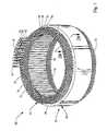
- FIG. 2Ais a perspective view of the stator core depicted in FIG. 1
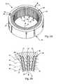
- FIG.2Bis a cross-sectional view of the core depicted in FIG. 2A ;
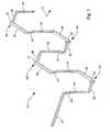
- FIG. 3is a perspective view of an individual conductor forming the stator winding
- FIG. 4is a perspective view of three conductors separated into phases
- FIG. 5is a perspective view of two conductors forming a bi-filar relationship
- FIG. 6is a perspective view of six conductors separated into three phases and two filars
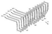
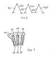
- FIG. 7is a perspective view of the complete stator winding partially depicted in FIG. 6 ;
- FIG. 8is a schematic depiction of the leads of the conductors depicted in FIGS. 6 and 7 ;
- FIG. 9is a cross-sectional view of the core similar to FIG. 2 a , but showing the conductors removed.
- FIG. 1depicts a perspective view of the stator 20 constructed in accordance with the teachings of the present invention.
- the stator 20generally comprises a stator core 22 and a stator winding 24 .
- a unique stator winding 24is employed to improve the cooling of the winding without increasing its size.
- the winding 24 and each of its conductorsmust be effectively cooled. It is also desirable to lower the temperature of the insulation on the conductors to prolong the life of the insulation and consequently the alternator.
- each conductoris directly related to the surface area of the conductor. To reduce the temperature rise, it is desirable to increase the surface area of the conductors to increase their convective cooling.
- the cross-sectional surface areaequals 2b+2h.
- the term rectangular or squaremay in fact include radii on the comers of the conductor. However, if this conductor is split in half across its width, the cross-sectional surface area equals 2(2b+(2 ⁇ 1 ⁇ 2h)) or 4b+2h.
- the stator winding 24is constructed to utilize a greater number of conductors having a smaller average cross sectional area, which are wound around the stator core 22 in a unique fashion that improves the efficiency of the alternator.
- the stator core 22is best seen In FIG. 2 a , and generally includes a cylindrical body 26 defining a plurality of slots 28 for receiving the stator winding 24 .
- the slots 28are equidistantly and circumferentially spaced around the cylindrical body 26 .
- the slots 28extend axially through the body 26 , from a first axial side 30 to a second axial side (not shown).
- the slots 28also open radially inwardly to the interior of the stator core 22 .
- the radial inward directionhas been generally indicated by arrow 15 .
- the stator winding 24is generally comprised of a plurality of conductors 32 which are wound around the stator core 22 by way of the plurality of slots 28 .
- Each conductorincludes a starting and ending lead 42 which are utilized to provide electrical connection of the stator winding 24 to the rectifier to form a ring (commonly known as a delta type for a three phase) or star (commonly known as a wye type for a three phase) configuration.
- ringcommonly known as a delta type for a three phase
- starcommonly known as a wye type for a three phase
- the plurality of phasesmay be connected to each other in a plurality of ring or star combinations.
- an individual conductor 32generally comprises a wire having a number of segments.
- a lead segment 42is utilized for electrical connection of the conductor 32 as described above.
- the remainder of the conductor 32generally comprises a plurality of straight segments 44 interconnecting a plurality of end loop segments 46 .
- the straight segments 44represent the portion of the conductor 32 which extends through the stator core 22 and resides in the core slots 28 .
- the end loops 46extend axially outwardly from the cylindrical body 26 of the stator core 22 , as is shown in FIG. 1 .
- the end loops 46alternate between the axial sides of the stator 20 .
- each end loop segment 46generally comprises a first leg 48 , and a second leg 50 meeting at an apex of the end loop 46 .
- the first leg 48extends away from a slot at an angle, which can be described as extending axially away from the core while extending clockwise circumferentially.
- the second leg 50extends away from a slot at an angle, which can be described as extending axially away from the core while extending counterclockwise circumferentially.
- the two legsmeet at the apex of the loop 46 , thereby forming an inverted triangle.
- one leg, 48 or 50may only extend axially away form the core while the other leg extends axially away from the core and circumferentially.
- a radial extension 52is defined and interconnects the first and second legs 48 , 50 .
- the second leg 50 of the end loop segment 46is interconnected with the second straight segment 44 via a second radial extension 54 .
- the first radial extension 52shifts the conductor radially outwardly (the radial Inward direction is indicated by arrow 15 ), while the second radial extension 54 shifts the conductor radially inwardly. It can thus be seen that each straight segment 44 of a conductor generally resides in the same radial position within the stator slot 28 , thereby forming a cascaded construction.
- the present inventionmay also employ an interlaced construction, wherein the second radial extension 54 is eliminated and thus it can be realized that consecutive straight segments 44 reside in alternating radial positions within the stator slots 28 . Therefore, although both cascaded and interlaced constructions include a set of straight segments 44 located equidistant radial positions in the stator slots 28 , only the cascade construction includes a plurality of consecutive straight segments 44 located in equidistant radial positions or in the same layer, as described further herein.
- the conductors 32are structured and organized in several different ways. First, the conductors can be characterized by what layer or layers their straight segments 44 reside in. With reference to FIGS. 1 and 2 b , the body 26 of the stator core 22 defines slots 28 which receive the straight segments 44 of the conductors 32 , as previously discussed. The conductors 32 can be characterized by what layer they reside in, which refers to the radial position of the conductor's straight segments 44 within the slot 28 . As shown in FIG. 2 b , the slots 28 receive conductors 32 at a first layer 34 , a second layer 36 , a third layer 38 and a fourth layer 40 , as denoted by the dotted lines. As also can be seen in FIG.
- the conductors 32may be aligned in one radial row within the slots 28 and may have widths that fit closely, including any insulation, to the width of the slots 28 . It can thus be seen that corresponding binding radial positions in each of the slots 28 define the layers 34 - 40 . Stated another way, the straight segments of the conductors 32 of all of the phases in the outer most radial position define the first layer 34 , and so on as the straight segments 44 of the conductors 32 fill radially inward positions. Preferably the straight segments of the conductors 32 reside in a common layer for each substantial revolution around the stator core. Furthermore, the conductor 32 may be continuous in that it may include a plurality of consecutive straight segments that reside in layer 34 for one substantial revolution, and a plurality of consecutive straight segments that reside in another layer, such as 38 , for another substantial revolution and so forth.
- each conductorwill have straight segments residing in multiple layers, i.e. a first layer during the first turn, a second layer during the second turn, etc.
- each conductor 32allows the stator winding 24 to be organized into phases, as will be described with reference to FIG. 4 .
- the first and second radial extensions 52 , 54allow a number of conductors 32 to be positioned in a cascading structure having multiple phases. Three phases have been depicted in FIG. 4 , defined by a first conductor 32 1 , a second conductor 32 2 , and a third conductor 32 3 . Although three phases have been depicted in FIG. 4 , FIG. 6 and FIG. 7 , it is commonly understood by those skilled in the art that any number of phases can be utilized.
- Each of the conductors 32 1 , 32 2 , 32 3are substantially identical, except they have been spaced a circumferential pitch or distance denoted by arrow 16 . Accordingly, only the first conductor 32 1 includes detailed reference numerals as the other conductors 32 2 and 32 3 are substantially identical. It can also be seen that the first and second radial extensions 52 , 54 located proximate the end loop segments 46 allow the three end loop segments 46 to overlap, while also maintaining each straight segment 44 in a single layer denoted as layer 34 . Each of the three phases is electrically connected by way of a ring (delta) connection or star (wye) connection, as is well known in the art, for providing current to the vehicle.
- the structure and phasing of the conductors 32provides fixed spacing to define air flow paths between the conductors, and more specifically between the end loop segments 46 .
- This structure of the stator winding 24can be referred to as a cascaded structure, however the plurality of conductors 32 could also form an interlaced structure wherein the straight segments 44 reside in alternating layers to define an interweaved pattern.
- a multiple filar constructionis employed, such as a bi-filar, tri-filar, etc.
- a multiple filar constructionis defined as a set of conductors electrically connected.
- a bi-filar constructionis depicted in FIG. 5.
- a first conductor 32 a and a second conductor 32 bare depicted and are electrically connected (FIG. 8 ).
- the two conductors 32 a , 32 bare prepared to sit within the stator core 22 in a fashion whereby the straight segments 44 a , 44 b reside in common slots 28 (i.e. aligned circumferential positions).
- the end loops 46 a , 46 b of the filarsare located axially opposite the other filar. That is, the end loops 46 a of the first filar are generally located directly axially opposite the end loops 46 b of the second filar. In this way, the correct frequency and phase of the current induced in each conductor 32 a , 32 b are aligned such that they are additive, and thus do not cancel each other out by way of their parallel electrical connection. It can also be seen that the straight segments 44 a of conductor 32 a all reside in layer 30 , while the straight segments 44 b of the other conductor 32 b reside in layer 34 .
- FIG. 6a combination of the layering, phasing, and multiple filar construction has been depicted.
- the portion of the stator winding 24 depicted in FIG. 6has a bi-filar construction. That is, there are two filars (a and b) for each phase ( 1 , 2 and 3 ).
- the conductorsare phased, as denoted by the circumferential pitch between each of the conductors 32 a 1 , 32 a 2 , 32 a 3 , 32 b 1 , 32 b 2 , 32 b 3 . It can be seen that corresponding filars in each of the phases have straight segments 44 which reside in common slots 28 .
- straight segment 44 a 1 and straight segment 44 b 1will reside in the same slot 28 .
- straight segment 44 a 2will reside in a common slot 28 with straight segment 44 b 2 .
- straight segments 44 a 3 and 44 b 3the portion of the stator winding 24 depicted in FIG. 6 has a three phase and bi-filar construction.
- each conductor 32is formed by the inverted triangle shape that has been described above.
- the inverted triangle shapealong with the phasing and the cascade or interlaced design forms the structure that provides fixed spacing to define air flow paths between the conductors, and more specifically between the end loop segments 46 .
- a complete stator winding 24has been shown in FIG. 7 , but has been cut at one point and unraveled for depiction as a straight member.
- the stator winding 24has a bi-filar construction as previously discussed, and denoted by conductors 32 a 1 , 32 a 2 , 32 a 3 forming a first filar, and the conductors 32 b 1 , 32 b 2 , 32 b 3 defining the second filar. Following each of these conductors towards the cut end denoted by numeral 60 , the conductors 32 continue from the opposing cut end 62 back towards the leads 42 . When each conductor 32 has made one complete turn (i.e.
- the conductor 32includes an extra radial extension (not shown) which shifts the conductor over two layers for forming a second turn or revolution.
- first conductor 32 a 1includes straight segments which reside in the second layer 36 throughout its first turn. Then, conductor 32 a 1 shifts over to the fourth layer 40 and completes a second turn. The conductor 32 a 1 would then end with a terminating lead 42 as shown.
- the stator winding 24 depicted in FIG. 7represents a two turn, three phase, bi-filar construction. Additionally, the stator winding 24 includes six conductors and resides in four layers. Current high slot fill stator designs typically employ conductors having four electrical turns and four layers. However, by way of the present invention, a stator 20 can be formed with a stator winding 24 having four electrical turns and eight layers. Preferably, the number of layers is greater than six.
- the multiple filar constructionallows small conductors to fill the same winding space as would be filled by the larger conductors, without increasing the number of electrical turns which increases the impedance and resistance of the winding. That is, two conductors electrically connected in parallel take up the same volume as would a larger conductor, but provide more surface area for convective cooling through the fixed spacing provided by the structure of the winding, of each conductor 32 and the stator winding 24 .
- a bi-filar construction of the conductors 32will have a smaller radial depth or width of a corresponding monofilar conductor, and therefore is not as stiff and will ease insertion into the slots 28 of the stator core 22 .
- a less stiff wirewill also minimize the force on paper insulation 29 ( FIG. 9 ) positioned between the conductors 32 and the core 22 which will allow the use of thinner insulation paper such as less than 0.0045 inches. This will not only reduce cost, but it will also improve the slot fill factor.
- the radial ticks defined by radial extensions 52 proximate a portion of the and loops 46 of each conductor 32 in the outermost layer 34extend radially beyond the radial position of the straight segments of the outermost layer 34 by approximately the radial width of one wire.
- the radial extensions 52will not kick out as lar radially as the wires are now smaller in radial width. This will minimize the potential interference between the end loops 46 of the stator winding 24 from interfering with the housing that surrounds the stator. It will also allow the housing to fit closer to the stator winding 24 and therefore be smaller in diameter size which wil improve the power density, defined as output divided by alternator volume, of the alternator.
Landscapes
- Engineering & Computer Science (AREA)
- Power Engineering (AREA)
- Windings For Motors And Generators (AREA)
Abstract
Description
Claims (28)
Priority Applications (6)
| Application Number | Priority Date | Filing Date | Title |
|---|---|---|---|
| US10/723,527US6930426B2 (en) | 2003-11-26 | 2003-11-26 | Alternator stator having a multiple filar construction to improve convective cooling |
| US10/850,012US7129612B2 (en) | 2002-01-24 | 2004-05-19 | Stator assembly with cascaded winding and method of making same |
| FR0412202AFR2862818A1 (en) | 2003-11-26 | 2004-11-17 | Stator for dynamoelectric machine e.g. electrical alternator, has stator winding including conductors that define air flow paths that extend via loop segments, between phases of segments, as well as between layers of segments |
| DE102004056811ADE102004056811A1 (en) | 2003-11-26 | 2004-11-24 | Stator for an alternator with a multiple winding layer design (multifilar) to improve convective cooling |
| JP2004340714AJP4105144B2 (en) | 2003-11-26 | 2004-11-25 | Stator assembly for alternator |
| US11/536,708US7679253B2 (en) | 2002-01-24 | 2006-09-29 | Stator assembly with cascaded winding and method of making same |
Applications Claiming Priority (1)
| Application Number | Priority Date | Filing Date | Title |
|---|---|---|---|
| US10/723,527US6930426B2 (en) | 2003-11-26 | 2003-11-26 | Alternator stator having a multiple filar construction to improve convective cooling |
Related Parent Applications (1)
| Application Number | Title | Priority Date | Filing Date |
|---|---|---|---|
| US10/265,529Continuation-In-PartUS6759779B2 (en) | 2002-01-24 | 2002-10-07 | Automotive alternator stator assembly with rectangular continuous wire |
Related Child Applications (3)
| Application Number | Title | Priority Date | Filing Date |
|---|---|---|---|
| US10/324,319Continuation-In-PartUS6787961B2 (en) | 2002-01-24 | 2002-12-19 | Automotive alternator stator assembly with varying end loop height between layers |
| US10/850,012Continuation-In-PartUS7129612B2 (en) | 2002-01-24 | 2004-05-19 | Stator assembly with cascaded winding and method of making same |
| US11/536,708Continuation-In-PartUS7679253B2 (en) | 2002-01-24 | 2006-09-29 | Stator assembly with cascaded winding and method of making same |
Publications (2)
| Publication Number | Publication Date |
|---|---|
| US20050110360A1 US20050110360A1 (en) | 2005-05-26 |
| US6930426B2true US6930426B2 (en) | 2005-08-16 |
Family
ID=34552753
Family Applications (1)
| Application Number | Title | Priority Date | Filing Date |
|---|---|---|---|
| US10/723,527Expired - LifetimeUS6930426B2 (en) | 2002-01-24 | 2003-11-26 | Alternator stator having a multiple filar construction to improve convective cooling |
Country Status (4)
| Country | Link |
|---|---|
| US (1) | US6930426B2 (en) |
| JP (1) | JP4105144B2 (en) |
| DE (1) | DE102004056811A1 (en) |
| FR (1) | FR2862818A1 (en) |
Cited By (8)
| Publication number | Priority date | Publication date | Assignee | Title |
|---|---|---|---|---|
| US20060032044A1 (en)* | 2004-07-21 | 2006-02-16 | Visteon Global Technologies, Inc. | Method of forming cascaded stator winding |
| US20070273237A1 (en)* | 2006-05-25 | 2007-11-29 | Denso Corporation | Alternator having stator wound with wiring |
| US20080079328A1 (en)* | 2006-10-03 | 2008-04-03 | Denso Corporation | AC electric rotating machine with multiphase stator coils |
| US20100139082A1 (en)* | 2009-11-18 | 2010-06-10 | Remy Technologies, L.L.C. | Method and apparatus for loading stator windings into a stator core |
| US20100148620A1 (en)* | 2008-12-15 | 2010-06-17 | Denso Corportion | Stator for electric rotating machine |
| US20110227445A1 (en)* | 2008-11-13 | 2011-09-22 | Toyota Jidosha Kabushiki Kaisha | Stator and coil |
| US20120007462A1 (en)* | 2007-03-05 | 2012-01-12 | Denso Corporation | Stator for rotary electric machine and rotary electric machine using same |
| US9467010B2 (en) | 2011-11-17 | 2016-10-11 | Remy Technologies, L.L.C. | Method of winding a stator core with a continuous conductor having a rectangular cross-section and a stator core |
Families Citing this family (15)
| Publication number | Priority date | Publication date | Assignee | Title |
|---|---|---|---|---|
| JP5163278B2 (en)* | 2007-05-30 | 2013-03-13 | 株式会社デンソー | Rotating electric machine stator |
| FR2918815A1 (en)* | 2007-07-11 | 2009-01-16 | Valeo Equip Electr Moteur | POLYPHASE STATOR FOR INTERNAL VENTILATION ROTATING ELECTRIC MACHINE AND ROTATING ELECTRIC MACHINE COMPRISING SUCH A STATOR. |
| JP5812145B2 (en)* | 2008-12-15 | 2015-11-11 | 株式会社デンソー | Rotating electric machine stator |
| JP2010166802A (en)* | 2008-12-15 | 2010-07-29 | Denso Corp | Stator for rotating electrical machine |
| JP5195403B2 (en)* | 2008-12-25 | 2013-05-08 | トヨタ自動車株式会社 | Stator and coil cage |
| CN102668333A (en)* | 2010-02-18 | 2012-09-12 | 爱信艾达株式会社 | Armature for rotating electrical machine |
| US9641036B2 (en)* | 2012-08-31 | 2017-05-02 | Mitsubishi Electric Corporation | Rotary electric machine |
| JP6241332B2 (en)* | 2014-03-12 | 2017-12-06 | 株式会社デンソー | Stator winding, stator winding manufacturing method, stator, rotating electric machine and wheel |
| CN105634169B (en)* | 2016-01-19 | 2017-10-13 | 锦州汉拿电机有限公司 | Three-phase multiple-grooved flat type copper wire generator stator of vehicle assembly |
| DE112017002040T5 (en) | 2016-04-15 | 2019-01-03 | Borgwarner Inc. | Common sheet metal component for accommodating multiple line geometries in an electrical machine |
| CN111989845B (en)* | 2018-02-28 | 2023-06-02 | 格鲁博-工厂有限及两合公司 | Winding pad and coil pad comprising said winding pad, and component formed thereby of an electric machine, and method for manufacturing the same |
| CN110784047A (en)* | 2018-07-30 | 2020-02-11 | 福特全球技术公司 | Stator winding method and stator core winding |
| CN110289717B (en)* | 2018-12-04 | 2024-04-19 | 上海大学 | Permanent magnet motor stator multiphase winding |
| DE102020103165A1 (en)* | 2019-05-16 | 2020-11-19 | Schaeffler Technologies AG & Co. KG | Stator for an electrical machine with a ribbon-shaped winding unit for a stator winding and a method for its production |
| EP4462652A1 (en)* | 2023-05-09 | 2024-11-13 | Rolls-Royce Deutschland Ltd & Co KG | A stator for an electric machine and a corresponding method of assembling, an electrical machine including said stator and a method of operating thereof |
Citations (82)
| Publication number | Priority date | Publication date | Assignee | Title |
|---|---|---|---|---|
| US3566171A (en) | 1970-01-29 | 1971-02-23 | Gen Motors Corp | Main field coil for railway traction motor |
| US3634708A (en) | 1970-05-04 | 1972-01-11 | Ibm | Improved low inertia armature winding formed of a continuous wire |
| US3750273A (en) | 1971-11-18 | 1973-08-07 | Gen Electric | Method of making flexible loop, hard slot coils for dynamoelectric machine windings |
| US3809936A (en) | 1972-05-18 | 1974-05-07 | E Klein | Brushless generator |
| US3824683A (en) | 1973-08-13 | 1974-07-23 | Gen Electric | Method for reducing corona in a dynamoelectric machine |
| US4115915A (en) | 1975-07-31 | 1978-09-26 | General Electric Company | Process for manufacturing motor having windings constructed for automated assembly |
| US4260924A (en) | 1978-09-27 | 1981-04-07 | Westinghouse Electric Corp. | Conductor bar for dynamoelectric machines |
| US4307311A (en) | 1979-05-25 | 1981-12-22 | Robert Bosch Gmbh | Winding method for an electrical generator and generator manufactured by the method |
| US4329764A (en) | 1978-11-22 | 1982-05-18 | Mitsubishi Denki Kabushiki Kaisha | Stepped combination apparatus |
| US4331896A (en) | 1980-10-20 | 1982-05-25 | Sedgewick Richard D | Zig-zag windings, winding machine, and method |
| US4337567A (en) | 1978-09-27 | 1982-07-06 | Westinghouse Electric Corp. | Method of making a conductor bar for dynamoelectric machines |
| US4399843A (en) | 1980-10-20 | 1983-08-23 | Sedgewick Richard D | Zig-zag winding machine |
| US4405553A (en) | 1981-03-04 | 1983-09-20 | Asea Aktiebolag | Method of manufacturing a coil for an electrical machine |
| US4451749A (en) | 1981-09-11 | 1984-05-29 | Nippondenso Co., Ltd. | AC Generator |
| US4556811A (en) | 1980-01-10 | 1985-12-03 | Electric Indicator Company, Inc. | Coil unit and coil form for electrical machines |
| US4587824A (en) | 1985-05-22 | 1986-05-13 | Westinghouse Electric Corp. | Conductor bundle edge-bending tool for a dynamoelectric generator |
| US4617725A (en) | 1984-10-01 | 1986-10-21 | Siemens-Allis, Inc. | Method of making multiple-element strap winding for rotor pole |
| US4663551A (en) | 1983-05-02 | 1987-05-05 | Herbert Weh | Electrical machine |
| US4928042A (en) | 1986-03-22 | 1990-05-22 | Robert Bosch Gmbh | Circuit arrangement for operating a multi-phase synchronous motor on a direct-voltage system |
| US5115556A (en) | 1981-03-18 | 1992-05-26 | George Gavrilidis | Method of manufacturing windings for electromagnetic machines |
| US5343105A (en) | 1990-03-28 | 1994-08-30 | Mitsubishi Denki Kabushiki Kaisha | AC generator for vehicles |
| US5394321A (en) | 1992-09-02 | 1995-02-28 | Electric Power Research Institute, Inc. | Quasi square-wave back-EMF permanent magnet AC machines with five or more phases |
| US5444321A (en) | 1992-09-03 | 1995-08-22 | Hitachi, Ltd. | Induction alternating current generator and a generation method |
| US5449962A (en) | 1992-10-14 | 1995-09-12 | Nippondenso Co., Ltd. | Rotary electric machinery |
| US5519266A (en) | 1993-06-01 | 1996-05-21 | Anorad Corporation | High efficiency linear motor |
| US5539265A (en) | 1994-10-11 | 1996-07-23 | Ford Motor Company | Self-aligning rotor assembly |
| EP0751609A2 (en) | 1995-06-28 | 1997-01-02 | Mitsubishi Denki Kabushiki Kaisha | Vehicle-mounted alternator |
| US5722153A (en) | 1991-08-28 | 1998-03-03 | General Electric Company | Method for fabricating a split-loop armature coil for a motor |
| US5787567A (en) | 1995-02-17 | 1998-08-04 | Toyota Jidosha Kabushiki Kaisha | Coil-forming wire material and method of manufacturing such material |
| WO1999034499A1 (en) | 1997-12-23 | 1999-07-08 | Robert Bosch Gmbh | Method and device for producing wave windings for electrical machines |
| US5926940A (en) | 1996-08-14 | 1999-07-27 | Toyota Jidosha Kabushiki Kaisha | Manufacturing method for stator of motor |
| US5936326A (en) | 1997-05-26 | 1999-08-10 | Denso Corporation | Alternator for vehicle |
| US5955804A (en) | 1997-03-10 | 1999-09-21 | Denso Corporation | Alternator winding arrangement with coil ends spaced apart from one another for air passage |
| US5955810A (en) | 1997-05-26 | 1999-09-21 | Denso Corporation | Alternator for vehicle |
| US5962943A (en) | 1998-02-27 | 1999-10-05 | Sunstrand Corporation | Axial gap dynamoelectric machine |
| US5965965A (en) | 1997-05-26 | 1999-10-12 | Denso Corporation | Stator winding arrangement of alternator for vehicle |
| US5986375A (en) | 1997-09-26 | 1999-11-16 | Denso Corporation | Alternator for vehicle |
| US5994802A (en) | 1995-09-27 | 1999-11-30 | Denso Corporation | AC generator for vehicle |
| US5998903A (en) | 1997-05-26 | 1999-12-07 | Denso Corporation | Alternator for an automotive vehicle |
| US6011332A (en) | 1997-05-26 | 2000-01-04 | Denso Corporation | Stator cooling arrangement of alternator for vehicle |
| US6037695A (en) | 1994-03-23 | 2000-03-14 | Hitachi, Ltd. | Vehicle alternator having improved rotating yoke |
| US6059969A (en) | 1998-03-26 | 2000-05-09 | Denso Corporation | AC generator stator coil with noise reduction |
| US6078116A (en) | 1997-11-27 | 2000-06-20 | Denso Corporation | Alternator for vehicle |
| US6091169A (en) | 1997-09-26 | 2000-07-18 | Denso Corporation | Alternator for vehicle |
| US6097130A (en) | 1997-05-26 | 2000-08-01 | Denso Corporation | Alternator for vehicle |
| US6124660A (en) | 1997-05-26 | 2000-09-26 | Denso Corporation | AC generator for vehicles |
| US6137202A (en) | 1999-04-27 | 2000-10-24 | General Electric Company | Insulated coil and coiled frame and method for making same |
| US6137201A (en) | 1997-05-26 | 2000-10-24 | Denso Corporation | AC generator for vehicles |
| US6140735A (en)* | 1998-05-20 | 2000-10-31 | Denso Corporation | Rotary electric machine and method of manufacturing the same |
| US6147432A (en) | 1998-08-06 | 2000-11-14 | Denso Corporation | AC generator stator for vehicle |
| US6147430A (en) | 1998-05-25 | 2000-11-14 | Denso Corporation | Stator of AC generator for vehicle |
| US6177747B1 (en) | 1998-11-02 | 2001-01-23 | Denso Corporation | Vehicle AC generator and method of manufacturing the same |
| US6181043B1 (en) | 1997-12-10 | 2001-01-30 | Denso Corporation | Alternator for vehicle |
| US6201332B1 (en) | 1998-09-07 | 2001-03-13 | Denso Corporation | AC generator stator for vehicle |
| US6204586B1 (en) | 1998-11-25 | 2001-03-20 | Denso Corporation | Stator arrangement of vehicle AC generator |
| US6208060B1 (en) | 1998-05-25 | 2001-03-27 | Denso Corporation | Stator of vehicle AC generator and method of manufacturing the same |
| US6211594B1 (en) | 1998-11-26 | 2001-04-03 | Denso Corporation | Vehicle AC generator's stator |
| US6222295B1 (en) | 1998-10-09 | 2001-04-24 | Denso Corporation | Stator winding of vehicle AC generator |
| US6242836B1 (en) | 1998-06-26 | 2001-06-05 | Denso Corporation | Vehicle AC generators stator and method of manufacturing the same |
| US6252326B1 (en) | 1998-11-26 | 2001-06-26 | Denso Corporation | Stator of vehicle AC generator with circumferentially offset coil ends |
| US6268678B1 (en) | 2000-01-26 | 2001-07-31 | Mitsubishi Denki Kabushiki Kaisha | Alternator |
| US20010011852A1 (en) | 2000-02-03 | 2001-08-09 | Shigenobu Nakamura | Stator arrangement of rotary electric machine for vehicle |
| US6281614B1 (en) | 1997-08-01 | 2001-08-28 | Wolfgang Hill | Multiple phase electric machine with a space-optimized turn-to-turn winding |
| US6285105B1 (en) | 1999-12-06 | 2001-09-04 | Mitsubishi Denki Kabushiki Kaisha | Vehicular AC generator |
| US20010019234A1 (en) | 2000-02-07 | 2001-09-06 | Tsutomu Murakami | Coil assembly of rotating electrical machinery and method for producing the same, and stator of rotating electric machinery using the same coil assembly |
| US20010020807A1 (en) | 2000-03-13 | 2001-09-13 | Hideo Imori | Alternator, stator winding assembly therefor, and method of manufacture for the stator winding assembly |
| US6291918B1 (en) | 1997-05-26 | 2001-09-18 | Denso Corporation | Alternator for vehicle |
| US20010024071A1 (en) | 1999-12-20 | 2001-09-27 | Ko Yoshida | Rotary electric machine with stator elastic support structure |
| US20010026109A1 (en) | 2000-04-03 | 2001-10-04 | Kyoko Higashino | Stator for an alternator |
| US20010030487A1 (en) | 2000-04-14 | 2001-10-18 | Kyoko Higashino | Automotive alternator |
| US20010038251A1 (en) | 2000-04-27 | 2001-11-08 | Shigenobu Nakamura | Stator of rotary electric machine and method for making the same |
| US20010040416A1 (en) | 1999-12-09 | 2001-11-15 | Shigenobu Nakamura | Rotary electric machine for vehicle |
| US20010040418A1 (en) | 2000-02-29 | 2001-11-15 | Kyoko Higashino | Alternator |
| US20010040415A1 (en) | 1999-10-15 | 2001-11-15 | Yoshihito Asao | A.C. generator for vehicle |
| US6333573B1 (en) | 1999-07-12 | 2001-12-25 | Denso Corporation | Rotary electric machine having resin covered joined portions |
| US6335583B1 (en) | 1998-05-25 | 2002-01-01 | Denso Corporation | Stator of vehicle AC generator and method of manufacturing the same |
| US6337530B1 (en) | 1997-10-17 | 2002-01-08 | Denso Corporation | AC generator for vehicle with helical stator having bolt recesses on outer cylindrical surface |
| US6348751B1 (en) | 1997-12-12 | 2002-02-19 | New Generation Motors Corporation | Electric motor with active hysteresis-based control of winding currents and/or having an efficient stator winding arrangement and/or adjustable air gap |
| US6373164B1 (en)* | 2000-05-10 | 2002-04-16 | Mitsubishi Denki Kabushiki Kaisha | Stator for dynamo-electric machine |
| US20020063490A1 (en) | 2000-11-24 | 2002-05-30 | Yoshihito Asao | Automotive alternator |
| US6501205B1 (en)* | 1999-12-14 | 2002-12-31 | Mitsubishi Denki Kabushiki Kaisha | Alternator |
| US6552463B2 (en) | 2000-08-10 | 2003-04-22 | Mitsubishi Denki Kabushiki Kaisha | Dynamo-electric machine having winding phase groups of series-connected windings connected in parallel |
- 2003
- 2003-11-26USUS10/723,527patent/US6930426B2/ennot_activeExpired - Lifetime
- 2004
- 2004-11-17FRFR0412202Apatent/FR2862818A1/ennot_activeWithdrawn
- 2004-11-24DEDE102004056811Apatent/DE102004056811A1/ennot_activeWithdrawn
- 2004-11-25JPJP2004340714Apatent/JP4105144B2/ennot_activeExpired - Fee Related
Patent Citations (89)
| Publication number | Priority date | Publication date | Assignee | Title |
|---|---|---|---|---|
| US3566171A (en) | 1970-01-29 | 1971-02-23 | Gen Motors Corp | Main field coil for railway traction motor |
| US3634708A (en) | 1970-05-04 | 1972-01-11 | Ibm | Improved low inertia armature winding formed of a continuous wire |
| US3750273A (en) | 1971-11-18 | 1973-08-07 | Gen Electric | Method of making flexible loop, hard slot coils for dynamoelectric machine windings |
| US3809936A (en) | 1972-05-18 | 1974-05-07 | E Klein | Brushless generator |
| US3824683A (en) | 1973-08-13 | 1974-07-23 | Gen Electric | Method for reducing corona in a dynamoelectric machine |
| US4115915A (en) | 1975-07-31 | 1978-09-26 | General Electric Company | Process for manufacturing motor having windings constructed for automated assembly |
| US4260924A (en) | 1978-09-27 | 1981-04-07 | Westinghouse Electric Corp. | Conductor bar for dynamoelectric machines |
| US4337567A (en) | 1978-09-27 | 1982-07-06 | Westinghouse Electric Corp. | Method of making a conductor bar for dynamoelectric machines |
| US4329764A (en) | 1978-11-22 | 1982-05-18 | Mitsubishi Denki Kabushiki Kaisha | Stepped combination apparatus |
| US4307311A (en) | 1979-05-25 | 1981-12-22 | Robert Bosch Gmbh | Winding method for an electrical generator and generator manufactured by the method |
| US4556811A (en) | 1980-01-10 | 1985-12-03 | Electric Indicator Company, Inc. | Coil unit and coil form for electrical machines |
| US4331896A (en) | 1980-10-20 | 1982-05-25 | Sedgewick Richard D | Zig-zag windings, winding machine, and method |
| US4399843A (en) | 1980-10-20 | 1983-08-23 | Sedgewick Richard D | Zig-zag winding machine |
| US4405553A (en) | 1981-03-04 | 1983-09-20 | Asea Aktiebolag | Method of manufacturing a coil for an electrical machine |
| US5115556A (en) | 1981-03-18 | 1992-05-26 | George Gavrilidis | Method of manufacturing windings for electromagnetic machines |
| US4451749A (en) | 1981-09-11 | 1984-05-29 | Nippondenso Co., Ltd. | AC Generator |
| US4663551A (en) | 1983-05-02 | 1987-05-05 | Herbert Weh | Electrical machine |
| US4617725A (en) | 1984-10-01 | 1986-10-21 | Siemens-Allis, Inc. | Method of making multiple-element strap winding for rotor pole |
| US4587824A (en) | 1985-05-22 | 1986-05-13 | Westinghouse Electric Corp. | Conductor bundle edge-bending tool for a dynamoelectric generator |
| US4928042A (en) | 1986-03-22 | 1990-05-22 | Robert Bosch Gmbh | Circuit arrangement for operating a multi-phase synchronous motor on a direct-voltage system |
| US5343105A (en) | 1990-03-28 | 1994-08-30 | Mitsubishi Denki Kabushiki Kaisha | AC generator for vehicles |
| US5722153A (en) | 1991-08-28 | 1998-03-03 | General Electric Company | Method for fabricating a split-loop armature coil for a motor |
| US5394321A (en) | 1992-09-02 | 1995-02-28 | Electric Power Research Institute, Inc. | Quasi square-wave back-EMF permanent magnet AC machines with five or more phases |
| US5642009A (en) | 1992-09-02 | 1997-06-24 | Electric Power Research Institute, Inc. | Quasi square-wave back-EMF permanent magnet AC machines with five or more phases |
| US5444321A (en) | 1992-09-03 | 1995-08-22 | Hitachi, Ltd. | Induction alternating current generator and a generation method |
| US5449962A (en) | 1992-10-14 | 1995-09-12 | Nippondenso Co., Ltd. | Rotary electric machinery |
| US5519266A (en) | 1993-06-01 | 1996-05-21 | Anorad Corporation | High efficiency linear motor |
| US6037695A (en) | 1994-03-23 | 2000-03-14 | Hitachi, Ltd. | Vehicle alternator having improved rotating yoke |
| US5539265A (en) | 1994-10-11 | 1996-07-23 | Ford Motor Company | Self-aligning rotor assembly |
| US5787567A (en) | 1995-02-17 | 1998-08-04 | Toyota Jidosha Kabushiki Kaisha | Coil-forming wire material and method of manufacturing such material |
| EP0751609A2 (en) | 1995-06-28 | 1997-01-02 | Mitsubishi Denki Kabushiki Kaisha | Vehicle-mounted alternator |
| US5994802A (en) | 1995-09-27 | 1999-11-30 | Denso Corporation | AC generator for vehicle |
| US5926940A (en) | 1996-08-14 | 1999-07-27 | Toyota Jidosha Kabushiki Kaisha | Manufacturing method for stator of motor |
| US6166461A (en) | 1997-03-10 | 2000-12-26 | Denso Corporation | Winding arrangement of alternator for vehicle |
| US5955804A (en) | 1997-03-10 | 1999-09-21 | Denso Corporation | Alternator winding arrangement with coil ends spaced apart from one another for air passage |
| US6051906A (en) | 1997-05-26 | 2000-04-18 | Denso Corporation | Alternator for vehicle |
| US5936326A (en) | 1997-05-26 | 1999-08-10 | Denso Corporation | Alternator for vehicle |
| US6137201A (en) | 1997-05-26 | 2000-10-24 | Denso Corporation | AC generator for vehicles |
| US6291918B1 (en) | 1997-05-26 | 2001-09-18 | Denso Corporation | Alternator for vehicle |
| US5998903A (en) | 1997-05-26 | 1999-12-07 | Denso Corporation | Alternator for an automotive vehicle |
| US6011332A (en) | 1997-05-26 | 2000-01-04 | Denso Corporation | Stator cooling arrangement of alternator for vehicle |
| US5955810A (en) | 1997-05-26 | 1999-09-21 | Denso Corporation | Alternator for vehicle |
| US5965965A (en) | 1997-05-26 | 1999-10-12 | Denso Corporation | Stator winding arrangement of alternator for vehicle |
| US6181045B1 (en) | 1997-05-26 | 2001-01-30 | Denso Corporation | Alternator for vehicle |
| US6124660A (en) | 1997-05-26 | 2000-09-26 | Denso Corporation | AC generator for vehicles |
| US6097130A (en) | 1997-05-26 | 2000-08-01 | Denso Corporation | Alternator for vehicle |
| US6281614B1 (en) | 1997-08-01 | 2001-08-28 | Wolfgang Hill | Multiple phase electric machine with a space-optimized turn-to-turn winding |
| US6091169A (en) | 1997-09-26 | 2000-07-18 | Denso Corporation | Alternator for vehicle |
| US5986375A (en) | 1997-09-26 | 1999-11-16 | Denso Corporation | Alternator for vehicle |
| US6337530B1 (en) | 1997-10-17 | 2002-01-08 | Denso Corporation | AC generator for vehicle with helical stator having bolt recesses on outer cylindrical surface |
| US6078116A (en) | 1997-11-27 | 2000-06-20 | Denso Corporation | Alternator for vehicle |
| US6181043B1 (en) | 1997-12-10 | 2001-01-30 | Denso Corporation | Alternator for vehicle |
| US6348751B1 (en) | 1997-12-12 | 2002-02-19 | New Generation Motors Corporation | Electric motor with active hysteresis-based control of winding currents and/or having an efficient stator winding arrangement and/or adjustable air gap |
| WO1999034499A1 (en) | 1997-12-23 | 1999-07-08 | Robert Bosch Gmbh | Method and device for producing wave windings for electrical machines |
| US5962943A (en) | 1998-02-27 | 1999-10-05 | Sunstrand Corporation | Axial gap dynamoelectric machine |
| US6059969A (en) | 1998-03-26 | 2000-05-09 | Denso Corporation | AC generator stator coil with noise reduction |
| US6140735A (en)* | 1998-05-20 | 2000-10-31 | Denso Corporation | Rotary electric machine and method of manufacturing the same |
| US6208060B1 (en) | 1998-05-25 | 2001-03-27 | Denso Corporation | Stator of vehicle AC generator and method of manufacturing the same |
| US6147430A (en) | 1998-05-25 | 2000-11-14 | Denso Corporation | Stator of AC generator for vehicle |
| US6335583B1 (en) | 1998-05-25 | 2002-01-01 | Denso Corporation | Stator of vehicle AC generator and method of manufacturing the same |
| US6242836B1 (en) | 1998-06-26 | 2001-06-05 | Denso Corporation | Vehicle AC generators stator and method of manufacturing the same |
| US6147432A (en) | 1998-08-06 | 2000-11-14 | Denso Corporation | AC generator stator for vehicle |
| US6201332B1 (en) | 1998-09-07 | 2001-03-13 | Denso Corporation | AC generator stator for vehicle |
| US6222295B1 (en) | 1998-10-09 | 2001-04-24 | Denso Corporation | Stator winding of vehicle AC generator |
| US6177747B1 (en) | 1998-11-02 | 2001-01-23 | Denso Corporation | Vehicle AC generator and method of manufacturing the same |
| US6204586B1 (en) | 1998-11-25 | 2001-03-20 | Denso Corporation | Stator arrangement of vehicle AC generator |
| US6211594B1 (en) | 1998-11-26 | 2001-04-03 | Denso Corporation | Vehicle AC generator's stator |
| US6252326B1 (en) | 1998-11-26 | 2001-06-26 | Denso Corporation | Stator of vehicle AC generator with circumferentially offset coil ends |
| US6137202A (en) | 1999-04-27 | 2000-10-24 | General Electric Company | Insulated coil and coiled frame and method for making same |
| US6333573B1 (en) | 1999-07-12 | 2001-12-25 | Denso Corporation | Rotary electric machine having resin covered joined portions |
| US20010040415A1 (en) | 1999-10-15 | 2001-11-15 | Yoshihito Asao | A.C. generator for vehicle |
| US6285105B1 (en) | 1999-12-06 | 2001-09-04 | Mitsubishi Denki Kabushiki Kaisha | Vehicular AC generator |
| US20010040416A1 (en) | 1999-12-09 | 2001-11-15 | Shigenobu Nakamura | Rotary electric machine for vehicle |
| US6417592B2 (en) | 1999-12-09 | 2002-07-09 | Denso Corporation | Rotary electric machine for vehicle |
| US6501205B1 (en)* | 1999-12-14 | 2002-12-31 | Mitsubishi Denki Kabushiki Kaisha | Alternator |
| US20010024071A1 (en) | 1999-12-20 | 2001-09-27 | Ko Yoshida | Rotary electric machine with stator elastic support structure |
| US6268678B1 (en) | 2000-01-26 | 2001-07-31 | Mitsubishi Denki Kabushiki Kaisha | Alternator |
| US20010011852A1 (en) | 2000-02-03 | 2001-08-09 | Shigenobu Nakamura | Stator arrangement of rotary electric machine for vehicle |
| US20010019234A1 (en) | 2000-02-07 | 2001-09-06 | Tsutomu Murakami | Coil assembly of rotating electrical machinery and method for producing the same, and stator of rotating electric machinery using the same coil assembly |
| US20010040418A1 (en) | 2000-02-29 | 2001-11-15 | Kyoko Higashino | Alternator |
| US20010020807A1 (en) | 2000-03-13 | 2001-09-13 | Hideo Imori | Alternator, stator winding assembly therefor, and method of manufacture for the stator winding assembly |
| US20010026109A1 (en) | 2000-04-03 | 2001-10-04 | Kyoko Higashino | Stator for an alternator |
| US20010030487A1 (en) | 2000-04-14 | 2001-10-18 | Kyoko Higashino | Automotive alternator |
| US20010038251A1 (en) | 2000-04-27 | 2001-11-08 | Shigenobu Nakamura | Stator of rotary electric machine and method for making the same |
| US6373164B1 (en)* | 2000-05-10 | 2002-04-16 | Mitsubishi Denki Kabushiki Kaisha | Stator for dynamo-electric machine |
| US6552463B2 (en) | 2000-08-10 | 2003-04-22 | Mitsubishi Denki Kabushiki Kaisha | Dynamo-electric machine having winding phase groups of series-connected windings connected in parallel |
| EP1211781A1 (en) | 2000-11-24 | 2002-06-05 | Mitsubishi Denki Kabushiki Kaisha | Automotive alternator |
| US20020063490A1 (en) | 2000-11-24 | 2002-05-30 | Yoshihito Asao | Automotive alternator |
| US6515393B2 (en) | 2000-11-24 | 2003-02-04 | Mitsubishi Denki Kabushiki Kaisha | Automotive alternator |
Non-Patent Citations (1)
| Title |
|---|
| U.S. Appl. No. 10/324,319, filed Dec. 19, 2002. |
Cited By (16)
| Publication number | Priority date | Publication date | Assignee | Title |
|---|---|---|---|---|
| US7386931B2 (en)* | 2004-07-21 | 2008-06-17 | Visteon Global Technologies, Inc. | Method of forming cascaded stator winding |
| US20060032044A1 (en)* | 2004-07-21 | 2006-02-16 | Visteon Global Technologies, Inc. | Method of forming cascaded stator winding |
| US20070273237A1 (en)* | 2006-05-25 | 2007-11-29 | Denso Corporation | Alternator having stator wound with wiring |
| US20080079328A1 (en)* | 2006-10-03 | 2008-04-03 | Denso Corporation | AC electric rotating machine with multiphase stator coils |
| US7800273B2 (en) | 2006-10-03 | 2010-09-21 | Denso Corporation | AC electric rotating machine with multiphase stator coils |
| US8253296B2 (en)* | 2007-03-05 | 2012-08-28 | Denso Corporation | Stator for rotary electric machine and rotary electric machine using same |
| US20120007462A1 (en)* | 2007-03-05 | 2012-01-12 | Denso Corporation | Stator for rotary electric machine and rotary electric machine using same |
| US20110227445A1 (en)* | 2008-11-13 | 2011-09-22 | Toyota Jidosha Kabushiki Kaisha | Stator and coil |
| US8581467B2 (en)* | 2008-11-13 | 2013-11-12 | Toyota Jidosha Kabushiki Kaisha | Stator including a cage coil |
| US20100148620A1 (en)* | 2008-12-15 | 2010-06-17 | Denso Corportion | Stator for electric rotating machine |
| US8203247B2 (en)* | 2008-12-15 | 2012-06-19 | Denso Corporation | Stator for electric rotating machine |
| US20100139082A1 (en)* | 2009-11-18 | 2010-06-10 | Remy Technologies, L.L.C. | Method and apparatus for loading stator windings into a stator core |
| US8281481B2 (en) | 2009-11-18 | 2012-10-09 | Remy Technologies L.L.C. | Method for loading stator windings into a stator core |
| US8291577B2 (en) | 2009-11-18 | 2012-10-23 | Remy Technologies L.L.C. | Apparatus for loading stator windings into a stator core |
| US8096046B2 (en) | 2009-11-18 | 2012-01-17 | Remy Technologies L.L.C. | Apparatus for loading stator windings into a stator core |
| US9467010B2 (en) | 2011-11-17 | 2016-10-11 | Remy Technologies, L.L.C. | Method of winding a stator core with a continuous conductor having a rectangular cross-section and a stator core |
Also Published As
| Publication number | Publication date |
|---|---|
| JP4105144B2 (en) | 2008-06-25 |
| US20050110360A1 (en) | 2005-05-26 |
| DE102004056811A1 (en) | 2005-06-30 |
| FR2862818A1 (en) | 2005-05-27 |
| JP2005160297A (en) | 2005-06-16 |
Similar Documents
| Publication | Publication Date | Title |
|---|---|---|
| US6930426B2 (en) | Alternator stator having a multiple filar construction to improve convective cooling | |
| US6885124B2 (en) | Stator winding having radial aligned wraps | |
| US7005772B1 (en) | Stator winding having two slots per phase per pole | |
| US6787961B2 (en) | Automotive alternator stator assembly with varying end loop height between layers | |
| US6750581B2 (en) | Automotive alternator stator assembly with rectangular continuous wire | |
| US7365467B2 (en) | Low noise stator winding having a phase angle shift | |
| US7075206B1 (en) | Vehicle alternator stator winding having dual slot configuration | |
| US6862797B2 (en) | Automotive alternator stator assembly with rectangular continuous wire | |
| EP1365495A2 (en) | Automotive alternating-current dynamoelectric machine | |
| US7170211B2 (en) | Stator winding having transitions | |
| JP3858698B2 (en) | AC generator for vehicles | |
| US11605989B2 (en) | Stator winding with alternating winding pitches | |
| JP3593009B2 (en) | Rotating electric machine | |
| US20080185933A1 (en) | Three-phase rotating electrical machine | |
| US6366000B1 (en) | Alternator | |
| US6940202B1 (en) | Electrical machine having a stator winding with a plurality of filars | |
| US8981613B2 (en) | Electric rotating machine | |
| US7386931B2 (en) | Method of forming cascaded stator winding | |
| US6373166B1 (en) | Alternator | |
| JP6667634B2 (en) | Rotating electric machine | |
| US20220149687A1 (en) | Stator | |
| US20060152100A1 (en) | Vehicle alternator having reduced windings | |
| JPS63194555A (en) | Magnet generator |
Legal Events
| Date | Code | Title | Description |
|---|---|---|---|
| AS | Assignment | Owner name:VISTEON GLOBAL TECHNOLOGIES, INC., MICHIGAN Free format text:ASSIGNMENT OF ASSIGNORS INTEREST;ASSIGNORS:NEET, KIRK E.;HARPENAU, KEVIN ROY;REEL/FRAME:014755/0279 Effective date:20031125 | |
| STCF | Information on status: patent grant | Free format text:PATENTED CASE | |
| AS | Assignment | Owner name:JPMORGAN CHASE BANK, N.A., AS ADMINISTRATIVE AGENT Free format text:SECURITY AGREEMENT;ASSIGNOR:VISTEON GLOBAL TECHNOLOGIES, INC.;REEL/FRAME:020497/0733 Effective date:20060613 | |
| FPAY | Fee payment | Year of fee payment:4 | |
| AS | Assignment | Owner name:JPMORGAN CHASE BANK, TEXAS Free format text:SECURITY INTEREST;ASSIGNOR:VISTEON GLOBAL TECHNOLOGIES, INC.;REEL/FRAME:022368/0001 Effective date:20060814 Owner name:JPMORGAN CHASE BANK,TEXAS Free format text:SECURITY INTEREST;ASSIGNOR:VISTEON GLOBAL TECHNOLOGIES, INC.;REEL/FRAME:022368/0001 Effective date:20060814 | |
| AS | Assignment | Owner name:WILMINGTON TRUST FSB, AS ADMINISTRATIVE AGENT, MIN Free format text:ASSIGNMENT OF SECURITY INTEREST IN PATENTS;ASSIGNOR:JPMORGAN CHASE BANK, N.A., AS ADMINISTRATIVE AGENT;REEL/FRAME:022575/0186 Effective date:20090415 Owner name:WILMINGTON TRUST FSB, AS ADMINISTRATIVE AGENT,MINN Free format text:ASSIGNMENT OF SECURITY INTEREST IN PATENTS;ASSIGNOR:JPMORGAN CHASE BANK, N.A., AS ADMINISTRATIVE AGENT;REEL/FRAME:022575/0186 Effective date:20090415 | |
| AS | Assignment | Owner name:THE BANK OF NEW YORK MELLON, AS ADMINISTRATIVE AGE Free format text:ASSIGNMENT OF PATENT SECURITY INTEREST;ASSIGNOR:JPMORGAN CHASE BANK, N.A., A NATIONAL BANKING ASSOCIATION;REEL/FRAME:022974/0057 Effective date:20090715 | |
| AS | Assignment | Owner name:VISTEON GLOBAL TECHNOLOGIES, INC., MICHIGAN Free format text:RELEASE BY SECURED PARTY AGAINST SECURITY INTEREST IN PATENTS RECORDED AT REEL 022974 FRAME 0057;ASSIGNOR:THE BANK OF NEW YORK MELLON;REEL/FRAME:025095/0711 Effective date:20101001 | |
| AS | Assignment | Owner name:VISTEON GLOBAL TECHNOLOGIES, INC., MICHIGAN Free format text:RELEASE BY SECURED PARTY AGAINST SECURITY INTEREST IN PATENTS RECORDED AT REEL 022575 FRAME 0186;ASSIGNOR:WILMINGTON TRUST FSB, AS ADMINISTRATIVE AGENT;REEL/FRAME:025105/0201 Effective date:20101001 | |
| AS | Assignment | Owner name:MORGAN STANLEY SENIOR FUNDING, INC., AS AGENT, NEW Free format text:SECURITY AGREEMENT (REVOLVER);ASSIGNORS:VISTEON CORPORATION;VC AVIATION SERVICES, LLC;VISTEON ELECTRONICS CORPORATION;AND OTHERS;REEL/FRAME:025238/0298 Effective date:20101001 Owner name:MORGAN STANLEY SENIOR FUNDING, INC., AS AGENT, NEW Free format text:SECURITY AGREEMENT;ASSIGNORS:VISTEON CORPORATION;VC AVIATION SERVICES, LLC;VISTEON ELECTRONICS CORPORATION;AND OTHERS;REEL/FRAME:025241/0317 Effective date:20101007 | |
| AS | Assignment | Owner name:REMY TECHNOLOGIES, LLC, INDIANA Free format text:ASSIGNMENT OF ASSIGNORS INTEREST;ASSIGNOR:VISTEON GLOBAL TECHNOLOGIES, INC.;REEL/FRAME:025178/0028 Effective date:20101021 | |
| AS | Assignment | Owner name:BANK OF AMERICA, N.A., AS ADMINISTRATIVE AGENT, NO Free format text:GRANT OF PATENT SECURITY INTEREST;ASSIGNOR:REMY TECHNOLOGIES, L.L.C.;REEL/FRAME:025521/0387 Effective date:20101217 | |
| AS | Assignment | Owner name:WELLS FARGO CAPITAL FINANCE, LLC, AS AGENT, ILLINO Free format text:SECURITY AGREEMENT;ASSIGNORS:REMY TECHNOLOGIES, L.L.C.;REMY POWER PRODUCTS, LLC;REEL/FRAME:025525/0186 Effective date:20101217 | |
| AS | Assignment | Owner name:WESTERN REMAN INDUSTRIAL, INC., INDIANA Free format text:RELEASE OF SECURITY INTEREST IN INTELLECTUAL PROPERTY (SECOND LIEN);ASSIGNOR:BARCLAYS BANK PLC;REEL/FRAME:025577/0533 Effective date:20101217 Owner name:REMY ALTERNATORS, INC., INDIANA Free format text:RELEASE OF SECURITY INTEREST IN INTELLECTUAL PROPERTY (SECOND LIEN);ASSIGNOR:BARCLAYS BANK PLC;REEL/FRAME:025577/0533 Effective date:20101217 Owner name:POWER INVESTMENTS, INC., INDIANA Free format text:RELEASE OF SECURITY INTEREST IN INTELLECTUAL PROPERTY (SECOND LIEN);ASSIGNOR:BARCLAYS BANK PLC;REEL/FRAME:025577/0533 Effective date:20101217 Owner name:REMY SALES, INC., INDIANA Free format text:RELEASE OF SECURITY INTEREST IN INTELLECTUAL PROPERTY (SECOND LIEN);ASSIGNOR:BARCLAYS BANK PLC;REEL/FRAME:025577/0533 Effective date:20101217 Owner name:WORLD WIDE AUTOMOTIVE, L.L.C., INDIANA Free format text:RELEASE OF SECURITY INTEREST IN INTELLECTUAL PROPERTY (SECOND LIEN);ASSIGNOR:BARCLAYS BANK PLC;REEL/FRAME:025577/0533 Effective date:20101217 Owner name:REMY INTERNATIONAL HOLDINGS, INC., INDIANA Free format text:RELEASE OF SECURITY INTEREST IN INTELLECTUAL PROPERTY (SECOND LIEN);ASSIGNOR:BARCLAYS BANK PLC;REEL/FRAME:025577/0533 Effective date:20101217 Owner name:REMAN HOLDINGS, L.L.C., INDIANA Free format text:RELEASE OF SECURITY INTEREST IN INTELLECTUAL PROPERTY (SECOND LIEN);ASSIGNOR:BARCLAYS BANK PLC;REEL/FRAME:025577/0533 Effective date:20101217 Owner name:REMY INDIA HOLDINGS, INC., INDIANA Free format text:RELEASE OF SECURITY INTEREST IN INTELLECTUAL PROPERTY (SECOND LIEN);ASSIGNOR:BARCLAYS BANK PLC;REEL/FRAME:025577/0533 Effective date:20101217 Owner name:M & M. KNOPF AUTO PARTS, L.L.C., INDIANA Free format text:RELEASE OF SECURITY INTEREST IN INTELLECTUAL PROPERTY (SECOND LIEN);ASSIGNOR:BARCLAYS BANK PLC;REEL/FRAME:025577/0533 Effective date:20101217 Owner name:UNIT PARTS COMPANY, INDIANA Free format text:RELEASE OF SECURITY INTEREST IN INTELLECTUAL PROPERTY (SECOND LIEN);ASSIGNOR:BARCLAYS BANK PLC;REEL/FRAME:025577/0533 Effective date:20101217 Owner name:REMY INC., INDIANA Free format text:RELEASE OF SECURITY INTEREST IN INTELLECTUAL PROPERTY (SECOND LIEN);ASSIGNOR:BARCLAYS BANK PLC;REEL/FRAME:025577/0533 Effective date:20101217 Owner name:REMY REMAN, L.L.C., INDIANA Free format text:RELEASE OF SECURITY INTEREST IN INTELLECTUAL PROPERTY (SECOND LIEN);ASSIGNOR:BARCLAYS BANK PLC;REEL/FRAME:025577/0533 Effective date:20101217 Owner name:REMY KOREA HOLDINGS, L.L.C., INDIANA Free format text:RELEASE OF SECURITY INTEREST IN INTELLECTUAL PROPERTY (SECOND LIEN);ASSIGNOR:BARCLAYS BANK PLC;REEL/FRAME:025577/0533 Effective date:20101217 Owner name:REMY INTERNATIONAL, INC., INDIANA Free format text:RELEASE OF SECURITY INTEREST IN INTELLECTUAL PROPERTY (SECOND LIEN);ASSIGNOR:BARCLAYS BANK PLC;REEL/FRAME:025577/0533 Effective date:20101217 Owner name:PUBLITECH, INC., INDIANA Free format text:RELEASE OF SECURITY INTEREST IN INTELLECTUAL PROPERTY (SECOND LIEN);ASSIGNOR:BARCLAYS BANK PLC;REEL/FRAME:025577/0533 Effective date:20101217 | |
| AS | Assignment | Owner name:VC AVIATION SERVICES, LLC, MICHIGAN Free format text:RELEASE BY SECURED PARTY AGAINST SECURITY INTEREST IN PATENTS ON REEL 025241 FRAME 0317;ASSIGNOR:MORGAN STANLEY SENIOR FUNDING, INC.;REEL/FRAME:026178/0412 Effective date:20110406 Owner name:VISTEON GLOBAL TECHNOLOGIES, INC., MICHIGAN Free format text:RELEASE BY SECURED PARTY AGAINST SECURITY INTEREST IN PATENTS ON REEL 025241 FRAME 0317;ASSIGNOR:MORGAN STANLEY SENIOR FUNDING, INC.;REEL/FRAME:026178/0412 Effective date:20110406 Owner name:VISTEON INTERNATIONAL BUSINESS DEVELOPMENT, INC., Free format text:RELEASE BY SECURED PARTY AGAINST SECURITY INTEREST IN PATENTS ON REEL 025241 FRAME 0317;ASSIGNOR:MORGAN STANLEY SENIOR FUNDING, INC.;REEL/FRAME:026178/0412 Effective date:20110406 Owner name:VISTEON EUROPEAN HOLDING, INC., MICHIGAN Free format text:RELEASE BY SECURED PARTY AGAINST SECURITY INTEREST IN PATENTS ON REEL 025241 FRAME 0317;ASSIGNOR:MORGAN STANLEY SENIOR FUNDING, INC.;REEL/FRAME:026178/0412 Effective date:20110406 Owner name:VISTEON GLOBAL TREASURY, INC., MICHIGAN Free format text:RELEASE BY SECURED PARTY AGAINST SECURITY INTEREST IN PATENTS ON REEL 025241 FRAME 0317;ASSIGNOR:MORGAN STANLEY SENIOR FUNDING, INC.;REEL/FRAME:026178/0412 Effective date:20110406 Owner name:VISTEON ELECTRONICS CORPORATION, MICHIGAN Free format text:RELEASE BY SECURED PARTY AGAINST SECURITY INTEREST IN PATENTS ON REEL 025241 FRAME 0317;ASSIGNOR:MORGAN STANLEY SENIOR FUNDING, INC.;REEL/FRAME:026178/0412 Effective date:20110406 Owner name:VISTEON CORPORATION, MICHIGAN Free format text:RELEASE BY SECURED PARTY AGAINST SECURITY INTEREST IN PATENTS ON REEL 025241 FRAME 0317;ASSIGNOR:MORGAN STANLEY SENIOR FUNDING, INC.;REEL/FRAME:026178/0412 Effective date:20110406 Owner name:VISTEON SYSTEMS, LLC, MICHIGAN Free format text:RELEASE BY SECURED PARTY AGAINST SECURITY INTEREST IN PATENTS ON REEL 025241 FRAME 0317;ASSIGNOR:MORGAN STANLEY SENIOR FUNDING, INC.;REEL/FRAME:026178/0412 Effective date:20110406 Owner name:VISTEON INTERNATIONAL HOLDINGS, INC., MICHIGAN Free format text:RELEASE BY SECURED PARTY AGAINST SECURITY INTEREST IN PATENTS ON REEL 025241 FRAME 0317;ASSIGNOR:MORGAN STANLEY SENIOR FUNDING, INC.;REEL/FRAME:026178/0412 Effective date:20110406 | |
| FPAY | Fee payment | Year of fee payment:8 | |
| AS | Assignment | Owner name:VISTEON ELECTRONICS CORPORATION, MICHIGAN Free format text:RELEASE OF SECURITY INTEREST IN INTELLECTUAL PROPERTY;ASSIGNOR:MORGAN STANLEY SENIOR FUNDING, INC.;REEL/FRAME:033107/0717 Effective date:20140409 Owner name:VISTEON GLOBAL TREASURY, INC., MICHIGAN Free format text:RELEASE OF SECURITY INTEREST IN INTELLECTUAL PROPERTY;ASSIGNOR:MORGAN STANLEY SENIOR FUNDING, INC.;REEL/FRAME:033107/0717 Effective date:20140409 Owner name:VC AVIATION SERVICES, LLC, MICHIGAN Free format text:RELEASE OF SECURITY INTEREST IN INTELLECTUAL PROPERTY;ASSIGNOR:MORGAN STANLEY SENIOR FUNDING, INC.;REEL/FRAME:033107/0717 Effective date:20140409 Owner name:VISTEON INTERNATIONAL BUSINESS DEVELOPMENT, INC., Free format text:RELEASE OF SECURITY INTEREST IN INTELLECTUAL PROPERTY;ASSIGNOR:MORGAN STANLEY SENIOR FUNDING, INC.;REEL/FRAME:033107/0717 Effective date:20140409 Owner name:VISTEON INTERNATIONAL HOLDINGS, INC., MICHIGAN Free format text:RELEASE OF SECURITY INTEREST IN INTELLECTUAL PROPERTY;ASSIGNOR:MORGAN STANLEY SENIOR FUNDING, INC.;REEL/FRAME:033107/0717 Effective date:20140409 Owner name:VISTEON GLOBAL TECHNOLOGIES, INC., MICHIGAN Free format text:RELEASE OF SECURITY INTEREST IN INTELLECTUAL PROPERTY;ASSIGNOR:MORGAN STANLEY SENIOR FUNDING, INC.;REEL/FRAME:033107/0717 Effective date:20140409 Owner name:VISTEON SYSTEMS, LLC, MICHIGAN Free format text:RELEASE OF SECURITY INTEREST IN INTELLECTUAL PROPERTY;ASSIGNOR:MORGAN STANLEY SENIOR FUNDING, INC.;REEL/FRAME:033107/0717 Effective date:20140409 Owner name:VISTEON CORPORATION, MICHIGAN Free format text:RELEASE OF SECURITY INTEREST IN INTELLECTUAL PROPERTY;ASSIGNOR:MORGAN STANLEY SENIOR FUNDING, INC.;REEL/FRAME:033107/0717 Effective date:20140409 Owner name:VISTEON EUROPEAN HOLDINGS, INC., MICHIGAN Free format text:RELEASE OF SECURITY INTEREST IN INTELLECTUAL PROPERTY;ASSIGNOR:MORGAN STANLEY SENIOR FUNDING, INC.;REEL/FRAME:033107/0717 Effective date:20140409 | |
| AS | Assignment | Owner name:REMY TECHNOLOGIES, L.L.C., INDIANA Free format text:RELEASE OF SECURITY INTEREST IN PATENTS PREVIOUSLY RECORDED AT REEL/FRAME 025525/0186;ASSIGNOR:WELLS FARGO CAPITAL FINANCE, L.L.C.;REEL/FRAME:037108/0618 Effective date:20151110 Owner name:REMY POWER PRODUCTS, L.L.C., INDIANA Free format text:RELEASE OF SECURITY INTEREST IN PATENTS PREVIOUSLY RECORDED AT REEL/FRAME 025525/0186;ASSIGNOR:WELLS FARGO CAPITAL FINANCE, L.L.C.;REEL/FRAME:037108/0618 Effective date:20151110 Owner name:REMY TECHNOLOGIES, L.L.C., INDIANA Free format text:RELEASE OF SECURITY INTEREST IN PATENTS PREVIOUSLY RECORDED AT REEL/FRAME 025521/0387;ASSIGNOR:BANK OF AMERICA, N.A.;REEL/FRAME:037101/0125 Effective date:20151110 | |
| FPAY | Fee payment | Year of fee payment:12 | |
| AS | Assignment | Owner name:BORGWARNER INC., MICHIGAN Free format text:ASSIGNMENT OF ASSIGNORS INTEREST;ASSIGNOR:REMY TECHNOLOGIES, L.L.C.;REEL/FRAME:043539/0619 Effective date:20170811 |