US6929659B2 - Method of preventing the dislodgment of a stent-graft - Google Patents
Method of preventing the dislodgment of a stent-graftDownload PDFInfo
- Publication number
- US6929659B2 US6929659B2US10/082,920US8292002AUS6929659B2US 6929659 B2US6929659 B2US 6929659B2US 8292002 AUS8292002 AUS 8292002AUS 6929659 B2US6929659 B2US 6929659B2
- Authority
- US
- United States
- Prior art keywords
- stent
- graft
- dilation
- sutures
- grafts
- Prior art date
- Legal status (The legal status is an assumption and is not a legal conclusion. Google has not performed a legal analysis and makes no representation as to the accuracy of the status listed.)
- Expired - Fee Related, expires
Links
- 238000000034methodMethods0.000titleclaimsabstractdescription16
- 230000010339dilationEffects0.000claimsabstractdescription33
- 239000003356suture materialSubstances0.000claimsabstractdescription12
- 206010002329AneurysmDiseases0.000claimsdescription22
- 238000009966trimmingMethods0.000claimsdescription2
- 239000000463materialSubstances0.000abstractdescription32
- 239000004743PolypropyleneSubstances0.000abstractdescription5
- 238000009434installationMethods0.000abstractdescription5
- -1polypropylenePolymers0.000abstractdescription5
- 229920001155polypropylenePolymers0.000abstractdescription5
- 238000004904shorteningMethods0.000abstractdescription5
- 239000000853adhesiveSubstances0.000description8
- 230000001070adhesive effectEffects0.000description8
- 239000004744fabricSubstances0.000description6
- 239000000155meltSubstances0.000description6
- 229920000139polyethylene terephthalatePolymers0.000description5
- 210000004204blood vesselAnatomy0.000description4
- 230000008602contractionEffects0.000description3
- 238000002844meltingMethods0.000description3
- 230000008018meltingEffects0.000description3
- 210000000702aorta abdominalAnatomy0.000description2
- 210000001367arteryAnatomy0.000description2
- 230000008901benefitEffects0.000description2
- 239000008280bloodSubstances0.000description2
- 210000004369bloodAnatomy0.000description2
- 230000036772blood pressureEffects0.000description2
- 238000002513implantationMethods0.000description2
- 239000007921spraySubstances0.000description2
- 102000008186CollagenHuman genes0.000description1
- 108010035532CollagenProteins0.000description1
- 102000016942ElastinHuman genes0.000description1
- 108010014258ElastinProteins0.000description1
- 239000004677NylonSubstances0.000description1
- 239000004642PolyimideSubstances0.000description1
- 239000004809TeflonSubstances0.000description1
- 229920006362Teflon®Polymers0.000description1
- 206010060872Transplant failureDiseases0.000description1
- 238000004026adhesive bondingMethods0.000description1
- 239000000560biocompatible materialSubstances0.000description1
- 239000012620biological materialSubstances0.000description1
- 229920001436collagenPolymers0.000description1
- 230000006835compressionEffects0.000description1
- 238000007906compressionMethods0.000description1
- 238000002788crimpingMethods0.000description1
- 230000001419dependent effectEffects0.000description1
- 230000000916dilatatory effectEffects0.000description1
- 229920002549elastinPolymers0.000description1
- 238000002474experimental methodMethods0.000description1
- 239000012530fluidSubstances0.000description1
- 238000002594fluoroscopyMethods0.000description1
- 238000003780insertionMethods0.000description1
- 230000037431insertionEffects0.000description1
- 230000007246mechanismEffects0.000description1
- 238000012986modificationMethods0.000description1
- 230000004048modificationEffects0.000description1
- 235000015097nutrientsNutrition0.000description1
- 229920001778nylonPolymers0.000description1
- 210000000056organAnatomy0.000description1
- 229920001692polycarbonate urethanePolymers0.000description1
- 229920001721polyimidePolymers0.000description1
- 229920000098polyolefinPolymers0.000description1
- 229920001343polytetrafluoroethylenePolymers0.000description1
- 229920002635polyurethanePolymers0.000description1
- 239000004814polyurethaneSubstances0.000description1
- 229920002379silicone rubberPolymers0.000description1
- 239000004945silicone rubberSubstances0.000description1
- 239000007787solidSubstances0.000description1
- 229910001220stainless steelInorganic materials0.000description1
- 239000010935stainless steelSubstances0.000description1
- 229910052715tantalumInorganic materials0.000description1
- GUVRBAGPIYLISA-UHFFFAOYSA-Ntantalum atomChemical compound[Ta]GUVRBAGPIYLISA-UHFFFAOYSA-N0.000description1
- BFKJFAAPBSQJPD-UHFFFAOYSA-NtetrafluoroetheneChemical compoundFC(F)=C(F)FBFKJFAAPBSQJPD-UHFFFAOYSA-N0.000description1
- 238000003466weldingMethods0.000description1
Images


Classifications
- A—HUMAN NECESSITIES
- A61—MEDICAL OR VETERINARY SCIENCE; HYGIENE
- A61F—FILTERS IMPLANTABLE INTO BLOOD VESSELS; PROSTHESES; DEVICES PROVIDING PATENCY TO, OR PREVENTING COLLAPSING OF, TUBULAR STRUCTURES OF THE BODY, e.g. STENTS; ORTHOPAEDIC, NURSING OR CONTRACEPTIVE DEVICES; FOMENTATION; TREATMENT OR PROTECTION OF EYES OR EARS; BANDAGES, DRESSINGS OR ABSORBENT PADS; FIRST-AID KITS
- A61F2/00—Filters implantable into blood vessels; Prostheses, i.e. artificial substitutes or replacements for parts of the body; Appliances for connecting them with the body; Devices providing patency to, or preventing collapsing of, tubular structures of the body, e.g. stents
- A61F2/82—Devices providing patency to, or preventing collapsing of, tubular structures of the body, e.g. stents
- A61F2/86—Stents in a form characterised by the wire-like elements; Stents in the form characterised by a net-like or mesh-like structure
- A61F2/90—Stents in a form characterised by the wire-like elements; Stents in the form characterised by a net-like or mesh-like structure characterised by a net-like or mesh-like structure
- A—HUMAN NECESSITIES
- A61—MEDICAL OR VETERINARY SCIENCE; HYGIENE
- A61F—FILTERS IMPLANTABLE INTO BLOOD VESSELS; PROSTHESES; DEVICES PROVIDING PATENCY TO, OR PREVENTING COLLAPSING OF, TUBULAR STRUCTURES OF THE BODY, e.g. STENTS; ORTHOPAEDIC, NURSING OR CONTRACEPTIVE DEVICES; FOMENTATION; TREATMENT OR PROTECTION OF EYES OR EARS; BANDAGES, DRESSINGS OR ABSORBENT PADS; FIRST-AID KITS
- A61F2/00—Filters implantable into blood vessels; Prostheses, i.e. artificial substitutes or replacements for parts of the body; Appliances for connecting them with the body; Devices providing patency to, or preventing collapsing of, tubular structures of the body, e.g. stents
- A61F2/02—Prostheses implantable into the body
- A61F2/04—Hollow or tubular parts of organs, e.g. bladders, tracheae, bronchi or bile ducts
- A61F2/06—Blood vessels
- A61F2/07—Stent-grafts
- A—HUMAN NECESSITIES
- A61—MEDICAL OR VETERINARY SCIENCE; HYGIENE
- A61F—FILTERS IMPLANTABLE INTO BLOOD VESSELS; PROSTHESES; DEVICES PROVIDING PATENCY TO, OR PREVENTING COLLAPSING OF, TUBULAR STRUCTURES OF THE BODY, e.g. STENTS; ORTHOPAEDIC, NURSING OR CONTRACEPTIVE DEVICES; FOMENTATION; TREATMENT OR PROTECTION OF EYES OR EARS; BANDAGES, DRESSINGS OR ABSORBENT PADS; FIRST-AID KITS
- A61F2/00—Filters implantable into blood vessels; Prostheses, i.e. artificial substitutes or replacements for parts of the body; Appliances for connecting them with the body; Devices providing patency to, or preventing collapsing of, tubular structures of the body, e.g. stents
- A61F2/02—Prostheses implantable into the body
- A61F2/04—Hollow or tubular parts of organs, e.g. bladders, tracheae, bronchi or bile ducts
- A61F2/06—Blood vessels
- A61F2002/065—Y-shaped blood vessels
- A—HUMAN NECESSITIES
- A61—MEDICAL OR VETERINARY SCIENCE; HYGIENE
- A61F—FILTERS IMPLANTABLE INTO BLOOD VESSELS; PROSTHESES; DEVICES PROVIDING PATENCY TO, OR PREVENTING COLLAPSING OF, TUBULAR STRUCTURES OF THE BODY, e.g. STENTS; ORTHOPAEDIC, NURSING OR CONTRACEPTIVE DEVICES; FOMENTATION; TREATMENT OR PROTECTION OF EYES OR EARS; BANDAGES, DRESSINGS OR ABSORBENT PADS; FIRST-AID KITS
- A61F2/00—Filters implantable into blood vessels; Prostheses, i.e. artificial substitutes or replacements for parts of the body; Appliances for connecting them with the body; Devices providing patency to, or preventing collapsing of, tubular structures of the body, e.g. stents
- A61F2/02—Prostheses implantable into the body
- A61F2/04—Hollow or tubular parts of organs, e.g. bladders, tracheae, bronchi or bile ducts
- A61F2/06—Blood vessels
- A61F2/07—Stent-grafts
- A61F2002/072—Encapsulated stents, e.g. wire or whole stent embedded in lining
- A—HUMAN NECESSITIES
- A61—MEDICAL OR VETERINARY SCIENCE; HYGIENE
- A61F—FILTERS IMPLANTABLE INTO BLOOD VESSELS; PROSTHESES; DEVICES PROVIDING PATENCY TO, OR PREVENTING COLLAPSING OF, TUBULAR STRUCTURES OF THE BODY, e.g. STENTS; ORTHOPAEDIC, NURSING OR CONTRACEPTIVE DEVICES; FOMENTATION; TREATMENT OR PROTECTION OF EYES OR EARS; BANDAGES, DRESSINGS OR ABSORBENT PADS; FIRST-AID KITS
- A61F2/00—Filters implantable into blood vessels; Prostheses, i.e. artificial substitutes or replacements for parts of the body; Appliances for connecting them with the body; Devices providing patency to, or preventing collapsing of, tubular structures of the body, e.g. stents
- A61F2/02—Prostheses implantable into the body
- A61F2/04—Hollow or tubular parts of organs, e.g. bladders, tracheae, bronchi or bile ducts
- A61F2/06—Blood vessels
- A61F2/07—Stent-grafts
- A61F2002/075—Stent-grafts the stent being loosely attached to the graft material, e.g. by stitching
- A—HUMAN NECESSITIES
- A61—MEDICAL OR VETERINARY SCIENCE; HYGIENE
- A61F—FILTERS IMPLANTABLE INTO BLOOD VESSELS; PROSTHESES; DEVICES PROVIDING PATENCY TO, OR PREVENTING COLLAPSING OF, TUBULAR STRUCTURES OF THE BODY, e.g. STENTS; ORTHOPAEDIC, NURSING OR CONTRACEPTIVE DEVICES; FOMENTATION; TREATMENT OR PROTECTION OF EYES OR EARS; BANDAGES, DRESSINGS OR ABSORBENT PADS; FIRST-AID KITS
- A61F2220/00—Fixations or connections for prostheses classified in groups A61F2/00 - A61F2/26 or A61F2/82 or A61F9/00 or A61F11/00 or subgroups thereof
- A61F2220/0025—Connections or couplings between prosthetic parts, e.g. between modular parts; Connecting elements
- A61F2220/005—Connections or couplings between prosthetic parts, e.g. between modular parts; Connecting elements using adhesives
- A—HUMAN NECESSITIES
- A61—MEDICAL OR VETERINARY SCIENCE; HYGIENE
- A61F—FILTERS IMPLANTABLE INTO BLOOD VESSELS; PROSTHESES; DEVICES PROVIDING PATENCY TO, OR PREVENTING COLLAPSING OF, TUBULAR STRUCTURES OF THE BODY, e.g. STENTS; ORTHOPAEDIC, NURSING OR CONTRACEPTIVE DEVICES; FOMENTATION; TREATMENT OR PROTECTION OF EYES OR EARS; BANDAGES, DRESSINGS OR ABSORBENT PADS; FIRST-AID KITS
- A61F2220/00—Fixations or connections for prostheses classified in groups A61F2/00 - A61F2/26 or A61F2/82 or A61F9/00 or A61F11/00 or subgroups thereof
- A61F2220/0025—Connections or couplings between prosthetic parts, e.g. between modular parts; Connecting elements
- A61F2220/0066—Connections or couplings between prosthetic parts, e.g. between modular parts; Connecting elements stapled
- A—HUMAN NECESSITIES
- A61—MEDICAL OR VETERINARY SCIENCE; HYGIENE
- A61F—FILTERS IMPLANTABLE INTO BLOOD VESSELS; PROSTHESES; DEVICES PROVIDING PATENCY TO, OR PREVENTING COLLAPSING OF, TUBULAR STRUCTURES OF THE BODY, e.g. STENTS; ORTHOPAEDIC, NURSING OR CONTRACEPTIVE DEVICES; FOMENTATION; TREATMENT OR PROTECTION OF EYES OR EARS; BANDAGES, DRESSINGS OR ABSORBENT PADS; FIRST-AID KITS
- A61F2220/00—Fixations or connections for prostheses classified in groups A61F2/00 - A61F2/26 or A61F2/82 or A61F9/00 or A61F11/00 or subgroups thereof
- A61F2220/0025—Connections or couplings between prosthetic parts, e.g. between modular parts; Connecting elements
- A61F2220/0075—Connections or couplings between prosthetic parts, e.g. between modular parts; Connecting elements sutured, ligatured or stitched, retained or tied with a rope, string, thread, wire or cable
- A—HUMAN NECESSITIES
- A61—MEDICAL OR VETERINARY SCIENCE; HYGIENE
- A61F—FILTERS IMPLANTABLE INTO BLOOD VESSELS; PROSTHESES; DEVICES PROVIDING PATENCY TO, OR PREVENTING COLLAPSING OF, TUBULAR STRUCTURES OF THE BODY, e.g. STENTS; ORTHOPAEDIC, NURSING OR CONTRACEPTIVE DEVICES; FOMENTATION; TREATMENT OR PROTECTION OF EYES OR EARS; BANDAGES, DRESSINGS OR ABSORBENT PADS; FIRST-AID KITS
- A61F2230/00—Geometry of prostheses classified in groups A61F2/00 - A61F2/26 or A61F2/82 or A61F9/00 or A61F11/00 or subgroups thereof
- A61F2230/0063—Three-dimensional shapes
- A61F2230/0067—Three-dimensional shapes conical
- A—HUMAN NECESSITIES
- A61—MEDICAL OR VETERINARY SCIENCE; HYGIENE
- A61F—FILTERS IMPLANTABLE INTO BLOOD VESSELS; PROSTHESES; DEVICES PROVIDING PATENCY TO, OR PREVENTING COLLAPSING OF, TUBULAR STRUCTURES OF THE BODY, e.g. STENTS; ORTHOPAEDIC, NURSING OR CONTRACEPTIVE DEVICES; FOMENTATION; TREATMENT OR PROTECTION OF EYES OR EARS; BANDAGES, DRESSINGS OR ABSORBENT PADS; FIRST-AID KITS
- A61F2230/00—Geometry of prostheses classified in groups A61F2/00 - A61F2/26 or A61F2/82 or A61F9/00 or A61F11/00 or subgroups thereof
- A61F2230/0063—Three-dimensional shapes
- A61F2230/0073—Quadric-shaped
- A61F2230/0078—Quadric-shaped hyperboloidal
- A—HUMAN NECESSITIES
- A61—MEDICAL OR VETERINARY SCIENCE; HYGIENE
- A61F—FILTERS IMPLANTABLE INTO BLOOD VESSELS; PROSTHESES; DEVICES PROVIDING PATENCY TO, OR PREVENTING COLLAPSING OF, TUBULAR STRUCTURES OF THE BODY, e.g. STENTS; ORTHOPAEDIC, NURSING OR CONTRACEPTIVE DEVICES; FOMENTATION; TREATMENT OR PROTECTION OF EYES OR EARS; BANDAGES, DRESSINGS OR ABSORBENT PADS; FIRST-AID KITS
- A61F2250/00—Special features of prostheses classified in groups A61F2/00 - A61F2/26 or A61F2/82 or A61F9/00 or A61F11/00 or subgroups thereof
- A61F2250/0014—Special features of prostheses classified in groups A61F2/00 - A61F2/26 or A61F2/82 or A61F9/00 or A61F11/00 or subgroups thereof having different values of a given property or geometrical feature, e.g. mechanical property or material property, at different locations within the same prosthesis
- A61F2250/0039—Special features of prostheses classified in groups A61F2/00 - A61F2/26 or A61F2/82 or A61F9/00 or A61F11/00 or subgroups thereof having different values of a given property or geometrical feature, e.g. mechanical property or material property, at different locations within the same prosthesis differing in diameter
- Y—GENERAL TAGGING OF NEW TECHNOLOGICAL DEVELOPMENTS; GENERAL TAGGING OF CROSS-SECTIONAL TECHNOLOGIES SPANNING OVER SEVERAL SECTIONS OF THE IPC; TECHNICAL SUBJECTS COVERED BY FORMER USPC CROSS-REFERENCE ART COLLECTIONS [XRACs] AND DIGESTS
- Y10—TECHNICAL SUBJECTS COVERED BY FORMER USPC
- Y10S—TECHNICAL SUBJECTS COVERED BY FORMER USPC CROSS-REFERENCE ART COLLECTIONS [XRACs] AND DIGESTS
- Y10S623/00—Prosthesis, i.e. artificial body members, parts thereof, or aids and accessories therefor
- Y10S623/902—Method of implanting
- Y10S623/903—Blood vessel
Definitions
- the inventionrelates to implantable prostheses.
- the inventionrelates to endoluminal stent-grafts which are deployed in blood vessels to bridge aneurysms.
- the inventionis particularly related to a method for using stent-grafts which incorporate a structure for restricting dilation of the stent-graft after it is implanted.
- Transluminal prosthesesare well known in the medical arts for implantation in blood vessels, biliary ducts, or other similar organs of the living body. These prostheses are commonly known as stents and are used to maintain, open, or dilate tubular structures or to support tubular structures that are being anastomosed. When biocompatible materials are used as a covering or lining for the stent, the prosthesis is called a stent-graft. If used specifically in blood vessels, the stent-graft is known as an endovascular graft. A stent or stent-graft may be introduced into the body by stretching it longitudinally or compressing it radially, until its diameter is reduced sufficiently so that it can be fed into a catheter.
- the stent-graftis delivered through the catheter to the site of deployment. If the stent-graft is a self-expanding stent-graft, when it is released from the catheter, it self-expands. If the stent-graft is not self-expanding, upon release from the catheter it is mechanically expanded (e.g., by a balloon). Regardless of whether they are self-expanding or not, stent-grafts introduced in this manner are known as endoluminal stent-grants.
- FIGS. 1 , 1 a , 2 , and 2 aA typical state of the art self-expanding stent, such as disclosed in U.S. Pat. No. 4,655,771 to Wallsten or in U.K. Patent Number 1,205,743 to Didcott, is shown herein in prior art FIGS. 1 , 1 a , 2 , and 2 a .
- Didcott and Wallstendisclose a tubular body stent 10 composed of wire elements, e.g., 12 , 13 , each of which extends in a helical configuration with the centerline 14 of the stent 10 as a common axis.
- Half of the elements, e.g. 12are wound in one direction while the other half, e.g. 13 , are wound in an opposite direction.
- the diameter of the stentis changeable by axial movement of the ends 9 , 11 of the stent.
- the crossing elementsform a braid-like configuration and are arranged so that the diameter of the stent 10 is normally expanded as shown in FIGS. 1 and 1 a .
- the diametermay be contracted by pulling the ends 9 , 11 of the stent 10 away from each other as shown by arrows 16 , 18 in FIG. 2 .
- the diameter of the stent 10self-expands and draws the ends 9 , 11 of the stent closer to each other.
- the contraction to stretching ratio and radial pressure of stentscan usually be determined from basic braid equations.
- FIG. 3shows a state of the art stent-graft 20 which includes a braided mesh stent exoskeleton 22 and an inner biocompatible liner 24 .
- the stent shownis a Didcott-type stent with a crossing angle ⁇ 90°, one straight 26 and one flared end 28 .
- the liner (graft material)is polyethylene terepthalate (PET), polycarbonate urethane, or expanded polytetrafluroethylene (EPTFE) material which is attached to the stent by means of sutures or adhesives.
- PETpolyethylene terepthalate
- EPTFEexpanded polytetrafluroethylene
- the state of the art stent-graftsinclude stents which are made of various different materials and which include self-expanding as well as balloon expandable stents.
- the graft materials of the state of the art stent-graftsinclude polyurethane, silicone rubber, polypropylene, polyolefin, collagen, elastin, etc.
- the graft materialmay be non-woven, woven, spun, knitted, braided, expanded, etc.
- an “exoskeleton” stentcan be attached to the inside of an “exoskeleton” stent or to the outside of an “endoskeleton” stent by sutures, adhesives, co-braids, staples, etc.; or it can be attached within (i.e., both inside and outside) the skeleton if desired.
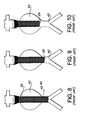
- the exemplary stent-graft 20 of FIG. 3is deployed with the aid of a catheter 30 and a guide wire 32 .
- the guide wire 32is maneuvered through blood vessels to a location in artery 34 beyond aneurysms 36 , 38 .
- the stent graft(not shown in FIG. 4 ) is carried inside the catheter 30 which is guided over the guide wire (with the aid of fluoroscopy) to the site of the aneurysms 36 , 38 .
- the stent-graftis deployed as shown in FIGS. 5-7 , by releasing one end 28 of the stent-graft 20 on one side of the aneurysms 36 , 38 .
- a pusher(not shown) which moves inside the catheter and pushes the stent-graft out of the catheter as the catheter is pulled back.
- the stent-graft 20expands as shown in the Figures and bridges the aneurysms 36 , 38 .
- the porous liner 24 of the stent-graft 20clots with blood and tissue ingrowth occurs.
- the linerthereby becomes non-porous or microporous allowing nutrient passage but no fluid leakage through the stent-graft into the aneurysms. It has been observed that, in many cases, after the graft has “healed-in,” the stent-graft begins to dilate as shorten.
- FIG. 8shows the stent-graft 20 installed in the abdominal aorta 40 bridging an aneurysm 42 .
- the stent-graft 20begins to heal-in.
- the stent-graft 20may begin to dilate and shorten as shown in FIG. 9 . This is particularly likely if the aneurysm 42 is empty rather than filled with organized clot.
- the dilation of the stent-graft 20will ultimately result in the end 26 of the stent-graft 20 slipping into the aneurysm 42 as shown in FIG. 10 .
- This dislocation of the stent-graftcan be catastrophic (even fatal) as it allows the aneurysm to be repressurized with blood, thereby risking rupture. While it is generally believed that a flared end of a stent-graft is more secure than a non-flared end, observations by the inventor suggest that this is not true. As shown in FIG. 11 , the flared end 28 of the stent-graft 20 can become dislodged and slip into the aneurysm 42 with the same catastrophic results.
- stent-graftsdilate and become dislodged over time. It is believed that the dilation is the result of blood pressure acting on the wall of the stent-graft. At a low crossing angle of the stent wires, e.g., 90°, pressure inside the stent-graft will cause a dilation and shortening of the stent-graft. At a higher crossing angle of the stent wires, e.g., 120°, the pressure inside the stent-graft causes a lengthening of the stent-graft, which can result in a dislodging of the stent-graft.
- Another object of the inventionis to provide an endoluminal stent-graft which is resistant to dilation but which is still expandable during installation.
- Still another object of the inventionis to provide an endoluminal stent-graft which is resistant to dilation but which is still self-expanding during installation.
- Still yet another object of the inventionis to provide a method of preventing the dislodgement of a stent-graft after deployment.
- the endoluminal stent-grafts of the present inventioninclude several features which restrict dilation subsequent to installation but which allow the stent-grafts to be installed in the same manner as a conventional stent-graft.
- a suture or a plurality of suturesare attached to an expanded conventional stent-graft.
- individual suturesare used to distribute the load of dilation restriction among many sutures and to allow the stent-graft to be trimmed to length at the operating table.
- the suturescan be placed on the outside or the inside of the stent-graft or sandwiched between the stent and the graft material.
- Various placement and attachment designs for the for the suturesare disclosed.
- the preferred embodimentsinclude attaching the sutures to the outside of the stent-graft or intertwining the sutures with the wires of the stent. If the stent is a helically wound stent, it is preferred that the crossing angle of the wires be obtuse when the stent is fully expanded. According to a preferred embodiment, the crossing angle of the wires is between 100° and 120° when the stent is expanded. This crossing angle prevents the stent-graft from shortening when it is dilated. More particularly, an angle of approximately 109.5° is most preferred in order to maximum the volume in the braided suture and prevent expansion or contraction.
- the suture materialis braided PET or polypropylene and sutures are interwoven into the stent at substantially regular intervals.
- the ends of each sutureare preferably knotted together and then melt cut.
- the stent and suture assemblyis then preferably spray coated with a melt adhesive, dried, and the graft liner is held against the melt adhesive while the assembly is heated to the melting point of the melt adhesive.
- the assemblyis then cooled.
- Alternate embodimentsinclude utilizing a band material in lieu of a suture material and utilizing a warp knit tubular sheath with inlay yarn in lieu of the sutures.
- the warp knit tubular sheath with inlay yarnalso acts as the graft material.
- FIG. 1is a broken side elevation view of a prior art braided stent expanded in a non-stressed position
- FIG. 1 ais an end view of FIG. 1 ;
- FIG. 2is a broken side elevation view of a prior art stent of FIGS. 1 and la stretched and contracted;
- FIG. 2 ais an end view of FIG. 2 ;
- FIG. 3is a schematic perspective view of a prior art stent graft
- FIG. 4is a schematic view of a prior art guide wire and deployment catheter near the site of an aneurysm
- FIG. 5is a view similar to FIG. 4 showing the prior art stent-graft in a first stage of deployment
- FIG. 6is a view similar to FIG. 5 showing the prior art stent-graft in a second stage of deployment
- FIG. 7is a view similar to FIG. 6 showing the prior art stent-graft deployed in an artery;
- FIG. 8is a schematic view of the prior art stent-graft deployed in the abdominal aorta
- FIG. 9is a view similar to FIG. 8 illustrating one end of the stent-graft partially dislodged
- FIG. 10is a view similar to FIG. 9 showing one end of the stent-graft completely dislodged;
- FIG. 11is a view similar to FIGS. 8-10 showing the other end of the stent-graft completely dislodged;
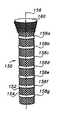
- FIG. 12is a schematic perspective view of a stent-graft according to the invention.
- FIG. 13is a schematic perspective view of a second embodiment of a stent-graft according to the invention.
- FIG. 14is a schematic perspective view of an illustrative simplified version of the second embodiment of a stent-graft according to the invention.
- FIG. 15is a schematic perspective view of the stent-graft of FIG. 14 under axial compression
- FIG. 16is a schematic illustration of a prior art warp knit fabric
- FIG. 17is a view similar to FIG. 16 showing the fabric stretched in one direction
- FIG. 18is a view similar to FIG. 16 showing the fabric stretched in another direction.
- the warp knit material used in the present inventionis a more complex warp knit with an asymmetrical inlay thread.
- the materialwill stretch in one direction but is restricted by the inlay thread from stretching in another direction.
- the sleeve of the inventionis manufactured with the material such that the stretchable axis is aligned with the longitudinal axis of the sleeve which is substantially collinear with the longitudinal axis of the stent-graft.
- a stent-graft 50includes a Walsten-type stent made up of wire elements, e.g. 52 , 54 , which are helically wound relative to the longitudinal axis 56 and braided relative to each other.
- the crossing angle ⁇ of the wiresis preferably between approximately 100° and approximately 120°, and more preferably approximately 109.5° when the stent is in the expanded state. This angle is chosen so that if the stent is dilated beyond the expanded state it will not contract in length.
- a plurality of suturese.g.
- the suture materialis braided PET or polypropylene, and sutures are interwoven into the stent at substantially regular intervals and in planes substantially perpendicular to the longitudinal axis of the stent. The ends of each suture are preferably knotted together and then melt cut.
- a conventional graft material 60may be attached to the interior of the stent in a conventional way.
- the stent and suture assemblyis spray coated with a melt adhesive, dried, and the graft liner 60 is held against the melt adhesive while the assembly is heated to the melting point of the melt adhesive. The assembly is then cooled.
- the stent-graftmay be deployed in a conventional manner and will exhibit significant resistance to dilation.
- a single suturemay be helically wound through the stent.
- a plurality of suturesis preferred because this allows the stent-graft to be trimmed to length at the operating table and because it spreads the load over many sutures.
- the suturesmay be interwoven with the stent wires, the sutures may be attached to the stent in other ways such as crimping, gluing, melting, welding, or twisting.
- the suturescan be attached to themselves or to a strut or wire and may be placed on the inside or the outside of the stent. According to preferred embodiments, the sutures are sandwiched between the stent and the graft material.
- suture materialis braided PET or polypropylene
- other suitable materialsinclude NYLON, TEFLON, polyimide, stainless steel or tantalum.
- the suture materialmay be monofilament or braided.
- one or more suturesmay be made of radiopaque material in order to locate the stent or a portion thereof; e.g., a bifurcated portion of the stent-graft.
- An important characteristic of the suturesis that they be flexible but substantially inelastic.
- sutures 58 a - 58 fare preferably sized to be the size of the desired expanded diameter of the stent-graft 50 .
- the suturesWhen the stent-graft is pulled down for insertion, the sutures will fold due to their flexibility; and when the stent-graft is released into its expanded state, the sutures will unfold to their maximum diameter. However, further dilation is resisted because the sutures are substantially inelastic.
- a second embodiment of a stent-graft 150includes a Didcott-type stent made up of wire elements, e.g. 152 , 154 , which are helically wound relative to the longitudinal axis 156 and braided relative to each other.
- the crossing angle of the wiresis preferably between approximately 100° and approximately 120° when the stent is in the expanded state.
- a conventional graft material 160may be attached to the interior of the stent in a conventional way.
- a plurality of bandse.g. 158 a - 158 f , are wrapped around the expanded stent and spaced apart from each other as shown.
- the bandswhich are preferably flat and wider than the sutures, can be braided, knitted, or woven and made of the same material as the sutures described above.
- the bandsare attached to the inside or the outside of the stent by any of the methods described above, including sandwiching the bands between the stent and the graft material 160 .
- the number and location of the bandsmay vary depending on the size and type of stent-graft.
- the bandscover between 5% and 30% of the surface area of the stent.
- FIGS. 14 and 15illustrate a simplified example of the stent 150 ′ having four centrally located bands 158 ′ a - 158 ′ d. If a compressive force is applied to the ends of the stent as indicated by the arrows in FIG. 15 , the bands will inhibit the stent from dilating.
- a third embodiment of a stent-graft according to the inventionincludes a Didcott-type stent made up of wire elements which are helically wound relative to the longitudinal axis and braided relative to each other.
- the crossing angle of the wiresis preferably between approximately 80° and approximately 100° when the stent is in the expanded state.
- a conventional graft materialmay be attached to the interior of the stent in a conventional way.
- a dilation restrictor sleeveis attached to the stent.
- the sleeveis made of a specially knit material and is attached to the sent in any of the manners described above with respect to sutures and bands. In order to appreciate the nature of the material used to fabricate the sleeve, it is useful to consider the nature of warp knit materials in general.
- a simple warp knit fabric 300is made of symmetrically knitted threads 302 (shown in solid) and 304 (shown in outline).
- the symmetrical arrangement of the threadsallows the fabric to stretch in two mutually orthogonal directions as shown in FIGS. 17 and 18 .
- the warp knit material used in the present inventionis a more complex warp knit with an asymmetrical inlay thread.
- the materialwill stretch in one direction but is restricted by the inlay thread from stretching in another direction.
- the sleeve of the inventionis manufactured with the material such that the stretchable axis is aligned with the longitudinal axis of the sleeve which is substantially collinear with the longitudinal axis of the stent-graft.
- the sleevewill allow the stent-graft to be easily “pulled down” for installation via a catheter and guide wire and will allow the stent-graft to expand to its determined diameter which restricts the stent-graft from dilation.
- the material used to make the sleevemay act as a substitute for the graft material.
- the warp knit patterncan be used to knit a fabric which is suitable for use as a graft material.
- the present inventionis particularly useful in view of the recognized problem of the stents and stent-grafts moving, or migrating, over time after initial placement. Because of this potential for dilation and subsequent dislodgment, the present invention includes a method for preventing the dislodgment of an endoluminal stent graft after deployment into an aneurysm. The method includes the steps of determining the length of the aneurysm into which the stent-graft will be placed and the resultant length of the particular stent-graft needed to bridge it. Because the degree of linear shortening of a stent during radial dilation is dependent upon its particular architecture, the doctor would correlate the maximum allowable diameter of the stent with the minimum length of that particular stent needed to bridge the aneurysm.
- a stent-graftis selected having dilation restriction means which prevent excessive dilation which could lead to catastrophic shortening of the stent-graft over time after initial placement. That suitably sized and appropriately restricted stent-graft is then cut to length and deployed in the aneurysm.
- a method of treating an aneurysm with a stent-graftcan be performed which involves determining the length of the aneurysm, determining the diameter of the vessel into which the stent-graft will be placed, providing a stent-graft having a dilation restriction means for restricting dilation of the stent-graft beyond a maximum diameter where the maximum diameter is greater than the vessel diameter of the vessel, and trimming the stent-graft to a length that is greater than the length of the aneurysm when the stent-graft is dilated to its maximum diameter.
- the dilation restriction meansmay compromise a suture material which may be flexible and inelastic.
- the stent-graftmay be made of woven wires and have the suture material woven through the wires.
- the dilation restriction meansmay comprise a plurality of sutures spaced along the expandable stent-graft.
- the plurality of suturesmay be located in a plurality of substantially parallel planes which are substantially perpendicular to a longitudinal axis of the stent-graft.
- the stent-graftmay be cut just prior to deployment.
Landscapes
- Health & Medical Sciences (AREA)
- Engineering & Computer Science (AREA)
- Biomedical Technology (AREA)
- Heart & Thoracic Surgery (AREA)
- Oral & Maxillofacial Surgery (AREA)
- Transplantation (AREA)
- Cardiology (AREA)
- Vascular Medicine (AREA)
- Life Sciences & Earth Sciences (AREA)
- Animal Behavior & Ethology (AREA)
- General Health & Medical Sciences (AREA)
- Public Health (AREA)
- Veterinary Medicine (AREA)
- Pulmonology (AREA)
- Gastroenterology & Hepatology (AREA)
- Prostheses (AREA)
Abstract
Description
Claims (6)
Priority Applications (1)
| Application Number | Priority Date | Filing Date | Title |
|---|---|---|---|
| US10/082,920US6929659B2 (en) | 1995-11-07 | 2002-02-25 | Method of preventing the dislodgment of a stent-graft |
Applications Claiming Priority (6)
| Application Number | Priority Date | Filing Date | Title |
|---|---|---|---|
| US08/554,694US5628788A (en) | 1995-11-07 | 1995-11-07 | Self-expanding endoluminal stent-graft |
| US80673997A | 1997-02-27 | 1997-02-27 | |
| US09/134,887US6348066B1 (en) | 1995-11-07 | 1998-08-14 | Modular endoluminal stent-grafts and methods for their use |
| US23276399A | 1999-01-15 | 1999-01-15 | |
| US58067200A | 2000-05-30 | 2000-05-30 | |
| US10/082,920US6929659B2 (en) | 1995-11-07 | 2002-02-25 | Method of preventing the dislodgment of a stent-graft |
Related Parent Applications (1)
| Application Number | Title | Priority Date | Filing Date |
|---|---|---|---|
| US58067200AContinuation-In-Part | 1995-11-07 | 2000-05-30 |
Publications (2)
| Publication Number | Publication Date |
|---|---|
| US20020173836A1 US20020173836A1 (en) | 2002-11-21 |
| US6929659B2true US6929659B2 (en) | 2005-08-16 |
Family
ID=27537986
Family Applications (1)
| Application Number | Title | Priority Date | Filing Date |
|---|---|---|---|
| US10/082,920Expired - Fee RelatedUS6929659B2 (en) | 1995-11-07 | 2002-02-25 | Method of preventing the dislodgment of a stent-graft |
Country Status (1)
| Country | Link |
|---|---|
| US (1) | US6929659B2 (en) |
Cited By (40)
| Publication number | Priority date | Publication date | Assignee | Title |
|---|---|---|---|---|
| US20050261781A1 (en)* | 2004-04-15 | 2005-11-24 | Sennett Andrew R | Cement-directing orthopedic implants |
| US20060149362A1 (en)* | 2004-12-30 | 2006-07-06 | Pedrozo Hugo A | Orthopaedic implant for vascularization of the femoral head |
| US20060155364A1 (en)* | 2002-03-26 | 2006-07-13 | Thoratec Corporation | Flexible stent and method of making the same |
| US20060178733A1 (en)* | 2005-01-21 | 2006-08-10 | Leonard Pinchuk | Modular stent graft employing bifurcated graft and leg locking stent elements |
| US20070043425A1 (en)* | 2005-08-18 | 2007-02-22 | William A. Cook Australia Pty Ltd. | Assembly of stent grafts |
| US20100030324A1 (en)* | 2008-08-04 | 2010-02-04 | Jacques Seguin | Method for treating a body lumen |
| US7909873B2 (en) | 2006-12-15 | 2011-03-22 | Soteira, Inc. | Delivery apparatus and methods for vertebrostenting |
| US8066755B2 (en) | 2007-09-26 | 2011-11-29 | Trivascular, Inc. | System and method of pivoted stent deployment |
| US8083789B2 (en) | 2007-11-16 | 2011-12-27 | Trivascular, Inc. | Securement assembly and method for expandable endovascular device |
| US8226701B2 (en) | 2007-09-26 | 2012-07-24 | Trivascular, Inc. | Stent and delivery system for deployment thereof |
| US8328861B2 (en) | 2007-11-16 | 2012-12-11 | Trivascular, Inc. | Delivery system and method for bifurcated graft |
| US8524132B2 (en) | 2010-04-14 | 2013-09-03 | Abbott Cardiovascular Systems Inc. | Method of fabricating an intraluminal scaffold with an enlarged portion |
| US8663309B2 (en) | 2007-09-26 | 2014-03-04 | Trivascular, Inc. | Asymmetric stent apparatus and method |
| US8728148B2 (en) | 2011-11-09 | 2014-05-20 | Cook Medical Technologies Llc | Diameter reducing tie arrangement for endoluminal prosthesis |
| US8992595B2 (en) | 2012-04-04 | 2015-03-31 | Trivascular, Inc. | Durable stent graft with tapered struts and stable delivery methods and devices |
| US9138335B2 (en) | 2006-07-31 | 2015-09-22 | Syntheon Cardiology, Llc | Surgical implant devices and methods for their manufacture and use |
| US9192397B2 (en) | 2006-12-15 | 2015-11-24 | Gmedelaware 2 Llc | Devices and methods for fracture reduction |
| US9408607B2 (en) | 2009-07-02 | 2016-08-09 | Edwards Lifesciences Cardiaq Llc | Surgical implant devices and methods for their manufacture and use |
| US20160302909A1 (en)* | 2015-04-16 | 2016-10-20 | Sanford Health | Vessel Filter and Methods for Use |
| US9480485B2 (en) | 2006-12-15 | 2016-11-01 | Globus Medical, Inc. | Devices and methods for vertebrostenting |
| US9498363B2 (en) | 2012-04-06 | 2016-11-22 | Trivascular, Inc. | Delivery catheter for endovascular device |
| US9566178B2 (en) | 2010-06-24 | 2017-02-14 | Edwards Lifesciences Cardiaq Llc | Actively controllable stent, stent graft, heart valve and method of controlling same |
| US9585743B2 (en) | 2006-07-31 | 2017-03-07 | Edwards Lifesciences Cardiaq Llc | Surgical implant devices and methods for their manufacture and use |
| US9814611B2 (en) | 2007-07-31 | 2017-11-14 | Edwards Lifesciences Cardiaq Llc | Actively controllable stent, stent graft, heart valve and method of controlling same |
| US9827093B2 (en) | 2011-10-21 | 2017-11-28 | Edwards Lifesciences Cardiaq Llc | Actively controllable stent, stent graft, heart valve and method of controlling same |
| US20180104043A1 (en)* | 2002-05-11 | 2018-04-19 | Boston Scientific Scimed, Inc. | Stent |
| US10092400B2 (en) | 2015-06-23 | 2018-10-09 | Edwards Lifesciences Cardiaq Llc | Systems and methods for anchoring and sealing a prosthetic heart valve |
| US10159557B2 (en) | 2007-10-04 | 2018-12-25 | Trivascular, Inc. | Modular vascular graft for low profile percutaneous delivery |
| US10226335B2 (en) | 2015-06-22 | 2019-03-12 | Edwards Lifesciences Cardiaq Llc | Actively controllable heart valve implant and method of controlling same |
| US10292842B2 (en) | 2008-07-21 | 2019-05-21 | Edwards Lifesciences Cardiaq Llc | Repositionable endoluminal support structure and its applications |
| US20190201194A1 (en)* | 2012-06-29 | 2019-07-04 | St. Jude Medical, Cardiology Division, Inc. | Valve Assembly for Crimp Profile |
| US10456280B1 (en)* | 2018-08-06 | 2019-10-29 | DePuy Synthes Products, Inc. | Systems and methods of using a braided implant |
| US10821010B2 (en) | 2014-08-27 | 2020-11-03 | DePuy Synthes Products, Inc. | Method of making a multi-strand implant with enhanced radiopacity |
| US10821008B2 (en) | 2016-08-25 | 2020-11-03 | DePuy Synthes Products, Inc. | Expansion ring for a braided stent |
| US10893963B2 (en) | 2018-08-06 | 2021-01-19 | DePuy Synthes Products, Inc. | Stent delivery with expansion assisting delivery wire |
| US10905539B2 (en)* | 2013-03-15 | 2021-02-02 | W. L. Gore & Associates, Inc. | Self-expanding, balloon expandable stent-grafts |
| US11039944B2 (en) | 2018-12-27 | 2021-06-22 | DePuy Synthes Products, Inc. | Braided stent system with one or more expansion rings |
| US11090175B2 (en) | 2018-07-30 | 2021-08-17 | DePuy Synthes Products, Inc. | Systems and methods of manufacturing and using an expansion ring |
| US11129738B2 (en) | 2016-09-30 | 2021-09-28 | DePuy Synthes Products, Inc. | Self-expanding device delivery apparatus with dual function bump |
| US11452623B2 (en) | 2013-03-13 | 2022-09-27 | DePuy Synthes Products, Inc. | Braided stent with expansion ring and method of delivery |
Families Citing this family (16)
| Publication number | Priority date | Publication date | Assignee | Title |
|---|---|---|---|---|
| US6395019B2 (en) | 1998-02-09 | 2002-05-28 | Trivascular, Inc. | Endovascular graft |
| US7125464B2 (en) | 2001-12-20 | 2006-10-24 | Boston Scientific Santa Rosa Corp. | Method for manufacturing an endovascular graft section |
| US7090693B1 (en) | 2001-12-20 | 2006-08-15 | Boston Scientific Santa Rosa Corp. | Endovascular graft joint and method for manufacture |
| US7147661B2 (en) | 2001-12-20 | 2006-12-12 | Boston Scientific Santa Rosa Corp. | Radially expandable stent |
| US6776604B1 (en) | 2001-12-20 | 2004-08-17 | Trivascular, Inc. | Method and apparatus for shape forming endovascular graft material |
| JP4331610B2 (en) | 2001-12-20 | 2009-09-16 | トリバスキュラー2,インコーポレイティド | Advanced endovascular graft |
| US7150758B2 (en)* | 2003-03-06 | 2006-12-19 | Boston Scientific Santa Rosa Corp. | Kink resistant endovascular graft |
| US7803178B2 (en) | 2004-01-30 | 2010-09-28 | Trivascular, Inc. | Inflatable porous implants and methods for drug delivery |
| US9034025B2 (en)* | 2005-05-23 | 2015-05-19 | Ostial Corporation | Balloon catheters and methods for use |
| EP2116213B1 (en)* | 2007-02-01 | 2017-03-29 | Kaneka Corporation | Medical device for body cavity and method of producing the same |
| DE102007019058A1 (en)* | 2007-04-23 | 2008-10-30 | Stengel, Max, Dr.Dr. | Vascular implant for the treatment of an aneurysm |
| US8905961B2 (en)* | 2008-12-19 | 2014-12-09 | St. Jude Medical, Inc. | Systems, apparatuses, and methods for cardiovascular conduits and connectors |
| US20130274858A1 (en)* | 2010-12-19 | 2013-10-17 | Inspiremd Ltd | Stent with sheath and metal wire retainer |
| US9381101B2 (en) | 2012-04-23 | 2016-07-05 | The Charlotte-Mecklenburg Hospital Authority | Hybrid graft for therapy of aortic pathology and associated method |
| WO2015167997A1 (en)* | 2014-04-30 | 2015-11-05 | Stryker Corporation | Implant delivery system and method of use |
| KR101772482B1 (en)* | 2015-07-27 | 2017-08-29 | (주) 태웅메디칼 | Anti-migration stent |
Citations (34)
| Publication number | Priority date | Publication date | Assignee | Title |
|---|---|---|---|---|
| US3105492A (en) | 1958-10-01 | 1963-10-01 | Us Catheter & Instr Corp | Synthetic blood vessel grafts |
| US3272204A (en) | 1965-09-22 | 1966-09-13 | Ethicon Inc | Absorbable collagen prosthetic implant with non-absorbable reinforcing strands |
| US3304557A (en) | 1965-09-28 | 1967-02-21 | Ethicon Inc | Surgical prosthesis |
| US3463158A (en) | 1963-10-31 | 1969-08-26 | American Cyanamid Co | Polyglycolic acid prosthetic devices |
| US3479670A (en) | 1966-10-19 | 1969-11-25 | Ethicon Inc | Tubular prosthetic implant having helical thermoplastic wrapping therearound |
| US3878565A (en) | 1971-07-14 | 1975-04-22 | Providence Hospital | Vascular prosthesis with external pile surface |
| US3993078A (en) | 1974-11-04 | 1976-11-23 | Gambro Ag | Insert for use preferably in vascular surgery |
| US4140126A (en)* | 1977-02-18 | 1979-02-20 | Choudhury M Hasan | Method for performing aneurysm repair |
| US4610688A (en) | 1983-04-04 | 1986-09-09 | Pfizer Hospital Products Group, Inc. | Triaxially-braided fabric prosthesis |
| US4655771A (en) | 1982-04-30 | 1987-04-07 | Shepherd Patents S.A. | Prosthesis comprising an expansible or contractile tubular body |
| WO1988000813A1 (en) | 1986-08-05 | 1988-02-11 | St. Jude Medical, Inc. | Braided polyester vascular prosthesis and method |
| US4731073A (en) | 1981-02-13 | 1988-03-15 | Thoratec Laboratories Corporation | Arterial graft prosthesis |
| US4743251A (en) | 1983-12-08 | 1988-05-10 | Henry Bocquee | Vein prothesis and method for producing same |
| US5061275A (en) | 1986-04-21 | 1991-10-29 | Medinvent S.A. | Self-expanding prosthesis |
| US5064435A (en) | 1990-06-28 | 1991-11-12 | Schneider (Usa) Inc. | Self-expanding prosthesis having stable axial length |
| US5123917A (en) | 1990-04-27 | 1992-06-23 | Lee Peter Y | Expandable intraluminal vascular graft |
| US5234457A (en) | 1991-10-09 | 1993-08-10 | Boston Scientific Corporation | Impregnated stent |
| US5330500A (en) | 1990-10-18 | 1994-07-19 | Song Ho Y | Self-expanding endovascular stent with silicone coating |
| US5383926A (en) | 1992-11-23 | 1995-01-24 | Children's Medical Center Corporation | Re-expandable endoprosthesis |
| US5405378A (en) | 1992-05-20 | 1995-04-11 | Strecker; Ernst P. | Device with a prosthesis implantable in the body of a patient |
| US5443499A (en)* | 1993-01-14 | 1995-08-22 | Meadox Medicals, Inc. | Radially expandable tubular prosthesis |
| US5476508A (en) | 1994-05-26 | 1995-12-19 | Tfx Medical | Stent with mutually interlocking filaments |
| US5507769A (en) | 1994-10-18 | 1996-04-16 | Stentco, Inc. | Method and apparatus for forming an endoluminal bifurcated graft |
| US5507767A (en) | 1992-01-15 | 1996-04-16 | Cook Incorporated | Spiral stent |
| US5534007A (en) | 1995-05-18 | 1996-07-09 | Scimed Life Systems, Inc. | Stent deployment catheter with collapsible sheath |
| US5571135A (en) | 1993-10-22 | 1996-11-05 | Scimed Life Systems Inc. | Stent delivery apparatus and method |
| US5752522A (en)* | 1995-05-04 | 1998-05-19 | Cardiovascular Concepts, Inc. | Lesion diameter measurement catheter and method |
| US5755772A (en)* | 1995-03-31 | 1998-05-26 | Medtronic, Inc. | Radially expansible vascular prosthesis having reversible and other locking structures |
| US5824040A (en)* | 1995-12-01 | 1998-10-20 | Medtronic, Inc. | Endoluminal prostheses and therapies for highly variable body lumens |
| US5843158A (en) | 1996-01-05 | 1998-12-01 | Medtronic, Inc. | Limited expansion endoluminal prostheses and methods for their use |
| USRE35988E (en) | 1992-08-05 | 1998-12-08 | Winston; Thomas R. | Stent construction of rolled configuration |
| US5849037A (en) | 1995-04-12 | 1998-12-15 | Corvita Corporation | Self-expanding stent for a medical device to be introduced into a cavity of a body, and method for its preparation |
| US6273895B1 (en) | 1995-06-06 | 2001-08-14 | Corvita Corporation | Method of measuring a body cavity |
| US6348066B1 (en)* | 1995-11-07 | 2002-02-19 | Corvita Corporation | Modular endoluminal stent-grafts and methods for their use |
- 2002
- 2002-02-25USUS10/082,920patent/US6929659B2/ennot_activeExpired - Fee Related
Patent Citations (37)
| Publication number | Priority date | Publication date | Assignee | Title |
|---|---|---|---|---|
| US3105492A (en) | 1958-10-01 | 1963-10-01 | Us Catheter & Instr Corp | Synthetic blood vessel grafts |
| US3463158A (en) | 1963-10-31 | 1969-08-26 | American Cyanamid Co | Polyglycolic acid prosthetic devices |
| US3272204A (en) | 1965-09-22 | 1966-09-13 | Ethicon Inc | Absorbable collagen prosthetic implant with non-absorbable reinforcing strands |
| US3304557A (en) | 1965-09-28 | 1967-02-21 | Ethicon Inc | Surgical prosthesis |
| US3479670A (en) | 1966-10-19 | 1969-11-25 | Ethicon Inc | Tubular prosthetic implant having helical thermoplastic wrapping therearound |
| US3878565A (en) | 1971-07-14 | 1975-04-22 | Providence Hospital | Vascular prosthesis with external pile surface |
| US3993078A (en) | 1974-11-04 | 1976-11-23 | Gambro Ag | Insert for use preferably in vascular surgery |
| US4140126A (en)* | 1977-02-18 | 1979-02-20 | Choudhury M Hasan | Method for performing aneurysm repair |
| US4731073A (en) | 1981-02-13 | 1988-03-15 | Thoratec Laboratories Corporation | Arterial graft prosthesis |
| US4655771B1 (en) | 1982-04-30 | 1996-09-10 | Medinvent Ams Sa | Prosthesis comprising an expansible or contractile tubular body |
| US4655771A (en) | 1982-04-30 | 1987-04-07 | Shepherd Patents S.A. | Prosthesis comprising an expansible or contractile tubular body |
| US4954126A (en) | 1982-04-30 | 1990-09-04 | Shepherd Patents S.A. | Prosthesis comprising an expansible or contractile tubular body |
| US4954126B1 (en) | 1982-04-30 | 1996-05-28 | Ams Med Invent S A | Prosthesis comprising an expansible or contractile tubular body |
| US4610688A (en) | 1983-04-04 | 1986-09-09 | Pfizer Hospital Products Group, Inc. | Triaxially-braided fabric prosthesis |
| US4743251A (en) | 1983-12-08 | 1988-05-10 | Henry Bocquee | Vein prothesis and method for producing same |
| US5061275A (en) | 1986-04-21 | 1991-10-29 | Medinvent S.A. | Self-expanding prosthesis |
| WO1988000813A1 (en) | 1986-08-05 | 1988-02-11 | St. Jude Medical, Inc. | Braided polyester vascular prosthesis and method |
| US5123917A (en) | 1990-04-27 | 1992-06-23 | Lee Peter Y | Expandable intraluminal vascular graft |
| US5064435A (en) | 1990-06-28 | 1991-11-12 | Schneider (Usa) Inc. | Self-expanding prosthesis having stable axial length |
| US5330500A (en) | 1990-10-18 | 1994-07-19 | Song Ho Y | Self-expanding endovascular stent with silicone coating |
| US5234457A (en) | 1991-10-09 | 1993-08-10 | Boston Scientific Corporation | Impregnated stent |
| US5507767A (en) | 1992-01-15 | 1996-04-16 | Cook Incorporated | Spiral stent |
| US5405378A (en) | 1992-05-20 | 1995-04-11 | Strecker; Ernst P. | Device with a prosthesis implantable in the body of a patient |
| USRE35988E (en) | 1992-08-05 | 1998-12-08 | Winston; Thomas R. | Stent construction of rolled configuration |
| US5383926A (en) | 1992-11-23 | 1995-01-24 | Children's Medical Center Corporation | Re-expandable endoprosthesis |
| US5443499A (en)* | 1993-01-14 | 1995-08-22 | Meadox Medicals, Inc. | Radially expandable tubular prosthesis |
| US5571135A (en) | 1993-10-22 | 1996-11-05 | Scimed Life Systems Inc. | Stent delivery apparatus and method |
| US5476508A (en) | 1994-05-26 | 1995-12-19 | Tfx Medical | Stent with mutually interlocking filaments |
| US5507769A (en) | 1994-10-18 | 1996-04-16 | Stentco, Inc. | Method and apparatus for forming an endoluminal bifurcated graft |
| US5755772A (en)* | 1995-03-31 | 1998-05-26 | Medtronic, Inc. | Radially expansible vascular prosthesis having reversible and other locking structures |
| US5849037A (en) | 1995-04-12 | 1998-12-15 | Corvita Corporation | Self-expanding stent for a medical device to be introduced into a cavity of a body, and method for its preparation |
| US5752522A (en)* | 1995-05-04 | 1998-05-19 | Cardiovascular Concepts, Inc. | Lesion diameter measurement catheter and method |
| US5534007A (en) | 1995-05-18 | 1996-07-09 | Scimed Life Systems, Inc. | Stent deployment catheter with collapsible sheath |
| US6273895B1 (en) | 1995-06-06 | 2001-08-14 | Corvita Corporation | Method of measuring a body cavity |
| US6348066B1 (en)* | 1995-11-07 | 2002-02-19 | Corvita Corporation | Modular endoluminal stent-grafts and methods for their use |
| US5824040A (en)* | 1995-12-01 | 1998-10-20 | Medtronic, Inc. | Endoluminal prostheses and therapies for highly variable body lumens |
| US5843158A (en) | 1996-01-05 | 1998-12-01 | Medtronic, Inc. | Limited expansion endoluminal prostheses and methods for their use |
Cited By (71)
| Publication number | Priority date | Publication date | Assignee | Title |
|---|---|---|---|---|
| US20060155364A1 (en)* | 2002-03-26 | 2006-07-13 | Thoratec Corporation | Flexible stent and method of making the same |
| US7758629B2 (en)* | 2002-03-26 | 2010-07-20 | Thoratec Corporation | Flexible stent and method of making the same |
| US10716659B2 (en)* | 2002-05-11 | 2020-07-21 | Boston Scientific Scimed, Inc. | Stent |
| US20180104043A1 (en)* | 2002-05-11 | 2018-04-19 | Boston Scientific Scimed, Inc. | Stent |
| US7465318B2 (en) | 2004-04-15 | 2008-12-16 | Soteira, Inc. | Cement-directing orthopedic implants |
| US8100973B2 (en) | 2004-04-15 | 2012-01-24 | Soteira, Inc. | Cement-directing orthopedic implants |
| US20050261781A1 (en)* | 2004-04-15 | 2005-11-24 | Sennett Andrew R | Cement-directing orthopedic implants |
| US7217283B2 (en)* | 2004-12-30 | 2007-05-15 | Depuy Products, Inc. | Orthopaedic implant for vascularization of the femoral head |
| US20060149362A1 (en)* | 2004-12-30 | 2006-07-06 | Pedrozo Hugo A | Orthopaedic implant for vascularization of the femoral head |
| US7708773B2 (en) | 2005-01-21 | 2010-05-04 | Gen4 Llc | Modular stent graft employing bifurcated graft and leg locking stent elements |
| US20060178733A1 (en)* | 2005-01-21 | 2006-08-10 | Leonard Pinchuk | Modular stent graft employing bifurcated graft and leg locking stent elements |
| US20070043425A1 (en)* | 2005-08-18 | 2007-02-22 | William A. Cook Australia Pty Ltd. | Assembly of stent grafts |
| US9504555B2 (en)* | 2005-08-18 | 2016-11-29 | Cook Medical Technologies Llc | Assembly of stent grafts |
| US9585743B2 (en) | 2006-07-31 | 2017-03-07 | Edwards Lifesciences Cardiaq Llc | Surgical implant devices and methods for their manufacture and use |
| US9138335B2 (en) | 2006-07-31 | 2015-09-22 | Syntheon Cardiology, Llc | Surgical implant devices and methods for their manufacture and use |
| US9827125B2 (en) | 2006-07-31 | 2017-11-28 | Edwards Lifesciences Cardiaq Llc | Sealable endovascular implants and methods for their use |
| US8623025B2 (en) | 2006-12-15 | 2014-01-07 | Gmedelaware 2 Llc | Delivery apparatus and methods for vertebrostenting |
| US7909873B2 (en) | 2006-12-15 | 2011-03-22 | Soteira, Inc. | Delivery apparatus and methods for vertebrostenting |
| US9480485B2 (en) | 2006-12-15 | 2016-11-01 | Globus Medical, Inc. | Devices and methods for vertebrostenting |
| US9237916B2 (en) | 2006-12-15 | 2016-01-19 | Gmedeleware 2 Llc | Devices and methods for vertebrostenting |
| US9192397B2 (en) | 2006-12-15 | 2015-11-24 | Gmedelaware 2 Llc | Devices and methods for fracture reduction |
| US9814611B2 (en) | 2007-07-31 | 2017-11-14 | Edwards Lifesciences Cardiaq Llc | Actively controllable stent, stent graft, heart valve and method of controlling same |
| US8663309B2 (en) | 2007-09-26 | 2014-03-04 | Trivascular, Inc. | Asymmetric stent apparatus and method |
| US8226701B2 (en) | 2007-09-26 | 2012-07-24 | Trivascular, Inc. | Stent and delivery system for deployment thereof |
| US8066755B2 (en) | 2007-09-26 | 2011-11-29 | Trivascular, Inc. | System and method of pivoted stent deployment |
| US12016766B2 (en) | 2007-10-04 | 2024-06-25 | Trivascular, Inc. | Modular vascular graft for low profile percutaneous delivery |
| US10682222B2 (en) | 2007-10-04 | 2020-06-16 | Trivascular, Inc. | Modular vascular graft for low profile percutaneous delivery |
| US10159557B2 (en) | 2007-10-04 | 2018-12-25 | Trivascular, Inc. | Modular vascular graft for low profile percutaneous delivery |
| US8083789B2 (en) | 2007-11-16 | 2011-12-27 | Trivascular, Inc. | Securement assembly and method for expandable endovascular device |
| US8328861B2 (en) | 2007-11-16 | 2012-12-11 | Trivascular, Inc. | Delivery system and method for bifurcated graft |
| US10588646B2 (en) | 2008-06-17 | 2020-03-17 | Globus Medical, Inc. | Devices and methods for fracture reduction |
| US9687255B2 (en) | 2008-06-17 | 2017-06-27 | Globus Medical, Inc. | Device and methods for fracture reduction |
| US10292842B2 (en) | 2008-07-21 | 2019-05-21 | Edwards Lifesciences Cardiaq Llc | Repositionable endoluminal support structure and its applications |
| US11039918B2 (en) | 2008-07-21 | 2021-06-22 | Edwards Lifesciences Cardiaq Llc | Repositionable endoluminal support structure and its applications |
| US11857414B2 (en) | 2008-07-21 | 2024-01-02 | Edwards Lifesciences Cardiaq Llc | Repositionable endoluminal support structure and its applications |
| US9005274B2 (en) | 2008-08-04 | 2015-04-14 | Stentys Sas | Method for treating a body lumen |
| US20100030324A1 (en)* | 2008-08-04 | 2010-02-04 | Jacques Seguin | Method for treating a body lumen |
| US9408607B2 (en) | 2009-07-02 | 2016-08-09 | Edwards Lifesciences Cardiaq Llc | Surgical implant devices and methods for their manufacture and use |
| US8524132B2 (en) | 2010-04-14 | 2013-09-03 | Abbott Cardiovascular Systems Inc. | Method of fabricating an intraluminal scaffold with an enlarged portion |
| US9566178B2 (en) | 2010-06-24 | 2017-02-14 | Edwards Lifesciences Cardiaq Llc | Actively controllable stent, stent graft, heart valve and method of controlling same |
| US9827093B2 (en) | 2011-10-21 | 2017-11-28 | Edwards Lifesciences Cardiaq Llc | Actively controllable stent, stent graft, heart valve and method of controlling same |
| US8728148B2 (en) | 2011-11-09 | 2014-05-20 | Cook Medical Technologies Llc | Diameter reducing tie arrangement for endoluminal prosthesis |
| US8992595B2 (en) | 2012-04-04 | 2015-03-31 | Trivascular, Inc. | Durable stent graft with tapered struts and stable delivery methods and devices |
| US9498363B2 (en) | 2012-04-06 | 2016-11-22 | Trivascular, Inc. | Delivery catheter for endovascular device |
| US11660186B2 (en)* | 2012-06-29 | 2023-05-30 | St. Jude Medical, Cardiology Division, Inc. | Valve assembly for crimp profile |
| US12076239B2 (en) | 2012-06-29 | 2024-09-03 | St. Jude Medical, Cardiology Division, Inc. | Valve assembly method for crimp profile |
| US20190201194A1 (en)* | 2012-06-29 | 2019-07-04 | St. Jude Medical, Cardiology Division, Inc. | Valve Assembly for Crimp Profile |
| US11529249B2 (en) | 2013-03-13 | 2022-12-20 | DePuy Synthes Products, Inc. | Braided stent with expansion ring and method of delivery |
| US11452623B2 (en) | 2013-03-13 | 2022-09-27 | DePuy Synthes Products, Inc. | Braided stent with expansion ring and method of delivery |
| US10905539B2 (en)* | 2013-03-15 | 2021-02-02 | W. L. Gore & Associates, Inc. | Self-expanding, balloon expandable stent-grafts |
| US10821010B2 (en) | 2014-08-27 | 2020-11-03 | DePuy Synthes Products, Inc. | Method of making a multi-strand implant with enhanced radiopacity |
| US20160302909A1 (en)* | 2015-04-16 | 2016-10-20 | Sanford Health | Vessel Filter and Methods for Use |
| US20190269492A1 (en)* | 2015-04-16 | 2019-09-05 | Sanford Health | Vessel Filter and Methods for Use |
| US10335261B2 (en)* | 2015-04-16 | 2019-07-02 | Sanford Health | Vessel filter and methods for use |
| US11554004B2 (en)* | 2015-04-16 | 2023-01-17 | Sanford Health | Vessel filter and methods for use |
| US10226335B2 (en) | 2015-06-22 | 2019-03-12 | Edwards Lifesciences Cardiaq Llc | Actively controllable heart valve implant and method of controlling same |
| US11083576B2 (en) | 2015-06-22 | 2021-08-10 | Edwards Lifesciences Cardiaq Llc | Actively controllable heart valve implant and method of controlling same |
| US10842620B2 (en) | 2015-06-23 | 2020-11-24 | Edwards Lifesciences Cardiaq Llc | Systems and methods for anchoring and sealing a prosthetic heart valve |
| US11844690B2 (en) | 2015-06-23 | 2023-12-19 | Edwards Lifesciences Cardiaq Llc | Systems and methods for anchoring and sealing a prosthetic heart valve |
| US10092400B2 (en) | 2015-06-23 | 2018-10-09 | Edwards Lifesciences Cardiaq Llc | Systems and methods for anchoring and sealing a prosthetic heart valve |
| US10821008B2 (en) | 2016-08-25 | 2020-11-03 | DePuy Synthes Products, Inc. | Expansion ring for a braided stent |
| US11129738B2 (en) | 2016-09-30 | 2021-09-28 | DePuy Synthes Products, Inc. | Self-expanding device delivery apparatus with dual function bump |
| US12064363B2 (en) | 2016-09-30 | 2024-08-20 | DePuy Synthes Products, Inc. | Self-expanding device delivery apparatus with dual function bump |
| US11497638B2 (en) | 2018-07-30 | 2022-11-15 | DePuy Synthes Products, Inc. | Systems and methods of manufacturing and using an expansion ring |
| US11090175B2 (en) | 2018-07-30 | 2021-08-17 | DePuy Synthes Products, Inc. | Systems and methods of manufacturing and using an expansion ring |
| US11357648B2 (en) | 2018-08-06 | 2022-06-14 | DePuy Synthes Products, Inc. | Systems and methods of using a braided implant |
| US10893963B2 (en) | 2018-08-06 | 2021-01-19 | DePuy Synthes Products, Inc. | Stent delivery with expansion assisting delivery wire |
| US12004977B2 (en) | 2018-08-06 | 2024-06-11 | DePuy Synthes Products, Inc. | Systems and methods of using a braided implant |
| US10463510B1 (en)* | 2018-08-06 | 2019-11-05 | DePuy Synthes Products, Inc. | Systems and methods of using a braided implant |
| US10456280B1 (en)* | 2018-08-06 | 2019-10-29 | DePuy Synthes Products, Inc. | Systems and methods of using a braided implant |
| US11039944B2 (en) | 2018-12-27 | 2021-06-22 | DePuy Synthes Products, Inc. | Braided stent system with one or more expansion rings |
Also Published As
| Publication number | Publication date |
|---|---|
| US20020173836A1 (en) | 2002-11-21 |
Similar Documents
| Publication | Publication Date | Title |
|---|---|---|
| US6929659B2 (en) | Method of preventing the dislodgment of a stent-graft | |
| US6878161B2 (en) | Stent graft loading and deployment device and method | |
| CA2287408C (en) | Endolumenal stent-graft with leak-resistant seal | |
| US5741325A (en) | Self-expanding intraluminal composite prosthesis | |
| US6210422B1 (en) | Bifurcated vascular graft deployment device | |
| US5851228A (en) | Implantable intraluminal prosthesis | |
| US6312458B1 (en) | Tubular structure/stent/stent securement member | |
| US9504555B2 (en) | Assembly of stent grafts | |
| KR100521671B1 (en) | Endovascular prosthetic device, and method of use | |
| US6951572B1 (en) | Bifurcated vascular graft and method and apparatus for deploying same | |
| US8568468B2 (en) | Stent-graft comprising at least one reinforced hole | |
| US7556643B2 (en) | Graft inside stent | |
| WO1996039104A1 (en) | Prosthetic graft and method for aneurysm repair | |
| US20180228626A1 (en) | Self-Expanding Bridging Stent with Anchoring Projections and Methods for Use | |
| US20180200041A1 (en) | Diameter adjustable aneurysm graft assembly | |
| JP5267124B6 (en) | Temporary diameter reduction restriction arrangement for stent graft and temporary diameter reduction restriction method | |
| Lipsitz et al. | Devices for endovascular abdominal aortic aneurysm repair |
Legal Events
| Date | Code | Title | Description |
|---|---|---|---|
| AS | Assignment | Owner name:SCIMED LIFE SYSTEMS, MINNESOTA Free format text:ASSIGNMENT OF ASSIGNORS INTEREST;ASSIGNOR:PINCHUK, LEONARD;REEL/FRAME:013006/0656 Effective date:20020508 | |
| FEPP | Fee payment procedure | Free format text:PAYOR NUMBER ASSIGNED (ORIGINAL EVENT CODE: ASPN); ENTITY STATUS OF PATENT OWNER: LARGE ENTITY | |
| AS | Assignment | Owner name:BOSTON SCIENTIFIC SCIMED, INC., MINNESOTA Free format text:CHANGE OF NAME;ASSIGNOR:SCIMED LIFE SYSTEMS, INC.;REEL/FRAME:018505/0868 Effective date:20050101 Owner name:BOSTON SCIENTIFIC SCIMED, INC.,MINNESOTA Free format text:CHANGE OF NAME;ASSIGNOR:SCIMED LIFE SYSTEMS, INC.;REEL/FRAME:018505/0868 Effective date:20050101 | |
| FPAY | Fee payment | Year of fee payment:4 | |
| FEPP | Fee payment procedure | Free format text:PAYOR NUMBER ASSIGNED (ORIGINAL EVENT CODE: ASPN); ENTITY STATUS OF PATENT OWNER: LARGE ENTITY Free format text:PAYER NUMBER DE-ASSIGNED (ORIGINAL EVENT CODE: RMPN); ENTITY STATUS OF PATENT OWNER: LARGE ENTITY | |
| FPAY | Fee payment | Year of fee payment:8 | |
| SULP | Surcharge for late payment | Year of fee payment:7 | |
| AS | Assignment | Owner name:ACACIA RESEARCH GROUP LLC, TEXAS Free format text:ASSIGNMENT OF ASSIGNORS INTEREST;ASSIGNOR:CORVITA CORPORATION;REEL/FRAME:029955/0866 Effective date:20121220 | |
| AS | Assignment | Owner name:LIFEPORT SCIENCES LLC, TEXAS Free format text:ASSIGNMENT OF ASSIGNORS INTEREST;ASSIGNOR:ACACIA RESEARCH GROUP LLC;REEL/FRAME:030003/0055 Effective date:20121227 | |
| AS | Assignment | Owner name:ACACIA RESEARCH GROUP LLC, TEXAS Free format text:ASSIGNMENT OF ASSIGNORS INTEREST;ASSIGNOR:BOSTON SCIENTIFIC SCIMED, INC.;REEL/FRAME:030694/0461 Effective date:20121220 | |
| REMI | Maintenance fee reminder mailed | ||
| LAPS | Lapse for failure to pay maintenance fees | Free format text:PATENT EXPIRED FOR FAILURE TO PAY MAINTENANCE FEES (ORIGINAL EVENT CODE: EXP.) | |
| STCH | Information on status: patent discontinuation | Free format text:PATENT EXPIRED DUE TO NONPAYMENT OF MAINTENANCE FEES UNDER 37 CFR 1.362 | |
| FP | Lapsed due to failure to pay maintenance fee | Effective date:20170816 |