US6929655B2 - Tamping mechanism - Google Patents
Tamping mechanismDownload PDFInfo
- Publication number
- US6929655B2 US6929655B2US10/170,624US17062402AUS6929655B2US 6929655 B2US6929655 B2US 6929655B2US 17062402 AUS17062402 AUS 17062402AUS 6929655 B2US6929655 B2US 6929655B2
- Authority
- US
- United States
- Prior art keywords
- tamping
- plunger
- pusher
- mechanism according
- pin
- Prior art date
- Legal status (The legal status is an assumption and is not a legal conclusion. Google has not performed a legal analysis and makes no representation as to the accuracy of the status listed.)
- Expired - Lifetime, expires
Links
Images


Classifications
- A—HUMAN NECESSITIES
- A61—MEDICAL OR VETERINARY SCIENCE; HYGIENE
- A61B—DIAGNOSIS; SURGERY; IDENTIFICATION
- A61B17/00—Surgical instruments, devices or methods
- A61B17/0057—Implements for plugging an opening in the wall of a hollow or tubular organ, e.g. for sealing a vessel puncture or closing a cardiac septal defect
- A—HUMAN NECESSITIES
- A61—MEDICAL OR VETERINARY SCIENCE; HYGIENE
- A61B—DIAGNOSIS; SURGERY; IDENTIFICATION
- A61B17/00—Surgical instruments, devices or methods
- A61B17/064—Surgical staples, i.e. penetrating the tissue
- A61B17/0643—Surgical staples, i.e. penetrating the tissue with separate closing member, e.g. for interlocking with staple
- A—HUMAN NECESSITIES
- A61—MEDICAL OR VETERINARY SCIENCE; HYGIENE
- A61B—DIAGNOSIS; SURGERY; IDENTIFICATION
- A61B17/00—Surgical instruments, devices or methods
- A61B17/0057—Implements for plugging an opening in the wall of a hollow or tubular organ, e.g. for sealing a vessel puncture or closing a cardiac septal defect
- A61B2017/00646—Type of implements
- A61B2017/00659—Type of implements located only on one side of the opening
Definitions
- This inventionrelates to a device for sealing punctures in blood vessels, and more particularly to a loading device provided with a tamping mechanism with which three functional operations needed in the sealing of punctures in blood vessels can be sequentially executed in one single manual operation.
- the most straightforward method to stop this bleedingis by the application of direct digital pressure over the puncture site by a trained physician or other suitably trained personnel.
- the direct pressurecan be applied mechanically by a large clamp provided with pressure regulating means.
- the direct pressure methodis associated with several drawbacks, the most important one being that the pressure has to be applied for a considerable period of time. In the case of punctures into femoral arteries, the pressure may have to be applied for as long as forty-five minutes for haemostasis to occur, which results in a substantial reduction of the flow of blood through the artery. Since thrombosis is one of the major complications that can occur in the immediate post-operative period, any reduction in the flow of blood through the arterial or venous system is highly undesirably.
- the sealing devicemay in this case consist of a first element to be placed at the inside surface of the vessel wall, a second element to be placed at the outside surface of the vessel wall, and a clamping member that holds the first and second elements together, thereby sealing the puncture in the intermediate vessel wall.
- the clamping memberalso acts as a guiding member for the second element and extends to the outside of the skin surface. Examples of such sealing devices are disclosed in U.S. Pat. Nos. 5,350,399 and 5,620,461.
- the method with which the sealing device is arranged on both sides of the vessel wallwill therefore, among others, comprise the following basic steps:
- the first elementis inserted into the blood vessel by a pushing member.
- the pushing member and the first elementare then retracted until the first element is seated at the inside surface of the blood vessel.
- the pushing memberis pulled back, and the second element, which is guided by the guiding and clamping member, is pushed forward until the second element is seated at the outside surface of the vessel wall.
- the first and second elementsare now being held together by the guiding and clamping member, and the intermediate vessel wall is sealed.
- the part of the guiding and clamping memberbeing on the outside of the skin surface can now be released, and the guiding and clamping member is severed at the level of the skin surface.
- the guiding and clamping memberis a thread, as disclosed in, for example, U.S. Pat. No. 5,620,461, which holds the first element in engagement with the inside surface of the blood vessel and along which the second element slides into engagement with the outside surface of the blood vessel, it is obvious that the thread has to be held tightly until the first and second elements have been tamped together. Furthermore, the force needed to push to the second element into position has to be carefully adjusted, so that the force is large enough to push the second element into contact with the outside of the vessel wall.
- the present inventionis directed to three of the operation steps mentioned above, namely: the retraction of the pushing member, the advancement of the second element into engagement with the outside surface of the vessel wall, and the release of the guiding and clamping member.
- These three operation stepswill be referred to as the three inventive steps, in contrast to the operation steps included in the overall sealing procedure.
- the three inventive stepsconstitute a subset of the steps normally involved in the overall sealing procedure.
- the pushing memberwill be referred to as the pusher
- the first and second elementswill be referred to as the inner seal and the outer seal, respectively.
- the guiding and clamping memberconsists in this case of a thread, which runs through a hole in the centre of the outer seal and is attached to the inner seal.
- the threadis tightened enough to hold the inner seal securely seated against the inside surface of the vessel wall.
- the outer sealslides along the thread and is guided into engagement with the outside surface of the vessel wall.
- frictional forcearising from the fact that the diameter of the hole through the centre of the outer seal is slightly less than the diameter of the thread prevents the outer seal from moving back again.
- the second inventive operation stepis herein referred to as the tamping step.
- the third inventive operation stepis executed immediately after the two preceding steps. The designs and functions of these elements as well as the different operation steps and the requirements associated with them will be described in greater detail below.
- the deviceshould be easy to handle, preferably with one single manual operation, and a completely satisfactory sealing of the vessel wall should be obtained each time it is used.
- the deviceshould be provided with a safety mechanism that prevents the accidental tamping of the outer and inner seals before the seals are correctly positioned at the respective sides of the vessel wall.
- the tamping mechanismcomprises a pusher, a thread, a tamping tube, a tamping button and a cam curve.
- the pusheris used to insert the inner seal into the artery (or vein), and then the pusher and the inner seal is retracted until the inner seal is in contact with the inner surface of the arterial wall. Accordingly, this is the initial position for the first inventive step. In this position, the thread is tightened and holds the inner seal securely seated to the inner arterial wall.
- the tamping buttonis the one end of a plunger, which in the initial position is partly retracted from the proximal end of a cylindrical housing.
- the second end of the cylindrical housingis connected to an introducer cone, which, in turn, is connected to a feeder tube.
- This feeder tubehas replaced the original introducer through which different medical instruments were inserted into the artery.
- the plunger, the pusher and the tamping tubecan slide axially in the cylindrical housing, but are connected to the cam curve by pins that slides in grooves in the surface of the cam curve.
- the cam curveis cylindrical and can rotate in the cylindrical housing.
- the tamping tube and the pusherare locked by the cam curve.
- the cam curvewill rotate, approximately 90°, and force the pusher to move backwards, and unlock the tamping tube.
- the plungerwill leave the cam curve and instead press directly on the tamping tube, which, in turn, presses on the outer seal.
- the threadwhich is secured at the proximal end of the cylindrical housing, is released.
- the cam curve mechanismhas transformed the longitudinal motion of the tamping button into three sequentially executed actions, that is: the pusher has been withdrawn from the inner seal back into the tamping tube, the tamping tube has pushed the outer seal into engagement with the outer surface of the arterial wall and tamped the outer and inner seals together, and the thread has been released.
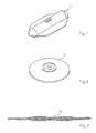
- FIG. 1is an illustration of an exemplary inner seal to be positioned into engagement with the inside surface of a blood vessel
- FIG. 2is an illustration of an exemplary outer seal to be positioned into engagement with the outer surface of a blood vessel
- FIG. 3is a longitudinal cross section of a thread tamping the inner and outer seals together
- FIG. 4is a schematic illustration of the inner and outer seals mounted together by a thread
- FIG. 5is a schematic illustration of the pusher that guides the inner seal into the blood vessel
- FIG. 6is a schematic illustration of a loading device having an introducer cone and a tamping mechanism
- FIG. 7is a schematic illustration of the introducer cone of FIG. 6 .
- FIG. 8is a schematic illustration of a feeder tube
- FIG. 9illustrates the first step in the overall sealing procedure
- FIG. 10illustrates the second step in the overall sealing procedure
- FIG. 11illustrates the third step in the overall sealing procedure
- FIG. 12illustrates the first inventive step
- FIG. 13illustrates the second inventive step
- FIG. 14illustrates the third inventive step
- FIG. 15is a sectional view of a preferred embodiment of the tamping mechanism according to the present invention.
- FIG. 16illustrates one embodiment of the cam curve included in the tamping mechanism of FIG. 15 .
- FIG. 17shows a safety mechanism for the loading device of FIG. 6 .
- FIG. 18is schematic illustration of an alternative embodiment of the tamping mechanism according to the invention.
- the three inventive stepsare general in the sense that they are included in a variety of sealing methods that involve a first element to be positioned at the inside surface of a vessel wall, a second element to be positioned at the outside surface of the vessel wall, and a clamping member that holds the first and second elements together.
- the three inventive operation stepswill be described in conjunction with a specific system for the sealing of punctures in blood vessels. A brief description of this method will be given together with a description of the designs and functions of the different elements involved in the operation.
- FIG. 1shows an inner seal 1 .
- the inner seal 1is moulded of a biodegradable polymer having rubber like elasticity and which is resorbable within six months.
- the inner seal 1can be folded into an introducer having a diameter of 2 mm. When the inner seal 1 is expanded, it reverts its original shape.
- the inner seal 1comprises a centre beam with increased cross section thickness, which prevents the inner seal 1 from being pulled out from the blood vessel when it is seated at the inside surface of the blood vessel.
- a thin and flexible skirt around the centre beamprovides the inner seal 1 with the pliability to adapt to and seal the vessel wall.
- a clamping member, in this case a thread or suture,will be drawn through the centre beam in longitudinal direction to minimise the strength reduction of the centre beam.
- FIG. 2shows an outer seal 2 .
- the outer seal 2is moulded of the same material as the inner seal 1 .
- the inner and outer sealscan be made of different materials.
- the outer seal 2comprises a thicker central portion that provides the required clamping force around the thread (suture) running through a hole in the central portion.
- a thin and flexible skirt around the central portionprovides the flexibility to adapt to the artery outside wall, and to pass through the surrounding tissue during the tamping step.
- FIG. 3illustrates schematically a clamping member 3 that tamps the inner and outer seals ( 1 , 2 ) together.
- the clamping member 3consists of a resorbable multifilament thread, suture PolysorbTM, available from US Surgical.
- a moulded core pinis inserted in the centre of the braided thread 3 . This core pin expands the diameter of the thread 3 at the portion where the thread 3 passes through the outer seal 2 . Therefore, the outer seal 2 can slide on the thread 3 without increased friction until the outer seal 2 is in engagement with the outer vessel wall and the tamping occurs.
- FIG. 4shows the inner seal 1 , the outer seal 2 and the thread 3 mounted together into a thread loop with accurate length.
- the thread 3is threaded through the respective holes in the inner and outer seals ( 1 , 2 ).
- the ends of the thread 3are joined in a stainless steel clamp 4 , which is pressed around the ends of the thread 3 .
- the ends of threadcould be joined by other means, such as glue or tape, or could be fused together etc.
- a pusher 5 illustrated in FIG. 5consists of a stainless steel wire with distal end that is flattened and formed as a fork. The pusher 5 presses against the threads 3 near the inner seal 1 . As seen in FIG. 5 , the fork end of the pusher 5 surrounds the threads 3 , and as long as the threads 3 are tightened, the pusher 5 guides the seal in all directions.
- the pushercould be made of other materials, such as plastic, and, depending on the designs of the inner and outer seals as well as of the clamping member, could have some other shape, such as tubular.
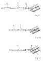
- FIG. 6is a schematic illustration of a loading device, generally marked with 6 .
- the loading device 6consists basically of two parts, an introducer cone 7 and a tamping mechanism (not shown) having a tamping button 8 .
- the tamping mechanismis accommodated in a cylindrical housing 9 , from which the tamping button 8 is partly retracted.
- the tamping mechanism and the introducer cone 7is connected through an elongated tamping member 10 .
- the elongated tamping member 10consists of a flexible tamping tube 10 .
- the tamping tube 10is attached to the tamping mechanism and can slide into the introducer cone 7 .
- the tamping mechanismwhich constitutes the basic subject of the present invention, will be described in detail below.
- FIG. 7is a schematic illustration of the introducer cone 7 shown in FIG. 6 .
- the inner and outer seals ( 1 , 2 )would be permanently stored in the folded state, they would eventually adopt this shape, and would not completely resume their original shapes after deployment.
- the seals ( 1 , 2 )are stored unfolded in a chamber in the introducer cone 7 .
- the introducer cone 7is designed with an internal gradual transition from a rectangular shape to a circular shape. As the seals ( 1 , 2 ) are pushed through the introducer cone 7 , they will therefore be folded into a circular shape.
- the thread 3 and the pusher 5are accommodated in the tamping tube 10 .
- the thread 3 and the pusher 5are conveniently guided inside the tamping tube 10 .
- the tamping membercould consist of a thin rod provided with a ring at distal end, or some other design.
- the introducer cone 7is connected to a feeder tube 11 , an example of which is shown in FIG. 8 .
- the sealing procedureis to begin, i.e. when the medical operation in the blood vessel is completed, the original introducer is replaced with this feeder tube 11 , as is illustrated in FIG. 9 .
- the inner seal 1is deployed as close to the vessel wall as possible to minimise the risk associated with the manipulation of the inner seal 1 inside the blood vessel.
- the feeder tube 11 illustrated in FIG. 8is provided with small back flow channel in the tube wall, with a distal inlet 12 approximately 1 cm from the tip and a proximal outlet 13 .
- the tip of the feeder tube 11By observing the blood drip from the channel outlet 13 it is possible to position the tip of the feeder tube 11 a suitable distance—in this case 1 cm—into the blood vessel. As is known in the art, the positioning of the feeder tube 11 can accomplished with various different methods. Further, the feeder tube 11 shown in FIG. 8 is provided with a snap fit mechanism for snap fit connection to the introducer cone 7 , but other types of connection mechanisms, such as a bayonet coupling, are possible.
- the loading device 6comprises also a tamping mechanism.
- This tamping mechanismthe function of which is the essential part of the present invention, will be thoroughly described below.
- FIG. 9the original introducer has been replaced with the feeder tube 11 .
- a person skilled in the artwould recognize how this procedure is accomplished.
- the right side of FIG. 9(as well as the right side of FIGS. 10 to 14 ), i.e. the distal end of the feeder tube 11 , has been enlarged in comparison with the left side of FIG. 9 (and FIGS. 10 - 14 ), i.e. the proximal end of the feeder tube 11 .
- the introducer cone 7is inserted into the feeder tube 11 until the introducer cone 7 and the feeder tube 11 snap together by means of the snap fit mechanism.
- the second step in the overall sealing procedureis illustrated in FIG. 10 , where the tamping mechanism being accommodated in the cylindrical housing 9 is pushed into the introducer cone 7 until the cylindrical housing 9 and the introducer cone 7 snap together. This step deploys the inner seal 1 into the blood vessel.
- FIG. 11the third step in the overall sealing procedure is illustrated.
- the loading device 6is pulled back until the inner seal 1 is seated to the inner vessel wall.
- the loading device 6is held steadily and the thread 3 is tightened.
- the fourth step in the overall sealing procedureis illustrated in FIG. 12 .
- This fourth step in the overall sealing procedureconstitutes at the same time the first step of the three inventive steps.
- the pusher 5is retracted from the inner seal 1 into the tamping tube 10 .
- the inner seal 1is now held in position by the thread 3 .
- FIG. 13illustrates the fifth step in the overall sealing procedure, i.e. the second inventive step.
- the tamping tube 10is pushed forward and tamps the inner seal 1 and the outer seal 2 together.
- FIG. 14illustrates the sixth step in the overall sealing procedure, i.e. the third and last inventive step.
- the thread loop shown in FIG. 4is released from the loading device 6 , and the loading device 6 can be removed, leaving only the thread 3 in the puncture channel.
- the position for the tamping button 8 of the loading device 6is gradually changing from a fully retracted state to a completely compressed state during the three inventive steps.
- the single manual operation of pressing down the tamping button 8actuates and accomplishes the three inventive steps.
- the functions associated with the inventive stepshave to be executed sequentially; i.e. the first function comprising the retraction of the pusher 5 must be completed before the beginning of the second function comprising the advancement of the tamping tube 10 into engagement with the outer vessel wall.
- the second functionmust, in turn, be completed before the beginning of the third function comprising the release of the thread 3 from the loading device 6 .
- the tamping mechanism according to the present inventionsatisfies these requirements.
- the three inventive stepsare executed in an essentially sequential order. In this case, some degree of overlap is allowed between some of the three inventive steps, i.e. a subsequent step may start before the preceding step has been fully completed.
- tamping mechanismshould be able to transform the movement of the tamping button 8 in the forward direction into a movement of the pusher 5 in the backward, or retracting, direction.
- the forward directionis the direction of the tamping button 8 that pushes the tamping member 10 forward into engagement with the outer vessel wall. Since the tamping member 10 in this case consists of a flexible tamping tube 10 , it is not necessary to mount the tamping mechanism and the introducer cone 7 in an aligned relation, although it seems practical.
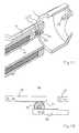
- FIG. 15A preferred embodiment of the tamping mechanism according to the present invention is illustrated in FIG. 15 .
- the tamping mechanismcomprises the pusher 5 , the thread 3 , the tamping tube 10 and the tamping button 8 as well as a plunger 14 and a cam curve 15 .
- the tamping button 8is the one end of the plunger 14 .
- the tamping buttoncould be operatively connected to the plunger by means of some force transmitting means.
- the plunger 14In the initial position shown in FIG. 15 , the plunger 14 is partly retracted from the cylindrical housing 9 . As mention in connection to FIG. 4 , the thread 3 is formed into a loop. This loop is fastened around a retainer 16 mounted at the proximal end of the cylindrical housing 9 .
- the cam curve 15is cylindrical and can rotate in the cylindrical housing 9 .
- the plunger 14 , the pusher 5 and the tamping tube 10can slide axially in the cylindrical housing 9 , but they are connected to the cam curve 15 by pins ( 17 , 18 , 19 ) that slide in grooves ( 20 , 21 , 22 ) in the surface of the cam curve 15 . In the initial position, the tamping tube 10 and the pusher 5 are locked by the cam curve 15 .
- cam curve 15The function of the cam curve 15 is more easily understood from the illustration shown in FIG. 16 , where one embodiment of the cam curve 15 is shown in an outspread state.
- a pin 17which can run in a groove 20 in the cam curve 15 , connects the tamping button 8 to the cam curve 15
- a pin 18which can run in a groove 21 , connects the pusher 5 to the cam curve 15
- a pin 19which can run in a groove 22 , connects the tamping tube 10 to the cam curve 15 .
- the pin 17 connecting the tamping button 8 to the cam curve 15is moving from the position marked with A 1 in FIG.
- the plunger 14will leave the cam curve 15 and instead press directly against the tamping tube 10 , which, in turn, pushes the outer seal 2 into engagement with the outer vessel wall, thereby tamping the outer and inner seals ( 1 , 2 ) together.
- the second inventive stepis completed. In this end position, the retainer 16 will fall down into a recess 23 (see FIG. 15 ) in the plunger 14 adjacent to the tamping button 8 , which releases the thread 3 from the retainer 16 , thereby completing the third inventive step.
- FIG. 16is merely for illustrative purposes.
- the cam curve 15is preferably cylindrical and rotates in the cylindrical housing 9 . In the outspread state shown in FIG. 16 , the corresponding motion of the cam curve 15 would therefore be in the upward direction. However, to actually let the cam curve 15 have the outspread shape shown in FIG. 16 would also work in practise, although this outspread shape might occupy more space than a cylindrical shape. Obviously, if the cam curve is not cylindrical, there is no particular reason for the housing 9 to be cylindrical.
- the last inventive stepfollows immediately after the second inventive step, which is an advantage since this minimises the risk of damaging the vessel wall or other tissue.
- the recess 23 in the plunger 14may be replaced with some other retainer actuating means 23 . If, for some reasons, the user wants to release the thread 3 by a separate manual operation, the retainer actuating means 23 could, of course, be omitted. In this case, the tamping mechanism executes only two of the three inventive steps.
- the loading device 6with a safety mechanism that prevents the accidental tamping of the outer and inner seals ( 1 , 2 ) before the seals ( 1 , 2 ) are correctly positioned at the respective sides of the vessel wall.
- a safety mechanismthat prevents the accidental tamping of the outer and inner seals ( 1 , 2 ) before the seals ( 1 , 2 ) are correctly positioned at the respective sides of the vessel wall.
- the specific design and function of such a safety mechanismwill, of course, depend on the specific design and function of the corresponding tamping mechanism.
- the safety mechanismcould be a mechanism that is manually actuated in a separate operation, or the safety mechanism could be an automatic mechanism, which means that the release of the tamping mechanism is done automatically in one of the steps included in the overall sealing procedure without any separate actions by the user. In FIG. 17 one embodiment of such a safety mechanism is illustrated.
- the safety mechanismcomprises a flexible catch 24 provided with a groove 25 , and a pin 26 .
- the catch 24constitutes in this embodiment a part of the plunger 14 and is mounted in operative engagement with the cam curve 15 .
- the pin 26is mounted inside the introducer cone 7 .
- the safety mechanismis shown before the introducer cone 7 and the cylindrical housing 9 are snapped together, i.e. before the second step in the overall sealing procedure.
- the catch 24is tilted slightly upwards and is thereby preventing the cam curve 15 from rotating.
- the groove 25being in engagement with a projection 27 from the inside surface of the cylindrical housing ( 9 ) prevents the plunger 14 from sliding into the cylindrical housing 9 .
- FIG. 18illustrates schematically an alternative embodiment of the motion transforming means according to the invention.
- the cam curve 15has been replaced with a gear mechanism, generally marked with 28 .
- the gear mechanism 28comprises a partly cogged plunger 29 , a partly cogged pusher 30 , an elongated tamping member 10 , and two gear wheels ( 31 , 32 ) connected to each other.
- the cogs of the plunger 29are initially in operative engagement with the gear wheel 31 having the larger diameter.
- the cogs of the pusher 30are initially in operative engagement with the gear wheel 32 having the smaller diameter.
- the two gear wheels ( 31 , 32 )will rotate in the clockwise direction, as illustrated in FIG. 18 .
- the gear wheel 32will therefore move the cogged pusher 30 backwards, as indicated by the arrow B, thereby executing the first inventive step.
- the plunger 29is pressed further forward, there are no more cogs in operative engagement with the gear wheel 31 , and the plunger 29 presses directly against the tamping member 10 , which moves forward, as indicated by the arrow C, thereby executing the second inventive step.
- the first inventive stepcan be completely executed before the beginning of the second inventive step.
- it is also possible to adjust the overlap between the first and second inventive stepsby adjusting the distance between the cogged plunger ( 29 ) and the tamping member ( 10 ).
Landscapes
- Health & Medical Sciences (AREA)
- Surgery (AREA)
- Life Sciences & Earth Sciences (AREA)
- Biomedical Technology (AREA)
- Nuclear Medicine, Radiotherapy & Molecular Imaging (AREA)
- Engineering & Computer Science (AREA)
- Cardiology (AREA)
- Heart & Thoracic Surgery (AREA)
- Medical Informatics (AREA)
- Molecular Biology (AREA)
- Animal Behavior & Ethology (AREA)
- General Health & Medical Sciences (AREA)
- Public Health (AREA)
- Veterinary Medicine (AREA)
- Surgical Instruments (AREA)
Abstract
Description
Claims (15)
Priority Applications (1)
| Application Number | Priority Date | Filing Date | Title |
|---|---|---|---|
| US10/170,624US6929655B2 (en) | 2001-06-15 | 2002-06-14 | Tamping mechanism |
Applications Claiming Priority (4)
| Application Number | Priority Date | Filing Date | Title |
|---|---|---|---|
| EP01850106AEP1266626B1 (en) | 2001-06-15 | 2001-06-15 | Tamping mechanism |
| EP01850106.4 | 2001-06-15 | ||
| US29889901P | 2001-06-19 | 2001-06-19 | |
| US10/170,624US6929655B2 (en) | 2001-06-15 | 2002-06-14 | Tamping mechanism |
Publications (2)
| Publication Number | Publication Date |
|---|---|
| US20030060846A1 US20030060846A1 (en) | 2003-03-27 |
| US6929655B2true US6929655B2 (en) | 2005-08-16 |
Family
ID=26077508
Family Applications (1)
| Application Number | Title | Priority Date | Filing Date |
|---|---|---|---|
| US10/170,624Expired - LifetimeUS6929655B2 (en) | 2001-06-15 | 2002-06-14 | Tamping mechanism |
Country Status (2)
| Country | Link |
|---|---|
| US (1) | US6929655B2 (en) |
| JP (1) | JP4159805B2 (en) |
Cited By (53)
| Publication number | Priority date | Publication date | Assignee | Title |
|---|---|---|---|---|
| US20040204741A1 (en)* | 2003-01-14 | 2004-10-14 | Radi Medical Systems Ab | Closure device and method for sealing a puncture in a blood vessel |
| US20050137624A1 (en)* | 2003-12-19 | 2005-06-23 | Radi Medical Systems Ab | Technique for securing a suture |
| US20060142797A1 (en)* | 2004-12-16 | 2006-06-29 | Radi Medical Systems Ab | Medical sealing device |
| US20070239209A1 (en)* | 2003-12-19 | 2007-10-11 | Radi Medical Systems Ab | Technique for securing a suture |
| US20080114395A1 (en)* | 2005-01-14 | 2008-05-15 | Radi Medical Systems Ab | Closure Device |
| EP2064999A2 (en) | 2007-11-30 | 2009-06-03 | Radi Medical Systems Ab | Insertion tool |
| US7618436B2 (en)* | 2005-04-12 | 2009-11-17 | St. Jude Medical Puerto Rico Llc | Tissue puncture closure device with scroll gear transmission tamping system |
| US7678133B2 (en) | 2004-07-10 | 2010-03-16 | Arstasis, Inc. | Biological tissue closure device and method |
| US7998169B2 (en) | 2004-05-12 | 2011-08-16 | Arstasis, Inc. | Access and closure device and method |
| US8002794B2 (en) | 2005-05-12 | 2011-08-23 | Arstasis, Inc. | Access and closure device and method |
| US20110213414A1 (en)* | 2008-02-15 | 2011-09-01 | Mcguckin Jr James F | Vascular hole closure device |
| US20110213415A1 (en)* | 2008-02-15 | 2011-09-01 | Mcguckin Jr James F | Vascular hole closure device |
| US8052914B2 (en) | 2009-02-20 | 2011-11-08 | Boston Scientific Scimed, Inc. | Modified plug for arteriotomy closure |
| US8088144B2 (en)* | 2005-05-04 | 2012-01-03 | Ensure Medical, Inc. | Locator and closure device and method of use |
| US8292918B2 (en) | 2009-02-20 | 2012-10-23 | Boston Scientific Scimed, Inc. | Composite plug for arteriotomy closure and method of use |
| US8317824B2 (en) | 2009-02-20 | 2012-11-27 | Boston Scientific Scimed, Inc. | Tissue puncture closure device |
| US8333787B2 (en) | 2007-12-31 | 2012-12-18 | St. Jude Medical Puerto Rico Llc | Vascular closure device having a flowable sealing material |
| US8375553B2 (en) | 2009-02-20 | 2013-02-19 | Boston Scientific Scimed, Inc. | Locking element for vascular closure device |
| US8382794B2 (en) | 2006-01-04 | 2013-02-26 | St. Jude Medical Puerto Rico Llc | Balloon insertion apparatus and method of sealing a tissue puncture |
| US8444673B2 (en) | 2010-02-11 | 2013-05-21 | Boston Scientific Scimed, Inc. | Automatic vascular closure deployment devices and methods |
| US8491629B2 (en) | 2008-02-15 | 2013-07-23 | Rex Medical | Vascular hole closure delivery device |
| US8506592B2 (en) | 2008-08-26 | 2013-08-13 | St. Jude Medical, Inc. | Method and system for sealing percutaneous punctures |
| US8529598B2 (en) | 2009-02-20 | 2013-09-10 | Boston Scientific Scimed, Inc. | Tissue puncture closure device |
| US8568445B2 (en) | 2007-08-21 | 2013-10-29 | St. Jude Medical Puerto Rico Llc | Extra-vascular sealing device and method |
| US8597340B2 (en) | 2010-09-17 | 2013-12-03 | Boston Scientific Scimed, Inc. | Torque mechanism actuated bioabsorbable vascular closure device |
| US8758402B2 (en) | 2010-12-17 | 2014-06-24 | Boston Scientific Scimed, Inc. | Tissue puncture closure device |
| US8840640B2 (en) | 2007-12-31 | 2014-09-23 | St. Jude Medical Puerto Rico Llc | Vascular closure device having an improved plug |
| US8968361B2 (en) | 2008-02-15 | 2015-03-03 | Rex Medical, L.P. | Vascular hole closure device |
| US8979882B2 (en) | 2008-07-21 | 2015-03-17 | Arstasis, Inc. | Devices, methods, and kits for forming tracts in tissue |
| US9226738B2 (en) | 2008-02-15 | 2016-01-05 | Rex Medical, L.P. | Vascular hole closure delivery device |
| US9282953B2 (en) | 2007-12-31 | 2016-03-15 | St. Jude Medical Puerto Rico Llc | Systems and methods for locating and closing a tissue puncture |
| US9289197B2 (en) | 2005-04-11 | 2016-03-22 | St. Jude Medical Puerto Rico Llc | Tissue puncture closure device with automatic torque sensing tamping system |
| US9463005B2 (en) | 2008-02-15 | 2016-10-11 | Rex Medical, L.P. | Vascular hole closure device |
| US9566443B2 (en) | 2013-11-26 | 2017-02-14 | Corquest Medical, Inc. | System for treating heart valve malfunction including mitral regurgitation |
| US9913634B2 (en) | 2009-02-20 | 2018-03-13 | Boston Scientific Scimed, Inc. | Locking element for vascular closure device |
| US9968345B2 (en) | 1999-09-13 | 2018-05-15 | Rex Medical, L.P. | Vascular hole closure device |
| US10154835B2 (en) | 2013-05-09 | 2018-12-18 | Essential Medical, Inc. | Vascular closure device with conforming plug member |
| US10159571B2 (en) | 2012-11-21 | 2018-12-25 | Corquest Medical, Inc. | Device and method of treating heart valve malfunction |
| USD843573S1 (en) | 2015-11-13 | 2019-03-19 | Access Closure, Inc. | Vascular closure apparatus |
| USD847988S1 (en) | 2015-11-13 | 2019-05-07 | Access Closure, Inc. | Handle grip |
| US10307167B2 (en) | 2012-12-14 | 2019-06-04 | Corquest Medical, Inc. | Assembly and method for left atrial appendage occlusion |
| US10307070B2 (en) | 2014-04-04 | 2019-06-04 | St. Jude Medical Coordination Center Bvba | Intravascular pressure and flow data diagnostic systems, devices, and methods |
| US10314594B2 (en) | 2012-12-14 | 2019-06-11 | Corquest Medical, Inc. | Assembly and method for left atrial appendage occlusion |
| US10441753B2 (en) | 2012-05-25 | 2019-10-15 | Arstasis, Inc. | Vascular access configuration |
| USD865166S1 (en) | 2015-11-13 | 2019-10-29 | Access Closure, Inc. | Sheath adapter |
| US10456123B2 (en) | 2014-11-14 | 2019-10-29 | Access Closure, Inc. | Apparatus and method for sealing a vascular puncture |
| US10648918B2 (en) | 2011-08-03 | 2020-05-12 | Lightlab Imaging, Inc. | Systems, methods and apparatus for determining a fractional flow reserve (FFR) based on the minimum lumen area (MLA) and the constant |
| US10675447B2 (en) | 2012-05-25 | 2020-06-09 | Arstasis, Inc. | Vascular access configuration |
| US10813630B2 (en) | 2011-08-09 | 2020-10-27 | Corquest Medical, Inc. | Closure system for atrial wall |
| US10842626B2 (en) | 2014-12-09 | 2020-11-24 | Didier De Canniere | Intracardiac device to correct mitral regurgitation |
| US11241154B2 (en) | 2011-05-31 | 2022-02-08 | Lightlab Imaging, Inc. | Multimodal imaging system, apparatus, and methods |
| US11504105B2 (en) | 2019-01-25 | 2022-11-22 | Rex Medical L.P. | Vascular hole closure device |
| US12383246B2 (en) | 2020-10-12 | 2025-08-12 | Abbott Cardiovascular Systems, Inc. | Vessel closure device with improved safety and tract hemostasis |
Families Citing this family (76)
| Publication number | Priority date | Publication date | Assignee | Title |
|---|---|---|---|---|
| US7842068B2 (en) | 2000-12-07 | 2010-11-30 | Integrated Vascular Systems, Inc. | Apparatus and methods for providing tactile feedback while delivering a closure device |
| US6461364B1 (en) | 2000-01-05 | 2002-10-08 | Integrated Vascular Systems, Inc. | Vascular sheath with bioabsorbable puncture site closure apparatus and methods of use |
| US9579091B2 (en) | 2000-01-05 | 2017-02-28 | Integrated Vascular Systems, Inc. | Closure system and methods of use |
| US6391048B1 (en) | 2000-01-05 | 2002-05-21 | Integrated Vascular Systems, Inc. | Integrated vascular device with puncture site closure component and sealant and methods of use |
| US8758400B2 (en) | 2000-01-05 | 2014-06-24 | Integrated Vascular Systems, Inc. | Closure system and methods of use |
| DE60144328D1 (en)* | 2000-09-08 | 2011-05-12 | Abbott Vascular Inc | Surgical clamp |
| US6626918B1 (en)* | 2000-10-06 | 2003-09-30 | Medical Technology Group | Apparatus and methods for positioning a vascular sheath |
| US7905900B2 (en) | 2003-01-30 | 2011-03-15 | Integrated Vascular Systems, Inc. | Clip applier and methods of use |
| US6695867B2 (en) | 2002-02-21 | 2004-02-24 | Integrated Vascular Systems, Inc. | Plunger apparatus and methods for delivering a closure device |
| US8690910B2 (en) | 2000-12-07 | 2014-04-08 | Integrated Vascular Systems, Inc. | Closure device and methods for making and using them |
| US7211101B2 (en) | 2000-12-07 | 2007-05-01 | Abbott Vascular Devices | Methods for manufacturing a clip and clip |
| US6623510B2 (en) | 2000-12-07 | 2003-09-23 | Integrated Vascular Systems, Inc. | Closure device and methods for making and using them |
| IES20010547A2 (en) | 2001-06-07 | 2002-12-11 | Christy Cummins | Surgical Staple |
| IES20030424A2 (en) | 2002-06-04 | 2003-12-10 | Robert Stevenson | Blood vessel closure clip and delivery device |
| US8202293B2 (en) | 2003-01-30 | 2012-06-19 | Integrated Vascular Systems, Inc. | Clip applier and methods of use |
| US8905937B2 (en) | 2009-02-26 | 2014-12-09 | Integrated Vascular Systems, Inc. | Methods and apparatus for locating a surface of a body lumen |
| US8758398B2 (en) | 2006-09-08 | 2014-06-24 | Integrated Vascular Systems, Inc. | Apparatus and method for delivering a closure element |
| US8398656B2 (en) | 2003-01-30 | 2013-03-19 | Integrated Vascular Systems, Inc. | Clip applier and methods of use |
| IES20040368A2 (en) | 2004-05-25 | 2005-11-30 | James E Coleman | Surgical stapler |
| US7250057B2 (en) | 2005-04-11 | 2007-07-31 | St. Jude Medical Puerto Rico B.V. | Tissue puncture closure device with automatic torque sensing tamping system |
| EP1879505B1 (en)* | 2005-04-29 | 2012-10-24 | Vivasure Medical Limited | An interventional medical closure device |
| US7837705B2 (en)* | 2005-05-17 | 2010-11-23 | St. Jude Medical Puerto Rico Llc | Tissue puncture closure system with retractable sheath |
| US8926633B2 (en) | 2005-06-24 | 2015-01-06 | Abbott Laboratories | Apparatus and method for delivering a closure element |
| US8313497B2 (en) | 2005-07-01 | 2012-11-20 | Abbott Laboratories | Clip applier and methods of use |
| US7749247B2 (en)* | 2005-08-04 | 2010-07-06 | St. Jude Medical Puerto Rico, Llc | Tissue puncture closure device with coiled automatic tamping system |
| US20070078432A1 (en)* | 2005-09-06 | 2007-04-05 | Halseth Thor R | Adjustable medication infusion injection apparatus |
| US8808310B2 (en) | 2006-04-20 | 2014-08-19 | Integrated Vascular Systems, Inc. | Resettable clip applier and reset tools |
| US8556930B2 (en) | 2006-06-28 | 2013-10-15 | Abbott Laboratories | Vessel closure device |
| US7749248B2 (en)* | 2006-09-18 | 2010-07-06 | St. Jude Medical Puerto Rico Llc | Flexible tamping device |
| EP2152168A2 (en)* | 2007-05-04 | 2010-02-17 | Maquet Cardiovascular LLC | Methods and devices for loading temporary hemostatic seals |
| US9610070B2 (en) | 2007-06-15 | 2017-04-04 | Vivasure Medical Limited | Closure device |
| US8893947B2 (en) | 2007-12-17 | 2014-11-25 | Abbott Laboratories | Clip applier and methods of use |
| US20090157101A1 (en)* | 2007-12-17 | 2009-06-18 | Abbott Laboratories | Tissue closure system and methods of use |
| US7841502B2 (en) | 2007-12-18 | 2010-11-30 | Abbott Laboratories | Modular clip applier |
| JP5290717B2 (en)* | 2008-02-21 | 2013-09-18 | テルモ株式会社 | In vivo tissue closure device |
| US9282965B2 (en) | 2008-05-16 | 2016-03-15 | Abbott Laboratories | Apparatus and methods for engaging tissue |
| US8398676B2 (en) | 2008-10-30 | 2013-03-19 | Abbott Vascular Inc. | Closure device |
| WO2010056915A1 (en)* | 2008-11-12 | 2010-05-20 | Accessclosure, Inc. | Apparatus and methods for sealing a vascular puncture |
| US8858594B2 (en) | 2008-12-22 | 2014-10-14 | Abbott Laboratories | Curved closure device |
| US9414820B2 (en) | 2009-01-09 | 2016-08-16 | Abbott Vascular Inc. | Closure devices, systems, and methods |
| US9173644B2 (en)* | 2009-01-09 | 2015-11-03 | Abbott Vascular Inc. | Closure devices, systems, and methods |
| US9089311B2 (en) | 2009-01-09 | 2015-07-28 | Abbott Vascular Inc. | Vessel closure devices and methods |
| US20100179589A1 (en) | 2009-01-09 | 2010-07-15 | Abbott Vascular Inc. | Rapidly eroding anchor |
| US20100179567A1 (en)* | 2009-01-09 | 2010-07-15 | Abbott Vascular Inc. | Closure devices, systems, and methods |
| US20110218568A1 (en)* | 2009-01-09 | 2011-09-08 | Voss Laveille K | Vessel closure devices, systems, and methods |
| US9486191B2 (en) | 2009-01-09 | 2016-11-08 | Abbott Vascular, Inc. | Closure devices |
| US20100185234A1 (en)* | 2009-01-16 | 2010-07-22 | Abbott Vascular Inc. | Closure devices, systems, and methods |
| US20110054492A1 (en) | 2009-08-26 | 2011-03-03 | Abbott Laboratories | Medical device for repairing a fistula |
| US8870950B2 (en) | 2009-12-08 | 2014-10-28 | Mitral Tech Ltd. | Rotation-based anchoring of an implant |
| WO2011080588A2 (en) | 2009-12-30 | 2011-07-07 | Vivasure Medical Limited | Closure system and uses thereof |
| US20110224785A1 (en) | 2010-03-10 | 2011-09-15 | Hacohen Gil | Prosthetic mitral valve with tissue anchors |
| US11653910B2 (en) | 2010-07-21 | 2023-05-23 | Cardiovalve Ltd. | Helical anchor implantation |
| US8758399B2 (en) | 2010-08-02 | 2014-06-24 | Abbott Cardiovascular Systems, Inc. | Expandable bioabsorbable plug apparatus and method |
| US8603116B2 (en) | 2010-08-04 | 2013-12-10 | Abbott Cardiovascular Systems, Inc. | Closure device with long tines |
| WO2012090069A2 (en) | 2010-12-30 | 2012-07-05 | Vivasure Medical Limited | Surgical closure systems and methods |
| US9149276B2 (en) | 2011-03-21 | 2015-10-06 | Abbott Cardiovascular Systems, Inc. | Clip and deployment apparatus for tissue closure |
| EP2739214B1 (en) | 2011-08-05 | 2018-10-10 | Cardiovalve Ltd | Percutaneous mitral valve replacement and sealing |
| WO2013021374A2 (en) | 2011-08-05 | 2013-02-14 | Mitraltech Ltd. | Techniques for percutaneous mitral valve replacement and sealing |
| US9332976B2 (en) | 2011-11-30 | 2016-05-10 | Abbott Cardiovascular Systems, Inc. | Tissue closure device |
| US9572558B2 (en) | 2012-02-29 | 2017-02-21 | Vivasure Medical Limited | Devices and methods for delivering implants for percutaneous perforation closure |
| US9364209B2 (en) | 2012-12-21 | 2016-06-14 | Abbott Cardiovascular Systems, Inc. | Articulating suturing device |
| US20150351906A1 (en) | 2013-01-24 | 2015-12-10 | Mitraltech Ltd. | Ventricularly-anchored prosthetic valves |
| US9850013B2 (en) | 2013-03-15 | 2017-12-26 | Vivasure Medical Limited | Loading devices and methods for percutaneous perforation closure systems |
| EP3174502B1 (en) | 2014-07-30 | 2022-04-06 | Cardiovalve Ltd | Apparatus for implantation of an articulatable prosthetic valve |
| US10433826B2 (en) | 2014-12-15 | 2019-10-08 | Vivasure Medical Limited | Closure apparatus with flexible sealable member and flexible support member |
| US11141142B2 (en) | 2014-12-15 | 2021-10-12 | Vivasure Medical Limited | Implantable sealable member with mesh layer |
| CN110141399B (en) | 2015-02-05 | 2021-07-27 | 卡迪尔维尔福股份有限公司 | Prosthetic valve with axial sliding frame |
| WO2017102941A1 (en) | 2015-12-15 | 2017-06-22 | Vivasure Medical Limited | Arteriotomy closure apparatus with slotted shoe for advantageous pressure distribution |
| US10531866B2 (en) | 2016-02-16 | 2020-01-14 | Cardiovalve Ltd. | Techniques for providing a replacement valve and transseptal communication |
| US20190231525A1 (en) | 2016-08-01 | 2019-08-01 | Mitraltech Ltd. | Minimally-invasive delivery systems |
| CA3031187A1 (en) | 2016-08-10 | 2018-02-15 | Cardiovalve Ltd. | Prosthetic valve with concentric frames |
| US10888421B2 (en) | 2017-09-19 | 2021-01-12 | Cardiovalve Ltd. | Prosthetic heart valve with pouch |
| US11793633B2 (en) | 2017-08-03 | 2023-10-24 | Cardiovalve Ltd. | Prosthetic heart valve |
| US12064347B2 (en) | 2017-08-03 | 2024-08-20 | Cardiovalve Ltd. | Prosthetic heart valve |
| KR20240150538A (en) | 2018-01-29 | 2024-10-15 | 액세스클로저, 아이엔씨. | Apparatus and method for sealing a vascular puncture |
| US12357459B2 (en) | 2020-12-03 | 2025-07-15 | Cardiovalve Ltd. | Transluminal delivery system |
Citations (10)
| Publication number | Priority date | Publication date | Assignee | Title |
|---|---|---|---|---|
| US5021059A (en) | 1990-05-07 | 1991-06-04 | Kensey Nash Corporation | Plug device with pulley for sealing punctures in tissue and methods of use |
| US5222974A (en)* | 1991-11-08 | 1993-06-29 | Kensey Nash Corporation | Hemostatic puncture closure system and method of use |
| US5282827A (en) | 1991-11-08 | 1994-02-01 | Kensey Nash Corporation | Hemostatic puncture closure system and method of use |
| US5342393A (en) | 1992-08-27 | 1994-08-30 | Duke University | Method and device for vascular repair |
| US5350399A (en) | 1991-09-23 | 1994-09-27 | Jay Erlebacher | Percutaneous arterial puncture seal device and insertion tool therefore |
| US5411520A (en)* | 1991-11-08 | 1995-05-02 | Kensey Nash Corporation | Hemostatic vessel puncture closure system utilizing a plug located within the puncture tract spaced from the vessel, and method of use |
| US5620461A (en) | 1989-05-29 | 1997-04-15 | Muijs Van De Moer; Wouter M. | Sealing device |
| US6090130A (en)* | 1991-11-08 | 2000-07-18 | Kensey Nash Corporation | Hemostatic puncture closure system including blood vessel locator and method of use |
| WO2000078226A1 (en) | 1999-06-18 | 2000-12-28 | Radi Medical Systems Ab | A tool, a sealing device, a system and a method for closing a wound |
| US6425911B1 (en)* | 2001-05-09 | 2002-07-30 | Radi Medical Systems Ab | Positioning device and incision closure device |
- 2002
- 2002-05-30JPJP2002156807Apatent/JP4159805B2/ennot_activeExpired - Fee Related
- 2002-06-14USUS10/170,624patent/US6929655B2/ennot_activeExpired - Lifetime
Patent Citations (14)
| Publication number | Priority date | Publication date | Assignee | Title |
|---|---|---|---|---|
| US5620461A (en) | 1989-05-29 | 1997-04-15 | Muijs Van De Moer; Wouter M. | Sealing device |
| US5021059A (en) | 1990-05-07 | 1991-06-04 | Kensey Nash Corporation | Plug device with pulley for sealing punctures in tissue and methods of use |
| US5350399A (en) | 1991-09-23 | 1994-09-27 | Jay Erlebacher | Percutaneous arterial puncture seal device and insertion tool therefore |
| US5935147A (en)* | 1991-11-08 | 1999-08-10 | Kensey Nash Corporation | Hemostatic puncture closure system and method of use |
| US5411520A (en)* | 1991-11-08 | 1995-05-02 | Kensey Nash Corporation | Hemostatic vessel puncture closure system utilizing a plug located within the puncture tract spaced from the vessel, and method of use |
| US5441517A (en) | 1991-11-08 | 1995-08-15 | Kensey Nash Corporation | Hemostatic puncture closure system and method of use |
| US5282827A (en) | 1991-11-08 | 1994-02-01 | Kensey Nash Corporation | Hemostatic puncture closure system and method of use |
| US5707393A (en)* | 1991-11-08 | 1998-01-13 | Kensey Nash Corporation | Hemostatic puncture closure system and method of use |
| US5222974A (en)* | 1991-11-08 | 1993-06-29 | Kensey Nash Corporation | Hemostatic puncture closure system and method of use |
| US6007563A (en)* | 1991-11-08 | 1999-12-28 | Kensey Nash Corporation | Method of deploying percutaneous puncture closure |
| US6090130A (en)* | 1991-11-08 | 2000-07-18 | Kensey Nash Corporation | Hemostatic puncture closure system including blood vessel locator and method of use |
| US5342393A (en) | 1992-08-27 | 1994-08-30 | Duke University | Method and device for vascular repair |
| WO2000078226A1 (en) | 1999-06-18 | 2000-12-28 | Radi Medical Systems Ab | A tool, a sealing device, a system and a method for closing a wound |
| US6425911B1 (en)* | 2001-05-09 | 2002-07-30 | Radi Medical Systems Ab | Positioning device and incision closure device |
Cited By (95)
| Publication number | Priority date | Publication date | Assignee | Title |
|---|---|---|---|---|
| US9968345B2 (en) | 1999-09-13 | 2018-05-15 | Rex Medical, L.P. | Vascular hole closure device |
| US8512372B2 (en) | 2003-01-14 | 2013-08-20 | Radi Medical Systems Ab | Closure device and method for sealing a puncture in a blood vessel |
| US20040204741A1 (en)* | 2003-01-14 | 2004-10-14 | Radi Medical Systems Ab | Closure device and method for sealing a puncture in a blood vessel |
| US8118831B2 (en)* | 2003-01-14 | 2012-02-21 | Radi Medical Systems Ab | Closure device and method for sealing a puncture in a blood vessel |
| US8267959B2 (en) | 2003-12-19 | 2012-09-18 | Radi Medical Systems Ab | Technique for securing a suture |
| US7717929B2 (en) | 2003-12-19 | 2010-05-18 | Radi Medical Systems Ab | Technique for securing a suture |
| US20050137624A1 (en)* | 2003-12-19 | 2005-06-23 | Radi Medical Systems Ab | Technique for securing a suture |
| US20070239209A1 (en)* | 2003-12-19 | 2007-10-11 | Radi Medical Systems Ab | Technique for securing a suture |
| US8002793B2 (en) | 2004-05-12 | 2011-08-23 | Arstasis, Inc. | Access and closure device and method |
| US7998169B2 (en) | 2004-05-12 | 2011-08-16 | Arstasis, Inc. | Access and closure device and method |
| US8002791B2 (en) | 2004-05-12 | 2011-08-23 | Arstasis, Inc. | Access and closure device and method |
| US8002792B2 (en) | 2004-05-12 | 2011-08-23 | Arstasis, Inc. | Access and closure device and method |
| US8012168B2 (en) | 2004-05-12 | 2011-09-06 | Arstasis, Inc. | Access and closure device and method |
| US7678133B2 (en) | 2004-07-10 | 2010-03-16 | Arstasis, Inc. | Biological tissue closure device and method |
| US20060142797A1 (en)* | 2004-12-16 | 2006-06-29 | Radi Medical Systems Ab | Medical sealing device |
| US8105352B2 (en) | 2004-12-16 | 2012-01-31 | Radi Medical Systems Ab | Medical sealing device |
| US20080114395A1 (en)* | 2005-01-14 | 2008-05-15 | Radi Medical Systems Ab | Closure Device |
| US9289197B2 (en) | 2005-04-11 | 2016-03-22 | St. Jude Medical Puerto Rico Llc | Tissue puncture closure device with automatic torque sensing tamping system |
| US7618436B2 (en)* | 2005-04-12 | 2009-11-17 | St. Jude Medical Puerto Rico Llc | Tissue puncture closure device with scroll gear transmission tamping system |
| US8088144B2 (en)* | 2005-05-04 | 2012-01-03 | Ensure Medical, Inc. | Locator and closure device and method of use |
| US8002794B2 (en) | 2005-05-12 | 2011-08-23 | Arstasis, Inc. | Access and closure device and method |
| US8083767B2 (en) | 2005-05-12 | 2011-12-27 | Arstasis, Inc. | Access and closure device and method |
| US8241325B2 (en) | 2005-05-12 | 2012-08-14 | Arstasis, Inc. | Access and closure device and method |
| US8382794B2 (en) | 2006-01-04 | 2013-02-26 | St. Jude Medical Puerto Rico Llc | Balloon insertion apparatus and method of sealing a tissue puncture |
| US9254346B2 (en) | 2007-08-21 | 2016-02-09 | St. Jude Medical Puerto Rico Llc | Vascular closure device having a flowable sealing material |
| US8568445B2 (en) | 2007-08-21 | 2013-10-29 | St. Jude Medical Puerto Rico Llc | Extra-vascular sealing device and method |
| US9913635B2 (en) | 2007-08-21 | 2018-03-13 | St. Jude Medical Puerto Rico Llc | Vascular closure device having a flowable sealing material |
| US9585645B2 (en) | 2007-11-30 | 2017-03-07 | St. Jude Medical Coordination Center Bvba | Insertion tool for a medical closure device |
| US10390809B2 (en) | 2007-11-30 | 2019-08-27 | Terumo Europe N.V. | Insertion tool for a medical closure device |
| EP2064999A2 (en) | 2007-11-30 | 2009-06-03 | Radi Medical Systems Ab | Insertion tool |
| US20090143817A1 (en)* | 2007-11-30 | 2009-06-04 | Radi Medical Systems Ab | Insertion tool for a medical closure device |
| US8652166B2 (en) | 2007-11-30 | 2014-02-18 | Radi Medical Systems Ab | Insertion tool for a medical closure device |
| US8333787B2 (en) | 2007-12-31 | 2012-12-18 | St. Jude Medical Puerto Rico Llc | Vascular closure device having a flowable sealing material |
| US9282953B2 (en) | 2007-12-31 | 2016-03-15 | St. Jude Medical Puerto Rico Llc | Systems and methods for locating and closing a tissue puncture |
| US8840640B2 (en) | 2007-12-31 | 2014-09-23 | St. Jude Medical Puerto Rico Llc | Vascular closure device having an improved plug |
| US9226738B2 (en) | 2008-02-15 | 2016-01-05 | Rex Medical, L.P. | Vascular hole closure delivery device |
| US11020104B2 (en) | 2008-02-15 | 2021-06-01 | Rex Medical L.P. | Vascular hole closure delivery device |
| US12349883B2 (en) | 2008-02-15 | 2025-07-08 | Rex Medical, L.P. | Vascular hole closure device |
| US11369354B2 (en) | 2008-02-15 | 2022-06-28 | Rex Medical L.P. | Vascular hole closure delivery device |
| US20110213415A1 (en)* | 2008-02-15 | 2011-09-01 | Mcguckin Jr James F | Vascular hole closure device |
| US9943300B2 (en) | 2008-02-15 | 2018-04-17 | Rex Medical, L.P. | Vascular hole closure device |
| US8920463B2 (en) | 2008-02-15 | 2014-12-30 | Rex Medical, L.P. | Vascular hole closure device |
| US8920462B2 (en) | 2008-02-15 | 2014-12-30 | Rex Medical, L.P. | Vascular hole closure device |
| US8968361B2 (en) | 2008-02-15 | 2015-03-03 | Rex Medical, L.P. | Vascular hole closure device |
| US9924930B2 (en) | 2008-02-15 | 2018-03-27 | Rex Medical, L.P. | Vascular hole closure device |
| US8491629B2 (en) | 2008-02-15 | 2013-07-23 | Rex Medical | Vascular hole closure delivery device |
| US11123059B2 (en) | 2008-02-15 | 2021-09-21 | Rex Medical, L.P. | Vascular hole closure delivery device |
| US11064986B2 (en) | 2008-02-15 | 2021-07-20 | Rex Medical, L.P. | Vascular hole closure device |
| US10004486B2 (en) | 2008-02-15 | 2018-06-26 | Rex Medical, L.P. | Vascular hole closure delivery device |
| US20110213414A1 (en)* | 2008-02-15 | 2011-09-01 | Mcguckin Jr James F | Vascular hole closure device |
| US9295458B2 (en) | 2008-02-15 | 2016-03-29 | Rex Medical, L.P. | Vascular hole closure delivery device |
| US10390808B2 (en) | 2008-02-15 | 2019-08-27 | Rex Medical, L.P | Vascular hole closure device |
| US9339261B2 (en) | 2008-02-15 | 2016-05-17 | Rex Medical, L.P. | Vascular hole closure delivery device |
| US9463005B2 (en) | 2008-02-15 | 2016-10-11 | Rex Medical, L.P. | Vascular hole closure device |
| US10390807B2 (en) | 2008-02-15 | 2019-08-27 | Rex Medical, L.P. | Vascular hole closure device |
| US10342524B2 (en) | 2008-02-15 | 2019-07-09 | Rex Medical, L.P. | Vascular hole closure device |
| US9782155B2 (en) | 2008-02-15 | 2017-10-10 | Rex Medical, L.P. | Vascular hole closure device |
| US10108646B2 (en) | 2008-02-15 | 2018-10-23 | Rex Medical, L.P. | Vascular hole closure delivery device |
| US10098621B2 (en) | 2008-02-15 | 2018-10-16 | Rex Medical, Lp. | Vascular hole closure delivery device |
| US8979882B2 (en) | 2008-07-21 | 2015-03-17 | Arstasis, Inc. | Devices, methods, and kits for forming tracts in tissue |
| US8845683B2 (en) | 2008-08-26 | 2014-09-30 | St. Jude Medical, Inc. | Method and system for sealing percutaneous punctures |
| US8506592B2 (en) | 2008-08-26 | 2013-08-13 | St. Jude Medical, Inc. | Method and system for sealing percutaneous punctures |
| US8317824B2 (en) | 2009-02-20 | 2012-11-27 | Boston Scientific Scimed, Inc. | Tissue puncture closure device |
| US9282955B2 (en) | 2009-02-20 | 2016-03-15 | Boston Scientific Scimed, Inc. | Tissue puncture closure device |
| US8052914B2 (en) | 2009-02-20 | 2011-11-08 | Boston Scientific Scimed, Inc. | Modified plug for arteriotomy closure |
| US8529598B2 (en) | 2009-02-20 | 2013-09-10 | Boston Scientific Scimed, Inc. | Tissue puncture closure device |
| US8375553B2 (en) | 2009-02-20 | 2013-02-19 | Boston Scientific Scimed, Inc. | Locking element for vascular closure device |
| US10363020B2 (en) | 2009-02-20 | 2019-07-30 | Boston Scientific Scimed Inc. | Composite plug for arteriotomy closure and method of use |
| US8292918B2 (en) | 2009-02-20 | 2012-10-23 | Boston Scientific Scimed, Inc. | Composite plug for arteriotomy closure and method of use |
| US9913634B2 (en) | 2009-02-20 | 2018-03-13 | Boston Scientific Scimed, Inc. | Locking element for vascular closure device |
| US9301740B2 (en) | 2010-02-11 | 2016-04-05 | Boston Scientific Scimed, Inc. | Automatic vascular closure deployment devices and methods |
| US8444673B2 (en) | 2010-02-11 | 2013-05-21 | Boston Scientific Scimed, Inc. | Automatic vascular closure deployment devices and methods |
| US8597340B2 (en) | 2010-09-17 | 2013-12-03 | Boston Scientific Scimed, Inc. | Torque mechanism actuated bioabsorbable vascular closure device |
| US8758402B2 (en) | 2010-12-17 | 2014-06-24 | Boston Scientific Scimed, Inc. | Tissue puncture closure device |
| US11241154B2 (en) | 2011-05-31 | 2022-02-08 | Lightlab Imaging, Inc. | Multimodal imaging system, apparatus, and methods |
| US10648918B2 (en) | 2011-08-03 | 2020-05-12 | Lightlab Imaging, Inc. | Systems, methods and apparatus for determining a fractional flow reserve (FFR) based on the minimum lumen area (MLA) and the constant |
| US10813630B2 (en) | 2011-08-09 | 2020-10-27 | Corquest Medical, Inc. | Closure system for atrial wall |
| US10441753B2 (en) | 2012-05-25 | 2019-10-15 | Arstasis, Inc. | Vascular access configuration |
| US10675447B2 (en) | 2012-05-25 | 2020-06-09 | Arstasis, Inc. | Vascular access configuration |
| US10159571B2 (en) | 2012-11-21 | 2018-12-25 | Corquest Medical, Inc. | Device and method of treating heart valve malfunction |
| US10314594B2 (en) | 2012-12-14 | 2019-06-11 | Corquest Medical, Inc. | Assembly and method for left atrial appendage occlusion |
| US10307167B2 (en) | 2012-12-14 | 2019-06-04 | Corquest Medical, Inc. | Assembly and method for left atrial appendage occlusion |
| US10154835B2 (en) | 2013-05-09 | 2018-12-18 | Essential Medical, Inc. | Vascular closure device with conforming plug member |
| US9566443B2 (en) | 2013-11-26 | 2017-02-14 | Corquest Medical, Inc. | System for treating heart valve malfunction including mitral regurgitation |
| US11559218B2 (en) | 2014-04-04 | 2023-01-24 | St. Jude Medical Coordination Center Bvba | Intravascular pressure and flow data diagnostic systems, devices, and methods |
| US10307070B2 (en) | 2014-04-04 | 2019-06-04 | St. Jude Medical Coordination Center Bvba | Intravascular pressure and flow data diagnostic systems, devices, and methods |
| US10456123B2 (en) | 2014-11-14 | 2019-10-29 | Access Closure, Inc. | Apparatus and method for sealing a vascular puncture |
| US11832804B2 (en) | 2014-11-14 | 2023-12-05 | Access Closure, Inc. | Apparatus and method for sealing a vascular puncture |
| US10842626B2 (en) | 2014-12-09 | 2020-11-24 | Didier De Canniere | Intracardiac device to correct mitral regurgitation |
| USD847988S1 (en) | 2015-11-13 | 2019-05-07 | Access Closure, Inc. | Handle grip |
| USD843573S1 (en) | 2015-11-13 | 2019-03-19 | Access Closure, Inc. | Vascular closure apparatus |
| USD1042819S1 (en) | 2015-11-13 | 2024-09-17 | Access Closure, Inc. | Sheath adapter |
| USD865166S1 (en) | 2015-11-13 | 2019-10-29 | Access Closure, Inc. | Sheath adapter |
| US11504105B2 (en) | 2019-01-25 | 2022-11-22 | Rex Medical L.P. | Vascular hole closure device |
| US12383246B2 (en) | 2020-10-12 | 2025-08-12 | Abbott Cardiovascular Systems, Inc. | Vessel closure device with improved safety and tract hemostasis |
Also Published As
| Publication number | Publication date |
|---|---|
| JP2003024335A (en) | 2003-01-28 |
| US20030060846A1 (en) | 2003-03-27 |
| JP4159805B2 (en) | 2008-10-01 |
Similar Documents
| Publication | Publication Date | Title |
|---|---|---|
| US6929655B2 (en) | Tamping mechanism | |
| EP1266626B1 (en) | Tamping mechanism | |
| US7803167B2 (en) | Handle for suturing apparatus | |
| US6024747A (en) | Device and method for suturing blood vessels and the like | |
| US8709020B2 (en) | Suturing device and method for sealing an opening in a blood vessel or other biological structure | |
| US6428549B1 (en) | Device and method for suturing blood vessels and the like | |
| US5997555A (en) | Device and method for suturing blood vessels | |
| US6641592B1 (en) | System for wound closure | |
| US10555727B2 (en) | Vascular closure device with removable guide member | |
| CN107106151B (en) | Apparatus and method for sealing vascular perforations | |
| CN109069139B (en) | Vessel closure system with introducer for sheath transfer | |
| JP2003502097A (en) | Wound closure device, closure device, device and method | |
| US20240138824A1 (en) | Vascular closure devices and methods | |
| CN109700566B (en) | Conveying device and system | |
| WO2001067963A2 (en) | Suturing device and method | |
| AU2003212025A1 (en) | Suturing device for sealing an opening in a blood vessel |
Legal Events
| Date | Code | Title | Description |
|---|---|---|---|
| AS | Assignment | Owner name:RADI MEDICAL SYSTEMS AB, SWEDEN Free format text:ASSIGNMENT OF ASSIGNORS INTEREST;ASSIGNORS:EGNELOV, PER;AKERFELDT, DAN;PREINITZ, FREDRIK;REEL/FRAME:013002/0186 Effective date:20020610 | |
| STCF | Information on status: patent grant | Free format text:PATENTED CASE | |
| FEPP | Fee payment procedure | Free format text:PAT HOLDER NO LONGER CLAIMS SMALL ENTITY STATUS, ENTITY STATUS SET TO UNDISCOUNTED (ORIGINAL EVENT CODE: STOL); ENTITY STATUS OF PATENT OWNER: LARGE ENTITY Free format text:PAYOR NUMBER ASSIGNED (ORIGINAL EVENT CODE: ASPN); ENTITY STATUS OF PATENT OWNER: LARGE ENTITY | |
| FPAY | Fee payment | Year of fee payment:4 | |
| FPAY | Fee payment | Year of fee payment:8 | |
| AS | Assignment | Owner name:ST. JUDE MEDICAL SYSTEMS AB, SWEDEN Free format text:CHANGE OF NAME;ASSIGNOR:RADI MEDICAL SYSTEMS AB;REEL/FRAME:034796/0153 Effective date:20091127 | |
| AS | Assignment | Owner name:ST. JUDE MEDICAL COORDINATION CENTER BVBA, BELGIUM Free format text:ASSIGNMENT OF ASSIGNORS INTEREST;ASSIGNOR:ST. JUDE MEDICAL SYSTEMS AB;REEL/FRAME:035169/0705 Effective date:20140923 | |
| AS | Assignment | Owner name:TERUMO EUROPE N.V., BELGIUM Free format text:ASSIGNMENT OF ASSIGNORS INTEREST;ASSIGNOR:ST. JUDE MEDICAL COORDINATION CENTER BVBA;REEL/FRAME:041120/0563 Effective date:20170116 | |
| FPAY | Fee payment | Year of fee payment:12 | |
| AS | Assignment | Owner name:TERUMO MEDICAL CORPORATION, NEW JERSEY Free format text:ASSIGNMENT OF ASSIGNORS INTEREST;ASSIGNOR:TERUMO EUROPE N.V.;REEL/FRAME:056010/0357 Effective date:20210226 |