US6928673B2 - Siderail pad for hospital bed - Google Patents
Siderail pad for hospital bedDownload PDFInfo
- Publication number
- US6928673B2 US6928673B2US10/627,226US62722603AUS6928673B2US 6928673 B2US6928673 B2US 6928673B2US 62722603 AUS62722603 AUS 62722603AUS 6928673 B2US6928673 B2US 6928673B2
- Authority
- US
- United States
- Prior art keywords
- siderail
- mattress
- patient
- frame
- coupled
- Prior art date
- Legal status (The legal status is an assumption and is not a legal conclusion. Google has not performed a legal analysis and makes no representation as to the accuracy of the status listed.)
- Expired - Lifetime
Links
- 239000006260foamSubstances0.000claimsdescription36
- 239000012858resilient materialSubstances0.000claimsdescription24
- 239000000945fillerSubstances0.000claimsdescription9
- 230000000903blocking effectEffects0.000claimsdescription7
- 230000004888barrier functionEffects0.000claims8
- 229920003023plasticPolymers0.000description21
- 239000004033plasticSubstances0.000description21
- 239000000463materialSubstances0.000description19
- 230000009970fire resistant effectEffects0.000description15
- 239000006261foam materialSubstances0.000description13
- 230000008878couplingEffects0.000description12
- 238000010168coupling processMethods0.000description12
- 238000005859coupling reactionMethods0.000description12
- 230000001681protective effectEffects0.000description11
- 230000007246mechanismEffects0.000description9
- 239000004677NylonSubstances0.000description7
- 229920001778nylonPolymers0.000description7
- 125000000391vinyl groupChemical group[H]C([*])=C([H])[H]0.000description7
- 229920002554vinyl polymerPolymers0.000description7
- 210000000689upper legAnatomy0.000description6
- 238000010276constructionMethods0.000description4
- 238000000034methodMethods0.000description4
- 230000000284resting effectEffects0.000description4
- 230000002787reinforcementEffects0.000description3
- 238000007665saggingMethods0.000description3
- 229920000271Kevlar®Polymers0.000description2
- 229920005830Polyurethane FoamPolymers0.000description2
- 239000000853adhesiveSubstances0.000description2
- 230000001070adhesive effectEffects0.000description2
- 238000013459approachMethods0.000description2
- 230000000994depressogenic effectEffects0.000description2
- 239000011152fibreglassSubstances0.000description2
- 238000003780insertionMethods0.000description2
- 230000037431insertionEffects0.000description2
- 239000011496polyurethane foamSubstances0.000description2
- 208000027418Wounds and injuryDiseases0.000description1
- 238000004140cleaningMethods0.000description1
- 238000000576coating methodMethods0.000description1
- 230000006378damageEffects0.000description1
- 230000003028elevating effectEffects0.000description1
- 230000005484gravityEffects0.000description1
- 208000014674injuryDiseases0.000description1
- 230000007774longtermEffects0.000description1
- 238000012986modificationMethods0.000description1
- 230000004048modificationEffects0.000description1
- 230000000474nursing effectEffects0.000description1
Images


Classifications
- A—HUMAN NECESSITIES
- A61—MEDICAL OR VETERINARY SCIENCE; HYGIENE
- A61G—TRANSPORT, PERSONAL CONVEYANCES, OR ACCOMMODATION SPECIALLY ADAPTED FOR PATIENTS OR DISABLED PERSONS; OPERATING TABLES OR CHAIRS; CHAIRS FOR DENTISTRY; FUNERAL DEVICES
- A61G7/00—Beds specially adapted for nursing; Devices for lifting patients or disabled persons
- A61G7/05—Parts, details or accessories of beds
- A61G7/0507—Side-rails
- A—HUMAN NECESSITIES
- A61—MEDICAL OR VETERINARY SCIENCE; HYGIENE
- A61G—TRANSPORT, PERSONAL CONVEYANCES, OR ACCOMMODATION SPECIALLY ADAPTED FOR PATIENTS OR DISABLED PERSONS; OPERATING TABLES OR CHAIRS; CHAIRS FOR DENTISTRY; FUNERAL DEVICES
- A61G7/00—Beds specially adapted for nursing; Devices for lifting patients or disabled persons
- A61G7/05—Parts, details or accessories of beds
- A61G7/0507—Side-rails
- A61G7/0508—Side-rails characterised by a particular connection mechanism
- A61G7/051—Side-rails characterised by a particular connection mechanism pivoting sideward
- A—HUMAN NECESSITIES
- A61—MEDICAL OR VETERINARY SCIENCE; HYGIENE
- A61G—TRANSPORT, PERSONAL CONVEYANCES, OR ACCOMMODATION SPECIALLY ADAPTED FOR PATIENTS OR DISABLED PERSONS; OPERATING TABLES OR CHAIRS; CHAIRS FOR DENTISTRY; FUNERAL DEVICES
- A61G7/00—Beds specially adapted for nursing; Devices for lifting patients or disabled persons
- A61G7/05—Parts, details or accessories of beds
- A61G7/0507—Side-rails
- A61G7/0512—Side-rails characterised by customised length
- A61G7/0513—Side-rails characterised by customised length covering particular sections of the bed, e.g. one or more partial side-rail sections along the bed
- A61G7/0514—Side-rails characterised by customised length covering particular sections of the bed, e.g. one or more partial side-rail sections along the bed mounted to individual mattress supporting frame sections
- A—HUMAN NECESSITIES
- A61—MEDICAL OR VETERINARY SCIENCE; HYGIENE
- A61G—TRANSPORT, PERSONAL CONVEYANCES, OR ACCOMMODATION SPECIALLY ADAPTED FOR PATIENTS OR DISABLED PERSONS; OPERATING TABLES OR CHAIRS; CHAIRS FOR DENTISTRY; FUNERAL DEVICES
- A61G7/00—Beds specially adapted for nursing; Devices for lifting patients or disabled persons
- A61G7/05—Parts, details or accessories of beds
- A61G7/0507—Side-rails
- A61G7/052—Side-rails characterised by safety means, e.g. to avoid injuries to patient or caregiver
- A61G7/0522—Padding means to soften side-rail surfaces
- A—HUMAN NECESSITIES
- A61—MEDICAL OR VETERINARY SCIENCE; HYGIENE
- A61G—TRANSPORT, PERSONAL CONVEYANCES, OR ACCOMMODATION SPECIALLY ADAPTED FOR PATIENTS OR DISABLED PERSONS; OPERATING TABLES OR CHAIRS; CHAIRS FOR DENTISTRY; FUNERAL DEVICES
- A61G7/00—Beds specially adapted for nursing; Devices for lifting patients or disabled persons
- A61G7/05—Parts, details or accessories of beds
- A61G7/0525—Side-bolsters
Definitions
- the present inventiongenerally relates to hospital beds having patient siderails. More particularly, this invention relates to siderail pads for siderails.
- a patient resting in a hospital bedmay inadvertently come in physical contact with a siderail.
- mattressesare sometimes used with bed frames of different widths. If a mattress is too small, a gap or crevice is created between an edge of the mattress and a siderail of the bed.
- a siderail apparatusfor use with a patient support, such as a bed.
- the patient supportincludes a frame, a mattress supported by the frame, and a siderail coupled to the frame for movement between a raised position and a lowered position.
- the mattressincludes an upwardly facing patient rest surface.
- the siderail apparatusincludes a rigid support member and a bolster.
- the rigid supportincludes a first portion configured to be coupled to the siderail to support the siderail apparatus relative to the siderail and a second portion configured to extend generally parallel to and inboard of the siderail.
- the bolsteris coupled to the second portion of the support member and includes a portion that overlies a portion of the upwardly facing patient rest surface of the mattress.
- a siderail apparatusfor use with a patient support.
- the siderail apparatusincludes a rigid support member adapted to be coupled to the siderail and a bolster coupled to the rigid support member in a position overlaying a portion of the patient rest surface of the mattress.
- a patient supportsuch as a bed
- the patient supportincludes a frame, a mattress positioned on the frame, a siderail coupled to the frame, and a padded siderail apparatus coupled to the siderail and to the frame.
- a patient supportincludes a frame, a mattress positioned on the frame, and a siderail coupled to the bedframe and including an uppermost edge.
- the patient supportfurther includes a siderail apparatus coupled to the siderail.
- the siderail apparatusincludes a bolster having a lower surface positioned over the patient rest surface of the mattress and an upper surface positioned below the uppermost edge of the siderail.
- a patient supportincludes a frame, a mattress positioned on the frame, a siderail coupled to the frame to move between a raised position and a lowered position, and a siderail apparatus including a bolster coupled to the siderail and positioned over the patient rest surface.
- a patient supportincludes a frame, a mattress positioned on the frame, and a siderail coupled to the frame to move between a raised position and a lowered position.
- the siderailincludes a first side facing the mattress and a second side facing away from the mattress.
- the patient supportfurther includes a siderail apparatus coupled to the siderail. The siderail apparatus is positioned on the first side of the siderail when the siderail is in the raised position and the siderail apparatus is positioned on the second side of the siderail when the siderail is in the lowered position.
- an apparatusfor use with a patient support.
- the patient supportincluding a frame, a mattress positioned on the frame, and a siderail coupled to the frame.
- the siderailincluding a patient control.
- the apparatuscomprising a member configured to be coupled to the siderail and including an external perimeter, wherein the external perimeter of the member is contoured to permit access to a patient control of the siderail.
- an apparatusfor use with a patient support.
- the patient supportincluding a frame, a mattress positioned on the frame, and a siderail moveable between a raised position blocking egress of a patient from the mattress and a lowered position below the patient rest surface to permit egress of a patient from the mattress.
- the mattress and the siderailcooperating to define a gap therebetween.
- the apparatuscomprising a member having a first portion positionable in the gap to substantially fill the gap defined between the siderail and the mattress and a second portion positioned directly over the mattress.
- an apparatusfor use with a patient support.
- the patient supportincluding a frame, a mattress positioned on the frame, and a siderail coupled to the frame.
- the siderailbeing moveable in a longitudinal direction relative to the frame between a raised position blocking egress of a patient from the mattress and a lowered position to permit egress of a patient from the mattress.
- the mattress and the siderailcooperating to define a gap therebetween.
- the apparatuscomprising a rigid support member, and a gap filler supported by the rigid support member and positionable in the gap to substantially fill the gap defined between the siderail and the mattress.
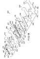
- FIG. 1is a perspective view showing a hospital bed including a base frame supported on casters, an articulating upper frame mounted on the base frame and including an upper body section, a seat section, a thigh section, and a lower leg section, a mattress supported on the articulating upper frame, a headboard, a footboard, and a pair of head-end siderails coupled to the upper body section to move between a raised patient-restraining position and a lowered storage position, and a pair of foot-end siderails coupled to the lower leg section to move between a raised patient-restraining position and a lowered storage position, and further showing two head-end siderail pads and two foot-end siderail pads in accordance with the present disclosure coupled to the respective head-end and foot-end siderails;
- FIG. 2is a view similar to FIG. 1 showing the upper body section of the articulating upper frame raised along with a corresponding portion of the mattress, the head-end siderails, and the head-end siderail pads, the configuration of the head-end siderail pads allowing articulation of the upper body section without interference therewith;
- FIG. 3is a view similar to FIG. 1 showing the siderails on one side of the bed lowered to provide access to a patient resting thereon or to facilitate patient ingress or egress, and further showing the siderail pads coupled to the siderails swung to their lowered storage position, the configuration of the head-end and foot-end siderail pads allowing lowering of one or both of the siderails without hindrance from the siderail pads;
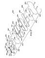
- FIG. 4is a sectional view of a portion of the hospital bed of FIGS. 1–3 showing a portion of the articulating upper frame, a portion of the mattress supported on the articulating upper frame, one of the siderails in the raised patient-restraining position, and one of the siderail pads coupled to the raised siderail and including an overhanging bolster overlying at least a portion of the mattress, the siderail pad including a lower portion extending into a gap between the siderail and the mattress, and a strap coupled to the lower edge to releasably couple the lower portion to the articulating upper frame;
- FIG. 5is a sectional view similar to FIG. 4 , with the siderail and the siderail pad shown in their respective lowered storage positions, showing the siderail pad being supported by the strap coupled to the lower edge of the siderail pad when the siderail moves to its lowered storage position;
- FIG. 6is a perspective view of one of the head-end siderail pads, as viewed from the inside or the mattress side of the hospital bed, showing a plurality of straps coupled to a lower edge of the head-end siderail pad configured to releasably couple the lower edge of the head-end siderail pad to the upper body section of the articulating upper frame, the coupling of the lower edge of the head-end siderail pad to the upper body section permitting the head-end siderail pad to swing to its lowered storage position when the head-end siderail is lowered as shown in FIGS. 3 and 5 ;
- FIG. 7is a perspective view similar to FIG. 6 of one of the foot-end siderail pads, as viewed from the mattress side, showing a plurality of straps coupled to a lower edge of the foot-end siderail pad configured to releasably couple the lower edge of the foot-end siderail pad to the lower leg section of the articulating upper frame, the coupling of the lower edge of the foot-end siderail pad to the lower leg section permitting the foot-end siderail pad to swing to its lowered storage position when the foot-end siderail is lowered as shown in FIGS. 3 and 5 ;
- FIG. 8is a perspective view of a second embodiment head-end siderail pad, as viewed from the mattress side, showing the pad including a plastic panel having an inclined portion configured to be coupled to a head-end siderail and an offset portion configured to be disposed toward a foot-end siderail, the offset portion facilitating articulation of the upper body section of the articulating upper frame without hindrance from the siderail pads, a foam layer coupled to the plastic panel on the mattress side thereof, a foam bolster having a truncated tip coupled to the foam layer, and a quick-release hinge assembly configured to releasably couple a lower edge of the plastic panel to a frame member of the upper body section of the articulating upper frame;
- FIG. 9is a perspective view of the head-end siderail pad of FIG. 8 , as viewed from the outside, showing two generally horizontal, reinforcement ribs integrally molded therewith, the hinge assembly coupled to the lower edge of the head-end siderail pad, and a plurality of slots for receiving upholstery flaps;
- FIG. 10is a perspective view of a second embodiment foot-end siderail pad, as viewed from the mattress side, showing the pad including a plastic panel having an inclined portion configured to be coupled to a foot-end siderail, a foam layer coupled to the plastic panel on the mattress side thereof, a foam bolster having a truncated tip coupled to the foam layer, and a quick-release hinge assembly configured to releasably couple a lower edge of the plastic panel to the lower leg section of the articulating upper frame;
- FIG. 11is a perspective view of the foot-end siderail pad of FIG. 10 , as viewed from the outside, showing a plurality of slots configured to receive upholstery flaps;
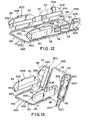
- FIG. 12is a perspective view of a hospital bed, with components removed, showing an articulating upper frame disposed in a generally horizontal position, a pair of head-end siderails (shown in phantom) movably coupled to the upper body section, a pair of foot-end siderails (shown in phantom) movably coupled to the lower leg section, a pair of head-end siderail pads of FIG. 8 coupled to the head-end siderails, and a pair of foot-end siderail pads of FIG. 10 coupled to the foot-end siderails;
- FIG. 13is a view similar to FIG. 12 showing the upper body, thigh, and lower leg sections articulated to reconfigure the posture of a patient resting in the bed, the configuration of the siderail pads allowing articulation of the upper body, thigh, and lower leg sections without hindrance therefrom;
- FIG. 14is an assembly view of a third embodiment head-end siderail pad showing the pad including a plastic panel having an inclined portion configured to be coupled to a head-end siderail, a foam layer positioned to be coupled to the plastic panel on the mattress side thereof, a foam bolster having a truncated tip positioned to be coupled to the foam layer, a quick-release hinge assembly configured to releasably couple a lower edge of the plastic panel to the upper body section of the articulating upper frame, a fire-resistant sleeve having two halves positioned to cover the plastic panel, foam layer, and bolster, and a cover having two halves positioned to cover the fire-resistant sleeve;
- FIG. 15is a side elevation view of the head-end siderail pad of FIG. 14 , with the fire-resistant sleeve and cover removed for clarity, showing the hinge assembly coupled to frame member (in phantom);
- FIG. 16is a cross-sectional view of the head-end siderail pad taken along line 16 — 16 of FIG. 15 ;
- FIG. 17is an assembly view of a third embodiment foot-end siderail pad showing the pad including a plastic panel having an inclined portion configured to be coupled to a foot-end siderail, a foam layer positioned to be coupled to the plastic panel on the mattress side thereof, a foam bolster having a truncated tip positioned to be coupled to the foam layer, a quick-release hinge assembly configured to releasably couple a lower edge of the plastic panel to the lower leg section of the articulating upper frame, a fire-resistant sleeve having two halves positioned to cover the plastic panel, foam layer, and bolster, and a cover having two halves positioned to cover the fire-resistant sleeve;
- FIG. 18is a side elevation view of the foot-end siderail pad of FIG. 17 , with the fire-resistant sleeve and cover removed for clarity, showing the hinge assembly coupled to a frame member (in phantom);
- FIG. 19is a cross-sectional view of the foot-end siderail pad taken along line 19 — 19 of FIG. 18 .
- a hospital bed or patient support 20includes a bedframe 21 including a base frame 22 supported on four casters 24 on a floor and an articulating upper frame 26 (also referred to as “articulating upper deck”) mounted on base frame 22 .
- the bed 20also includes a headboard 28 , a footboard 30 , and a mattress 32 supported on the articulating upper frame 26 .
- the articulating upper frame 26includes an upper body section 34 , a seat section 36 , a thigh section 38 , and a lower leg section 40 that are longitudinally spaced apart and transversely extending.
- the upper body, thigh, and lower leg frame sections 34 , 38 , 40are movable relative to the seat section 36 to provide for articulating movement thereof.
- the present inventionis disclosed in the context of a bed in a hospital environment, it will be understood that it is equally applicable to a bed, stretcher, gurney, wheel chair, or other patient support, in other environments—such as a patient's home, a nursing home, a convalescent home, etc.
- the articulating upper frame 26is typically mounted on an intermediate frame (not shown), which in turn is mounted on base frame 22 .
- a pair of head-end siderails 42are coupled to the upper body section 34 to move between a raised patient-restraining position shown in FIGS. 1 , 2 , and 4 and a lowered storage position shown in FIGS. 3 and 5 .
- a pair of foot-end siderails 44are coupled to the lower leg section 40 to move between a raised patient-restraining position shown in FIGS. 1 , 2 , and 4 and a lowered storage position shown in FIGS. 3 and 5 .
- Mechanisms 46 , 48are provided for lifting and lowering the head-end and foot-end siderails 42 , 44 .
- a patient resting in the hospital bed 20may inadvertently come in physical contact with the siderails 42 , 44 .
- two head-end siderail apparatus or pads 100 and two foot-end siderail apparatus or pads 200are provided to couple to the respective head-end and foot-end siderails 42 , 44 .
- the two head-end siderail pads 100are mirror images of each other. Thus, only the head-end siderail pad 100 closer to the viewer will be described herein in more detail with reference to FIGS. 4–6 .
- the head-end siderail pad or member 100includes a substantially planar support member or panel 102 made of substantially rigid material, such as hard plastic.
- the support member 102includes a first portion 104 configured to be coupled to a head-end siderail 42 and a second portion or gap filler 106 configured to extend generally downwardly, parallel to and inboard of (i.e., on the mattress side of) the head-end siderail 42 .
- the first portion 104 of the support member 102includes a hook 108 that extends over a top portion or uppermost edge 50 of the head-end siderail 42 and an extension 110 that extends generally downwardly, parallel to and outboard of the head-end siderail 42 .
- the hook 108 and the extension 110cooperate to form a slot 112 configured to releasably receive the top portion 50 of the head-end siderail 42 and couple the head-end siderail pad 100 to siderail 42 .
- other devicesare provided to couple the head-end siderail pads to the siderails.
- devicessuch as straps, vertically oriented hooks, latches, snaps, or other coupling devices known to those of ordinary skill in the art are provided.
- the second portion 106includes a first outer surface 114 facing toward the mattress 32 and a second inner surface 116 facing away from the mattress 32 .
- the first surface 114 of the second portion 106 of the support member 102exposed to the outside and likely to come in contact with a patient or an attendant, is covered with a compressible, resilient material or foam layer 118 , such as soft closed-cell foam.
- the head-end siderail pad or member 100further includes an inwardly-projecting bolster 150 coupled to the foam material 118 to couple the bolster 150 to the support member 102 .
- the bolster 150is also made from resiliently compressible material, such as soft closed-cell foam.
- the bolsteris directly coupled to the support member, the bolster and foam layer are integral, or the foam layer is not provided.
- the bolster 150is generally triangular or wedge-shaped in cross section, and has a first parallel side 152 that extends generally parallel to the first surface 114 of the support member 102 and is configured to be coupled to the foam material 118 , a second perpendicular side or lower surface 154 that extends generally perpendicularly to the first side 152 and projects over at least a portion of the mattress 32 , and a third inclined side or upper surface 156 interconnecting the first and second sides 152 , 154 of the bolster 150 .
- other shapes of bolstersare provided.
- rounded, square, curved, oval, concave, convex, or other shaped bolstersare provided having uniform or non-uniform cross-sections along their lengths.
- the head-end siderail pad 100is dimensioned such that the second perpendicular side 154 of the bolster 150 overlies a side edge portion 60 of an upwardly-facing support or patient rest surface 62 of the mattress 32 .
- the bolstereither contacts or is spaced apart from the patient rest surface of the mattress.
- the second portion 106 of the support member 102has a lower portion 120 that extends into a gap 64 defined by a side 66 of the mattress 32 and the mechanism 46 for lifting and lowering the head-end siderail 42 .
- the lower portiondoes not extend into the gap.
- a plurality of straps 122are coupled to the lower portion 120 along its lower edge 124 to releasably couple the lower edge 124 to a frame member 68 of the upper body section 34 of the articulating upper frame 26 .
- the straps 122may be formed integrally with the support member 102 .
- the straps 122may be coupled to a form-fitted, wipe-down, stain-resistant protective cover (not shown) that encases the corresponding siderail pad 100 .
- Any suitable meanssuch as VELCRO® brand hook-and-loop type fasteners 126 , buckles (not shown), or interlocking snaps (not shown), or any other fastener known to those of ordinary skill in the art, may be employed to releasably secure the straps 124 to the frame member 68 .
- other devices for releasably or permanently coupling the siderail pads to the bedare provided, such as hinges, ties, snaps, links, or other coupling devices known to those of ordinary skill in the art.
- the coupling of the lower edge 124 of the head-end siderail pad 100 to the frame member 68 of the upper body section 34permits the head-end siderail pad 100 to swing to its lowered storage position when the head-end siderail 42 is lowered as shown in FIGS. 3 and 5 .
- the head-end siderail pad 100hangs upside-down from the articulating upper deck 26 when the head-end siderail 42 is lowered to its storage position as shown in FIG. 5 .
- the head-end siderail pad 100is asymmetrical about its central vertical axis 140 .
- the head-end siderail pad 100is configured to form a window or cutout 128 for providing access to patient controls 70 mounted on the mattress side of the head-end siderail 42 .
- the head-end siderail pad or member 100has an external perimeter which is contoured to permit access to patient controls 70 .
- the head-end siderail pad 100may further include a portion 130 that extends toward the foot-end siderail 44 mounted on the same side of the bed 20 and overlaps a portion of the foot-end siderail pad 200 .
- the entire siderail pad 100may be covered with a form-fitted, wipe-down, stain-resistant protective cover (not shown), such as vinyl or nylon.
- the foot-end siderail pad or member 200is symmetrical about its central vertical axis 240 as shown in FIG. 7 so that it can be used on either side of the bed 20 .
- the foot-end siderail pad 200includes a substantially planar support member or panel 202 made of substantially rigid material, such as hard plastic.
- the support member 202includes a first portion 204 configured to be coupled to a foot-end siderail 44 and a second portion or gap filler 206 configured to extend generally downwardly, parallel to and inboard of (i.e., on the mattress side of) the foot-end siderail 44 .
- the first portion 204 of the support member 202includes a hook 208 that extends over a top portion 52 of the foot-end siderail 44 and an extension 210 that extends downwardly, generally parallel to and outboard of the foot-end siderail 44 .
- the hook 208 and the extension 210cooperate to form slot 212 configured to releasably receive the top portion or uppermost edge 52 of the foot-end siderail 44 .
- the second portion 206includes a first outer surface 214 facing toward the mattress 32 and a second inner surface 216 facing away from the mattress 32 .
- the first surface 214 of the second portion 206 of the support member 202exposed to the outside and likely to come in contact with a patient or an attendant, is covered with a compressible, resilient material or foam layer 218 , such as soft closed-cell foam.
- the foot-end siderail pad or member 200further includes an inwardly-projecting bolster 250 coupled to the foam material 218 .
- the bolster 250is also made from resiliently compressible material, such as soft closed-cell foam.
- the bolster 250is generally triangular or wedge-shaped in cross section, and has a first parallel side 252 that extends generally parallel to the first surface 214 of the support member 202 and is coupled to the foam material 218 , a second perpendicular side or lower surface 254 that extends generally perpendicularly to the first side 252 and projects over at least a portion of the mattress 32 , and a third inclined side or upper surface 256 interconnecting the first and second sides 252 , 254 of the bolster 250 .
- the foot-end siderail pad 200is dimensioned such that the second perpendicular side 254 of the bolster 250 overlies the side edge portion 60 of the upwardly-facing support surface 62 of the mattress 32 .
- the second portion 206 of the support member 202has a lower portion 220 that extends into the gap 64 between the side 66 of the mattress 32 and the mechanism 48 for lifting and lowering the foot-end siderail 44 .
- a plurality of straps 222are coupled to the lower portion 220 along its lower edge 224 for releasably securing the lower edge 224 to a frame member (not shown) of the lower leg section 40 of the articulating upper frame 26 .
- the straps 222may be formed integrally with the support member 202 .
- the straps 222may be coupled to a form-fitted, wipe-down, stain-resistant protective cover (not shown) that encases the corresponding siderail pad 200 .
- Any suitable meanssuch as VELCRO® brand hook-and-loop type fasteners 226 , buckles (not shown), or interlocking snaps (not shown), may be employed to releasably secure the straps 224 to the frame member 68 .
- the coupling of the lower edge 224 of the foot-end siderail pad 200 to the frame member 68 of the lower leg section 40permits the foot-end siderail pad 200 to swing to its lowered storage position when the foot-end siderail 44 is lowered as shown in FIGS. 3 and 5 .
- the foot-end siderail pad 200hangs upside-down from the articulating upper deck 26 when the foot-end siderail 44 is lowered to its storage position as shown in FIG. 5 .
- the entire siderail pad 200may be covered with a form-fitted, wipe-down, stain-resistant protective cover (not shown), such as vinyl or nylon.
- the hook 108couples the remainder of the siderail pad 100 to the siderail 42 .
- the siderail 42is moved to the lowered position, it “clocks” or rotates about a transverse axis 43 .
- the bolster 150blocks downward movement of the siderail pad 100 with the siderail 42 .
- the upper portion 50 of the siderail 42drops out of the slot 112 so that the siderail pad 100 is no longer coupled to the siderail 42 .
- the lower portion 120 of the siderail pad 100is no longer trapped between the mechanism 46 and the side 66 of the mattress 32 .
- Gravity, a caregiver, or the patientcause the siderail 100 to rotate in direction 111 to the position shown in FIG. 5 .
- the siderail pad 100was positioned on the inner side of the siderail 42 and after the siderail 42 is dropped, the siderail pad 100 rotates down so that it is positioned on the outer side of the siderail 42 .
- a caregiverTo raise the siderail 42 , a caregiver first flips or rotates the siderail pad 100 in direction 113 so that the lower surface 154 of the bolster 150 again overlays or rests on the patient rest surface 62 . Then the siderail 42 is clocked about the transverse axis 43 to the raised position. As the head-end siderail 42 approaches the raised position, the uppermost edge 50 of the head-end siderail 42 is again positioned in the slot 112 and the siderail pad 100 is again coupled to the siderail 42 . The foot-end siderail 44 is similarly lowered and raised relative to the bedframe 11 and the siderail pad 200 .
- the siderail padsare used with other configurations of siderails, such as siderails that are raised and lowered about a longitudinal axis, siderails that are raised and lowered in a substantially vertical plane defined by the siderail, siderails that do not move relative to the bedframe, or any other siderails known to those or ordinary skill in the art.
- FIGS. 8 and 9illustrate a second embodiment head-end siderail pad or apparatus 300 .
- FIGS. 10 and 11illustrate a second embodiment foot-end siderail pad or apparatus 400 .
- the construction of the second embodiment of the head-end and foot-end siderail pads or members 300 , 400is generally similar to the construction of the first embodiments of the head-end and foot-end siderail pads or members 100 , 200 .
- like components in various figuresare identified by like numerals.
- the bolster in the first embodiment of the head-end siderail pad 100is identified by the numeral 150
- the bolster in the second embodiment of the head-end siderail pad 300is identified by the numeral 350 .
- the head-end siderail pad 300includes a support member or panel 302 made of substantially rigid material, such as hard plastic.
- the support member 302includes a first inclined portion 304 configured to extend generally downwardly, at an angle to and inboard of the head-end siderail 42 , and a second parallel portion or gap filler 306 configured to extend generally downwardly, parallel to and inboard of the head-end siderail 42 .
- the first inclined portion 304is configured to be coupled to the head-end siderail 42 , and includes a hook 308 that extends over the top portion 50 of the head-end siderail 42 and an extension 310 that extends generally downwardly, parallel to and outboard of the head-end siderail 42 .
- the hook 308 and extension 310cooperate to form a slot 312 configured to releasably receive the top portion 50 of the head-end siderail 42 .
- the first inclined portion 304 and the second parallel portion 306include a first outer surface 314 facing toward the mattress 32 and a second inner surface 316 facing away from the mattress 32 .
- the first surface 314 of the first and second portions 304 , 306 of the support member 302exposed to the outside and likely to come in contact with a patient or an attendant, is covered with a compressible, resilient material or foam layer 318 , such as soft closed-cell foam.
- the head-end siderail pad 300further includes an inwardly-projecting, truncated-tip bolster 350 coupled to the foam material 318 .
- the bolster 350is also made from resiliently compressible material, such as soft closed-cell foam.
- the truncated-tip bolster 350is generally trapezoidal or wedge-shaped in cross section, and has a first parallel side 352 that extends generally parallel to the first surface 314 of the second portion 306 of the support member 302 and is coupled to the foam material 318 , a second perpendicular side or lower surface 354 that extends generally perpendicular to the first side 352 and projects over at least a portion of the mattress 32 , a third truncated side or surface 356 that extends generally parallel to and spaced from the first side 352 , and a fourth inclined side or upper surface 358 interconnecting the first and third sides 352 , 354 of the bolster 350 .
- the head-end siderail pad 300is dimensioned such that the second perpendicular side 354 of the truncated-tip bolster 350 overlies the side edge portion 60 of the upwardly-facing support surface 62 of the mattress 32 .
- the second portion 306 of the support member 302has a lower portion 320 that extends into the gap 64 between the side 66 of the mattress 32 and the mechanism 46 for lifting and lowering the head-end siderail 42 .
- a quick-release hinge assembly 360is provided for releasably attaching a lower edge 324 of the support member 302 to the frame member 68 of the upper body section 34 of the articulating upper frame 26 .
- the quick-release hinge assembly 360includes a first hinge half 362 coupled to the lower edge 324 of the support member 302 and a second hinge half 364 coupled to an elongated strip 366 .
- the elongated strip 366is, in turn, coupled to the frame member 68 of the upper body section 34 of the articulating upper frame 26 by means of screws (not shown).
- the configuration of the two hinge halves 362 , 364permits quick coupling and uncoupling of the head-end siderail pad 300 to the frame member 68 of the upper body section 34 .
- the hinge assembly 360includes two vertical posts 368 which are squeezed together to release the head-end siderail pad 300 from the frame member 68 .
- the attachment of the lower edge 324 of the head-end siderail pad 300 to the frame member 68 of the upper body section 34permits the head-end siderail pad 300 to swing to its lowered storage position when the head-end siderail 42 is lowered.
- the hinge assembly 360the head-end siderail pad 300 hangs upside-down from the articulating upper deck 26 when the head-end siderail 42 is lowered to its storage position.
- the head-end siderail pad 300is asymmetrical about its central vertical axis 340 .
- the head-end siderail pad or member 300is configured to form a window or cutout 328 for providing access to the patient controls 70 mounted on the mattress side of the head-end siderail 42 .
- the head-end siderail pad or member 300has an external perimeter which is contoured to permit access to patient controls 70 .
- the head-end siderail pad 300further includes an offset portion 330 that extends toward the foot-end siderail 44 mounted on the same side of the bed 20 and overlaps a portion of the foot-end siderail pad 400 .
- the offset portion 330permits articulation of the bed 20 without hindrance from the siderail pad 300 .
- Two generally horizontal reinforcement ribs 334are integrally molded on the side of the second portion 306 facing away from the mattress 32 .
- the entire siderail pad 300may be encased in a form-fitted, wipe-down, stain-resistant protective cover (not shown), such as vinyl or nylon.
- a plurality of slots 336are provided for attaching upholstery flaps (not shown) of the protective cover to aid in preventing sagging of the protective cover.
- the foot-end siderail pad or member 400is, on the other hand, symmetrical about its central vertical axis 440 as shown in FIGS. 10 and 11 so that it can be used on either side of the bed 20 .
- the foot-end siderail pad 400includes a support member or panel 402 made of substantially rigid material, such as hard plastic.
- the support member 402includes a first inclined portion 404 configured to extend generally downwardly, at an angle to and inboard of the foot-end siderail 44 , and a second parallel portion or gap filler 406 configured to extend generally downwardly, parallel to and inboard of the foot-end siderail 44 .
- the first inclined portion 404is configured to be coupled to the foot-end siderail 44 , and includes a hook 408 that extends over the top portion 52 of the foot-end siderail 44 and an extension 410 that extends generally downwardly, parallel to and outboard of the foot-end siderail 44 .
- the hook 408 and extension 410cooperate to form a slot 412 configured to releasably receive the top portion 52 of the foot-end siderail 44 .
- the first inclined portion 404 and the second parallel portion 406include a first outer surface 414 facing toward the mattress 32 and a second inner surface 416 facing away from the mattress 32 .
- the first surface 414 of the first and second portions 404 , 406 of the support member 402exposed to the outside and likely to come in contact with a patient or an attendant, is covered with a compressible, resilient material or foam layer 418 , such as soft closed-cell foam.
- the foot-end siderail pad 400further includes an inwardly-projecting, truncated-tip bolster 450 coupled to the foam material 418 .
- the bolster 450is also made from resiliently compressible material, such as soft closed-cell foam.
- the truncated-tip bolster 450is generally trapezoidal or wedge-shaped in cross section, and has a first parallel side 452 that extends generally parallel to the first surface 414 of the second portion 406 of the support member 402 and is coupled to the foam material 418 , a second perpendicular side or lower surface 454 that extends generally perpendicular to the first side 452 and projects over at least a portion of the mattress 32 , a third truncated side or surface 456 that extends generally parallel to and spaced from the first side 452 , and a fourth inclined side or upper surface 458 interconnecting the first and third sides 452 , 454 of the bolster 450 .
- the foot-end siderail pad 400is dimensioned such that the second perpendicular side 454 of the truncated-tip bolster 450 overlies the side edge portion 60 of the upwardly-facing support surface 62 of the mattress 32 .
- the second portion 406 of the support member 402has a lower portion 420 that extends into the gap 64 between the side 66 of the mattress 32 and the mechanism 48 for lifting and lowering the foot-end siderail 44 .
- a quick-release hinge assembly 460is provided to releasably couple a lower edge 424 of the support member 402 to a frame member (not shown) of the lower leg section 40 of the articulating upper frame 26 .
- the quick-release hinge assembly 460includes a first hinge half 462 coupled to the lower edge 424 of the support member 402 and a second hinge half 464 coupled to an elongated strip 466 .
- the elongated strip 466is, in turn, coupled to the frame member of the lower leg section 40 of the articulating upper frame 26 by means of screws (not shown).
- the configuration of the two hinge halves 462 , 464permits quick coupling and uncoupling of the foot-end siderail pad 400 to the frame member of the lower leg section 40 .
- the hinge assembly 460includes two vertical posts 468 which are squeezed together to release the foot-end siderail pad 400 from the frame member.
- the attachment of the lower edge 424 of the foot-end siderail pad 400 to the frame member of the lower leg section 40permits the foot-end siderail pad 400 to swing to its lowered storage position when the foot-end siderail 44 is lowered.
- the hinge assembly 460the foot-end siderail pad 400 hangs upside-down from the articulating upper deck 26 when the foot-end siderail 44 is lowered to its storage position.
- the entire siderail pad 400may be encased in a form-fitted, wipe-down, stain-resistant protective cover (not shown), such as vinyl or nylon.
- a plurality of slots 436are provided for attaching upholstery flaps (not shown) of the protective cover.
- FIG. 12is a perspective view showing the head-end and foot-end siderail pads 300 , 400 coupled to the head-end and foot-end siderails 42 , 44 while the articulating upper frame 26 is generally flat.
- FIG. 13is a perspective view showing the head-end and foot-end siderail pads 300 , 400 coupled to the head-end and foot-end siderails 42 , 44 while the upper body, thigh, and lower leg sections 34 , 38 , 40 are articulated with respect to the seat section 36 .
- the configuration of the siderail pads 300 , 400allows articulation of the bed 20 and lifting and lowering of the siderails 42 and 44 without hindrance from the siderail pads 300 , 400 .
- FIGS. 14–16illustrate a third embodiment head-end siderail pad or apparatus 500 .
- FIGS. 17–19illustrate a third embodiment foot-end siderail pad or apparatus 600 .
- the construction of the third embodiment of the head-end and foot-end siderail pads or members 500 , 600is generally similar to the construction of the first embodiments of the head-end and foot-end siderail pads 100 , 200 .
- like components in various figuresare identified by like numerals.
- the bolster in the first embodiment of the head-end siderail pad 100is identified by the numeral 150
- the bolster in the third embodiment of the head-end siderail pad 500is identified by the numeral 550 .
- the head-end siderail pad or member 500includes a support member or panel 502 made of substantially rigid material, such as hard plastic.
- the support member 502includes a first inclined portion 504 configured to extend generally downwardly, at an angle to and inboard of the head-end siderail 42 , a second parallel portion or gap filler 506 configured to extend generally downwardly, parallel to and inboard of the head-end siderail 42 , and a third inclined portion 507 configured to extend generally upward from the second portion 506 at an angle to and inboard of the head-end siderail 42 .
- the first inclined portion 504is configured to be coupled to the head-end siderail 42 , and includes a hook 508 that extends over the top portion 50 of the head-end siderail 42 and an extension 510 that extends generally downwardly, parallel to and outboard of the head-end siderail 42 .
- the hook 508 and extension 510cooperate to form a slot 512 configured to releasably receive the top portion 50 of the head-end siderail 42 .
- the first inclined portion 504 , the second parallel portion 506 , and the third inclined portion 507include a first outer surface 514 facing toward the mattress 32 and a second inner surface 516 facing away from the mattress 32 .
- the first surface 514 of the first, second, and third portions 504 , 506 , 507 of the support member 502exposed to the outside and likely to come in contact with a patient or an attendant, is covered with a compressible, resilient material or foam layer 518 , such as soft closed-cell foam.
- Resilient material 518is coupled to support member 502 by a layer of adhesive.
- the head-end siderail pad 500further includes an inwardly-projecting, truncated-tip bolster 550 coupled to the foam material 518 by a layer of spray-on adhesive.
- the bolster 550is also made from resiliently compressible material, such as soft closed-cell foam. As shown in FIG.
- the truncated-tip bolster 550is generally trapezoidal or wedge-shaped in cross section, and has a first parallel side 552 that extends generally parallel to the first surface 514 of the second portion 506 of the support member 502 and is coupled to the foam material 518 , a second perpendicular side or lower surface 554 that extends generally perpendicular to the first side 552 and projects over at least a portion of the mattress 32 , a third truncated side or surface 556 that extends generally parallel to and spaced from the first side 552 , and a fourth inclined side or upper surface 558 interconnecting the first and third sides 552 , 556 of the bolster 550 .
- the head-end siderail pad 500is dimensioned such that the second perpendicular side 554 of the truncated-tip bolster 550 overlies the side edge portion 60 of the upwardly-facing support surface 62 of the mattress 32 .
- the second portion 506 of the support member 502has a lower portion 520 that extends into the gap 64 between the side 66 of the mattress 32 and the mechanism 46 for lifting and lowering the head-end siderail 42 .
- the siderail pad 500further includes a fire-resistant sleeve 538 having first and second halves 542 , 544 .
- the first and second halves 542 , 544are sewn together along the respective upper and side edges to form a pocket having an opening defined by the lower edges of the first and second halves 542 , 544 .
- the assembled support member 502 , resilient material 518 , and bolster 550are then positioned in the sleeve 538 through the opening and the lower edges are sewn together using fiberglass thread to encase the support member 502 , resilient material 518 , and bolster 550 within the sleeve 538 .
- the halves 542 , 544are preferably made of KEVLAR® brand fire-resistant material. According to alternative embodiments of the present disclosure, other fire-resistant or fire proof materials are used for the sleeve.
- the siderail pad 500further includes a cover 570 having first and second halves 572 , 574 positioned to cover the fire-resistant sleeve 538 .
- the halves 572 , 574are made of a wipeable, stain-resistant material such as vinyl or nylon.
- the first and second halves 572 , 574are sewn together along the perimeter edges.
- the second half 574includes a zipper 576 defining a slit through which the assembled sleeve 538 , support member 502 , resilient material 518 , and bolster 550 are inserted.
- the second half 574further includes a plurality of upholstery flaps or straps 578 having hook and loop fasteners 579 thereon that are feed through a plurality of slots 536 formed in the sleeve 538 , support member 502 , and resilient material 518 .
- the straps 578are fed through buckles (not shown) coupled to the first half 572 to pull first half 572 of cover 570 and first half 542 of sleeve 538 against resilient material 518 to prevent sagging of the cover 570 .
- other devices for coupling the first half of the cover to the resilient materialare provided such as hooks, buttons, snaps, or other fasteners.
- the zipper 576is closed to encase the assembled fire-resistant sleeve 538 , support member 502 , resilient material 518 , and bolster 550 in the cover 570 .
- a flap(not shown) having hook and loop fasteners is also provided to cover the pull of the zipper 576 after the zipper 576 is closed.
- the flapalso provides an extension of the slit defined by the zipper 576 to facilitate insertion of the assembled sleeve 538 , support member 502 , and resilient material 518 into the cover 570 .
- a quick-release hinge assembly 560is provided for releasably attaching a lower edge 524 of the support member 502 to the upper body section 34 of the articulating upper frame 26 .
- the quick-release hinge assembly 560includes a first pair of hinge halves 562 coupled to the lower edge 524 of the support member 502 by fasteners 559 and a second pair of hinge halves 564 coupled to an elongated strip 566 .
- the elongated strip 566is, in turn, coupled to upper body section 34 of the articulating upper frame 26 by a hook 567 and a latch 569 pivotably coupled to the elongated strip 566 and biased by a spring 571 .
- the latch 569 and spring 571are configured to slide longitudinally along elongated strip 566 to permit use of the same hinge assembly 560 on each of the four head and foot-end siderail pads 500 , 600 .
- upper body section 34includes an L-shaped frame member 561 including a vertical portion 563 and a horizontal portion 565 .
- the hook 567 of elongated strip 566is positioned around the vertical portion 563 of the frame member 561 while the latch 569 is depressed against the bias of the spring 571 .
- the latch 569is released so that the latch 569 is positioned around the horizontal portion 565 of the frame member 561 to trap the frame member 561 between the hook 567 and latch 569 as shown in FIG. 16 .
- the head-end siderail pad 500hangs upside-down from the articulating upper deck 26 when the head-end siderail 42 is lowered to its storage position.
- the head-end siderail pad 500is asymmetrical about its central vertical axis 540 .
- the head-end siderail pad or member 500is configured to form a window or cutout 528 for providing access to the patient controls 70 mounted on the mattress side of the head-end siderail 42 .
- the head-end siderail pad or member 500has an external perimeter which is contoured to permit access to patient controls 70 .
- the head-end siderail pad 500further includes an offset portion 530 that extends toward the foot-end siderail 44 mounted on the same side of the bed 20 and overlaps a portion of the foot-end siderail pad 600 .
- the offset portion 530permits articulation of the bed 20 without hindrance from the siderail pad 500 .
- Two generally horizontal reinforcement ribs 534are integrally molded on the side of the second portion 506 facing away from the mattress 32 .
- the foot-end siderail pad 600is, on the other hand, symmetrical about its central vertical axis 640 , as shown in FIG. 18 , so that it can be used on either side of the bed 20 .
- the foot-end siderail pad 600includes a support member or panel 602 made of substantially rigid material, such as hard plastic as shown in FIG. 17 .
- the support member 602includes a first inclined portion 604 configured to extend generally downwardly, at an angle to and inboard of the foot-end siderail 44 , and a second parallel portion or gap filler 606 configured to extend generally downwardly, parallel to and inboard of the foot-end siderail 44 .
- the first inclined portion 604is configured to be coupled to the foot-end siderail 44 , and includes a hook 608 that extends over the top portion 52 of the foot-end siderail 44 and an extension 610 that extends generally downwardly, parallel to and outboard of the foot-end siderail 44 .
- the hook 608 and extension 610cooperate to form a slot 612 configured to releasably receive the top portion 52 of the foot-end siderail 44 .
- the first inclined portion 604 and the second parallel portion 606include a first outer surface 614 facing toward the mattress 32 and a second inner surface 616 facing away from the mattress 32 .
- the first surface 614 of the first and second portions 604 , 606 of the support member 602exposed to the outside and likely to come in contact with a patient or an attendant, is covered with a compressible, resilient material or foam layer 618 , such as soft closed-cell foam.
- the foot-end siderail pad 600further includes an inwardly-projecting, truncated-tip bolster 650 coupled to the foam material 618 .
- the bolster 650is also made from resiliently compressible material, such as soft closed-cell foam.
- the truncated-tip bolster 650is generally trapezoidal or wedge-shaped in cross section, and has a first parallel side 652 that extends generally parallel to the first surface 614 of the second portion 606 of the support member 602 and is coupled to the foam material 618 , a second perpendicular side or lower surface 654 that extends generally perpendicular to the first side 652 and projects over at least a portion of the mattress 32 , a third truncated side 656 that extends generally parallel to and spaced from the first side 652 , and a fourth inclined side or upper surface 658 interconnecting the first and third sides 652 , 654 of the bolster 650 .
- the foot-end siderail pad 600is dimensioned such that the second perpendicular side 654 of the truncated-tip bolster 650 overlies the side edge portion 60 of the upwardly-facing support surface 62 of the mattress 32 .
- the second portion 606 of the support member 602has a lower portion 620 that extends into the gap 64 between the side 66 of the mattress 32 and the mechanism 48 for lifting and lowering the foot-end siderail 44 .
- the siderail pad 600further includes a fire-resistant sleeve 638 having first and second halves 642 , 644 .
- the first and second halves 642 , 644are sewn together along the respective upper and side edges to form a pocket having an opening defined by the lower edges of the first and second halves 642 , 644 .
- the assembled support member 602 , resilient material 618 , and bolster 650are then positioned in the sleeve 638 through the opening and the lower edges are sewn together using fiberglass thread to encase the support member 602 , resilient material 618 , and bolster 650 within the sleeve 638 .
- the halves 642 , 644are preferably made of KEVLAR® brand fire-resistant material.
- the siderail pad 600further includes a cover 670 having first and second halves 672 , 674 positioned to cover the fire-resistant sleeve 638 .
- the halves 672 , 674are made of a wipeable, stain-resistant material such as vinyl or nylon.
- the first and second halves 672 , 674are sewn together along the perimeter edges.
- the second half 674includes a zipper 676 defining a slit through which the assembled sleeve 638 , support member 602 , resilient material 618 , and bolster 650 are inserted.
- the second half 674further includes a plurality of upholstery flaps or straps 678 having hook and loop fasteners 679 thereon that are feed through a plurality of slots 636 formed in the sleeve 638 , support member 602 , and resilient material 618 .
- the straps 678are fed through buckles (not shown) coupled to the first half 672 to pull first half 672 of cover 670 and first half 642 of sleeve 638 against resilient material 618 to prevent sagging of the cover 670 .
- the zipper 676is closed to encase the assembled fire-resistant sleeve 638 , support member 602 , resilient material 618 , and bolster 650 in the cover 670 .
- a flap(not shown) having hook and loop fasteners is also provided to cover the pull of the zipper 676 after the zipper 676 is closed.
- the flapalso provides an extension of the slit defined by the zipper 676 to facilitate insertion of the assembled sleeve 638 , support member 602 , and resilient material 618 into the cover 670 .
- FIG. 17another quick-release hinge assembly 560 is provided for releasably attaching a lower edge 624 of the support member 602 to the lower leg section 40 of the articulating upper frame 26 .
- the configuration of the hook 567 and latch 569permits quick coupling and uncoupling of the foot-end siderail pad 600 to the lower leg section 40 .
- lower leg section 40includes an L-shaped frame member 661 including a vertical portion 663 and a horizontal portion 665 .
- the hook 567 of elongated strip 566is positioned around the vertical portion 663 of the frame member 661 while the latch 569 is depressed against the bias of the spring 571 .
- the latch 569is released so that the latch 569 is positioned around the horizontal portion 665 of the frame member 661 to trap the frame member 661 between the hook 567 and latch 569 as shown in FIG. 19 .
- the hinge assembly 560the foot-end siderail pad 600 hangs upside-down from the articulating upper deck 26 when the foot-end siderail 44 is lowered to its storage position.
- the siderail pads or members 100 , 200 , 300 , 400 , 500 , 600provide soft padding 118 , 218 , 318 , 418 , 518 , 618 around the siderails 42 , 44 to prevent injury to a patient or a caregiver.
- the bolsters 150 , 250 , 350 , 450 , 550 , 650close the gap between the siderails 42 , 44 and the mattress 32 or the gap within siderails 42 , 44 , or between adjacent split siderails 42 , 44 , or between the headboard 28 or the footboard 30 and an adjoining siderail 42 , 44 .
- the outer protective coversallow easy cleaning of the siderail pads 100 , 200 , 300 , 400 , 500 , 600 .
- the support members 102 , 202 , 302 , 402 , 502 , 602are molded from relatively rigid plastic, such as ABS
- the foam coatings 118 , 218 , 318 , 418 , 518 , 618are made from materials such as closed-cell polyurethane foam
- the bolsters 150 , 250 , 350 , 450 , 550 , 650are made from soft foam material, such as polyurethane foam
- the outer protective coverslike that shown for head and foot-end siderail pads 500 , 600 encasing the siderail pads 100 , 200 , 300 , 400 , 500 , 600 are made from wipe-down, stain-resistant material, such as vinyl or nylon.
Landscapes
- Health & Medical Sciences (AREA)
- Nursing (AREA)
- Life Sciences & Earth Sciences (AREA)
- Animal Behavior & Ethology (AREA)
- General Health & Medical Sciences (AREA)
- Public Health (AREA)
- Veterinary Medicine (AREA)
- Invalid Beds And Related Equipment (AREA)
Abstract
Description
Claims (27)
Priority Applications (1)
| Application Number | Priority Date | Filing Date | Title |
|---|---|---|---|
| US10/627,226US6928673B2 (en) | 1999-10-15 | 2003-07-25 | Siderail pad for hospital bed |
Applications Claiming Priority (3)
| Application Number | Priority Date | Filing Date | Title |
|---|---|---|---|
| US15980399P | 1999-10-15 | 1999-10-15 | |
| US09/687,715US6615426B1 (en) | 1999-10-15 | 2000-10-13 | Siderail pad for hospital bed |
| US10/627,226US6928673B2 (en) | 1999-10-15 | 2003-07-25 | Siderail pad for hospital bed |
Related Parent Applications (1)
| Application Number | Title | Priority Date | Filing Date |
|---|---|---|---|
| US09/687,715ContinuationUS6615426B1 (en) | 1999-10-15 | 2000-10-13 | Siderail pad for hospital bed |
Publications (2)
| Publication Number | Publication Date |
|---|---|
| US20050071921A1 US20050071921A1 (en) | 2005-04-07 |
| US6928673B2true US6928673B2 (en) | 2005-08-16 |
Family
ID=22574099
Family Applications (2)
| Application Number | Title | Priority Date | Filing Date |
|---|---|---|---|
| US09/687,715Expired - Fee RelatedUS6615426B1 (en) | 1999-10-15 | 2000-10-13 | Siderail pad for hospital bed |
| US10/627,226Expired - LifetimeUS6928673B2 (en) | 1999-10-15 | 2003-07-25 | Siderail pad for hospital bed |
Family Applications Before (1)
| Application Number | Title | Priority Date | Filing Date |
|---|---|---|---|
| US09/687,715Expired - Fee RelatedUS6615426B1 (en) | 1999-10-15 | 2000-10-13 | Siderail pad for hospital bed |
Country Status (7)
| Country | Link |
|---|---|
| US (2) | US6615426B1 (en) |
| EP (1) | EP1229882A1 (en) |
| JP (1) | JP2003511209A (en) |
| AU (1) | AU1205201A (en) |
| BR (1) | BR0014784A (en) |
| CA (1) | CA2388501A1 (en) |
| WO (1) | WO2001028483A1 (en) |
Cited By (43)
| Publication number | Priority date | Publication date | Assignee | Title |
|---|---|---|---|---|
| GB2430614A (en)* | 2005-09-29 | 2007-04-04 | Proto Magic Innovations Ltd | A grab rail/cot side for a mattress elevator |
| US20080092294A1 (en)* | 2006-09-14 | 2008-04-24 | Rawls-Meehan Martin B | Methods and systems of an adjustable bed |
| USD572490S1 (en) | 2006-06-05 | 2008-07-08 | Steelcase Inc. | Chair |
| USD572914S1 (en) | 2006-06-05 | 2008-07-15 | Steelcase Inc. | Chair |
| US20090049614A1 (en)* | 2007-08-23 | 2009-02-26 | Justin Long | System and method to occlude patient entrapment zones |
| US20090144908A1 (en)* | 2007-12-10 | 2009-06-11 | Justin Long | System and method to occlude patient entrapment zones |
| US20090229050A1 (en)* | 2008-03-13 | 2009-09-17 | Hill-Rom Services, Inc. | Siderail gap filler |
| US7644991B2 (en) | 2006-06-02 | 2010-01-12 | Steelcase Inc. | Chair with folding armrest |
| US7676862B2 (en) | 2004-09-13 | 2010-03-16 | Kreg Medical, Inc. | Siderail for hospital bed |
| US7743441B2 (en) | 2004-09-13 | 2010-06-29 | Kreg Therapeutics, Inc. | Expandable width bed |
| US7757318B2 (en) | 2004-09-13 | 2010-07-20 | Kreg Therapeutics, Inc. | Mattress for a hospital bed |
| US7779494B2 (en) | 2004-09-13 | 2010-08-24 | Kreg Therapeutics, Inc. | Bed having fixed length foot deck |
| US7784123B2 (en) | 2007-08-23 | 2010-08-31 | Kci Licensing, Inc. | System and method to occlude patient entrapment zones |
| US20100287702A1 (en)* | 2009-01-12 | 2010-11-18 | Jin Rie | Comfortable bed preventing bed sores for invalids and sleep disturbing patient |
| US20110232001A1 (en)* | 2008-06-27 | 2011-09-29 | Craig Poulos | Bed gap filler |
| US20110247138A1 (en)* | 2010-04-12 | 2011-10-13 | Ergomotion, Inc. | Bed frame for an adjustable bed |
| US8069512B2 (en)* | 2006-09-14 | 2011-12-06 | Martin B Rawls-Meehan | Adjustable bed frame |
| US8100061B2 (en) | 2008-06-13 | 2012-01-24 | Hill-Rom Services, Inc. | Item support apparatuses and systems for bedside |
| US8239986B2 (en) | 2008-03-13 | 2012-08-14 | Hill-Rom Services, Inc. | Siderail assembly for a patient-support apparatus |
| US8341778B2 (en) | 2011-02-07 | 2013-01-01 | Hill-Rom Services, Inc. | Bed gap filler and footboard pad |
| US8539625B2 (en) | 2009-09-23 | 2013-09-24 | Kreg Medical Inc. | Bed gap shield |
| WO2014116779A1 (en)* | 2013-01-24 | 2014-07-31 | Ergomotion, Inc. | Bolster attachment system for an adjustable bed |
| US8909357B2 (en) | 2007-09-14 | 2014-12-09 | Martin B Rawls-Meehan | System for tandem bed communication |
| US8909378B2 (en) | 2006-09-14 | 2014-12-09 | Martin B Rawls-Meehan | Adjustable bed position control |
| US8926535B2 (en) | 2006-09-14 | 2015-01-06 | Martin B. Rawls-Meehan | Adjustable bed position control |
| US9044365B2 (en) | 2006-09-14 | 2015-06-02 | Ascion, Llc | Mattress support facility with retaining brackets |
| USD733452S1 (en) | 2010-02-09 | 2015-07-07 | Ascion, Llc | Adjustable bed |
| USD736023S1 (en) | 2013-01-25 | 2015-08-11 | Ascion, Llc | Adjustable bed |
| US9119753B2 (en) | 2008-06-27 | 2015-09-01 | Kreg Medical, Inc. | Bed with modified foot deck |
| US9173793B2 (en) | 2006-09-14 | 2015-11-03 | Ascion, Llc | Adjustable bed frame with mattress retaining brackets |
| US9259371B2 (en) | 2009-07-15 | 2016-02-16 | Hill-Rom Services, Inc. | Siderail with storage area |
| US9433546B2 (en) | 2006-09-14 | 2016-09-06 | Ascion, Llc | Dual motion deck-on-deck bed frame |
| US9629473B2 (en) | 2009-02-09 | 2017-04-25 | Ascion, Llc | Leg assembly |
| US10064784B2 (en) | 2006-09-14 | 2018-09-04 | Martin B. Rawls-Meehan | System and method of an adjustable bed with a vibration motor |
| US10864137B2 (en) | 2006-09-14 | 2020-12-15 | Ascion, Llc | System and method of an adjustable bed with a vibration motor |
| US10874574B1 (en) | 2018-02-27 | 2020-12-29 | Krug Inc. | Patient examination system |
| US11052005B2 (en) | 2017-09-19 | 2021-07-06 | Stryker Corporation | Patient support apparatus with handles for patient ambulation |
| US11116680B2 (en) | 2017-09-19 | 2021-09-14 | Stryker Corporation | Patient support apparatus for controlling patient ingress and egress |
| US11134787B2 (en) | 2018-05-16 | 2021-10-05 | Bestar Inc. | Anti-shearing and anti-crushing device on a retractable bed |
| US11160705B2 (en) | 2017-10-20 | 2021-11-02 | Stryker Corporation | Adjustable patient support apparatus for assisted egress and ingress |
| US11426128B1 (en) | 2018-02-27 | 2022-08-30 | Krug Inc. | Patient examination system |
| US11918517B2 (en) | 2021-10-07 | 2024-03-05 | Stryker Corporation | Cover systems for blocking apertures of patient support apparatuses |
| US12150908B2 (en) | 2014-04-18 | 2024-11-26 | Kreg Medical, Inc. | Patient support with stand-up and sit features |
Families Citing this family (25)
| Publication number | Priority date | Publication date | Assignee | Title |
|---|---|---|---|---|
| US6427264B1 (en) | 1999-03-19 | 2002-08-06 | Hill-Rom Services, Inc. | Gap filler for bed |
| US6615426B1 (en)* | 1999-10-15 | 2003-09-09 | Hill-Rom Services, Inc. | Siderail pad for hospital bed |
| DE60229868D1 (en) | 2001-08-22 | 2008-12-24 | Hill Rom Services Inc | DEVICE AND METHOD FOR CLOSING GASES IN HOSPITAL BEDS |
| US7100222B2 (en) | 2001-08-22 | 2006-09-05 | Hill-Rom Services, Inc. | Apparatus and method for mounting hospital bed accessories |
| US7073220B2 (en) | 2002-09-06 | 2006-07-11 | Hill-Rom Services, Inc. | Bed siderail having a latch |
| US6820293B2 (en)* | 2002-09-26 | 2004-11-23 | Hill-Rom Services, Inc. | Bed siderail pad apparatus |
| US7028353B2 (en)* | 2003-01-14 | 2006-04-18 | Simplicity, Inc. | Adjustable bed rail |
| US6721975B1 (en)* | 2003-05-09 | 2004-04-20 | Stryker Corporation | Overlapping siderail assembly for bed |
| RU2268698C2 (en)* | 2003-09-24 | 2006-01-27 | Илья Львович Царев | Functional bed with guarding members and retainer for guarding members |
| US7231678B2 (en)* | 2004-02-06 | 2007-06-19 | Kci Licensing, Inc. | Side rail pad system for patient support apparatus |
| JP4712793B2 (en) | 2004-03-12 | 2011-06-29 | ヒル−ロム サービシーズ,インコーポレイティド | Adjustable high side rail for bed |
| JP4663269B2 (en)* | 2004-07-30 | 2011-04-06 | 酒井医療株式会社 | stretcher |
| JP4509694B2 (en)* | 2004-08-23 | 2010-07-21 | パラマウントベッド株式会社 | Foldable side rail cover |
| US7559101B2 (en)* | 2005-02-16 | 2009-07-14 | Kci Licensing, Inc. | Side rail pad/panel system for patient support apparatus |
| JP2006326172A (en)* | 2005-05-30 | 2006-12-07 | Sankei Giken:Kk | Reclining chair |
| US8104122B2 (en) | 2005-12-19 | 2012-01-31 | Hill-Rom Services, Inc. | Patient support having an extendable foot section |
| EP2556811A1 (en) | 2006-02-08 | 2013-02-13 | Hill-Rom Services, Inc. | End panel for a patient-support apparatus |
| US7850595B2 (en)* | 2007-01-08 | 2010-12-14 | White Robert D | Transferring and holding device for high-risk neonatal intensive care unit (NICU) patients |
| US7774874B2 (en)* | 2007-08-01 | 2010-08-17 | Margaret Webb Pressler | Crib bumper |
| US7930778B2 (en)* | 2007-12-07 | 2011-04-26 | Hill-Rom Services, Inc. | Pinch-preventing unit for bed guardrail |
| US20120011651A1 (en)* | 2010-07-14 | 2012-01-19 | Dan Moss | Inflatable Mattress Guard |
| US9131784B2 (en)* | 2012-08-28 | 2015-09-15 | Suki Moon Llc | Crib/cradle sleep system |
| US9138365B2 (en)* | 2013-06-26 | 2015-09-22 | Kenneth A. Deese | Patient protective system for an adjustable bed |
| US10426680B2 (en) | 2015-07-31 | 2019-10-01 | Hill-Rom Services, Inc. | Air bladder control of mattress/frame width expansion |
| US20240139050A1 (en)* | 2022-10-27 | 2024-05-02 | Stryker Corporation | Patient Support Apparatus Having A Skirt Barrier |
Citations (184)
| Publication number | Priority date | Publication date | Assignee | Title |
|---|---|---|---|---|
| US421656A (en) | 1890-02-18 | Removable siding for beds | ||
| US993119A (en) | 1910-04-22 | 1911-05-23 | Percival D Stannard | Footboard-quilt. |
| US1398203A (en) | 1921-02-19 | 1921-11-22 | Henry A Schmidt | Convertible bed-spring |
| US2136088A (en) | 1937-08-17 | 1938-11-08 | Frank A Hall & Sons | Bed attachment |
| US2164484A (en) | 1937-03-10 | 1939-07-04 | Joseph A Wolfe | Detachable side panel for beds |
| US2254466A (en) | 1938-04-15 | 1941-09-02 | Albert Lisa | High-chair pad |
| US2281209A (en) | 1938-07-29 | 1942-04-28 | Smith Orville Dale | Combination bed and carriage |
| US2452366A (en) | 1944-08-11 | 1948-10-26 | Robert R Freund | Patient adjustable foot section for articulated beds |
| US2556591A (en) | 1946-02-06 | 1951-06-12 | Walter M Loxley | Invalid bed |
| US2564083A (en) | 1949-04-21 | 1951-08-14 | Alfred H W Stechert | Invalid's bed with manual control |
| US2587291A (en) | 1948-10-25 | 1952-02-26 | Rochers Jean B Des | Folding bed guard |
| US2605151A (en) | 1949-03-23 | 1952-07-29 | Shampaine Hyman Robert | Obstetrical and delivery operating table |
| US2644173A (en) | 1948-03-13 | 1953-07-07 | Wallace O James | Impervious sheet with inflatable sides |
| US2710976A (en) | 1955-06-21 | martensen | ||
| US2722017A (en) | 1951-11-16 | 1955-11-01 | Hill Rom Co Inc | Side guards for hospital beds |
| US2766463A (en) | 1952-02-19 | 1956-10-16 | Bendersky Sadie | Means for converting a bed to a chair |
| US2817854A (en) | 1954-10-04 | 1957-12-31 | Edmond O Pratt | Guard attachment for beds |
| US2817855A (en) | 1955-04-08 | 1957-12-31 | Edmond O Pratt | Adjustable fence attachment for beds |
| US2869614A (en) | 1955-05-25 | 1959-01-20 | Floyd B Wamsley | Combination wheel chair and stretcher |
| US2951252A (en) | 1958-07-25 | 1960-09-06 | Harvard Mfg Company | Bedframe side rail end cap |
| US3010121A (en) | 1957-04-12 | 1961-11-28 | Roy Frederick Thompson | Adjustable support device |
| US3018492A (en) | 1959-04-22 | 1962-01-30 | Rosen Norman | Protective bumper device |
| US3021534A (en) | 1958-12-24 | 1962-02-20 | Simmons Co | Adjustable bed rails |
| US3053568A (en) | 1960-02-05 | 1962-09-11 | Clarence A Silva | Chair-bed combination |
| US3055020A (en) | 1961-02-10 | 1962-09-25 | Hard Mfg Co | Restraining structure for beds |
| US3099440A (en) | 1960-09-26 | 1963-07-30 | Ritter Co Inc | Apparatus for controlling the flow of fluids |
| US3112500A (en) | 1961-05-24 | 1963-12-03 | Benjamin R F Macdonald | Hospital bed |
| US3138805A (en) | 1961-04-11 | 1964-06-30 | Salvatore J Piazza | Bed-wheelchair |
| US3148387A (en) | 1961-09-14 | 1964-09-15 | Jr Michael C Sarnie | Support attachment for sleeping surfaces |
| US3210779A (en) | 1961-09-11 | 1965-10-12 | Ted E Herbold | Multiple position combination chair-bed |
| US3220022A (en) | 1963-12-23 | 1965-11-30 | Nelson Ted | Hospital bed sliding foot section |
| US3220021A (en) | 1964-04-09 | 1965-11-30 | Nelson Ted | Adjustable seat length hospital bed |
| US3233255A (en) | 1961-05-22 | 1966-02-08 | Miller Herman Inc | Bed construction |
| US3239853A (en) | 1962-01-15 | 1966-03-15 | Benjamin R F Macdonald | Convertible hospital bed-chair |
| US3249387A (en) | 1965-02-16 | 1966-05-03 | Mobilaid Inc | Swinging arm rest |
| US3256533A (en) | 1962-08-23 | 1966-06-21 | Michelsen Axel Cornelius | Lounge furniture |
| FR1450817A (en) | 1965-07-16 | 1966-06-24 | Le Lit Tous Soins | Removable grid for medical beds |
| US3266545A (en) | 1965-04-28 | 1966-08-16 | Dentin Mfg Co | Stadium bench cover |
| US3309717A (en) | 1963-03-20 | 1967-03-21 | American Seating Co | Hospital bed |
| US3321779A (en) | 1966-04-11 | 1967-05-30 | Hester M Kaufman | Baby mattress with attached side pads |
| US3344445A (en) | 1966-08-12 | 1967-10-03 | Institutional Ind Inc | Side panel construction for stretcher-beds |
| US3351962A (en) | 1966-07-01 | 1967-11-14 | Bedline Inc | Adjustable guard frame for beds |
| US3406772A (en) | 1965-09-02 | 1968-10-22 | Redev Ab | Wheel type chair-beds for invalids and patients |
| US3456269A (en) | 1967-10-16 | 1969-07-22 | Robert Goodman | Foldable bed with adjustable contour bed spring |
| US3486176A (en) | 1967-11-16 | 1969-12-30 | Lumex | Safety and patient assist device |
| US3585659A (en) | 1969-10-15 | 1971-06-22 | Hill Rom Co Inc | Safety side guard for hospital beds |
| US3593350A (en) | 1969-03-13 | 1971-07-20 | Dominion Metalware Ind Ltd The | Retractable bed |
| US3610685A (en) | 1969-07-01 | 1971-10-05 | Hamilton Cosco Inc | Backrest pad |
| US3619824A (en) | 1970-02-10 | 1971-11-16 | Bunny Bear Inc | Crib bumper |
| US3640566A (en) | 1968-10-11 | 1972-02-08 | Hodge Investments Pty Ltd | Invalid chair |
| US3742530A (en) | 1971-06-16 | 1973-07-03 | M Clark | Bedside rail cover |
| US3845511A (en) | 1972-08-10 | 1974-11-05 | Interroyal Corp | Universal headboard construction |
| US3851345A (en) | 1972-05-17 | 1974-12-03 | Interroyal Corp | Safety side mechanism |
| US3865434A (en) | 1973-07-20 | 1975-02-11 | Everest & Jennings | Rotating wheelchair arm |
| US3877090A (en) | 1974-04-12 | 1975-04-15 | Fine Art Pillow And Spec Corp | Crib bumper and mattress |
| US3893197A (en) | 1974-02-11 | 1975-07-08 | Maurine E Ricke | Hospital bed footboard assembly |
| US3897973A (en) | 1973-06-05 | 1975-08-05 | Amerco Inc | Blood drawing chair |
| US3905591A (en) | 1970-09-24 | 1975-09-16 | Siemens Ag | Patient{3 s couch |
| US3916461A (en) | 1973-02-14 | 1975-11-04 | Gerdikerstholt Geb Spath | Article of furniture with a multi-section support surface |
| US3971083A (en) | 1974-11-27 | 1976-07-27 | Joerns Furniture Company | Side guard for beds |
| GB1466080A (en) | 1974-10-30 | 1977-03-02 | Siddall Hilton Ltd | Hospital bed attachments |
| US4127906A (en) | 1976-07-15 | 1978-12-05 | Zur Henry C | Adjustable bed-chair |
| US4139917A (en) | 1977-10-17 | 1979-02-20 | Loel Fenwick | Labor, delivery and patient care bed |
| US4168099A (en) | 1978-03-27 | 1979-09-18 | Midmark Corporation | Multi-position examination chair |
| US4183015A (en) | 1978-06-26 | 1980-01-08 | Hill-Rom Company, Inc. | Side guard for bed including means for controlling remote electrical devices |
| US4186456A (en) | 1978-07-14 | 1980-02-05 | American Hospital Supply Corporation | Rail system for bed or stretcher |
| US4214326A (en) | 1979-05-31 | 1980-07-29 | Spann Donald C | Body positioner and protection apparatus |
| US4215446A (en) | 1978-08-28 | 1980-08-05 | Patsie Mahoney | Padded hospital bed siderail cover |
| US4232415A (en) | 1979-03-19 | 1980-11-11 | Webber Gloria C | Mattress sling |
| US4240169A (en) | 1979-01-26 | 1980-12-23 | Roos Kjell E | Patient transferring apparatus |
| US4258445A (en) | 1976-07-15 | 1981-03-31 | Zur Henry C | Beds and adjustable body supporting assemblies |
| EP0037063A2 (en) | 1980-03-31 | 1981-10-07 | Burlington Industries, Inc. | A bed assembly for geriatric environmental systeming |
| US4312500A (en) | 1979-02-28 | 1982-01-26 | U.S. Philips Corporation | Patient support |
| US4336621A (en) | 1980-02-25 | 1982-06-29 | Schwartz Donald R | Disposable orthopedic overmattress for articulated beds |
| US4370765A (en) | 1980-09-05 | 1983-02-01 | Webber Gloria C | Envelope for a bed having side rails |
| US4409695A (en) | 1981-02-03 | 1983-10-18 | Burke, Inc. | Adjustable bed for morbidly obese patients |
| US4439880A (en) | 1980-09-18 | 1984-04-03 | Burlington Industries, Inc. | Geriatric bed construction with sideguards |
| US4453732A (en) | 1981-12-24 | 1984-06-12 | Assanah Albert A | Patient transport and care vehicle |
| USD276112S (en) | 1982-06-10 | 1984-10-30 | Ferrell Linda S | Hospital bed protective device |
| US4484367A (en) | 1983-04-08 | 1984-11-27 | Jenkins Betty S | Nurse call apparatus |
| US4557471A (en) | 1982-03-18 | 1985-12-10 | Societe Medi 2000 S.A.R.L. | Medical bed |
| US4607402A (en) | 1985-04-15 | 1986-08-26 | Pollard Dianne J | Retainer sheet |
| US4612679A (en) | 1984-03-01 | 1986-09-23 | Amedco Health Care Inc. | Bed side guard assembly |
| US4653129A (en) | 1986-04-25 | 1987-03-31 | Midmark Corporation | Side rail assembly for a wheeled stretcher |
| US4654903A (en) | 1985-05-07 | 1987-04-07 | Nova Technologies, Inc. | Bedsore prevention device in an invalid bed arrangement |
| US4670923A (en) | 1986-03-17 | 1987-06-09 | Gabriel Janice Y | Transparent crib bumper pads |
| US4672698A (en)* | 1986-02-07 | 1987-06-16 | Sands Donald F | Bed rail cushion system |
| US4675926A (en) | 1983-08-17 | 1987-06-30 | Lindblom Hans Olov | Chair and/or bed arrangement |
| US4676687A (en) | 1984-03-09 | 1987-06-30 | Henry Koffler | Universal bedside rail clamp |
| US4685159A (en) | 1985-05-09 | 1987-08-11 | Hans Oetiker | Hospital bed |
| US4704750A (en) | 1986-07-07 | 1987-11-10 | Wheelock Barry E | Assembleable, free-standing, bed suspension apparatus |
| US4710049A (en) | 1987-01-30 | 1987-12-01 | Virco Mfg. Corporation | Safety hinge |
| US4710992A (en) | 1987-05-01 | 1987-12-08 | Falwell Bobby R | Waterbed rail cap |
| US4745647A (en) | 1985-12-30 | 1988-05-24 | Ssi Medical Services, Inc. | Patient support structure |
| US4747171A (en) | 1986-08-12 | 1988-05-31 | Simmons Healthcare, Inc. | Hospital bed rail assembly |
| US4751754A (en) | 1987-04-02 | 1988-06-21 | Hill-Rom Company, Inc. | Dual hydraulic hospital bed with emergency bypass circuit |
| US4767419A (en) | 1987-09-28 | 1988-08-30 | Fattore Mary E | Protective pad for crib rail |
| US4768249A (en) | 1985-12-30 | 1988-09-06 | Ssi Medical Services, Inc. | Patient support structure |
| US4783864A (en) | 1987-08-03 | 1988-11-15 | Turner Ronald L | Producing subconscious integumental reflex action to keep children away from guard rail while sleeping on bunk bed |
| US4800600A (en) | 1986-08-20 | 1989-01-31 | Baum Marilyn J | Decorative crib bumper |
| US4827545A (en) | 1988-03-09 | 1989-05-09 | Arp Norman T | Removable protective covering assembly for a bed restraining side rail |
| US4839933A (en) | 1985-08-13 | 1989-06-20 | Plewright William B | Patient transfer and conveying vehicle |
| US4847929A (en) | 1986-12-02 | 1989-07-18 | Milenko Pupovic | Bed with adjustable positions |
| US4858260A (en) | 1988-03-11 | 1989-08-22 | Hausted, Inc. | Patient transport apparatus including Trendelenburg mechanism and guard rail |
| US4862530A (en) | 1987-07-27 | 1989-09-05 | Chen Chung C | Convertible bed |
| US4862529A (en) | 1988-07-13 | 1989-09-05 | Hill-Rom Company, Inc. | Hospital bed convertible to chair |
| US4872228A (en) | 1988-06-27 | 1989-10-10 | Bishop Carolyn B | Bed guard |
| US4873734A (en) | 1985-04-15 | 1989-10-17 | Pollard Dianne J | Bumper sheet |
| US4894876A (en) | 1988-07-15 | 1990-01-23 | Hill-Rom Company, Inc. | Multipurpose maternity care bed |
| US4941221A (en) | 1986-08-15 | 1990-07-17 | Ian Donald Butcher | Body supporting apparatus |
| US4944055A (en) | 1988-02-17 | 1990-07-31 | Oded Shainfeld | Bed which is convertible into easy chair |
| US4974905A (en) | 1987-08-10 | 1990-12-04 | Davis John W | Chair bed |
| US4985946A (en) | 1989-07-28 | 1991-01-22 | Hill-Rom Company, Inc. | Hospital bed adapted for use with a C-arm |
| US4993089A (en) | 1990-03-21 | 1991-02-19 | Amfab, Incorporated, Division Of Bissell, Inc. | Bed rail mechanism |
| US5010611A (en) | 1989-06-07 | 1991-04-30 | Sarah Mallett | Fitted safety crib sheet with integral bumper liner |
| US5035014A (en)* | 1990-08-10 | 1991-07-30 | Ssi Medical Services, Inc. | Comfort guard for low air loss patient support systems |
| US5040253A (en) | 1990-07-16 | 1991-08-20 | Cheng Yen Feng | Variable bed having multiple functions |
| US5044025A (en)* | 1991-02-08 | 1991-09-03 | Hunsinger Charles J | Safety device for beds with side rails |
| US5060327A (en) | 1990-10-18 | 1991-10-29 | Hill-Rom Company, Inc. | Labor grips for birthing bed |
| US5072463A (en) | 1991-04-11 | 1991-12-17 | Willis William J | EZ access bed |
| US5077843A (en) | 1990-07-28 | 1992-01-07 | Hill-Rom Company, Inc. | Hospital bed and assemblies of hospital care apparatus |
| US5083334A (en) | 1990-10-12 | 1992-01-28 | Ssi Medical Services, Inc. | Side guard for patient support |
| US5083332A (en) | 1989-07-28 | 1992-01-28 | Hill-Rom Company, Inc. | Hospital bed with collapsible side edges and laterally-movable side guards |
| US5084925A (en) | 1991-02-19 | 1992-02-04 | Product Strategies, Inc. | Hospital bed guard extender |
| US5097550A (en) | 1991-06-17 | 1992-03-24 | Marra Jr John J | Cover for hospital bed rails |
| US5129117A (en) | 1990-11-28 | 1992-07-14 | Hill-Rom Company, Inc. | Birth assist protection guard |
| US5175897A (en)* | 1991-06-17 | 1993-01-05 | Marra Jr John J | Cover for hospital bed rails |
| US5179744A (en) | 1989-07-28 | 1993-01-19 | Hill-Rom Company, Inc. | Hospital bed with inflatable and collapsible side edges and laterally-movable side guards |
| US5191663A (en)* | 1992-07-02 | 1993-03-09 | Hill-Rom Company, Inc. | Hospital bed sideguard pads |
| US5193633A (en) | 1991-06-07 | 1993-03-16 | Wright State University | Motorized transfer and transport system for the disabled |
| US5197156A (en) | 1991-07-31 | 1993-03-30 | Stryker Corporation | Transfer board support lever and support post |
| US5205004A (en) | 1990-11-28 | 1993-04-27 | J. Nesbit Evans & Co. Ltd. | Vertically adjustable and tiltable bed frame |
| US5216768A (en) | 1988-11-17 | 1993-06-08 | Oliver H. Bodine, Jr. | Bed system |
| USD336577S (en) | 1990-12-17 | 1993-06-22 | Hill-Rom Company, Inc. | Sideguard for a birthing bed |
| US5230113A (en) | 1992-04-14 | 1993-07-27 | Good Turn, Inc. | Multiple position adjustable day night patient bed chair |
| GB2267430A (en) | 1992-06-06 | 1993-12-08 | Mangar Aids Ltd | Lifting apparatus |
| US5279010A (en) | 1988-03-23 | 1994-01-18 | American Life Support Technology, Inc. | Patient care system |
| US5365623A (en) | 1993-08-27 | 1994-11-22 | Springer Maurice D | Telephone holder for bed side rail |
| US5381571A (en) | 1993-04-13 | 1995-01-17 | Gabhart; Thomas S. | Pivotable and lockable hospital bed guard |
| US5384927A (en) | 1993-01-27 | 1995-01-31 | Canadian Aging & Rehabilitation Product Development Corp. | Security rail attachment for a bed |
| US5410765A (en) | 1993-11-24 | 1995-05-02 | Youngblood; Kevin | Crib bumper pad |
| US5418988A (en) | 1989-06-26 | 1995-05-30 | Iura; Tadashi | Rotary bed with inwardly pivotable handrails |
| US5421046A (en) | 1994-05-04 | 1995-06-06 | Vande Streek; Janet L. | Bed bumper pad |
| US5450641A (en) | 1994-06-21 | 1995-09-19 | Connecticut Artcraft Corp | Inflatable bed rail guard |
| US5454126A (en) | 1994-01-25 | 1995-10-03 | Hill-Rom Company, Inc. | Foot egress chair bed |
| US5455973A (en) | 1994-05-23 | 1995-10-10 | Brumfield; Barbara A. | Cushion cover with adjustable peripheral sideguard |
| US5479666A (en) | 1994-01-25 | 1996-01-02 | Hill-Rom Company, Inc. | Foot egress chair bed |
| US5481772A (en) | 1994-03-24 | 1996-01-09 | Glynn; William D. | Bed rail apparatus |
| US5524306A (en) | 1994-05-20 | 1996-06-11 | Morales, George Hector | Bed restraint |
| US5537701A (en) | 1994-03-15 | 1996-07-23 | Maxwell Products, Inc. | Adjustable articulated bed |
| US5542135A (en) | 1995-05-15 | 1996-08-06 | Safe Surroundings, Inc. | Self-retaining bumper pad |
| US5557817A (en) | 1995-07-14 | 1996-09-24 | Haddock; Henry J. | Protective cover for hospital bed rails |
| US5575025A (en) | 1994-11-14 | 1996-11-19 | Peters; Michael J. | Gurney with protective cover |
| US5577277A (en) | 1995-03-30 | 1996-11-26 | Safety 1St, Inc. | Collapsable bed side rail |
| US5577279A (en) | 1990-05-16 | 1996-11-26 | Hill-Rom Company, Inc. | Hospital bed |
| US5642545A (en) | 1996-05-13 | 1997-07-01 | Howard; Bridget | Fitted crib pads adapted to cover horizontal and vertical rails |
| US5671490A (en) | 1996-11-13 | 1997-09-30 | Wu; Sung-Tsun | Collapsible bed rail structure |
| US5678267A (en) | 1995-07-11 | 1997-10-21 | Kinder; Florence E. | Medical examination table handle system |
| US5689839A (en) | 1996-07-11 | 1997-11-25 | Bertec Medical Inc. | Split side guards |
| GB2313303A (en) | 1996-05-20 | 1997-11-26 | Egerton Hospital Equip | Bed frame with expandable end section to increase length |
| US5715548A (en) | 1994-01-25 | 1998-02-10 | Hill-Rom, Inc. | Chair bed |
| US5732423A (en) | 1995-08-04 | 1998-03-31 | Hill-Rom, Inc. | Bed side rails |
| WO1998017153A1 (en) | 1996-10-23 | 1998-04-30 | Hill-Rom, Inc. | Intergrated siderail and accessory rail for a bed |
| US5745939A (en) | 1996-11-12 | 1998-05-05 | Gaymar Industries, Inc. | Leg rest |
| US5745937A (en) | 1995-08-04 | 1998-05-05 | Hill-Rom, Inc. | Support surfaces for a bed |
| US5749112A (en) | 1996-09-30 | 1998-05-12 | Metzler; Donald L. | Invalid bed guard sheet |
| US5761756A (en) | 1996-10-25 | 1998-06-09 | The First Years Inc. | Portable bed rail |
| US5771506A (en) | 1996-10-22 | 1998-06-30 | Joiner; Glenda P. | Protection apparatus |
| US5781945A (en) | 1996-05-20 | 1998-07-21 | Brk Brands, Inc. | Portable foldable bed rail |
| US5802636A (en) | 1996-11-12 | 1998-09-08 | Hill-Rom, Inc. | Integrated siderail and accessory rail for a bed |
| US5832549A (en) | 1995-12-18 | 1998-11-10 | Le Couviour Mobilier Specialise Sante | Bed side part |
| US5864900A (en) | 1998-01-12 | 1999-02-02 | Landau; James | Patient-protective side panel for beds |
| US5878452A (en) | 1996-12-03 | 1999-03-09 | Hill-Rom, Inc. | Long term care bed controls |
| US5926873A (en) | 1995-08-21 | 1999-07-27 | Fountain; Irene | Crib railing guard |
| US5987666A (en)* | 1999-03-15 | 1999-11-23 | St. Luke Foundation | Gap-filling pad disposable between a mattress and a bed rail |
| US6038721A (en)* | 1998-10-05 | 2000-03-21 | Gordon; Illinois J. | Split rail bed guard system |
| US6058531A (en) | 1997-05-23 | 2000-05-09 | Carroll Intelli Corp. | Dual-position assist and guard rail for beds |
| US6089593A (en) | 1997-02-10 | 2000-07-18 | Hill-Rom, Inc. | Ambulatory care chair |
| US6347422B2 (en)* | 2000-04-19 | 2002-02-19 | Thomas Heavrin | Bed pads |
| US6374440B1 (en) | 1999-04-20 | 2002-04-23 | Arthur W. Thim, Jr. | Back support |
| US6401277B1 (en) | 1999-03-12 | 2002-06-11 | Hill-Rom Services, Inc. | Siderail extender |
| US6427264B1 (en) | 1999-03-19 | 2002-08-06 | Hill-Rom Services, Inc. | Gap filler for bed |
| US6615426B1 (en)* | 1999-10-15 | 2003-09-09 | Hill-Rom Services, Inc. | Siderail pad for hospital bed |
| US6668399B2 (en)* | 2002-02-01 | 2003-12-30 | Kci Licensing, Inc. | Bolster system for a patient support surface |
Family Cites Families (2)
| Publication number | Priority date | Publication date | Assignee | Title |
|---|---|---|---|---|
| US4025972A (en) | 1974-08-09 | 1977-05-31 | Hill-Rom Company, Inc. | Elevating and Trendelenburg mechanism for an adjustable bed |
| US3932903A (en) | 1974-10-04 | 1976-01-20 | Hill-Rom Company, Inc. | Guard including electrical controls and slidable underneath the bed |
- 2000
- 2000-10-13USUS09/687,715patent/US6615426B1/ennot_activeExpired - Fee Related
- 2000-10-13BRBR0014784-2Apatent/BR0014784A/ennot_activeApplication Discontinuation
- 2000-10-13CACA002388501Apatent/CA2388501A1/ennot_activeAbandoned
- 2000-10-13AUAU12052/01Apatent/AU1205201A/ennot_activeAbandoned
- 2000-10-13EPEP00973552Apatent/EP1229882A1/ennot_activeWithdrawn
- 2000-10-13WOPCT/US2000/028501patent/WO2001028483A1/ennot_activeApplication Discontinuation
- 2000-10-13JPJP2001531080Apatent/JP2003511209A/enactivePending
- 2003
- 2003-07-25USUS10/627,226patent/US6928673B2/ennot_activeExpired - Lifetime
Patent Citations (186)
| Publication number | Priority date | Publication date | Assignee | Title |
|---|---|---|---|---|
| US2710976A (en) | 1955-06-21 | martensen | ||
| US421656A (en) | 1890-02-18 | Removable siding for beds | ||
| US993119A (en) | 1910-04-22 | 1911-05-23 | Percival D Stannard | Footboard-quilt. |
| US1398203A (en) | 1921-02-19 | 1921-11-22 | Henry A Schmidt | Convertible bed-spring |
| US2164484A (en) | 1937-03-10 | 1939-07-04 | Joseph A Wolfe | Detachable side panel for beds |
| US2136088A (en) | 1937-08-17 | 1938-11-08 | Frank A Hall & Sons | Bed attachment |
| US2254466A (en) | 1938-04-15 | 1941-09-02 | Albert Lisa | High-chair pad |
| US2281209A (en) | 1938-07-29 | 1942-04-28 | Smith Orville Dale | Combination bed and carriage |
| US2452366A (en) | 1944-08-11 | 1948-10-26 | Robert R Freund | Patient adjustable foot section for articulated beds |
| US2556591A (en) | 1946-02-06 | 1951-06-12 | Walter M Loxley | Invalid bed |
| US2644173A (en) | 1948-03-13 | 1953-07-07 | Wallace O James | Impervious sheet with inflatable sides |
| US2587291A (en) | 1948-10-25 | 1952-02-26 | Rochers Jean B Des | Folding bed guard |
| US2605151A (en) | 1949-03-23 | 1952-07-29 | Shampaine Hyman Robert | Obstetrical and delivery operating table |
| US2564083A (en) | 1949-04-21 | 1951-08-14 | Alfred H W Stechert | Invalid's bed with manual control |
| US2722017A (en) | 1951-11-16 | 1955-11-01 | Hill Rom Co Inc | Side guards for hospital beds |
| US2766463A (en) | 1952-02-19 | 1956-10-16 | Bendersky Sadie | Means for converting a bed to a chair |
| US2817854A (en) | 1954-10-04 | 1957-12-31 | Edmond O Pratt | Guard attachment for beds |
| US2817855A (en) | 1955-04-08 | 1957-12-31 | Edmond O Pratt | Adjustable fence attachment for beds |
| US2869614A (en) | 1955-05-25 | 1959-01-20 | Floyd B Wamsley | Combination wheel chair and stretcher |
| US3010121A (en) | 1957-04-12 | 1961-11-28 | Roy Frederick Thompson | Adjustable support device |
| US2951252A (en) | 1958-07-25 | 1960-09-06 | Harvard Mfg Company | Bedframe side rail end cap |
| US3021534A (en) | 1958-12-24 | 1962-02-20 | Simmons Co | Adjustable bed rails |
| US3018492A (en) | 1959-04-22 | 1962-01-30 | Rosen Norman | Protective bumper device |
| US3053568A (en) | 1960-02-05 | 1962-09-11 | Clarence A Silva | Chair-bed combination |
| US3099440A (en) | 1960-09-26 | 1963-07-30 | Ritter Co Inc | Apparatus for controlling the flow of fluids |
| US3055020A (en) | 1961-02-10 | 1962-09-25 | Hard Mfg Co | Restraining structure for beds |
| US3138805A (en) | 1961-04-11 | 1964-06-30 | Salvatore J Piazza | Bed-wheelchair |
| US3233255A (en) | 1961-05-22 | 1966-02-08 | Miller Herman Inc | Bed construction |
| US3112500A (en) | 1961-05-24 | 1963-12-03 | Benjamin R F Macdonald | Hospital bed |
| US3210779A (en) | 1961-09-11 | 1965-10-12 | Ted E Herbold | Multiple position combination chair-bed |
| US3148387A (en) | 1961-09-14 | 1964-09-15 | Jr Michael C Sarnie | Support attachment for sleeping surfaces |
| US3239853A (en) | 1962-01-15 | 1966-03-15 | Benjamin R F Macdonald | Convertible hospital bed-chair |
| US3256533A (en) | 1962-08-23 | 1966-06-21 | Michelsen Axel Cornelius | Lounge furniture |
| US3309717A (en) | 1963-03-20 | 1967-03-21 | American Seating Co | Hospital bed |
| US3220022A (en) | 1963-12-23 | 1965-11-30 | Nelson Ted | Hospital bed sliding foot section |
| US3220021A (en) | 1964-04-09 | 1965-11-30 | Nelson Ted | Adjustable seat length hospital bed |
| US3249387A (en) | 1965-02-16 | 1966-05-03 | Mobilaid Inc | Swinging arm rest |
| US3266545A (en) | 1965-04-28 | 1966-08-16 | Dentin Mfg Co | Stadium bench cover |
| FR1450817A (en) | 1965-07-16 | 1966-06-24 | Le Lit Tous Soins | Removable grid for medical beds |
| US3406772A (en) | 1965-09-02 | 1968-10-22 | Redev Ab | Wheel type chair-beds for invalids and patients |
| US3321779A (en) | 1966-04-11 | 1967-05-30 | Hester M Kaufman | Baby mattress with attached side pads |
| US3351962A (en) | 1966-07-01 | 1967-11-14 | Bedline Inc | Adjustable guard frame for beds |
| US3344445A (en) | 1966-08-12 | 1967-10-03 | Institutional Ind Inc | Side panel construction for stretcher-beds |
| US3456269A (en) | 1967-10-16 | 1969-07-22 | Robert Goodman | Foldable bed with adjustable contour bed spring |
| US3486176A (en) | 1967-11-16 | 1969-12-30 | Lumex | Safety and patient assist device |
| US3640566A (en) | 1968-10-11 | 1972-02-08 | Hodge Investments Pty Ltd | Invalid chair |
| US3593350A (en) | 1969-03-13 | 1971-07-20 | Dominion Metalware Ind Ltd The | Retractable bed |
| US3610685A (en) | 1969-07-01 | 1971-10-05 | Hamilton Cosco Inc | Backrest pad |
| US3585659A (en) | 1969-10-15 | 1971-06-22 | Hill Rom Co Inc | Safety side guard for hospital beds |
| US3619824A (en) | 1970-02-10 | 1971-11-16 | Bunny Bear Inc | Crib bumper |
| US3905591A (en) | 1970-09-24 | 1975-09-16 | Siemens Ag | Patient{3 s couch |
| US3742530A (en) | 1971-06-16 | 1973-07-03 | M Clark | Bedside rail cover |
| US3851345A (en) | 1972-05-17 | 1974-12-03 | Interroyal Corp | Safety side mechanism |
| US3845511A (en) | 1972-08-10 | 1974-11-05 | Interroyal Corp | Universal headboard construction |
| US3916461A (en) | 1973-02-14 | 1975-11-04 | Gerdikerstholt Geb Spath | Article of furniture with a multi-section support surface |
| US3897973A (en) | 1973-06-05 | 1975-08-05 | Amerco Inc | Blood drawing chair |
| US3865434A (en) | 1973-07-20 | 1975-02-11 | Everest & Jennings | Rotating wheelchair arm |
| US3893197A (en) | 1974-02-11 | 1975-07-08 | Maurine E Ricke | Hospital bed footboard assembly |
| US3877090A (en) | 1974-04-12 | 1975-04-15 | Fine Art Pillow And Spec Corp | Crib bumper and mattress |
| GB1466080A (en) | 1974-10-30 | 1977-03-02 | Siddall Hilton Ltd | Hospital bed attachments |
| US3971083A (en) | 1974-11-27 | 1976-07-27 | Joerns Furniture Company | Side guard for beds |
| US4127906A (en) | 1976-07-15 | 1978-12-05 | Zur Henry C | Adjustable bed-chair |
| US4258445A (en) | 1976-07-15 | 1981-03-31 | Zur Henry C | Beds and adjustable body supporting assemblies |
| US4139917A (en) | 1977-10-17 | 1979-02-20 | Loel Fenwick | Labor, delivery and patient care bed |
| US4168099A (en) | 1978-03-27 | 1979-09-18 | Midmark Corporation | Multi-position examination chair |
| US4183015A (en) | 1978-06-26 | 1980-01-08 | Hill-Rom Company, Inc. | Side guard for bed including means for controlling remote electrical devices |
| US4186456A (en) | 1978-07-14 | 1980-02-05 | American Hospital Supply Corporation | Rail system for bed or stretcher |
| US4215446A (en) | 1978-08-28 | 1980-08-05 | Patsie Mahoney | Padded hospital bed siderail cover |
| US4240169A (en) | 1979-01-26 | 1980-12-23 | Roos Kjell E | Patient transferring apparatus |
| US4312500A (en) | 1979-02-28 | 1982-01-26 | U.S. Philips Corporation | Patient support |
| US4232415A (en) | 1979-03-19 | 1980-11-11 | Webber Gloria C | Mattress sling |
| US4214326A (en) | 1979-05-31 | 1980-07-29 | Spann Donald C | Body positioner and protection apparatus |
| US4336621A (en) | 1980-02-25 | 1982-06-29 | Schwartz Donald R | Disposable orthopedic overmattress for articulated beds |
| EP0037063A2 (en) | 1980-03-31 | 1981-10-07 | Burlington Industries, Inc. | A bed assembly for geriatric environmental systeming |
| US4370765A (en) | 1980-09-05 | 1983-02-01 | Webber Gloria C | Envelope for a bed having side rails |
| US4439880A (en) | 1980-09-18 | 1984-04-03 | Burlington Industries, Inc. | Geriatric bed construction with sideguards |
| US4409695A (en) | 1981-02-03 | 1983-10-18 | Burke, Inc. | Adjustable bed for morbidly obese patients |
| US4453732A (en) | 1981-12-24 | 1984-06-12 | Assanah Albert A | Patient transport and care vehicle |
| US4557471A (en) | 1982-03-18 | 1985-12-10 | Societe Medi 2000 S.A.R.L. | Medical bed |
| USD276112S (en) | 1982-06-10 | 1984-10-30 | Ferrell Linda S | Hospital bed protective device |
| US4484367A (en) | 1983-04-08 | 1984-11-27 | Jenkins Betty S | Nurse call apparatus |
| US4675926A (en) | 1983-08-17 | 1987-06-30 | Lindblom Hans Olov | Chair and/or bed arrangement |
| US4612679A (en) | 1984-03-01 | 1986-09-23 | Amedco Health Care Inc. | Bed side guard assembly |
| US4676687A (en) | 1984-03-09 | 1987-06-30 | Henry Koffler | Universal bedside rail clamp |
| US4607402A (en) | 1985-04-15 | 1986-08-26 | Pollard Dianne J | Retainer sheet |
| US4873734A (en) | 1985-04-15 | 1989-10-17 | Pollard Dianne J | Bumper sheet |
| US4654903A (en) | 1985-05-07 | 1987-04-07 | Nova Technologies, Inc. | Bedsore prevention device in an invalid bed arrangement |
| US4685159A (en) | 1985-05-09 | 1987-08-11 | Hans Oetiker | Hospital bed |
| US4839933A (en) | 1985-08-13 | 1989-06-20 | Plewright William B | Patient transfer and conveying vehicle |
| US4745647A (en) | 1985-12-30 | 1988-05-24 | Ssi Medical Services, Inc. | Patient support structure |
| US4768249A (en) | 1985-12-30 | 1988-09-06 | Ssi Medical Services, Inc. | Patient support structure |
| US4672698A (en)* | 1986-02-07 | 1987-06-16 | Sands Donald F | Bed rail cushion system |
| US4670923A (en) | 1986-03-17 | 1987-06-09 | Gabriel Janice Y | Transparent crib bumper pads |
| US4653129A (en) | 1986-04-25 | 1987-03-31 | Midmark Corporation | Side rail assembly for a wheeled stretcher |
| US4704750A (en) | 1986-07-07 | 1987-11-10 | Wheelock Barry E | Assembleable, free-standing, bed suspension apparatus |
| US4747171A (en) | 1986-08-12 | 1988-05-31 | Simmons Healthcare, Inc. | Hospital bed rail assembly |
| US4941221A (en) | 1986-08-15 | 1990-07-17 | Ian Donald Butcher | Body supporting apparatus |
| US4800600A (en) | 1986-08-20 | 1989-01-31 | Baum Marilyn J | Decorative crib bumper |
| US4847929A (en) | 1986-12-02 | 1989-07-18 | Milenko Pupovic | Bed with adjustable positions |
| US4710049A (en) | 1987-01-30 | 1987-12-01 | Virco Mfg. Corporation | Safety hinge |
| US4751754A (en) | 1987-04-02 | 1988-06-21 | Hill-Rom Company, Inc. | Dual hydraulic hospital bed with emergency bypass circuit |
| US4710992A (en) | 1987-05-01 | 1987-12-08 | Falwell Bobby R | Waterbed rail cap |
| US4862530A (en) | 1987-07-27 | 1989-09-05 | Chen Chung C | Convertible bed |
| US4783864A (en) | 1987-08-03 | 1988-11-15 | Turner Ronald L | Producing subconscious integumental reflex action to keep children away from guard rail while sleeping on bunk bed |
| US4974905A (en) | 1987-08-10 | 1990-12-04 | Davis John W | Chair bed |
| US4767419A (en) | 1987-09-28 | 1988-08-30 | Fattore Mary E | Protective pad for crib rail |
| US4944055A (en) | 1988-02-17 | 1990-07-31 | Oded Shainfeld | Bed which is convertible into easy chair |
| US4827545A (en) | 1988-03-09 | 1989-05-09 | Arp Norman T | Removable protective covering assembly for a bed restraining side rail |
| US4858260A (en) | 1988-03-11 | 1989-08-22 | Hausted, Inc. | Patient transport apparatus including Trendelenburg mechanism and guard rail |
| US5279010A (en) | 1988-03-23 | 1994-01-18 | American Life Support Technology, Inc. | Patient care system |
| US4872228A (en) | 1988-06-27 | 1989-10-10 | Bishop Carolyn B | Bed guard |
| US4862529A (en) | 1988-07-13 | 1989-09-05 | Hill-Rom Company, Inc. | Hospital bed convertible to chair |
| US4894876A (en) | 1988-07-15 | 1990-01-23 | Hill-Rom Company, Inc. | Multipurpose maternity care bed |
| US5216768A (en) | 1988-11-17 | 1993-06-08 | Oliver H. Bodine, Jr. | Bed system |
| US5010611A (en) | 1989-06-07 | 1991-04-30 | Sarah Mallett | Fitted safety crib sheet with integral bumper liner |
| US5418988A (en) | 1989-06-26 | 1995-05-30 | Iura; Tadashi | Rotary bed with inwardly pivotable handrails |
| US5083332A (en) | 1989-07-28 | 1992-01-28 | Hill-Rom Company, Inc. | Hospital bed with collapsible side edges and laterally-movable side guards |
| US5179744A (en) | 1989-07-28 | 1993-01-19 | Hill-Rom Company, Inc. | Hospital bed with inflatable and collapsible side edges and laterally-movable side guards |
| US4985946A (en) | 1989-07-28 | 1991-01-22 | Hill-Rom Company, Inc. | Hospital bed adapted for use with a C-arm |
| US4993089A (en) | 1990-03-21 | 1991-02-19 | Amfab, Incorporated, Division Of Bissell, Inc. | Bed rail mechanism |
| US5577279A (en) | 1990-05-16 | 1996-11-26 | Hill-Rom Company, Inc. | Hospital bed |
| US5040253A (en) | 1990-07-16 | 1991-08-20 | Cheng Yen Feng | Variable bed having multiple functions |
| US5077843A (en) | 1990-07-28 | 1992-01-07 | Hill-Rom Company, Inc. | Hospital bed and assemblies of hospital care apparatus |
| US5035014A (en)* | 1990-08-10 | 1991-07-30 | Ssi Medical Services, Inc. | Comfort guard for low air loss patient support systems |
| US5083334A (en) | 1990-10-12 | 1992-01-28 | Ssi Medical Services, Inc. | Side guard for patient support |
| US5060327A (en) | 1990-10-18 | 1991-10-29 | Hill-Rom Company, Inc. | Labor grips for birthing bed |
| US5129117A (en) | 1990-11-28 | 1992-07-14 | Hill-Rom Company, Inc. | Birth assist protection guard |
| US5205004A (en) | 1990-11-28 | 1993-04-27 | J. Nesbit Evans & Co. Ltd. | Vertically adjustable and tiltable bed frame |
| USD336577S (en) | 1990-12-17 | 1993-06-22 | Hill-Rom Company, Inc. | Sideguard for a birthing bed |
| US5044025A (en)* | 1991-02-08 | 1991-09-03 | Hunsinger Charles J | Safety device for beds with side rails |
| US5084925A (en) | 1991-02-19 | 1992-02-04 | Product Strategies, Inc. | Hospital bed guard extender |
| US5072463A (en) | 1991-04-11 | 1991-12-17 | Willis William J | EZ access bed |
| US5193633A (en) | 1991-06-07 | 1993-03-16 | Wright State University | Motorized transfer and transport system for the disabled |
| US5175897A (en)* | 1991-06-17 | 1993-01-05 | Marra Jr John J | Cover for hospital bed rails |
| US5097550A (en) | 1991-06-17 | 1992-03-24 | Marra Jr John J | Cover for hospital bed rails |
| US5197156A (en) | 1991-07-31 | 1993-03-30 | Stryker Corporation | Transfer board support lever and support post |
| US5230113A (en) | 1992-04-14 | 1993-07-27 | Good Turn, Inc. | Multiple position adjustable day night patient bed chair |
| GB2267430A (en) | 1992-06-06 | 1993-12-08 | Mangar Aids Ltd | Lifting apparatus |
| US5408710A (en) | 1992-06-06 | 1995-04-25 | Mangars International Limited | Lifting apparatus |
| US5191663A (en)* | 1992-07-02 | 1993-03-09 | Hill-Rom Company, Inc. | Hospital bed sideguard pads |
| US5384927A (en) | 1993-01-27 | 1995-01-31 | Canadian Aging & Rehabilitation Product Development Corp. | Security rail attachment for a bed |
| US5381571A (en) | 1993-04-13 | 1995-01-17 | Gabhart; Thomas S. | Pivotable and lockable hospital bed guard |
| US5485699A (en) | 1993-04-13 | 1996-01-23 | Product Strategies, Inc. | Hospital bed guard |
| US5365623A (en) | 1993-08-27 | 1994-11-22 | Springer Maurice D | Telephone holder for bed side rail |
| US5410765A (en) | 1993-11-24 | 1995-05-02 | Youngblood; Kevin | Crib bumper pad |
| US5479666A (en) | 1994-01-25 | 1996-01-02 | Hill-Rom Company, Inc. | Foot egress chair bed |
| US5715548A (en) | 1994-01-25 | 1998-02-10 | Hill-Rom, Inc. | Chair bed |
| US5454126A (en) | 1994-01-25 | 1995-10-03 | Hill-Rom Company, Inc. | Foot egress chair bed |
| US5537701A (en) | 1994-03-15 | 1996-07-23 | Maxwell Products, Inc. | Adjustable articulated bed |
| US5481772A (en) | 1994-03-24 | 1996-01-09 | Glynn; William D. | Bed rail apparatus |
| US5421046A (en) | 1994-05-04 | 1995-06-06 | Vande Streek; Janet L. | Bed bumper pad |
| US5524306A (en) | 1994-05-20 | 1996-06-11 | Morales, George Hector | Bed restraint |
| US5455973A (en) | 1994-05-23 | 1995-10-10 | Brumfield; Barbara A. | Cushion cover with adjustable peripheral sideguard |
| US5450641A (en) | 1994-06-21 | 1995-09-19 | Connecticut Artcraft Corp | Inflatable bed rail guard |
| US5575025A (en) | 1994-11-14 | 1996-11-19 | Peters; Michael J. | Gurney with protective cover |
| US5577277A (en) | 1995-03-30 | 1996-11-26 | Safety 1St, Inc. | Collapsable bed side rail |
| US5542135A (en) | 1995-05-15 | 1996-08-06 | Safe Surroundings, Inc. | Self-retaining bumper pad |
| US5678267A (en) | 1995-07-11 | 1997-10-21 | Kinder; Florence E. | Medical examination table handle system |
| US5557817A (en) | 1995-07-14 | 1996-09-24 | Haddock; Henry J. | Protective cover for hospital bed rails |
| US5745937A (en) | 1995-08-04 | 1998-05-05 | Hill-Rom, Inc. | Support surfaces for a bed |
| US5732423A (en) | 1995-08-04 | 1998-03-31 | Hill-Rom, Inc. | Bed side rails |
| US5926873A (en) | 1995-08-21 | 1999-07-27 | Fountain; Irene | Crib railing guard |
| US5832549A (en) | 1995-12-18 | 1998-11-10 | Le Couviour Mobilier Specialise Sante | Bed side part |
| US5642545A (en) | 1996-05-13 | 1997-07-01 | Howard; Bridget | Fitted crib pads adapted to cover horizontal and vertical rails |
| GB2313303A (en) | 1996-05-20 | 1997-11-26 | Egerton Hospital Equip | Bed frame with expandable end section to increase length |
| US5781945A (en) | 1996-05-20 | 1998-07-21 | Brk Brands, Inc. | Portable foldable bed rail |
| US5689839A (en) | 1996-07-11 | 1997-11-25 | Bertec Medical Inc. | Split side guards |
| US5749112A (en) | 1996-09-30 | 1998-05-12 | Metzler; Donald L. | Invalid bed guard sheet |
| US5771506A (en) | 1996-10-22 | 1998-06-30 | Joiner; Glenda P. | Protection apparatus |
| WO1998017153A1 (en) | 1996-10-23 | 1998-04-30 | Hill-Rom, Inc. | Intergrated siderail and accessory rail for a bed |
| US5761756A (en) | 1996-10-25 | 1998-06-09 | The First Years Inc. | Portable bed rail |
| US5745939A (en) | 1996-11-12 | 1998-05-05 | Gaymar Industries, Inc. | Leg rest |
| US5802636A (en) | 1996-11-12 | 1998-09-08 | Hill-Rom, Inc. | Integrated siderail and accessory rail for a bed |
| US5671490A (en) | 1996-11-13 | 1997-09-30 | Wu; Sung-Tsun | Collapsible bed rail structure |
| US5878452A (en) | 1996-12-03 | 1999-03-09 | Hill-Rom, Inc. | Long term care bed controls |
| US6089593A (en) | 1997-02-10 | 2000-07-18 | Hill-Rom, Inc. | Ambulatory care chair |
| US6058531A (en) | 1997-05-23 | 2000-05-09 | Carroll Intelli Corp. | Dual-position assist and guard rail for beds |
| US5864900A (en) | 1998-01-12 | 1999-02-02 | Landau; James | Patient-protective side panel for beds |
| US6038721A (en)* | 1998-10-05 | 2000-03-21 | Gordon; Illinois J. | Split rail bed guard system |
| US6401277B1 (en) | 1999-03-12 | 2002-06-11 | Hill-Rom Services, Inc. | Siderail extender |
| US5987666A (en)* | 1999-03-15 | 1999-11-23 | St. Luke Foundation | Gap-filling pad disposable between a mattress and a bed rail |
| US6427264B1 (en) | 1999-03-19 | 2002-08-06 | Hill-Rom Services, Inc. | Gap filler for bed |
| US6374440B1 (en) | 1999-04-20 | 2002-04-23 | Arthur W. Thim, Jr. | Back support |
| US6615426B1 (en)* | 1999-10-15 | 2003-09-09 | Hill-Rom Services, Inc. | Siderail pad for hospital bed |
| US6347422B2 (en)* | 2000-04-19 | 2002-02-19 | Thomas Heavrin | Bed pads |
| US6668399B2 (en)* | 2002-02-01 | 2003-12-30 | Kci Licensing, Inc. | Bolster system for a patient support surface |
Non-Patent Citations (2)
| Title |
|---|
| "Paramount Bed" brochure in Japanese; 63 pages. |
| A Hill-Rom Solution, "Med-Surg Bed Accessories" 1997. |
Cited By (119)
| Publication number | Priority date | Publication date | Assignee | Title |
|---|---|---|---|---|
| US7676862B2 (en) | 2004-09-13 | 2010-03-16 | Kreg Medical, Inc. | Siderail for hospital bed |
| US8056160B2 (en) | 2004-09-13 | 2011-11-15 | Kreg Medical, Inc. | Siderail for hospital bed |
| US7779494B2 (en) | 2004-09-13 | 2010-08-24 | Kreg Therapeutics, Inc. | Bed having fixed length foot deck |
| US7743441B2 (en) | 2004-09-13 | 2010-06-29 | Kreg Therapeutics, Inc. | Expandable width bed |
| US7757318B2 (en) | 2004-09-13 | 2010-07-20 | Kreg Therapeutics, Inc. | Mattress for a hospital bed |
| US8069514B2 (en) | 2004-09-13 | 2011-12-06 | Kreg Medical, Inc. | Expandable width bed |
| GB2430614B (en)* | 2005-09-29 | 2008-05-28 | Proto Magic Innovations Ltd | Grab rail/cot side attachment for a mattress elevator |
| GB2430614A (en)* | 2005-09-29 | 2007-04-04 | Proto Magic Innovations Ltd | A grab rail/cot side for a mattress elevator |
| US7644991B2 (en) | 2006-06-02 | 2010-01-12 | Steelcase Inc. | Chair with folding armrest |
| USD572914S1 (en) | 2006-06-05 | 2008-07-15 | Steelcase Inc. | Chair |
| USD572490S1 (en) | 2006-06-05 | 2008-07-08 | Steelcase Inc. | Chair |
| US9737150B2 (en) | 2006-08-29 | 2017-08-22 | Martin B. Rawls-Meehan | Adjustable bed with an actuator safety slot |
| US9314105B2 (en) | 2006-08-29 | 2016-04-19 | Martin B Ralws-Meehan | Methods and systems of an adjustable bed |
| US20080104758A1 (en)* | 2006-08-29 | 2008-05-08 | Rawls-Meehan Martin B | Methods and systems of an adjustable bed |
| US9717344B2 (en) | 2006-08-29 | 2017-08-01 | Martin B. Rawls-Meehan | Methods and systems of an adjustable bed |
| US9700149B2 (en) | 2006-08-29 | 2017-07-11 | Martin B. Rawls-Meehan | Methods and systems of an adjustable bed |
| US9128474B2 (en) | 2006-08-29 | 2015-09-08 | Martin B. Rawls-Meehan | Methods and systems of an adjustable bed |
| US20080127418A1 (en)* | 2006-08-29 | 2008-06-05 | Rawls-Meehan Martin B | Methods and systems of an adjustable bed |
| US9149126B2 (en) | 2006-08-29 | 2015-10-06 | Martin B Rawls-Meehan | Methods and systems of an adjustable bed |
| US9161633B2 (en) | 2006-08-29 | 2015-10-20 | Martin B. Rawls-Meehan | System of memory positions for an adjustable bed |
| US20080120776A1 (en)* | 2006-08-29 | 2008-05-29 | Rawls-Meehan Martin B | Methods and systems of an adjustable bed |
| US8046115B2 (en) | 2006-09-14 | 2011-10-25 | Martin B Rawls-Meehan | Common control of an adjustable bed and a second system using stored preferences |
| US8150562B2 (en) | 2006-09-14 | 2012-04-03 | Martin B Rawls-Meehan | Methods and systems of an adjustable bed |
| US20080115280A1 (en)* | 2006-09-14 | 2008-05-22 | Rawls-Meehan Martin B | Methods and systems of an adjustable bed |
| US20080115274A1 (en)* | 2006-09-14 | 2008-05-22 | Rawls-Meehan Martin B | Methods and systems of an adjustable bed |
| US20080092294A1 (en)* | 2006-09-14 | 2008-04-24 | Rawls-Meehan Martin B | Methods and systems of an adjustable bed |
| US9237814B2 (en) | 2006-09-14 | 2016-01-19 | Martin B. Rawls-Meehan | Feedback loop in control of an adjustable bed including a memory |
| US10935941B2 (en) | 2006-09-14 | 2021-03-02 | Martin B. Rawls-Meehan | Method of a touch screen remote control with feedback for an adjustable bed |
| US9226593B2 (en) | 2006-09-14 | 2016-01-05 | Martin B. Rawls-Meehan | System of adjustable bed control via a home network |
| US20080115281A1 (en)* | 2006-09-14 | 2008-05-22 | Rawls-Meehan Martin B | Methods and systems of an adjustable bed |
| US20080115277A1 (en)* | 2006-09-14 | 2008-05-22 | Rawls-Meehan Martin B | Methods and systems of an adjustable bed |
| US20080115276A1 (en)* | 2006-09-14 | 2008-05-22 | Rawls-Meehan Martin B | Methods and systems of an adjustable bed |
| US20080115273A1 (en)* | 2006-09-14 | 2008-05-22 | Rawls-Meehan Martin B | Methods and systems of an adjustable bed |
| US20080115275A1 (en)* | 2006-09-14 | 2008-05-22 | Rawls-Meehan Martin B | Methods and systems of an adjustable bed |
| US9173794B2 (en) | 2006-09-14 | 2015-11-03 | Ascion, Llc | Deck-on-deck adjustable bed frame |
| US9173793B2 (en) | 2006-09-14 | 2015-11-03 | Ascion, Llc | Adjustable bed frame with mattress retaining brackets |
| US10864137B2 (en) | 2006-09-14 | 2020-12-15 | Ascion, Llc | System and method of an adjustable bed with a vibration motor |
| US8019486B2 (en) | 2006-09-14 | 2011-09-13 | Martin B Rawls-Meehan | Voice command control of adjustable bed functions |
| US10064784B2 (en) | 2006-09-14 | 2018-09-04 | Martin B. Rawls-Meehan | System and method of an adjustable bed with a vibration motor |
| US8032263B2 (en) | 2006-09-14 | 2011-10-04 | Martin B Rawls-Meehan | Methods and systems of an adjustable bed |
| US8032960B2 (en) | 2006-09-14 | 2011-10-11 | Martin B Rawls-Meehan | Methods and systems of an adjustable bed |
| US9867478B2 (en) | 2006-09-14 | 2018-01-16 | Martin B. Rawls-Meehan | Closed feedback loop to verify a position of an adjustable bed |
| US9295338B2 (en) | 2006-09-14 | 2016-03-29 | Martin B. Rawls-Meehan | Adjustable bed position control |
| US8046116B2 (en) | 2006-09-14 | 2011-10-25 | Martin B Rawls-Meehan | Controlling an adjustable bed and a second system with a modular controller |
| US8046117B2 (en) | 2006-09-14 | 2011-10-25 | Martin B Rawls-Meehan | Wireless control of an adjustable bed |
| US8046114B2 (en) | 2006-09-14 | 2011-10-25 | Martin B Rawls-Meehan | Methods and systems of an adjustable bed |
| US8050805B2 (en) | 2006-09-14 | 2011-11-01 | Martin B Rawls-Meehan | Methods and systems of an adjustable bed |
| US20080115279A1 (en)* | 2006-09-14 | 2008-05-22 | Rawls-Meehan Martin B | Methods and systems of an adjustable bed |
| US8069512B2 (en)* | 2006-09-14 | 2011-12-06 | Martin B Rawls-Meehan | Adjustable bed frame |
| US20080104750A1 (en)* | 2006-09-14 | 2008-05-08 | Rawls-Meehan Martin B | Methods and systems of an adjustable bed |
| US8078337B2 (en) | 2006-09-14 | 2011-12-13 | Martin B Rawls-Meehan | Control of an adjustable bed through a network |
| US8078336B2 (en) | 2006-09-14 | 2011-12-13 | Martin B Rawls-Meehan | Two-way communication between a bed facility controller and a remote control for the bed facility |
| US20080092291A1 (en)* | 2006-09-14 | 2008-04-24 | Rawls-Meehan Martin B | Methods and systems of an adjustable bed |
| US20080120778A1 (en)* | 2006-09-14 | 2008-05-29 | Rawls-Meehan Martin B | Methods and systems of an adjustable bed |
| US20120110740A1 (en)* | 2006-09-14 | 2012-05-10 | Rawls-Meehan Martin B | Adjustable bed frame |
| US20080104756A1 (en)* | 2006-09-14 | 2008-05-08 | Rawls-Meehan Martin B | Methods and systems of an adjustable bed |
| US9730525B2 (en) | 2006-09-14 | 2017-08-15 | Martin B. Rawls-Meehan | Adjustable bed position control |
| US20080104760A1 (en)* | 2006-09-14 | 2008-05-08 | Rawls-Meehan Martin B | Methods and systems of an adjustable bed |
| US20080104759A1 (en)* | 2006-09-14 | 2008-05-08 | Rawls-Meehan Martin B | Methods and systems of an adjustable bed |
| US8375488B2 (en)* | 2006-09-14 | 2013-02-19 | Martin B. Rawls-Meehan | Adjustable bed frame |
| US20130191992A1 (en)* | 2006-09-14 | 2013-08-01 | Martin B. Rawls-Meehan | Adjustable bed frame with mattress bracket |
| US20080104755A1 (en)* | 2006-09-14 | 2008-05-08 | Rawls-Meehan Martin B | Methods and systems of an adjustable bed |
| US8565934B2 (en) | 2006-09-14 | 2013-10-22 | Martin B Rawls-Meehan | Touch screen control of an adjustable bed |
| US8682457B2 (en) | 2006-09-14 | 2014-03-25 | Martin B. Rawls-Meehan | Wireless control of an adjustable bed |
| US9655797B2 (en) | 2006-09-14 | 2017-05-23 | Ascion, Llc | Drive arm for adjustable bed frame |
| US8869328B2 (en) | 2006-09-14 | 2014-10-28 | Martin B Rawls-Meehan | System of two-way communication in an adjustable bed with memory |
| US20080092292A1 (en)* | 2006-09-14 | 2008-04-24 | Rawls-Meehan Martin B | Methods and systems of an adjustable bed |
| US8909378B2 (en) | 2006-09-14 | 2014-12-09 | Martin B Rawls-Meehan | Adjustable bed position control |
| US8926535B2 (en) | 2006-09-14 | 2015-01-06 | Martin B. Rawls-Meehan | Adjustable bed position control |
| US9526665B2 (en) | 2006-09-14 | 2016-12-27 | Ascion, Llc | Deck-on-deck adjustable bed frame |
| US9031673B2 (en) | 2006-09-14 | 2015-05-12 | Martin B. Rawls-Meehan | System of adjustable bed control via a home network |
| US9044365B2 (en) | 2006-09-14 | 2015-06-02 | Ascion, Llc | Mattress support facility with retaining brackets |
| US9044366B2 (en) | 2006-09-14 | 2015-06-02 | Ascion, Llc | Adjustable mattress support facility |
| US9066602B2 (en) | 2006-09-14 | 2015-06-30 | Martin B. Rawls-Meehan | Closed feedback loop to verify a position of an adjustable bed |
| US9526346B2 (en) | 2006-09-14 | 2016-12-27 | Ascion, Llc | Adjustable mattress support facility |
| US9451833B2 (en) | 2006-09-14 | 2016-09-27 | Ascion, Llc | Leg assembly for a support frame |
| US9433546B2 (en) | 2006-09-14 | 2016-09-06 | Ascion, Llc | Dual motion deck-on-deck bed frame |
| US20080092293A1 (en)* | 2006-09-14 | 2008-04-24 | Rawls-Meehan Martin B | Methods and systems of an adjustable bed |
| US7784123B2 (en) | 2007-08-23 | 2010-08-31 | Kci Licensing, Inc. | System and method to occlude patient entrapment zones |
| US7636969B2 (en) | 2007-08-23 | 2009-12-29 | Kci Licensing, Inc. | System and method to occlude patient entrapment zones |
| US20090049614A1 (en)* | 2007-08-23 | 2009-02-26 | Justin Long | System and method to occlude patient entrapment zones |
| US8909357B2 (en) | 2007-09-14 | 2014-12-09 | Martin B Rawls-Meehan | System for tandem bed communication |
| US9737155B2 (en) | 2007-09-14 | 2017-08-22 | Martin B. Rawls-Meehan | System for tandem bed communication |
| US7784124B2 (en) | 2007-12-10 | 2010-08-31 | Kci Licensing, Inc. | System and method to occlude patient entrapment zones |
| US20090144908A1 (en)* | 2007-12-10 | 2009-06-11 | Justin Long | System and method to occlude patient entrapment zones |
| US8296884B2 (en) | 2008-03-13 | 2012-10-30 | Hill-Rom Services, Inc. | Siderail gap filler |
| US20090229050A1 (en)* | 2008-03-13 | 2009-09-17 | Hill-Rom Services, Inc. | Siderail gap filler |
| US8239986B2 (en) | 2008-03-13 | 2012-08-14 | Hill-Rom Services, Inc. | Siderail assembly for a patient-support apparatus |
| US8100061B2 (en) | 2008-06-13 | 2012-01-24 | Hill-Rom Services, Inc. | Item support apparatuses and systems for bedside |
| US9320663B2 (en) | 2008-06-27 | 2016-04-26 | Kreg Medical, Inc. | Bed gap filler |
| US10617582B2 (en) | 2008-06-27 | 2020-04-14 | Kreg Medical, Inc. | Bed with modified foot deck |
| US9119753B2 (en) | 2008-06-27 | 2015-09-01 | Kreg Medical, Inc. | Bed with modified foot deck |
| US12208041B2 (en) | 2008-06-27 | 2025-01-28 | Kreg Medical, Inc. | Bed with frame assembly |
| US20110232001A1 (en)* | 2008-06-27 | 2011-09-29 | Craig Poulos | Bed gap filler |
| US8296885B2 (en) | 2009-01-12 | 2012-10-30 | Jin Rie | Comfortable bed preventing bed sores for Invalids and sleep disturbing patient |
| US20100287702A1 (en)* | 2009-01-12 | 2010-11-18 | Jin Rie | Comfortable bed preventing bed sores for invalids and sleep disturbing patient |
| US9629473B2 (en) | 2009-02-09 | 2017-04-25 | Ascion, Llc | Leg assembly |
| US9259371B2 (en) | 2009-07-15 | 2016-02-16 | Hill-Rom Services, Inc. | Siderail with storage area |
| US8539625B2 (en) | 2009-09-23 | 2013-09-24 | Kreg Medical Inc. | Bed gap shield |
| USD733452S1 (en) | 2010-02-09 | 2015-07-07 | Ascion, Llc | Adjustable bed |
| US8990983B2 (en)* | 2010-04-12 | 2015-03-31 | Ergomotion, Inc. | Bed frame for an adjustable bed |
| US20110247138A1 (en)* | 2010-04-12 | 2011-10-13 | Ergomotion, Inc. | Bed frame for an adjustable bed |
| US8341778B2 (en) | 2011-02-07 | 2013-01-01 | Hill-Rom Services, Inc. | Bed gap filler and footboard pad |
| WO2014116779A1 (en)* | 2013-01-24 | 2014-07-31 | Ergomotion, Inc. | Bolster attachment system for an adjustable bed |
| US9333135B2 (en) | 2013-01-24 | 2016-05-10 | Ergomotion, Inc. | Bolster attachment system for an adjustable bed |
| USD785360S1 (en) | 2013-01-25 | 2017-05-02 | Ascion, Llc | Deck-on-deck adjustable bed |
| USD736023S1 (en) | 2013-01-25 | 2015-08-11 | Ascion, Llc | Adjustable bed |
| US12150908B2 (en) | 2014-04-18 | 2024-11-26 | Kreg Medical, Inc. | Patient support with stand-up and sit features |
| US12239594B2 (en) | 2014-04-18 | 2025-03-04 | Kreg Medical, Inc. | Patient support with stand-up and sit features |
| US12239593B2 (en) | 2014-04-18 | 2025-03-04 | Kreg Medical, Inc. | Patient support with stand-up and sit features |
| US11723821B2 (en) | 2017-09-19 | 2023-08-15 | Stryker Corporation | Patient support apparatus for controlling patient ingress and egress |
| US11116680B2 (en) | 2017-09-19 | 2021-09-14 | Stryker Corporation | Patient support apparatus for controlling patient ingress and egress |
| US11052005B2 (en) | 2017-09-19 | 2021-07-06 | Stryker Corporation | Patient support apparatus with handles for patient ambulation |
| US11806290B2 (en) | 2017-10-20 | 2023-11-07 | Stryker Corporation | Adjustable patient support apparatus for assisted egress and ingress |
| US11160705B2 (en) | 2017-10-20 | 2021-11-02 | Stryker Corporation | Adjustable patient support apparatus for assisted egress and ingress |
| US11426128B1 (en) | 2018-02-27 | 2022-08-30 | Krug Inc. | Patient examination system |
| US10874574B1 (en) | 2018-02-27 | 2020-12-29 | Krug Inc. | Patient examination system |
| US11134787B2 (en) | 2018-05-16 | 2021-10-05 | Bestar Inc. | Anti-shearing and anti-crushing device on a retractable bed |
| US11918517B2 (en) | 2021-10-07 | 2024-03-05 | Stryker Corporation | Cover systems for blocking apertures of patient support apparatuses |
Also Published As
| Publication number | Publication date |
|---|---|
| US6615426B1 (en) | 2003-09-09 |
| AU1205201A (en) | 2001-04-30 |
| US20050071921A1 (en) | 2005-04-07 |
| WO2001028483A1 (en) | 2001-04-26 |
| JP2003511209A (en) | 2003-03-25 |
| EP1229882A1 (en) | 2002-08-14 |
| CA2388501A1 (en) | 2001-04-26 |
| BR0014784A (en) | 2002-08-27 |
Similar Documents
| Publication | Publication Date | Title |
|---|---|---|
| US6928673B2 (en) | Siderail pad for hospital bed | |
| US6427264B1 (en) | Gap filler for bed | |
| US7086107B2 (en) | Mattress section support | |
| US6182310B1 (en) | Bed side rails | |
| US5097550A (en) | Cover for hospital bed rails | |
| US6820293B2 (en) | Bed siderail pad apparatus | |
| US5987666A (en) | Gap-filling pad disposable between a mattress and a bed rail | |
| US6401277B1 (en) | Siderail extender | |
| US4672698A (en) | Bed rail cushion system | |
| EP1537843B1 (en) | Mattress for a hospital bed | |
| US5940910A (en) | Step deck for a bed | |
| US6487735B1 (en) | Bed enclosure | |
| US8732876B2 (en) | Upper body support mechanism | |
| US20050210580A1 (en) | Child sleeping assembly with inclinable sleeping surface | |
| CA2433646C (en) | Therapeutic bedding pad for hospital beds | |
| US8296885B2 (en) | Comfortable bed preventing bed sores for Invalids and sleep disturbing patient | |
| CA2308101A1 (en) | Mattress section support |
Legal Events
| Date | Code | Title | Description |
|---|---|---|---|
| STCF | Information on status: patent grant | Free format text:PATENTED CASE | |
| FPAY | Fee payment | Year of fee payment:4 | |
| FPAY | Fee payment | Year of fee payment:8 | |
| AS | Assignment | Owner name:JPMORGAN CHASE BANK, N.A., AS COLLATERAL AGENT, ILLINOIS Free format text:SECURITY INTEREST;ASSIGNORS:ALLEN MEDICAL SYSTEMS, INC.;HILL-ROM SERVICES, INC.;ASPEN SURGICAL PRODUCTS, INC.;AND OTHERS;REEL/FRAME:036582/0123 Effective date:20150908 Owner name:JPMORGAN CHASE BANK, N.A., AS COLLATERAL AGENT, IL Free format text:SECURITY INTEREST;ASSIGNORS:ALLEN MEDICAL SYSTEMS, INC.;HILL-ROM SERVICES, INC.;ASPEN SURGICAL PRODUCTS, INC.;AND OTHERS;REEL/FRAME:036582/0123 Effective date:20150908 | |
| AS | Assignment | Owner name:JPMORGAN CHASE BANK, N.A., AS COLLATERAL AGENT, ILLINOIS Free format text:SECURITY AGREEMENT;ASSIGNORS:HILL-ROM SERVICES, INC.;ASPEN SURGICAL PRODUCTS, INC.;ALLEN MEDICAL SYSTEMS, INC.;AND OTHERS;REEL/FRAME:040145/0445 Effective date:20160921 Owner name:JPMORGAN CHASE BANK, N.A., AS COLLATERAL AGENT, IL Free format text:SECURITY AGREEMENT;ASSIGNORS:HILL-ROM SERVICES, INC.;ASPEN SURGICAL PRODUCTS, INC.;ALLEN MEDICAL SYSTEMS, INC.;AND OTHERS;REEL/FRAME:040145/0445 Effective date:20160921 | |
| FPAY | Fee payment | Year of fee payment:12 | |
| AS | Assignment | Owner name:HILL-ROM SERVICES, INC., ILLINOIS Free format text:RELEASE BY SECURED PARTY;ASSIGNOR:JPMORGAN CHASE BANK, N.A.;REEL/FRAME:050254/0513 Effective date:20190830 Owner name:ALLEN MEDICAL SYSTEMS, INC., ILLINOIS Free format text:RELEASE BY SECURED PARTY;ASSIGNOR:JPMORGAN CHASE BANK, N.A.;REEL/FRAME:050254/0513 Effective date:20190830 Owner name:HILL-ROM, INC., ILLINOIS Free format text:RELEASE BY SECURED PARTY;ASSIGNOR:JPMORGAN CHASE BANK, N.A.;REEL/FRAME:050254/0513 Effective date:20190830 Owner name:VOALTE, INC., FLORIDA Free format text:RELEASE BY SECURED PARTY;ASSIGNOR:JPMORGAN CHASE BANK, N.A.;REEL/FRAME:050254/0513 Effective date:20190830 Owner name:MORTARA INSTRUMENT SERVICES, INC., WISCONSIN Free format text:RELEASE BY SECURED PARTY;ASSIGNOR:JPMORGAN CHASE BANK, N.A.;REEL/FRAME:050254/0513 Effective date:20190830 Owner name:ANODYNE MEDICAL DEVICE, INC., FLORIDA Free format text:RELEASE BY SECURED PARTY;ASSIGNOR:JPMORGAN CHASE BANK, N.A.;REEL/FRAME:050254/0513 Effective date:20190830 Owner name:HILL-ROM COMPANY, INC., ILLINOIS Free format text:RELEASE BY SECURED PARTY;ASSIGNOR:JPMORGAN CHASE BANK, N.A.;REEL/FRAME:050254/0513 Effective date:20190830 Owner name:MORTARA INSTRUMENT, INC., WISCONSIN Free format text:RELEASE BY SECURED PARTY;ASSIGNOR:JPMORGAN CHASE BANK, N.A.;REEL/FRAME:050254/0513 Effective date:20190830 Owner name:WELCH ALLYN, INC., NEW YORK Free format text:RELEASE BY SECURED PARTY;ASSIGNOR:JPMORGAN CHASE BANK, N.A.;REEL/FRAME:050254/0513 Effective date:20190830 | |
| AS | Assignment | Owner name:JPMORGAN CHASE BANK, N.A., ILLINOIS Free format text:SECURITY AGREEMENT;ASSIGNORS:HILL-ROM HOLDINGS, INC.;HILL-ROM, INC.;HILL-ROM SERVICES, INC.;AND OTHERS;REEL/FRAME:050260/0644 Effective date:20190830 | |
| AS | Assignment | Owner name:HILL-ROM HOLDINGS, INC., ILLINOIS Free format text:RELEASE OF SECURITY INTEREST AT REEL/FRAME 050260/0644;ASSIGNOR:JPMORGAN CHASE BANK, N.A.;REEL/FRAME:058517/0001 Effective date:20211213 Owner name:BARDY DIAGNOSTICS, INC., ILLINOIS Free format text:RELEASE OF SECURITY INTEREST AT REEL/FRAME 050260/0644;ASSIGNOR:JPMORGAN CHASE BANK, N.A.;REEL/FRAME:058517/0001 Effective date:20211213 Owner name:VOALTE, INC., FLORIDA Free format text:RELEASE OF SECURITY INTEREST AT REEL/FRAME 050260/0644;ASSIGNOR:JPMORGAN CHASE BANK, N.A.;REEL/FRAME:058517/0001 Effective date:20211213 Owner name:HILL-ROM, INC., ILLINOIS Free format text:RELEASE OF SECURITY INTEREST AT REEL/FRAME 050260/0644;ASSIGNOR:JPMORGAN CHASE BANK, N.A.;REEL/FRAME:058517/0001 Effective date:20211213 Owner name:WELCH ALLYN, INC., NEW YORK Free format text:RELEASE OF SECURITY INTEREST AT REEL/FRAME 050260/0644;ASSIGNOR:JPMORGAN CHASE BANK, N.A.;REEL/FRAME:058517/0001 Effective date:20211213 Owner name:ALLEN MEDICAL SYSTEMS, INC., ILLINOIS Free format text:RELEASE OF SECURITY INTEREST AT REEL/FRAME 050260/0644;ASSIGNOR:JPMORGAN CHASE BANK, N.A.;REEL/FRAME:058517/0001 Effective date:20211213 Owner name:HILL-ROM SERVICES, INC., ILLINOIS Free format text:RELEASE OF SECURITY INTEREST AT REEL/FRAME 050260/0644;ASSIGNOR:JPMORGAN CHASE BANK, N.A.;REEL/FRAME:058517/0001 Effective date:20211213 Owner name:BREATHE TECHNOLOGIES, INC., CALIFORNIA Free format text:RELEASE OF SECURITY INTEREST AT REEL/FRAME 050260/0644;ASSIGNOR:JPMORGAN CHASE BANK, N.A.;REEL/FRAME:058517/0001 Effective date:20211213 |