US6928562B2 - Method and system for managing power in a system having an internal USB HUB - Google Patents
Method and system for managing power in a system having an internal USB HUBDownload PDFInfo
- Publication number
- US6928562B2 US6928562B2US09/802,659US80265901AUS6928562B2US 6928562 B2US6928562 B2US 6928562B2US 80265901 AUS80265901 AUS 80265901AUS 6928562 B2US6928562 B2US 6928562B2
- Authority
- US
- United States
- Prior art keywords
- usb
- connector
- hub
- host
- attach
- Prior art date
- Legal status (The legal status is an assumption and is not a legal conclusion. Google has not performed a legal analysis and makes no representation as to the accuracy of the status listed.)
- Expired - Lifetime, expires
Links
Images

Classifications
- G—PHYSICS
- G06—COMPUTING OR CALCULATING; COUNTING
- G06F—ELECTRIC DIGITAL DATA PROCESSING
- G06F13/00—Interconnection of, or transfer of information or other signals between, memories, input/output devices or central processing units
- G06F13/38—Information transfer, e.g. on bus
- G06F13/40—Bus structure
- G06F13/4063—Device-to-bus coupling
- G06F13/4068—Electrical coupling
- G06F13/4081—Live connection to bus, e.g. hot-plugging
- G—PHYSICS
- G06—COMPUTING OR CALCULATING; COUNTING
- G06F—ELECTRIC DIGITAL DATA PROCESSING
- G06F1/00—Details not covered by groups G06F3/00 - G06F13/00 and G06F21/00
- G06F1/26—Power supply means, e.g. regulation thereof
- G06F1/32—Means for saving power
Definitions
- the present inventionrelates to computer systems, and more particularly to a method and system for managing power in a system having an internal USB hub.
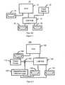
- FIG. 1depicts a conventional computer system 10 that has USB connectors.
- the conventional computer system 10could be a number of computer systems, including for example, a notebook computer or desk top computer.
- the conventional computer system 10includes a host 12 , a first USB connector 14 , a USB hub 16 , USB connectors 18 and 20 and a power supply 22 .
- the host 12includes the integrated circuits and, therefore, the processor (not explicitly shown) that operate the operating system (not explicitly shown) for the computer system 10 .
- the host 12might include four INTELTM integrated circuits.
- the host 12might include INTELTM processors which run a MICROSOFTTM operating system.
- the conventional computer system 10also includes the USB connector 14 .
- the conventional computer system 10could include another USB connector (not explicitly shown) and operate as desired. Due to the popularity of USB connectivity, the conventional computer system 10 is desired to have a larger number of USB connectors. Consequently, the USB hub 16 that connects the host 12 to USB connectors 18 and 20 is provided. Thus, the USB hub 16 allows additional USB connectors 18 and 20 to be integrated into the computer system 10 . In order to operate, the USB hub may connected to and be supplied with power from the power supply 22 .
- the conventional computer system 10includes the components 12 , 14 , 16 , 18 , 20 and 22 integrated into a housing.
- the conventional computer system 10functions, one of ordinary skill in the art will readily realize the conventional computer system 10 may use a higher amount of power than desired.
- a USB device attached to a USB connectorprecludes the processor from entering a lowest power state, known as a C3 state.
- the operating system for the host 12detects the presence of a USB device then the processor cannot enter its lowest power state.
- the operating system in the host 12considers the USB hub 16 , which is integrated into the conventional computer system 10 , to be a USB device.
- the conventional computer system 10may, therefore, consume more power than is desirable.
- the conventional computer system 10is a computer system, such as a notebook, that has a mobile mode.
- the power supply 22includes a battery for supplying power to the conventional computer system 10 when in mobile mode.
- the batteryWhen in the mobile mode, it is desirable to allow the host 12 to enter a lowest power state in order to conserve battery power, for example when the host 12 is not actively being used. Because the processors in the host 12 cannot enter the lowest power state, the battery will discharge more rapidly. The battery may lose its charge, preventing the user from utilizing the conventional computer system 10 when desired.
- the present inventionprovides a method and system for managing power in a computer system.
- the computer systemincludes a host.
- the method and systemcomprise providing a Universal Serial Bus (USB) hub, at least one USB connector and attach/removal detection logic.
- the at least one USB connectoris coupled with the USB hub.
- the attach/removal detection logicis coupled with the USB hub.
- the attach/removal detection logicdetermines whether a USB device is connected to the at least one USB connector, logically decouples the USB hub from the host if the USB device is not connected to the at least one USB connector and logically couples the USB hub to the host if the USB device is connected to the at least one USB connector.
- the present inventionallows power to be managed in the computer system by allowing processors in the host to go to a lower power state.
- FIG. 1is a block diagram of a conventional computer system having a USB hub.
- FIG. 2is a block diagram of one embodiment of a computer system in accordance with the present invention having a USB hub.
- FIG. 3is a block diagram of a second embodiment of a computer system in accordance with the present invention having a USB hub.
- FIG. 4is a more detailed block diagram of the second embodiment of a computer system in accordance with the present invention having a USB hub.
- the present inventionrelates to an improvement in computer systems.
- the following descriptionis presented to enable one of ordinary skill in the art to make and use the invention and is provided in the context of a patent application and its requirements.
- Various modifications to the preferred embodimentwill be readily apparent to those skilled in the art and the generic principles herein may be applied to other embodiments.
- the present inventionis not intended to be limited to the embodiment shown, but is to be accorded the widest scope consistent with the principles and features described herein.
- a conventional computer systemmay include a host, a USB hub and multiple USB connectors integrated into a single unit.
- the hosttypically includes one or more integrated circuits, including at least one processor, that run an operating system (“OS”) for the conventional computer system.
- OSoperating system
- the USB hubis coupled with the host. Coupled to the USB hub are multiple USB connectors that allow USB devices to be coupled to the conventional computer system.
- the conventional computer systemallows a larger number of USB devices to be used with the conventional computer system, one of ordinary skill in the art will realize that the conventional computer system may not be able to adequately manage power.
- the conventional computer systemas required by USB specifications, considers the USB hub to be a USB device connected to the conventional computer system. Consequently, processors in the host of the conventional computer system cannot enter certain power states. As a result, the conventional computer system may consume more power than is desired.
- the present inventionprovides a method and system for managing power in a computer system.
- the computer systemincludes a host.
- the method and systemcomprise providing a Universal Serial Bus (USB) hub, at least one USB connector and attach/removal detection logic.
- the at least one USB connectoris coupled with the USB hub.
- the attach/removal detection logicis coupled with the USB hub.
- the attach/removal detection logicdetermines whether a USB device is connected to the at least one USB connector, logically decouples the USB hub from the host if the USB device is not connected to the at least one USB connector and logically couples the USB hub to the host if the USB device is connected to the at least one USB connector.
- FIG. 2is a high-level block diagram that depicts one embodiment of a computer system 100 in accordance with the present invention.
- the computer system 100includes a host 102 , a first USB connector 104 , a USB hub 106 , USB connectors 108 and 110 connected to the USB hub 106 , a power supply 112 coupled with the USB hub 106 , attach/removal detection logic 120 and connector 122 .
- the host 102 , the first USB connector 104 , the USB hub 106 , the USB connectors 108 and 110 and the power supply 112are preferably substantially the same as the host 12 , the first USB connector 14 , the USB hub 16 , the USB connectors 18 and 20 and the power supply 22 of the conventional system 10 depicted in FIG. 1 .
- the attach/removal detection logic 120is coupled with the USB connectors 108 and 110 and with the power supply 112 and USB hub 108 through the connector 122 .
- the attach/removal detection logic 120detects whether a USB device (not shown) is plugged into either of the USB connectors 108 and 110 .
- the attach/removal detection logic 120functions to logically decouple the USB hub 106 from the host 102 if a USB device is not connected any of the USB connectors 108 and 110 .
- the attach/removal detection logic 120also logically couples the USB hub 106 to the host 102 if a USB device is coupled to any of the USB connectors 108 and 110 .
- the attach/removal detection logic 120does this by controlling the connector 122 .
- the attach/removal detection logic 120controls the connector 122 so that the connector 122 couples the USB hub 106 to the power supply 112 when a USB device is coupled to either of the USB connectors 108 and 110 and so that the connector 122 does not couple the USB hub 106 to the power supply 112 when the USB device is not coupled to either of the USB connectors 108 and 110 .
- poweris only supplied to the USB hub 106 when one or more of the USB connectors 108 and 110 provided through the USB hub 106 is in use.
- the computer system 100can better manage power.
- the operating system of the host 102can only recognize the USB hub 106 if power is supplied to the USB hub 106 . Because the attach/removal detection logic 120 and the connector 122 ensure that the power supply 112 is connected to the USB hub 106 only when one or more of the USB connectors 108 and 110 , the operating system can only recognize the USB hub 106 when a USB device is connected to one or more of the USB connectors 108 and 110 . In other words, the USB hub 106 is logically decoupled from the host 102 when a USB device is not coupled to either of the USB connectors 108 and 110 .
- the USB hub 106is logically coupled to the host when a USB device is connected to one or more of the USB connectors 108 and 110 . This is true even though the USB hub 106 remains physically connected to the host 102 at all times.
- the operating system for the host 102only considers the USB hub 106 to be a USB device coupled to the host 102 when one or more of the USB connectors 108 and 110 are in use. When these connectors are not in use, therefore, the processors for the host 102 can enter a lowest power state. Thus, power will not be utilized unnecessarily due to the presence of the USB hub 106 . Therefore, power for the computer system 100 can be better managed.
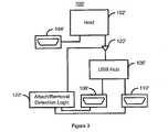
- FIG. 3is a block diagram of a second embodiment of a computer system 100 ′ in accordance with the present invention having a USB hub.
- the computer system 100 ′includes analogous components to those in the computer system 100 . Consequently, these items are labeled similarly. However, for clarity, certain components are not depicted.
- the computer system 100 ′includes a host 102 ′, a USB connector 104 ′ connected to the host 102 ′, a USB hub 106 ′, and USB connectors 108 ′ and 110 ′ coupled to the USB hub 106 ′.
- the computer system 100 ′also includes attach/removal detection logic 120 ′ and connector 122 ′.
- the connector 122 ′is coupled between the host 102 ′ and the USB hub 106 ′.
- the attach/removal detection logic 120 ′still logically decouples the USB hub 106 ′ from the host 102 ′ if a USB device is not connected any of the USB connectors 108 ′ and 110 ′.
- the attach/removal detection logic 120 ′also logically couples the USB hub 106 ′ to the host 102 ′ if a USB device is coupled to any of the USB connectors 108 ′ and 110 ′.
- the attach/removal detection logic 120 ′performs these functions by controlling the connector 122 ′.
- the attach/removal detection logic 120 ′controls the connector 122 ′ so that the connector 122 ′ couples the USB hub 106 ′ to the host 102 ′ when a USB device is coupled to either of the USB connectors 108 ′ and 110 ′.
- the attach/removal detection logic 120 ′controls the 122 ′ so that the connector 122 ′ does not couple the USB hub 106 ′ to the host 102 ′ when the USB device is not coupled to either of the USB connectors 108 ′ and 110 ′.
- the computer system 100 ′can better manage power.
- the operating system of the host 102 ′can only recognize the USB hub 106 ′ if the host 102 ′ is coupled to the USB hub 106 ′. Because the attach/removal detection logic 120 ′ and the connector 122 ′ couples the USB hub 106 ′ to the host 102 ′ only when one or more of the USB connectors 108 ′ and 110 ′, the operating system can only recognize the USB hub 106 when a USB device is connected to one or more of the USB connectors 108 ′ and 110 ′.
- the USB hub 106 ′is logically decoupled from the host when a USB device is not coupled to either of the USB connectors 108 ′ and 110 ′.
- the USB hub 106 ′is logically coupled to the host when a USB device is connected to one or more of the USB connectors 108 ′ and 110 ′.
- the operating system for the host 102 ′only considers the USB hub 106 ′ to be a USB device coupled to the host 102 ′ when one or more of the USB connectors 108 ′ and 110 ′ are in use. When these connectors are not in use, therefore, the processors for the host 102 ′ can enter a lowest power state. Thus, power will not be utilized unnecessarily due to the presence of the USB hub 106 ′. Therefore, power for the computer system 100 ′ can be better managed.
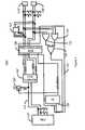
- FIG. 4is a more detailed block diagram of the second embodiment of a computer system 100 ′′ in accordance with the present invention having a USB hub 106 ′′.
- the computer system 100 ′′includes analogous components to those in the computer system 100 . Consequently, these items are labeled similarly. However, for clarity, certain components are not depicted.
- the computer system 100 ′′includes processors 102 ′′ which would reside in a host for the computer system 100 ′′, a USB hub 106 ′′, USB connectors 108 ′′ and 110 ′′.
- the computer system 100 ′′also includes attach/removal detection logic 120 ′′ and connector 122 ′′.
- the computer system 100 ′′includes a transient suppressor 124 .
- the transient suppressor 124is used to prevent damage due to electrostatic discharge when a USB device (not shown) is hot attached to one of the connectors 106 ′′ and 108 ′′.
- the attach removal detection logicincludes integrated circuits 126 and 128 and logic gates 130 , 132 and 134 .
- the connector 122 ′′is a FET.
- the connector 122 ′′is not a connector in the traditional sense of the word in that the connector 122 ′′ does not physically decouple the USB hub 106 ′′ from the processors 102 ′′.
- the connector 122 ′′is a connector in the sense that it allows the USB hub 106 ′′ to be logically coupled or decoupled from the processor 102 ′′.
- the attach/removal detection logic 120 ′′When a USB device is connected to a USB connector 108 ′′ or 110 ′′, the attach/removal detection logic 120 ′′ provides a signal (H 8 USBON) that is on. When this signal is on, the FET 122 ′′ is turned on. Thus, the line 121 between the processors 102 ′′ and the USB hub 106 ′′ is driven high when a USB device is connected to one of the connectors 108 ′′ or 110 ′′. As a result, the USB hub 106 ′′ is connected to the processors 102 ′′ only when the USB connector 108 ′′ or 110 ′′ is in use. Thus, the processors 102 ′′ only recognize the USB hub 106 ′′ as a USB device when the USB connector 108 ′′ or 110 ′′ is being used.
- the processors 102 ′′behave as though the USB hub 106 ′′ is not present in the computer system 100 ′′. Therefore, the processors 102 ′′ can enter a lowest power state when the USB connectors 108 ′′ and 110 ′′ are not in use. Thus, power can be better managed in the computer system 100 ′′.
Landscapes
- Engineering & Computer Science (AREA)
- Theoretical Computer Science (AREA)
- General Engineering & Computer Science (AREA)
- Physics & Mathematics (AREA)
- General Physics & Mathematics (AREA)
- Computer Hardware Design (AREA)
- Power Sources (AREA)
Abstract
Description
Claims (10)
Priority Applications (11)
| Application Number | Priority Date | Filing Date | Title |
|---|---|---|---|
| US09/802,659US6928562B2 (en) | 2001-03-09 | 2001-03-09 | Method and system for managing power in a system having an internal USB HUB |
| IL14337801AIL143378A0 (en) | 2001-03-09 | 2001-05-24 | Method and system for managing power in a system having an internal usb hub |
| KR10-2003-7009350AKR100523417B1 (en) | 2001-01-18 | 2001-12-11 | Power managing in a system having internal usb hub |
| EP01273738AEP1360571A4 (en) | 2001-01-18 | 2001-12-11 | Power managing in a system having internal usb hub |
| JP2002564719AJP3810368B2 (en) | 2001-01-18 | 2001-12-11 | Method and system for managing power in a system having an internal USB hub |
| CNB018230091ACN1256643C (en) | 2001-01-18 | 2001-12-11 | Power management method and system for a system with a built-in USB hub |
| HU0302769AHUP0302769A3 (en) | 2001-01-18 | 2001-12-11 | Method and system for managing power in a computer system |
| PCT/US2001/047259WO2002065264A1 (en) | 2001-01-18 | 2001-12-11 | Power managing in a system having internal usb hub |
| PL362602APL205182B1 (en) | 2001-01-18 | 2001-12-11 | Power managing in a system having internal usb hub |
| CZ20031965ACZ20031965A3 (en) | 2001-01-18 | 2001-12-11 | Method and system for controlling feeding in a system fitted with internal USB hub |
| TW091100463ATWI222553B (en) | 2001-01-18 | 2002-01-15 | Method and system for managing power in a system having an internal USB hub |
Applications Claiming Priority (1)
| Application Number | Priority Date | Filing Date | Title |
|---|---|---|---|
| US09/802,659US6928562B2 (en) | 2001-03-09 | 2001-03-09 | Method and system for managing power in a system having an internal USB HUB |
Publications (2)
| Publication Number | Publication Date |
|---|---|
| US20020138776A1 US20020138776A1 (en) | 2002-09-26 |
| US6928562B2true US6928562B2 (en) | 2005-08-09 |
Family
ID=25184347
Family Applications (1)
| Application Number | Title | Priority Date | Filing Date |
|---|---|---|---|
| US09/802,659Expired - LifetimeUS6928562B2 (en) | 2001-01-18 | 2001-03-09 | Method and system for managing power in a system having an internal USB HUB |
Country Status (2)
| Country | Link |
|---|---|
| US (1) | US6928562B2 (en) |
| IL (1) | IL143378A0 (en) |
Cited By (34)
| Publication number | Priority date | Publication date | Assignee | Title |
|---|---|---|---|---|
| US20030221135A1 (en)* | 2002-03-20 | 2003-11-27 | Hironori Motoe | Power supply control device |
| US20040017112A1 (en)* | 2002-07-23 | 2004-01-29 | Samsung Electronics Co., Ltd. | Power supply controlling device of an electronic equipment |
| US20040033734A1 (en)* | 2002-06-19 | 2004-02-19 | Hewlett-Packard Development Company, L.P. | Internal USB circuit connection |
| US20050156037A1 (en)* | 2004-01-20 | 2005-07-21 | Henry Wurzburg | Automatic drive icon assignment by media type in single slot USB card readers |
| US20050160196A1 (en)* | 2004-01-20 | 2005-07-21 | Standard Microsystems Corporation | Power managed USB for computing applications using a controller |
| US20050156038A1 (en)* | 2004-01-20 | 2005-07-21 | Henry Wurzburg | Peripheral device feature allowing processors to enter a low power state |
| US20050240708A1 (en)* | 2004-04-21 | 2005-10-27 | Shaver Charles N | Systems and methods for providing internal universal serial bus ports |
| US20050264552A1 (en)* | 1999-09-22 | 2005-12-01 | Sony Corporation | Information processing apparatus, display control method, and recording medium |
| US20060047880A1 (en)* | 2004-08-27 | 2006-03-02 | Imation Corp. | Memory device with HUB capability |
| US20060095641A1 (en)* | 2004-11-01 | 2006-05-04 | Amol Pandit | System and method for dynamic USB power source |
| US20060173581A1 (en)* | 2005-01-31 | 2006-08-03 | Shimon Elkayam | Preventing excess port voltage during disconnect |
| US20070013689A1 (en)* | 2005-07-12 | 2007-01-18 | Choi Byeong-Bae | Display apparatus with usb hub |
| US20080235524A1 (en)* | 2007-03-16 | 2008-09-25 | Sharma Yugal K | System for peripheral re-enumeration |
| US7433990B2 (en) | 2006-01-24 | 2008-10-07 | Standard Microsystems Corporation | Transferring system information via universal serial bus (USB) |
| US20090037622A1 (en)* | 2007-08-02 | 2009-02-05 | Broadcom Corporation | Method and system for changing operation modes of an interface device |
| US20090077400A1 (en)* | 2007-09-14 | 2009-03-19 | Eiji Enami | Power control system |
| US20100026362A1 (en)* | 2008-07-29 | 2010-02-04 | Qualcomm Incorporated | High signal level compliant input/output circuits |
| US20100030924A1 (en)* | 2008-07-29 | 2010-02-04 | Qualcomm Incorporated | High signal level compliant input/output circuits |
| US20100026363A1 (en)* | 2008-07-29 | 2010-02-04 | Qualcomm Incorporated | High signal level compliant input/output circuits |
| US20100026364A1 (en)* | 2008-07-29 | 2010-02-04 | Qualcomm Incorporated | High signal level compliant input/output circuits |
| US20100058085A1 (en)* | 2008-09-03 | 2010-03-04 | Realtek Semiconductor Corp. | Power-Saving Device and Method |
| US20100199112A1 (en)* | 2009-01-30 | 2010-08-05 | Kabushiki Kaisha Toshiba | Information processing apparatus and power supply control method |
| US7882297B2 (en) | 2009-02-20 | 2011-02-01 | Standard Microsystems Corporation | Serial bus hub with low power devices |
| US8138814B2 (en) | 2008-07-29 | 2012-03-20 | Qualcomm Incorporated | High signal level compliant input/output circuits |
| US8185759B1 (en) | 2008-11-06 | 2012-05-22 | Smsc Holdings S.A.R.L. | Methods and systems for interfacing bus powered devices with host devices providing limited power levels |
| US20120151231A1 (en)* | 2010-12-09 | 2012-06-14 | Atsushi Hatta | Power supply switching device, a power supply switching device control method and a power supply control program |
| US8631284B2 (en) | 2010-04-30 | 2014-01-14 | Western Digital Technologies, Inc. | Method for providing asynchronous event notification in systems |
| US8762682B1 (en) | 2010-07-02 | 2014-06-24 | Western Digital Technologies, Inc. | Data storage apparatus providing host full duplex operations using half duplex storage devices |
| US20140280960A1 (en)* | 2013-03-15 | 2014-09-18 | Apple, Inc. | Methods and apparatus for dynamically allocating devices between multiple controllers |
| US20150067374A1 (en)* | 2013-09-04 | 2015-03-05 | Samsung Electronics Co., Ltd. | Electronic device, control method of electronic device, and image forming apparatus |
| US20150372520A1 (en)* | 2008-04-28 | 2015-12-24 | Dell Products L.P. | Device charging system |
| US9477437B2 (en) | 2012-10-02 | 2016-10-25 | Apple Inc. | Sharing a graphics-processing-unit display port |
| US9747237B2 (en) | 2013-06-11 | 2017-08-29 | Apple Inc. | Methods and apparatus for reliable detection and enumeration of devices |
| US20220327079A1 (en)* | 2021-04-09 | 2022-10-13 | Dell Products L.P. | Discovery and safe enablement of high-speed management interface via pcie card electro-mechanical connector |
Families Citing this family (8)
| Publication number | Priority date | Publication date | Assignee | Title |
|---|---|---|---|---|
| US8473664B2 (en)* | 2006-12-11 | 2013-06-25 | Intel Corporation | Safe removal of external device from computing device |
| KR101282257B1 (en) | 2008-04-24 | 2013-07-10 | 삼성전자주식회사 | Computer system and control method thereof |
| US8510583B2 (en)* | 2010-07-01 | 2013-08-13 | Intel Corporation | Asynchronous sleep mode for host controller |
| CN102081581B (en)* | 2010-10-01 | 2013-10-30 | 威盛电子股份有限公司 | Power management system and method |
| KR101946028B1 (en)* | 2012-08-31 | 2019-02-08 | 삼성전자주식회사 | IO port and electronic apparatus having the same |
| FR2998070A1 (en)* | 2012-11-14 | 2014-05-16 | Thomson Licensing | DETECTION OF USB DEVICE ON A NON-POWERED BUS |
| CN105988545A (en)* | 2015-02-09 | 2016-10-05 | 鸿富锦精密工业(武汉)有限公司 | Electronic device and power supply interface |
| CN105138483B (en)* | 2015-07-30 | 2017-12-19 | 浪潮软件集团有限公司 | USB interface expansion device and communication method thereof |
Citations (8)
| Publication number | Priority date | Publication date | Assignee | Title |
|---|---|---|---|---|
| US5167024A (en) | 1989-09-08 | 1992-11-24 | Apple Computer, Inc. | Power management for a laptop computer with slow and sleep modes |
| US5675813A (en) | 1995-10-26 | 1997-10-07 | Microsoft Corporation | System and method for power control in a universal serial bus |
| US5799196A (en) | 1996-07-02 | 1998-08-25 | Gateway 2000, Inc. | Method and apparatus of providing power management using a self-powered universal serial bus (USB) device |
| US6216188B1 (en)* | 1998-01-12 | 2001-04-10 | Alps Electric Co., Ltd. | Computer system having computer provided with universal-serial-bus and device conforming to universal-serial-bus standard |
| US6279060B1 (en)* | 1998-12-04 | 2001-08-21 | In-System Design, Inc. | Universal serial bus peripheral bridge simulates a device disconnect condition to a host when the device is in a not-ready condition to avoid wasting bus resources |
| US6415342B1 (en)* | 1999-07-27 | 2002-07-02 | Hewlett-Packard Company | Universal serial bus controlled connect and disconnect |
| US6493770B1 (en)* | 1997-07-02 | 2002-12-10 | Cypress Semiconductor Corp. | System for reconfiguring a peripheral device by downloading information from a host and electronically simulating a physical disconnection and reconnection to reconfigure the device |
| US6671814B1 (en)* | 1998-09-29 | 2003-12-30 | Nec Corporation | USB device and USB connecting system |
- 2001
- 2001-03-09USUS09/802,659patent/US6928562B2/ennot_activeExpired - Lifetime
- 2001-05-24ILIL14337801Apatent/IL143378A0/enunknown
Patent Citations (8)
| Publication number | Priority date | Publication date | Assignee | Title |
|---|---|---|---|---|
| US5167024A (en) | 1989-09-08 | 1992-11-24 | Apple Computer, Inc. | Power management for a laptop computer with slow and sleep modes |
| US5675813A (en) | 1995-10-26 | 1997-10-07 | Microsoft Corporation | System and method for power control in a universal serial bus |
| US5799196A (en) | 1996-07-02 | 1998-08-25 | Gateway 2000, Inc. | Method and apparatus of providing power management using a self-powered universal serial bus (USB) device |
| US6493770B1 (en)* | 1997-07-02 | 2002-12-10 | Cypress Semiconductor Corp. | System for reconfiguring a peripheral device by downloading information from a host and electronically simulating a physical disconnection and reconnection to reconfigure the device |
| US6216188B1 (en)* | 1998-01-12 | 2001-04-10 | Alps Electric Co., Ltd. | Computer system having computer provided with universal-serial-bus and device conforming to universal-serial-bus standard |
| US6671814B1 (en)* | 1998-09-29 | 2003-12-30 | Nec Corporation | USB device and USB connecting system |
| US6279060B1 (en)* | 1998-12-04 | 2001-08-21 | In-System Design, Inc. | Universal serial bus peripheral bridge simulates a device disconnect condition to a host when the device is in a not-ready condition to avoid wasting bus resources |
| US6415342B1 (en)* | 1999-07-27 | 2002-07-02 | Hewlett-Packard Company | Universal serial bus controlled connect and disconnect |
Cited By (53)
| Publication number | Priority date | Publication date | Assignee | Title |
|---|---|---|---|---|
| US20050264552A1 (en)* | 1999-09-22 | 2005-12-01 | Sony Corporation | Information processing apparatus, display control method, and recording medium |
| US7386742B2 (en)* | 1999-09-22 | 2008-06-10 | Sony Corporation | Method and apparatus for controlling power to a first and second circuit based on an operational mode and connecting state of an information processing apparatus |
| US20030221135A1 (en)* | 2002-03-20 | 2003-11-27 | Hironori Motoe | Power supply control device |
| US20040033734A1 (en)* | 2002-06-19 | 2004-02-19 | Hewlett-Packard Development Company, L.P. | Internal USB circuit connection |
| US7124215B2 (en)* | 2002-06-19 | 2006-10-17 | Hewlett-Packard Development Company, L.P. | Internal USB circuit connection |
| US20040017112A1 (en)* | 2002-07-23 | 2004-01-29 | Samsung Electronics Co., Ltd. | Power supply controlling device of an electronic equipment |
| US7002814B2 (en)* | 2002-07-23 | 2006-02-21 | Samsung Electronics Co., Ltd. | Power supply controlling device of an electronic equipment |
| US7159766B2 (en)* | 2004-01-20 | 2007-01-09 | Standard Microsystems Corporation | Peripheral device feature allowing processors to enter a low power state |
| US8572420B2 (en) | 2004-01-20 | 2013-10-29 | Standard Microsystems Corporation | Power managed USB for computing applications using a controller |
| US20050156037A1 (en)* | 2004-01-20 | 2005-07-21 | Henry Wurzburg | Automatic drive icon assignment by media type in single slot USB card readers |
| US20050156038A1 (en)* | 2004-01-20 | 2005-07-21 | Henry Wurzburg | Peripheral device feature allowing processors to enter a low power state |
| US7131595B2 (en) | 2004-01-20 | 2006-11-07 | Standard Microsystems Corporation | Automatic drive icon assignment by media type in single slot USB card readers |
| US20050160196A1 (en)* | 2004-01-20 | 2005-07-21 | Standard Microsystems Corporation | Power managed USB for computing applications using a controller |
| US7325733B2 (en) | 2004-01-20 | 2008-02-05 | Standard Microsystems Corporation | Electrically disconnecting a peripheral device |
| US20070023499A1 (en)* | 2004-01-20 | 2007-02-01 | Henry Wurzburg | Electrically Disconnecting a Peripheral Device |
| US20050240708A1 (en)* | 2004-04-21 | 2005-10-27 | Shaver Charles N | Systems and methods for providing internal universal serial bus ports |
| US20060047880A1 (en)* | 2004-08-27 | 2006-03-02 | Imation Corp. | Memory device with HUB capability |
| US7310697B2 (en)* | 2004-11-01 | 2007-12-18 | Hewlett-Packard Development Company, L.P. | System and method for dynamic USB power source |
| US20060095641A1 (en)* | 2004-11-01 | 2006-05-04 | Amol Pandit | System and method for dynamic USB power source |
| US7281141B2 (en)* | 2005-01-31 | 2007-10-09 | Powersdsine, Ltd.-Microsemi Corporation | Bypass discharge path for a power sourcing equipment |
| US20060173581A1 (en)* | 2005-01-31 | 2006-08-03 | Shimon Elkayam | Preventing excess port voltage during disconnect |
| US20070013689A1 (en)* | 2005-07-12 | 2007-01-18 | Choi Byeong-Bae | Display apparatus with usb hub |
| US7433990B2 (en) | 2006-01-24 | 2008-10-07 | Standard Microsystems Corporation | Transferring system information via universal serial bus (USB) |
| US20080235524A1 (en)* | 2007-03-16 | 2008-09-25 | Sharma Yugal K | System for peripheral re-enumeration |
| US20090037622A1 (en)* | 2007-08-02 | 2009-02-05 | Broadcom Corporation | Method and system for changing operation modes of an interface device |
| US8046613B2 (en)* | 2007-09-14 | 2011-10-25 | Ricoh Company, Limited | Power control system |
| US20090077400A1 (en)* | 2007-09-14 | 2009-03-19 | Eiji Enami | Power control system |
| US12142961B2 (en) | 2008-04-28 | 2024-11-12 | Dell Products L.P. | Device charging system |
| US11146095B2 (en)* | 2008-04-28 | 2021-10-12 | Dell Products L.P. | Device charging system |
| US20150372520A1 (en)* | 2008-04-28 | 2015-12-24 | Dell Products L.P. | Device charging system |
| US20100030924A1 (en)* | 2008-07-29 | 2010-02-04 | Qualcomm Incorporated | High signal level compliant input/output circuits |
| US20100026364A1 (en)* | 2008-07-29 | 2010-02-04 | Qualcomm Incorporated | High signal level compliant input/output circuits |
| US7804334B2 (en) | 2008-07-29 | 2010-09-28 | Qualcomm Incorporated | High signal level compliant input/output circuits |
| US8106699B2 (en) | 2008-07-29 | 2012-01-31 | Qualcomm Incorporated | High signal level compliant input/output circuits |
| US8138814B2 (en) | 2008-07-29 | 2012-03-20 | Qualcomm Incorporated | High signal level compliant input/output circuits |
| US20100026362A1 (en)* | 2008-07-29 | 2010-02-04 | Qualcomm Incorporated | High signal level compliant input/output circuits |
| US8593203B2 (en) | 2008-07-29 | 2013-11-26 | Qualcomm Incorporated | High signal level compliant input/output circuits |
| US7772887B2 (en)* | 2008-07-29 | 2010-08-10 | Qualcomm Incorporated | High signal level compliant input/output circuits |
| US20100026363A1 (en)* | 2008-07-29 | 2010-02-04 | Qualcomm Incorporated | High signal level compliant input/output circuits |
| US20100058085A1 (en)* | 2008-09-03 | 2010-03-04 | Realtek Semiconductor Corp. | Power-Saving Device and Method |
| US8185759B1 (en) | 2008-11-06 | 2012-05-22 | Smsc Holdings S.A.R.L. | Methods and systems for interfacing bus powered devices with host devices providing limited power levels |
| US20100199112A1 (en)* | 2009-01-30 | 2010-08-05 | Kabushiki Kaisha Toshiba | Information processing apparatus and power supply control method |
| US7882297B2 (en) | 2009-02-20 | 2011-02-01 | Standard Microsystems Corporation | Serial bus hub with low power devices |
| US8631284B2 (en) | 2010-04-30 | 2014-01-14 | Western Digital Technologies, Inc. | Method for providing asynchronous event notification in systems |
| US8762682B1 (en) | 2010-07-02 | 2014-06-24 | Western Digital Technologies, Inc. | Data storage apparatus providing host full duplex operations using half duplex storage devices |
| US20120151231A1 (en)* | 2010-12-09 | 2012-06-14 | Atsushi Hatta | Power supply switching device, a power supply switching device control method and a power supply control program |
| US9477437B2 (en) | 2012-10-02 | 2016-10-25 | Apple Inc. | Sharing a graphics-processing-unit display port |
| US20140280960A1 (en)* | 2013-03-15 | 2014-09-18 | Apple, Inc. | Methods and apparatus for dynamically allocating devices between multiple controllers |
| US9747237B2 (en) | 2013-06-11 | 2017-08-29 | Apple Inc. | Methods and apparatus for reliable detection and enumeration of devices |
| US20150067374A1 (en)* | 2013-09-04 | 2015-03-05 | Samsung Electronics Co., Ltd. | Electronic device, control method of electronic device, and image forming apparatus |
| US9766688B2 (en)* | 2013-09-04 | 2017-09-19 | Samsung Electronics Co., Ltd. | Electronic device, control method of electronic device, and image forming apparatus |
| US20220327079A1 (en)* | 2021-04-09 | 2022-10-13 | Dell Products L.P. | Discovery and safe enablement of high-speed management interface via pcie card electro-mechanical connector |
| US11748288B2 (en)* | 2021-04-09 | 2023-09-05 | Dell Products L.P. | Discovery and safe enablement of high-speed management interface via PCIe card electro-mechanical connector |
Also Published As
| Publication number | Publication date |
|---|---|
| IL143378A0 (en) | 2002-04-21 |
| US20020138776A1 (en) | 2002-09-26 |
Similar Documents
| Publication | Publication Date | Title |
|---|---|---|
| US6928562B2 (en) | Method and system for managing power in a system having an internal USB HUB | |
| WO2002065264A1 (en) | Power managing in a system having internal usb hub | |
| JP6531208B2 (en) | Low Power Implementation of Type-C Connector Subsystem | |
| US7502947B2 (en) | System and method of controlling a graphics controller | |
| US8726051B2 (en) | Computer system for supplying electric power to external apparatus and control method thereof | |
| US20030056051A1 (en) | System and method for connecting a universal serial bus device to a host computer system | |
| JPH10124206A (en) | Method and device for supplying portable computer having modular bay realizing hot plug | |
| US6275240B1 (en) | Method and apparatus for maintaining load balance on a graphics bus when an upgrade device is installed | |
| US7028126B1 (en) | Universal serial bus for mobile devices having expansion modules | |
| US6990546B2 (en) | Hot docking drive wedge and port replicator | |
| US20040033734A1 (en) | Internal USB circuit connection | |
| US6578152B1 (en) | Dual power switching network system for isolating between different power supplies and applying appropriate power supply to a connected peripheral device | |
| JP4387493B2 (en) | Computer system and method for controlling the same | |
| US6742027B1 (en) | Data processing system and method for permitting a server to remotely disable a client computer system's input device | |
| US6243782B1 (en) | Method and apparatus for disabling a graphics device when an upgrade device is installed | |
| US7085939B2 (en) | Method and apparatus for supplying power to a bus-controlled component of a computer | |
| US7155624B2 (en) | Powered newcard connector | |
| US11899600B2 (en) | Serial connector adapter system | |
| CN101526841A (en) | Computer system and power saving method | |
| US7003608B2 (en) | Method and system for automatic configuration of IDE bus devices | |
| US6262605B1 (en) | Automated line driver control circuit for power managed system |
Legal Events
| Date | Code | Title | Description |
|---|---|---|---|
| AS | Assignment | Owner name:INTERNATIONAL BUSINESS MACHINES CORP., NEW YORK Free format text:ASSIGNMENT OF ASSIGNORS INTEREST;ASSIGNORS:COHEN, MARK EVAN;LOEBACH, JAMES CHRISTOPHER;MUTI, JR., CARL JOSEPH;AND OTHERS;REEL/FRAME:011688/0985;SIGNING DATES FROM 20010301 TO 20010309 | |
| STCF | Information on status: patent grant | Free format text:PATENTED CASE | |
| AS | Assignment | Owner name:LENOVO (SINGAPORE) PTE LTD., SINGAPORE Free format text:ASSIGNMENT OF ASSIGNORS INTEREST;ASSIGNOR:INTERNATIONAL BUSINESS MACHINES CORPORATION;REEL/FRAME:016891/0507 Effective date:20050520 Owner name:LENOVO (SINGAPORE) PTE LTD.,SINGAPORE Free format text:ASSIGNMENT OF ASSIGNORS INTEREST;ASSIGNOR:INTERNATIONAL BUSINESS MACHINES CORPORATION;REEL/FRAME:016891/0507 Effective date:20050520 | |
| FPAY | Fee payment | Year of fee payment:4 | |
| FPAY | Fee payment | Year of fee payment:8 | |
| AS | Assignment | Owner name:LENOVO PC INTERNATIONAL, HONG KONG Free format text:NUNC PRO TUNC ASSIGNMENT;ASSIGNOR:LENOVO (SINGAPORE) PTE LTD.;REEL/FRAME:037160/0001 Effective date:20130401 | |
| FPAY | Fee payment | Year of fee payment:12 |