US6928471B2 - Method and apparatus for measurement, analysis, and optimization of content delivery - Google Patents
Method and apparatus for measurement, analysis, and optimization of content deliveryDownload PDFInfo
- Publication number
- US6928471B2 US6928471B2US09/850,877US85087701AUS6928471B2US 6928471 B2US6928471 B2US 6928471B2US 85087701 AUS85087701 AUS 85087701AUS 6928471 B2US6928471 B2US 6928471B2
- Authority
- US
- United States
- Prior art keywords
- data
- analyzer
- application
- server
- layer
- Prior art date
- Legal status (The legal status is an assumption and is not a legal conclusion. Google has not performed a legal analysis and makes no representation as to the accuracy of the status listed.)
- Expired - Lifetime, expires
Links
Images


Classifications
- H—ELECTRICITY
- H04—ELECTRIC COMMUNICATION TECHNIQUE
- H04L—TRANSMISSION OF DIGITAL INFORMATION, e.g. TELEGRAPHIC COMMUNICATION
- H04L43/00—Arrangements for monitoring or testing data switching networks
- H04L43/02—Capturing of monitoring data
- H04L43/028—Capturing of monitoring data by filtering
- H—ELECTRICITY
- H04—ELECTRIC COMMUNICATION TECHNIQUE
- H04L—TRANSMISSION OF DIGITAL INFORMATION, e.g. TELEGRAPHIC COMMUNICATION
- H04L41/00—Arrangements for maintenance, administration or management of data switching networks, e.g. of packet switching networks
- H04L41/14—Network analysis or design
- H04L41/142—Network analysis or design using statistical or mathematical methods
- H—ELECTRICITY
- H04—ELECTRIC COMMUNICATION TECHNIQUE
- H04L—TRANSMISSION OF DIGITAL INFORMATION, e.g. TELEGRAPHIC COMMUNICATION
- H04L67/00—Network arrangements or protocols for supporting network services or applications
- H04L67/50—Network services
- H04L67/535—Tracking the activity of the user
- H—ELECTRICITY
- H04—ELECTRIC COMMUNICATION TECHNIQUE
- H04L—TRANSMISSION OF DIGITAL INFORMATION, e.g. TELEGRAPHIC COMMUNICATION
- H04L67/00—Network arrangements or protocols for supporting network services or applications
- H04L67/50—Network services
- H04L67/60—Scheduling or organising the servicing of application requests, e.g. requests for application data transmissions using the analysis and optimisation of the required network resources
- H04L67/63—Routing a service request depending on the request content or context
- H—ELECTRICITY
- H04—ELECTRIC COMMUNICATION TECHNIQUE
- H04L—TRANSMISSION OF DIGITAL INFORMATION, e.g. TELEGRAPHIC COMMUNICATION
- H04L69/00—Network arrangements, protocols or services independent of the application payload and not provided for in the other groups of this subclass
- H04L69/16—Implementation or adaptation of Internet protocol [IP], of transmission control protocol [TCP] or of user datagram protocol [UDP]
- H04L69/161—Implementation details of TCP/IP or UDP/IP stack architecture; Specification of modified or new header fields
- H—ELECTRICITY
- H04—ELECTRIC COMMUNICATION TECHNIQUE
- H04L—TRANSMISSION OF DIGITAL INFORMATION, e.g. TELEGRAPHIC COMMUNICATION
- H04L69/00—Network arrangements, protocols or services independent of the application payload and not provided for in the other groups of this subclass
- H04L69/30—Definitions, standards or architectural aspects of layered protocol stacks
- H04L69/32—Architecture of open systems interconnection [OSI] 7-layer type protocol stacks, e.g. the interfaces between the data link level and the physical level
- H04L69/322—Intralayer communication protocols among peer entities or protocol data unit [PDU] definitions
- H04L69/329—Intralayer communication protocols among peer entities or protocol data unit [PDU] definitions in the application layer [OSI layer 7]
- H—ELECTRICITY
- H04—ELECTRIC COMMUNICATION TECHNIQUE
- H04L—TRANSMISSION OF DIGITAL INFORMATION, e.g. TELEGRAPHIC COMMUNICATION
- H04L41/00—Arrangements for maintenance, administration or management of data switching networks, e.g. of packet switching networks
- H04L41/50—Network service management, e.g. ensuring proper service fulfilment according to agreements
- H04L41/508—Network service management, e.g. ensuring proper service fulfilment according to agreements based on type of value added network service under agreement
- H04L41/509—Network service management, e.g. ensuring proper service fulfilment according to agreements based on type of value added network service under agreement wherein the managed service relates to media content delivery, e.g. audio, video or TV
Definitions
- the present inventiongenerally relates to apparatus and methods for improving the efficiency of an information server coupled with a communications network, and more specifically relates to the measurement, analysis, and optimization of content delivery over a communications network.
- NSMNetwork and Systems Management
- IPMInfrastructure Performance Management
- the IPM market productstypically address the main aspects of the e-Business infrastructure, such as the networks (LAN and WAN), network devices (switches, routers, firewalls, & bridges), servers, applications, databases. These products also address the main parameters of Service Level Management (“SLM”), which are availability, performance, accuracy, and security.
- SLMService Level Management
- Second generation toolsused packet sniffing techniques to measure e-Business infrastructure traffic patterns at the internet protocol (“IP”) layer. These types of conventional tools are typically focused on delivering solutions that help marketing professionals comprehend complex web traffic demographics and trends so they can more effectively provide banner ads to visiting potential customers.
- IPinternet protocol
- test pointsexternal to the network infrastructure that periodically query the site under test. These periodic fixed queries from a limited number of test points are used to estimate site performance for the hypothetical customer who is assumed to be in the vicinity of the test point. Thus this solution does not capture the experience of an actual customer who visits the site. Furthermore, these conventional solutions only monitor specific, pre-defined pages of the target web site, allowing the particular problem page or pages to remain undetected.
- a conventional systemmay “ping” the server computer to establish that the server is currently running and communicating. This requires the transmission of a data packet be sent to the targeted server computer, and the transmission of an acknowledgement data packet confirming receipt in response. Although this method confirms that the server computer is running and communicating, it requires the introduction of an intrusive data packet onto the network. Moreover, the acknowledgement data packet sent by the server computer to confirm receipt does not indicate whether any higher level applications are running on the server computer.
- the apparatusdetects data packets en route over a communications network.
- the data packetsare read by the apparatus and combined into application messages.
- the application messagesare further combined into user centric events that describe certain metrics relating to content delivery over the communications network.
- the sometimes generous amounts of data created by the process of generating eventsare periodically aggregated in order to decrease, efficiently manage, and control the growth of the ever increasing amount of data being collected and saved in a data storage area.
- the eventsare continuously analyzed to identify metrics and statistics that determine the efficiency of the content delivery and the adequacy of the end user experience. Certain thresholds can be established and alarms generated when efficiency or adequacy falls below the threshold. Additionally, detailed reports tracking the efficiency and adequacy can be generated. Furthermore, real-time notification and proactive prevention of problems or anticipated problems can be provided.
- FIG. 1is a block diagram illustrating a high level overview of an example system for measurement, analysis, and optimization of content delivery according to an embodiment of the present invention
- FIG. 2is a flow diagram illustrating an example apparatus configured for measurement, analysis, and optimization of content delivery according to an embodiment of the present invention
- FIG. 3is a block diagram illustrating an example apparatus for measurement, analysis, and optimization of content delivery according to an embodiment of the present invention
- FIG. 4is a block diagram illustrating an example data analyzer in an apparatus for measurement, analysis, and optimization of content delivery according to an embodiment of the present invention
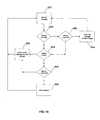
- FIG. 5is a flow diagram illustrating an example protocol stack in an apparatus for measurement, analysis, and optimization of content delivery according to an embodiment of the present invention
- FIGS. 6A-Eare flow diagrams illustrating an example root analyzer in an apparatus for measurement, analysis, and optimization of content delivery according to an embodiment of the present invention
- FIG. 7Ais a flow diagram illustrating an example session analyzer in an apparatus for measurement, analysis, and optimization of content delivery according to an embodiment of the present invention
- FIG. 7Bis a flow diagram illustrating an example server analyzer in an apparatus for measurement, analysis, and optimization of content delivery according to an embodiment of the present invention
- FIG. 7Cis a flow diagram illustrating an example application analyzer in an apparatus for measurement, analysis, and optimization of content delivery according to an embodiment of the present invention
- FIG. 7Dis a flow diagram illustrating an example page analyzer in an apparatus for measurement, analysis, and optimization of content delivery according to an embodiment of the present invention
- FIG. 7Eis a flow diagram illustrating an example page component analyzer in an apparatus for measurement, analysis, and optimization of content delivery according to an embodiment of the present invention
- FIG. 7Fis a flow diagram illustrating an example web site analyzer in an apparatus for measurement, analysis, and optimization of content delivery according to an embodiment of the present invention
- FIG. 8is a flow diagram illustrating an example data migration in an apparatus for measurement, analysis, and optimization of content delivery according to an embodiment of the present invention
- FIG. 9is a flow diagram illustrating an example data aggregation in an apparatus for measurement, analysis, and optimization of content delivery according to an embodiment of the present invention.
- FIG. 10is a block diagram illustrating an example data store manager of an apparatus for measurement, analysis, and optimization of content delivery according to an embodiment of the present invention
- FIG. 11is a block diagram illustrating an example reporting engine of an apparatus for measurement, analysis, and optimization of content delivery according to an embodiment of the present invention
- FIGS. 12A-Eare software application windows illustrating example interfaces for presenting reports and information in a system for measurement, analysis, and optimization of content delivery according to one embodiment of the present invention
- FIG. 13is a block diagram illustrating an example system for measurement, analysis, and optimization of content delivery according to an embodiment of the present invention
- FIG. 14is a block diagram illustrating an example home base component in a system for measurement, analysis, and optimization of content delivery according to an embodiment of the present invention
- FIG. 15is a flowchart illustrating an example process for processing data packets through a protocol stack according to an embodiment of the present invention
- FIG. 16is a flowchart illustrating an example process for identifying a page object from a set of application messages according to an embodiment of the present invention
- FIG. 17is a flowchart illustrating an example process for routing a data object to a sub-analyzer according to an embodiment of the present invention
- FIG. 18is a flowchart illustrating an example process for populating a data storage area with cache data according to an embodiment of the present invention.
- FIG. 19is a flow diagram illustrating an example process for switching data repositories during operation according to an embodiment of the present invention.
- Certain embodiments disclosed hereinprovide methods and apparatus for measurement, analysis and optimization of content delivery over a communications network.
- one apparatus disclosed hereindetects data packets on a network. These packets are read by the apparatus and as they are combined into high level application messages, certain user centric events are generated and stored for later analysis germane to the efficiency of content delivery over the network. Additionally, the user centric events are further correlated into groups directly relating to the experience of the end user, allowing metrics describing the end user experience to be stored. These metrics can also be analyzed to identify bottlenecks or errors in the delivery of content over a network. Additionally, the system can analyze the metrics and proactively provide notice of existing problems or take action to prevent potential problems.
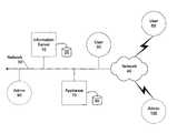
- FIG. 1is a block diagram illustrating a high level overview of an example system for measurement, analysis, and optimization of content delivery.
- the systemhas an information server 10 coupled with a data storage area 20 .
- Information server 10may incorporate various types of information servers including, for example, a world wide web (“WWW” or “web”) server that provides web pages upon request. Additionally, information server 10 may incorporate a file server that provides files upon request through a file transfer program, a remote copy program, or some other utility.
- WWWworld wide web
- webfile server that provides files upon request through a file transfer program, a remote copy program, or some other utility.
- the various types of information serversmay be integrated on a single general purpose computer or they reside on separate computers.
- information server 10may comprise a plurality of general purpose computers that provides a single service.
- a single web servermay employ multiple computers to disperse the massive amounts of content available to users across multiple processor units and data storage areas.
- information server 10may be a single general purpose computer that hosts a variety of discrete services. For example, a small web server, a file transfer server, or a real time data server.
- information server 10may provide voice over IP (“VoIP”) services.
- information server 10may provide video on demand (“VonD”) services.
- VoIPvoice over IP
- VonDvideo on demand
- the multiple types of information, data, and the variety of services that can be provided by information server 10are all contemplated within the scope of the present invention. However, for the purposes of this detailed description, information server 10 will be described in a web server embodiment in order to consistently and effectively describe the inner workings, features, and advantages of the present invention.
- Content deliveryembodies providing information or services to any client on demand.
- Content deliverymay also include each of the various components in the content delivery chain from end users to an information server.
- some componentsmay include end users, programmed devices, intelligent devices, communication networks (including any intervening networks between the end user and the information server), servers, applications, and databases, just to name a few.
- information server 10is connected to a communications network 30 .
- network 30can be a local area network (“LAN”) a wide area network (“WAN”), a public network, a private network, a virtual private network, a wired network, a wireless network, or various other types of communication networks.
- the function of network 30is to carry content between information server 10 and other devices communicatively coupled with information server 10 .
- Additional networksmay also be employed to carry content. For example, content delivered from information server 10 to users 50 and 60 may travel over network 30 and network 40 to reach its destination. Additional networks may also be involved in the function of carrying content.
- users 50 and 60may include actual persons using a general computing device and/or remote devices configured to query server 10 .
- Multiple appliancescan be at each location where an appliance is shown. Multiple appliances can be used to provide redundancy or to allow an administrator to dedicate each appliance to measure, analyze, and optimize particular sets of information servers as a convenience.
- appliance 70is situated on network 30 such that appliance 70 is capable of seeing all of the network traffic that is seen by information server 10 .
- appliance 70may be located on the same physical wire as information server 10 .
- appliance 70may be located between network 30 and information server 10 such that all network traffic seen by information server 10 must pass through appliance 70 .
- the function of the location of appliance 70is to ensure that appliance 70 sees all of the network traffic available to information server 10 .
- Appliance 70is preferably coupled with a data storage area 80 .
- Data storage area 80can be configured as a conventional database, a hierarchical file system, or many other viable alternatives for long term storage of information.
- data storage area 80can be configured as a lightweight directory access protocol (“LDAP”) database.
- LDAPlightweight directory access protocol
- Data storage area 80may be integrated within appliance 70 or alternatively, data storage area 80 may be external to appliance 70 .
- admin 90may be present on network 30 with information server 10 and appliance 70 .
- admin 90has the ability to communicate with appliance 30 over network 30 .
- admin 100may be located on a remote network 40 , although still communicatively coupled with appliance 70 via the combination of network 40 and network 30 , including any intervening networks.
- the function of admin 90is to communicate with appliance 70 and provide the ability to configure appliance 70 according to the desired performance of the system.
- FIG. 2is a flow diagram illustrating an example appliance 71 configured for measurement, analysis, and optimization of content delivery over one or more networks 31 and 41 .
- data packetssuch as DP 1 and DP 2 travel over networks 31 and 41 from source network appliances (not shown) to information server 11 and back.
- Data packets DP 1 and DP 2are representative of a significant number of data packets that, in aggregate, constitute the requests for and delivery of content by information server 11 , which is preferably coupled with data storage area 21 .
- Appliance 71coupled with data storage area 81 , is positioned on network 76 relative to information server 11 such that appliance 71 sees all of the network traffic (i.e. data packets DP 1 and DP 2 ) destined for the targeted information server 11 .
- appliance 71detects their presence and reads the data packets. The detection can be accomplished either actively or passively. Preferably, passive detection can be employed so as to reduce overall system overhead.
- this function of appliance 71may be implemented using a conventional packet capture device.
- a packet capture devicemay be implemented in hardware or software and performs the function of detecting and capturing data packets from a network as described above.
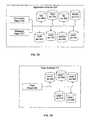
- FIG. 3is a block diagram illustrating an example appliance 72 for measurement, analysis, and optimization of content delivery.
- Appliance 72is preferably connected to a network (not shown) and coupled with a data storage areas 82 A and 82 B.
- the data storage areas 82 A and 82 Bmay be separate discrete storage areas or a single physical storage area logically separated into areas 82 A and 82 B.
- data storage area 82 Amay be a disk drive that stores a standard LDAP database and data storage area 82 B may be a cache that includes both memory storage area and disk storage area.
- data storage areas 82 A and 82 Bcollectively include memory, hard drive, removable hard drive, magneto-optical storage discs, and other fixed and removable storage mediums that can be either volatile or persistent.
- Appliance 72may be comprised of a data analyzer 110 , a data store manager 120 , a reporting engine 130 , an interface 140 , and an alert manager 800 .
- Data analyzer 110detects the packets on the network (not shown), reads the packets, and combines and correlates the data packets into application messages and user-centric events. These user centric events are then multiplexed into various logical groupings and stored in data storage areas 82 A and/or 82 B.
- the user centric eventscan be stored initially in data storage area 82 B, which comprises memory and a cache, and then later transitioned into long term storage area 82 A, which comprises an LDAP database.
- Data store manager 120controls the writing and reading of data to data storage areas 82 A and 82 B. Any data storage techniques employed by appliance 72 are implemented by data storage manager 120 in a fashion that simplifies the write and read operations of related components, such as data analyzer 110 . For example, data store manager 120 may encrypt, compress, or otherwise massage the data maintained in data storage areas 82 A and 82 B for optimized and efficient storage. This encryption or compression is advantageously hidden from any components reading or writing data to data storage area 82 A. In one embodiment, the data stored in long term storage area 82 A can be compressed while the data stored in cache storage area 82 B can be uncompressed.
- Reporting engine 130preferably accesses the data in data storage area 82 A or 82 B (through data store manager 120 ) and generates reports based on the raw data.
- reporting engine 130may access the data in long term data storage area 82 A in order to reduce overhead and allow cache storage area 82 B to continue to be used by data collection processes.
- reporting engine 130may automatically generate reports and/or generate reports upon request.
- the format of the reportsmay be standard or customized.
- the essential function of reporting engine 130is to read data from data storage areas 82 A or 82 B and recapitulate and format the data into a variety of reports that provide value and convey the nature of content delivery over a communications network.
- Alert manager 800preferably allows appliance 72 to modify the notification method used to inform a customer that a predefined or automatically defined threshold has been breached.
- a thresholdmay be set in a configuration file.
- a thresholdmay be set by the continuous operation of an appliance such that the threshold is automatically configured by the appliance to be a certain percentage above the mean.
- thisallows thresholds to be established for moving target type metrics such as page requests per hour.
- the applianceis able to calculate a mean number of page requests per hour, per minute, per day, or some other time related metric.
- the mean page requests between 9:30 am and 9:45 ammay be 1000.
- a thresholdmay be set so that the administrator is notified if the number of page requests exceeds the mean by 20%.
- alert manager 800may advantageously provide a notice message to an administrator or other designated party.
- alert manager 800may allow the method for notifying the administrator to change.
- the administratormay be notified by an entry written to a log file.
- the administratormay be notified via an email sent to the administrator's email address.
- the administratormay be notified via a pager or some other convenient and real time electronic notification method.
- Alert manager 800may also provide the ability to respond to a threshold notice by taking steps to fix a detected problem. For example, alert manager 800 may reboot the information server if necessary. Also, the appliance may be configured to make modifications to an information server so as to ensure that no major disruptions in content delivery are experienced by users of the information server.
- FIG. 4is a block diagram illustrating an example data analyzer 110 in an apparatus for measurement, analysis, and optimization of content delivery.
- Data analyzer 110can be connected to a data storage area 83 .
- data storage area 83can be a cache storage system that is comprised of both memory and disk space.
- Data analyzer 110is comprised of a protocol stack 150 and a root analyzer 160 .
- the protocol stack 150receives packets from a network and combines the packets into data objects that represent user centric events.
- Root analyzer 160receives the data objects, sorts them into coherent groupings, and condenses the data elements contained within the data objects for optimized long term storage.
- FIG. 5is a flow diagram illustrating an example protocol stack 151 in an apparatus for measurement, analysis, and optimization of content delivery.
- the protocol stack 151resides in a data analyzer (not shown) that is connected to a network 32 .
- Data packetssuch as DP 3 , travel across the network to and from information server 12 , which is coupled with a data storage area 22 . These data packets are read and processed by protocol stack 151 .
- Protocol stack 151can be comprised of a packet detector 170 , an IP layer 180 , a transport control protocol (“TCP”) layer 190 , a secure socket layer (“SSL”) decrypter 200 , an application selection layer 210 , and an application decoding layer 220 .
- Data packetssuch as DP 3 are read into protocol stack 151 and combined by protocol stack 151 to ultimately produce a data object 230 .
- the data objectis preferably comprised of several data elements.
- Packet detector 170preferably captures each and every packet traveling on the network 32 . Each packet that is captured by detector 170 is stored in a local buffer until it is moved into memory. As will be understood by those skilled in the art, commercial packet detectors carry out this function and can be integrated into the appliance to serve that limited purpose. An additional function of packet detector 170 is to apply a high resolution timestamp to each packet that is captured from network 32 . Once a packet is captured and timestamped by packet detector 170 , the packet is forwarded to IP layer 180 .
- IP layer 180operates much like an IP layer of a conventional TCP/IP protocol stack, although on a much broader and more complex scale. IP layer 180 performs all of the standard operations of a conventional IP layer such as IP header validation, IP compliance, IP checksum validation, IP multiplexing, and IP data segment defragmentation. However, as a conventional IP layer performs these operations on packets destined for the machine on which the IP layer is running, IP layer 180 processes all packets detected on the network by detector 170 , regardless of the destination.
- IP layer 180creates a unique flow object to track the current state of each unique source-destination tuple (source IP, destination IP). Once the flow object has been created, the flow object processes each subsequent packet detected that contains the source IP and destination IP of the flow's unique tuple. In this fashion, IP layer 180 can advantageously process all packets detected on the network. Packets that are processed by IP layer 180 are then forwarded on to TCP layer 190 .
- TCP layer 190operates much like a TCP layer of a conventional TCP/IP protocol stack, although on a much broader and more complex scale.
- TCP layer 190performs all of the standard operations of a conventional TCP layer such as TCP header validation, TCP compliance, TCP checksum validation, TCP connection selection (multiplexing), TCP data segment ordering, and TCP data segment re-assembly.
- TCP header validationTCP compliance
- TCP checksum validationTCP connection selection (multiplexing)
- TCP connection selectionmultiplexing
- TCP data segment orderingre-assembly.
- TCP layer 190performs these operations for both the client and the server in every connection.
- TCP layer 190maintains state information for both the client and the server in each unique client-server tuple (client IP, client port, server IP, server port). Additionally, the state changes detected by TCP layer 190 when processing datagrams received from IP layer 190 are passed along to the upper layers of the protocol stack 151 . Furthermore, the time of the state change is also determined by TCP layer 190 and passed through to the upper layers of the protocol stack 151 .
- TCP layer 190captures the time that the state changes occur. This information can preferably improve the later analysis of content delivery. For example, the elapsed time between the TCP_SYN_RECV state and the TCP_ESTABLISHED state provides the round trip network delay between the client and server.
- TCP layer 190provides the upper layers of protocol stack 151 with application data from both the client and the server, along with additional protocol information.
- TCP layer 180can additionally provide the length of the application data, the time when the application data was sent, and the time when the application data was acknowledged as received.
- TCP layer 190notifies the upper layers of protocol stack 151 when specific packets are transmitted. For example, TCP layer 190 passes through acknowledgement packets while conventional TCP layers do not. Datagrams that are processed by TCP layer 190 are then forwarded on to either SSL decrypt layer 200 or application layer 210 . Those datagrams that are encoded using the secure socket layer encryption are sent by TCP layer 190 to the SSL decrypt layer 200 . All other datagrams (including those that are not encoded and state change notifications) are passed along to application layer 210 .
- SSL decrypt layer 200serves the function of decrypting encrypted traffic. This layer can be implemented by a conventional SSL decryption tool or utility and may use a standard SSL decryption algorithm.
- protocol stack 151uses the wealth of information provided by the lowers layers of protocol stack 151 in conjunction with the application data provided by the lower layers. For example, TCP/IP state information and application data are correlated across multiple user sessions and connections to generate higher level descriptions of user, application, network, and server behavior.
- an HTTP web browsermay open up several simultaneous TCP connections. Each connection is then used to download a different component of the current page. As these components arrive at the client, the web browser application begins to render the web page on the display. Often, some of these TCP connections are kept open by the web browser application in anticipation of downloading a new page shortly after the current page.
- the FTP (file transfer) applicationuses a single TCP connection for issuing commands and a second TCP connection for transmitting the requested file. After the transfer is complete, the TCP connection for transmission is closed.
- each unique application decoding layercan have a similar structure consisting of a session processing layer, a connection processing layer, a message processing layer, and a content processing layer. Some application decoding layers may also have additional processing layers.
- Application selection layer 210allows protocol stack 151 to implement the various unique application decoding layers by identifying the appropriate application for the particular message received from TCP layer 190 or SSL decryption layer 200 and routing those messages to the corresponding application decoding layer 220 .
- the particular application decoding layermay be identified by the TCP server port for the connection.
- this informationis passed to application selection layer 210 from TCP layer 190 or SSL decryption layer 200 and thus it is contained within the message.
- non-standard port numbersmay be assigned to the various applications.
- the appliancemay be configured to recognize the non-standard port numbers.
- the appliancemay be configured to dynamically decipher the application associated with a particular port number.
- each application decoding layermay comprise a separate layer to process the various types of objects it may receive.
- the application decoding layermay comprise a session layer, a connection layer, a message layer, a content layer, and a content component layer in order to efficiently process session objects, connection objects, message objects, content objects, and content component objects.
- a session objectmay comprise user level events.
- a session objectcan be created for each interaction between a user and an information server.
- the session objectmay comprise data elements describing the user's overall experience with the application running on the information server(s).
- a connection objectmay comprise transport level events.
- one or more TCP connectionscan be opened with one or more information servers during the course of a session.
- a connection objectcan be created.
- the connection objectcomprises data elements that describe the overall performance and behavior of connections to an information server.
- a message objectmay comprise requests and responses made to an information server.
- one or more requestscan be sent to an information server during the course of a session.
- one or more responsescan be sent back to the requesting client.
- a requestmay contain a command or action to be performed by the information service, while a response may contain the result of performing the requested action.
- a request message objectcan be created that comprises the type of request, the specific action, and the target of the action.
- additional detailsmay be added to the object by other application decoding layers.
- a response message objectcan be created that comprises the type of response, the success or failure of the request, and any resulting data that is to be returned to the requester. Again, additional details may be added by other application decoding layers.
- a content objectmay comprise the high-level resources, data, information, or services provided by an information server.
- each resourcemay have a unique name or identifier.
- a content objectcan be created that comprises the resource type, identity, size, availability, structure, and organization of the content.
- additional detailsmay be added by the other application decoding layers.
- a content component objectmay comprise a sub-part of the content provided by the information service.
- an information servermay break content up into various sub-components.
- a web page provided by a web servermay include dozens of images, many applets, and various other multi-media component.
- a content component objectcan be created that comprises data elements describing the component type, identity, size, availability, structure, and organization. Additional details may be added to the content component object by the other application decoding layers.
- Application decoding layer 220may comprise four layers, namely the session processing layer, the connection processing layer, the message processing layer and the content processing layer.
- the session processing layerprovides for tracking how each user is interacting with a monitored web site.
- the session processing layercorrelates events from every connection to provide a high level view of how information server 12 is being used.
- the session processing layerproduces session objects as output.
- object 230could be a session object.
- a unique session objectis created for each unique client IP address that is received.
- all events and messagescontain the client IP address so they can be correctly identified.
- each subsequent event and message that contains the same client IP addressis forwarded to the appropriate session object.
- a session objectpreferably contains data elements that describe the various aspects of a user's session with information server 12 . When complete, a session object is forwarded to the root analyzer for further processing and storage.
- a session objectmay include data elements reflecting the number of user clicks, the number of pages downloaded, average download time, download time per page, cumulative download time, session length (how long the user was on the site), average network delay between client and server, client access speed (slowest link in connectivity), number of application messages sent/received by user, size of application messages sent/received by user, type and number of application requests made by user, number and size of data packets sent/received by user, and number and size of TCP segments sent/received by user.
- connection processing layerproduces connection objects as output.
- object 230could be a connection object.
- a connection objectcontains various data elements that describe the various aspects of a single connection between a single user (not shown) and information server 12 .
- a connection objectcan be uniquely identified by the tuple (client IP, client Port, server IP, server Port).
- this informationis propagated up protocol stack 151 by the lower layers.
- a connection objectis forwarded to the root analyzer for further processing and storage.
- a connection objectmay include data elements reflecting the number of open connections, the number of request messages, server response time, number of successful requests, number of failed requests, network delay from the server to the end user, connection terminated by the end user or server, number of TCP segments exchanged between client and server, number of packets exchanged between end user machine and the server.
- the message processing layerproduces message objects as output.
- types of message objectsmay include request message objects and response message objects.
- object 230could be a request message object or a response message object.
- the function of the message processing layeris to extract application specific data elements from each message.
- the message processing layeradvantageously determines whether the message is a request from the client to the server or whether the message is a response from the server to the client.
- the serversends a response message for every request message.
- the message processing layermay determine the command type (e.g., GET, PUT, POST, HEAD, etc.), the uniform resource locator (“URL”), the referrer, and the host (server). This data can preferably be stored in the request message object.
- command typee.g., GET, PUT, POST, HEAD, etc.
- URLuniform resource locator
- the referrerthe referrer
- serverthe host
- the message processing layermay determine the response code (success, server error, client error, redirect, informational), the content type (text, binary), the content encoding (compressed, uncompressed, uuencoded, etc.), and the last time modified, to name just a few.
- a request or response message objectFor both the HTTP request and HTTP response, many other application specific data elements may be extracted. The details about each message can be stored in a request or response message object. When complete, a request or response message object is forwarded to the root analyzer for further processing and storage.
- a message objectmay include data elements reflecting the number and size of packets sent/received by the user, the number and size of TCP segments sent/received by the user, the number of packets required to transmit a message, number of segments required to transmit a message, request type (GET, PUT, POST, HEAD), request URL, Referrer, response type (Success, Client Error, Server Error, etc.), content type, content encoding, and the like.
- the content processing layerproduces content and content component objects as output.
- object 230could be a content object or a content component object.
- the function of the content processing layeris to use information from all other layers (session, connection, message, and the lower networking layers) to extract high-level representations of the data, information, services, and other resources provided by an information server. The type and structure of the content is different for every application.
- HTTP content provided by a web information servercan be represented as a page object.
- the contentcan be also be sub-divided into page components.
- a page object or page component objectis forwarded to the root analyzer for further processing and storage.
- a content objectmay include data elements reflecting the URL of a page, number of page downloads, number of page components in a page, number of pages successfully downloaded, number of pages unsuccessfully downloaded, time to download a complete page, size of the entire page, number of packets to download a complete page, number of segments to download a complete page, number of connections opened to download a page, and the number of pages stopped for download by the end user.
- a content component objectmay include data elements reflecting the Page component object reflecting the Uniform Resource Locator (URL) of a page, number of page component downloads, number of components successfully downloaded, number of components unsuccessfully downloaded, time to download a page component, size of the page component, number of packets to download a page component, and the number of segments to download a page component.
- URLUniform Resource Locator
- FIGS. 6A-Eare flow diagrams illustrating example root analyzers 161 - 164 in an apparatus for measurement, analysis, and optimization of content delivery.
- the function of the root analyzeris to discern the type of object received from the protocol stack and then route that object to one or more appropriate sub-analyzers.
- root analyzer 161has various sub-analyzers including session analyzer 280 , server analyzer 290 , application analyzer 300 , page analyzer 310 , page component analyzer 320 , and web site analyzer 330 . Additional sub-analyzers may be added to handle different types of specialized objects. These analyzers preferably handle the various types of data objects, such as object 231 , that are passed to root analyzer 161 .
- the function of the various sub-analyzerscan advantageously be to analyze one or more objects created by the protocol stack and create or update the appropriate storage area that may be later viewed by an end-user of the appliance.
- the various sub-analyzerscan use identifying field values in the object to correctly select the particular storage area to update.
- a storage areamay comprise a plurality of external objects.
- External objectscan be those objects in a longterm storage area (e.g., a database). Preferably, the longterm storage area is accessible to users of the appliance via an interface.
- external objectscan map directly to elements in the service delivery chain for an information server. Examples of external objects include server objects, application objects, user session objects, network objects, web-site objects, and web page objects.
- an external server objectcan be created for each information server providing a service. Additional objects specific to an information server's delivery chain may also be included.
- an external web page objectcan be specific to the web information server.
- External objectscan be created by the various sub-analyzers.
- Sub-analyzersuse objects received from the protocol stack to construct external objects.
- an external objectcan be an aggregation of all the internal objects used in its creation.
- FIG. 6Aillustrates a session object being sent to root analyzer 161 .
- root analyzer 161Upon receiving object 231 and determining that the object is a session object 240 , root analyzer 161 passes session object 240 to session analyzer 280 for further processing and storage.
- the other sub-analyzers(server, application, page, page component, and web site) do not receive session objects.
- root analyzer 162receives object 232 and determines that it is a connection object 251 . Upon determining the type of object, root analyzer 162 passes connection object 251 to session analyzer 281 , server analyzer 291 , application analyzer 301 , and web site analyzer 331 .
- connection object 251may contain data elements germane to each of the sub-analyzers that it is passed to. Page analyzer 311 and page component analyzer 321 do not receive connection objects.
- root analyzer 163receives object 233 and determines that it is a page object 262 . Upon determining the type of object, root analyzer 163 passes page object 262 to session analyzer 282 , server analyzer 292 , page analyzer 312 , and web site analyzer 332 .
- page object 262may contain data elements germane to each of the sub-analyzers that it is passed to.
- Application analyzer 302 and page component analyzer 322do not receive page objects.
- root analyzer 164receives object 234 and determines that it is a page component object 273 . Upon determining the type of object, root analyzer 164 passes page component object 273 to page component analyzer 323 and web site analyzer 333 .
- page component object 273may contain data elements germane to each of the sub-analyzers that it is passed to. Session analyzer 283 , server analyzer 293 , application analyzer 303 , and page analyzer 313 do not receive page component objects.
- root analyzer 164receives object 234 and determines that it is a message object 249 . Upon determining the type of object, root analyzer 164 passes message object 249 to server analyzer 293 and application analyzer 303 .
- message object 273may contain data elements germane to each of the sub-analyzers that it is passed to. Session analyzer 283 , page analyzer 313 , page component analyzer 323 , and web site analyzer 333 do not receive message objects.
- FIG. 7Aillustrates a session analyzer 284 , which may receive data objects of type session object 244 , connection object 254 , or page object 264 .
- session analyzer 284stores the data elements from all of the data objects it receives in a single summary record 340 , rather than creating a new record for each unique session.
- thishelps to manage the growth of data and also provides a unique, cumulative user session profile that characterizes the average user session with the information server.
- FIG. 7Billustrates a server analyzer 294 , which may receive data objects of type connection object 255 , page object 265 , and message object 276 . Because a single apparatus may monitor one or more servers (or one or more applications on one or more servers) there can be a server record for each information server being tracked.
- server analyzer 294may have a server 1 record 350 , a server 2 record 360 , and a server n record 370 . The presence of server n record 370 indicates that there may be additional server records.
- server analyzer 294may maintain a summary record 341 .
- server analyzer 294When server analyzer 294 receives a data object such as connection object 255 , page object 265 , or message object 276 , it can parse the object to determine which server the object is associated with.
- this informationis contained in the object as constructed by the protocol stack.
- server analyzer 294may determine the server by the IP address data element contained in the data object.
- server analyzer 294can store the relevant data elements from the data object in the identified record.
- server analyzer 294can store data elements from the data object in the summary record 341 .
- FIG. 7Cillustrates an application analyzer 304 , which may receive data objects of type connection object 256 and message object 277 . Because a single apparatus may monitor one or more applications there can be an application record for each application being tracked.
- application analyzer 304may have an HTTP record 380 , an HTTPS record 390 , an FTP record 400 , a streaming media record 410 , a VoIP record 420 , a VonD record 430 , and a record for any of the various other applications that may be monitored by application analyzer 304 , as illustrated by the presence of application record 440 .
- application analyzer 304may maintain a summary record 342 .
- application analyzer 304When application analyzer 304 receives a data object such as connection object 256 or message object 277 , it preferably parses the object to determine which application the object is associated with. Advantageously, this information is contained in the object as constructed by the protocol stack. For example, application analyzer 304 may determine the associated application by the well known TCP Port data element contained in the data object. Upon determining the appropriate record for the object, application analyzer 304 preferably stores the relevant data elements from the data object in the identified record. In addition, application analyzer 304 can store data elements from the data object in the summary record 342 .
- FIG. 7Dillustrates a page analyzer 314 , which may receive data objects of type page object 266 .
- page analyzer 314may have a page 1 record 450 , a page 2 record 460 , a page 3 record 470 , and a record for any of the various other pages that may be hosted by an information server and monitored by page analyzer 314 , as illustrated by the presence of page n record 480 .
- page analyzer 314may maintain a summary record 343 .
- page analyzer 314When page analyzer 314 receives a data object such as page object 266 , it preferably parses the object to determine which page the object is associated with. Advantageously, this information is contained in the object as constructed by the protocol stack. For example, page analyzer 314 may determine the associated page by the URL data element contained in the data object. Upon determining the appropriate record for the object, page analyzer 314 preferably stores the relevant data elements from the data object in the identified record. In addition, page analyzer 314 can store data elements from the data object in the summary record 343 .
- FIG. 7Eillustrates a page component analyzer 324 , which may receive data objects of type page component object 274 .
- page component analyzer 324may have a component 1 record 490 , a component 2 record 500 , a component 3 record 510 , and a record for any of the various other components that may be monitored by page component analyzer 324 , as illustrated by the presence of component n record 520 .
- page component analyzer 324may maintain a summary record 344 .
- page component analyzer 324When page component analyzer 324 receives a data object such as page component object 274 , it preferably parses the object to determine which component the object is associated with. Advantageously, this information is contained in the object as constructed by the protocol stack. For example, page component analyzer 324 may determine the associated component by the URL data element contained in the data object. Upon determining the appropriate record for the object, page component analyzer 324 preferably stores the relevant data elements from the data object in the identified record. In addition, page component analyzer 324 can store data elements from the data object in the summary record 344 .
- FIG. 7Fillustrates a web site analyzer 334 , which may receive data objects of type connection object 257 , page object 267 , and page component object 275 . Because a single apparatus may monitor a large number of web sites, there can be a web site record for each web site being monitored by the information server. For example, web site analyzer 334 may have a site 1 record 530 , a site 2 record 540 , a site 3 record 550 , and a record for any of the various other web sites that may be monitored by web site analyzer 334 , as illustrated by the presence of site n record 560 . In addition, web site analyzer 334 may maintain a summary record 345 .
- web site analyzer 334When web site analyzer 334 receives a data object such as connection object 257 , page object 267 , or page component object 275 , it preferably parses the object to determine which component the object is associated with.
- this informationis contained in the object as constructed by the protocol stack.
- web site analyzer 334may determine the web site by the URL data element contained in the data object, or a combination of the IP address data element and the TCP Port data element.
- web site analyzer 334Upon determining the appropriate record for the object, web site analyzer 334 preferably stores the relevant data elements from the data object in the identified record.
- web site analyzer 334can store data elements from the data object in the summary record 345 .
- the various sub-analyzersstore data elements in various records. These records preferably exist in a cache data storage area available to the data analyzer. As the records begin to accumulate, the data analyzer preferably employs data migration to manage the growth of the data while maintaining the detail rich information being collected.
- FIG. 8is a flow diagram illustrating an example data migration in an apparatus for the measurement, analysis, and optimization of content delivery.
- all of the datais stored in the real time database 570 .
- the real time database 570becomes full, the data is aggregated into the hourly series database 580 .
- aggregating the datamaintains the level of detail represented by the data while at the same time significantly reducing the necessary storage space required to maintain that detailed information.
- the hourly series database 580As the hourly series database 580 accumulates data, the data stored therein is periodically aggregated into various additional databases including the hourly longterm database 590 , the daily series database 600 , the daily longterm database 610 , the weekly series database 620 , the monthly series database 630 , the monthly longterm database 640 , and the yearly series database 650 .
- the periodic nature of the aggregation from the hourly series database 580 to the various other databasescan be hourly, as suggested, or some other period more closely tailored to the efficient operation of the system. Since aggregations may take processor time and cause disk accesses, it may be advantageous to increase or decrease the period.
- FIG. 9is a flow diagram illustrating an example data aggregation in an apparatus for measurement, analysis, and optimization of content delivery.
- the advantage of aggregating datais twofold: first, the space required to house the data is reduced; and second, the rich detail of the data is maintained.
- the storage area allocated to real time database 571begins to wane.
- real time database 571may store server data in records S 1 and S 2 . This represents the data that has been accumulated during the current period for real time database 571 .
- This datarequires a certain amount of storage area to hold data elements S 1 : a , S 1 : b , S 1 : c , S 2 : a , S 2 : b , and S 2 : c .
- hourly series database 581contains server data and already includes a data record S 1 . Therefore, data elements S 1 : a , S 1 : b , and S 1 : c already exist in hourly series database 581 . However, hourly series database 581 does not contain a data record S 2 , and it does contain a data record S 3 .
- hourly series database 582(the updated version of hourly series database 581 ) contains data records S 1 , S 2 , and S 3 .
- the hourly series database 582contains a new data record
- the size of hourly series database 582was increased by only a single data record (S 2 ) while two data records S 1 and S 2 were aggregated into hourly series database 582 .
- the new values in data record S 1have increased to reflect the data added from real time database 571 . This maintains the detail rich data collected by the apparatus while reducing the overall size of the data needed to be maintained.
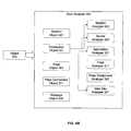
- FIG. 10is a block diagram illustrating an example data store manager 121 of an apparatus for measurement, analysis, and optimization of content delivery.
- the data store manager 121may be comprised of a populator 660 , a database manager 670 , and an external interface 680 . Additionally, data store manager 121 has access to data storage areas 84 A and 84 B.
- data storage areas 84 A and 84 Bmay be a single data storage area as previously described with reference to FIG. 3 .
- data storage area 84 Ais used for long term storage while data storage area 84 B is used for near term storage.
- data storage area 84 Bmay be a cache comprising both memory and disk space. Alternatively, the cache may comprise only memory or only disk space.
- data storage area 84 Amay comprise a standard database system such as an LDAP database.
- populator 660periodically reads data from cache 84 B and passes the data to database manager 670 .
- database manager 670receives the data from populator 660 and writes the data to longterm storage in data storage area 84 A.
- database manager 670In order to manage the exponential growth of data being written to data storage area 84 A, database manager 670 employs a purging method to limit the growth.
- the long term data storage area 84 Apreferably contains the same type of information that is maintained in cache 84 B. However, as the data in cache 84 B is aggregated by the data analyzer, the rich detail of the data being collected is propagated into the various databases contained in the data storage area, as described with reference to FIGS. 8 and 9 . Therefore, database manager 670 preferably periodically purges the potentially huge amounts of data stored in the real time database in data storage area 84 A.
- data from the real time databaseis aggregated into the hourly series database every 5 minutes.
- data from the hourly series databaseis aggregated into the hourly longterm database every hour.
- the database managermay purge this obsolete data and thereby manage the controlled growth of the data in long term data storage area 84 A. The method by which this is accomplished will be subsequently described with reference to FIG. 19 .
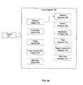
- FIG. 11is a block diagram illustrating an example reporting engine 131 of an apparatus for measurement, analysis, and optimization of content delivery.
- Reporting engine 131may be comprised of a presentation manager 690 , a configuration manager 700 , an alarm manager 710 , and a measure data manager 730 .
- the function of the reporting engineis to accept requests or use a predetermined configuration to generate reports outlining the measurements collected by the apparatus.
- reporting engine 131may periodically extract data from the data storage area and organize that data based on requested report types. This advantageously allows the reporting engine to spread its processor use out over a period of time. Advantageously, this eliminates the need for intensive processor use when generating the complete reports.
- Presentation manager 690is responsible for providing various views of the data contained in an apparatus for measurement, analysis, and optimization of content delivery.
- tabular and graphical views of datacan be provided. These views present real-time, hourly, daily, weekly, monthly and yearly data to the user.
- the apparatusmay provide these views using the hypertext markup language (“HTML”), and extensible markup language (“XML”) technologies. Users may access these presentations with a common web browser application residing on a computer system or with alternative devices that have network access to the apparatus.
- Presentation manager 690may also incorporates security mechanisms to ensure that only authorized users can gain access to the views presented. In one embodiment, presentation manager 690 may provide mechanisms by which users can configure and customize various aspects of both graphical and tabular reports.
- Configuration manager 700preferably allows one or more configuration files to be created, deleted, and modified. These configuration files are preferably used by reporting engine 131 to construct one or more customized reports containing the information desired by the administrator or user of the apparatus. In one embodiment, standard reports may include trend information and alarm threshold notifications.
- Alarm manager 710can monitor the data being collected by the system and compare the statistical output of the data collections to certain established thresholds. At any point in time when the statistical output of the data collections exceeds an established threshold for a particular metric, alarm manager 710 preferably takes the appropriate action.
- Actions taken by the alarm managercan include simple notification of an administrator that the threshold has been exceeded. This notification may take place by merely writing a notice to a log file. Alternatively, alarm manager 710 may send an email to an administrator to effectuate notice. Additional methods of providing notice are also contemplated, for example alarm manager 710 may cause a page to be sent to the administrator.
- alarm manager 710may also proactively initiate steps to fix the problem. For example, alarm manager 710 may detect, through certain thresholds being exceeded, that the information server process has abnormally terminated. In such a case, alarm manager 710 may proactively initiate the appropriate steps for rebooting the information server machine, re-initializing the information server process, or both.
- Measure data manager 730is responsible for querying, extracting, filtering and formatting data for presentation manager 690 in an apparatus for measurement, analysis, and optimization of content delivery.
- Presentation manager 690transmits requests to measure data manager 730 whenever a user action triggers the need to build a view for presentation.
- a requestcan specify which measurements are required, and how the data should be queried and formatted.
- a usercan specify a query that generates a view displaying the slowest ten web pages on a web site.
- queriesprovide users with the ability to interactively analyze and correlate the data contained in the data storage area. By performing extensive on-line analysis in this manner, the user is able to gauge all aspects of network performance, to troubleshoot current problems, and to perform proactive investigations aimed at preventing potential problems in the future.
- FIGS. 12A-Eare software application windows that illustrate example interfaces for presenting reports and information according to one embodiment of the present invention. These example windows are presented to show the rich value added by the characteristics of the particular presentations of the information collected by the apparatus.
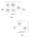
- FIG. 13is a block diagram illustrating an example system for measurement, analysis, and optimization of content delivery.
- the systemmay be comprised of an information server 13 coupled with a data storage area 23 , an appliance 73 coupled with a data storage are 85 , one or more users 51 , and one or more administrators 91 and 101 .
- these componentsare communicatively coupled over one or more networks such as network 33 and network 42 .
- appliance 73can be physically located such that it sees all of the data traffic traveling on network 33 that is seen by information server 13 .
- the systemmay include a home base 740 coupled with a data storage area 750 .
- home base 740is communicatively coupled with appliance 73 over one or more networks such as network 42 and network 33 .
- the function of home base 740can be to manage one or more remote appliances 73 , and provide account validation and status monitoring services.
- FIG. 14is a block diagram illustrating an example home base 741 in a system for measurement, analysis, and optimization of content delivery.
- Home base 741may be comprised of an auto update module 760 , an agent controller 770 , a messaging module 780 , and an account validation module 790 . Additionally, home base 741 may preferably be configured with a data storage area 751 .
- Auto update module 760may allow home base 741 to keep remote appliances up to date with the most current version of operational programs and data. For example, an appliance in communication with home base 741 may indicate that the appliance is running an older version of the appliance software.
- auto update module 760can detect this and upgrade the appliance software over the network. Additionally, auto update module may determine if new appliance distribution files are necessary, and if so, transfer those files to the remote appliance.
- Agent controller 770preferably provides the home base 741 unit with remote control over the appliances in communication with home base 741 .
- agent controller 770may transfer files to and from the remote appliance. Additionally, agent controller 770 may reboot a remote appliance.
- Messaging module 780preferably manages the receipt and sending of messages, files, and other data between home base 741 and any remote appliance. Upon receiving an incoming message, messaging module 780 preferably routes the message to the appropriate module within home base 741 .
- Account validation module 790can function to verify account information related to particular customers that have an appliance in operation. For example, a remote appliance may send a status inquiry to home base 741 to determine if the customer account is up to date. Account validation module 790 preferably consults data storage area 751 and responds to the query.
- FIG. 15is a flowchart illustrating an example process for processing data packets through a protocol stack according to an embodiment of the present invention.
- a packetis detected on the network.
- This functioncan be implemented by a packet detector.
- packet detectorAs will be understood by those skilled in the art various types of packet detectors may be employed.
- the packet detectoris robust and is capable of detecting and reading each packet on the network.
- the packetis sent to the IP layer of the protocol stack. This may be done by the packet detector migrating data from its internal buffers into standard memory. Once in memory, the IP layer can process the data packets. Advantageously, the IP layer can process packets for more than one IP address, unlike conventional protocol stacks. Furthermore, the IP layer preferably passes additional information about the packets up the protocol stack for use in the higher levels. As shown in step 814 , the IP layer passes the processed datagrams to the TCP layer.
- the TCP layerprocesses the datagrams received from the IP layer.
- the TCP layeris also capable of handling datagrams for more than one IP address.
- the TCP layeradvantageously can process datagrams for multiple connections between multiple clients and multiple servers.
- detail rich data relating to the requests for, delivery of, and processing of contentcan be passed from the TCP layer to the higher levels of the protocol stack, in addition to the data content.
- the TCP layercan detect if the data content is encrypted. If the content is encrypted, as determined in step 816 , the message is sent to the SSL layer for decryption, as illustrated in step 818 . Once decrypted, or if the data content was not encrypted, the message is sent to the higher levels of the protocol stock for further processing.
- the protocol stackcan process messages for a variety of applications including HTTP web browsers, FTP, VoIP, VonD, streaming media, and the like. Therefore, messages from the TCP layer or unencrypted messages from the SSL layer are passed to an application selection layer, as shown in step 820 .
- the application selection layerpreferably determines the application associated with the current message being processed and routes that message to the appropriate application decoding layer. For example, in step 822 the application selection layer determines what application is associated with the message. This may be carried out by examining the well known port number associated with the message. As previously described, well known port numbers are often associated with particular applications. Once the application has been determined, the message can be sent to the appropriate application decoding layer, as shown in step 824 .
- the application decoding layermay comprise one or more separate layers to process messages. Because each different application may use the underlying TCP connections in a variety of different ways, an application decoding layer will typically be unique for each specific application. Advantageously, this can be accommodated through the use of the application selection layer. Once the application decoding layer obtains an application message it preferably processes the message.
- the application decoding layermay advantageously combine messages in a fashion that allows the application decoding layer to determine metrics relating to the actual experience of the end users. For example, a complete page download time may be determined by adding up the download times for each of the various components of a single web page.
- the result of this type of processing by the application decodingis the creation of a data object that contains various data elements germane to the application and the application messages processed.
- the data objectcan then be associated with like data objects to ultimately provide metrics that describe in real terms relating to actual user experiences how the information server system is performing. Additionally, certain bottlenecks may be identified in the content delivery process such that the process may be continuously refined and improved.
- FIG. 16is a flowchart illustrating an example process for identifying a page object from a set of application messages according to an embodiment of the present invention.
- the continuous processobtains the next message in the stream of messages being received.
- Each message processed by the systemis checked to determine if it may be the message that starts a new page object.
- a logical separationmay be made between messages associated with a particular page. In order to determine this demarcation, each message in the stream must be reviewed.
- the URL data element in the messagecan be examined to determine if the message is from a client. If no URL data element exists, then the message can be excluded from the process.
- the next stepis to consult a message holding area to determine if a previous message is being held, as illustrated in step 832 . If no previous message is being held, the system examines the REFERRER data element, which contains the URL of the referring web page. If the REFERRER data element is NULL, then the current message is the start of a new page, and the message can be marked as indicated in step 836 .
- the REFERRER data elementis examined to determine if it contains a local URL. If the URL is not local, then the current message is the start of a new page, and the message can be marked as indicated in step 836 .
- step 832a message is in the holding area so the REFERRER data element of the current message is examined. This value is compared to the URL data element of the held message. If the URL data element of the held message is the same as the URL contained in the REFERRER data element of the current message, then the held message is the start of a new page, and the held message can be marked as indicated in step 844 .
- the REFERRER data element of the current messageis not matched, then the REFERRER data element is examined to see if it is NULL. If the value is NULL, then the current message is the start of a new page, and the message can be marked as indicated in step 836 .
- the data elementis examined to determine if the URL content refers to a local web page. If it does not, then the current is the start of a new page, and the message can be marked as indicated in step 836 .
- the current messagereplaces the message in the holding area and the process continues. In this fashion, as the messages continuously pass through the system, they can be examined to logically differentiate the messages into discrete web pages. As will be understood by those skilled in the art, once the start of page has been identified, the end of the previous page has correspondingly been identified.
- FIG. 17is a flowchart illustrating an example process for routing a data object to a sub-analyzer according to an embodiment of the present invention.
- the root analyzerreceives the data object from the protocol stack.
- the root analyzerdetermines the type of data object that has been received. For example, in one embodiment, the root analyzer may receive data objects of type session, connection, page, and page component. Once the type of data object has been determined, the root analyzer routes the data object to the one or more appropriate sub-analyzers, as shown in step 854 .
- the routing correlation between data objects and sub-analyzersmay be unique for each separate application.
- FIG. 18is a flowchart illustrating an example process for populating a data storage area with cache data according to an embodiment of the present invention.
- the data populatorprovides the function of transitioning data out of the cache and into longterm storage. Although the populator does not write data to long term storage, it passes the data to a database manager that determines how and where to write the data. For example, the populator first reads data from the cache, as shown in step 860 . Upon reading the data from the cache, the populator forwards the data to the database manager as illustrated in step 862 .
- the populator processhas less priority than the data collection process so at times reading step 860 may be postponed or delayed while the higher priority data collection process is executed.
- the populator processmay be periodically suspended and then re-activated in order to carry out its task.
- FIG. 19is a flow diagram illustrating an example process for switching data repositories during operation according to an embodiment of the present invention.
- the database managerreceives data from the populator, as described above with relation to FIG. 18 , the database manager writes that data into longterm storage in the database. However, much of the data received by the database manager is short term data that has been collected to reflect real time metrics of the system being monitored.
- the database managerperiodically purges the fastest growing databases.
- the fastest growing databasesmay include the real time database, the hourly series database, and the daily series database.
- the various longterm databasesare not subject to such rapid growth because the potential number of database records is finite.
- the hourly longterm databasecan typically have only 24 records, since there are only 24 hours in a day.
- the weekly longterm databasemay have only 7 records, one for each day in the week.
- the database managermay employ two separate repositories for a single database.
- the active repositorymay be DB 1
- the inactive repositorymay be DB 2 .
- the database managermay delete any residual data in DB 2 and set the active repository to be DB 2 . Any subsequent database writes during time period 2 are directed to this repository.
- the database managermay purge the data from repository DB 1 and set the active repository to be DB 1 . This process may continue through additional time periods such as time period 3 and time period 4 .
- the predetermined switch timesmay also be configurable, as well as variable.
- the predetermined switch timemay be set for the time when the current repository reaches 99% of capacity. This advantageously can reduce the required number of repository changes and reduce the overall overhead of the database management system.
- the switch timemay be appropriately set such that no data is purged from the inactive repository until enough time has passed to ensure that the detail included in the data has been aggregated into other long term storage, such as hourly longterm, daily longterm, or monthly longterm.
Landscapes
- Engineering & Computer Science (AREA)
- Signal Processing (AREA)
- Computer Networks & Wireless Communication (AREA)
- Computer Security & Cryptography (AREA)
- Physics & Mathematics (AREA)
- General Engineering & Computer Science (AREA)
- Computer Hardware Design (AREA)
- Algebra (AREA)
- General Physics & Mathematics (AREA)
- Mathematical Analysis (AREA)
- Mathematical Optimization (AREA)
- Mathematical Physics (AREA)
- Probability & Statistics with Applications (AREA)
- Pure & Applied Mathematics (AREA)
- Data Exchanges In Wide-Area Networks (AREA)
Abstract
Description
Claims (14)
Priority Applications (5)
| Application Number | Priority Date | Filing Date | Title |
|---|---|---|---|
| US09/850,877US6928471B2 (en) | 2001-05-07 | 2001-05-07 | Method and apparatus for measurement, analysis, and optimization of content delivery |
| PCT/US2002/014326WO2002091296A2 (en) | 2001-05-07 | 2002-05-06 | Method and apparatus for measurement, analysis, and optimization of content delivery |
| US11/198,019US7565336B2 (en) | 2001-05-07 | 2005-08-04 | Method and apparatus for measurement, analysis, and optimization of content delivery |
| US11/198,912US7539655B2 (en) | 2001-05-07 | 2005-08-04 | Method and apparatus for measurement, analysis, and optimization of content delivery |
| US12/500,109US7941385B2 (en) | 2001-05-07 | 2009-07-09 | Method and apparatus for measurement, analysis, and optimization of content delivery |
Applications Claiming Priority (1)
| Application Number | Priority Date | Filing Date | Title |
|---|---|---|---|
| US09/850,877US6928471B2 (en) | 2001-05-07 | 2001-05-07 | Method and apparatus for measurement, analysis, and optimization of content delivery |
Related Child Applications (2)
| Application Number | Title | Priority Date | Filing Date |
|---|---|---|---|
| US11/198,912ContinuationUS7539655B2 (en) | 2001-05-07 | 2005-08-04 | Method and apparatus for measurement, analysis, and optimization of content delivery |
| US11/198,019ContinuationUS7565336B2 (en) | 2001-05-07 | 2005-08-04 | Method and apparatus for measurement, analysis, and optimization of content delivery |
Publications (2)
| Publication Number | Publication Date |
|---|---|
| US20020173857A1 US20020173857A1 (en) | 2002-11-21 |
| US6928471B2true US6928471B2 (en) | 2005-08-09 |
Family
ID=25309350
Family Applications (4)
| Application Number | Title | Priority Date | Filing Date |
|---|---|---|---|
| US09/850,877Expired - LifetimeUS6928471B2 (en) | 2001-05-07 | 2001-05-07 | Method and apparatus for measurement, analysis, and optimization of content delivery |
| US11/198,912Expired - LifetimeUS7539655B2 (en) | 2001-05-07 | 2005-08-04 | Method and apparatus for measurement, analysis, and optimization of content delivery |
| US11/198,019Expired - LifetimeUS7565336B2 (en) | 2001-05-07 | 2005-08-04 | Method and apparatus for measurement, analysis, and optimization of content delivery |
| US12/500,109Expired - Fee RelatedUS7941385B2 (en) | 2001-05-07 | 2009-07-09 | Method and apparatus for measurement, analysis, and optimization of content delivery |
Family Applications After (3)
| Application Number | Title | Priority Date | Filing Date |
|---|---|---|---|
| US11/198,912Expired - LifetimeUS7539655B2 (en) | 2001-05-07 | 2005-08-04 | Method and apparatus for measurement, analysis, and optimization of content delivery |
| US11/198,019Expired - LifetimeUS7565336B2 (en) | 2001-05-07 | 2005-08-04 | Method and apparatus for measurement, analysis, and optimization of content delivery |
| US12/500,109Expired - Fee RelatedUS7941385B2 (en) | 2001-05-07 | 2009-07-09 | Method and apparatus for measurement, analysis, and optimization of content delivery |
Country Status (2)
| Country | Link |
|---|---|
| US (4) | US6928471B2 (en) |
| WO (1) | WO2002091296A2 (en) |
Cited By (75)
| Publication number | Priority date | Publication date | Assignee | Title |
|---|---|---|---|---|
| US20030105877A1 (en)* | 2000-11-14 | 2003-06-05 | Riko Yagiu | Data distribution control device and data distribution control method |
| US20030145080A1 (en)* | 2002-01-31 | 2003-07-31 | International Business Machines Corporation | Method and system for performance reporting in a network environment |
| US20030145079A1 (en)* | 2002-01-31 | 2003-07-31 | International Business Machines Corporation | Method and system for probing in a network environment |
| US20030200293A1 (en)* | 2002-04-18 | 2003-10-23 | International Business Machines Corporation | Graphics for end to end component mapping and problem - solving in a network environment |
| US20040059827A1 (en)* | 2002-09-20 | 2004-03-25 | Industrial Technology Research Institute | System for controlling network flow by monitoring download bandwidth |
| US20040064546A1 (en)* | 2002-09-26 | 2004-04-01 | International Business Machines Corporation | E-business operations measurements |
| US20040088404A1 (en)* | 2002-11-01 | 2004-05-06 | Vikas Aggarwal | Administering users in a fault and performance monitoring system using distributed data gathering and storage |
| US20040098172A1 (en)* | 2002-11-15 | 2004-05-20 | Abb Research Ltd. | Configuration system for network appliances, and a method for reconfiguration of appliances |
| US20040111507A1 (en)* | 2002-12-05 | 2004-06-10 | Michael Villado | Method and system for monitoring network communications in real-time |
| US20040117470A1 (en)* | 2002-12-16 | 2004-06-17 | Rehm William A | Temporal service level metrics system and method |
| US20040205100A1 (en)* | 2003-03-06 | 2004-10-14 | International Business Machines Corporation | E-business competitive measurements |
| US20050278361A1 (en)* | 2004-06-15 | 2005-12-15 | Brunell Edward G | View definition language for network management application development |
| US20050278692A1 (en)* | 2004-06-15 | 2005-12-15 | Manjula Sridhar | SNMP agent code generation and SNMP agent framework for network management application development |
| US20050278708A1 (en)* | 2004-06-15 | 2005-12-15 | Dong Zhao | Event management framework for network management application development |
| US20050278709A1 (en)* | 2004-06-15 | 2005-12-15 | Manjula Sridhar | Resource definition language for network management application development |
| US20050278693A1 (en)* | 2004-06-15 | 2005-12-15 | Brunell Edward G | Distribution adaptor for network management application development |
| US20060004856A1 (en)* | 2004-06-15 | 2006-01-05 | Xiangyang Shen | Data management and persistence frameworks for network management application development |
| US20060031469A1 (en)* | 2004-06-29 | 2006-02-09 | International Business Machines Corporation | Measurement, reporting, and management of quality of service for a real-time communication application in a network environment |
| US20060036721A1 (en)* | 2004-06-15 | 2006-02-16 | Dong Zhao | Run-time tool for network management application |
| US20060059034A1 (en)* | 2004-09-10 | 2006-03-16 | Iannucci Louis A | Measuring customer service levels |
| US20060070082A1 (en)* | 2004-06-15 | 2006-03-30 | Manjula Sridhar | Managed object framework for network management application development |
| US7047291B2 (en) | 2002-04-11 | 2006-05-16 | International Business Machines Corporation | System for correlating events generated by application and component probes when performance problems are identified |
| US20060149788A1 (en)* | 2004-12-27 | 2006-07-06 | Solace Systems, Inc. | Data logging in content routed networks |
| US20060168271A1 (en)* | 2001-05-07 | 2006-07-27 | Pabari Vipul J | Method and apparatus for measurement, analysis, and optimization of content delivery |
| US20060173878A1 (en)* | 2005-01-12 | 2006-08-03 | Wily Technology, Inc. | Efficient processing of time series data |
| US7254526B2 (en)* | 2001-08-24 | 2007-08-07 | International Business Machines Corporation | Apparatus and method for determining compatibility of web sites with designated requirements based on functional characteristics of the web sites |
| US20070239718A1 (en)* | 2006-03-31 | 2007-10-11 | Baxter Robert A | Configuring communication systems based on performance metrics |
| US20070258486A1 (en)* | 2006-05-02 | 2007-11-08 | Harris Corporation | Systems and methods for close queuing to support quality of service |
| US20070291766A1 (en)* | 2006-06-16 | 2007-12-20 | Harris Corporation | Method and system for inbound content-based QoS |
| US20070291751A1 (en)* | 2006-06-20 | 2007-12-20 | Harris Corporation | Method and system for compression based quality of service |
| US20070291653A1 (en)* | 2006-06-16 | 2007-12-20 | Harris Corporation | Method and system for network-independent qos |
| US20070291768A1 (en)* | 2006-06-16 | 2007-12-20 | Harris Corporation | Method and system for content-based differentiation and sequencing as a mechanism of prioritization for QOS |
| US20070291647A1 (en)* | 2006-06-19 | 2007-12-20 | Harris Corporation | Method and System for Fault-Tolerant Quality of Service |
| US20070291656A1 (en)* | 2006-06-16 | 2007-12-20 | Harris Corporation | Method and system for outbound content-based QoS |
| US20070291657A1 (en)* | 2006-06-16 | 2007-12-20 | Harris Corporation | Method and system for rule-based sequencing for QoS |
| US20070297416A1 (en)* | 2006-06-21 | 2007-12-27 | Harris Corporation | Systems and methods for adaptive throughput management for event-driven message-based data |
| US20080016412A1 (en)* | 2002-07-01 | 2008-01-17 | Opnet Technologies, Inc. | Performance metric collection and automated analysis |
| US20080120404A1 (en)* | 2006-11-20 | 2008-05-22 | Funai Electric Co., Ltd | Management Server and Content Moving System |
| US20080235075A1 (en)* | 2007-03-23 | 2008-09-25 | Fmr Corp. | Enterprise application performance monitors |
| US20080263197A1 (en)* | 2007-04-23 | 2008-10-23 | The Mitre Corporation | Passively attributing anonymous network events to their associated users |
| US20090013070A1 (en)* | 2007-07-05 | 2009-01-08 | Saurabh Srivastava | System and method for providing network application performance management in a network |
| US20090024982A1 (en)* | 2007-07-20 | 2009-01-22 | International Business Machines Corporation | Apparatus, system, and method for archiving small objects to improve the loading time of a web page |
| US20090063622A1 (en)* | 2007-08-29 | 2009-03-05 | International Business Machines Corporation | Apparatus, system, and method for cooperation between a browser and a server to package small objects in one or more archives |
| US7743150B1 (en)* | 2004-05-19 | 2010-06-22 | Oracle International Corporation | Apparatus and method for web service message correlation |
| US7822837B1 (en)* | 2004-12-30 | 2010-10-26 | Packeteer, Inc. | Adaptive correlation of service level agreement and network application performance |
| US7856012B2 (en) | 2006-06-16 | 2010-12-21 | Harris Corporation | System and methods for generic data transparent rules to support quality of service |
| US7894509B2 (en) | 2006-05-18 | 2011-02-22 | Harris Corporation | Method and system for functional redundancy based quality of service |
| US7933205B1 (en) | 2006-05-01 | 2011-04-26 | At&T Mobility Ii Llc | Generalized interconnection apparatus for delivering services based on real time performance requirements |
| US7937478B2 (en) | 2007-08-29 | 2011-05-03 | International Business Machines Corporation | Apparatus, system, and method for cooperation between a browser and a server to package small objects in one or more archives |
| US8300653B2 (en) | 2006-07-31 | 2012-10-30 | Harris Corporation | Systems and methods for assured communications with quality of service |
| US8332502B1 (en)* | 2001-08-15 | 2012-12-11 | Metavante Corporation | Business to business network management event detection and response system and method |
| US8370495B2 (en) | 2005-03-16 | 2013-02-05 | Adaptive Computing Enterprises, Inc. | On-demand compute environment |
| US20130159469A1 (en)* | 2004-10-29 | 2013-06-20 | Akamai Technologies, Inc. | Methods and apparatus for image delivery |
| US8521732B2 (en) | 2008-05-23 | 2013-08-27 | Solera Networks, Inc. | Presentation of an extracted artifact based on an indexing technique |
| US8625642B2 (en) | 2008-05-23 | 2014-01-07 | Solera Networks, Inc. | Method and apparatus of network artifact indentification and extraction |
| US8666985B2 (en) | 2011-03-16 | 2014-03-04 | Solera Networks, Inc. | Hardware accelerated application-based pattern matching for real time classification and recording of network traffic |
| US8782120B2 (en) | 2005-04-07 | 2014-07-15 | Adaptive Computing Enterprises, Inc. | Elastic management of compute resources between a web server and an on-demand compute environment |
| US8849991B2 (en) | 2010-12-15 | 2014-09-30 | Blue Coat Systems, Inc. | System and method for hypertext transfer protocol layered reconstruction |
| US8923853B1 (en) | 2006-05-04 | 2014-12-30 | At&T Mobility Ii Llc | Dynamic provisioning system for policy-based traffic navigation for roaming traffic |
| US9015324B2 (en) | 2005-03-16 | 2015-04-21 | Adaptive Computing Enterprises, Inc. | System and method of brokering cloud computing resources |
| US20150127845A1 (en)* | 2013-11-01 | 2015-05-07 | Ericsson Television Inc | System and method for optimizing defragmentation of content in a content delivery network |
| US9075657B2 (en) | 2005-04-07 | 2015-07-07 | Adaptive Computing Enterprises, Inc. | On-demand access to compute resources |
| US9231886B2 (en) | 2005-03-16 | 2016-01-05 | Adaptive Computing Enterprises, Inc. | Simple integration of an on-demand compute environment |
| US20170346890A1 (en)* | 2016-05-27 | 2017-11-30 | Huawei Technologies Co., Ltd. | File Download Method and Play Device |
| US10880271B2 (en) | 2005-06-03 | 2020-12-29 | Asavie Technologies Limited | Secure network communication system and method |
| US11467883B2 (en) | 2004-03-13 | 2022-10-11 | Iii Holdings 12, Llc | Co-allocating a reservation spanning different compute resources types |
| US11494235B2 (en) | 2004-11-08 | 2022-11-08 | Iii Holdings 12, Llc | System and method of providing system jobs within a compute environment |
| US20220360501A1 (en)* | 2019-10-23 | 2022-11-10 | Nokia Technologies Oy | Exploration data for network optimization |
| US11522952B2 (en) | 2007-09-24 | 2022-12-06 | The Research Foundation For The State University Of New York | Automatic clustering for self-organizing grids |
| US11526304B2 (en) | 2009-10-30 | 2022-12-13 | Iii Holdings 2, Llc | Memcached server functionality in a cluster of data processing nodes |
| US11630704B2 (en) | 2004-08-20 | 2023-04-18 | Iii Holdings 12, Llc | System and method for a workload management and scheduling module to manage access to a compute environment according to local and non-local user identity information |
| US11652706B2 (en) | 2004-06-18 | 2023-05-16 | Iii Holdings 12, Llc | System and method for providing dynamic provisioning within a compute environment |
| US11650857B2 (en) | 2006-03-16 | 2023-05-16 | Iii Holdings 12, Llc | System and method for managing a hybrid computer environment |
| US11720290B2 (en) | 2009-10-30 | 2023-08-08 | Iii Holdings 2, Llc | Memcached server functionality in a cluster of data processing nodes |
| US11960937B2 (en) | 2004-03-13 | 2024-04-16 | Iii Holdings 12, Llc | System and method for an optimizing reservation in time of compute resources based on prioritization function and reservation policy parameter |
Families Citing this family (67)
| Publication number | Priority date | Publication date | Assignee | Title |
|---|---|---|---|---|
| KR100400458B1 (en)* | 2001-05-14 | 2003-10-01 | 엘지전자 주식회사 | Method to Upgrade a Protocol used in Network available Home Appliance |
| US7149189B2 (en) | 2001-07-17 | 2006-12-12 | Mcafee, Inc. | Network data retrieval and filter systems and methods |
| US7162698B2 (en)* | 2001-07-17 | 2007-01-09 | Mcafee, Inc. | Sliding window packet management systems |
| US7296080B2 (en)* | 2001-07-17 | 2007-11-13 | Mcafee, Inc. | Method of simulating network communications |
| US7277957B2 (en)* | 2001-07-17 | 2007-10-02 | Mcafee, Inc. | Method of reconstructing network communications |
| US7047297B2 (en)* | 2001-07-17 | 2006-05-16 | Mcafee, Inc. | Hierarchically organizing network data collected from full time recording machines and efficiently filtering the same |
| US7039715B2 (en)* | 2002-05-21 | 2006-05-02 | Microsoft Corporation | Methods and systems for a receiver to allocate bandwidth among incoming communications flows |
| US7216256B2 (en) | 2004-03-30 | 2007-05-08 | Bellsouth Intellectual Property Corporation | Methods, systems, and products for verifying integrity of web-server served content |
| US7363364B2 (en) | 2004-03-30 | 2008-04-22 | At&T Delaware Intellectual Property, Inc. | Methods, systems, and products for verifying integrity of web-server served content |
| US7426556B2 (en) | 2004-03-30 | 2008-09-16 | At&T Intellectual Property I, L.P. | Methods, systems, and products for verifying integrity of web-server served content |
| US8042094B2 (en)* | 2004-07-08 | 2011-10-18 | Ellis Amalgamated LLC | Architecture for rendering graphics on output devices |
| AU2005322350B2 (en)* | 2004-12-23 | 2010-10-21 | Symantec Corporation | Network packet capture distributed storage system |
| US20100195538A1 (en)* | 2009-02-04 | 2010-08-05 | Merkey Jeffrey V | Method and apparatus for network packet capture distributed storage system |
| US20080228695A1 (en)* | 2005-08-01 | 2008-09-18 | Technorati, Inc. | Techniques for analyzing and presenting information in an event-based data aggregation system |
| US8738565B2 (en)* | 2005-11-07 | 2014-05-27 | International Business Machines Corporation | Collecting data from data sources |
| US8112399B2 (en)* | 2005-11-07 | 2012-02-07 | International Business Machines Corporation | Method and apparatus for configurable data aggregation in a data warehouse |
| US20070112876A1 (en)* | 2005-11-07 | 2007-05-17 | Blaisdell Russell C | Method and apparatus for pruning data in a data warehouse |
| US20070150138A1 (en) | 2005-12-08 | 2007-06-28 | James Plante | Memory management in event recording systems |
| US10878646B2 (en) | 2005-12-08 | 2020-12-29 | Smartdrive Systems, Inc. | Vehicle event recorder systems |
| US20070174731A1 (en)* | 2005-12-30 | 2007-07-26 | Tilmann Haeberle | Contextual enterprise software support tools |
| US8325600B2 (en)* | 2005-12-30 | 2012-12-04 | Intel Corporation | Segmentation interleaving for data transmission requests |
| US20070164849A1 (en)* | 2005-12-30 | 2007-07-19 | Tilmann Haeberle | Enterprise software with contextual support |
| US8996240B2 (en) | 2006-03-16 | 2015-03-31 | Smartdrive Systems, Inc. | Vehicle event recorders with integrated web server |
| US9201842B2 (en) | 2006-03-16 | 2015-12-01 | Smartdrive Systems, Inc. | Vehicle event recorder systems and networks having integrated cellular wireless communications systems |
| US20080043736A1 (en)* | 2006-08-18 | 2008-02-21 | Drivecam, Inc. | Data Transfer System and Method |
| US8989959B2 (en) | 2006-11-07 | 2015-03-24 | Smartdrive Systems, Inc. | Vehicle operator performance history recording, scoring and reporting systems |
| US8649933B2 (en) | 2006-11-07 | 2014-02-11 | Smartdrive Systems Inc. | Power management systems for automotive video event recorders |
| US8868288B2 (en) | 2006-11-09 | 2014-10-21 | Smartdrive Systems, Inc. | Vehicle exception event management systems |
| US9697211B1 (en)* | 2006-12-01 | 2017-07-04 | Synopsys, Inc. | Techniques for creating and using a hierarchical data structure |
| US9152706B1 (en) | 2006-12-30 | 2015-10-06 | Emc Corporation | Anonymous identification tokens |
| US8577680B2 (en)* | 2006-12-30 | 2013-11-05 | Emc Corporation | Monitoring and logging voice traffic on data network |
| US20080159146A1 (en)* | 2006-12-30 | 2008-07-03 | Emc Corporation | Network monitoring |
| US9497205B1 (en) | 2008-05-19 | 2016-11-15 | Emc Corporation | Global commonality and network logging |
| US7984007B2 (en)* | 2007-01-03 | 2011-07-19 | International Business Machines Corporation | Proactive problem resolution system, method of proactive problem resolution and program product therefor |
| US8239092B2 (en) | 2007-05-08 | 2012-08-07 | Smartdrive Systems Inc. | Distributed vehicle event recorder systems having a portable memory data transfer system |
| US7894452B2 (en)* | 2007-06-13 | 2011-02-22 | Intel Corporation | Method and apparatus for the creation of TCP segments by simultaneous use of computing device components |
| US20090067435A1 (en)* | 2007-09-11 | 2009-03-12 | International Business Machines Corporation | Systems, methods and computer products for a tcp/ip stack to notify an application of a state change made to all routes over a single ipv4 interface |
| US7855952B2 (en)* | 2008-11-20 | 2010-12-21 | At&T Intellectual Property I, L.P. | Silent failure identification and trouble diagnosis |
| US20100169570A1 (en)* | 2008-12-31 | 2010-07-01 | Michael Mesnier | Providing differentiated I/O services within a hardware storage controller |
| US20110125546A1 (en)* | 2009-11-20 | 2011-05-26 | Xerox Corporation | System, method and computer-usable medium for generating financial data based on long term demand data |
| US8635289B2 (en) | 2010-08-31 | 2014-01-21 | Microsoft Corporation | Adaptive electronic message scanning |
| US8464342B2 (en)* | 2010-08-31 | 2013-06-11 | Microsoft Corporation | Adaptively selecting electronic message scanning rules |
| US8909732B2 (en) | 2010-09-28 | 2014-12-09 | Qualcomm Incorporated | System and method of establishing transmission control protocol connections |
| KR101662705B1 (en)* | 2010-12-22 | 2016-10-05 | 한국전자통신연구원 | Apparatus for verifying and managing of consumption electric power data in a green home electric power management system and method thereof |
| US10310851B2 (en)* | 2011-06-29 | 2019-06-04 | International Business Machines Corporation | Automated generation of service definitions for message queue application clients |
| US9154413B2 (en)* | 2012-06-21 | 2015-10-06 | Breakingpoint Systems, Inc. | High-speed CLD-based pipeline architecture |
| US9728228B2 (en) | 2012-08-10 | 2017-08-08 | Smartdrive Systems, Inc. | Vehicle event playback apparatus and methods |
| EP2932694B1 (en)* | 2013-01-07 | 2017-08-23 | Huawei Technologies Co., Ltd. | Contextualized information bus |
| US20140250138A1 (en)* | 2013-03-04 | 2014-09-04 | Vonage Network Llc | Method and apparatus for optimizing log file filtering |
| US9338255B1 (en) | 2013-03-14 | 2016-05-10 | Dell Software Inc. | System and method for correlating end-user experience data and backend-performance data |
| US10069779B2 (en)* | 2013-03-25 | 2018-09-04 | Ge Aviation Systems Llc | Method of hybrid message passing with shared memory |
| US9501878B2 (en) | 2013-10-16 | 2016-11-22 | Smartdrive Systems, Inc. | Vehicle event playback apparatus and methods |
| US9610955B2 (en) | 2013-11-11 | 2017-04-04 | Smartdrive Systems, Inc. | Vehicle fuel consumption monitor and feedback systems |
| US8892310B1 (en) | 2014-02-21 | 2014-11-18 | Smartdrive Systems, Inc. | System and method to detect execution of driving maneuvers |
| JP2015165636A (en)* | 2014-03-03 | 2015-09-17 | 株式会社日立製作所 | Detecting device, detecting method, and detecting program |
| US9398014B2 (en) | 2014-04-04 | 2016-07-19 | International Business Machines Corporation | Validation of a location resource based on recipient access |
| US9722958B2 (en) | 2014-07-18 | 2017-08-01 | International Business Machines Corporation | Recommendation of a location resource based on recipient access |
| US9663127B2 (en) | 2014-10-28 | 2017-05-30 | Smartdrive Systems, Inc. | Rail vehicle event detection and recording system |
| US10079740B2 (en) | 2014-11-04 | 2018-09-18 | Fermi Research Alliance, Llc | Packet capture engine for commodity network interface cards in high-speed networks |
| US11069257B2 (en) | 2014-11-13 | 2021-07-20 | Smartdrive Systems, Inc. | System and method for detecting a vehicle event and generating review criteria |
| US10228958B1 (en) | 2014-12-05 | 2019-03-12 | Quest Software Inc. | Systems and methods for archiving time-series data during high-demand intervals |
| US9679420B2 (en) | 2015-04-01 | 2017-06-13 | Smartdrive Systems, Inc. | Vehicle event recording system and method |
| US10503654B2 (en) | 2016-09-01 | 2019-12-10 | Intel Corporation | Selective caching of erasure coded fragments in a distributed storage system |
| US10454803B2 (en) | 2017-10-02 | 2019-10-22 | Salesforce.Com, Inc. | Inspecting network performance at diagnosis points |
| US11210714B1 (en) | 2018-08-23 | 2021-12-28 | United Services Automobile Association (Usaa) | Systems and methods for experience-based development |
| US11178222B1 (en)* | 2020-04-28 | 2021-11-16 | International Business Machines Corporation | Controlling a server response latency |
| US12265611B2 (en)* | 2021-12-01 | 2025-04-01 | Dell Products L.P. | System and method for monitoring and detecting of encryption based threats |
Citations (6)
| Publication number | Priority date | Publication date | Assignee | Title |
|---|---|---|---|---|
| US5313454A (en) | 1992-04-01 | 1994-05-17 | Stratacom, Inc. | Congestion control for cell networks |
| US5726984A (en)* | 1989-01-31 | 1998-03-10 | Norand Corporation | Hierarchical data collection network supporting packetized voice communications among wireless terminals and telephones |
| US5761429A (en)* | 1995-06-02 | 1998-06-02 | Dsc Communications Corporation | Network controller for monitoring the status of a network |
| US5787253A (en)* | 1996-05-28 | 1998-07-28 | The Ag Group | Apparatus and method of analyzing internet activity |
| US6269330B1 (en)* | 1997-10-07 | 2001-07-31 | Attune Networks Ltd. | Fault location and performance testing of communication networks |
| US6449255B1 (en)* | 1999-04-26 | 2002-09-10 | Cisco Technology, Inc. | Method and apparatus for managing packets using a real-time feedback signal |
Family Cites Families (36)
| Publication number | Priority date | Publication date | Assignee | Title |
|---|---|---|---|---|
| US5945989A (en)* | 1997-03-25 | 1999-08-31 | Premiere Communications, Inc. | Method and apparatus for adding and altering content on websites |
| US6088698A (en)* | 1998-02-27 | 2000-07-11 | Oracle Corporation | Method and apparatus for incrementally generating a virtual three-dimensional world |
| US6601034B1 (en)* | 1998-03-05 | 2003-07-29 | American Management Systems, Inc. | Decision management system which is cross-function, cross-industry and cross-platform |
| US6405173B1 (en)* | 1998-03-05 | 2002-06-11 | American Management Systems, Inc. | Decision management system providing qualitative account/customer assessment via point in time simulation |
| US6590885B1 (en)* | 1998-07-10 | 2003-07-08 | Malibu Networks, Inc. | IP-flow characterization in a wireless point to multi-point (PTMP) transmission system |
| US6594246B1 (en)* | 1998-07-10 | 2003-07-15 | Malibu Networks, Inc. | IP-flow identification in a wireless point to multi-point transmission system |
| US6628629B1 (en)* | 1998-07-10 | 2003-09-30 | Malibu Networks | Reservation based prioritization method for wireless transmission of latency and jitter sensitive IP-flows in a wireless point to multi-point transmission system |
| US6862622B2 (en)* | 1998-07-10 | 2005-03-01 | Van Drebbel Mariner Llc | Transmission control protocol/internet protocol (TCP/IP) packet-centric wireless point to multi-point (PTMP) transmission system architecture |
| US6680922B1 (en)* | 1998-07-10 | 2004-01-20 | Malibu Networks, Inc. | Method for the recognition and operation of virtual private networks (VPNs) over a wireless point to multi-point (PtMP) transmission system |
| US6640248B1 (en)* | 1998-07-10 | 2003-10-28 | Malibu Networks, Inc. | Application-aware, quality of service (QoS) sensitive, media access control (MAC) layer |
| US6452915B1 (en)* | 1998-07-10 | 2002-09-17 | Malibu Networks, Inc. | IP-flow classification in a wireless point to multi-point (PTMP) transmission system |
| US6452609B1 (en)* | 1998-11-06 | 2002-09-17 | Supertuner.Com | Web application for accessing media streams |
| US6636888B1 (en)* | 1999-06-15 | 2003-10-21 | Microsoft Corporation | Scheduling presentation broadcasts in an integrated network environment |
| US7330875B1 (en)* | 1999-06-15 | 2008-02-12 | Microsoft Corporation | System and method for recording a presentation for on-demand viewing over a computer network |
| US6708155B1 (en)* | 1999-07-07 | 2004-03-16 | American Management Systems, Inc. | Decision management system with automated strategy optimization |
| US7181438B1 (en)* | 1999-07-21 | 2007-02-20 | Alberti Anemometer, Llc | Database access system |
| US6671818B1 (en)* | 1999-11-22 | 2003-12-30 | Accenture Llp | Problem isolation through translating and filtering events into a standard object format in a network based supply chain |
| US7130807B1 (en)* | 1999-11-22 | 2006-10-31 | Accenture Llp | Technology sharing during demand and supply planning in a network-based supply chain environment |
| US6606744B1 (en)* | 1999-11-22 | 2003-08-12 | Accenture, Llp | Providing collaborative installation management in a network-based supply chain environment |
| US7124101B1 (en)* | 1999-11-22 | 2006-10-17 | Accenture Llp | Asset tracking in a network-based supply chain environment |
| US6904408B1 (en)* | 2000-10-19 | 2005-06-07 | Mccarthy John | Bionet method, system and personalized web content manager responsive to browser viewers' psychological preferences, behavioral responses and physiological stress indicators |
| US7526434B2 (en)* | 2001-01-30 | 2009-04-28 | Linda Sharp | Network based system and method for marketing management |
| US6892546B2 (en)* | 2001-05-03 | 2005-05-17 | Emerson Retail Services, Inc. | System for remote refrigeration monitoring and diagnostics |
| US6675591B2 (en)* | 2001-05-03 | 2004-01-13 | Emerson Retail Services Inc. | Method of managing a refrigeration system |
| US6928471B2 (en)* | 2001-05-07 | 2005-08-09 | Quest Software, Inc. | Method and apparatus for measurement, analysis, and optimization of content delivery |
| US7197557B1 (en)* | 2001-05-29 | 2007-03-27 | Keynote Systems, Inc. | Method and system for evaluating quality of service for streaming audio and video |
| US7356838B2 (en)* | 2001-06-06 | 2008-04-08 | Yahoo! Inc. | System and method for controlling access to digital content, including streaming media |
| US7180074B1 (en)* | 2001-06-27 | 2007-02-20 | Crosetto Dario B | Method and apparatus for whole-body, three-dimensional, dynamic PET/CT examination |
| US7035933B2 (en)* | 2001-09-13 | 2006-04-25 | Network Foundation Technologies, Inc. | System of distributing content data over a computer network and method of arranging nodes for distribution of data over a computer network |
| US7523065B2 (en)* | 2001-12-12 | 2009-04-21 | Asset Trust, Inc. | Risk transfer supply chain system |
| US6985922B1 (en)* | 2001-12-21 | 2006-01-10 | S.J. Bashen, Inc. | Method, apparatus and system for processing compliance actions over a wide area network |
| US7027958B2 (en)* | 2002-02-27 | 2006-04-11 | Emerson Retail Services Inc. | Food quality and safety model for refrigerated food |
| US7401057B2 (en)* | 2002-12-10 | 2008-07-15 | Asset Trust, Inc. | Entity centric computer system |
| EP1593072A2 (en)* | 2003-02-07 | 2005-11-09 | Power Measurement Ltd | A method and system for calculating and distributing utility costs |
| US6963826B2 (en)* | 2003-09-22 | 2005-11-08 | C3I, Inc. | Performance optimizer system and method |
| US7370129B2 (en)* | 2004-12-15 | 2008-05-06 | Microsoft Corporation | Retry strategies for use in a streaming environment |
- 2001
- 2001-05-07USUS09/850,877patent/US6928471B2/ennot_activeExpired - Lifetime
- 2002
- 2002-05-06WOPCT/US2002/014326patent/WO2002091296A2/ennot_activeApplication Discontinuation
- 2005
- 2005-08-04USUS11/198,912patent/US7539655B2/ennot_activeExpired - Lifetime
- 2005-08-04USUS11/198,019patent/US7565336B2/ennot_activeExpired - Lifetime
- 2009
- 2009-07-09USUS12/500,109patent/US7941385B2/ennot_activeExpired - Fee Related
Patent Citations (6)
| Publication number | Priority date | Publication date | Assignee | Title |
|---|---|---|---|---|
| US5726984A (en)* | 1989-01-31 | 1998-03-10 | Norand Corporation | Hierarchical data collection network supporting packetized voice communications among wireless terminals and telephones |
| US5313454A (en) | 1992-04-01 | 1994-05-17 | Stratacom, Inc. | Congestion control for cell networks |
| US5761429A (en)* | 1995-06-02 | 1998-06-02 | Dsc Communications Corporation | Network controller for monitoring the status of a network |
| US5787253A (en)* | 1996-05-28 | 1998-07-28 | The Ag Group | Apparatus and method of analyzing internet activity |
| US6269330B1 (en)* | 1997-10-07 | 2001-07-31 | Attune Networks Ltd. | Fault location and performance testing of communication networks |
| US6449255B1 (en)* | 1999-04-26 | 2002-09-10 | Cisco Technology, Inc. | Method and apparatus for managing packets using a real-time feedback signal |
Cited By (140)
| Publication number | Priority date | Publication date | Assignee | Title |
|---|---|---|---|---|
| US20090106448A1 (en)* | 2000-11-14 | 2009-04-23 | Riko Yagiu | Data distribution management device and data distribution management method |
| US7483997B2 (en)* | 2000-11-14 | 2009-01-27 | Mitsubishi Electric Corporation | Data distribution control device and data distribution control method |
| US20030105877A1 (en)* | 2000-11-14 | 2003-06-05 | Riko Yagiu | Data distribution control device and data distribution control method |
| US20060168271A1 (en)* | 2001-05-07 | 2006-07-27 | Pabari Vipul J | Method and apparatus for measurement, analysis, and optimization of content delivery |
| US7941385B2 (en)* | 2001-05-07 | 2011-05-10 | Quest Software, Inc. | Method and apparatus for measurement, analysis, and optimization of content delivery |
| US20090268632A1 (en)* | 2001-05-07 | 2009-10-29 | Quest Software, Inc. | Method and Apparatus for Measurement, Analysis, and Optimization of Content Delivery |
| US7565336B2 (en)* | 2001-05-07 | 2009-07-21 | Quest Software, Inc. | Method and apparatus for measurement, analysis, and optimization of content delivery |
| US8799722B2 (en) | 2001-08-15 | 2014-08-05 | Metavante Corporation | Business to business network management event detection and response system and method |
| US8332502B1 (en)* | 2001-08-15 | 2012-12-11 | Metavante Corporation | Business to business network management event detection and response system and method |
| US7254526B2 (en)* | 2001-08-24 | 2007-08-07 | International Business Machines Corporation | Apparatus and method for determining compatibility of web sites with designated requirements based on functional characteristics of the web sites |
| US7043549B2 (en) | 2002-01-31 | 2006-05-09 | International Business Machines Corporation | Method and system for probing in a network environment |
| US8086720B2 (en)* | 2002-01-31 | 2011-12-27 | International Business Machines Corporation | Performance reporting in a network environment |
| US20030145079A1 (en)* | 2002-01-31 | 2003-07-31 | International Business Machines Corporation | Method and system for probing in a network environment |
| US9253057B2 (en) | 2002-01-31 | 2016-02-02 | International Business Machines Corporation | Evaluation of performance of software applications |
| US9996408B2 (en) | 2002-01-31 | 2018-06-12 | International Business Machines Corporation | Evaluation of performance of software applications |
| US20030145080A1 (en)* | 2002-01-31 | 2003-07-31 | International Business Machines Corporation | Method and system for performance reporting in a network environment |
| US7047291B2 (en) | 2002-04-11 | 2006-05-16 | International Business Machines Corporation | System for correlating events generated by application and component probes when performance problems are identified |
| US20030200293A1 (en)* | 2002-04-18 | 2003-10-23 | International Business Machines Corporation | Graphics for end to end component mapping and problem - solving in a network environment |
| US8316381B2 (en) | 2002-04-18 | 2012-11-20 | International Business Machines Corporation | Graphics for end to end component mapping and problem-solving in a network environment |
| US20080216095A1 (en)* | 2002-04-18 | 2008-09-04 | International Business Machines Corporation | Graphics for End to End Component Mapping and Problem-Solving in a Network Environment |
| US7412502B2 (en) | 2002-04-18 | 2008-08-12 | International Business Machines Corporation | Graphics for end to end component mapping and problem-solving in a network environment |
| US7444263B2 (en)* | 2002-07-01 | 2008-10-28 | Opnet Technologies, Inc. | Performance metric collection and automated analysis |
| US20080016412A1 (en)* | 2002-07-01 | 2008-01-17 | Opnet Technologies, Inc. | Performance metric collection and automated analysis |
| US20040059827A1 (en)* | 2002-09-20 | 2004-03-25 | Industrial Technology Research Institute | System for controlling network flow by monitoring download bandwidth |
| US20040064546A1 (en)* | 2002-09-26 | 2004-04-01 | International Business Machines Corporation | E-business operations measurements |
| US7269651B2 (en) | 2002-09-26 | 2007-09-11 | International Business Machines Corporation | E-business operations measurements |
| US20040088404A1 (en)* | 2002-11-01 | 2004-05-06 | Vikas Aggarwal | Administering users in a fault and performance monitoring system using distributed data gathering and storage |
| US20040098172A1 (en)* | 2002-11-15 | 2004-05-20 | Abb Research Ltd. | Configuration system for network appliances, and a method for reconfiguration of appliances |
| US20040111507A1 (en)* | 2002-12-05 | 2004-06-10 | Michael Villado | Method and system for monitoring network communications in real-time |
| US20040117470A1 (en)* | 2002-12-16 | 2004-06-17 | Rehm William A | Temporal service level metrics system and method |
| US20040205100A1 (en)* | 2003-03-06 | 2004-10-14 | International Business Machines Corporation | E-business competitive measurements |
| US8527620B2 (en) | 2003-03-06 | 2013-09-03 | International Business Machines Corporation | E-business competitive measurements |
| US11467883B2 (en) | 2004-03-13 | 2022-10-11 | Iii Holdings 12, Llc | Co-allocating a reservation spanning different compute resources types |
| US12124878B2 (en) | 2004-03-13 | 2024-10-22 | Iii Holdings 12, Llc | System and method for scheduling resources within a compute environment using a scheduler process with reservation mask function |
| US11960937B2 (en) | 2004-03-13 | 2024-04-16 | Iii Holdings 12, Llc | System and method for an optimizing reservation in time of compute resources based on prioritization function and reservation policy parameter |
| US7743150B1 (en)* | 2004-05-19 | 2010-06-22 | Oracle International Corporation | Apparatus and method for web service message correlation |
| US20050278708A1 (en)* | 2004-06-15 | 2005-12-15 | Dong Zhao | Event management framework for network management application development |
| US20060004856A1 (en)* | 2004-06-15 | 2006-01-05 | Xiangyang Shen | Data management and persistence frameworks for network management application development |
| US20050278692A1 (en)* | 2004-06-15 | 2005-12-15 | Manjula Sridhar | SNMP agent code generation and SNMP agent framework for network management application development |
| US20050278709A1 (en)* | 2004-06-15 | 2005-12-15 | Manjula Sridhar | Resource definition language for network management application development |
| US20050278693A1 (en)* | 2004-06-15 | 2005-12-15 | Brunell Edward G | Distribution adaptor for network management application development |
| US20060036721A1 (en)* | 2004-06-15 | 2006-02-16 | Dong Zhao | Run-time tool for network management application |
| US7555743B2 (en) | 2004-06-15 | 2009-06-30 | Alcatel-Lucent Usa Inc. | SNMP agent code generation and SNMP agent framework for network management application development |
| US20060070082A1 (en)* | 2004-06-15 | 2006-03-30 | Manjula Sridhar | Managed object framework for network management application development |
| US20050278361A1 (en)* | 2004-06-15 | 2005-12-15 | Brunell Edward G | View definition language for network management application development |
| US11652706B2 (en) | 2004-06-18 | 2023-05-16 | Iii Holdings 12, Llc | System and method for providing dynamic provisioning within a compute environment |
| US12009996B2 (en) | 2004-06-18 | 2024-06-11 | Iii Holdings 12, Llc | System and method for providing dynamic provisioning within a compute environment |
| US20060031469A1 (en)* | 2004-06-29 | 2006-02-09 | International Business Machines Corporation | Measurement, reporting, and management of quality of service for a real-time communication application in a network environment |
| US11630704B2 (en) | 2004-08-20 | 2023-04-18 | Iii Holdings 12, Llc | System and method for a workload management and scheduling module to manage access to a compute environment according to local and non-local user identity information |
| US20060059034A1 (en)* | 2004-09-10 | 2006-03-16 | Iannucci Louis A | Measuring customer service levels |
| US8583472B2 (en)* | 2004-09-10 | 2013-11-12 | Fmr Llc | Measuring customer service levels |
| US20140081887A1 (en)* | 2004-09-10 | 2014-03-20 | Fmr Llc | Measuring Customer Service Levels |
| US20130159469A1 (en)* | 2004-10-29 | 2013-06-20 | Akamai Technologies, Inc. | Methods and apparatus for image delivery |
| US8805965B2 (en)* | 2004-10-29 | 2014-08-12 | Akamai Technologies, Inc. | Methods and apparatus for image delivery |
| US11709709B2 (en) | 2004-11-08 | 2023-07-25 | Iii Holdings 12, Llc | System and method of providing system jobs within a compute environment |
| US11886915B2 (en) | 2004-11-08 | 2024-01-30 | Iii Holdings 12, Llc | System and method of providing system jobs within a compute environment |
| US11537434B2 (en) | 2004-11-08 | 2022-12-27 | Iii Holdings 12, Llc | System and method of providing system jobs within a compute environment |
| US11537435B2 (en) | 2004-11-08 | 2022-12-27 | Iii Holdings 12, Llc | System and method of providing system jobs within a compute environment |
| US12039370B2 (en) | 2004-11-08 | 2024-07-16 | Iii Holdings 12, Llc | System and method of providing system jobs within a compute environment |
| US11494235B2 (en) | 2004-11-08 | 2022-11-08 | Iii Holdings 12, Llc | System and method of providing system jobs within a compute environment |
| US12008405B2 (en) | 2004-11-08 | 2024-06-11 | Iii Holdings 12, Llc | System and method of providing system jobs within a compute environment |
| US11861404B2 (en) | 2004-11-08 | 2024-01-02 | Iii Holdings 12, Llc | System and method of providing system jobs within a compute environment |
| US11656907B2 (en) | 2004-11-08 | 2023-05-23 | Iii Holdings 12, Llc | System and method of providing system jobs within a compute environment |
| US11762694B2 (en) | 2004-11-08 | 2023-09-19 | Iii Holdings 12, Llc | System and method of providing system jobs within a compute environment |
| US20060149788A1 (en)* | 2004-12-27 | 2006-07-06 | Solace Systems, Inc. | Data logging in content routed networks |
| US7895158B2 (en)* | 2004-12-27 | 2011-02-22 | Solace Systems Inc. | Data logging in content routed networks |
| US7822837B1 (en)* | 2004-12-30 | 2010-10-26 | Packeteer, Inc. | Adaptive correlation of service level agreement and network application performance |
| US8321479B2 (en) | 2005-01-12 | 2012-11-27 | Ca, Inc. | Efficient processing of time series data |
| US20060173878A1 (en)* | 2005-01-12 | 2006-08-03 | Wily Technology, Inc. | Efficient processing of time series data |
| US20100281075A1 (en)* | 2005-01-12 | 2010-11-04 | Computer Associates Think, Inc. | Efficient processing of time series data |
| US7783679B2 (en) | 2005-01-12 | 2010-08-24 | Computer Associates Think, Inc. | Efficient processing of time series data |
| US12120040B2 (en) | 2005-03-16 | 2024-10-15 | Iii Holdings 12, Llc | On-demand compute environment |
| US10608949B2 (en) | 2005-03-16 | 2020-03-31 | Iii Holdings 12, Llc | Simple integration of an on-demand compute environment |
| US10333862B2 (en) | 2005-03-16 | 2019-06-25 | Iii Holdings 12, Llc | Reserving resources in an on-demand compute environment |
| US9231886B2 (en) | 2005-03-16 | 2016-01-05 | Adaptive Computing Enterprises, Inc. | Simple integration of an on-demand compute environment |
| US9112813B2 (en) | 2005-03-16 | 2015-08-18 | Adaptive Computing Enterprises, Inc. | On-demand compute environment |
| US8370495B2 (en) | 2005-03-16 | 2013-02-05 | Adaptive Computing Enterprises, Inc. | On-demand compute environment |
| US9015324B2 (en) | 2005-03-16 | 2015-04-21 | Adaptive Computing Enterprises, Inc. | System and method of brokering cloud computing resources |
| US11134022B2 (en) | 2005-03-16 | 2021-09-28 | Iii Holdings 12, Llc | Simple integration of an on-demand compute environment |
| US11658916B2 (en) | 2005-03-16 | 2023-05-23 | Iii Holdings 12, Llc | Simple integration of an on-demand compute environment |
| US11356385B2 (en) | 2005-03-16 | 2022-06-07 | Iii Holdings 12, Llc | On-demand compute environment |
| US10986037B2 (en) | 2005-04-07 | 2021-04-20 | Iii Holdings 12, Llc | On-demand access to compute resources |
| US9075657B2 (en) | 2005-04-07 | 2015-07-07 | Adaptive Computing Enterprises, Inc. | On-demand access to compute resources |
| US11765101B2 (en) | 2005-04-07 | 2023-09-19 | Iii Holdings 12, Llc | On-demand access to compute resources |
| US10277531B2 (en) | 2005-04-07 | 2019-04-30 | Iii Holdings 2, Llc | On-demand access to compute resources |
| US11496415B2 (en) | 2005-04-07 | 2022-11-08 | Iii Holdings 12, Llc | On-demand access to compute resources |
| US8782120B2 (en) | 2005-04-07 | 2014-07-15 | Adaptive Computing Enterprises, Inc. | Elastic management of compute resources between a web server and an on-demand compute environment |
| US12160371B2 (en) | 2005-04-07 | 2024-12-03 | Iii Holdings 12, Llc | On-demand access to compute resources |
| US11522811B2 (en) | 2005-04-07 | 2022-12-06 | Iii Holdings 12, Llc | On-demand access to compute resources |
| US11831564B2 (en) | 2005-04-07 | 2023-11-28 | Iii Holdings 12, Llc | On-demand access to compute resources |
| US11533274B2 (en) | 2005-04-07 | 2022-12-20 | Iii Holdings 12, Llc | On-demand access to compute resources |
| US12155582B2 (en) | 2005-04-07 | 2024-11-26 | Iii Holdings 12, Llc | On-demand access to compute resources |
| US10880271B2 (en) | 2005-06-03 | 2020-12-29 | Asavie Technologies Limited | Secure network communication system and method |
| US11650857B2 (en) | 2006-03-16 | 2023-05-16 | Iii Holdings 12, Llc | System and method for managing a hybrid computer environment |
| US20070239718A1 (en)* | 2006-03-31 | 2007-10-11 | Baxter Robert A | Configuring communication systems based on performance metrics |
| US7933205B1 (en) | 2006-05-01 | 2011-04-26 | At&T Mobility Ii Llc | Generalized interconnection apparatus for delivering services based on real time performance requirements |
| US7756134B2 (en) | 2006-05-02 | 2010-07-13 | Harris Corporation | Systems and methods for close queuing to support quality of service |
| US20070258486A1 (en)* | 2006-05-02 | 2007-11-08 | Harris Corporation | Systems and methods for close queuing to support quality of service |
| US8923853B1 (en) | 2006-05-04 | 2014-12-30 | At&T Mobility Ii Llc | Dynamic provisioning system for policy-based traffic navigation for roaming traffic |
| US7894509B2 (en) | 2006-05-18 | 2011-02-22 | Harris Corporation | Method and system for functional redundancy based quality of service |
| US20070291657A1 (en)* | 2006-06-16 | 2007-12-20 | Harris Corporation | Method and system for rule-based sequencing for QoS |
| US8516153B2 (en) | 2006-06-16 | 2013-08-20 | Harris Corporation | Method and system for network-independent QoS |
| US20070291766A1 (en)* | 2006-06-16 | 2007-12-20 | Harris Corporation | Method and system for inbound content-based QoS |
| US7856012B2 (en) | 2006-06-16 | 2010-12-21 | Harris Corporation | System and methods for generic data transparent rules to support quality of service |
| US20070291653A1 (en)* | 2006-06-16 | 2007-12-20 | Harris Corporation | Method and system for network-independent qos |
| US7990860B2 (en) | 2006-06-16 | 2011-08-02 | Harris Corporation | Method and system for rule-based sequencing for QoS |
| US20070291768A1 (en)* | 2006-06-16 | 2007-12-20 | Harris Corporation | Method and system for content-based differentiation and sequencing as a mechanism of prioritization for QOS |
| US8064464B2 (en) | 2006-06-16 | 2011-11-22 | Harris Corporation | Method and system for inbound content-based QoS |
| US20070291656A1 (en)* | 2006-06-16 | 2007-12-20 | Harris Corporation | Method and system for outbound content-based QoS |
| US7916626B2 (en) | 2006-06-19 | 2011-03-29 | Harris Corporation | Method and system for fault-tolerant quality of service |
| US20070291647A1 (en)* | 2006-06-19 | 2007-12-20 | Harris Corporation | Method and System for Fault-Tolerant Quality of Service |
| US20070291751A1 (en)* | 2006-06-20 | 2007-12-20 | Harris Corporation | Method and system for compression based quality of service |
| US8730981B2 (en) | 2006-06-20 | 2014-05-20 | Harris Corporation | Method and system for compression based quality of service |
| US20070297416A1 (en)* | 2006-06-21 | 2007-12-27 | Harris Corporation | Systems and methods for adaptive throughput management for event-driven message-based data |
| US7769028B2 (en) | 2006-06-21 | 2010-08-03 | Harris Corporation | Systems and methods for adaptive throughput management for event-driven message-based data |
| US8300653B2 (en) | 2006-07-31 | 2012-10-30 | Harris Corporation | Systems and methods for assured communications with quality of service |
| US20080120404A1 (en)* | 2006-11-20 | 2008-05-22 | Funai Electric Co., Ltd | Management Server and Content Moving System |
| US8364799B2 (en)* | 2006-11-20 | 2013-01-29 | Funai Electric Co., Ltd. | Management server and content moving system |
| US8166157B2 (en) | 2007-03-23 | 2012-04-24 | Fmr Llc | Enterprise application performance monitors |
| US20080235075A1 (en)* | 2007-03-23 | 2008-09-25 | Fmr Corp. | Enterprise application performance monitors |
| US20080263197A1 (en)* | 2007-04-23 | 2008-10-23 | The Mitre Corporation | Passively attributing anonymous network events to their associated users |
| US8996681B2 (en)* | 2007-04-23 | 2015-03-31 | The Mitre Corporation | Passively attributing anonymous network events to their associated users |
| US20090013070A1 (en)* | 2007-07-05 | 2009-01-08 | Saurabh Srivastava | System and method for providing network application performance management in a network |
| US9306812B2 (en)* | 2007-07-05 | 2016-04-05 | Rpx Clearinghouse Llc | System and method for providing network application performance management in a network |
| US8117315B2 (en) | 2007-07-20 | 2012-02-14 | International Business Machines Corporation | Apparatus, system, and method for archiving small objects to improve the loading time of a web page |
| US20090024982A1 (en)* | 2007-07-20 | 2009-01-22 | International Business Machines Corporation | Apparatus, system, and method for archiving small objects to improve the loading time of a web page |
| US20090063622A1 (en)* | 2007-08-29 | 2009-03-05 | International Business Machines Corporation | Apparatus, system, and method for cooperation between a browser and a server to package small objects in one or more archives |
| US7937478B2 (en) | 2007-08-29 | 2011-05-03 | International Business Machines Corporation | Apparatus, system, and method for cooperation between a browser and a server to package small objects in one or more archives |
| US11522952B2 (en) | 2007-09-24 | 2022-12-06 | The Research Foundation For The State University Of New York | Automatic clustering for self-organizing grids |
| US8521732B2 (en) | 2008-05-23 | 2013-08-27 | Solera Networks, Inc. | Presentation of an extracted artifact based on an indexing technique |
| US8625642B2 (en) | 2008-05-23 | 2014-01-07 | Solera Networks, Inc. | Method and apparatus of network artifact indentification and extraction |
| US11526304B2 (en) | 2009-10-30 | 2022-12-13 | Iii Holdings 2, Llc | Memcached server functionality in a cluster of data processing nodes |
| US11720290B2 (en) | 2009-10-30 | 2023-08-08 | Iii Holdings 2, Llc | Memcached server functionality in a cluster of data processing nodes |
| US8849991B2 (en) | 2010-12-15 | 2014-09-30 | Blue Coat Systems, Inc. | System and method for hypertext transfer protocol layered reconstruction |
| US8666985B2 (en) | 2011-03-16 | 2014-03-04 | Solera Networks, Inc. | Hardware accelerated application-based pattern matching for real time classification and recording of network traffic |
| US20150127845A1 (en)* | 2013-11-01 | 2015-05-07 | Ericsson Television Inc | System and method for optimizing defragmentation of content in a content delivery network |
| US10841353B2 (en)* | 2013-11-01 | 2020-11-17 | Ericsson Ab | System and method for optimizing defragmentation of content in a content delivery network |
| US20170346890A1 (en)* | 2016-05-27 | 2017-11-30 | Huawei Technologies Co., Ltd. | File Download Method and Play Device |
| US20220360501A1 (en)* | 2019-10-23 | 2022-11-10 | Nokia Technologies Oy | Exploration data for network optimization |
| US12088475B2 (en)* | 2019-10-23 | 2024-09-10 | Nokia Technologies Oy | Exploration data for network optimization |
Also Published As
| Publication number | Publication date |
|---|---|
| WO2002091296A3 (en) | 2002-12-12 |
| US7941385B2 (en) | 2011-05-10 |
| US20060168271A1 (en) | 2006-07-27 |
| US20090268632A1 (en) | 2009-10-29 |
| US7539655B2 (en) | 2009-05-26 |
| US20060168055A1 (en) | 2006-07-27 |
| US20020173857A1 (en) | 2002-11-21 |
| US7565336B2 (en) | 2009-07-21 |
| WO2002091296B1 (en) | 2003-04-03 |
| WO2002091296A2 (en) | 2002-11-14 |
Similar Documents
| Publication | Publication Date | Title |
|---|---|---|
| US6928471B2 (en) | Method and apparatus for measurement, analysis, and optimization of content delivery | |
| US7277938B2 (en) | Method and system for managing performance of data transfers for a data access system | |
| US10193870B2 (en) | Methods and systems for non-intrusive analysis of secure communications | |
| US9436542B2 (en) | Automated network infrastructure test and diagnostic system and method therefor | |
| US7937470B2 (en) | Methods of determining communications protocol latency | |
| US8135828B2 (en) | Cooperative diagnosis of web transaction failures | |
| US20060029016A1 (en) | Debugging application performance over a network | |
| US20030221000A1 (en) | System and method for measuring web service performance using captured network packets | |
| US20030217162A1 (en) | System and method for reconstructing client web page accesses from captured network packets | |
| US20060203739A1 (en) | Profiling wide-area networks using peer cooperation | |
| US20100268524A1 (en) | Method For Modeling User Behavior In IP Networks | |
| US20100269044A1 (en) | Method For Determining A Quality Of User Experience While Performing Activities in IP Networks | |
| EP2530870A1 (en) | Systems and methods for measuring quality of expeience for media streaming | |
| US20030217130A1 (en) | System and method for collecting desired information for network transactions at the kernel level | |
| WO1998011702A1 (en) | Apparatus and methods for capturing, analyzing and viewing live network information | |
| Fu et al. | EtE: Passive End-to-End Internet Service Performance Monitoring. | |
| CN116723238B (en) | API encrypted flow collection and labeling method based on man-in-the-middle agent | |
| US20060294215A1 (en) | Using a network portal to store diagnostic data | |
| Wei et al. | sMonitor: A Non-Intrusive Client-Perceived End-to-End Performance Monitor of Secured Internet Services. | |
| Wei et al. | Measuring client-perceived pageview response time of internet services | |
| KR100597196B1 (en) | Intranet security management system and security management method |
Legal Events
| Date | Code | Title | Description |
|---|---|---|---|
| AS | Assignment | Owner name:ECRITICAL, INC., CALIFORNIA Free format text:ASSIGNMENT OF ASSIGNORS INTEREST;ASSIGNORS:PABARI, VIPUL J.;WILLIS, ROBERT L.;WHITEHOUSE, MARK P.;AND OTHERS;REEL/FRAME:011805/0992 Effective date:20010507 | |
| AS | Assignment | Owner name:QUEST SOFTWARE, INC., CALIFORNIA Free format text:ASSIGNMENT OF ASSIGNORS INTEREST;ASSIGNOR:ECRITICAL, INC.;REEL/FRAME:015399/0851 Effective date:20041129 | |
| STCF | Information on status: patent grant | Free format text:PATENTED CASE | |
| FPAY | Fee payment | Year of fee payment:4 | |
| AS | Assignment | Owner name:WELLS FARGO FOOTHILL, LLC, CALIFORNIA Free format text:PATENT SECURITY AGREEMENT;ASSIGNORS:QUEST SOFTWARE, INC.;AELITA SOFTWARE CORPORATION;SCRIPTLOGIC CORPORATION;AND OTHERS;REEL/FRAME:022277/0091 Effective date:20090217 Owner name:WELLS FARGO FOOTHILL, LLC,CALIFORNIA Free format text:PATENT SECURITY AGREEMENT;ASSIGNORS:QUEST SOFTWARE, INC.;AELITA SOFTWARE CORPORATION;SCRIPTLOGIC CORPORATION;AND OTHERS;REEL/FRAME:022277/0091 Effective date:20090217 | |
| AS | Assignment | Owner name:QUEST SOFTWARE, INC., CALIFORNIA Free format text:RELEASE OF SECURITY INTEREST IN PATENT COLLATERAL;ASSIGNOR:WELLS FARGO CAPITAL FINANCE, LLC (FORMERLY KNOWN AS WELLS FARGO FOOTHILL, LLC);REEL/FRAME:029050/0679 Effective date:20120927 Owner name:VIZIONCORE, INC., ILLINOIS Free format text:RELEASE OF SECURITY INTEREST IN PATENT COLLATERAL;ASSIGNOR:WELLS FARGO CAPITAL FINANCE, LLC (FORMERLY KNOWN AS WELLS FARGO FOOTHILL, LLC);REEL/FRAME:029050/0679 Effective date:20120927 Owner name:AELITA SOFTWARE CORPORATION, CALIFORNIA Free format text:RELEASE OF SECURITY INTEREST IN PATENT COLLATERAL;ASSIGNOR:WELLS FARGO CAPITAL FINANCE, LLC (FORMERLY KNOWN AS WELLS FARGO FOOTHILL, LLC);REEL/FRAME:029050/0679 Effective date:20120927 Owner name:SCRIPTLOGIC CORPORATION, FLORIDA Free format text:RELEASE OF SECURITY INTEREST IN PATENT COLLATERAL;ASSIGNOR:WELLS FARGO CAPITAL FINANCE, LLC (FORMERLY KNOWN AS WELLS FARGO FOOTHILL, LLC);REEL/FRAME:029050/0679 Effective date:20120927 Owner name:NETPRO COMPUTING, INC., CALIFORNIA Free format text:RELEASE OF SECURITY INTEREST IN PATENT COLLATERAL;ASSIGNOR:WELLS FARGO CAPITAL FINANCE, LLC (FORMERLY KNOWN AS WELLS FARGO FOOTHILL, LLC);REEL/FRAME:029050/0679 Effective date:20120927 | |
| FPAY | Fee payment | Year of fee payment:8 | |
| AS | Assignment | Owner name:DELL SOFTWARE INC., CALIFORNIA Free format text:CHANGE OF NAME;ASSIGNOR:QUEST SOFTWARE, INC.;REEL/FRAME:031043/0281 Effective date:20130701 | |
| AS | Assignment | Owner name:BANK OF NEW YORK MELLON TRUST COMPANY, N.A., AS FIRST LIEN COLLATERAL AGENT, TEXAS Free format text:PATENT SECURITY AGREEMENT (NOTES);ASSIGNORS:APPASSURE SOFTWARE, INC.;ASAP SOFTWARE EXPRESS, INC.;BOOMI, INC.;AND OTHERS;REEL/FRAME:031897/0348 Effective date:20131029 Owner name:BANK OF AMERICA, N.A., AS ADMINISTRATIVE AGENT, TEXAS Free format text:PATENT SECURITY AGREEMENT (ABL);ASSIGNORS:DELL INC.;APPASSURE SOFTWARE, INC.;ASAP SOFTWARE EXPRESS, INC.;AND OTHERS;REEL/FRAME:031898/0001 Effective date:20131029 Owner name:BANK OF AMERICA, N.A., AS COLLATERAL AGENT, NORTH CAROLINA Free format text:PATENT SECURITY AGREEMENT (TERM LOAN);ASSIGNORS:DELL INC.;APPASSURE SOFTWARE, INC.;ASAP SOFTWARE EXPRESS, INC.;AND OTHERS;REEL/FRAME:031899/0261 Effective date:20131029 Owner name:BANK OF AMERICA, N.A., AS ADMINISTRATIVE AGENT, TE Free format text:PATENT SECURITY AGREEMENT (ABL);ASSIGNORS:DELL INC.;APPASSURE SOFTWARE, INC.;ASAP SOFTWARE EXPRESS, INC.;AND OTHERS;REEL/FRAME:031898/0001 Effective date:20131029 Owner name:BANK OF AMERICA, N.A., AS COLLATERAL AGENT, NORTH Free format text:PATENT SECURITY AGREEMENT (TERM LOAN);ASSIGNORS:DELL INC.;APPASSURE SOFTWARE, INC.;ASAP SOFTWARE EXPRESS, INC.;AND OTHERS;REEL/FRAME:031899/0261 Effective date:20131029 Owner name:BANK OF NEW YORK MELLON TRUST COMPANY, N.A., AS FI Free format text:PATENT SECURITY AGREEMENT (NOTES);ASSIGNORS:APPASSURE SOFTWARE, INC.;ASAP SOFTWARE EXPRESS, INC.;BOOMI, INC.;AND OTHERS;REEL/FRAME:031897/0348 Effective date:20131029 | |
| AS | Assignment | Owner name:CREDANT TECHNOLOGIES, INC., TEXAS Free format text:RELEASE BY SECURED PARTY;ASSIGNOR:BANK OF AMERICA, N.A., AS ADMINISTRATIVE AGENT;REEL/FRAME:040065/0216 Effective date:20160907 Owner name:PEROT SYSTEMS CORPORATION, TEXAS Free format text:RELEASE BY SECURED PARTY;ASSIGNOR:BANK OF AMERICA, N.A., AS ADMINISTRATIVE AGENT;REEL/FRAME:040065/0216 Effective date:20160907 Owner name:FORCE10 NETWORKS, INC., CALIFORNIA Free format text:RELEASE BY SECURED PARTY;ASSIGNOR:BANK OF AMERICA, N.A., AS ADMINISTRATIVE AGENT;REEL/FRAME:040065/0216 Effective date:20160907 Owner name:DELL INC., TEXAS Free format text:RELEASE BY SECURED PARTY;ASSIGNOR:BANK OF AMERICA, N.A., AS ADMINISTRATIVE AGENT;REEL/FRAME:040065/0216 Effective date:20160907 Owner name:ASAP SOFTWARE EXPRESS, INC., ILLINOIS Free format text:RELEASE BY SECURED PARTY;ASSIGNOR:BANK OF AMERICA, N.A., AS ADMINISTRATIVE AGENT;REEL/FRAME:040065/0216 Effective date:20160907 Owner name:APPASSURE SOFTWARE, INC., VIRGINIA Free format text:RELEASE BY SECURED PARTY;ASSIGNOR:BANK OF AMERICA, N.A., AS ADMINISTRATIVE AGENT;REEL/FRAME:040065/0216 Effective date:20160907 Owner name:DELL PRODUCTS L.P., TEXAS Free format text:RELEASE BY SECURED PARTY;ASSIGNOR:BANK OF AMERICA, N.A., AS ADMINISTRATIVE AGENT;REEL/FRAME:040065/0216 Effective date:20160907 Owner name:DELL SOFTWARE INC., CALIFORNIA Free format text:RELEASE BY SECURED PARTY;ASSIGNOR:BANK OF AMERICA, N.A., AS ADMINISTRATIVE AGENT;REEL/FRAME:040065/0216 Effective date:20160907 Owner name:SECUREWORKS, INC., GEORGIA Free format text:RELEASE BY SECURED PARTY;ASSIGNOR:BANK OF AMERICA, N.A., AS ADMINISTRATIVE AGENT;REEL/FRAME:040065/0216 Effective date:20160907 Owner name:COMPELLANT TECHNOLOGIES, INC., MINNESOTA Free format text:RELEASE BY SECURED PARTY;ASSIGNOR:BANK OF AMERICA, N.A., AS ADMINISTRATIVE AGENT;REEL/FRAME:040065/0216 Effective date:20160907 Owner name:DELL MARKETING L.P., TEXAS Free format text:RELEASE BY SECURED PARTY;ASSIGNOR:BANK OF AMERICA, N.A., AS ADMINISTRATIVE AGENT;REEL/FRAME:040065/0216 Effective date:20160907 Owner name:DELL USA L.P., TEXAS Free format text:RELEASE BY SECURED PARTY;ASSIGNOR:BANK OF AMERICA, N.A., AS ADMINISTRATIVE AGENT;REEL/FRAME:040065/0216 Effective date:20160907 Owner name:WYSE TECHNOLOGY L.L.C., CALIFORNIA Free format text:RELEASE BY SECURED PARTY;ASSIGNOR:BANK OF AMERICA, N.A., AS ADMINISTRATIVE AGENT;REEL/FRAME:040065/0216 Effective date:20160907 | |
| AS | Assignment | Owner name:THE BANK OF NEW YORK MELLON TRUST COMPANY, N.A., AS NOTES COLLATERAL AGENT, TEXAS Free format text:SECURITY AGREEMENT;ASSIGNORS:AVENTAIL LLC;DELL PRODUCTS L.P.;DELL SOFTWARE INC.;REEL/FRAME:040039/0642 Effective date:20160907 Owner name:CREDIT SUISSE AG, CAYMAN ISLANDS BRANCH, AS COLLATERAL AGENT, NORTH CAROLINA Free format text:SECURITY AGREEMENT;ASSIGNORS:AVENTAIL LLC;DELL PRODUCTS, L.P.;DELL SOFTWARE INC.;REEL/FRAME:040030/0187 Effective date:20160907 Owner name:DELL SOFTWARE INC., CALIFORNIA Free format text:RELEASE BY SECURED PARTY;ASSIGNOR:BANK OF AMERICA, N.A., AS COLLATERAL AGENT;REEL/FRAME:040040/0001 Effective date:20160907 Owner name:COMPELLENT TECHNOLOGIES, INC., MINNESOTA Free format text:RELEASE BY SECURED PARTY;ASSIGNOR:BANK OF AMERICA, N.A., AS COLLATERAL AGENT;REEL/FRAME:040040/0001 Effective date:20160907 Owner name:DELL INC., TEXAS Free format text:RELEASE BY SECURED PARTY;ASSIGNOR:BANK OF AMERICA, N.A., AS COLLATERAL AGENT;REEL/FRAME:040040/0001 Effective date:20160907 Owner name:PEROT SYSTEMS CORPORATION, TEXAS Free format text:RELEASE BY SECURED PARTY;ASSIGNOR:BANK OF AMERICA, N.A., AS COLLATERAL AGENT;REEL/FRAME:040040/0001 Effective date:20160907 Owner name:DELL MARKETING L.P., TEXAS Free format text:RELEASE BY SECURED PARTY;ASSIGNOR:BANK OF AMERICA, N.A., AS COLLATERAL AGENT;REEL/FRAME:040040/0001 Effective date:20160907 Owner name:DELL USA L.P., TEXAS Free format text:RELEASE BY SECURED PARTY;ASSIGNOR:BANK OF AMERICA, N.A., AS COLLATERAL AGENT;REEL/FRAME:040040/0001 Effective date:20160907 Owner name:WYSE TECHNOLOGY L.L.C., CALIFORNIA Free format text:RELEASE BY SECURED PARTY;ASSIGNOR:BANK OF AMERICA, N.A., AS COLLATERAL AGENT;REEL/FRAME:040040/0001 Effective date:20160907 Owner name:FORCE10 NETWORKS, INC., CALIFORNIA Free format text:RELEASE BY SECURED PARTY;ASSIGNOR:BANK OF AMERICA, N.A., AS COLLATERAL AGENT;REEL/FRAME:040040/0001 Effective date:20160907 Owner name:APPASSURE SOFTWARE, INC., VIRGINIA Free format text:RELEASE BY SECURED PARTY;ASSIGNOR:BANK OF AMERICA, N.A., AS COLLATERAL AGENT;REEL/FRAME:040040/0001 Effective date:20160907 Owner name:SECUREWORKS, INC., GEORGIA Free format text:RELEASE BY SECURED PARTY;ASSIGNOR:BANK OF AMERICA, N.A., AS COLLATERAL AGENT;REEL/FRAME:040040/0001 Effective date:20160907 Owner name:CREDANT TECHNOLOGIES, INC., TEXAS Free format text:RELEASE BY SECURED PARTY;ASSIGNOR:BANK OF AMERICA, N.A., AS COLLATERAL AGENT;REEL/FRAME:040040/0001 Effective date:20160907 Owner name:ASAP SOFTWARE EXPRESS, INC., ILLINOIS Free format text:RELEASE BY SECURED PARTY;ASSIGNOR:BANK OF AMERICA, N.A., AS COLLATERAL AGENT;REEL/FRAME:040040/0001 Effective date:20160907 Owner name:DELL PRODUCTS L.P., TEXAS Free format text:RELEASE BY SECURED PARTY;ASSIGNOR:BANK OF AMERICA, N.A., AS COLLATERAL AGENT;REEL/FRAME:040040/0001 Effective date:20160907 Owner name:CREDIT SUISSE AG, CAYMAN ISLANDS BRANCH, AS COLLAT Free format text:SECURITY AGREEMENT;ASSIGNORS:AVENTAIL LLC;DELL PRODUCTS, L.P.;DELL SOFTWARE INC.;REEL/FRAME:040030/0187 Effective date:20160907 Owner name:THE BANK OF NEW YORK MELLON TRUST COMPANY, N.A., A Free format text:SECURITY AGREEMENT;ASSIGNORS:AVENTAIL LLC;DELL PRODUCTS L.P.;DELL SOFTWARE INC.;REEL/FRAME:040039/0642 Effective date:20160907 Owner name:DELL SOFTWARE INC., CALIFORNIA Free format text:RELEASE BY SECURED PARTY;ASSIGNOR:BANK OF NEW YORK MELLON TRUST COMPANY, N.A., AS COLLATERAL AGENT;REEL/FRAME:040065/0618 Effective date:20160907 Owner name:FORCE10 NETWORKS, INC., CALIFORNIA Free format text:RELEASE BY SECURED PARTY;ASSIGNOR:BANK OF NEW YORK MELLON TRUST COMPANY, N.A., AS COLLATERAL AGENT;REEL/FRAME:040065/0618 Effective date:20160907 Owner name:DELL MARKETING L.P., TEXAS Free format text:RELEASE BY SECURED PARTY;ASSIGNOR:BANK OF NEW YORK MELLON TRUST COMPANY, N.A., AS COLLATERAL AGENT;REEL/FRAME:040065/0618 Effective date:20160907 Owner name:DELL PRODUCTS L.P., TEXAS Free format text:RELEASE BY SECURED PARTY;ASSIGNOR:BANK OF NEW YORK MELLON TRUST COMPANY, N.A., AS COLLATERAL AGENT;REEL/FRAME:040065/0618 Effective date:20160907 Owner name:WYSE TECHNOLOGY L.L.C., CALIFORNIA Free format text:RELEASE BY SECURED PARTY;ASSIGNOR:BANK OF NEW YORK MELLON TRUST COMPANY, N.A., AS COLLATERAL AGENT;REEL/FRAME:040065/0618 Effective date:20160907 Owner name:CREDANT TECHNOLOGIES, INC., TEXAS Free format text:RELEASE BY SECURED PARTY;ASSIGNOR:BANK OF NEW YORK MELLON TRUST COMPANY, N.A., AS COLLATERAL AGENT;REEL/FRAME:040065/0618 Effective date:20160907 Owner name:COMPELLENT TECHNOLOGIES, INC., MINNESOTA Free format text:RELEASE BY SECURED PARTY;ASSIGNOR:BANK OF NEW YORK MELLON TRUST COMPANY, N.A., AS COLLATERAL AGENT;REEL/FRAME:040065/0618 Effective date:20160907 Owner name:SECUREWORKS, INC., GEORGIA Free format text:RELEASE BY SECURED PARTY;ASSIGNOR:BANK OF NEW YORK MELLON TRUST COMPANY, N.A., AS COLLATERAL AGENT;REEL/FRAME:040065/0618 Effective date:20160907 Owner name:DELL USA L.P., TEXAS Free format text:RELEASE BY SECURED PARTY;ASSIGNOR:BANK OF NEW YORK MELLON TRUST COMPANY, N.A., AS COLLATERAL AGENT;REEL/FRAME:040065/0618 Effective date:20160907 Owner name:PEROT SYSTEMS CORPORATION, TEXAS Free format text:RELEASE BY SECURED PARTY;ASSIGNOR:BANK OF NEW YORK MELLON TRUST COMPANY, N.A., AS COLLATERAL AGENT;REEL/FRAME:040065/0618 Effective date:20160907 Owner name:DELL INC., TEXAS Free format text:RELEASE BY SECURED PARTY;ASSIGNOR:BANK OF NEW YORK MELLON TRUST COMPANY, N.A., AS COLLATERAL AGENT;REEL/FRAME:040065/0618 Effective date:20160907 Owner name:APPASSURE SOFTWARE, INC., VIRGINIA Free format text:RELEASE BY SECURED PARTY;ASSIGNOR:BANK OF NEW YORK MELLON TRUST COMPANY, N.A., AS COLLATERAL AGENT;REEL/FRAME:040065/0618 Effective date:20160907 Owner name:ASAP SOFTWARE EXPRESS, INC., ILLINOIS Free format text:RELEASE BY SECURED PARTY;ASSIGNOR:BANK OF NEW YORK MELLON TRUST COMPANY, N.A., AS COLLATERAL AGENT;REEL/FRAME:040065/0618 Effective date:20160907 | |
| AS | Assignment | Owner name:AVENTAIL LLC, CALIFORNIA Free format text:RELEASE OF SECURITY INTEREST IN CERTAIN PATENTS PREVIOUSLY RECORDED AT REEL/FRAME (040039/0642);ASSIGNOR:THE BANK OF NEW YORK MELLON TRUST COMPANY, N.A.;REEL/FRAME:040521/0016 Effective date:20161031 Owner name:DELL SOFTWARE INC., CALIFORNIA Free format text:RELEASE OF SECURITY INTEREST IN CERTAIN PATENTS PREVIOUSLY RECORDED AT REEL/FRAME (040039/0642);ASSIGNOR:THE BANK OF NEW YORK MELLON TRUST COMPANY, N.A.;REEL/FRAME:040521/0016 Effective date:20161031 Owner name:AVENTAIL LLC, CALIFORNIA Free format text:RELEASE BY SECURED PARTY;ASSIGNOR:CREDIT SUISSE AG, CAYMAN ISLANDS BRANCH;REEL/FRAME:040521/0467 Effective date:20161031 Owner name:DELL PRODUCTS, L.P., TEXAS Free format text:RELEASE BY SECURED PARTY;ASSIGNOR:CREDIT SUISSE AG, CAYMAN ISLANDS BRANCH;REEL/FRAME:040521/0467 Effective date:20161031 Owner name:DELL SOFTWARE INC., CALIFORNIA Free format text:RELEASE BY SECURED PARTY;ASSIGNOR:CREDIT SUISSE AG, CAYMAN ISLANDS BRANCH;REEL/FRAME:040521/0467 Effective date:20161031 Owner name:DELL PRODUCTS L.P., TEXAS Free format text:RELEASE OF SECURITY INTEREST IN CERTAIN PATENTS PREVIOUSLY RECORDED AT REEL/FRAME (040039/0642);ASSIGNOR:THE BANK OF NEW YORK MELLON TRUST COMPANY, N.A.;REEL/FRAME:040521/0016 Effective date:20161031 | |
| AS | Assignment | Owner name:CREDIT SUISSE AG, CAYMAN ISLANDS BRANCH, AS COLLATERAL AGENT, NEW YORK Free format text:FIRST LIEN PATENT SECURITY AGREEMENT;ASSIGNOR:DELL SOFTWARE INC.;REEL/FRAME:040581/0850 Effective date:20161031 Owner name:CREDIT SUISSE AG, CAYMAN ISLANDS BRANCH, AS COLLAT Free format text:FIRST LIEN PATENT SECURITY AGREEMENT;ASSIGNOR:DELL SOFTWARE INC.;REEL/FRAME:040581/0850 Effective date:20161031 | |
| AS | Assignment | Owner name:CREDIT SUISSE AG, CAYMAN ISLANDS BRANCH, AS COLLATERAL AGENT, NEW YORK Free format text:SECOND LIEN PATENT SECURITY AGREEMENT;ASSIGNOR:DELL SOFTWARE INC.;REEL/FRAME:040587/0624 Effective date:20161031 Owner name:CREDIT SUISSE AG, CAYMAN ISLANDS BRANCH, AS COLLAT Free format text:SECOND LIEN PATENT SECURITY AGREEMENT;ASSIGNOR:DELL SOFTWARE INC.;REEL/FRAME:040587/0624 Effective date:20161031 | |
| FPAY | Fee payment | Year of fee payment:12 | |
| AS | Assignment | Owner name:QUEST SOFTWARE INC. (F/K/A DELL SOFTWARE INC.), CALIFORNIA Free format text:CORRECTIVE ASSIGNMENT TO CORRECT THE ASSIGNEE PREVIOUSLY RECORDED AT REEL: 040587 FRAME: 0624. ASSIGNOR(S) HEREBY CONFIRMS THE ASSIGNMENT;ASSIGNOR:CREDIT SUISSE AG, CAYMAN ISLANDS BRANCH;REEL/FRAME:044811/0598 Effective date:20171114 Owner name:AVENTAIL LLC, CALIFORNIA Free format text:CORRECTIVE ASSIGNMENT TO CORRECT THE ASSIGNEE PREVIOUSLY RECORDED AT REEL: 040587 FRAME: 0624. ASSIGNOR(S) HEREBY CONFIRMS THE ASSIGNMENT;ASSIGNOR:CREDIT SUISSE AG, CAYMAN ISLANDS BRANCH;REEL/FRAME:044811/0598 Effective date:20171114 Owner name:QUEST SOFTWARE INC. (F/K/A DELL SOFTWARE INC.), CA Free format text:CORRECTIVE ASSIGNMENT TO CORRECT THE ASSIGNEE PREVIOUSLY RECORDED AT REEL: 040587 FRAME: 0624. ASSIGNOR(S) HEREBY CONFIRMS THE ASSIGNMENT;ASSIGNOR:CREDIT SUISSE AG, CAYMAN ISLANDS BRANCH;REEL/FRAME:044811/0598 Effective date:20171114 | |
| AS | Assignment | Owner name:QUEST SOFTWARE INC., CALIFORNIA Free format text:CHANGE OF NAME;ASSIGNOR:DELL SOFTWARE INC.;REEL/FRAME:044800/0848 Effective date:20161101 | |
| AS | Assignment | Owner name:QUEST SOFTWARE INC. (F/K/A DELL SOFTWARE INC.), CALIFORNIA Free format text:RELEASE OF FIRST LIEN SECURITY INTEREST IN PATENTS RECORDED AT R/F 040581/0850;ASSIGNOR:CREDIT SUISSE AG, CAYMAN ISLANDS BRANCH, AS COLLATERAL AGENT;REEL/FRAME:046211/0735 Effective date:20180518 Owner name:AVENTAIL LLC, CALIFORNIA Free format text:RELEASE OF FIRST LIEN SECURITY INTEREST IN PATENTS RECORDED AT R/F 040581/0850;ASSIGNOR:CREDIT SUISSE AG, CAYMAN ISLANDS BRANCH, AS COLLATERAL AGENT;REEL/FRAME:046211/0735 Effective date:20180518 Owner name:QUEST SOFTWARE INC. (F/K/A DELL SOFTWARE INC.), CA Free format text:RELEASE OF FIRST LIEN SECURITY INTEREST IN PATENTS RECORDED AT R/F 040581/0850;ASSIGNOR:CREDIT SUISSE AG, CAYMAN ISLANDS BRANCH, AS COLLATERAL AGENT;REEL/FRAME:046211/0735 Effective date:20180518 | |
| AS | Assignment | Owner name:CREDIT SUISSE AG, CAYMAN ISLANDS BRANCH, AS COLLATERAL AGENT, NEW YORK Free format text:SECOND LIEN PATENT SECURITY AGREEMENT;ASSIGNOR:QUEST SOFTWARE INC.;REEL/FRAME:046327/0486 Effective date:20180518 Owner name:CREDIT SUISSE AG, CAYMAN ISLANDS BRANCH, AS COLLATERAL AGENT, NEW YORK Free format text:FIRST LIEN PATENT SECURITY AGREEMENT;ASSIGNOR:QUEST SOFTWARE INC.;REEL/FRAME:046327/0347 Effective date:20180518 Owner name:CREDIT SUISSE AG, CAYMAN ISLANDS BRANCH, AS COLLAT Free format text:SECOND LIEN PATENT SECURITY AGREEMENT;ASSIGNOR:QUEST SOFTWARE INC.;REEL/FRAME:046327/0486 Effective date:20180518 Owner name:CREDIT SUISSE AG, CAYMAN ISLANDS BRANCH, AS COLLAT Free format text:FIRST LIEN PATENT SECURITY AGREEMENT;ASSIGNOR:QUEST SOFTWARE INC.;REEL/FRAME:046327/0347 Effective date:20180518 | |
| AS | Assignment | Owner name:QUEST SOFTWARE INC., CALIFORNIA Free format text:RELEASE OF FIRST LIEN SECURITY INTEREST IN PATENTS;ASSIGNOR:CREDIT SUISSE AG, CAYMAN ISLANDS BRANCH, AS COLLATERAL AGENT;REEL/FRAME:059105/0479 Effective date:20220201 Owner name:QUEST SOFTWARE INC., CALIFORNIA Free format text:RELEASE OF SECOND LIEN SECURITY INTEREST IN PATENTS;ASSIGNOR:CREDIT SUISSE AG, CAYMAN ISLANDS BRANCH, AS COLLATERAL AGENT;REEL/FRAME:059096/0683 Effective date:20220201 Owner name:GOLDMAN SACHS BANK USA, NEW YORK Free format text:FIRST LIEN INTELLECTUAL PROPERTY SECURITY AGREEMENT;ASSIGNORS:QUEST SOFTWARE INC.;ANALYTIX DATA SERVICES INC.;BINARYTREE.COM LLC;AND OTHERS;REEL/FRAME:058945/0778 Effective date:20220201 Owner name:MORGAN STANLEY SENIOR FUNDING, INC., MARYLAND Free format text:SECOND LIEN INTELLECTUAL PROPERTY SECURITY AGREEMENT;ASSIGNORS:QUEST SOFTWARE INC.;ANALYTIX DATA SERVICES INC.;BINARYTREE.COM LLC;AND OTHERS;REEL/FRAME:058952/0279 Effective date:20220201 | |
| AS | Assignment | Owner name:ALTER DOMUS (US) LLC, ILLINOIS Free format text:SECURITY INTEREST;ASSIGNORS:QUEST SOFTWARE INC.;ANALYTIX DATA SERVICES INC.;ERWIN, INC.;REEL/FRAME:071527/0001 Effective date:20250530 Owner name:ALTER DOMUS (US) LLC, ILLINOIS Free format text:SECURITY INTEREST;ASSIGNORS:QUEST SOFTWARE INC.;ANALYTIX DATA SERVICES INC.;ERWIN, INC.;REEL/FRAME:071527/0649 Effective date:20250530 |