US6927797B2 - Viewfinder for high definition video camera - Google Patents
Viewfinder for high definition video cameraDownload PDFInfo
- Publication number
- US6927797B2 US6927797B2US09/838,060US83806001AUS6927797B2US 6927797 B2US6927797 B2US 6927797B2US 83806001 AUS83806001 AUS 83806001AUS 6927797 B2US6927797 B2US 6927797B2
- Authority
- US
- United States
- Prior art keywords
- viewfinder
- camera
- support base
- viewing module
- pivot member
- Prior art date
- Legal status (The legal status is an assumption and is not a legal conclusion. Google has not performed a legal analysis and makes no representation as to the accuracy of the status listed.)
- Expired - Lifetime, expires
Links
Images


Classifications
- H—ELECTRICITY
- H04—ELECTRIC COMMUNICATION TECHNIQUE
- H04N—PICTORIAL COMMUNICATION, e.g. TELEVISION
- H04N23/00—Cameras or camera modules comprising electronic image sensors; Control thereof
- H04N23/50—Constructional details
- H04N23/53—Constructional details of electronic viewfinders, e.g. rotatable or detachable
Definitions
- the present inventionrelates to the construction of a viewfinder for a camera having a video signal tap and, in particular, a viewfinder that has an increased versatility and usability for operating on a high definition (HD) video camera in both portable and stationary modes.
- a viewfinder for a camera having a video signal tapand, in particular, a viewfinder that has an increased versatility and usability for operating on a high definition (HD) video camera in both portable and stationary modes.
- HDhigh definition
- the support for a conventional viewfinder on a HD video camerahas very limited adjustments laterally and longitudinally of the camera because the design criteria for use of the camera on the cameraman's shoulder does not require a significant amount of adjustment in those directions with the camera positioned on the shoulder.
- the cameramanmay be seated, standing or changing positions whereby it is desirable to have a large degree of lateral and longitudinal adjustment of the position of the viewfinder that was not necessary for shoulder-supported use of the camera.
- the conventional viewfinder for a HD video camerauses a small cathode ray tube (CRT) positioned to extend laterally from near the support of the viewfinder on the camera with a mirror positioned at a 45° angle to reflect the picture rearwardly for viewing by the cameraman through an eyepiece.
- CTRcathode ray tube
- the eyepiecemust be changed and yet the quality of the viewed picture is reduced because of the increased distance from the CRT.
- the controls for the CRT in the conventional viewfinderare on the front, which is relatively convenient for shoulder-supported use of the HD video camera but become inconvenient when an extension is used or the camera is supported on a tripod or the like.
- a principle object of the present inventionto provide a novel viewfinder for a camera having a video signal tap that solves the aforementioned and other problems and shortcomings of the conventional viewfinder.
- a viewing modulecomprises a CRT portion directly connected to an eyepiece, which are repositioned together as a unit, with or without a structural, non-optical extension, for lengthening or shortening the viewfinder, whereby the CRT picture viewed by the cameraman always remains optimal and the same.
- Another object of this inventionis to provide a video camera viewfinder with modular extensions of different lengths or adjustable in length without requiring modification of the optical system for viewing the CRT.
- Still another objectis to provide such a viewing module that includes all of the controls for the CRT and in a convenient location.
- a further object of this inventionis to provide a video camera viewfinder having substantial distances of lateral and longitudinal adjustment of the viewfinder relative to the video camera.
- a still further object of this inventionis to provide a video camera viewfinder with a pivotable joint for allowing substantial angular movement between the viewfinder and the camera in a longitudinal plane and a locking mechanism for readily and reliably locking the viewfinder in any selected angular position.
- Still another object of this inventionto provide a video camera viewfinder with the CRT facing rearwardly in the viewfinder for direct viewing rather than indirect viewing by a mirror.
- An additional object of this inventionis to provide the controls for the CRT of the viewfinder on a lateral side of the CRT module that is convenient to the cameraman and remains the same distance and location relative to the eyepiece regardless of the use of any extensions.
- FIG. 1is a perspective view of a conventional HD video camera with the viewfinder of the present invention mounted thereon;
- FIG. 2is a perspective view of the video camera viewfinder of the present invention separate from the video camera;
- FIG. 3is a sectional elevation view of the video camera viewfinder of the present invention taken substantially on the line 3 — 3 shown in FIG. 2 ;
- FIG. 4is a sectional plan view of the video camera viewfinder of the present invention with an extension member and the other components separated for showing the manner in which the components are assembled;
- FIG. 5Ais an enlarged, fragmentary sectional view (taken on the lines 5 — 5 in FIGS. 5B and 5C ) of the connecting ends of two of the viewfinder components slightly separated from their connected condition, and
- FIGS. 5B and 5Care the end views of those female and male, respectively, connecting ends
- FIG. 6is a perspective view of the video camera viewfinder of the present invention with the extension illustrated in FIG. 4 and the other components in an assembled condition;
- FIG. 7is a sectional plan view of the extension portion and connected components of the video camera viewfinder of the present invention.
- FIG. 8is a perspective view of the video camera viewfinder of the present invention similar to FIG. 6 but illustrating an adjustable extension member
- FIG. 9is a perspective view of a portion of the support base of the video camera viewfinder of the present invention and illustrating the elements for providing substantial longitudinal and lateral adjustments of the position of the viewfinder.
- a conventional professional HD video camera 10such as a Sony HDWF-900 model, is shown for illustrating how the present invention is used for replacing the conventional viewfinder (not shown) on a professional video camera but it will be readily understood by those skilled in the art that the present invention is equally applicable to other types and models of professional video cameras and to professional film cameras that include a video signal tap that may be used for the viewfinder of the present invention.
- the camera 10has a front portion 12 on which a lens 14 is mounted, and lens 14 may be of any type and replaceable for using any desired lens.
- the camera 10has a handle 16 on the top and a top front portion 18 on which the conventional viewfinder (not shown) normally is mounted but in FIG.
- the conventional viewfinderextends laterally from the center of the front portion 18 of the camera and then rearwardly, similar to illustrated viewfinder 20 , to a location that may be viewed by the camera operator when the shoulder pad 13 of the camera 10 is resting on the shoulder of the camera operator.
- the eyepiece of the conventional viewfinderis in an awkward position immediately adjacent the side of the camera 10 and therefore it has become common practice to add optical extensions to the viewfinder to extend the viewing location to the rear of the camera for convenience.
- the conventional viewfinderincludes a swivel to allow pivoting of the viewfinder about a horizontal lateral axis
- the viewfinder 20 of the present inventionis illustrated in the configuration for using the camera 10 on the shoulder of the cameraman with the eye cup 22 in the proper fore and aft location for the eye of the cameraman.
- a support base assembly 24 of the viewfinder 20is adapted to be mounted on the top front portion 18 of the camera 10 in a manner that allows substantial fore and aft adjustments and lateral adjustments of the viewfinder 20 that will be described below in detail.
- An elbow or knuckle 26 portion of the support base assembly 24extends forwardly and then laterally to a pivotal connection with a pivot member 28 that allows pivoting of the viewfinder 20 about a laterally extending horizontal axis.
- a pivot locking mechanism 30is provided on knuckle 26 and pivot member 28 that permits locking and unlocking of the pivoted orientation between the knuckle 26 and pivot member 28 by merely rotating an external locking ring 32 . This allows the eye cup 22 to be positioned at the most convenient vertical location for the cameraman.
- the pivot member 28has an L-shaped socket comprised of a vertical base 34 and a vertical side 36 to which a viewing module 38 is removably connected in a manner that will be described below more fully.
- the viewing module 38includes a cathode ray tube (CRT) 40 that faces rearwardly within the tubular viewing module 38 , which also includes all of the conventional operating and control components 42 for the CRT 40 .
- Control knobs 44 and control buttons 46are provided on the side of the viewing module 38 for controlling such features as peaking, contrast, brightness, display aspect, on and off, and the like.
- the knobs 44 and buttons 46are in a convenient location for the cameraman to both see and reach, and their location does not change relative to the cameraman's head when positioned adjacent the eye cup 22 when an extension member is added, in contrast to the location of the controls on the front of a conventional viewfinder.
- the viewing module 38includes an eyepiece portion 48 between the CRT 40 and the flexible eye cup 22 .
- the precise construction of the eyepiece 48 and its optical characteristicsare disclosed in a commonly assigned, concurrently filed patent application by another inventor and, therefore, the eyepiece 48 will only be described in general terms adequate for understanding the present invention.
- the eyepiece 48is provided with an optical lens system 50 comprised of a negative lens 52 adjacent the CRT 40 , a positive lens 54 in the middle, and a second positive lens 56 adjacent the eye cup 22 .
- the middle positive lens 54is longitudinally adjustable by rotating the outer ring 58 of the eyepiece 48 to move lens 54 between a front position close to lens 52 and a rear position close to lens 56 for adjusting the focus of the eyepiece 48 on the screen of the CRT 40 .
- the optical lens system 50 of the eyepiece 48is adjustable for accommodating the particular eye of the cameraman, that is, to accommodate for near and far sightedness (myopia and hypermetropia, respectively) over a wide range to provide a sharp image of the CRT screen. Since the only movable lens element in the optical lens system 50 of the eyepiece 48 is the middle lens 54 , the length of the eyepiece 48 does not change and therefore the position of the eye cup 22 relative to the entire viewing module 38 does not change, which provides increased comfort for the cameraman. Since the CRT 40 is in line with and directly in front of the optical axis of the optical lens system 50 of eyepiece 48 , the viewing of the CRT 40 is direct and does not require a mirror or any other optical components as required in the conventional viewfinder.
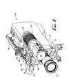
- FIG. 4is a horizontal sectional view schematically showing the support base knuckle 26 , the pivot member 28 and the viewing module 38 with an extension member 60 illustrated as being mountable between the pivot member 28 and the viewing module 38 , as shown by the dot-dash centerline between those components.
- the extension member 60is a rigid tubular member having a front end 62 adapted to fit onto the vertical base 34 of the pivot member 28 and a vertical side surface 64 for slidably engaging the vertical side 36 of the pivot member 28 .
- the extension member 60has a rear end 66 adapted to fit onto the front end 21 of the viewing module 38 when the viewing module 38 is removed from the pivot member 28 .
- the front end 39 of the viewing module 38is joined to the vertical base 34 of the pivot member 28 and the vertical side 41 of the viewing module 38 slidably engages the vertical side 36 of the pivot member 28 .
- the extension member 60may be of any desired length for accommodating the various uses of the viewfinder 20 on camera 10 and, in fact, plural extensions 60 of different lengths may be provided for changing the overall length of the viewfinder 20 to meet different requirements from time-to-time. It should be noted that the addition of the extension member 60 between the pivot member 28 and the viewing module 38 does not modify the image viewed by the cameraman from the eye cup 22 through the eyepiece 48 because the CRT 40 remains in exactly the same position for viewing.
- the extension 60has an electrical plug or connector 63 on the front end 62 and an electrical socket or connector 67 on the rear end 66 .
- the electrical connector 67 on the extension member 60mates with and is releasably connected to an electrical plug or connector 43 on the front end 39 of the viewing module 38 and the electrical socket or connector 63 on the front end 62 of extension member 60 mates with an electrical connector 35 on the vertical base 34 of pivot member 28 .
- the electrical connector 63 on the front of extension member 60is identical to the electrical connection 43 on the front of viewing module 38 and the electrical connector 35 on the pivot member 28 is identical to the electrical connector 67 on the rear end 66 of extension 60 , whereby the viewfinder 20 can be assembled with or without the extension 60 without modifying the electrical connectors between the components.
- An electrical cable 68extends internally of the extension member 60 from one end to the other and connects the electrical connector 63 on the front end 62 to the electrical connector 67 on the rear end 66 .
- the electrical connector 43is provided with a plurality of contact pins 43 a (thirteen of which are shown in this example, although any number may be used) that are spring loaded and in a pattern to match and engage a like plurality of electrical contacts 67 a of electrical connector 67 in a conventional manner.
- a male bayonet connector 70is mounted on the front end 39 of the viewing module 38 and supports the electrical connector 43 .
- a female bayonet lock 72is rotatably mounted on the rear end 66 of the extension member 60 and is provided with a lever 74 and a thumb knob 76 for selectively rotating the bayonet lock 72 .
- the bayonet connector 70has a cylindrical end portion 78 that fits into a cylindrical bore 80 in the end 66 of the extension member 60 .
- the connector 70has three circumferentially extending and spaced flanges 82 that fit through three circumferentially extending and spaced openings 84 in the bayonet lock 72 when inserted in a longitudinal direction, whereby each contact pin 43 a of electrical connector 43 engages electrical contacts 67 a of electrical connector 67 without any rotary movement between the electrical connectors.
- the bayonet lock 72is then rotated by lever 74 and knob 76 to capture the flanges 82 in the circumferential recess 86 on the back of the bayonet lock 72 to thereby lock the viewing module 38 to the extension member 60 .
- a safety lock button 77(see FIG. 2 ) must be depressed to unlock and rotate the bayonet lock 72 .
- a pair of guide pins 88 that are spaced 180° apartare provided on the front end 39 of the viewing module 38 to engage a mating pair of guide bushings 90 installed in the rear end 66 of the extension member 60 to prevent rotation between the viewing module 38 and extension member 60 .
- the viewing module 38 and extension member 60may be readily connected and disconnected, and a very rigid connection is established for supporting one member from the other.
- the complete assembly of the viewfinder 20 with the extension member 60is shown in FIG. 6 .
- the completed connection between the viewing module 38 and the extension member 60is shown in section in FIG. 7 and the identical connection between the front end of extension member 60 and the vertical base 34 of the pivot member 28 is also shown.
- an adjustable extension member 60 ′is shown and mounted between the viewing module 38 and the pivot member 28 in the same manner as the mounting connections used with the extension member 60 of a fixed length.
- the adjustable extension member 60 ′is comprised of an inner tubular member 92 that slidably fits within an outer tubular member 94 on which is provided a clamp 96 for fixedly connecting the two tubular members 92 and 94 in any desired position.
- An electrical cable (not shown) similar to previously described electrical cable 68extends from the front end of tubular member 94 to the rear end of tubular member 92 for connecting the electrical connectors (not shown) on those respective ends, similar to electrical connectors 63 and 67 of extension member 60 .
- the tubular members 92 and 94may be of any desired length for providing the minimum and maximum extensions desired such as, for example, very short tubular members that would allow an adjustment of as little as a three inch length to a five inch length or longer tubular members that would allow an adjustment from an eight inch length to a twelve inch length.
- the portion of the inner tubular member 92 that extends into the outer tubular member 94that is, the overlap of the two members in the maximum extended length must be adequate to provide the structural support between the two sliding tubular members.
- the electrical cablealso must be of an adequate length to accommodate the extension to the maximum length and can be of any conventional type, such as a coiled cable that would resiliently accommodate the extensions and retractions.
- the support base assembly 24includes a rod support base 100 which is attached to the top front portion 18 of the video camera 10 such as by a pair of machine screws 102 .
- the rod support base 100has a pair of parallel sleeves 104 and 106 with bores therethrough for receiving a pair of rods 108 and 110 that extend longitudinally and over the top of the video camera 10 .
- a rod locking mechanism 112is provided on the rod support base 100 and includes a bridge member 114 that extends in a lateral direction over the top of the pair of sleeves 104 and 106 into openings 104 a and 106 a in the sleeves.
- a locking screw with a knob 116is threaded through the rod support base 100 and engages the bridge 114 to selectively raise and lower the bridge 114 to cause the ends of the bridge to selectively release and lock the rods 108 and 110 in the sleeves 104 and 106 , respectively, thereby allowing fore and aft adjustment of the rods 108 and 110 for a substantial distance.
- the front of the rods 108 and 110are connected to a dovetail slot member 118 that extends longitudinally and supports a mating dovetail slot member 120 on the knuckle 26 (see FIG. 2 ) to allow lateral adjustment of the viewfinder 20 relative to the camera 10 for a substantial distance by reason of the substantial lengths of the dovetail members 118 and 120 .
- a locking screw 122is provided on dovetail member 120 to selectively lock the dovetail members 118 and 120 together at any desired lateral position.
- An electrical cable 124 with a plug 126 for connecting to the side of the camera 10 (see FIG. 1 )extends from the end of the knuckle 26 .
- the wires (not shown) from cable 124extend through the knuckle 26 , the locking mechanism 30 and pivot member 28 to the electrical connector 35 in the base of the pivot member 28 to thereby connect the electronics from the camera 10 to the CRT control means 42 in the viewing module 38 .
- the viewfinder 20 of this inventionis mounted on the camera 10 by the support base assembly 24 and is longitudinally adjustable for the full length of the pair of rods 108 , 110 and laterally adjustable for the full length of the pair of dovetail members 118 , 120 for selectively locating the viewfinder 20 in the most desirable position for the cameraman and/or the type of use that is being made of the video camera from time-to-time. Still further, by loosening and locking the pivot locking mechanism 30 , the angular position of the viewfinder 20 relative to the camera 10 may be adjusted. Further, the longitudinal length of the viewfinder 20 may be changed for the particular use by inserting an extension member 60 of a desired length or by inserting a telescoping extension member 60 ′ and appropriately adjusting its length.
- a universally adjustable viewfinder 20is provided that can comfortably accommodate any proposed use of the video camera 10 and yet the image displayed on the CRT 40 that is viewed from the eye cup 22 through the eyepiece 48 is not changed by any of the adjustments or extension members, although the focus on the CRT 40 is adjustable over a wide range to accommodate the eye sight of the cameraman. While the viewfinder 20 of this invention has been described in detail and in connection with its use on a specific video camera for a complete disclosure of a preferred embodiment of the invention, it will readily appear to those skilled in the art that numerous variations and modifications may be employed without departing from the scope of this invention as defined by the accompanying claims.
Landscapes
- Engineering & Computer Science (AREA)
- Multimedia (AREA)
- Signal Processing (AREA)
- Viewfinders (AREA)
- Studio Devices (AREA)
Abstract
Description
Claims (33)
Priority Applications (5)
| Application Number | Priority Date | Filing Date | Title |
|---|---|---|---|
| US09/838,060US6927797B2 (en) | 2001-04-19 | 2001-04-19 | Viewfinder for high definition video camera |
| AU29265/02AAU783936B2 (en) | 2001-04-19 | 2002-03-28 | Viewfinder for high definition video camera |
| CA002380135ACA2380135C (en) | 2001-04-19 | 2002-04-03 | Viewfinder for high definition video camera |
| EP02007673AEP1251691A3 (en) | 2001-04-19 | 2002-04-04 | Viewfinder for high definition video camera |
| JP2002112160AJP4047618B2 (en) | 2001-04-19 | 2002-04-15 | Viewfinder for high-definition video camera |
Applications Claiming Priority (1)
| Application Number | Priority Date | Filing Date | Title |
|---|---|---|---|
| US09/838,060US6927797B2 (en) | 2001-04-19 | 2001-04-19 | Viewfinder for high definition video camera |
Publications (2)
| Publication Number | Publication Date |
|---|---|
| US20020154237A1 US20020154237A1 (en) | 2002-10-24 |
| US6927797B2true US6927797B2 (en) | 2005-08-09 |
Family
ID=25276141
Family Applications (1)
| Application Number | Title | Priority Date | Filing Date |
|---|---|---|---|
| US09/838,060Expired - LifetimeUS6927797B2 (en) | 2001-04-19 | 2001-04-19 | Viewfinder for high definition video camera |
Country Status (5)
| Country | Link |
|---|---|
| US (1) | US6927797B2 (en) |
| EP (1) | EP1251691A3 (en) |
| JP (1) | JP4047618B2 (en) |
| AU (1) | AU783936B2 (en) |
| CA (1) | CA2380135C (en) |
Cited By (1)
| Publication number | Priority date | Publication date | Assignee | Title |
|---|---|---|---|---|
| US20040160523A1 (en)* | 2002-10-25 | 2004-08-19 | Sony Corporation | Video camera |
Families Citing this family (8)
| Publication number | Priority date | Publication date | Assignee | Title |
|---|---|---|---|---|
| EP3103422A1 (en)* | 2003-03-14 | 2016-12-14 | Intersect ENT, Inc. | Sinus delivery of sustained release therapeutics |
| JP4380475B2 (en)* | 2003-10-02 | 2009-12-09 | ソニー株式会社 | Imaging device |
| JP2005141008A (en)* | 2003-11-06 | 2005-06-02 | Pentax Corp | Telescope, telescope body and electronic viewfinder device |
| KR20080091674A (en)* | 2007-04-09 | 2008-10-14 | 삼성전자주식회사 | Electronic device and control method |
| JP2011223305A (en)* | 2010-04-09 | 2011-11-04 | Sony Corp | Viewfinder |
| JP5972622B2 (en)* | 2012-03-23 | 2016-08-17 | シチズンファインデバイス株式会社 | Electronic viewfinder using a reflective liquid crystal display |
| CN113759634B (en)* | 2016-01-07 | 2024-07-12 | Lg伊诺特有限公司 | Lens driving device, camera module and optical equipment |
| DE102016106953A1 (en) | 2016-04-14 | 2017-10-19 | Arnold & Richter Cine Technik Gmbh & Co. Betriebs Kg | camera viewfinder |
Citations (24)
| Publication number | Priority date | Publication date | Assignee | Title |
|---|---|---|---|---|
| US3845238A (en)* | 1972-04-07 | 1974-10-29 | Bosch Fernsehanlagen | Portable television camera with audio communication |
| US4017168A (en)* | 1974-09-16 | 1977-04-12 | Brown Garrett W | Equipment for use with hand held motion picture cameras |
| US4550343A (en)* | 1983-07-15 | 1985-10-29 | Olympus Optical Co., Ltd. | Video camera apparatus |
| US4557572A (en)* | 1978-06-12 | 1985-12-10 | Willi Schickedanz | Camera |
| JPS6159974A (en)* | 1984-08-31 | 1986-03-27 | Canon Inc | Electronic camera and lens barrel |
| DE3525526C1 (en)* | 1985-07-17 | 1987-02-26 | Peter Denz | Motion-picture film camera with viewing magnifier extension |
| US4682240A (en)* | 1985-06-07 | 1987-07-21 | Robert Bosch Gmbh | Interlocked television camera and electronic viewfinder combination |
| JPS6423239A (en)* | 1987-07-17 | 1989-01-25 | Matsushita Electric Industrial Co Ltd | View finder device for camera |
| JPH0250679A (en)* | 1988-08-12 | 1990-02-20 | Matsushita Electric Ind Co Ltd | Camera-integrated magnetic recording and reproducing device |
| US4959729A (en)* | 1987-11-25 | 1990-09-25 | Fuji Photo Film Co., Ltd. | Video camera having rotatable viewfinder |
| US4963987A (en)* | 1987-11-06 | 1990-10-16 | Canon Kabushiki Kaisha | Video camera apparatus with grip axis and viewfinder optical axis in parallel relation |
| JPH02262772A (en)* | 1989-04-03 | 1990-10-25 | Mitsubishi Electric Corp | Camera integrated VTR |
| JPH05145808A (en)* | 1991-11-18 | 1993-06-11 | Sony Corp | View finder mounting device for camera |
| JPH0622184A (en)* | 1992-07-03 | 1994-01-28 | Hitachi Ltd | Electronic camera viewfinder moving mechanism |
| US5300976A (en)* | 1992-04-17 | 1994-04-05 | Goldstar Co., Ltd. | Movie camera system having view finding and projecting operations |
| US5321456A (en)* | 1992-04-21 | 1994-06-14 | Daewoo Electronics Co., Ltd. | Detachable view finder for video camera |
| DE4302173A1 (en)* | 1993-01-22 | 1994-07-28 | Arnold & Richter Kg | Reflex cine camera with adaptor for video image transmission |
| JPH06233160A (en)* | 1993-02-02 | 1994-08-19 | Mitsubishi Electric Corp | Camera integrated VTR |
| US5696555A (en)* | 1989-03-30 | 1997-12-09 | Canon Kabushiki Kaisha | Image input apparatus having a detachably connected camera body and monitor or control unit |
| US5767906A (en)* | 1995-04-12 | 1998-06-16 | Matsushita Electric Industrial Co., Ltd. | Viewfinder mounting for video camera |
| US5893649A (en)* | 1990-05-25 | 1999-04-13 | Sony Corporation | Camera-mounted VTR |
| US5920426A (en)* | 1997-11-20 | 1999-07-06 | Panavision, Inc. | Telescopic viewfinder optical system |
| US6480681B1 (en)* | 1999-08-26 | 2002-11-12 | Panavision, Inc. | Adjustable viewfinder optical system for shoulder-supported cameras |
| US6778775B1 (en)* | 1999-04-07 | 2004-08-17 | Thomson Licensing S.A. | Video camera with flat screen viewfinder |
Family Cites Families (4)
| Publication number | Priority date | Publication date | Assignee | Title |
|---|---|---|---|---|
| JPS56147436U (en)* | 1980-04-05 | 1981-11-06 | ||
| JPS57171324A (en)* | 1981-04-14 | 1982-10-21 | Victor Co Of Japan Ltd | Shifting mechanism of viewfinder |
| JPH05110911A (en)* | 1991-10-15 | 1993-04-30 | Canon Inc | Camera integrated VTR |
| JPH05292363A (en)* | 1992-04-16 | 1993-11-05 | Hitachi Ltd | Structure for view finder |
- 2001
- 2001-04-19USUS09/838,060patent/US6927797B2/ennot_activeExpired - Lifetime
- 2002
- 2002-03-28AUAU29265/02Apatent/AU783936B2/ennot_activeExpired
- 2002-04-03CACA002380135Apatent/CA2380135C/ennot_activeExpired - Fee Related
- 2002-04-04EPEP02007673Apatent/EP1251691A3/ennot_activeWithdrawn
- 2002-04-15JPJP2002112160Apatent/JP4047618B2/ennot_activeExpired - Lifetime
Patent Citations (24)
| Publication number | Priority date | Publication date | Assignee | Title |
|---|---|---|---|---|
| US3845238A (en)* | 1972-04-07 | 1974-10-29 | Bosch Fernsehanlagen | Portable television camera with audio communication |
| US4017168A (en)* | 1974-09-16 | 1977-04-12 | Brown Garrett W | Equipment for use with hand held motion picture cameras |
| US4557572A (en)* | 1978-06-12 | 1985-12-10 | Willi Schickedanz | Camera |
| US4550343A (en)* | 1983-07-15 | 1985-10-29 | Olympus Optical Co., Ltd. | Video camera apparatus |
| JPS6159974A (en)* | 1984-08-31 | 1986-03-27 | Canon Inc | Electronic camera and lens barrel |
| US4682240A (en)* | 1985-06-07 | 1987-07-21 | Robert Bosch Gmbh | Interlocked television camera and electronic viewfinder combination |
| DE3525526C1 (en)* | 1985-07-17 | 1987-02-26 | Peter Denz | Motion-picture film camera with viewing magnifier extension |
| JPS6423239A (en)* | 1987-07-17 | 1989-01-25 | Matsushita Electric Industrial Co Ltd | View finder device for camera |
| US4963987A (en)* | 1987-11-06 | 1990-10-16 | Canon Kabushiki Kaisha | Video camera apparatus with grip axis and viewfinder optical axis in parallel relation |
| US4959729A (en)* | 1987-11-25 | 1990-09-25 | Fuji Photo Film Co., Ltd. | Video camera having rotatable viewfinder |
| JPH0250679A (en)* | 1988-08-12 | 1990-02-20 | Matsushita Electric Ind Co Ltd | Camera-integrated magnetic recording and reproducing device |
| US5696555A (en)* | 1989-03-30 | 1997-12-09 | Canon Kabushiki Kaisha | Image input apparatus having a detachably connected camera body and monitor or control unit |
| JPH02262772A (en)* | 1989-04-03 | 1990-10-25 | Mitsubishi Electric Corp | Camera integrated VTR |
| US5893649A (en)* | 1990-05-25 | 1999-04-13 | Sony Corporation | Camera-mounted VTR |
| JPH05145808A (en)* | 1991-11-18 | 1993-06-11 | Sony Corp | View finder mounting device for camera |
| US5300976A (en)* | 1992-04-17 | 1994-04-05 | Goldstar Co., Ltd. | Movie camera system having view finding and projecting operations |
| US5321456A (en)* | 1992-04-21 | 1994-06-14 | Daewoo Electronics Co., Ltd. | Detachable view finder for video camera |
| JPH0622184A (en)* | 1992-07-03 | 1994-01-28 | Hitachi Ltd | Electronic camera viewfinder moving mechanism |
| DE4302173A1 (en)* | 1993-01-22 | 1994-07-28 | Arnold & Richter Kg | Reflex cine camera with adaptor for video image transmission |
| JPH06233160A (en)* | 1993-02-02 | 1994-08-19 | Mitsubishi Electric Corp | Camera integrated VTR |
| US5767906A (en)* | 1995-04-12 | 1998-06-16 | Matsushita Electric Industrial Co., Ltd. | Viewfinder mounting for video camera |
| US5920426A (en)* | 1997-11-20 | 1999-07-06 | Panavision, Inc. | Telescopic viewfinder optical system |
| US6778775B1 (en)* | 1999-04-07 | 2004-08-17 | Thomson Licensing S.A. | Video camera with flat screen viewfinder |
| US6480681B1 (en)* | 1999-08-26 | 2002-11-12 | Panavision, Inc. | Adjustable viewfinder optical system for shoulder-supported cameras |
Non-Patent Citations (1)
| Title |
|---|
| Literature from OpTex entitled "Electronic Extension Viewfinder For Sony ENG Cameras", dated Nov. 1990. |
Cited By (1)
| Publication number | Priority date | Publication date | Assignee | Title |
|---|---|---|---|---|
| US20040160523A1 (en)* | 2002-10-25 | 2004-08-19 | Sony Corporation | Video camera |
Also Published As
| Publication number | Publication date |
|---|---|
| CA2380135A1 (en) | 2002-10-19 |
| JP4047618B2 (en) | 2008-02-13 |
| CA2380135C (en) | 2009-02-10 |
| EP1251691A3 (en) | 2006-05-10 |
| EP1251691A2 (en) | 2002-10-23 |
| JP2002344780A (en) | 2002-11-29 |
| AU783936B2 (en) | 2006-01-05 |
| AU2926502A (en) | 2002-10-24 |
| US20020154237A1 (en) | 2002-10-24 |
Similar Documents
| Publication | Publication Date | Title |
|---|---|---|
| JP4204436B2 (en) | Shoulder-mounted camera support device for fixing camera or video camera | |
| EP1692862B1 (en) | Positioning accessory for camera-equipped wireless terminals | |
| US6318912B1 (en) | Adapter having a tilt and shift mechanism | |
| US6927797B2 (en) | Viewfinder for high definition video camera | |
| JP4479818B2 (en) | Viewfinder and imaging device | |
| JPH02211779A (en) | Equipment support,handle for this equipment support,and stabilized image recording method and stabilized image recorded by this recording method | |
| US4930883A (en) | Photovisual star diagonal | |
| US7318678B2 (en) | Self locking ergonomic support assembly for optical devices | |
| US6667836B2 (en) | High performance viewfinder eyepiece with a large diopter focus range | |
| US4771302A (en) | Camera with orientable taking lens and a device for attaching a flash unit | |
| US9354492B2 (en) | Camera mount assembly, methods of production and uses thereof | |
| US4409619A (en) | Television camera with an electronic view finder | |
| US20030202118A1 (en) | Portable apparatus | |
| WO2020000679A1 (en) | Parameter adjustment apparatus and pan-tilt device having same | |
| US20050253961A1 (en) | Pivot shaft mechanism, and a pivot shaft mechanism of a camera for pivoting a rotatable grip on a camera body | |
| CN114785922A (en) | Image pickup apparatus | |
| JPH06160957A (en) | Fixture supporting tool for camera and optional lens | |
| JP2004147232A (en) | View finder and video camera | |
| JP3453536B2 (en) | Conversion lens mounting mechanism | |
| US20220321751A1 (en) | Camera viewfinder system | |
| JPH1198388A (en) | Low angle grip mounting mechanism for eng camera | |
| CN222939327U (en) | A display optical machine and AR glasses | |
| US20230345103A1 (en) | Adjustable digital cinema camera optical viewfinder | |
| JPH0411421Y2 (en) | ||
| JP2020197579A (en) | Adapter device and image capturing device |
Legal Events
| Date | Code | Title | Description |
|---|---|---|---|
| AS | Assignment | Owner name:PANAVISION, INC., CALIFORNIA Free format text:ASSIGNMENT OF ASSIGNORS INTEREST;ASSIGNOR:GELBARD, RICHARD;REEL/FRAME:011734/0687 Effective date:20010413 | |
| AS | Assignment | Owner name:JPMORGAN CHASE BANK, AS ADMINISTRATIVE AGENT, TEXA Free format text:SECURITY INTEREST;ASSIGNOR:PANAVISION INC. (DE CORPORATION);REEL/FRAME:012983/0510 Effective date:20020507 | |
| AS | Assignment | Owner name:WILMINGTON TRUST, AS COLLATERAL TRUSTEE, DELAWARE Free format text:COLLATERAL AGREEMENT;ASSIGNORS:PANAVISION INC.;PANAPAGE ONE LLC;PANAPAGE TWO LLC;AND OTHERS;REEL/FRAME:014294/0009 Effective date:20040116 | |
| STCF | Information on status: patent grant | Free format text:PATENTED CASE | |
| AS | Assignment | Owner name:PANAPAGE INTERNATIONAL, L.P., CALIFORNIA Free format text:RELEASE BY SECURED PARTY;ASSIGNOR:WILMINGTON TRUST COMPANY;REEL/FRAME:017388/0409 Effective date:20060329 Owner name:PANAPAGE ONE LLC, CALIFORNIA Free format text:RELEASE BY SECURED PARTY;ASSIGNOR:WILMINGTON TRUST COMPANY;REEL/FRAME:017388/0409 Effective date:20060329 Owner name:PANAPAGE CO. LLC, CALIFORNIA Free format text:RELEASE BY SECURED PARTY;ASSIGNOR:WILMINGTON TRUST COMPANY;REEL/FRAME:017388/0409 Effective date:20060329 Owner name:PANAPAGE TWO LLC, CALIFORNIA Free format text:RELEASE BY SECURED PARTY;ASSIGNOR:WILMINGTON TRUST COMPANY;REEL/FRAME:017388/0409 Effective date:20060329 Owner name:PANAVISION INC., CALIFORNIA Free format text:RELEASE BY SECURED PARTY;ASSIGNOR:WILMINGTON TRUST COMPANY;REEL/FRAME:017388/0409 Effective date:20060329 Owner name:PANAVISION REMOTE SYSTEMS, LLC, CALIFORNIA Free format text:RELEASE BY SECURED PARTY;ASSIGNOR:WILMINGTON TRUST COMPANY;REEL/FRAME:017388/0409 Effective date:20060329 Owner name:PANAVISION U.K. HOLDINGS, INC., CALIFORNIA Free format text:RELEASE BY SECURED PARTY;ASSIGNOR:WILMINGTON TRUST COMPANY;REEL/FRAME:017388/0409 Effective date:20060329 Owner name:LAS PALMAS PRODUCTIONS, INC., CALIFORNIA Free format text:RELEASE BY SECURED PARTY;ASSIGNOR:WILMINGTON TRUST COMPANY;REEL/FRAME:017388/0409 Effective date:20060329 | |
| AS | Assignment | Owner name:PANAVISION INC., CALIFORNIA Free format text:RELEASE BY SECURED PARTY;ASSIGNOR:JPMORGAN CHASE BANK, N.A.;REEL/FRAME:017411/0770 Effective date:20060329 | |
| AS | Assignment | Owner name:CREDIT SUISSE, AS FIRST LIEN COLLATERAL AGENT, NEW Free format text:SECURITY AGREEMENT;ASSIGNORS:PANAVISION INC.;PANAVISION INTERNATIONAL, L.P.;REEL/FRAME:017468/0678 Effective date:20060330 | |
| AS | Assignment | Owner name:CREDIT SUISSE, AS SECOND LIEN COLLATERAL AGENT, NE Free format text:SECURITY AGREEMENT;ASSIGNORS:PANAVISION INC.;PANAVISION INTERNATIONAL, L.P.;REEL/FRAME:017480/0803 Effective date:20060330 | |
| FPAY | Fee payment | Year of fee payment:4 | |
| FPAY | Fee payment | Year of fee payment:8 | |
| AS | Assignment | Owner name:BANK OF AMERICA, N.A., AS AGENT AND U.S. LENDER, C Free format text:SECURITY INTEREST;ASSIGNORS:PANAVISION INC.;PANAVISION INTERNATIONAL, L.P.;LIGHT IRON DIGITAL, LLC;AND OTHERS;REEL/FRAME:037693/0662 Effective date:20160205 | |
| AS | Assignment | Owner name:PANAVISION INTERNATIONAL, L.P., CALIFORNIA Free format text:RELEASE BY SECURED PARTY;ASSIGNOR:CREDIT SUISSE, AS SECOND LIEN COLLATERAL AGENT;REEL/FRAME:037846/0116 Effective date:20160225 Owner name:PANAVISION INC., CALIFORNIA Free format text:RELEASE BY SECURED PARTY;ASSIGNOR:CREDIT SUISSE, AS SECOND LIEN COLLATERAL AGENT;REEL/FRAME:037846/0116 Effective date:20160225 | |
| FPAY | Fee payment | Year of fee payment:12 | |
| AS | Assignment | Owner name:ALTER DOMUS (US) LLC, ILLINOIS Free format text:SECURITY INTEREST;ASSIGNORS:PANAVISION INC.;PANAVISION INTERNATIONAL, L.P.;LIGHT IRON DIGITAL, LLC;AND OTHERS;REEL/FRAME:054285/0199 Effective date:20201029 | |
| AS | Assignment | Owner name:COURTLAND CAPITAL MARKET SERVICES LLC, ILLINOIS Free format text:ASSIGNMENT OF ASSIGNORS INTEREST;ASSIGNOR:CREDIT SUISSE AG, CAYMAN ISLANDS BRANCH AS RETIRED AGENT;REEL/FRAME:060932/0054 Effective date:20220829 | |
| AS | Assignment | Owner name:PANAVISION INTERNATIONAL, L.P., CALIFORNIA Free format text:RELEASE BY SECURED PARTY;ASSIGNOR:CORTLAND CAPITAL MARKET SERVICES LLC;REEL/FRAME:060951/0548 Effective date:20220829 Owner name:PANAVISION INC., CALIFORNIA Free format text:RELEASE BY SECURED PARTY;ASSIGNOR:CORTLAND CAPITAL MARKET SERVICES LLC;REEL/FRAME:060951/0548 Effective date:20220829 | |
| AS | Assignment | Owner name:BANK OF AMERICA, N.A., AS AGENT, CALIFORNIA Free format text:SECURITY INTEREST;ASSIGNOR:PANAVISION INTERNATIONAL, L.P.;REEL/FRAME:062114/0459 Effective date:20221209 | |
| AS | Assignment | Owner name:PANALUX LIMITED, CALIFORNIA Free format text:RELEASE BY SECURED PARTY;ASSIGNOR:BANK OF AMERICA, N.A.;REEL/FRAME:071043/0144 Effective date:20250502 Owner name:PANAVISION EUROPE LIMITED, CALIFORNIA Free format text:RELEASE BY SECURED PARTY;ASSIGNOR:BANK OF AMERICA, N.A.;REEL/FRAME:071043/0144 Effective date:20250502 Owner name:SEAWAY MEDIA CORPORATION, CALIFORNIA Free format text:RELEASE BY SECURED PARTY;ASSIGNOR:BANK OF AMERICA, N.A.;REEL/FRAME:071043/0144 Effective date:20250502 Owner name:PANAVISION U.K. HOLDINGS, INC., CALIFORNIA Free format text:RELEASE BY SECURED PARTY;ASSIGNOR:BANK OF AMERICA, N.A.;REEL/FRAME:071043/0144 Effective date:20250502 Owner name:PANAVISION IMAGING, LLC, CALIFORNIA Free format text:RELEASE BY SECURED PARTY;ASSIGNOR:BANK OF AMERICA, N.A.;REEL/FRAME:071043/0144 Effective date:20250502 Owner name:LIGHT IRON NY, LLC, CALIFORNIA Free format text:RELEASE BY SECURED PARTY;ASSIGNOR:BANK OF AMERICA, N.A.;REEL/FRAME:071043/0144 Effective date:20250502 Owner name:PANAVISION REMOTE SYSTEMS LLC, CALIFORNIA Free format text:RELEASE BY SECURED PARTY;ASSIGNOR:BANK OF AMERICA, N.A.;REEL/FRAME:071043/0144 Effective date:20250502 Owner name:PANAVISION FEDERAL SYSTEMS, LLC, CALIFORNIA Free format text:RELEASE BY SECURED PARTY;ASSIGNOR:BANK OF AMERICA, N.A.;REEL/FRAME:071043/0144 Effective date:20250502 Owner name:PANY RENTAL LLC, CALIFORNIA Free format text:RELEASE BY SECURED PARTY;ASSIGNOR:BANK OF AMERICA, N.A.;REEL/FRAME:071043/0144 Effective date:20250502 Owner name:LIGHT IRON DIGITAL, LLC, CALIFORNIA Free format text:RELEASE BY SECURED PARTY;ASSIGNOR:BANK OF AMERICA, N.A.;REEL/FRAME:071043/0144 Effective date:20250502 Owner name:PANAVISION INTERNATIONAL, L.P., CALIFORNIA Free format text:RELEASE BY SECURED PARTY;ASSIGNOR:BANK OF AMERICA, N.A.;REEL/FRAME:071043/0144 Effective date:20250502 Owner name:PANAVISION GP LLC, CALIFORNIA Free format text:RELEASE BY SECURED PARTY;ASSIGNOR:BANK OF AMERICA, N.A.;REEL/FRAME:071043/0144 Effective date:20250502 Owner name:PANAVISION INC., CALIFORNIA Free format text:RELEASE BY SECURED PARTY;ASSIGNOR:BANK OF AMERICA, N.A.;REEL/FRAME:071043/0144 Effective date:20250502 |