US6927736B1 - System and method for integrating antennas into a vehicle rear-deck spoiler - Google Patents
System and method for integrating antennas into a vehicle rear-deck spoilerDownload PDFInfo
- Publication number
- US6927736B1 US6927736B1US10/440,449US44044903AUS6927736B1US 6927736 B1US6927736 B1US 6927736B1US 44044903 AUS44044903 AUS 44044903AUS 6927736 B1US6927736 B1US 6927736B1
- Authority
- US
- United States
- Prior art keywords
- antenna
- monopole
- riser
- spoiler
- monopole antenna
- Prior art date
- Legal status (The legal status is an assumption and is not a legal conclusion. Google has not performed a legal analysis and makes no representation as to the accuracy of the status listed.)
- Expired - Lifetime, expires
Links
- 238000000034methodMethods0.000titledescription6
- 230000005404monopoleEffects0.000claimsabstractdescription86
- 238000004891communicationMethods0.000abstractdescription3
- 238000009434installationMethods0.000abstractdescription2
- 239000004020conductorSubstances0.000description14
- 230000010354integrationEffects0.000description6
- 230000008901benefitEffects0.000description4
- 230000000694effectsEffects0.000description4
- 239000002184metalSubstances0.000description4
- 230000003071parasitic effectEffects0.000description4
- 230000005540biological transmissionEffects0.000description2
- 238000005259measurementMethods0.000description2
- 239000004677NylonSubstances0.000description1
- 230000001413cellular effectEffects0.000description1
- 238000010276constructionMethods0.000description1
- 238000009413insulationMethods0.000description1
- 239000012212insulatorSubstances0.000description1
- 230000003993interactionEffects0.000description1
- 238000012986modificationMethods0.000description1
- 230000004048modificationEffects0.000description1
- 229920001778nylonPolymers0.000description1
- 230000005855radiationEffects0.000description1
- 238000012360testing methodMethods0.000description1
Images


Classifications
- H—ELECTRICITY
- H01—ELECTRIC ELEMENTS
- H01Q—ANTENNAS, i.e. RADIO AERIALS
- H01Q1/00—Details of, or arrangements associated with, antennas
- H01Q1/27—Adaptation for use in or on movable bodies
- H01Q1/32—Adaptation for use in or on road or rail vehicles
- H01Q1/325—Adaptation for use in or on road or rail vehicles characterised by the location of the antenna on the vehicle
- H01Q1/3275—Adaptation for use in or on road or rail vehicles characterised by the location of the antenna on the vehicle mounted on a horizontal surface of the vehicle, e.g. on roof, hood, trunk
Definitions
- the present inventionrelates to antennas installed on an automobile or other vehicle.
- the only antenna found on an automobile or other vehiclewas likely to be a monopole whip antenna for an AM/FM radio.
- a vehiclesuch an automobile, boat, an the like, is likely to have several antennas for various devices, such as, for example, an AM/FM radio, a cellular telephone, a satellite radio, a GPS receiver, etc.
- police, emergency vehicles, and aircrafthave even more antennas for various radio communication and/or data systems.
- other sensorssuch as electro-optic sensors, cameras, etc. are also becoming more common on vehicles. These antennas and other sensors are often considered to be unsightly.
- sensors that are not integrated into the vehicleare more likely to be damaged by accidents or vandalism, and can reduce gas mileage by creating aerodynamic drag.
- sensorssuch as antennas are integrated into an automotive spoiler-type device to support the transmission and reception of information.
- sensorscan include, for example, transmit antennas, receive antennas, video cameras, Infrared (IR) sensors, Electro-Optic (EO) sensors, air sensors, etc.
- IRInfrared
- EOElectro-Optic
- the information transmitted and receivedinclude voice, data, navigation, and other communications functions, including, but not limited to, two-way radios, GPS, wireless Internet applications, etc.
- the spoiler antenna installationsare lower in profile and more compact than conventional vehicle antennas.
- sensors in a spoilerwhich is installed as a unit, has the additional benefits of concealment (the presence of equipment in the vehicle is not revealed by visible sensors and/or antennas), protection of the sensors from damage, (e.g., car wash damage, vandalism, etc.) robustness, and reduced life-cycle costs.
- four antennas and a brake lightare provided in a spoiler.
- three antennascover three transmit/receive frequency bands, namely 150–160 MHz, 423–469 MHz, and 806–869 MHz.
- the fourth antennacovers the GPS receive bands. These frequency bands represent so-called instantaneous bandwidths of the antennas (where tuning is not needed to achieve a desired transmit/receive performance over the stated bands). These particular transmit/receive frequency bands are currently being used by police, fire and various business radio services.
- the 150–160 MHz banddemonstrates a relatively long-wavelength case ( ⁇ >6 feet).
- one or more of the spoiler antennashandle Continuous Wave (CW) transmit power levels of up to approximately 100 Watts.
- CWContinuous Wave
- the spoiler antennasare configured as monopole and top-loaded monopole antennas.
- other antennassuch as, for example, GPS antennas, satellite radio antennas, etc. are integrated into the spoiler.
- FIG. 1shows a suite of antennas integrated into an automobile spoiler-type structure to provide relatively moderate bandwidth coverage.
- FIG. 2shows a suite of antennas integrated into an automobile spoiler-type structure to provide relatively wide bandwidth coverage.
- FIG. 3shows power reception as a function of aspect angle at 155 MHz for a spoiler-mounted antenna and for a standard monopole whip antenna.
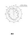
- FIG. 4shows power reception as a function of aspect angle at 446 MHz for a spoiler-mounted antenna and for a standard monopole whip antenna.
- FIG. 5shows power reception as a function of aspect angle at 837 MHz for a spoiler-mounted antenna and for a standard monopole whip antenna.
- FIG. 6shows power reception as a function of aspect angle at 155 MHz for a spoiler-mounted antenna with and without a third brake light in the spoiler.
- FIG. 7shows a coax connection for the integrated antenna.
- FIG. 8shows one embodiment of a top-loaded antenna for integration in a spoiler.
- FIG. 9shows integration of monopoles and top-loaded monopoles into an automobile spoiler.
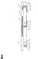
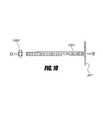
- FIG. 10shows construction of a monopole antenna for integration into an automobile spoiler.
- FIG. 11shows integration of a patch-type antenna, including a coaxial signal path, into an automobile spoiler.
- FIG. 12shows integration of a cavity-type antenna, including a coaxial signal path, into an automobile spoiler.
- FIG. 13shows integration of a coaxial signal path for the antennas of FIG. 11 or 12 into a monopole antenna.
- FIG. 1shows one embodiment of a system 100 having an antenna suite integrated into a spoiler-type structure on an automobile or other vehicle.
- the system 100includes a spoiler 101 , a low-band antenna 102 , a medium-band antenna 104 , and a high-band antenna 102 .
- the antennas 102 – 104are monopole-type antennas.
- the low-band antenna 102 and the medium-band antenna 104are top-loaded monopoles.
- the low-band antenna 103operates in a band from 150–160 MHz.
- the medium-band antenna 104operates in a band from 423–469 MHz.
- the high-band antenna 103operates in a band from 806–869 MHz.
- the low-band antenna 103is located between the medium-band antenna 104 and the high-band antenna 102 .
- the spoiler 101includes three risers (left, center, and right) that connect the spoiler 101 to the vehicle.
- the vertical portion of the monopole-type antennas used for the antennas 102 – 104are located in the three risers.
- a horizontal-type antenna 105is also integrated into the spoiler 101 .
- the horizontal-type antenna 105can be an annular ring antenna, patch antenna, microstrip antenna, stripline antenna etc.
- the horizontal-type antenna 105is used for receiving satellite signals for systems such as, for example, XM radio, Global Positioning System (GPS) navigation, etc.
- GPSGlobal Positioning System
- the spoiler 101also incorporates a brake light 110 .
- the brake light 110is usually a “third brake light” that is provided in addition to the typical left and right brake lights found on vehicles.
- the type of light used for the brake light 110 , and the power connections to the third brake light 110are configured to reduce effects that the power lines might otherwise have on antenna performance (e.g., antenna pattern or impedance).
- the brake light 110uses a plurality (e.g. sixty) of high-intensity light emitting diodes (LEDs) powered by twelve volts of direct current.
- the direct current voltageis applied to the LED array through two parallel #18 AWG wires. These wires are molded into a common insulation package that electrically insulates them from one another and their surroundings.
- the brake light power leadsare routed through the spoiler along a tapered path nearly parallel to the vertical portion of the low-band antenna 103 . The average spacing along this taper is approximately 0.75′′. In this case, the power lead contributes to the ease of impedance matching with minimal effects upon the monopole radiation pattern by acting as parasitic elements.
- FIG. 2shows a system 200 that is similar to the system 100 and includes the spoiler 101 , the horizontal-type antenna 105 and, optionally, the brake light 110 .
- a low-band antenna 203operates in a frequency band of 150–250 MHz
- a medium-band antennaoperates in a frequency band of 250–500 MHz
- a high-band antennaoperates in a frequency band of 500–2500 MHz.
- the system 200provides bandwidth coverage from 150 MHz to 2.5 GHz.
- Radio Frequency (RF) chokesare used to reduce interactions between the antennas 202 – 203 .
- the upper frequency shown in FIG. 2 (2500 MHz)is not a limitation and higher frequencies can be accommodated by using additional horizontal-type antennas similar to the horizontal-type antenna 105 .
- a top portion of the low-band antenna 203acts as a ground plane for the horizontal-type antennas such as the horizontal-type antenna 105 .
- signal linese.g., coaxial cables
- the horizontal-type antennassuch as the horizontal-type antenna 105 are routed through the vertical portion of the low-band antenna 203 .
- FIGS. 3–5show pattern measurements on embodiments of the spoiler mounted antennas shown in FIGS. 1 and 2 . Pattern measurements were performed for a spoiler (with integrated antennas) mounted on the vehicle. The spoiler antenna patterns were compared to conventional whip antenna patterns. In one embodiment, the conventional whip antennas used for comparison were mounted near the center of the trunk lid.
- FIG. 3shows 155 MHz data.
- FIG. 4shows 446 MHz data.
- FIG. 5shows 837 MHz data.
- the amplitude scaleis relative dB, not dBi gain.
- the spoiler antennashave better pattern coverage than the corresponding whip antenna, especially for aspects where the whip patterns are marginal.
- the data in FIG. 6shows the measured effect of the third brake light power leads on the pattern of the low-band antenna 103 with and without power leads.
- the power leadshas relatively little effect on the antenna pattern.
- FIG. 7shows one embodiment of an antenna connection to a coaxial cable.
- the coaxial cablelocated inside the trunk, has a center conductor 701 and a shield 702 .
- a metal tab 703is provided to the shield and a metal tab 704 is provided to the center conductor.
- the metal tab 703 provided to the shieldcan be attached to a suitable ground plane, such as, for example, a trunk lid.
- the metal tab 704 provided to the center conductorcan be attached to a monopole-type antenna, such as, for example the antennas 102 – 104 or 202 – 204 .
- An alternate technique, usually desirable for higher frequencies,is to connect the antenna lead and ground to a conventional bulkhead connector.
- the configuration shown in FIG. 7has the advantage of being relatively low-cost and relatively low-profile.
- FIG. 8shows one embodiment of a top load 801 for a monopole such as the low-band antennas 103 and 203 .
- Top loadingincreases the effective length of the monopole and therefore allows the monopole to operate a lower frequency with a relatively smaller vertical height than an unloaded monopole.
- the top loadis constructed from a relatively thin sheet of conducting material and is suitable for use as a ground plane for other antennas.
- the top load 801is attached at or near the top of a monopole antenna, as shown, for example, in FIGS. 1 and 2 .
- FIG. 9shows three antenna locations for monopole-type antennas in the spoiler 101 .
- a first monopole 911is placed inside a left-hand riser 901 of the spoiler 101 .
- a base of the first monopole 911 antennais provided at or electrically near the rear deck surface to which the spoiler is attached (e.g., to the trunk of the vehicle).
- the monopole 911is provided to the center conductor of the coaxial cable according to the configuration shown in FIG. 7 .
- the monopole 911extends at least partially up into the left-hand riser 901 .
- the monopole 911is straddled by one or more parasitic rods, each 3.6′′ long in order to increase bandwidth.
- a second monopole 912is placed inside a center riser 902 .
- a base of the second monopole 912is provided at or electrically near the rear deck surface to which the spoiler is attached.
- the second monopole 912extends up into the center riser of the spoiler and attaches to a top load as shown in FIG. 8 .
- the top load 801is provided in the horizontal portion of the spoiler 101 .
- the monopole 912is provided to the center conductor of a the coaxial cable according to the configuration shown in FIG. 7 .
- the length of the top load 801is selected to provide desired operation in a band having a center frequency of approximately 155 MHz. In one embodiment, the length of the vertical portion of the second monopole 912 is 6 inches. In one embodiment, the length of the top load 801 is 181 ⁇ 2 inches and its width is 4 inches.
- a third monopole 913is placed inside a right-hand riser 903 of the spoiler 101 .
- a base of the third monopole 913 antennais provided at or electrically near the rear deck surface to which the spoiler 101 is attached (e.g., to the trunk of the vehicle).
- the third monopole 913is provided to the center conductor of a the coaxial cable according to the configuration shown in FIG. 7 .
- the third monopole 913extends at into the right-hand riser 903 .
- a portion of the third monopole 913extends up into a horizontal portion of the spoiler 101 and continues along inside the horizontal portion for a desired distance to top-load the third monopole 913 .
- the monopole 913is provided to the center conductor of a the coaxial cable according to the configuration shown in FIG. 7 .
- the total length (vertical plus horizontal sections) of the third monopole 913is adjusted to provide desired operation in a band having a center frequency.
- the desired center frequency of the third monopole 913is approximately 446 MHz.
- the total length of the third monopole 913is 7 inches.
- the third monopole 913is straddled by one or more parasitic rods to increase bandwidth. In one embodiment, two parasitic rods each 3.6′′ long are used.
- FIG. 10shows one embodiment of a top-loaded monopole having a threaded 5/16′′ antenna rod.
- the top loadis attached to one end of the antenna rod.
- a molded dielectric insulatore.g., nylon
- the top load portion of the second monopole 912(and/or the top load of the third monopole 913 ) is used as a ground plane supporting a horizontal-type antenna such as a patch-type, cavity-type, or slot-type antenna (e.g., a GPS antenna, an XM radio antenna, a wireless Internet antenna, a bluetooth antenna, etc.)
- the top load 801serves as the ground plane for a common horizontal-type antenna, such as, for example, a patch-type antenna, a slot-type antenna, a cavity-backed antenna, a cavity-type antenna, a rectangular patch antenna, an elliptical patch antenna, a stacked patch antenna, a spiral antenna, helix antenna, an inverted “F” antenna, a microstrip patch antenna, a stripline antenna, a slot antenna, an annular slot antenna, etc.)
- a coaxial cable for a patch-type antenna 1101can be provided from the trunk interior to the antenna 1101 by passing through the monopole 912 (a cross-section “A” of the monopole portion 912 is shown in more detail in FIG. 13 ).
- a coaxial cable for a slot-type or cavity-type antenna 1109can similarly be provided from the trunk interior to the antenna 1101 by passing through the monopole 912 (a cross section “A” of the monopole portion 912 is shown in more detail in FIG. 13 ).
- FIGS. 11 and 12using the top loading plate as a ground plane, and the vertical portion as a “conduit for the RF signal) is readily applied to other small antennas to extend frequency coverage to and beyond X-Band.
- FIG. 13shows a cross section of the monopole portion of the monopole 912 shown in FIGS. 11 and 12 .
- the monopole 912is shown as an outer conductor.
- Concentric layers inward from the monopole 912include, an insulating ring 1110 , an outer coaxial conductor 1104 , a coaxial dielectric core 1105 , and a coaxial inner conductor 1106 .
- the coaxial conductor 1104 , the coaxial dielectric core 1105 , and the coaxial inner conductor 1106form a coaxial feed for the antenna 1101 or 1109 .
- the horizontal-type antenna(e.g. the antenna 1101 and/or the antenna 1109 ) is shown provided in connection with the monopole antenna 912 .
- a horizontal-type antennae.g. the antenna 1101 and/or the antenna 1109
- the top-loaded monopole antenna 913in similar fashion.
- one, two, or more horizontal-type antennascan be provided in the spoiler 101 .
- several coaxial feedscan be provided in parallel in the monopole antenna 912 or 913 to feed several horizontal-type antennas disposed at various locations on the top-load 801 .
- the outer conductor of the coaxial feed for the horizontal-type antennascan be disposed along the top-load 801 and, optionally, electrically connected to the top-load 801 .
- the spoiler antennasare not limited to the above frequency bands, and that antennas covering other frequency bands, broader bands, or combinations of bands can be provided as well.
- the above disclosuredescribes embodiments in connection with an automobile spoiler-type structure 101 .
- boats, aircraft, and other vehicleshave similar spoiler-type structures, and such structures can be used as the spoiler 101 . Therefore, the invention is limited only as defined by the following claims.
Landscapes
- Engineering & Computer Science (AREA)
- Remote Sensing (AREA)
- Details Of Aerials (AREA)
- Support Of Aerials (AREA)
Abstract
Description
Claims (21)
Priority Applications (1)
| Application Number | Priority Date | Filing Date | Title |
|---|---|---|---|
| US10/440,449US6927736B1 (en) | 2002-05-17 | 2003-05-16 | System and method for integrating antennas into a vehicle rear-deck spoiler |
Applications Claiming Priority (2)
| Application Number | Priority Date | Filing Date | Title |
|---|---|---|---|
| US38174002P | 2002-05-17 | 2002-05-17 | |
| US10/440,449US6927736B1 (en) | 2002-05-17 | 2003-05-16 | System and method for integrating antennas into a vehicle rear-deck spoiler |
Publications (1)
| Publication Number | Publication Date |
|---|---|
| US6927736B1true US6927736B1 (en) | 2005-08-09 |
Family
ID=34811088
Family Applications (1)
| Application Number | Title | Priority Date | Filing Date |
|---|---|---|---|
| US10/440,449Expired - LifetimeUS6927736B1 (en) | 2002-05-17 | 2003-05-16 | System and method for integrating antennas into a vehicle rear-deck spoiler |
Country Status (1)
| Country | Link |
|---|---|
| US (1) | US6927736B1 (en) |
Cited By (25)
| Publication number | Priority date | Publication date | Assignee | Title |
|---|---|---|---|---|
| US20060203504A1 (en)* | 2005-03-11 | 2006-09-14 | Nissan Technical Center North America, Inc. | Vehicle spoiler with stop lamp |
| US20060284775A1 (en)* | 2004-06-10 | 2006-12-21 | Raysat, Inc. | Applications for low profile two way satellite antenna system |
| US20070013594A1 (en)* | 2005-07-12 | 2007-01-18 | Korkut Yegin | Article carrier antenna |
| US20070182626A1 (en)* | 2005-10-06 | 2007-08-09 | Hamid Samavati | Combined Antenna Module with Single Output |
| US20080018545A1 (en)* | 2004-01-07 | 2008-01-24 | Ilan Kaplan | Applications for low profile two-way satellite antenna system |
| WO2008086415A1 (en)* | 2007-01-09 | 2008-07-17 | Viasat, Inc. | Multi-antenna satellite system with wireless interface to vehicle |
| US20080189747A1 (en)* | 2004-08-26 | 2008-08-07 | Raysat Antenna Systems, L.L.C. | System For Concurrent Mobile Two-Way Data Communications And TV Reception |
| DE102009012615A1 (en)* | 2009-03-11 | 2010-09-16 | GM Global Technology Operations, Inc., Detroit | Vehicle outdoor aerial unit for assembly on external side of vehicle, has housing, in which antenna is arranged, and camera is provided in housing |
| US20110187613A1 (en)* | 2010-02-04 | 2011-08-04 | Gm Global Technology Operations, Inc. | Antenna diversity system |
| US20110215985A1 (en)* | 2004-06-10 | 2011-09-08 | Raysat Antenna Systems, L.L.C. | Applications for Low Profile Two Way Satellite Antenna System |
| US20110217976A1 (en)* | 2004-01-07 | 2011-09-08 | Raysat Antenna Systems, L.L.C. | Antenna System |
| US20120229351A1 (en)* | 2011-03-11 | 2012-09-13 | GM Global Technology Operations LLC | Antenna spoiler and method of manufacture |
| US20140118199A1 (en)* | 2012-10-31 | 2014-05-01 | GM Global Technology Operations LLC | Low profile applique antenna |
| US20140125530A1 (en)* | 2012-11-06 | 2014-05-08 | Omega-Tec, LLC | Compact Mobile and Fixed Broadband Dual-Mode HF Antenna System |
| US20150029063A1 (en)* | 2013-07-26 | 2015-01-29 | Kojima Industries Coporation | On-vehicle antenna |
| US9007205B2 (en) | 2011-06-01 | 2015-04-14 | Thermo King Corporation | Embedded security system for environment-controlled transportation containers and method for detecting a security risk for environment-controlled transportation containers |
| US20160079661A1 (en)* | 2013-04-22 | 2016-03-17 | Harada Industry Co., Ltd. | Vehicle-mounted antenna device |
| WO2020089584A1 (en)* | 2018-10-31 | 2020-05-07 | Dyson Automotive Research And Development Limited | Vehicle spoiler assembly |
| WO2020089585A1 (en)* | 2018-10-31 | 2020-05-07 | Dyson Automotive Research And Development Limited | Vehicle spoiler assembly |
| WO2020089586A1 (en)* | 2018-10-31 | 2020-05-07 | Dyson Automotive Research And Development Limited | Vehicle spoiler assembly |
| US10780927B2 (en) | 2018-10-05 | 2020-09-22 | Toyota Motor Engineering & Manufacturing North America, Inc. | Spoiler apparatus for use with vehicles |
| US20220131260A1 (en)* | 2020-10-23 | 2022-04-28 | Hyundai Motor Company | Vehicle and an antenna spoiler for a vehicle |
| WO2023281060A1 (en) | 2021-07-09 | 2023-01-12 | Agc Glass Europe | Vehicle spoiler assembly |
| WO2024179833A1 (en) | 2023-02-27 | 2024-09-06 | Agc Glass Europe | Vehicle non-metallic assembly provided with a module having plurality of antennas |
| WO2024256576A1 (en) | 2023-06-14 | 2024-12-19 | Agc Glass Europe | A vehicle spoiler assembly provided with an antenna module having plurality of antennas |
Citations (18)
| Publication number | Priority date | Publication date | Assignee | Title |
|---|---|---|---|---|
| US4760402A (en)* | 1985-05-30 | 1988-07-26 | Nippondenso Co., Ltd. | Antenna system incorporated in the air spoiler of an automobile |
| US5097270A (en) | 1989-05-01 | 1992-03-17 | Hans Kolbe & Co. Nachrichtenubertragungstechnik | Pane antenna having at least one wire-like antenna conductor combined with a set of heating wires |
| US5106141A (en) | 1990-05-18 | 1992-04-21 | Mostashari Seyed M | Motorized mobile office |
| US5177493A (en) | 1990-03-05 | 1993-01-05 | Pioneer Electronic Corporation | Antenna device for movable body |
| US5266960A (en) | 1989-05-01 | 1993-11-30 | Fuba Hans Kolbe Co. | Pane antenna having at least one wire-like antenna conductor combined with a set of heating wires |
| US5621422A (en)* | 1994-08-22 | 1997-04-15 | Wang-Tripp Corporation | Spiral-mode microstrip (SMM) antennas and associated methods for exciting, extracting and multiplexing the various spiral modes |
| US5629712A (en) | 1995-10-06 | 1997-05-13 | Ford Motor Company | Vehicular slot antenna concealed in exterior trim accessory |
| US5801663A (en) | 1989-05-01 | 1998-09-01 | Fuba Automotive Gmbh | Pane antenna having at least one wire-like antenna conductor combined with a set of heating wires |
| US5812095A (en) | 1995-10-06 | 1998-09-22 | Ford Motor Company | Mounting structure for combined automotive trim accessory and antenna |
| US5918183A (en)* | 1992-09-01 | 1999-06-29 | Trimble Navigation Limited | Concealed mobile communications system |
| US5945956A (en) | 1997-02-25 | 1999-08-31 | Aisin Seiki Kabushiki Kaisha | Vehicular exterior trim accessory having a built-in antenna |
| US5949381A (en)* | 1996-05-08 | 1999-09-07 | Harada Industry Co., Ltd. | On-vehicle windowpane antenna apparatus |
| US5977919A (en) | 1997-07-14 | 1999-11-02 | Harada Industry Co., Ltd. | TV antenna apparatus for vehicles |
| US6031499A (en) | 1998-05-22 | 2000-02-29 | Intel Corporation | Multi-purpose vehicle antenna |
| US6057803A (en) | 1996-03-19 | 2000-05-02 | Matsushita Electric Industrial, Co., Ltd. | Antenna apparatus |
| US6144296A (en) | 1997-10-15 | 2000-11-07 | Yazaki Corporation | Vehicle monitoring system |
| US6683570B2 (en)* | 2001-03-29 | 2004-01-27 | Tyco Electronics Corporation | Compact multi-band antenna |
| US6692051B1 (en)* | 2002-08-07 | 2004-02-17 | Paccar Inc | Tractor-truck cab with workstation and mobile seat |
- 2003
- 2003-05-16USUS10/440,449patent/US6927736B1/ennot_activeExpired - Lifetime
Patent Citations (18)
| Publication number | Priority date | Publication date | Assignee | Title |
|---|---|---|---|---|
| US4760402A (en)* | 1985-05-30 | 1988-07-26 | Nippondenso Co., Ltd. | Antenna system incorporated in the air spoiler of an automobile |
| US5097270A (en) | 1989-05-01 | 1992-03-17 | Hans Kolbe & Co. Nachrichtenubertragungstechnik | Pane antenna having at least one wire-like antenna conductor combined with a set of heating wires |
| US5266960A (en) | 1989-05-01 | 1993-11-30 | Fuba Hans Kolbe Co. | Pane antenna having at least one wire-like antenna conductor combined with a set of heating wires |
| US5801663A (en) | 1989-05-01 | 1998-09-01 | Fuba Automotive Gmbh | Pane antenna having at least one wire-like antenna conductor combined with a set of heating wires |
| US5177493A (en) | 1990-03-05 | 1993-01-05 | Pioneer Electronic Corporation | Antenna device for movable body |
| US5106141A (en) | 1990-05-18 | 1992-04-21 | Mostashari Seyed M | Motorized mobile office |
| US5918183A (en)* | 1992-09-01 | 1999-06-29 | Trimble Navigation Limited | Concealed mobile communications system |
| US5621422A (en)* | 1994-08-22 | 1997-04-15 | Wang-Tripp Corporation | Spiral-mode microstrip (SMM) antennas and associated methods for exciting, extracting and multiplexing the various spiral modes |
| US5812095A (en) | 1995-10-06 | 1998-09-22 | Ford Motor Company | Mounting structure for combined automotive trim accessory and antenna |
| US5629712A (en) | 1995-10-06 | 1997-05-13 | Ford Motor Company | Vehicular slot antenna concealed in exterior trim accessory |
| US6057803A (en) | 1996-03-19 | 2000-05-02 | Matsushita Electric Industrial, Co., Ltd. | Antenna apparatus |
| US5949381A (en)* | 1996-05-08 | 1999-09-07 | Harada Industry Co., Ltd. | On-vehicle windowpane antenna apparatus |
| US5945956A (en) | 1997-02-25 | 1999-08-31 | Aisin Seiki Kabushiki Kaisha | Vehicular exterior trim accessory having a built-in antenna |
| US5977919A (en) | 1997-07-14 | 1999-11-02 | Harada Industry Co., Ltd. | TV antenna apparatus for vehicles |
| US6144296A (en) | 1997-10-15 | 2000-11-07 | Yazaki Corporation | Vehicle monitoring system |
| US6031499A (en) | 1998-05-22 | 2000-02-29 | Intel Corporation | Multi-purpose vehicle antenna |
| US6683570B2 (en)* | 2001-03-29 | 2004-01-27 | Tyco Electronics Corporation | Compact multi-band antenna |
| US6692051B1 (en)* | 2002-08-07 | 2004-02-17 | Paccar Inc | Tractor-truck cab with workstation and mobile seat |
Cited By (44)
| Publication number | Priority date | Publication date | Assignee | Title |
|---|---|---|---|---|
| US20100164817A1 (en)* | 2002-12-17 | 2010-07-01 | Raysat Antenna Systems, L.L.C. | Applications for Low Profile Two Way Satellite Antenna System |
| US20110217976A1 (en)* | 2004-01-07 | 2011-09-08 | Raysat Antenna Systems, L.L.C. | Antenna System |
| US20080018545A1 (en)* | 2004-01-07 | 2008-01-24 | Ilan Kaplan | Applications for low profile two-way satellite antenna system |
| US8761663B2 (en) | 2004-01-07 | 2014-06-24 | Gilat Satellite Networks, Ltd | Antenna system |
| US7911400B2 (en) | 2004-01-07 | 2011-03-22 | Raysat Antenna Systems, L.L.C. | Applications for low profile two-way satellite antenna system |
| US20110215985A1 (en)* | 2004-06-10 | 2011-09-08 | Raysat Antenna Systems, L.L.C. | Applications for Low Profile Two Way Satellite Antenna System |
| US7705793B2 (en)* | 2004-06-10 | 2010-04-27 | Raysat Antenna Systems | Applications for low profile two way satellite antenna system |
| US20060284775A1 (en)* | 2004-06-10 | 2006-12-21 | Raysat, Inc. | Applications for low profile two way satellite antenna system |
| US20080189747A1 (en)* | 2004-08-26 | 2008-08-07 | Raysat Antenna Systems, L.L.C. | System For Concurrent Mobile Two-Way Data Communications And TV Reception |
| US7220032B2 (en)* | 2005-03-11 | 2007-05-22 | Nissan Technical Center North America, Inc. | Vehicle spoiler with stop lamp |
| US20060203504A1 (en)* | 2005-03-11 | 2006-09-14 | Nissan Technical Center North America, Inc. | Vehicle spoiler with stop lamp |
| US20070013594A1 (en)* | 2005-07-12 | 2007-01-18 | Korkut Yegin | Article carrier antenna |
| US20070182626A1 (en)* | 2005-10-06 | 2007-08-09 | Hamid Samavati | Combined Antenna Module with Single Output |
| US7650173B2 (en)* | 2005-10-06 | 2010-01-19 | Flextronics Ap, Llc | Combined antenna module with single output |
| WO2008086415A1 (en)* | 2007-01-09 | 2008-07-17 | Viasat, Inc. | Multi-antenna satellite system with wireless interface to vehicle |
| US7974571B2 (en) | 2007-01-09 | 2011-07-05 | Viasat, Inc. | Multi-antenna satellite system with wireless interface to vehicle |
| US8005034B2 (en) | 2007-01-09 | 2011-08-23 | Viasat, Inc. | Scalable satellite deployment |
| US20090034448A1 (en)* | 2007-01-09 | 2009-02-05 | Viasat, Inc., A Delaware Corporation | Mimo satellite system |
| US20080261522A1 (en)* | 2007-01-09 | 2008-10-23 | Dankberg Mark D | Multi-Antenna Satellite System With Wireless Interface To Vehicle |
| US8130693B2 (en) | 2007-01-09 | 2012-03-06 | Viasat, Inc. | MIMO satellite system |
| US20080247351A1 (en)* | 2007-01-09 | 2008-10-09 | Viasat, Inc. | Scalable Satellite Deployment |
| DE102009012615A1 (en)* | 2009-03-11 | 2010-09-16 | GM Global Technology Operations, Inc., Detroit | Vehicle outdoor aerial unit for assembly on external side of vehicle, has housing, in which antenna is arranged, and camera is provided in housing |
| US20110187613A1 (en)* | 2010-02-04 | 2011-08-04 | Gm Global Technology Operations, Inc. | Antenna diversity system |
| US8294625B2 (en)* | 2010-02-04 | 2012-10-23 | GM Global Technology Operations LLC | Antenna diversity system |
| DE102011009666B4 (en)* | 2010-02-04 | 2016-02-25 | GM Global Technology Operations LLC (n. d. Ges. d. Staates Delaware) | Antenna diversity system |
| US20120229351A1 (en)* | 2011-03-11 | 2012-09-13 | GM Global Technology Operations LLC | Antenna spoiler and method of manufacture |
| US8952854B2 (en)* | 2011-03-11 | 2015-02-10 | GM Global Technology Operations LLC | Antenna spoiler and method of manufacture |
| US9007205B2 (en) | 2011-06-01 | 2015-04-14 | Thermo King Corporation | Embedded security system for environment-controlled transportation containers and method for detecting a security risk for environment-controlled transportation containers |
| US9555772B2 (en) | 2011-06-01 | 2017-01-31 | Thermo King Corporation | Embedded security system for environment-controlled transportation containers and method for detecting a security risk for environment-controlled transportation containers |
| US20140118199A1 (en)* | 2012-10-31 | 2014-05-01 | GM Global Technology Operations LLC | Low profile applique antenna |
| US20140125530A1 (en)* | 2012-11-06 | 2014-05-08 | Omega-Tec, LLC | Compact Mobile and Fixed Broadband Dual-Mode HF Antenna System |
| US20160079661A1 (en)* | 2013-04-22 | 2016-03-17 | Harada Industry Co., Ltd. | Vehicle-mounted antenna device |
| US9698473B2 (en)* | 2013-04-22 | 2017-07-04 | Harada Industry Co., Ltd. | Vehicle-mounted antenna device |
| US20150029063A1 (en)* | 2013-07-26 | 2015-01-29 | Kojima Industries Coporation | On-vehicle antenna |
| US10780927B2 (en) | 2018-10-05 | 2020-09-22 | Toyota Motor Engineering & Manufacturing North America, Inc. | Spoiler apparatus for use with vehicles |
| WO2020089585A1 (en)* | 2018-10-31 | 2020-05-07 | Dyson Automotive Research And Development Limited | Vehicle spoiler assembly |
| WO2020089586A1 (en)* | 2018-10-31 | 2020-05-07 | Dyson Automotive Research And Development Limited | Vehicle spoiler assembly |
| GB2578597A (en)* | 2018-10-31 | 2020-05-20 | Dyson Automotive Res And Development Limited | Vehicle spoiler assembly |
| WO2020089584A1 (en)* | 2018-10-31 | 2020-05-07 | Dyson Automotive Research And Development Limited | Vehicle spoiler assembly |
| US20220131260A1 (en)* | 2020-10-23 | 2022-04-28 | Hyundai Motor Company | Vehicle and an antenna spoiler for a vehicle |
| US11670842B2 (en)* | 2020-10-23 | 2023-06-06 | Hyundai Motor Company | Vehicle and an antenna spoiler for a vehicle |
| WO2023281060A1 (en) | 2021-07-09 | 2023-01-12 | Agc Glass Europe | Vehicle spoiler assembly |
| WO2024179833A1 (en) | 2023-02-27 | 2024-09-06 | Agc Glass Europe | Vehicle non-metallic assembly provided with a module having plurality of antennas |
| WO2024256576A1 (en) | 2023-06-14 | 2024-12-19 | Agc Glass Europe | A vehicle spoiler assembly provided with an antenna module having plurality of antennas |
Similar Documents
| Publication | Publication Date | Title |
|---|---|---|
| US6927736B1 (en) | System and method for integrating antennas into a vehicle rear-deck spoiler | |
| US6646618B2 (en) | Low-profile slot antenna for vehicular communications and methods of making and designing same | |
| US6791508B2 (en) | Wideband conical spiral antenna | |
| Michel et al. | Printed wideband antenna for LTE-band automotive applications | |
| US7339542B2 (en) | Ultra-broadband antenna system combining an asymmetrical dipole and a biconical dipole to form a monopole | |
| US5300936A (en) | Multiple band antenna | |
| US6023245A (en) | Multi-band, multiple purpose antenna particularly useful for operation in cellular and global positioning system modes | |
| KR100519880B1 (en) | Antenna apparatus | |
| JP2006524449A (en) | Antenna system for automobile | |
| US20130249749A1 (en) | Antenna integrated harness | |
| US8669903B2 (en) | Dual frequency band communication antenna assembly having an inverted F radiating element | |
| US20130249748A1 (en) | Antenna device, and moving body equipped with antenna device | |
| US9653787B2 (en) | Antenna system for a vehicle | |
| KR20030060920A (en) | Integrated multiservice car antenna | |
| US10224618B2 (en) | MIMO antenna system for a vehicle | |
| US10305162B2 (en) | Broadband antenna system for a vehicle | |
| US20070024521A1 (en) | Monopole antenna | |
| US11495878B2 (en) | Multiband vehicle rooftop antenna assembly | |
| US5311201A (en) | Multi-band antenna | |
| KR20110015407A (en) | 2 frequency antenna | |
| US20130135161A1 (en) | Antenna device | |
| EP1187253B1 (en) | Multi-frequency antenna | |
| US6693596B2 (en) | Dual-frequency antenna | |
| US20240243461A1 (en) | Vehicle antenna adapted for mounting to a window such as a windshield | |
| US6369768B1 (en) | Automotive on glass antenna with parallel tuned feeder |
Legal Events
| Date | Code | Title | Description |
|---|---|---|---|
| AS | Assignment | Owner name:MISSION RESEARCH CORPORATION, OHIO Free format text:ASSIGNMENT OF ASSIGNORS INTEREST;ASSIGNORS:KORNBAU, THOMAS W.;CHIZEVER, HIRSCH M.;SOPER, IVAN W.;REEL/FRAME:014611/0644;SIGNING DATES FROM 20030915 TO 20030916 | |
| STCF | Information on status: patent grant | Free format text:PATENTED CASE | |
| CC | Certificate of correction | ||
| AS | Assignment | Owner name:BANK OF AMERICA, N.A., NORTH CAROLINA Free format text:SECURITY AGREEMENT;ASSIGNORS:AMMUNITION ACCESSORIES INC.;ATK COMMERCIAL AMMUNITION COMPANY INC.;ATK COMMERCIAL AMMUNITION HOLDINGS COMPANY INC.;AND OTHERS;REEL/FRAME:019733/0757 Effective date:20070329 Owner name:BANK OF AMERICA, N.A.,NORTH CAROLINA Free format text:SECURITY AGREEMENT;ASSIGNORS:AMMUNITION ACCESSORIES INC.;ATK COMMERCIAL AMMUNITION COMPANY INC.;ATK COMMERCIAL AMMUNITION HOLDINGS COMPANY INC.;AND OTHERS;REEL/FRAME:019733/0757 Effective date:20070329 | |
| AS | Assignment | Owner name:ALLIANT TECHSYSTEMS INC., MINNESOTA Free format text:MERGER;ASSIGNOR:MISSION RESEARCH CORPORATION;REEL/FRAME:020710/0453 Effective date:20060927 | |
| FPAY | Fee payment | Year of fee payment:4 | |
| AS | Assignment | Owner name:BANK OF AMERICA, N.A., CALIFORNIA Free format text:SECURITY AGREEMENT;ASSIGNORS:ALLIANT TECHSYSTEMS INC.;AMMUNITION ACCESSORIES INC.;ATK COMMERCIAL AMMUNITION COMPANY INC.;AND OTHERS;REEL/FRAME:025321/0291 Effective date:20101007 | |
| FEPP | Fee payment procedure | Free format text:PAYER NUMBER DE-ASSIGNED (ORIGINAL EVENT CODE: RMPN); ENTITY STATUS OF PATENT OWNER: LARGE ENTITY Free format text:PAYOR NUMBER ASSIGNED (ORIGINAL EVENT CODE: ASPN); ENTITY STATUS OF PATENT OWNER: LARGE ENTITY | |
| FPAY | Fee payment | Year of fee payment:8 | |
| AS | Assignment | Owner name:BANK OF AMERICA, N.A., CALIFORNIA Free format text:SECURITY AGREEMENT;ASSIGNORS:ALLIANT TECHSYSTEMS INC.;CALIBER COMPANY;EAGLE INDUSTRIES UNLIMITED, INC.;AND OTHERS;REEL/FRAME:031731/0281 Effective date:20131101 | |
| AS | Assignment | Owner name:WELLS FARGO BANK, NATIONAL ASSOCIATION, AS ADMINISTRATIVE AGENT, NORTH CAROLINA Free format text:SECURITY AGREEMENT;ASSIGNORS:ORBITAL ATK, INC.;ORBITAL SCIENCES CORPORATION;REEL/FRAME:036732/0170 Effective date:20150929 Owner name:WELLS FARGO BANK, NATIONAL ASSOCIATION, AS ADMINIS Free format text:SECURITY AGREEMENT;ASSIGNORS:ORBITAL ATK, INC.;ORBITAL SCIENCES CORPORATION;REEL/FRAME:036732/0170 Effective date:20150929 | |
| AS | Assignment | Owner name:ALLIANT TECHSYSTEMS INC., VIRGINIA Free format text:RELEASE BY SECURED PARTY;ASSIGNOR:BANK OF AMERICA, N.A.;REEL/FRAME:036807/0671 Effective date:20150929 | |
| AS | Assignment | Owner name:ORBITAL ATK, INC. (F/K/A ALLIANT TECHSYSTEMS INC.), VIRGINIA Free format text:RELEASE BY SECURED PARTY;ASSIGNOR:BANK OF AMERICA, N.A.;REEL/FRAME:036816/0624 Effective date:20150929 Owner name:ALLIANT TECHSYSTEMS INC., VIRGINIA Free format text:RELEASE BY SECURED PARTY;ASSIGNOR:BANK OF AMERICA, N.A.;REEL/FRAME:036816/0624 Effective date:20150929 Owner name:EAGLE INDUSTRIES UNLIMITED, INC., MISSOURI Free format text:RELEASE BY SECURED PARTY;ASSIGNOR:BANK OF AMERICA, N.A.;REEL/FRAME:036816/0624 Effective date:20150929 Owner name:ORBITAL ATK, INC. (F/K/A ALLIANT TECHSYSTEMS INC.) Free format text:RELEASE BY SECURED PARTY;ASSIGNOR:BANK OF AMERICA, N.A.;REEL/FRAME:036816/0624 Effective date:20150929 Owner name:FEDERAL CARTRIDGE CO., MINNESOTA Free format text:RELEASE BY SECURED PARTY;ASSIGNOR:BANK OF AMERICA, N.A.;REEL/FRAME:036816/0624 Effective date:20150929 Owner name:AMMUNITION ACCESSORIES, INC., ALABAMA Free format text:RELEASE BY SECURED PARTY;ASSIGNOR:BANK OF AMERICA, N.A.;REEL/FRAME:036816/0624 Effective date:20150929 | |
| FPAY | Fee payment | Year of fee payment:12 | |
| AS | Assignment | Owner name:ORBITAL ATK, INC., MINNESOTA Free format text:CHANGE OF NAME;ASSIGNOR:ALLIANT TECHSYSTEMS INC.;REEL/FRAME:045031/0335 Effective date:20150209 | |
| AS | Assignment | Owner name:ORBITAL ATK, INC., MINNESOTA Free format text:CHANGE OF NAME;ASSIGNOR:ALLIANT TECHSYSTEMS INC.;REEL/FRAME:045130/0205 Effective date:20150209 | |
| AS | Assignment | Owner name:ORBITAL ATK, INC., VIRGINIA Free format text:TERMINATION AND RELEASE OF SECURITY INTEREST IN PATENTS;ASSIGNOR:WELLS FARGO BANK, NATIONAL ASSOCIATION, AS ADMINISTRATIVE AGENT;REEL/FRAME:046477/0874 Effective date:20180606 |