US6927630B2 - RF power detector - Google Patents
RF power detectorDownload PDFInfo
- Publication number
- US6927630B2 US6927630B2US10/673,956US67395603AUS6927630B2US 6927630 B2US6927630 B2US 6927630B2US 67395603 AUS67395603 AUS 67395603AUS 6927630 B2US6927630 B2US 6927630B2
- Authority
- US
- United States
- Prior art keywords
- amplifier
- power
- output
- control signal
- gain
- Prior art date
- Legal status (The legal status is an assumption and is not a legal conclusion. Google has not performed a legal analysis and makes no representation as to the accuracy of the status listed.)
- Expired - Lifetime
Links
- 238000000034methodMethods0.000claimsabstractdescription39
- 230000003750conditioning effectEffects0.000claimsdescription16
- 238000001514detection methodMethods0.000claims4
- 238000010586diagramMethods0.000description50
- 239000003990capacitorSubstances0.000description42
- 239000000919ceramicSubstances0.000description30
- 230000009466transformationEffects0.000description25
- 230000008901benefitEffects0.000description22
- 238000006243chemical reactionMethods0.000description21
- 230000001276controlling effectEffects0.000description13
- 230000015556catabolic processEffects0.000description10
- 238000013461designMethods0.000description10
- 230000009977dual effectEffects0.000description7
- 230000001105regulatory effectEffects0.000description7
- 230000007423decreaseEffects0.000description5
- 230000001413cellular effectEffects0.000description4
- 238000005516engineering processMethods0.000description4
- 238000001914filtrationMethods0.000description4
- 238000004806packaging method and processMethods0.000description4
- 238000013459approachMethods0.000description3
- 230000005540biological transmissionEffects0.000description3
- 230000003213activating effectEffects0.000description2
- 238000010168coupling processMethods0.000description2
- 238000005859coupling reactionMethods0.000description2
- 238000012886linear functionMethods0.000description2
- 230000003071parasitic effectEffects0.000description2
- 230000009467reductionEffects0.000description2
- 229910000679solderInorganic materials0.000description2
- 238000012546transferMethods0.000description2
- 230000003321amplificationEffects0.000description1
- 230000009286beneficial effectEffects0.000description1
- 230000033228biological regulationEffects0.000description1
- 230000000903blocking effectEffects0.000description1
- 238000004891communicationMethods0.000description1
- 239000004020conductorSubstances0.000description1
- 230000008878couplingEffects0.000description1
- 238000006880cross-coupling reactionMethods0.000description1
- 230000003247decreasing effectEffects0.000description1
- 238000011982device technologyMethods0.000description1
- 230000000694effectsEffects0.000description1
- 238000004519manufacturing processMethods0.000description1
- 238000012986modificationMethods0.000description1
- 230000004048modificationEffects0.000description1
- 238000003199nucleic acid amplification methodMethods0.000description1
- 238000007781pre-processingMethods0.000description1
- 238000012545processingMethods0.000description1
- 239000004065semiconductorSubstances0.000description1
- 230000035945sensitivityEffects0.000description1
- 239000000758substrateSubstances0.000description1
- 230000007704transitionEffects0.000description1
- 238000004804windingMethods0.000description1
Images


Classifications
- H—ELECTRICITY
- H03—ELECTRONIC CIRCUITRY
- H03F—AMPLIFIERS
- H03F3/00—Amplifiers with only discharge tubes or only semiconductor devices as amplifying elements
- H03F3/20—Power amplifiers, e.g. Class B amplifiers, Class C amplifiers
- H03F3/21—Power amplifiers, e.g. Class B amplifiers, Class C amplifiers with semiconductor devices only
- H03F3/217—Class D power amplifiers; Switching amplifiers
- H03F3/2176—Class E amplifiers
- H—ELECTRICITY
- H03—ELECTRONIC CIRCUITRY
- H03F—AMPLIFIERS
- H03F3/00—Amplifiers with only discharge tubes or only semiconductor devices as amplifying elements
- H03F3/20—Power amplifiers, e.g. Class B amplifiers, Class C amplifiers
- H03F3/21—Power amplifiers, e.g. Class B amplifiers, Class C amplifiers with semiconductor devices only
- H03F3/217—Class D power amplifiers; Switching amplifiers
- H—ELECTRICITY
- H01—ELECTRIC ELEMENTS
- H01L—SEMICONDUCTOR DEVICES NOT COVERED BY CLASS H10
- H01L23/00—Details of semiconductor or other solid state devices
- H01L23/58—Structural electrical arrangements for semiconductor devices not otherwise provided for, e.g. in combination with batteries
- H01L23/64—Impedance arrangements
- H01L23/645—Inductive arrangements
- H—ELECTRICITY
- H01—ELECTRIC ELEMENTS
- H01L—SEMICONDUCTOR DEVICES NOT COVERED BY CLASS H10
- H01L23/00—Details of semiconductor or other solid state devices
- H01L23/58—Structural electrical arrangements for semiconductor devices not otherwise provided for, e.g. in combination with batteries
- H01L23/64—Impedance arrangements
- H01L23/66—High-frequency adaptations
- H—ELECTRICITY
- H03—ELECTRONIC CIRCUITRY
- H03F—AMPLIFIERS
- H03F1/00—Details of amplifiers with only discharge tubes, only semiconductor devices or only unspecified devices as amplifying elements
- H03F1/02—Modifications of amplifiers to raise the efficiency, e.g. gliding Class A stages, use of an auxiliary oscillation
- H—ELECTRICITY
- H03—ELECTRONIC CIRCUITRY
- H03F—AMPLIFIERS
- H03F3/00—Amplifiers with only discharge tubes or only semiconductor devices as amplifying elements
- H03F3/189—High-frequency amplifiers, e.g. radio frequency amplifiers
- H03F3/19—High-frequency amplifiers, e.g. radio frequency amplifiers with semiconductor devices only
- H03F3/195—High-frequency amplifiers, e.g. radio frequency amplifiers with semiconductor devices only in integrated circuits
- H—ELECTRICITY
- H03—ELECTRONIC CIRCUITRY
- H03F—AMPLIFIERS
- H03F3/00—Amplifiers with only discharge tubes or only semiconductor devices as amplifying elements
- H03F3/20—Power amplifiers, e.g. Class B amplifiers, Class C amplifiers
- H03F3/21—Power amplifiers, e.g. Class B amplifiers, Class C amplifiers with semiconductor devices only
- H03F3/211—Power amplifiers, e.g. Class B amplifiers, Class C amplifiers with semiconductor devices only using a combination of several amplifiers
- H—ELECTRICITY
- H03—ELECTRONIC CIRCUITRY
- H03F—AMPLIFIERS
- H03F3/00—Amplifiers with only discharge tubes or only semiconductor devices as amplifying elements
- H03F3/20—Power amplifiers, e.g. Class B amplifiers, Class C amplifiers
- H03F3/21—Power amplifiers, e.g. Class B amplifiers, Class C amplifiers with semiconductor devices only
- H03F3/217—Class D power amplifiers; Switching amplifiers
- H03F3/2171—Class D power amplifiers; Switching amplifiers with field-effect devices
- H—ELECTRICITY
- H03—ELECTRONIC CIRCUITRY
- H03F—AMPLIFIERS
- H03F3/00—Amplifiers with only discharge tubes or only semiconductor devices as amplifying elements
- H03F3/20—Power amplifiers, e.g. Class B amplifiers, Class C amplifiers
- H03F3/21—Power amplifiers, e.g. Class B amplifiers, Class C amplifiers with semiconductor devices only
- H03F3/217—Class D power amplifiers; Switching amplifiers
- H03F3/2173—Class D power amplifiers; Switching amplifiers of the bridge type
- H—ELECTRICITY
- H03—ELECTRONIC CIRCUITRY
- H03F—AMPLIFIERS
- H03F3/00—Amplifiers with only discharge tubes or only semiconductor devices as amplifying elements
- H03F3/20—Power amplifiers, e.g. Class B amplifiers, Class C amplifiers
- H03F3/24—Power amplifiers, e.g. Class B amplifiers, Class C amplifiers of transmitter output stages
- H—ELECTRICITY
- H03—ELECTRONIC CIRCUITRY
- H03F—AMPLIFIERS
- H03F3/00—Amplifiers with only discharge tubes or only semiconductor devices as amplifying elements
- H03F3/30—Single-ended push-pull [SEPP] amplifiers; Phase-splitters therefor
- H—ELECTRICITY
- H03—ELECTRONIC CIRCUITRY
- H03F—AMPLIFIERS
- H03F3/00—Amplifiers with only discharge tubes or only semiconductor devices as amplifying elements
- H03F3/45—Differential amplifiers
- H03F3/45071—Differential amplifiers with semiconductor devices only
- H03F3/45076—Differential amplifiers with semiconductor devices only characterised by the way of implementation of the active amplifying circuit in the differential amplifier
- H03F3/45179—Differential amplifiers with semiconductor devices only characterised by the way of implementation of the active amplifying circuit in the differential amplifier using MOSFET transistors as the active amplifying circuit
- H—ELECTRICITY
- H03—ELECTRONIC CIRCUITRY
- H03F—AMPLIFIERS
- H03F3/00—Amplifiers with only discharge tubes or only semiconductor devices as amplifying elements
- H03F3/72—Gated amplifiers, i.e. amplifiers which are rendered operative or inoperative by means of a control signal
- H—ELECTRICITY
- H03—ELECTRONIC CIRCUITRY
- H03K—PULSE TECHNIQUE
- H03K17/00—Electronic switching or gating, i.e. not by contact-making and –breaking
- H03K17/04—Modifications for accelerating switching
- H03K17/041—Modifications for accelerating switching without feedback from the output circuit to the control circuit
- H03K17/0416—Modifications for accelerating switching without feedback from the output circuit to the control circuit by measures taken in the output circuit
- H03K17/04163—Modifications for accelerating switching without feedback from the output circuit to the control circuit by measures taken in the output circuit in field-effect transistor switches
- H—ELECTRICITY
- H03—ELECTRONIC CIRCUITRY
- H03K—PULSE TECHNIQUE
- H03K17/00—Electronic switching or gating, i.e. not by contact-making and –breaking
- H03K17/51—Electronic switching or gating, i.e. not by contact-making and –breaking characterised by the components used
- H03K17/56—Electronic switching or gating, i.e. not by contact-making and –breaking characterised by the components used by the use, as active elements, of semiconductor devices
- H03K17/687—Electronic switching or gating, i.e. not by contact-making and –breaking characterised by the components used by the use, as active elements, of semiconductor devices the devices being field-effect transistors
- H03K17/6871—Electronic switching or gating, i.e. not by contact-making and –breaking characterised by the components used by the use, as active elements, of semiconductor devices the devices being field-effect transistors the output circuit comprising more than one controlled field-effect transistor
- H03K17/6872—Electronic switching or gating, i.e. not by contact-making and –breaking characterised by the components used by the use, as active elements, of semiconductor devices the devices being field-effect transistors the output circuit comprising more than one controlled field-effect transistor using complementary field-effect transistors
- H—ELECTRICITY
- H01—ELECTRIC ELEMENTS
- H01L—SEMICONDUCTOR DEVICES NOT COVERED BY CLASS H10
- H01L2223/00—Details relating to semiconductor or other solid state devices covered by the group H01L23/00
- H01L2223/58—Structural electrical arrangements for semiconductor devices not otherwise provided for
- H01L2223/64—Impedance arrangements
- H01L2223/66—High-frequency adaptations
- H01L2223/6644—Packaging aspects of high-frequency amplifiers
- H—ELECTRICITY
- H01—ELECTRIC ELEMENTS
- H01L—SEMICONDUCTOR DEVICES NOT COVERED BY CLASS H10
- H01L2224/00—Indexing scheme for arrangements for connecting or disconnecting semiconductor or solid-state bodies and methods related thereto as covered by H01L24/00
- H01L2224/01—Means for bonding being attached to, or being formed on, the surface to be connected, e.g. chip-to-package, die-attach, "first-level" interconnects; Manufacturing methods related thereto
- H01L2224/10—Bump connectors; Manufacturing methods related thereto
- H01L2224/15—Structure, shape, material or disposition of the bump connectors after the connecting process
- H01L2224/16—Structure, shape, material or disposition of the bump connectors after the connecting process of an individual bump connector
- H01L2224/161—Disposition
- H01L2224/16151—Disposition the bump connector connecting between a semiconductor or solid-state body and an item not being a semiconductor or solid-state body, e.g. chip-to-substrate, chip-to-passive
- H01L2224/16221—Disposition the bump connector connecting between a semiconductor or solid-state body and an item not being a semiconductor or solid-state body, e.g. chip-to-substrate, chip-to-passive the body and the item being stacked
- H01L2224/16225—Disposition the bump connector connecting between a semiconductor or solid-state body and an item not being a semiconductor or solid-state body, e.g. chip-to-substrate, chip-to-passive the body and the item being stacked the item being non-metallic, e.g. insulating substrate with or without metallisation
- H01L2224/16227—Disposition the bump connector connecting between a semiconductor or solid-state body and an item not being a semiconductor or solid-state body, e.g. chip-to-substrate, chip-to-passive the body and the item being stacked the item being non-metallic, e.g. insulating substrate with or without metallisation the bump connector connecting to a bond pad of the item
- H—ELECTRICITY
- H01—ELECTRIC ELEMENTS
- H01L—SEMICONDUCTOR DEVICES NOT COVERED BY CLASS H10
- H01L2224/00—Indexing scheme for arrangements for connecting or disconnecting semiconductor or solid-state bodies and methods related thereto as covered by H01L24/00
- H01L2224/01—Means for bonding being attached to, or being formed on, the surface to be connected, e.g. chip-to-package, die-attach, "first-level" interconnects; Manufacturing methods related thereto
- H01L2224/10—Bump connectors; Manufacturing methods related thereto
- H01L2224/15—Structure, shape, material or disposition of the bump connectors after the connecting process
- H01L2224/16—Structure, shape, material or disposition of the bump connectors after the connecting process of an individual bump connector
- H01L2224/161—Disposition
- H01L2224/16151—Disposition the bump connector connecting between a semiconductor or solid-state body and an item not being a semiconductor or solid-state body, e.g. chip-to-substrate, chip-to-passive
- H01L2224/16221—Disposition the bump connector connecting between a semiconductor or solid-state body and an item not being a semiconductor or solid-state body, e.g. chip-to-substrate, chip-to-passive the body and the item being stacked
- H01L2224/16225—Disposition the bump connector connecting between a semiconductor or solid-state body and an item not being a semiconductor or solid-state body, e.g. chip-to-substrate, chip-to-passive the body and the item being stacked the item being non-metallic, e.g. insulating substrate with or without metallisation
- H01L2224/16235—Disposition the bump connector connecting between a semiconductor or solid-state body and an item not being a semiconductor or solid-state body, e.g. chip-to-substrate, chip-to-passive the body and the item being stacked the item being non-metallic, e.g. insulating substrate with or without metallisation the bump connector connecting to a via metallisation of the item
- H—ELECTRICITY
- H01—ELECTRIC ELEMENTS
- H01L—SEMICONDUCTOR DEVICES NOT COVERED BY CLASS H10
- H01L2924/00—Indexing scheme for arrangements or methods for connecting or disconnecting semiconductor or solid-state bodies as covered by H01L24/00
- H01L2924/0001—Technical content checked by a classifier
- H01L2924/00014—Technical content checked by a classifier the subject-matter covered by the group, the symbol of which is combined with the symbol of this group, being disclosed without further technical details
- H—ELECTRICITY
- H01—ELECTRIC ELEMENTS
- H01L—SEMICONDUCTOR DEVICES NOT COVERED BY CLASS H10
- H01L2924/00—Indexing scheme for arrangements or methods for connecting or disconnecting semiconductor or solid-state bodies as covered by H01L24/00
- H01L2924/10—Details of semiconductor or other solid state devices to be connected
- H01L2924/11—Device type
- H01L2924/13—Discrete devices, e.g. 3 terminal devices
- H01L2924/1304—Transistor
- H01L2924/1306—Field-effect transistor [FET]
- H01L2924/13091—Metal-Oxide-Semiconductor Field-Effect Transistor [MOSFET]
- H—ELECTRICITY
- H01—ELECTRIC ELEMENTS
- H01L—SEMICONDUCTOR DEVICES NOT COVERED BY CLASS H10
- H01L2924/00—Indexing scheme for arrangements or methods for connecting or disconnecting semiconductor or solid-state bodies as covered by H01L24/00
- H01L2924/15—Details of package parts other than the semiconductor or other solid state devices to be connected
- H01L2924/151—Die mounting substrate
- H01L2924/1517—Multilayer substrate
- H01L2924/15192—Resurf arrangement of the internal vias
- H—ELECTRICITY
- H01—ELECTRIC ELEMENTS
- H01L—SEMICONDUCTOR DEVICES NOT COVERED BY CLASS H10
- H01L2924/00—Indexing scheme for arrangements or methods for connecting or disconnecting semiconductor or solid-state bodies as covered by H01L24/00
- H01L2924/15—Details of package parts other than the semiconductor or other solid state devices to be connected
- H01L2924/151—Die mounting substrate
- H01L2924/153—Connection portion
- H01L2924/1531—Connection portion the connection portion being formed only on the surface of the substrate opposite to the die mounting surface
- H01L2924/15311—Connection portion the connection portion being formed only on the surface of the substrate opposite to the die mounting surface being a ball array, e.g. BGA
- H—ELECTRICITY
- H01—ELECTRIC ELEMENTS
- H01L—SEMICONDUCTOR DEVICES NOT COVERED BY CLASS H10
- H01L2924/00—Indexing scheme for arrangements or methods for connecting or disconnecting semiconductor or solid-state bodies as covered by H01L24/00
- H01L2924/30—Technical effects
- H01L2924/301—Electrical effects
- H01L2924/3011—Impedance
- H—ELECTRICITY
- H03—ELECTRONIC CIRCUITRY
- H03F—AMPLIFIERS
- H03F2200/00—Indexing scheme relating to amplifiers
- H03F2200/387—A circuit being added at the output of an amplifier to adapt the output impedance of the amplifier
- H—ELECTRICITY
- H03—ELECTRONIC CIRCUITRY
- H03F—AMPLIFIERS
- H03F2200/00—Indexing scheme relating to amplifiers
- H03F2200/391—Indexing scheme relating to amplifiers the output circuit of an amplifying stage comprising an LC-network
- H—ELECTRICITY
- H03—ELECTRONIC CIRCUITRY
- H03F—AMPLIFIERS
- H03F2200/00—Indexing scheme relating to amplifiers
- H03F2200/451—Indexing scheme relating to amplifiers the amplifier being a radio frequency amplifier
- Y—GENERAL TAGGING OF NEW TECHNOLOGICAL DEVELOPMENTS; GENERAL TAGGING OF CROSS-SECTIONAL TECHNOLOGIES SPANNING OVER SEVERAL SECTIONS OF THE IPC; TECHNICAL SUBJECTS COVERED BY FORMER USPC CROSS-REFERENCE ART COLLECTIONS [XRACs] AND DIGESTS
- Y10—TECHNICAL SUBJECTS COVERED BY FORMER USPC
- Y10S—TECHNICAL SUBJECTS COVERED BY FORMER USPC CROSS-REFERENCE ART COLLECTIONS [XRACs] AND DIGESTS
- Y10S257/00—Active solid-state devices, e.g. transistors, solid-state diodes
- Y10S257/903—FET configuration adapted for use as static memory cell
- Y10S257/904—FET configuration adapted for use as static memory cell with passive components,, e.g. polysilicon resistors
Definitions
- This inventionrelates to the field of power amplifiers. More particularly, this invention relates to circuitry for detecting the output power of an RF power amplifier.
- CMOS devicesIn some applications utilizing a power amplifier, it is desirable to limit the peak voltage that the switching devices of the power amplifier are subjected to. For example, in CMOS devices, the transistor breakdown voltage may be only slightly greater than the supply voltage. Therefore, CMOS devices are not well suited to traditional power amplifier designs, where switching devices are subjected to voltages at least twice the supply voltage.
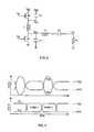
- FIG. 1is a schematic diagram of a conventional Class E amplifier. As shown, a transistor M 1 is connected between ground and an inductor L 1 which is connected to a voltage source V dd . The gate of the transistor M 1 is connected to an input signal Vi. The connection of the transistor M 1 and the inductor L 1 forms a node labeled Vd.
- the switching device M 1as well as other switching devices described may be comprised of any suitable switching devices, for example, MOSFETs or other transistor types.
- a capacitor C 1is connected between Vd and ground.
- the amplifierincludes a transformation network consisting of inductor L 2 and capacitor C 2 . The capacitor C 2 is connected to a load R L at output node V o .
- FIG. 2is a timing diagram illustrating the input signal Vi and the resulting voltage at Vd.
- the input signal Viis a square wave signal switching between ground and V dd .
- V ddthe transistor M 1 is turned on, holding Vd to ground.
- the transistor M 1turns off and the voltage at Vd rises above V dd .
- the transistor M 1must sustain this high drain-to-source voltage. After peaking, the voltage at Vd decreases until it reaches ground. In a typical prior art Class E design, this peak voltage is approximately 3.6 V dd .
- the peak voltagecan be reduced slightly, it can not be decreased below about 2.5 V dd since the average voltage at Vd must equal V dd .
- Designs such as that shown in FIG. 1are not well suited to certain device technologies, such as CMOS, where transistor breakdown voltages are only slightly higher than the supply voltage.
- Another problem relating to amplifiersrelates to the use of differential circuits. It is difficult to perform differential-to-single-ended conversion when a single ended load is required with high efficiency. Therefore, there is a need for improved differential-to-single-ended conversion designs.
- Another problem relating to amplifiersrelates to detecting the output power of an amplifier for purposes of controlling the output power of the amplifier. For example, in a power regulation circuit for a cellular telephone power amplifier, there is a need to sense the power delivered to the antenna. The sensed power is used to help control the output power of the power amplifier.
- An apparatus of the inventionfor a circuit for generating a control signal for controlling the output power of a power amplifier of a wireless device by comprising: a power detector coupled to the output of the power amplifier for generating a detector output signal; and a variable gain amplifier coupled to the power detector for amplifying the detector output signal to a desired level, wherein the value of the control signal generated by the circuit is a function of the gain of the variable gain amplifier.
- Another embodiment of the inventionprovides a method of controlling the output power of an RF power amplifier comprising the steps of: detecting the output power of the RF power amplifier and generating a first signal from the detected output power; amplifying the first signal using a variable gain amplifier; generating a gain control signal from the output of the amplifier and from a reference signal; using the gain control signal to set the gain of the amplifier; generating a second signal by conditioning the gain control signal; and using the second signal to control the output power of the RF power amplifier.
- One embodimentincludes an integrated circuit for use with an external directional coupler comprising: an RF power amplifier formed on the integrated circuit, wherein the integrated circuit is configured such that an external directional coupler can be used to generate a detector signal based on the output power of the RF power amplifier; and a power detector formed on the same integrated circuit to generate an output signal based on the detector signal.
- FIG. 1is a schematic diagram of a prior art Class E amplifier.
- FIG. 2is a timing diagram illustrating the voltage at V D relative to the input signal V I for the prior art Class E amplifier shown in FIG. 1 .
- FIG. 3is a block diagram illustrating an example of an environment in which a power amplifier of the present invention may be used.
- FIG. 4is a schematic diagram of one embodiment of a power amplifier of the present invention.
- FIG. 5is a timing diagram illustrating the voltages present in the amplifier shown in FIG. 4 , relative to the input signals.
- FIG. 6is a schematic diagram of an embodiment of a power amplifier of the present invention with a load connected differentially.
- FIG. 7is a schematic diagram of an embodiment of a power amplifier of the present invention connected to a single-ended load.
- FIG. 8is a schematic diagram of an embodiment of a power amplifier of the present invention connected differentially.
- FIG. 9is a timing diagram illustrating the voltages present in the amplifier shown in FIG. 8 .
- FIG. 10is a schematic diagram of an embodiment of a power amplifier of the present invention.
- FIG. 11is a schematic diagram of another embodiment of a power amplifier of the present invention.
- FIG. 12is a schematic diagram of an embodiment of a power amplifier of the present invention having a preamplifier circuit.
- FIG. 13is a timing diagram illustrating the voltages present in the amplifier shown in FIG. 12 .
- FIG. 14is a schematic diagram of an embodiment of a two-stage differential power amplifier of the present invention.
- FIG. 15is a schematic diagram of a prior art circuit used for performing differential-to-single-ended conversion.
- FIG. 16is a block diagram of a differential-to-single-ended conversion and impedance transformation circuit of the present invention.
- FIG. 17is a schematic diagram of a differential-to-single-ended conversion and impedance transformation circuit of the present invention.
- FIGS. 18 and 19are schematic diagrams illustrating differential inputs AC-coupled from a load.
- FIG. 20is a block diagram of a differential-to-single-ended conversion and impedance transformation circuit having multiple differential inputs.
- FIG. 21is a block diagram of a voltage regulator of the present invention.
- FIG. 22is a schematic diagram of an embodiment of a voltage regulator of the present invention.
- FIG. 23is a schematic diagram of an embodiment of a voltage regulator of the resent invention.
- FIG. 24is a schematic diagram of an embodiment of a voltage regulator of the present invention.
- FIG. 25is an isometric view illustrating how a device of the present invention is packaged.
- FIG. 26is a side view of the device shown in FIG. 25 .
- FIG. 27is a diagram illustrating a ceramic chip carrier with an inductor formed in the carrier.
- FIG. 28is a diagram illustrating a ceramic chip carrier with a vertically-formed inductor formed in the carrier.
- FIG. 29is an electrical schematic diagram of inductors connected between four connection points.
- FIG. 30is a diagram illustrating an example of how the inductors shown in FIG. 29 could be formed in a ceramic chip carrier.
- FIG. 31is a schematic diagram of a prior art power detector.
- FIG. 32is a plot illustrating V SENSE as a function of the output power of the amplifier shown in FIG. 31 .
- FIG. 33is a block diagram of a circuit for controlling the output power of an RF power amplifier.
- FIGS. 34 and 35illustrate examples of circuitry for sensing and controlling the output power of an RF power amplifier.
- FIG. 36is a plot illustrating V SENSE as a function of the output power of the amplifier shown in FIG. 33 .
- FIG. 37is a plot illustrating the sense error for the circuitry shown in FIG. 34 at various output levels.
- a power amplifier of the present inventionmay be used as an amplifier for use with a wireless transmission system such as a wireless telephone or other device.
- the inventionmay also be applied to other applications, including, but not limited to, RF power amplifiers.
- a wireless devicesuch as a cellular telephone
- the devicemay include a transceiver, an antenna duplexer, and an antenna. Connected between the transceiver and the antenna duplexer is an RF power amplifier for amplifying signals for transmission via the antenna.
- an RF power amplifierfor amplifying signals for transmission via the antenna.
- the inventionmay be used in any other application requiring a power amplifier.
- the inventionmay be applied to GSM or other constant envelope modulation systems.
- FIG. 3is a block diagram illustrating an example of an environment in which a power amplifier of the present invention may be used.
- FIG. 3shows a power amplifier 310 connected to a pair of input signals V in and V ip .
- the input signalscome from an input 312 from an input network such as the transceiver chip mentioned above.
- An input bufferis formed by a plurality of inverters X 1 and X 2 which are connected to the input 312 as shown.
- the input buffer circuitcould also be comprised of more or less inverters, or any other suitable circuitry.
- the power amplifier 310is also connected to a voltage regulator 314 which provides a regulated voltage source V dd from a voltage source, such as battery voltage VB.
- the power amplifier 310is also connected to a transformation network 316 which is connected to a load 318 .
- the connection between power amplifier 310 and the transformation network 316may be comprised of a single or multiple connections.
- FIG. 3is shown with n connections.
- the load 318may be comprised of an antenna. Note that the components shown in FIG. 3 are optional and are not essential to the power amplifier 310 .
- FIG. 4is a schematic diagram of one embodiment of a power amplifier of the present invention.
- the power amplifierincludes a switching device M 1 connected between ground and the node labeled V dn .
- the gate of the switching device M 1is connected to the input signal V in .
- Another switching device M 2is connected between the voltage source V dd and a node labeled V dp .
- the gate of the switching device M 2is connected to the input signal V ip .
- Connected between the switching devices M 2 and M 1is an inductor L 1 .
- FIG. 4also shows a capacitor C 1 connected between V dn and ground.
- a capacitor C 3is connected between V dp and Vdd.
- the capacitors C 1 and C 3may be comprised of a combination of separate capacitors and parasitic capacitances of the switching devices M 1 and M 2 .
- the power amplifier shown in FIG. 4also includes a reactive network connected between V dn and the amplifier output V o .
- the reactive networkis formed by inductor L 2 and capacitor C 2 and can be used for filtering or impedance transformation.
- a load R Lis connected to the amplifier output V o .
- FIG. 4resembles a push-pull amplifier topologically, but is fundamentally different, in that the input signals V in and V ip are inverses of one another. Since switching device M 1 is an n-channel device and switching device M 2 is a p-channel device, the switching devices M 1 and M 2 are both turned on and turned off during the same time intervals.
- FIG. 5is a timing diagram illustrating the voltages present in the amplifier shown in FIG. 4 , relative to the input signals.
- FIG. 5shows the input signals V in and V ip which are 180° out of phase with each other. In other words, when one of the input signals is high, the other is low.
- phase 1(V in high and V ip low), the switching devices M 1 and M 2 are both turned on so that V dp and V dn are clamped to V dd and ground respectively.
- phase 2(V in low and V ip high), the switching devices M 1 and M 2 are both turned off.
- the voltage at V dnrises and begins to ring at a frequency determined by the values of the components L 1 , C 1 , C 3 , L 2 , and C 2 . For the best efficiency, these components are chosen so that V dn rises and then returns to ground immediately before the end of phase 2.
- the voltage at V dpfalls and rings in a similar way.
- the voltage at node V dprises back to V dd immediately before the end of phase 2, when switching devices M 1 and M 2 are turned on.
- the peak voltages present across the switching devices M 1 and M 2can be adjusted as desired by changing the passive component values in the circuit under the constraint that the average voltage of V dn must equal that of V dp . If this average voltage lies at V dd /2 then the peak value of V dn will be only slightly higher than V dd and that of V dp will be only slightly lower than ground.
- the duty cycle of the input signals V in and V ip waveformscan be adjusted to reduce the peak voltages even further. As a result, this configuration eliminates the large signal swings that transistors are subjected to in the prior art.
- FIG. 4does not take full advantage of the signal swing that occurs on node V dp .
- An increase in efficiencycan be achieved by making use of the signal swing on both V dp and V dn . This can be accomplished by connecting the load differentially across nodes V dp and V dn as shown in FIG. 6 .
- FIG. 6shows a power amplifier similar to that shown in FIG. 4 .
- the power amplifierincludes switching devices M 1 and M 2 , inductor L 1 , and capacitors C 1 and C 3 .
- a transformation network 616is connected to both nodes V dp and V dn .
- a load R Lis connected to the transformation network 616 .
- the waveforms for the power amplifier shown in FIG. 6are similar to those for the power amplifier shown in FIG. 4 . In this embodiment, the current flowing through the load R L is determined by the difference between the voltages on V dp and V dn .
- FIG. 7shows a power amplifier with two capacitors C 2 and C 4 and an inductor L 3 connected as shown between V dn and V o .
- An inductor L 2is connected between V dp and the connection point of the capacitors C 2 and C 4 .
- a single-ended load R Lis connected between V o and ground.
- the waveforms for the power amplifier shown in FIG. 7are similar to those for the power amplifier shown in FIG. 4 .
- the current flowing to the output from V dp and current flowing to the output from V dnadd when they are summed in phase at the load.
- the loadis AC coupled from either V dp or V dn by capacitor C 4 .
- the inductor L 2 and capacitor C 2can also be chosen to transform the load impedance R L into a desired impedance so that power delivered to the load can be adjusted independently from the voltage swing on Vdp and Vdn. In this case, the voltage swing on V o will vary from that on V dp and V dn as determined by the selection of C 2 and L 2 . Since the combination of L 2 and C 2 is a tuned circuit, it provides some bandpass filtering. If additional filtering is desired, capacitor C 4 and inductor L 3 can also be used as an additional bandpass filter.
- L 2 and C 2 in the configuration of FIG. 7simultaneously perform the functions of impedance transformation, filtering, and differential-to-single-ended conversion.
- the amplifier of the present inventionmay also be implemented differentially using two amplifiers (such as the amplifier shown in FIG. 7 ) connected together as shown in FIG. 8 .
- FIG. 8shows a first amplifier (the positive side) comprised of switching devices M 1 + and M 2 +, inductor L 1 +, capacitors C 1 + and C 3 +, and a transformation network comprised of capacitors C 2 + and C 4 + and inductors L 2 + and L 3 .
- a second amplifier(the negative side) is comprised of switching devices M 1 ⁇ and M 2 ⁇ , inductor L 1 ⁇ , capacitors C 1 ⁇ and C 3 ⁇ , and a transformation network comprised of capacitors C 2 ⁇ and C 4 ⁇ and inductors L 2 ⁇ and L 3 .
- FIG. 9is a timing diagram illustrating the voltages present at the nodes V dn+ , V dp+ , V dn ⁇ , and V dp ⁇ .
- the values of the passive components in the amplifier shown in FIG. 8may be chosen so that the resulting currents from both amplifiers sum in phase at the load R L -.
- the advantages of the power amplifier shown in FIG. 8are similar to the advantages common to differential circuits in general. For example, undesired interference from supply or substrate noise is common-mode. Another advantage is that the impact of supply resistance is reduced because the supply current flows during both clock phases.
- the load R L shown in FIG. 8could be connected to only two of the four output nodes of the power amplifier.
- a configuration similar to that shown in FIG. 4could be connected differentially to the load R L , where the nodes V dp+ and V dp ⁇ are not connected to V o .
- FIG. 8also shows an alternate embodiment where an optional inductor L 4 is connected (shown in dashed lines) between nodes V dp+ and Vdp ⁇ . Without the optional inductor L 4 , the voltage swings on nodes Vdp+, Vdp ⁇ , Vdn+ and Vdn ⁇ and the values of capacitors C 1 +, C 1 ⁇ , C 3 + and C 3 ⁇ can not be independently adjusted.
- the optional inductor L 4has the advantage that these voltage swings can be adjusted independently of the capacitance values mentioned above.
- the capacitors C 1 and C 3 described aboveare used to shape the waveforms of the voltages on V dp and V dn .
- these capacitancesmay be provided by separate capacitors or by the parasitic capacitances of switching devices M 1 and M 2 .
- these capacitancesare formed by switching devices in a way that improves the efficiency of the amplifier.
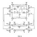
- FIG. 10is a schematic diagram of a power amplifier similar to the amplifier shown in FIG. 8 .
- the capacitors C 1 + and C 3 +are replaced by switching devices M 3 ⁇ and M 4 ⁇ , respectively.
- the capacitors C 1 ⁇ and C 3 ⁇are replaced by switching devices M 3 + and M 4 +, respectively.
- Each of the switching devices M 3 and M 4are driven as shown by a voltage from the opposite amplifier.
- the switching device M 4 +is driven by the voltage at V dp ⁇ on the negative side.
- the switching device M 4 ⁇is driven by the voltage at V dp+ on the positive side.
- the switching device M 3 +is driven by the voltage at V dn ⁇ while the switching device M 3 ⁇ is driven by the voltage at V dn+ .
- the waveforms for the amplifier shown in FIG. 10are similar to those described above.
- the amplifier shown in FIG. 10allows the switching devices M 1 + and M 1 ⁇ to be made smaller by an amount equal to the size of switching devices M 3 + and M 3 ⁇ .
- the switching devices M 2 + and M 2 ⁇can be made smaller by an amount equal to the size of switching devices M 4 + and M 4 ⁇ .
- switching devices M 1 and M 2should remain sufficiently large to assure stability of the circuit. A decrease in the size of the switching devices M 1 and M 2 improves the efficiency since the input capacitances that must be driven are smaller. Another advantage to the amplifier shown in FIG.
- V dp ⁇ and V dn ⁇have the correct phase relationship to the waveforms present at V dp+ and V dn+ , despite possible timing variations on the positive inputs (V ip+ , V in+ ) and on the negative inputs (V ip ⁇ , V in ⁇ ).
- FIG. 10also shows an alternate embodiment where an optional inductor L 4 is connected (shown in dashed lines) between nodes V dp+ and V dp ⁇ , similar to the inductor L 4 shown in FIG. 8 . If the optional inductor L 4 is connected, the voltage swings of nodes Vdp+, Vdp ⁇ , Vdn+, and Vdn ⁇ can be chosen independently from the input capacitances of M 4 ⁇ , M 4 +, M 3 ⁇ , M 3 +.
- FIG. 11is a schematic diagram of a power amplifier similar to the amplifier shown in FIG. 10 , but with the inductors L 1 + and L 1 ⁇ replaced.
- Inductor L 1 +is replaced with a pair of inductors L 1 A+ and L 1 B+.
- Inductor L 1 ⁇is replaced with a pair of inductors L 1 A ⁇ and L 1 B ⁇ .
- the node formed by the connection of inductors L 1 A+ and L 1 B+is connected to the node formed by the connection of inductors L 1 A ⁇ and L 1 B ⁇ .
- the embodiment shown in FIG. 11has similar advantages to the embodiment in FIG.
- input buffer circuitrymay be used to drive the gates of the switching devices M 1 and M 2 of the amplifiers described above.
- the efficiencymay be improved if a similar amplifier circuit is used as a preamplifier circuit.
- FIG. 12is an example of an amplifier having a preamplifier circuit.
- FIG. 12shows an amplifier similar to the amplifier shown in FIG. 7 .
- a preamplifieris shown at the input of the amplifier.
- the preamplifieris comprised of switching devices M 5 and M 6 connected between ground and V dd .
- An inductor L 3is connected between the switching devices M 5 and M 6 .
- the preamplifierincludes inputs V ip2 and V in2 .
- the preamplifier circuitreceives input signals V ip2 and V in2 and generates signals V ip and V in for use by the amplifier.
- the preamplifier circuitis similar to the amplifiers described above, except that all of the passive elements except inductor L 3 are eliminated.
- the capacitances required by the preamplifier circuitryare formed from the input capacitances of the gates of switching devices M 1 and M 2 . Of course, other passive elements could be used with the preamplifier circuit.
- FIG. 13is a timing diagram illustrating the waveforms at V in , V ip , V dn , and V dp of FIG. 12 .
- the preamplifier output waveforms V ip and V inhave a shape that makes them well suited for driving the input gates of switching devices M 1 and M 2 in the final stage.
- capacitor C 4could be connected between inductor L 2 and V 0 with capacitor C 2 connected between V dn and V o .
- This alternate configurationfunctions similarly to the configuration shown in FIG. 12 .
- FIG. 14is a schematic diagram of an amplifier using a two-stage differential configuration which provides an increased efficiency over the circuit shown in FIG. 12 .
- the amplifier shown in FIG. 14is similar to the differential amplifier shown in FIG. 10 , with the addition of preamplifier circuitry.
- the inputs V ip+ and V in+ of the amplifierare connected to preamplifier circuitry comprised of switching devices M 5 + and M 6 +.
- the switching devices M 5 + and M 6 +are connected between ground and V dd , with an inductor L 3 + connected between them.
- Capacitancesare provided to nodes V dp2+ and V dn2+ by switching devices M 8 + and M 7 +, respectively.
- the negative side of the amplifieris configured in the same manner.
- the positive and negative sides of the preamplifier circuitryare cross-coupled in the same way as the amplifier circuitry shown in FIG. 10 (described above).
- the input capacitances of the NMOS and PMOS switching devices M 1 and M 2 of the power amplifier, the input capacitances of the preamplifier switching devices M 7 and M 8 , and the value of inductor L 5can be adjusted so that the signals at V dp2 and V dn2 have the desired peak amplitudes.
- Another aspect of the present inventionrelates to a circuit and method of providing differential-to-single ended output conversion and impedance transformation from differential signals.
- Differential circuitshave a number of advantages that are well known. For example, the impact from noise sources is reduced since these signals are common-mode (i.e., the positive and negative sides are effected identically). In addition, even-order harmonics are reduced because of circuit symmetry. Because of these and other advantages, a differential configuration may be desirable even when the load is single-ended. If a single-ended load is needed, circuitry for differential-to-single-ended conversion is needed.
- FIG. 15shows a prior art circuit used for performing differential-to-single-ended conversion using a transformer T 1 .
- the primary side of the transformer T 1is connected to a first differential input V + and a second differential input V ⁇ .
- the secondary side of the transformer T 1is connected to ground and an output node V O .
- a load Z Lis connected between ground and the output node V O . If the transformer has a 1-to-1 turns ratio, then the differential signals V + and V ⁇ are translated into a signal having an amplitude of (V + ⁇ V ⁇ ) across the load Z L .
- impedance matching or impedance transformationis needed to transform a given load impedance into a different impedance seen by the driver.
- Impedance transformationcan be accomplished, as part of the differential-to-single ended conversion, using the transformer circuit shown in FIG. 15 by adjusting the winding ratio of the transformer T 1 .
- transformers for differential-to-single-ended conversion and impedance transformationhas disadvantages. First, high quality transformers are larger and more costly than other passive elements and are not easily integrated with other semiconductor circuits. Second, practical transformers have imperfect magnetic coupling which causes a loss of power from input to output.
- FIG. 16shows a block diagram of a differential-to-single-ended conversion and impedance transformation circuit.
- the circuithas a first impedance X 1 coupled between the second differential input signal V ⁇ and an output node V O .
- a second impedance X 2is coupled between the first differential input signal V + and the output node V O .
- a load Z Lis connected between the output node V O and ground.
- FIG. 17illustrates one example of an implementation of the circuit shown in FIG. 16 .
- FIG. 17shows an L-C differential-to-single-ended conversion and impedance transformation circuit.
- the impedance X 1is comprised of a capacitor C 5 which is coupled between the second differential input signal V ⁇ and the output node V O .
- the impedance X 2is comprised of an inductor L 6 which is coupled between the first differential input signal V + and the output node V O .
- V O( V + ⁇ X 1 + V - ⁇ X 2 ) ⁇ ( - j ⁇ ⁇ X 2 ⁇ X 1 + ( X 1 + X 2 ) ⁇ Z L ) ( ( X 1 ⁇ X 2 ) 2 + ( X 1 + X 2 ) 2 ⁇ Z L 2 ) ⁇ Z L .
- the ratio R/Xcan be chosen so that the amplitude of the output V O is either larger or smaller than the amplitude A of the differential input.
- the voltage of the output V Oincreases as the value of X decreases.
- the voltage of the output V Odecreases as the value of X increases.
- FIGS. 18 and 19show examples of a how the differential inputs may be AC-coupled from the load Z L in the example shown in FIG. 17 .
- an additional capacitor C 6is inserted between the output node V O and both the capacitor C 5 and the inductor L 6 .
- the capacitor C 6AC-couples the output node V O from the first and second differential inputs V + and V ⁇ .
- an additional capacitor C 6is inserted between the output node V O and the inductor L 6 .
- the capacitor C 6AC-couples the output node V O from the first differential input V + .
- the capacitor C 1provides AC-coupling between the output node V O from the second differential input V ⁇ .
- FIG. 20shows a differential-to-single-ended conversion and impedance transformation circuit having multiple differential inputs.
- FIG. 20shows differential inputs V 1 through V N , where N is the total number of differential inputs.
- a first impedance X 1is coupled between the differential input V 1 and the output node V O .
- a second impedance X 2is coupled between the differential input V 1 and the output node V O .
- an Nth impedance X Nis coupled between the differential input V N and the output node V O .
- Each of the currents from each differential inputis summed in phase at the output node V O .
- the impedance X j between the jth differential input V j and the output node V Owill depend on its phase with respect to that of other differential inputs.
- Optimal power transfer to the load Z 1occurs when the impedances X j are purely reactive. However, this technique may still be applied when impedance X j is not purely reactive. For example, this might occur when actual inductors and capacitors have a series resistance.
- the RF power amplifier shown in FIG. 3includes a voltage regulator 314 connected between the power amplifier 310 and a source of battery voltage VB to provide a voltage source VDD.
- the voltage regulator 314resides on the same integrated circuit as the power amplifier circuit.
- the function of the voltage regulatoris to provide a source of voltage to the power amplifier and to help control the output power level.
- a base stationmay dictate the power level at which each cell phone should transmit (based on factors such as the physical distance from the base station, for example). Varying the voltage level (VDD) can control the output power of the power amplifier. As the voltage of the voltage source VDD increases, the output power increases. Therefore, by controlling the operation of the voltage regulator, and therefore controlling the voltage of voltage source VDD, the output power of the amplifier can be controlled.
- the power amplifier 310will function with any suitable voltage regulator or voltage source, described below is a detailed description of a suitable voltage regulator.
- FIG. 21is a block diagram of a voltage regulator 544 used to provide a regulated voltage VDD from a voltage source VB, for example, from a battery.
- the regulated voltage VDDis provided to a device 530 .
- the device 530may be any type of device requiring a voltage source including, but not limited to power amplifiers.
- the voltage regulator 544includes an input 546 that is connected to a control signal VSET to control the voltage level VDD provided to the device 530 .
- VSETcontrol signal
- the voltage regulator of the present inventionin the context of its use in an RF power amplifier (such as that shown in FIG. 3 ). However, it is understood that the voltage regulator may be used with any type of amplifier as well as any other type of device requiring a voltage source.
- FIG. 22is a schematic diagram of a first embodiment of a voltage regulator 644 connected to a battery voltage VB.
- the voltage regulator 644is comprised of a device M 9 and an op amp X 4 .
- the op amp X 4includes a first input 646 for connection to a voltage control signal VSET.
- the control signal VSETis an analog voltage signal that is proportional to the desired voltage level.
- the other input to the op amp X 4is connected to the regulated voltage VDD.
- the output of the op amp X 4is connected to the input of the device M 9 .
- FIG. 23is a schematic diagram of another embodiment of a voltage regulator 744 connected to a battery voltage VB.
- the voltage regulator 744is similar to the voltage regulator 644 shown in FIG. 22 with the addition of a second regulator circuit comprised of op amp X 5 , switching device M 10 , and an external resistor R 1 .
- FIG. 23also shows an integrated circuit 770 (dashed lines) to illustrate that the power amplifier is formed on the integrated circuit 770 while the resistor R 1 is not.
- the integrated circuit 770may also be the same integrated circuit on which the device to be powered resides.
- the first regulator circuitis connected in the same manner as the regulator circuit shown in FIG. 22 .
- the op amp X 5 of the second regulator circuitincludes an input VSET 2 for connection to a voltage control signal.
- the other input to the op amp X 5is connected to the regulated voltage VDD.
- the output of the op amp X 5is connected to the gate of the device M 10 .
- the external resistor R 1is connected between the battery voltage VB and the device M 10 .
- FIG. 23also shows voltage control circuitry 776 which has an input 746 connected to the control signal VSET.
- the voltage control circuitry 776uses the signal VSET to create voltage control signals VSET 1 and VSET 2 for use by the first and second regulator circuits. By controlling both regulators, the voltage level VDD can be controlled.
- powercan be dissipated off the integrated circuit 770 (via resistor R 1 ). This results in a reduction of heat generated in the integrated circuit 770 .
- the voltage regulator 744operates as follows. Since it is desired to minimize the amount of power dissipated on the integrated circuit 770 , one goal is to maximize the use of the second regulator circuit (X 5 , M 10 ) in order to maximize power dissipation through the external resistor R 1 . Therefore, voltage control circuitry 776 will enable the second regulator circuit to provide as much power as it can before enabling the first regulator circuit (X 4 , M 9 ). In other words, when more power is required than the second regulator circuit can provide, the first regulator circuit is enabled to provide additional power. In this way, the maximum amount of power will be dissipated through external resistor R 1 .
- FIG. 24is a schematic diagram of another embodiment of voltage regulator 844 having multiple regulators and multiple external resistors.
- the voltage regulator 844is similar to the regulator 744 shown in FIG. 23 , with the addition of a third regulator circuit comprised of device M 11 , op amp X 6 , and external resistor R 2 .
- the third regulator circuitis connected in the same ways as the second regulator circuit, and operates in a similar manner.
- the op amp X 6 of the third regulator circuitincludes an input VSET 3 for connection to a voltage control signal.
- the other input to the op amp X 5is connected to the regulated voltage VDD.
- the output of the op amp X 6is connected to the gate of device M 11 .
- FIG. 24also shows voltage control circuitry 876 which has an input 846 connected to the control signal VSET.
- the voltage control circuitry 876uses the signal VSET to create voltage control signals VSET 1 , VSET 2 , and VSET 3 for use by the regulator circuits.
- By activating the second or third regulatorpower can be dissipated off the integrated circuit 870 (via resistor R 1 and/or R 2 ). This results in a reduction of heat generated in the integrated circuit 870 .
- the voltage regulator 844operates as follows. Since it is desired to minimize the amount of power dissipated on the integrated circuit 870 , one goal is to maximize the use of the second and third regulator circuits in order to maximize power dissipation through the external resistors R 1 and R 2 . Therefore, voltage control circuitry 876 will enable the second and third regulator circuits to provide as much power as it can before enabling the first regulator circuit. In other words, when more power is required than the second and/or third regulator circuit can provide, the first regulator circuit is enabled to provide additional power. In this way, the maximum amount of power will be dissipated through external resistors R 1 and R 2 .
- the values of the resistors R 1 and R 2may be equal, or may be different, depending on the needs of a user.
- the inventionis not limited to the use of one or two external resistors. Additional regulator circuits and external resistors could be added.
- the value of resistor R 1is 0.7 ohms and the value of resistor R 2 is 0.3 ohms.
- CMOS digital systemsit is sometimes desired to provide devices suitable for use with two voltage levels (e.g., 3.3 volts and 5 volts). Therefore, processing technologies have been developed to provide a single integrated circuit having both 0.5 ⁇ m and 0.35 ⁇ m devices.
- a thicker gate oxideresults in a device with a higher breakdown voltage.
- a thinner gate oxideresults in a faster device, but with a lower breakdown voltage.
- the RF amplifier of the present inventiontakes advantage of the availability of dual gate oxide devices by selectively choosing certain gate lengths for various components of the amplifier. For example, it has been discovered that for preprocessing circuitry or pre-driver circuitry, a high speed is desirable and breakdown voltage is not as important. Therefore these devices are designed using a thinner gate oxide. For output state devices, where a high breakdown voltage is more important, the devices are designed using a thicker gate oxide.
- a dual gate oxide deviceis used to create an RF amplifier such as the RF amplifier shown in FIGS. 12 , and 14 .
- One suitable use of dual gate oxides in these amplifiersis to utilize devices having channel lengths of both 0.5 ⁇ m and 0.35 ⁇ m.
- the 0.5 ⁇ m and 0.35 ⁇ m deviceshave gate oxide thicknesses of 140 Angstroms ( ⁇ ) and 70 ⁇ , respectively.
- the predriver devices M 5 and M 6can be chosen with much smaller device widths than the output devices M 1 and M 2 .
- the predriver output signals Vip and Vinare nearly sinusoidal, the voltage difference (Vip ⁇ Vin) varies between about +Vdd and ⁇ Vdd, and the input capacitances of M 1 and M 2 can be chosen so that neither M 5 nor M 6 experiences a voltage drop that is larger than Vdd.
- a high breakdown voltageis not critical for the predriver and devices M 5 and M 6 can be implemented using 0.35 ⁇ m devices.
- switching devices M 1 and M 2 of the final amplifier stageare sized with large device widths so that nodes Vdn and Vdp are strongly clamped to their respective supply voltages of ground and Vdd when these devices are on.
- the voltage difference (Vdp ⁇ Vdn)varies over a range that is larger than that of the predriver and either M 1 , M 2 , or both will experience a voltage drop that is larger than Vdd. Since a higher breakdown voltage is desired from these devices, M 1 and M 2 can each be implemented using 0.5 ⁇ m devices. Since PMOS transistors are typically slower than NMOS transistors and thicker gate oxide devices are slower than thinner gate oxide devices, it is preferable to use a thicker gate oxide for NMOS devices than for PMOS devices.
- An example of the use of dual gate oxide thicknesses for the RF amplifier of FIG. 14includes only NMOS devices with a thick gate oxide.
- Predriver transistors M 5 +, M 5 ⁇ , M 6 +, M 6 ⁇ , M 7 +, M 7 ⁇ , M 8 +, and M 8 ⁇are implemented using 0.35 ⁇ m devices because, as described above, they are not subjected to voltage drops greater than Vdd and breakdown is not a critical concern. As described above, the final amplifier stage experiences larger voltage swings. However these larger swings can be distributed across its NMOS and PMOS devices in such a way that only NMOS devices see a voltage swing larger than Vdd. This is accomplished by adjusting the values of inductors L 1 +, L 1 ⁇ , and L 4 and the input capacitances of devices M 3 +, M 3 ⁇ , M 4 +, and M 4 ⁇ .
- PMOS devices M 2 +, M 2 ⁇ , M 4 +, and M 4 ⁇ in the final amplifier stageare thinner gate oxide devices, whereas NMOS devices M 1 +, M 1 ⁇ , M 3 +, M 3 ⁇ are thicker gate oxide devices.
- the present inventionis not limited to the values described above. For example, as thinner gate oxides become more common, one or both thicknesses may become lower.
- the terms “thicker” or “thinner” in this descriptionare intended to only refer to intentional or significant differences in gate oxide thicknesses.
- the 0.35 ⁇ m devicesmay vary from one another by some small amount depending on manufacturing tolerances.
- a 0.5 ⁇ m deviceis considered to be “thicker” than a 0.35 ⁇ m device.
- this inventionapplies to various CMOS devices and that the RF Amplifier described above is only used as one example of the application of dual gate oxide devices of the present invention.
- Another benefit of the present inventionrelates to how an RF power amplifier of the present invention is packaged.
- the design of an RF amplifierrequires a low inductance and low resistance to the transistors or switching devices.
- RF power amplifier designstypically require a number of passive components such as inductors and capacitors. It is advantageous to integrate these components in the power amplifier package.
- the packaging technique of the present inventionaddresses these concerns by using “flip chip” technology and multi-layer ceramic chip carrier technology.
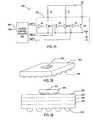
- FIGS. 25 and 26are isometric and side views, respectively, illustrating a packaging technique of the present invention.
- FIGS. 25 and 26show a “flip chip” integrated circuit 970 mounted to a multi-layer ceramic chip carrier 972 .
- the integrated circuit 970includes a plurality of connection points, or “bumps” 974 on the underside of the integrated circuit 970 .
- the ceramic chip carrier 972includes a plurality of connection points or bumps 976 .
- the bumps 974 of the integrated circuit 970are formed by solder and can be mounted to corresponding conductive material formed on the upper surface of the ceramic chip carrier 972 .
- the bumps 976 of the ceramic chip carrier 972are also formed by solder and are used to mount the chip carrier 972 to a printed circuit board (not shown).
- a typical flip chipallows 250 ⁇ m spaced bumps.
- a typical chip carrieralso allows 250 ⁇ m spaced vias for connection to the flip chip bumps 974 .
- 6 ⁇ 6 mm ceramic chip carrierincludes 36 bumps 976 for connection to a PCB. Flip chip and ceramic chip carrier technologies are considered conventional and will not be described in detail.
- Various benefitscan be realized by selectively placing certain components of the RF power amplifier of the present invention on integrated circuit 970 and ceramic chip carrier 972 .
- the inventionwill be described with respect to the RF power amplifier shown in FIG. 14 , although the invention is not limited to power amplifiers.
- all of the switching devicesare formed on the integrated circuit 970 .
- the power transistors(such as switching devices M 1 +, M 1 ⁇ , M 2 +, M 2 ⁇ ) formed on the integrated circuit 970 are preferably placed directly below the bumps 974 of the integrated circuit 970 resulting in low resistance and inductance (as compared to wire bond integrated circuit packages).
- the multi-layer ceramic chip carrier 972is used to build high-Q inductors, transformers, and capacitors. This can be beneficial for CMOS power amplifier architecture since multiple inductors and capacitors may be required. For example, a single band power amplifier may require 4-8 inductors which would be impractical to build on a printed circuit board. In addition, multiple matching networks are used to provide the high transformation ratio required in a push-pull amplifier design.
- the transformers, inductors, capacitors, and other passive devicesare formed on the ceramic chip carrier 972 .
- the ceramic chip carrier 972includes multiple conductive layers 978 (shown as hidden lines) that can be designed to implement these passive devices.
- all of the switching devices and capacitors C 2 + and C 2reside on the integrated circuit 970 , with the inductors L 3 +, L 3 ⁇ , L 5 , L 1 +, L 1 ⁇ , L 4 , L 2 +, and L 2 ⁇ residing on the multi-layer ceramic chip carrier 972 .
- FIG. 27is a diagram illustrating the ceramic chip carrier 972 shown in FIGS. 25 and 26 with a horizontally-formed inductor 1180 formed in the ceramic chip carrier 972 .
- the inductor 1180includes a horizontal loop portion formed by conductive trace 1182 connected to two bumps 974 of the ceramic chip carrier 972 by two vias 1184 .
- One disadvantage with the inductor 1180is that the inductor connection points needs to be close to the edge of the ceramic chip carrier 972 unless the value of the inductor is large enough to route to a lower layer of the ceramic chip carrier 972 .
- FIG. 28is a diagram illustrating the ceramic chip carrier 972 with a vertically-formed inductor 1280 formed in the carrier 972 .
- the inductor 1280is formed in the vertical direction by vias 1284 extending to conductive trace 1286 , which may be formed on a lower level of the carrier 972 .
- the inductor 1280extends downward into the ceramic chip carrier 972 and is coplanar, since the vias 1284 and trace 1286 exist on the same plane.
- the vias 1284may be formed through several layers of the carrier 972 , depending the inductance desired.
- a vertically-formed inductorsuch as the inductor 1280 has two major advantages over horizontally-formed inductors.
- the vertically-formed inductorscan be formed underneath the chip 970 without blocking other routing channels. Therefore, more layout options are available, and more inductors can be formed.
- the vertically-formed vias 1284as opposed to the horizontal conductive trace 1182 , result in less loss at RF frequencies since the vias 1284 have a greater cross-sectional surface area than the conductive traces.
- the vias 1284are substantially cylindrical and have a surface area of ⁇ dL, where d is the diameter of the via 1284 (e.g., 100 ⁇ m) and L is the length of the via.
- the conductive traces, such as conductive trace 1182have a surface area of 2 dL. Therefore, the resistance of a via at RF frequencies is approximately ⁇ /2 less than the resistance of a conductive trace 1182 .
- FIGS. 29 and 30illustrate one embodiment of vertically-formed inductors of the present invention.
- FIG. 29is an electrical schematic diagram showing inductors L 7 , L 8 , L 9 , L 10 , and L 11 connected between connection points 1310 , 1312 , 1314 , and 1316 .
- inductors L 7 and L 8are connected between connection points 1310 and 1312 .
- inductors L 9 and L 10are connected between connection points 1314 and 1316 .
- Inductor L 11is connected between connection points 1318 and 1320 , which are formed between inductors L 9 and L 10 , and L 7 and L 8 .
- FIG. 30illustrates an example of how the circuit of FIG. 29 can be implemented using vertically-formed inductors of the present invention.
- the connection points 1310 , 1312 , 1314 , and 1316are formed at the surface of the ceramic chip carrier (not shown in FIG. 30 ) and will be electrically connected to four of the bumps 974 of the flip-chip 970 .
- the inductorsare formed using the upper two layers of the ceramic chip carrier. Vias 1322 and 1324 extend through both layers where they are connected to an end of conductive traces 1326 and 1328 , respectively, formed in the lower layer of the ceramic chip carrier.
- the opposite ends of the conductive traces 1326 and 1328are connected to vias 1330 and 1332 , respectively, which are also formed in the lower layer of the ceramic chip carrier. Together, the via 1322 , conductive trace 1326 , and via 1330 form inductor L 7 . Similarly, the via 1324 , conductive trace 1328 , and via 1332 form inductor L 9 . The vias 1330 and 1332 are connected to opposite ends of conductive trace 1334 , formed in the upper layer. The conductive trace 1334 forms the inductor L 11 . Finally, vias 1336 and 1338 are connected to the vias 1330 and 1332 , respectively, as well as to opposite ends of the conductive trace 1334 . The vias 1336 and 1338 form the inductors L 8 and L 10 , respectively. While FIGS. 29 and 30 show one specific example of how inductors could be formed in the ceramic chip carrier, it should be understood that other implementations are possible.
- Another benefit of the present inventionrelates to sensing the output power of an RF power amplifier for purposes of controlling the output power.
- an RF power amplifierfor purposes of controlling the output power.
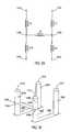
- FIG. 31illustrates a prior art approach for detecting the output power of a power amplifier.
- FIG. 31shows a circuit 3100 including a power amplifier 3110 and an antenna 3112 coupled to the output of the power amplifier 3110 .
- a directional coupler 3114is coupled to sense the output power of the power amplifier 3110 .
- the directional coupler 3114generates a signal V COUP that is rectified by a Schotkey diode D 1 and then filtered by the RC filter (comprised of resistor R 3 and capacitor C 7 ).
- the rectified and filtered signalis provided as an input to a linear amplifier 3116 .
- the amplifier 3116generates a DC signal V SENSE which may be used to control the output power of the power amplifier 3110 .
- the level of V SENSEprovides an indication of the amount of power provided to the antenna 3112 .
- the voltage of V SENSEalso increases.
- FIG. 32is a plot of a curve illustrating V SENSE as a function of the output power (P ANTENNA ) of the power amplifier 3110 .
- the curveis not linear, which can cause problems.
- the non-linear V SENSE curverequires that each device produced (e.g., each cell phone) be calibrated at various power levels. This takes time and increases the ultimate cost of the device.
- Another problem with this prior art approachis that the circuitry is not accurate, especially at lower power levels.
- the temperature sensitivity of the Schotkey diode D 1effects the accuracy of the circuitry.
- FIG. 33is a block diagram of a circuit for controlling the output power of an RF power amplifier.
- FIG. 33shows a power amplifier 3310 and an antenna 3312 coupled to the output of the power amplifier 3310 .
- a power detector(shown in FIG. 33 as directional coupler 3314 ) is coupled to the output of the power amplifier 3310 for sensing the output power of the power amplifier 3310 .
- the directional coupler 3314generates a detector output signal V COUP which is proportional to the output power of the power amplifier 3310 .
- the signal V COUPis provided to a coupler variable gain amplifier (coupler VGA) 3318 .
- Coupler VGAcoupler variable gain amplifier
- the amplified output of the coupler VGA 3318is provided to the input of a sense circuit 3320 .
- the sense circuit 3320may be provided by a circuitry that responds to the envelope the carrier signal. Examples of circuitry suitable for use as sense circuits include, but are not limited to, peak detectors, RMS detector, rectifiers, etc.
- the output of the sense circuit 3320is provided to a first input of an op amp 3322 .
- a second input of the op amp 3322is coupled to a reference voltage (V SET ). Note that “V SET ” referred to with respect to FIGS. 33-35 is a different signal than “VSET” referred to with respect to the earlier figures.
- the op amp 3322generates a gain control signal which is fed back to the coupler VGA 3318 for controlling the gain of the coupler VGA 3318 .
- the gain control signalis also provided to a conditioning circuit 3324 which conditions the gain control signal and generates a DC signal V SENSE .
- the signal V SENSEis provided to control circuitry 3326 .
- the control circuitry 3326is also provided with a signal P SET which relates to a desired output power level of the power amplifier 3310 .
- the output of control circuitry 3326is provided to the power amplifier 3310 to control the output power of the amplifier 3310 .
- the circuit illustrated in FIG. 33(as well as the circuits described below) are designed to approximate logarithmic amplifiers.
- FIGS. 34 and 35illustrate examples of block diagrams of circuitry for sensing and controlling the output power of an RF power amplifier.
- FIG. 34shows a power amplifier 3410 and an antenna 3412 coupled to the output of the power amplifier 3410 .
- a directional coupler 3414is coupled to the output of the power amplifier 3410 for sensing the output power of the power amplifier 3410 .
- the directional coupler 3414generates a signal V COUP which is proportional to the output power of the power amplifier 3410 .
- the signal V COUPis provided to a coupler VGA 3418 .
- An optional capacitor C 8is coupled between the directional coupler 3414 and the coupler VGA 3418 to provide a DC block.
- the coupler VGA 3418 illustrated in FIG. 34is comprised of a multi-stage amplifier.
- the coupler VGA 3418is comprised of six linear variable gain amplifier stages 3430 .
- the output of the coupler VGA 3418is rectified by a sense circuit 3420 .
- the filtered and rectified signalis provided to a first input to of op amp 3422 .
- a fixed-amplitude DC reference voltage (V REF )is provided to a second input of the op amp 3422 .
- the value of V SETis the voltage that is desired at the output of the sense circuit 3420 .
- the op amp 3422generates a gain control signal based on the inputs to the op amp.
- the gain control signalis coupled to each amplifier stage 3430 of the coupler VGA 3418 and controls the gain of each stage 3430 .
- the gain control signalis also coupled to a conditioning circuit 3424 which generates a DC signal V SENSE which is provided to control circuitry 3426 .
- the conditioning circuit 3424conditions the gain control signal to compensate for the non-linearity of the VGA 3418 .
- the conditioning circuit 3424 shown in FIG. 34is comprised of an amplifier 3432 and a DC voltage source that provides an input voltage V REF .
- V SENSEA V ⁇ V REF (1), where A V is the gain of each stage 3430 of the coupler VGA 3418 and is also a function of the gain control signal.
- V SETA V n ⁇ V COUP (Peak ⁇ Peak) (2), where n is the number of stages 3430 of the coupler VGA 3418 .
- V SENSEthe output power of the power amplifier 3410
- P ANTENNAthe output power of the power amplifier 3410
- the V SENSE curveis fairly linear on a log scale. As the number of amplifier stages 3430 increases, the curve will become more linear. Therefore, for any specific application, the number of stages 3430 used is determined not only by the gain required, but also by the desired linearity (i.e., by the acceptable error level).
- the error foundis plotted in FIG. 37 . As shown, the maximum error is approximately 0.6 dbm.
- the acceptable error levelis ⁇ 2 dbm. Therefore, in this example, a 0.6 dbm error would be acceptable. If a smaller maximum error is required, more stages 3430 can be added to the coupler VGA 3418 . Similarly, if a larger error can be tolerated, fewer stages 3430 can be used in the coupler VGA 3418 .
- One advantage of the present inventionis that a 2 point power calibration is possible, as opposed to calibrating a various power levels. Another advantage is that an acceptable accuracy is achieved at lower power levels. Another advantage is that the system is stable independent of ambient temperature variations. This temperature stability results from the feedback loop. Since the error curve for a device is known, another advantage of the present invention is that a simple lookup table can be used to reduce the error even further. The lookup table may be generated based on the transfer function of the curve illustrated in FIG. 37 .
- FIG. 35is a block diagram of a circuit similar to the circuit shown in FIG. 34 .
- the circuit shown in FIG. 35uses an AC reference tone and a second sense circuit to provide the second input to an op amp. By using the reference tone and the second sense circuit, simpler circuitry can be used for the sense circuitry (described below).
- FIG. 35shows a power amplifier 3510 coupled to an antenna 3512 and a directional coupler 3514 coupled to the output of the power amplifier 3510 for generating a signal V COUP .
- the signal V COUPis provided to a coupler VGA 3518 .
- the output of the coupler VGA 3518is rectified and filtered by a sense circuit 3520 .
- the filtered and rectified signalis provided to a first input of op amp 3522 .
- An AC reference tone RFIis provided to a variable limiter 3534 which limits the peak voltage to the value of V SET .
- the output of the variable limiter 3534is rectified and filtered by the sense circuit 3528 and is provided to a second input of the op amp 3522 .
- the op amp 3522generates a gain control signal based on the inputs to the op amp.
- the gain control signalis coupled to each amplifier stage 3530 of the coupler VGA 3518 and controls the gain of each stage 3530 .
- the gain control signalis also coupled to a conditioning circuit 3524 which generates a DC signal V O .
- the conditioning circuit 3524includes first and second sense circuits 3536 and 3538 which each provide an input to an op amp 3540 .
- the output of the op amp 3540provides a signal V O to the control circuitry 3526 for controlling the output of the power amplifier 3510 .
- the AC reference tone RFIis provided to a limiting amplifier 3542 which is powered by a voltage V X resulting in an AC signal with a known amplitude (V X ).
- the output of the limiting amplifier 3542is provided to the second sense circuit 3538 and to an inverter 3544 .
- the inverter 3544is powered by the output (V O ) of the op amp 3540 , resulting in an AC signal with an amplitude of V 0 .
- the output of the inverter 3544is coupled to the input of a VGA 3546 .
- the gain of the VGA 3546like the gain of the VGA stages 3530 , is controlled by the gain control signal from the op amp 3522 .
- the output of the VGA 3546is coupled to the input of the first sense circuit 3536 .
- the conditioning circuit 3524compensates for the non-linearity of the VGA 3518 . Note that, like the sense circuits 3520 and 3528 , the sense circuits 3536 and 3538 may be matched to improve the performance of the invention.
- the signal V Ohas a function similar to the signal V SENSE in FIG. 34 .
- the control circuitry 3526uses V 0 and P SET to set the output power of the power amplifier 3510 to a desired level.
- V OV X A V . ( 4 )
- V SENSEFIG. 34
- V OFIG. 35
- V 0increases as the RF power delivered to the load increases.
- the sense circuitrycan be implemented with simple peak detectors or RMS detectors that match each other, but do not require absolute accuracy.
- the temperature stability of the circuits shown in the Figurescan be improved by matching the sense circuits. At high frequencies, especially in CMOS, it is difficult to build sense circuits that are accurate.
- the sense circuits 3520 and 3528are matched to enhance temperature stability.
- the output of the sense circuit 3520is compared to the reference voltage V SET (via sense circuit 3428 ).
- the reference tone RFImay be provided from an existing signal in the device. For example, RFI could come from the transmit signal of the power amplifier prior to final stage amplification.
- FIGS. 34 and 35provide two examples of suitable conditioning circuits.
- Many types of conditioning circuitscould be used within the spirit and scope of the present invention.
- the conditioning circuitmay be comprised of a linear device (e.g., a wire or a simple gain circuit).
- the conditioning circuitmay be complicated (e.g., the conditioning circuit 3524 shown in FIG. 35 ). Therefore, it is evident that there are a variety of ways that a conditioning circuit could be designed.
- the power amplifier ( 3310 , 3410 , 3510 ) and the coupler VGA ( 3318 , 3418 , 3518 )are formed on a single integrated circuit.
- the power amplifier and coupler VGAmay also be packaged using the packaging techniques described above (see FIGS. 25 - 26 ).
- a “flip chip” integrated circuitmay be mounted to a multi-layer ceramic chip carrier.
- all of the components shown in FIGS. 33 , 34 , or 35 except the directional couplerare formed on an integrated circuit with the directional coupler formed separately, such as on a ceramic chip carrier.
Landscapes
- Engineering & Computer Science (AREA)
- Power Engineering (AREA)
- Microelectronics & Electronic Packaging (AREA)
- Physics & Mathematics (AREA)
- Condensed Matter Physics & Semiconductors (AREA)
- General Physics & Mathematics (AREA)
- Computer Hardware Design (AREA)
- Amplifiers (AREA)
Abstract
Description
The power PLdelivered to the load ZLis given by the following equation:
Differential-to-single-ended conversion is achieved if the impedances X1and X2have opposite signs. Impedances X1and X2may be comprised of any combination of reactive elements (e.g., capacitor C5 and inductor L6 shown in
VSENSE=AV·VREF (1),
where AVis the gain of each
VSET=AVn·VCOUP(Peak−Peak) (2),
where n is the number of
Note that while VSENSE(
Claims (31)
Priority Applications (1)
| Application Number | Priority Date | Filing Date | Title |
|---|---|---|---|
| US10/673,956US6927630B2 (en) | 2000-09-12 | 2003-09-29 | RF power detector |
Applications Claiming Priority (3)
| Application Number | Priority Date | Filing Date | Title |
|---|---|---|---|
| US09/660,123US6549071B1 (en) | 2000-09-12 | 2000-09-12 | Power amplifier circuitry and method using an inductance coupled to power amplifier switching devices |
| US09/842,456US6727754B2 (en) | 2000-09-12 | 2001-04-26 | RF power detector |
| US10/673,956US6927630B2 (en) | 2000-09-12 | 2003-09-29 | RF power detector |
Related Parent Applications (2)
| Application Number | Title | Priority Date | Filing Date |
|---|---|---|---|
| US09/660,123Continuation-In-PartUS6549071B1 (en) | 2000-09-12 | 2000-09-12 | Power amplifier circuitry and method using an inductance coupled to power amplifier switching devices |
| US09/842,456ContinuationUS6727754B2 (en) | 2000-09-12 | 2001-04-26 | RF power detector |
Publications (2)
| Publication Number | Publication Date |
|---|---|
| US20040075499A1 US20040075499A1 (en) | 2004-04-22 |
| US6927630B2true US6927630B2 (en) | 2005-08-09 |
Family
ID=24648237
Family Applications (12)
| Application Number | Title | Priority Date | Filing Date |
|---|---|---|---|
| US09/660,123Expired - LifetimeUS6549071B1 (en) | 2000-09-12 | 2000-09-12 | Power amplifier circuitry and method using an inductance coupled to power amplifier switching devices |
| US09/842,456Expired - LifetimeUS6727754B2 (en) | 2000-09-12 | 2001-04-26 | RF power detector |
| US10/390,935Expired - LifetimeUS6788141B2 (en) | 2000-09-12 | 2003-03-18 | Power amplifier circuitry and method |
| US10/448,963Expired - LifetimeUS6816011B2 (en) | 2000-09-12 | 2003-05-30 | RF power amplifier and method for packaging the same |
| US10/673,956Expired - LifetimeUS6927630B2 (en) | 2000-09-12 | 2003-09-29 | RF power detector |
| US10/813,589Expired - Fee RelatedUS8149064B2 (en) | 2000-09-12 | 2004-03-30 | Power amplifier circuitry and method |
| US10/812,858AbandonedUS20050052167A1 (en) | 2000-09-12 | 2004-03-30 | Power amplifier circuitry and method |
| US10/812,853AbandonedUS20050052235A1 (en) | 2000-09-12 | 2004-03-30 | Power amplifier circuitry and method |
| US10/813,566AbandonedUS20050052236A1 (en) | 2000-09-12 | 2004-03-30 | Power amplifier circuitry and method |
| US10/983,974Expired - Fee RelatedUS7224232B2 (en) | 2000-09-12 | 2004-11-08 | RF power amplifier and method for packaging the same |
| US11/468,354Expired - Fee RelatedUS7935990B2 (en) | 2000-09-12 | 2006-08-30 | RF power amplifier and method for packaging the same |
| US11/931,581Expired - Fee RelatedUS8274330B2 (en) | 2000-09-12 | 2007-10-31 | Power amplifier circuitry and method |
Family Applications Before (4)
| Application Number | Title | Priority Date | Filing Date |
|---|---|---|---|
| US09/660,123Expired - LifetimeUS6549071B1 (en) | 2000-09-12 | 2000-09-12 | Power amplifier circuitry and method using an inductance coupled to power amplifier switching devices |
| US09/842,456Expired - LifetimeUS6727754B2 (en) | 2000-09-12 | 2001-04-26 | RF power detector |
| US10/390,935Expired - LifetimeUS6788141B2 (en) | 2000-09-12 | 2003-03-18 | Power amplifier circuitry and method |
| US10/448,963Expired - LifetimeUS6816011B2 (en) | 2000-09-12 | 2003-05-30 | RF power amplifier and method for packaging the same |
Family Applications After (7)
| Application Number | Title | Priority Date | Filing Date |
|---|---|---|---|
| US10/813,589Expired - Fee RelatedUS8149064B2 (en) | 2000-09-12 | 2004-03-30 | Power amplifier circuitry and method |
| US10/812,858AbandonedUS20050052167A1 (en) | 2000-09-12 | 2004-03-30 | Power amplifier circuitry and method |
| US10/812,853AbandonedUS20050052235A1 (en) | 2000-09-12 | 2004-03-30 | Power amplifier circuitry and method |
| US10/813,566AbandonedUS20050052236A1 (en) | 2000-09-12 | 2004-03-30 | Power amplifier circuitry and method |
| US10/983,974Expired - Fee RelatedUS7224232B2 (en) | 2000-09-12 | 2004-11-08 | RF power amplifier and method for packaging the same |
| US11/468,354Expired - Fee RelatedUS7935990B2 (en) | 2000-09-12 | 2006-08-30 | RF power amplifier and method for packaging the same |
| US11/931,581Expired - Fee RelatedUS8274330B2 (en) | 2000-09-12 | 2007-10-31 | Power amplifier circuitry and method |
Country Status (6)
| Country | Link |
|---|---|
| US (12) | US6549071B1 (en) |
| EP (1) | EP1329021A2 (en) |
| JP (1) | JP5230054B2 (en) |
| KR (1) | KR100887427B1 (en) |
| AU (1) | AU2001292643A1 (en) |
| WO (1) | WO2002023716A2 (en) |
Cited By (6)
| Publication number | Priority date | Publication date | Assignee | Title |
|---|---|---|---|---|
| US20060245520A1 (en)* | 2005-04-28 | 2006-11-02 | Dejan Mijuskovic | Logic threshold acquisition circuits and methods using reversed peak detectors |
| US20080011861A1 (en)* | 2006-06-30 | 2008-01-17 | Takayuki Ikeda | Semiconductor device |
| US7440734B1 (en)* | 2006-02-06 | 2008-10-21 | Rf Micro Devices, Inc. | Active quadrature radio frequency power detector |
| US20090096533A1 (en)* | 2007-10-16 | 2009-04-16 | Paul Susanne A | Adaptively tuned rf power amplifier |
| US8022734B1 (en) | 2008-08-25 | 2011-09-20 | Peregrine Semiconductor Corporation | Low current power detection circuit providing window comparator functionality |
| US8644776B1 (en) | 2008-08-25 | 2014-02-04 | Peregrine Semiconductor Corporation | Systems and methods for providing improved power performance in wireless communication systems |
Families Citing this family (123)
| Publication number | Priority date | Publication date | Assignee | Title |
|---|---|---|---|---|
| US6549071B1 (en)* | 2000-09-12 | 2003-04-15 | Silicon Laboratories, Inc. | Power amplifier circuitry and method using an inductance coupled to power amplifier switching devices |
| US6917245B2 (en) | 2000-09-12 | 2005-07-12 | Silicon Laboratories, Inc. | Absolute power detector |
| US6701138B2 (en)* | 2001-06-11 | 2004-03-02 | Rf Micro Devices, Inc. | Power amplifier control |
| US6828859B2 (en)* | 2001-08-17 | 2004-12-07 | Silicon Laboratories, Inc. | Method and apparatus for protecting devices in an RF power amplifier |
| US20030058604A1 (en)* | 2001-09-13 | 2003-03-27 | Canagasaby Karthisha S. | Method and apparatus to emulate external IO interconnection |
| US6765377B1 (en) | 2002-01-09 | 2004-07-20 | Xilinx, Inc. | Q-emphasized amplifier with inductor-based bandwidth booster |
| DE10250613B4 (en)* | 2002-10-30 | 2007-02-08 | Advanced Micro Devices, Inc., Sunnyvale | Integrated RF signal level detector usable for automatic power level control |
| DE10250612B4 (en)* | 2002-10-30 | 2014-01-16 | Advanced Micro Devices, Inc. | Automatic power level control circuit for a transceiver |
| US6894565B1 (en) | 2002-12-03 | 2005-05-17 | Silicon Laboratories, Inc. | Fast settling power amplifier regulator |
| US6825559B2 (en) | 2003-01-02 | 2004-11-30 | Cree, Inc. | Group III nitride based flip-chip intergrated circuit and method for fabricating |
| US6972965B2 (en)* | 2003-02-04 | 2005-12-06 | Intel Corporation | Method for integrated high Q inductors in FCGBA packages |
| US6897730B2 (en)* | 2003-03-04 | 2005-05-24 | Silicon Laboratories Inc. | Method and apparatus for controlling the output power of a power amplifier |
| US7489914B2 (en)* | 2003-03-28 | 2009-02-10 | Georgia Tech Research Corporation | Multi-band RF transceiver with passive reuse in organic substrates |
| EP1487100A1 (en)* | 2003-06-09 | 2004-12-15 | STMicroelectronics S.r.l. | Multi-channel power amplifier with channels independently self-configuring bridge or single-ended output, particulary for audio applications |
| US6822511B1 (en)* | 2003-06-27 | 2004-11-23 | Sige Semiconductor Inc. | Integrated power amplifier circuit |
| US6882220B2 (en)* | 2003-06-27 | 2005-04-19 | Sige Semiconductor Inc. | Integrated power amplifier circuit |
| US6917243B2 (en)* | 2003-06-27 | 2005-07-12 | Sige Semiconductor Inc. | Integrated power amplifier circuit |
| EP1496611A1 (en)* | 2003-07-09 | 2005-01-12 | STMicroelectronics S.r.l. | Multi-channel power amplifier self-configuring to a bridge or single-ended output, particularly for audio applications |
| US20050026332A1 (en)* | 2003-07-29 | 2005-02-03 | Fratti Roger A. | Techniques for curvature control in power transistor devices |
| US7171171B1 (en)* | 2003-08-15 | 2007-01-30 | Rf Micro Devices, Inc. | GaAs RF signal detection circuit with operational amplifier |
| US7053718B2 (en)* | 2003-09-25 | 2006-05-30 | Silicon Laboratories Inc. | Stacked RF power amplifier |
| US6998919B2 (en)* | 2003-10-22 | 2006-02-14 | Rf Micro Devices, Inc. | Temperature compensated power amplifier power control |
| US7212070B2 (en)* | 2003-12-22 | 2007-05-01 | Silicon Laboratories Inc. | Circuit and method of reducing noise in an RF power amplifier |
| US7113045B2 (en)* | 2003-12-22 | 2006-09-26 | Silicon Laboratories Inc. | Power amplifier input structure having a differential output |
| US7522892B2 (en)* | 2003-12-22 | 2009-04-21 | Black Sand Technologies, Inc. | Power amplifier with serial interface and associated methods |
| US7064605B2 (en)* | 2003-12-22 | 2006-06-20 | Silicon Laboratories Inc. | Circuit and method of establishing DC bias levels in an RF power amplifier |
| US7161427B2 (en)* | 2003-12-22 | 2007-01-09 | Silicon Laboratories Inc. | Input structure for a power amplifier and associated methods |
| US7502601B2 (en)* | 2003-12-22 | 2009-03-10 | Black Sand Technologies, Inc. | Power amplifier with digital power control and associated methods |
| EP1585217B1 (en)* | 2004-04-08 | 2007-09-19 | STMicroelectronics N.V. | Process of controlling the power of the output signal of an amplifier system, and associated system |
| KR101009673B1 (en)* | 2004-04-14 | 2011-01-19 | 엘지디스플레이 주식회사 | Driving device for light emitting lamp and driving method thereof |
| US7268626B2 (en)* | 2004-04-30 | 2007-09-11 | Broadcom Corporation | Compensating a power amplifier based on operational-based changes |
| DE102004027809B4 (en)* | 2004-06-08 | 2006-10-26 | Infineon Technologies Ag | Frequency converter circuit and frequency converter circuit arrangement |
| US7751784B2 (en)* | 2004-06-30 | 2010-07-06 | Black Sand Technologies, Inc. | Method of protecting power amplifiers |
| US7161423B2 (en)* | 2004-06-30 | 2007-01-09 | Silicon Laboratories Inc. | Parallel power amplifier and associated methods |
| US7751783B2 (en)* | 2004-06-30 | 2010-07-06 | Black Sand Technologies, Inc. | Power amplifier protection circuit and associated methods |
| DE102004039619B3 (en)* | 2004-08-06 | 2005-08-25 | Atmel Germany Gmbh | MOS transistor circuit with active components and high breakdown voltage, distributes input signal synchronously between input connections of circuit |
| KR100651395B1 (en)* | 2004-09-24 | 2006-11-29 | 삼성전자주식회사 | Power amplifier of transmitter |
| US7142053B2 (en)* | 2004-12-06 | 2006-11-28 | Skyworks Solutions, Inc. | Voltage clamp for improved transient performance of a collector voltage controlled power amplifier |
| US7061279B1 (en)* | 2004-12-30 | 2006-06-13 | Broadcom Corporation | System and method for high frequency, high output swing buffers |
| US7342387B1 (en) | 2005-02-24 | 2008-03-11 | National Semiconductor Corporation | System and method for providing a highly efficient wide bandwidth power supply for a power amplifier |
| US7248080B1 (en) | 2005-02-24 | 2007-07-24 | National Semiconductor Corporation | Power supply switching at circuit block level to reduce integrated circuit input leakage currents |
| US7539467B1 (en) | 2005-02-24 | 2009-05-26 | National Semiconductor Corporation | Low leakage IC input structures including slaved standby current shut-off and increased gain for tighter hysteresis |
| US7676239B1 (en) | 2005-02-24 | 2010-03-09 | National Semiconductor Corporation | System and method for providing a power controller with flat amplitude and phase response |
| US7336127B2 (en)* | 2005-06-10 | 2008-02-26 | Rf Micro Devices, Inc. | Doherty amplifier configuration for a collector controlled power amplifier |
| KR100654459B1 (en) | 2005-06-30 | 2006-12-06 | 삼성전자주식회사 | Broadband Low Noise Amplifier and RF Signal Amplification Method Using the Amplifier |
| US7548112B2 (en)* | 2005-07-21 | 2009-06-16 | Cree, Inc. | Switch mode power amplifier using MIS-HEMT with field plate extension |
| US20070031156A1 (en)* | 2005-07-29 | 2007-02-08 | Robotham W S Jr | Amplification of TTL RF oscillator signals with digital logic and power switching technology for CO2 laser RF power supplies |
| US7330071B1 (en) | 2005-10-19 | 2008-02-12 | Rf Micro Devices, Inc. | High efficiency radio frequency power amplifier having an extended dynamic range |
| TWI281027B (en)* | 2005-12-02 | 2007-05-11 | Ind Tech Res Inst | Peak detector |
| KR100747113B1 (en)* | 2006-06-26 | 2007-08-09 | 한국과학기술원 | Power amplifier |
| KR100757371B1 (en)* | 2006-07-07 | 2007-09-11 | 삼성전자주식회사 | Power Amplifier Circuit and Method for Envelope Modulation of High Frequency Signals |
| US7693496B2 (en)* | 2006-09-07 | 2010-04-06 | Infineon Technologies Ag | Polar transmitter arrangement and method |
| US7477105B2 (en) | 2006-09-08 | 2009-01-13 | Infineon Technologies Ag | Amplifier arrangement and method for amplifying a signal |
| US8111001B2 (en) | 2007-07-17 | 2012-02-07 | Cree, Inc. | LED with integrated constant current driver |
| US7760018B2 (en)* | 2007-12-31 | 2010-07-20 | Tialinx, Inc. | High-efficiency switching power amplifiers with low harmonic distortion |
| US9479202B2 (en) | 2008-02-19 | 2016-10-25 | Infineon Technologies Ag | System and method for burst mode amplifier |
| US8994488B2 (en) | 2008-03-12 | 2015-03-31 | Mediatek Inc. | Transformer power splitter having primary winding conductors magnetically coupled to secondary winding conductors and configured in topology including series connection and parallel connection |
| US7777570B2 (en)* | 2008-03-12 | 2010-08-17 | Mediatek Inc. | Transformer power combiner having secondary winding conductors magnetically coupled to primary winding conductors and configured in topology including series connection and parallel connection |
| US8198714B2 (en)* | 2008-03-28 | 2012-06-12 | Broadcom Corporation | Method and system for configuring a transformer embedded in a multi-layer integrated circuit (IC) package |
| US7852063B2 (en)* | 2008-06-04 | 2010-12-14 | Silicon Storage Technology, Inc. | Integrated power detector with temperature compensation for fully-closed loop control |
| CN101714546B (en) | 2008-10-03 | 2014-05-14 | 株式会社半导体能源研究所 | Display device and manufacturing method thereof |
| EP2172977A1 (en)* | 2008-10-03 | 2010-04-07 | Semiconductor Energy Laboratory Co., Ltd. | Display device |
| KR101435501B1 (en) | 2008-10-03 | 2014-08-29 | 가부시키가이샤 한도오따이 에네루기 켄큐쇼 | Display device |
| JP5361651B2 (en) | 2008-10-22 | 2013-12-04 | 株式会社半導体エネルギー研究所 | Method for manufacturing semiconductor device |
| US8741702B2 (en)* | 2008-10-24 | 2014-06-03 | Semiconductor Energy Laboratory Co., Ltd. | Method for manufacturing semiconductor device |
| WO2010047288A1 (en)* | 2008-10-24 | 2010-04-29 | Semiconductor Energy Laboratory Co., Ltd. | Method for manufacturing semiconductordevice |
| KR20160072845A (en) | 2008-10-24 | 2016-06-23 | 가부시키가이샤 한도오따이 에네루기 켄큐쇼 | Semiconductor device and method for manufacturing the same |
| KR101667909B1 (en) | 2008-10-24 | 2016-10-28 | 가부시키가이샤 한도오따이 에네루기 켄큐쇼 | Method for manufacturing semiconductor device |
| US8106400B2 (en) | 2008-10-24 | 2012-01-31 | Semiconductor Energy Laboratory Co., Ltd. | Semiconductor device and method for manufacturing the same |
| EP2180518B1 (en)* | 2008-10-24 | 2018-04-25 | Semiconductor Energy Laboratory Co, Ltd. | Method for manufacturing semiconductor device |
| KR101432764B1 (en)* | 2008-11-13 | 2014-08-21 | 가부시키가이샤 한도오따이 에네루기 켄큐쇼 | Method for manufacturing semiconductor device |
| KR101914404B1 (en) | 2008-11-21 | 2018-11-01 | 가부시키가이샤 한도오따이 에네루기 켄큐쇼 | Semiconductor device |
| US8301091B2 (en)* | 2009-01-30 | 2012-10-30 | Avago Technologies General Ip (Singapore) Pte. Ltd. | Power detector for multi-band network access |
| WO2011010541A1 (en) | 2009-07-18 | 2011-01-27 | Semiconductor Energy Laboratory Co., Ltd. | Semiconductor device and method for manufacturing the same |
| CN102498570B (en) | 2009-09-04 | 2016-02-10 | 株式会社半导体能源研究所 | Light emitting device and manufacturing method thereof |
| WO2011034012A1 (en)* | 2009-09-16 | 2011-03-24 | Semiconductor Energy Laboratory Co., Ltd. | Logic circuit, light emitting device, semiconductor device, and electronic device |
| KR101153568B1 (en)* | 2009-11-02 | 2012-06-11 | 삼성전기주식회사 | Multi-stage cmos power amplifier |
| TWI539741B (en)* | 2009-11-23 | 2016-06-21 | 赫梯微波公司 | Logarithmic mean-square power detector with servo control loop |
| US8008146B2 (en)* | 2009-12-04 | 2011-08-30 | International Business Machines Corporation | Different thickness oxide silicon nanowire field effect transistors |
| US8324973B2 (en)* | 2009-12-08 | 2012-12-04 | Black Sand Technologies, Inc. | Low output impedance RF amplifier |
| DE102010009984A1 (en)* | 2009-12-28 | 2011-06-30 | Rohde & Schwarz GmbH & Co. KG, 81671 | Amplifier module with a compensation element |
| DE102010007451B3 (en)* | 2010-02-10 | 2011-03-17 | Siemens Aktiengesellschaft | Push-pull amplifier for amplifying input signal to output signal, has two amplifying elements, where each amplifying element has current emitting electrode and current collecting electrode |
| US8420455B2 (en) | 2010-05-12 | 2013-04-16 | International Business Machines Corporation | Generation of multiple diameter nanowire field effect transistors |
| US8519479B2 (en) | 2010-05-12 | 2013-08-27 | International Business Machines Corporation | Generation of multiple diameter nanowire field effect transistors |
| US8445337B2 (en) | 2010-05-12 | 2013-05-21 | International Business Machines Corporation | Generation of multiple diameter nanowire field effect transistors |
| US10006948B2 (en)* | 2011-02-25 | 2018-06-26 | Veris Industries, Llc | Current meter with voltage awareness |
| KR101167454B1 (en) | 2011-03-28 | 2012-07-26 | 숭실대학교산학협력단 | Power Amplifier Using Differential Structure |
| JP5838650B2 (en)* | 2011-08-16 | 2016-01-06 | 株式会社ソシオネクスト | Output circuit |
| JP2013084333A (en) | 2011-09-28 | 2013-05-09 | Semiconductor Energy Lab Co Ltd | Shift register circuit |
| KR101897165B1 (en) | 2012-04-17 | 2018-10-23 | 삼성전자주식회사 | Apparatus and method for balanced power amplifing |
| EP2713507B1 (en)* | 2012-10-01 | 2014-12-10 | Nxp B.V. | FET RF power detector |
| US9035194B2 (en)* | 2012-10-30 | 2015-05-19 | Intel Corporation | Circuit board with integrated passive devices |
| US20140167900A1 (en) | 2012-12-14 | 2014-06-19 | Gregorio R. Murtagian | Surface-mount inductor structures for forming one or more inductors with substrate traces |
| US8872587B2 (en)* | 2013-03-06 | 2014-10-28 | International Business Machines Corporation | Generating negative impedance compensation |
| CN103281039B (en)* | 2013-04-15 | 2016-04-27 | 北京大学 | A kind of Time delay control that adopts is released the difference E power-like amplifier of branch road |
| US9407150B2 (en)* | 2013-09-06 | 2016-08-02 | Raytheon Company | High efficiency zero-voltage switching (ZVS) assistance circuit for power converter |
| EP2863429B1 (en) | 2013-10-16 | 2017-06-14 | Telefonaktiebolaget LM Ericsson (publ) | Tunable inductor arrangement, transceiver, method and computer program |
| EP2863428B1 (en)* | 2013-10-16 | 2017-05-17 | Telefonaktiebolaget LM Ericsson (publ) | Tunable inductor arrangement, transceiver, method and computer program |
| CN103701417A (en)* | 2013-12-16 | 2014-04-02 | 联想(北京)有限公司 | Radio frequency amplifying circuit |
| US9654066B2 (en)* | 2014-04-03 | 2017-05-16 | Marvell World Trade Ltd. | Common-source power amplifiers |
| US9385669B2 (en)* | 2014-06-23 | 2016-07-05 | Texas Instruments Incorporated | Class-E outphasing power amplifier with efficiency and output power enhancement circuits and method |
| US9685910B2 (en) | 2014-10-03 | 2017-06-20 | Short Circuit Technologies Llc | Transformer based impedance matching network and related power amplifier, ADPLL and transmitter based thereon |
| US9515014B2 (en)* | 2014-10-08 | 2016-12-06 | Infineon Technologies Americas Corp. | Power converter package with integrated output inductor |
| DE102014118040B4 (en)* | 2014-12-05 | 2017-08-24 | Fraunhofer-Gesellschaft zur Förderung der angewandten Forschung e.V. | Control circuit for a base station for transmitting energy to a receiver by means of an electrical resonant circuit, evaluation device, method and computer program |
| US9473091B2 (en)* | 2015-02-12 | 2016-10-18 | Qualcomm Incorporated | Amplifier with common-mode filter |
| US9543910B2 (en) | 2015-03-06 | 2017-01-10 | Apple Inc. | Radio frequency system switching power amplifier systems and methods |
| US9608613B2 (en) | 2015-06-30 | 2017-03-28 | Synaptics Incorporated | Efficient high voltage square wave generator |
| CN109314496B (en) | 2016-03-14 | 2023-01-17 | 美国亚德诺半导体公司 | Active linearization for wideband amplifiers |
| US10199997B2 (en) | 2016-06-09 | 2019-02-05 | Qualcomm Incorporated | Source-degenerated amplification stage with rail-to-rail output swing |
| DE102016113152B4 (en)* | 2016-07-18 | 2019-12-19 | Semikron Elektronik Gmbh & Co. Kg | Power electronic switching device and power semiconductor module herewith |
| USD876628S1 (en) | 2016-07-20 | 2020-02-25 | Nyxoah S.A. | Medical implant |
| EP3488523B1 (en)* | 2016-07-21 | 2023-10-04 | LG Electronics Inc. | Power converting system |
| USD988519S1 (en) | 2016-09-12 | 2023-06-06 | Nyxoah S.A. | Patch |
| US10333410B2 (en)* | 2016-09-15 | 2019-06-25 | Futurewei Technologies, Inc. | Common-mode (CM) electromagnetic interference (EMI) reduction in resonant converters |
| EP4358401A3 (en) | 2017-01-26 | 2024-07-10 | Analog Devices, Inc. | Bias modulation active linearization for broadband amplifiers |
| US10848109B2 (en) | 2017-01-26 | 2020-11-24 | Analog Devices, Inc. | Bias modulation active linearization for broadband amplifiers |
| EP3589358B1 (en) | 2017-02-28 | 2025-06-04 | Nyxoah S.A. | Surgical implant system |
| US10739424B2 (en)* | 2017-03-27 | 2020-08-11 | Waveguide Corporation | Output impedance calibration of integrated switched-mode power amplifiers |
| IT201800002466A1 (en) | 2018-02-07 | 2019-08-07 | St Microelectronics Srl | INTEGRATED CIRCUIT FOR IMPLEMENTING AN AUDIO AMPLIFIER, RELATIVE AUDIO AMPLIFIER |
| IT201800002464A1 (en) | 2018-02-07 | 2019-08-07 | St Microelectronics Srl | ELECTRONIC CONVERTER, RELATIVE AUDIO SYSTEM, INTEGRATED CIRCUIT AND PROCEDURE FOR OPERATING AN ELECTRONIC CONVERTER |
| CN109639247B (en)* | 2018-12-12 | 2023-07-04 | 上海剑桥科技股份有限公司 | Monitoring control system and method for output power of radio frequency power amplifier |
| US20230179162A1 (en)* | 2021-12-08 | 2023-06-08 | Globalfoundries U.S. Inc. | Differential stacked power amplifier with inductive gain boosting |
| CN115425934B (en)* | 2022-09-09 | 2023-05-09 | 佛山臻智微芯科技有限公司 | Output matching circuit of power amplifier |
Citations (70)
| Publication number | Priority date | Publication date | Assignee | Title |
|---|---|---|---|---|
| US4075574A (en) | 1975-10-16 | 1978-02-21 | Tektronix, Inc. | Wideband differential amplifier |
| US4590436A (en) | 1984-04-27 | 1986-05-20 | Gte Laboratories Incorporated | High voltage, high frequency amplifier circuit |
| US4604532A (en) | 1983-01-03 | 1986-08-05 | Analog Devices, Incorporated | Temperature compensated logarithmic circuit |
| US4649467A (en) | 1985-07-31 | 1987-03-10 | United Technologies Corporation | High efficiency MOSFET sine wave generator |
| US4772856A (en) | 1986-07-30 | 1988-09-20 | Nippon Telegraph And Telephone Corporation | Power amplifier |
| US4808907A (en) | 1988-05-17 | 1989-02-28 | Motorola, Inc. | Current regulator and method |
| US4857865A (en) | 1988-11-10 | 1989-08-15 | Hughes Aircraft Company | Self equalizing multi-stage radio frequency power amplifier |
| US4893030A (en) | 1986-12-04 | 1990-01-09 | Western Digital Corporation | Biasing circuit for generating precise currents in an integrated circuit |
| EP0399561A2 (en) | 1989-05-25 | 1990-11-28 | Hughes Aircraft Company | VHF DC-DC power supply |
| US4990803A (en) | 1989-03-27 | 1991-02-05 | Analog Devices, Inc. | Logarithmic amplifier |
| EP0413348A2 (en) | 1989-08-18 | 1991-02-20 | Mitsubishi Denki Kabushiki Kaisha | Semiconductor integrated circuit |
| US5023566A (en) | 1989-12-21 | 1991-06-11 | General Electric Company | Driver for a high efficiency, high frequency Class-D power amplifier |
| US5118997A (en) | 1991-08-16 | 1992-06-02 | General Electric Company | Dual feedback control for a high-efficiency class-d power amplifier circuit |
| US5159280A (en)* | 1990-03-09 | 1992-10-27 | The General Electric Company, Plc | True logarithmic amplifier having a variable gain amplifier |
| US5274341A (en) | 1991-07-19 | 1993-12-28 | Hitachi, Ltd. | High-frequency power amplifier |
| US5291123A (en) | 1992-09-09 | 1994-03-01 | Hewlett-Packard Company | Precision reference current generator |
| US5298811A (en) | 1992-08-03 | 1994-03-29 | Analog Devices, Inc. | Synchronous logarithmic amplifier |
| US5327337A (en) | 1992-09-01 | 1994-07-05 | Broadcast Electronics, Inc. | Resonant push-pull switching power amplifier |
| US5343162A (en) | 1993-04-06 | 1994-08-30 | At&T Bell Laboratories | RF variable gain tuned output amplifier which maintains high Q in saturation |
| US5345185A (en) | 1992-04-14 | 1994-09-06 | Analog Devices, Inc. | Logarithmic amplifier gain stage |
| US5420537A (en) | 1992-09-15 | 1995-05-30 | Analogic Corporation | High power solid state R.F. amplifier |
| US5434537A (en) | 1993-02-12 | 1995-07-18 | Nokia Mobile Phones Ltd. | Circuit for measuring the output power from an amplifier |
| US5450036A (en) | 1993-02-23 | 1995-09-12 | Rohm Co., Ltd. | Power amplifier circuit for audio signal and audio device using the same |
| DE4419318A1 (en) | 1994-05-20 | 1995-12-07 | Microelectronics Tech Inc | HF single-pole throw switch e.g. for switching satellite signals to receiver |
| US5477188A (en) | 1994-07-14 | 1995-12-19 | Eni | Linear RF power amplifier |
| US5604383A (en) | 1994-05-11 | 1997-02-18 | Fuji Electric Co., Ltd. | Stabilized power supply device using a flip chip as an active component |
| US5612647A (en) | 1995-06-30 | 1997-03-18 | Harris Corporation | RF power amplifier system having an improved drive system |
| US5623231A (en) | 1994-09-26 | 1997-04-22 | Endgate Corporation | Push-pull power amplifier |
| US5625205A (en) | 1993-06-02 | 1997-04-29 | Nec Corporation | Bipolar transistor circuit |
| US5646578A (en) | 1994-12-29 | 1997-07-08 | Lucent Technologies Inc. | Wide dynamic range power amplifier |
| US5648743A (en) | 1993-08-10 | 1997-07-15 | Fujitsu Limited | Amplifying circuit for an integrated circuit with low-noise characteristic |
| US5724003A (en)* | 1995-12-29 | 1998-03-03 | Maxim Integrated Products, Inc. | Methods and apparatus for signal amplitude control systems |
| US5742205A (en) | 1995-07-27 | 1998-04-21 | Scientific-Atlanta, Inc. | Field effect transistor cable television line amplifier |
| WO1998037627A1 (en) | 1997-02-24 | 1998-08-27 | Advanced Energy Industries, Inc. | Series powered, parallel output radio frequency generator |
| US5831331A (en) | 1996-11-22 | 1998-11-03 | Philips Electronics North America Corporation | Self-shielding inductor for multi-layer semiconductor integrated circuits |
| US5867061A (en) | 1996-12-04 | 1999-02-02 | Northern Telecom Limited | Transformer coupled stacked power amplifier |
| US5880631A (en)* | 1996-02-28 | 1999-03-09 | Qualcomm Incorporated | High dynamic range variable gain amplifier |
| US5880635A (en) | 1997-04-16 | 1999-03-09 | Sony Corporation | Apparatus for optimizing the performance of a power amplifier |
| US5942946A (en) | 1997-10-10 | 1999-08-24 | Industrial Technology Research Institute | RF power amplifier with high efficiency and a wide range of gain control |
| US5955926A (en) | 1996-10-04 | 1999-09-21 | Sanyo Electric Co., Ltd. | Power amplifier and chip carrier |
| US5969582A (en) | 1997-07-03 | 1999-10-19 | Ericsson Inc. | Impedance matching circuit for power amplifier |
| US5973368A (en) | 1996-06-05 | 1999-10-26 | Pearce; Lawrence G. | Monolithic class D amplifier |
| US5974041A (en) | 1995-12-27 | 1999-10-26 | Qualcomm Incorporated | Efficient parallel-stage power amplifier |
| US5986500A (en) | 1996-12-30 | 1999-11-16 | Samsung Electronics Co., Ltd. | Combined linear power amplifying device and method |
| US6011438A (en) | 1997-11-27 | 2000-01-04 | Nec Corporation | Push-pull wideband semiconductor amplifier |
| US6016075A (en) | 1997-06-04 | 2000-01-18 | Lord Corporation | Class-D amplifier input structure |
| WO2000016492A1 (en) | 1998-09-10 | 2000-03-23 | Level One Communications, Inc. | A single-chip cmos direct-conversion transceiver |
| US6047167A (en) | 1996-03-01 | 2000-04-04 | Nec Corporation | Output power control device |
| US6069528A (en) | 1997-07-31 | 2000-05-30 | Matsushita Electric Industrial Co., Ltd. | Automatic microwave gain control device |
| US6075995A (en) | 1998-01-30 | 2000-06-13 | Conexant Systems, Inc. | Amplifier module with two power amplifiers for dual band cellular phones |
| US6133793A (en) | 1998-07-27 | 2000-10-17 | Motorola, Inc. | Circuit and method of amplifying a signal for a receiver |
| US6137273A (en) | 1997-10-15 | 2000-10-24 | Em Microelectronic-Marin Sa | Circuit for supplying a high precision current to an external element |
| US6147511A (en) | 1996-05-28 | 2000-11-14 | Altera Corporation | Overvoltage-tolerant interface for integrated circuits |
| US6157258A (en) | 1999-03-17 | 2000-12-05 | Ameritherm, Inc. | High frequency power amplifier |
| US6167134A (en) | 1997-04-22 | 2000-12-26 | Silicon Laboratories, Inc. | External resistor and method to minimize power dissipation in DC holding circuitry for a communication system |
| US6181207B1 (en) | 1998-10-27 | 2001-01-30 | U.S. Philips Corporation | Current amplifier having a low input impedance |
| US6198347B1 (en) | 1999-07-29 | 2001-03-06 | Tropian, Inc. | Driving circuits for switch mode RF power amplifiers |
| US6208875B1 (en) | 1998-04-08 | 2001-03-27 | Conexant Systems, Inc. | RF architecture for cellular dual-band telephones |
| US6208549B1 (en) | 2000-02-24 | 2001-03-27 | Xilinx, Inc. | One-time programmable poly-fuse circuit for implementing non-volatile functions in a standard sub 0.35 micron CMOS |
| US6222788B1 (en) | 2000-05-30 | 2001-04-24 | Micron Technology, Inc. | Vertical gate transistors in pass transistor logic decode circuits |
| US6232634B1 (en) | 1998-07-29 | 2001-05-15 | Motorola, Inc. | Non-volatile memory cell and method for manufacturing same |
| US6236271B1 (en) | 1997-09-30 | 2001-05-22 | Conexant Systems, Inc. | Multi-layer carrier module for power amplifier systems within a digital cellular telephone |
| US6274937B1 (en) | 1999-02-01 | 2001-08-14 | Micron Technology, Inc. | Silicon multi-chip module packaging with integrated passive components and method of making |
| US6319829B1 (en) | 1999-08-18 | 2001-11-20 | International Business Machines Corporation | Enhanced interconnection to ceramic substrates |
| US6323735B1 (en) | 2000-05-25 | 2001-11-27 | Silicon Laboratories, Inc. | Method and apparatus for synthesizing high-frequency signals utilizing on-package oscillator circuit inductors |
| WO2002023716A2 (en) | 2000-09-12 | 2002-03-21 | Silicon Laboratories, Inc. | Power amplifier circuitry and method |
| US6362606B1 (en) | 2000-09-12 | 2002-03-26 | Silicon Laboratories, Inc | Method and apparatus for regulating a voltage |
| US6392488B1 (en) | 2000-09-12 | 2002-05-21 | Silicon Laboratories, Inc. | Dual oxide gate device and method for providing the same |
| US6448847B1 (en) | 2000-09-12 | 2002-09-10 | Silicon Laboratories, Inc. | Apparatus and method for providing differential-to-single ended conversion and impedance transformation |
| US6462620B1 (en) | 2000-09-12 | 2002-10-08 | Silicon Laboratories, Inc. | RF power amplifier circuitry and method for amplifying signals |
Family Cites Families (58)
| Publication number | Priority date | Publication date | Assignee | Title |
|---|---|---|---|---|
| US618207A (en)* | 1899-01-24 | Johannes eduard lang | ||
| US480907A (en)* | 1892-08-16 | James kindred | ||
| US534162A (en)* | 1895-02-12 | Machine for casing an d flavoring tobacco | ||
| US3891926A (en)* | 1972-12-18 | 1975-06-24 | American Standard Inc | Filter module |
| JPS5853521B2 (en)* | 1974-11-15 | 1983-11-30 | ソニー株式会社 | Denryokuzo Fuku Cairo |
| US4067057A (en)* | 1976-06-25 | 1978-01-03 | Pacific Electronic Enterprises Inc. | DC to AC switching converter |
| IT7923475V0 (en)* | 1979-12-24 | 1979-12-24 | Siac Ind Accessori Cavaria Spa | LOCK WITH FUNCTIONAL ELASTIC ELEMENT FROM EJECTOR AND CURSOR RETURN SPRING, FOR BAGS, BRIEFCASES, PURSES AND SIMILAR. |
| JPS57208710A (en)* | 1981-06-17 | 1982-12-21 | Pioneer Electronic Corp | Power amplifier |
| US4689819B1 (en) | 1983-12-08 | 1996-08-13 | Knowles Electronics Inc | Class D hearing aid amplifier |
| JPS62163568A (en) | 1986-01-14 | 1987-07-20 | Kikusui Denshi Kogyo Kk | Switching power source circuit |
| US4670832A (en)* | 1986-06-12 | 1987-06-02 | General Electric Company | Resonant inverter having improved control at enablement |
| US4691270A (en)* | 1986-07-22 | 1987-09-01 | Rca Corporation | Current fed inverter bridge with lossless snubbers |
| IT1213446B (en) | 1986-12-31 | 1989-12-20 | Sgs Microelettronica Spa | INTEGRATED COUPLING CIRCUIT BETWEEN A MODULATOR AND A CERAMIC FILTER FOR RECEIVERS IN AMPLITUDE MODULATION. |
| JPH0783221B2 (en)* | 1987-02-16 | 1995-09-06 | 株式会社安川電機 | Power amplifier for generating magnetic attraction |
| US4755766A (en) | 1987-04-22 | 1988-07-05 | Tektronix, Inc. | Differential to single-ended converter |
| US4871978A (en) | 1988-08-10 | 1989-10-03 | Actel Corporation | High-speed static differential sense amplifier |
| US5105164A (en) | 1989-02-28 | 1992-04-14 | At&T Bell Laboratories | High efficiency uhf linear power amplifier |
| US4994761A (en)* | 1989-11-06 | 1991-02-19 | Motorola Inc. | VHF power amplifier |
| US5113147A (en) | 1990-09-26 | 1992-05-12 | Minnesota Mining And Manufacturing Company | Wide-band differential amplifier using gm-cancellation |
| US5144133A (en)* | 1991-04-04 | 1992-09-01 | Texas Instruments Incorporated | Uncooled infrared detector readout monolithic integrated circuit with individual pixel signal processing |
| US5276910A (en)* | 1991-09-13 | 1994-01-04 | Resound Corporation | Energy recovering hearing system |
| US5311150A (en)* | 1992-09-18 | 1994-05-10 | Tektronix, Inc. | Convertible oscillator circuit |
| US5489176A (en) | 1993-08-23 | 1996-02-06 | Emhart Inc. | Male clinch fastener with cold-formed locking flange and associated installation method |
| US5381112A (en) | 1993-09-22 | 1995-01-10 | Motorola, Inc. | Fully differential line driver circuit having common-mode feedback |
| FR2712126B1 (en)* | 1993-11-05 | 1995-12-01 | Thomson Csf | Power amplifier of the H-bridge type and its blocking means and power amplifier device comprising such amplifiers. |
| JP2831252B2 (en)* | 1993-12-14 | 1998-12-02 | 松下電工株式会社 | Class E push-pull power amplifier circuit |
| JP3460276B2 (en)* | 1993-12-14 | 2003-10-27 | 松下電工株式会社 | Class E push-pull power amplifier circuit |
| JP2831257B2 (en)* | 1994-01-26 | 1998-12-02 | 松下電工株式会社 | Class E push-pull power amplifier circuit |
| US5709959A (en)* | 1994-09-16 | 1998-01-20 | Ricoh Company, Ltd. | Organic thin film electroluminescence device |
| FR2729844B1 (en)* | 1995-01-26 | 1997-11-28 | Sabin Pierre Jean Claude | IMPLANT MEDICAL DEVICE ASSEMBLY FOR ELECTRICAL CONNECTIONS THROUGH THE SKIN |
| US5657219A (en)* | 1995-08-29 | 1997-08-12 | Crown International, Inc. | Opposed current power converter |
| KR100189500B1 (en)* | 1996-01-29 | 1999-06-01 | 구자홍 | Converter of a switched reluctance motor |
| US5874840A (en) | 1996-04-26 | 1999-02-23 | International Business Machines Corporation | Differential source follower with body effect compensation |
| JP3508401B2 (en)* | 1996-07-12 | 2004-03-22 | 富士通株式会社 | Amplifier circuit and multi-stage amplifier circuit |
| US5705959A (en) | 1996-10-08 | 1998-01-06 | The United States Of America As Represented By The Secretary Of The Air Force | High efficiency low distortion amplification |
| JP3204132B2 (en)* | 1996-11-29 | 2001-09-04 | ヤマハ株式会社 | Drive circuit |
| US5768112A (en)* | 1997-05-30 | 1998-06-16 | Delco Electronics Corp. | Sub-resonant series resonant converter having improved form factor and reduced EMI |
| US5982231A (en)* | 1997-07-23 | 1999-11-09 | Linfinity Microelectronics, Inc. | Multiple channel class D audio amplifier |
| US5936466A (en) | 1997-08-04 | 1999-08-10 | International Business Machines Corporation | Differential operational transconductance amplifier |
| US6198352B1 (en) | 1997-11-20 | 2001-03-06 | Applied Micro Circuits Corporation | Radio frequency low noise amplifier fabricated in complementary metal oxide semiconductor technology |
| JP3496752B2 (en)* | 1998-02-19 | 2004-02-16 | シャープ株式会社 | Microwave / millimeter wave equipment |
| US6009023A (en)* | 1998-05-26 | 1999-12-28 | Etron Technology, Inc. | High performance DRAM structure employing multiple thickness gate oxide |
| WO2000003478A1 (en) | 1998-07-08 | 2000-01-20 | Hitachi, Ltd. | High-frequency power amplifier module |
| US6072362A (en)* | 1998-07-10 | 2000-06-06 | Ameritherm, Inc. | System for enabling a full-bridge switch-mode amplifier to recover all reactive energy |
| US6094099A (en) | 1998-10-20 | 2000-07-25 | Trw Inc. | High dynamic range variable gain distributed amplifier |
| US6150852A (en) | 1999-01-14 | 2000-11-21 | Qualcomm Incorporated | Active differential to single-ended converter |
| US6424181B1 (en) | 1999-02-17 | 2002-07-23 | Elbrus International Limited | High-speed low-power sense amplifying half-latch and apparatus thereof for small-swing differential logic (SSDL) |
| US6147886A (en) | 1999-05-15 | 2000-11-14 | Technical Witts, Inc. | Dual opposed interleaved coupled inductor soft switching converters |
| WO2000072606A2 (en)* | 1999-05-25 | 2000-11-30 | Transtek, Inc. | Facility-wide communication system and method |
| US6188274B1 (en)* | 1999-06-04 | 2001-02-13 | Sharp Laboratories Of America, Inc. | Bootstrap capacitor power supply for low voltage mobile communications power amplifier |
| US7555263B1 (en)* | 1999-10-21 | 2009-06-30 | Broadcom Corporation | Adaptive radio transceiver |
| US6362525B1 (en)* | 1999-11-09 | 2002-03-26 | Cypress Semiconductor Corp. | Circuit structure including a passive element formed within a grid array substrate and method for making the same |
| US6300827B1 (en)* | 1999-12-09 | 2001-10-09 | Maxim Integrated Products, Inc. | Method and apparatus for cascaded ground return amplifier |
| US6987425B1 (en) | 2000-05-17 | 2006-01-17 | Marvell International Ltd. | Low phase noise MOS LC oscillator |
| US6355531B1 (en)* | 2000-08-09 | 2002-03-12 | International Business Machines Corporation | Method for fabricating semiconductor devices with different properties using maskless process |
| US7000458B2 (en) | 2001-06-20 | 2006-02-21 | Obayashi Corporation | Weighing equipment for concrete material |
| JP2003078102A (en)* | 2001-09-06 | 2003-03-14 | Mitsubishi Electric Corp | Flip chip amplifier |
| US6894565B1 (en) | 2002-12-03 | 2005-05-17 | Silicon Laboratories, Inc. | Fast settling power amplifier regulator |
- 2000
- 2000-09-12USUS09/660,123patent/US6549071B1/ennot_activeExpired - Lifetime
- 2001
- 2001-04-26USUS09/842,456patent/US6727754B2/ennot_activeExpired - Lifetime
- 2001-09-11EPEP01973020Apatent/EP1329021A2/ennot_activeWithdrawn
- 2001-09-11AUAU2001292643Apatent/AU2001292643A1/ennot_activeAbandoned
- 2001-09-11KRKR1020037003604Apatent/KR100887427B1/ennot_activeExpired - Fee Related
- 2001-09-11JPJP2002527045Apatent/JP5230054B2/ennot_activeExpired - Fee Related
- 2001-09-11WOPCT/US2001/028589patent/WO2002023716A2/enactiveApplication Filing
- 2003
- 2003-03-18USUS10/390,935patent/US6788141B2/ennot_activeExpired - Lifetime
- 2003-05-30USUS10/448,963patent/US6816011B2/ennot_activeExpired - Lifetime
- 2003-09-29USUS10/673,956patent/US6927630B2/ennot_activeExpired - Lifetime
- 2004
- 2004-03-30USUS10/813,589patent/US8149064B2/ennot_activeExpired - Fee Related
- 2004-03-30USUS10/812,858patent/US20050052167A1/ennot_activeAbandoned
- 2004-03-30USUS10/812,853patent/US20050052235A1/ennot_activeAbandoned
- 2004-03-30USUS10/813,566patent/US20050052236A1/ennot_activeAbandoned
- 2004-11-08USUS10/983,974patent/US7224232B2/ennot_activeExpired - Fee Related
- 2006
- 2006-08-30USUS11/468,354patent/US7935990B2/ennot_activeExpired - Fee Related
- 2007
- 2007-10-31USUS11/931,581patent/US8274330B2/ennot_activeExpired - Fee Related
Patent Citations (73)
| Publication number | Priority date | Publication date | Assignee | Title |
|---|---|---|---|---|
| US4075574A (en) | 1975-10-16 | 1978-02-21 | Tektronix, Inc. | Wideband differential amplifier |
| US4604532A (en) | 1983-01-03 | 1986-08-05 | Analog Devices, Incorporated | Temperature compensated logarithmic circuit |
| US4590436A (en) | 1984-04-27 | 1986-05-20 | Gte Laboratories Incorporated | High voltage, high frequency amplifier circuit |
| US4649467A (en) | 1985-07-31 | 1987-03-10 | United Technologies Corporation | High efficiency MOSFET sine wave generator |
| US4772856A (en) | 1986-07-30 | 1988-09-20 | Nippon Telegraph And Telephone Corporation | Power amplifier |
| US4893030A (en) | 1986-12-04 | 1990-01-09 | Western Digital Corporation | Biasing circuit for generating precise currents in an integrated circuit |
| US4808907A (en) | 1988-05-17 | 1989-02-28 | Motorola, Inc. | Current regulator and method |
| US4857865A (en) | 1988-11-10 | 1989-08-15 | Hughes Aircraft Company | Self equalizing multi-stage radio frequency power amplifier |
| US4990803A (en) | 1989-03-27 | 1991-02-05 | Analog Devices, Inc. | Logarithmic amplifier |
| EP0399561A2 (en) | 1989-05-25 | 1990-11-28 | Hughes Aircraft Company | VHF DC-DC power supply |
| EP0413348A2 (en) | 1989-08-18 | 1991-02-20 | Mitsubishi Denki Kabushiki Kaisha | Semiconductor integrated circuit |
| US5023566A (en) | 1989-12-21 | 1991-06-11 | General Electric Company | Driver for a high efficiency, high frequency Class-D power amplifier |
| US5159280A (en)* | 1990-03-09 | 1992-10-27 | The General Electric Company, Plc | True logarithmic amplifier having a variable gain amplifier |
| US5274341A (en) | 1991-07-19 | 1993-12-28 | Hitachi, Ltd. | High-frequency power amplifier |
| US5118997A (en) | 1991-08-16 | 1992-06-02 | General Electric Company | Dual feedback control for a high-efficiency class-d power amplifier circuit |
| US5345185A (en) | 1992-04-14 | 1994-09-06 | Analog Devices, Inc. | Logarithmic amplifier gain stage |
| US5298811A (en) | 1992-08-03 | 1994-03-29 | Analog Devices, Inc. | Synchronous logarithmic amplifier |
| US5327337A (en) | 1992-09-01 | 1994-07-05 | Broadcast Electronics, Inc. | Resonant push-pull switching power amplifier |
| US5291123A (en) | 1992-09-09 | 1994-03-01 | Hewlett-Packard Company | Precision reference current generator |
| US5420537A (en) | 1992-09-15 | 1995-05-30 | Analogic Corporation | High power solid state R.F. amplifier |
| US5434537A (en) | 1993-02-12 | 1995-07-18 | Nokia Mobile Phones Ltd. | Circuit for measuring the output power from an amplifier |
| US5450036A (en) | 1993-02-23 | 1995-09-12 | Rohm Co., Ltd. | Power amplifier circuit for audio signal and audio device using the same |
| US5343162A (en) | 1993-04-06 | 1994-08-30 | At&T Bell Laboratories | RF variable gain tuned output amplifier which maintains high Q in saturation |
| US5625205A (en) | 1993-06-02 | 1997-04-29 | Nec Corporation | Bipolar transistor circuit |
| US5648743A (en) | 1993-08-10 | 1997-07-15 | Fujitsu Limited | Amplifying circuit for an integrated circuit with low-noise characteristic |
| US5604383A (en) | 1994-05-11 | 1997-02-18 | Fuji Electric Co., Ltd. | Stabilized power supply device using a flip chip as an active component |
| DE4419318A1 (en) | 1994-05-20 | 1995-12-07 | Microelectronics Tech Inc | HF single-pole throw switch e.g. for switching satellite signals to receiver |
| US5477188A (en) | 1994-07-14 | 1995-12-19 | Eni | Linear RF power amplifier |
| US5726603A (en) | 1994-07-14 | 1998-03-10 | Eni Technologies, Inc. | Linear RF power amplifier |
| US5623231A (en) | 1994-09-26 | 1997-04-22 | Endgate Corporation | Push-pull power amplifier |
| US5646578A (en) | 1994-12-29 | 1997-07-08 | Lucent Technologies Inc. | Wide dynamic range power amplifier |
| US5612647A (en) | 1995-06-30 | 1997-03-18 | Harris Corporation | RF power amplifier system having an improved drive system |
| US5742205A (en) | 1995-07-27 | 1998-04-21 | Scientific-Atlanta, Inc. | Field effect transistor cable television line amplifier |
| US5974041A (en) | 1995-12-27 | 1999-10-26 | Qualcomm Incorporated | Efficient parallel-stage power amplifier |
| US5724003A (en)* | 1995-12-29 | 1998-03-03 | Maxim Integrated Products, Inc. | Methods and apparatus for signal amplitude control systems |
| US5880631A (en)* | 1996-02-28 | 1999-03-09 | Qualcomm Incorporated | High dynamic range variable gain amplifier |
| US6047167A (en) | 1996-03-01 | 2000-04-04 | Nec Corporation | Output power control device |
| US6147511A (en) | 1996-05-28 | 2000-11-14 | Altera Corporation | Overvoltage-tolerant interface for integrated circuits |
| US5973368A (en) | 1996-06-05 | 1999-10-26 | Pearce; Lawrence G. | Monolithic class D amplifier |
| US5955926A (en) | 1996-10-04 | 1999-09-21 | Sanyo Electric Co., Ltd. | Power amplifier and chip carrier |
| US5831331A (en) | 1996-11-22 | 1998-11-03 | Philips Electronics North America Corporation | Self-shielding inductor for multi-layer semiconductor integrated circuits |
| US5867061A (en) | 1996-12-04 | 1999-02-02 | Northern Telecom Limited | Transformer coupled stacked power amplifier |
| US5986500A (en) | 1996-12-30 | 1999-11-16 | Samsung Electronics Co., Ltd. | Combined linear power amplifying device and method |
| US6384540B1 (en) | 1997-02-24 | 2002-05-07 | Advanced Energy Industries, Inc. | System for high power RF plasma processing |
| WO1998037627A1 (en) | 1997-02-24 | 1998-08-27 | Advanced Energy Industries, Inc. | Series powered, parallel output radio frequency generator |
| US5880635A (en) | 1997-04-16 | 1999-03-09 | Sony Corporation | Apparatus for optimizing the performance of a power amplifier |
| US6167134A (en) | 1997-04-22 | 2000-12-26 | Silicon Laboratories, Inc. | External resistor and method to minimize power dissipation in DC holding circuitry for a communication system |
| US6016075A (en) | 1997-06-04 | 2000-01-18 | Lord Corporation | Class-D amplifier input structure |
| US5969582A (en) | 1997-07-03 | 1999-10-19 | Ericsson Inc. | Impedance matching circuit for power amplifier |
| US6069528A (en) | 1997-07-31 | 2000-05-30 | Matsushita Electric Industrial Co., Ltd. | Automatic microwave gain control device |
| US6236271B1 (en) | 1997-09-30 | 2001-05-22 | Conexant Systems, Inc. | Multi-layer carrier module for power amplifier systems within a digital cellular telephone |
| US5942946A (en) | 1997-10-10 | 1999-08-24 | Industrial Technology Research Institute | RF power amplifier with high efficiency and a wide range of gain control |
| US6137273A (en) | 1997-10-15 | 2000-10-24 | Em Microelectronic-Marin Sa | Circuit for supplying a high precision current to an external element |
| US6011438A (en) | 1997-11-27 | 2000-01-04 | Nec Corporation | Push-pull wideband semiconductor amplifier |
| US6075995A (en) | 1998-01-30 | 2000-06-13 | Conexant Systems, Inc. | Amplifier module with two power amplifiers for dual band cellular phones |
| US6208875B1 (en) | 1998-04-08 | 2001-03-27 | Conexant Systems, Inc. | RF architecture for cellular dual-band telephones |
| US6133793A (en) | 1998-07-27 | 2000-10-17 | Motorola, Inc. | Circuit and method of amplifying a signal for a receiver |
| US6232634B1 (en) | 1998-07-29 | 2001-05-15 | Motorola, Inc. | Non-volatile memory cell and method for manufacturing same |
| WO2000016492A1 (en) | 1998-09-10 | 2000-03-23 | Level One Communications, Inc. | A single-chip cmos direct-conversion transceiver |
| US6181207B1 (en) | 1998-10-27 | 2001-01-30 | U.S. Philips Corporation | Current amplifier having a low input impedance |
| US6274937B1 (en) | 1999-02-01 | 2001-08-14 | Micron Technology, Inc. | Silicon multi-chip module packaging with integrated passive components and method of making |
| US6157258A (en) | 1999-03-17 | 2000-12-05 | Ameritherm, Inc. | High frequency power amplifier |
| US6198347B1 (en) | 1999-07-29 | 2001-03-06 | Tropian, Inc. | Driving circuits for switch mode RF power amplifiers |
| US6319829B1 (en) | 1999-08-18 | 2001-11-20 | International Business Machines Corporation | Enhanced interconnection to ceramic substrates |
| US6208549B1 (en) | 2000-02-24 | 2001-03-27 | Xilinx, Inc. | One-time programmable poly-fuse circuit for implementing non-volatile functions in a standard sub 0.35 micron CMOS |
| US6323735B1 (en) | 2000-05-25 | 2001-11-27 | Silicon Laboratories, Inc. | Method and apparatus for synthesizing high-frequency signals utilizing on-package oscillator circuit inductors |
| US6222788B1 (en) | 2000-05-30 | 2001-04-24 | Micron Technology, Inc. | Vertical gate transistors in pass transistor logic decode circuits |
| WO2002023716A2 (en) | 2000-09-12 | 2002-03-21 | Silicon Laboratories, Inc. | Power amplifier circuitry and method |
| US6362606B1 (en) | 2000-09-12 | 2002-03-26 | Silicon Laboratories, Inc | Method and apparatus for regulating a voltage |
| US6392488B1 (en) | 2000-09-12 | 2002-05-21 | Silicon Laboratories, Inc. | Dual oxide gate device and method for providing the same |
| US6448847B1 (en) | 2000-09-12 | 2002-09-10 | Silicon Laboratories, Inc. | Apparatus and method for providing differential-to-single ended conversion and impedance transformation |
| US6462620B1 (en) | 2000-09-12 | 2002-10-08 | Silicon Laboratories, Inc. | RF power amplifier circuitry and method for amplifying signals |
| US6549071B1 (en) | 2000-09-12 | 2003-04-15 | Silicon Laboratories, Inc. | Power amplifier circuitry and method using an inductance coupled to power amplifier switching devices |
Non-Patent Citations (2)
| Title |
|---|
| Makihara, Chihiro et al., "The Possibility of High Frequency Functional Ceramics Substrate", International Symposium on Multilayer Electronic Ceramic Devices, May 5, 1998 in Cincinnati, Ohio. |
| Sokal, N. O. and Sokal, A. D., "Class E-A new class of high-efficiency tuned single ended switching power amplifiers," IEEE Journal of Solid State Circuits, vol. SC-10, No. 3, Jun. 1975, pp. 168-176. |
Cited By (10)
| Publication number | Priority date | Publication date | Assignee | Title |
|---|---|---|---|---|
| US20060245520A1 (en)* | 2005-04-28 | 2006-11-02 | Dejan Mijuskovic | Logic threshold acquisition circuits and methods using reversed peak detectors |
| US7684518B2 (en)* | 2005-04-28 | 2010-03-23 | Freescale Semiconductor, Inc. | Logic threshold acquisition circuits and methods using reversed peak detectors |
| US7440734B1 (en)* | 2006-02-06 | 2008-10-21 | Rf Micro Devices, Inc. | Active quadrature radio frequency power detector |
| US20080011861A1 (en)* | 2006-06-30 | 2008-01-17 | Takayuki Ikeda | Semiconductor device |
| US7832647B2 (en) | 2006-06-30 | 2010-11-16 | Semiconductor Energy Laboratory Co., Ltd. | Semiconductor device |
| US8261999B2 (en) | 2006-06-30 | 2012-09-11 | Semiconductor Energy Laboratory Co., Ltd. | Semiconductor device |
| US20090096533A1 (en)* | 2007-10-16 | 2009-04-16 | Paul Susanne A | Adaptively tuned rf power amplifier |
| US7911277B2 (en) | 2007-10-16 | 2011-03-22 | Black Sand Technologies, Inc. | Adaptively tuned RF power amplifier |
| US8022734B1 (en) | 2008-08-25 | 2011-09-20 | Peregrine Semiconductor Corporation | Low current power detection circuit providing window comparator functionality |
| US8644776B1 (en) | 2008-08-25 | 2014-02-04 | Peregrine Semiconductor Corporation | Systems and methods for providing improved power performance in wireless communication systems |
Also Published As
| Publication number | Publication date |
|---|---|
| WO2002023716A2 (en) | 2002-03-21 |
| AU2001292643A1 (en) | 2002-03-26 |
| WO2002023716A3 (en) | 2003-02-13 |
| US6788141B2 (en) | 2004-09-07 |
| JP2004526339A (en) | 2004-08-26 |
| US20070096816A1 (en) | 2007-05-03 |
| US20050151591A1 (en) | 2005-07-14 |
| US6816011B2 (en) | 2004-11-09 |
| US20050052236A1 (en) | 2005-03-10 |
| US7935990B2 (en) | 2011-05-03 |
| US20030179045A1 (en) | 2003-09-25 |
| US20050052235A1 (en) | 2005-03-10 |
| US20040075499A1 (en) | 2004-04-22 |
| US20050052167A1 (en) | 2005-03-10 |
| KR100887427B1 (en) | 2009-03-09 |
| KR20030063338A (en) | 2003-07-28 |
| US20080284512A1 (en) | 2008-11-20 |
| JP5230054B2 (en) | 2013-07-10 |
| US8274330B2 (en) | 2012-09-25 |
| US8149064B2 (en) | 2012-04-03 |
| US6549071B1 (en) | 2003-04-15 |
| US20020044018A1 (en) | 2002-04-18 |
| US7224232B2 (en) | 2007-05-29 |
| US20050052237A1 (en) | 2005-03-10 |
| EP1329021A2 (en) | 2003-07-23 |
| US6727754B2 (en) | 2004-04-27 |
| US20030206058A1 (en) | 2003-11-06 |
Similar Documents
| Publication | Publication Date | Title |
|---|---|---|
| US6927630B2 (en) | RF power detector | |
| US7804364B2 (en) | Absolute power detector | |
| US6756849B2 (en) | Absolute power detector | |
| US6448847B1 (en) | Apparatus and method for providing differential-to-single ended conversion and impedance transformation | |
| US7710199B2 (en) | Method and apparatus for stabilizing RF power amplifiers | |
| US7760023B2 (en) | Method and apparatus for stabilizing RF power amplifiers | |
| US7446613B2 (en) | Power amplifier input structure having a differential output | |
| US7372327B2 (en) | Input structure for a power amplifier and associated methods | |
| US6462620B1 (en) | RF power amplifier circuitry and method for amplifying signals | |
| US6392488B1 (en) | Dual oxide gate device and method for providing the same | |
| US8149062B2 (en) | Power amplifier circuitry having inductive networks | |
| US7668526B2 (en) | Frequency mixer using current feedback amplifiers | |
| US20030025556A1 (en) | Differential amplifier providing precisely balanced output signals and having low power consumption |
Legal Events
| Date | Code | Title | Description |
|---|---|---|---|
| STCF | Information on status: patent grant | Free format text:PATENTED CASE | |
| AS | Assignment | Owner name:BLACK SAND TECHNOLOGIES, INC., TEXAS Free format text:ASSIGNMENT OF ASSIGNORS INTEREST;ASSIGNOR:SILICON LABORATORIES INC.;REEL/FRAME:021243/0389 Effective date:20080417 Owner name:BLACK SAND TECHNOLOGIES, INC.,TEXAS Free format text:ASSIGNMENT OF ASSIGNORS INTEREST;ASSIGNOR:SILICON LABORATORIES INC.;REEL/FRAME:021243/0389 Effective date:20080417 | |
| FPAY | Fee payment | Year of fee payment:4 | |
| AS | Assignment | Owner name:COMERICA BANK, TEXAS Free format text:SECURITY AGREEMENT;ASSIGNOR:BLACK SAND TECHNOLOGIES, INC.;REEL/FRAME:022343/0475 Effective date:20071115 Owner name:COMERICA BANK,TEXAS Free format text:SECURITY AGREEMENT;ASSIGNOR:BLACK SAND TECHNOLOGIES, INC.;REEL/FRAME:022343/0475 Effective date:20071115 | |
| FPAY | Fee payment | Year of fee payment:8 | |
| FEPP | Fee payment procedure | Free format text:PAYER NUMBER DE-ASSIGNED (ORIGINAL EVENT CODE: RMPN); ENTITY STATUS OF PATENT OWNER: LARGE ENTITY Free format text:PAYOR NUMBER ASSIGNED (ORIGINAL EVENT CODE: ASPN); ENTITY STATUS OF PATENT OWNER: LARGE ENTITY | |
| AS | Assignment | Owner name:SILICON LABORATORIES, INC., TEXAS Free format text:ASSIGNMENT OF ASSIGNORS INTEREST;ASSIGNORS:DUPUIS, TIMOTHY J.;WELLAND, DAVID R.;NIKNEJAD, ALI M.;AND OTHERS;REEL/FRAME:032913/0394 Effective date:20010424 | |
| AS | Assignment | Owner name:BLACK SAND TECHNOLOGIES, INC., CALIFORNIA Free format text:MERGER;ASSIGNOR:WAVEFORM ACQUISITION CORPORATION;REEL/FRAME:033247/0787 Effective date:20140618 | |
| AS | Assignment | Owner name:BLACK SAND TECHNOLOGIES, INC., TEXAS Free format text:RELEASE OF SECURITY INTEREST;ASSIGNOR:COMERICA BANK;REEL/FRAME:033258/0225 Effective date:20140627 | |
| AS | Assignment | Owner name:BLACK SAND TECHNOLOGIES, INC., TEXAS Free format text:ASSIGNMENT OF ASSIGNORS INTEREST;ASSIGNOR:SILICON LABORATORIES INC.;REEL/FRAME:033500/0122 Effective date:20140612 | |
| AS | Assignment | Owner name:BLACK SAND TECHNOLOGIES INC., CALIFORNIA Free format text:RELEASE OF SECURITY INTEREST;ASSIGNOR:SILICON LABORATORIES INC.;REEL/FRAME:033729/0183 Effective date:20140610 | |
| AS | Assignment | Owner name:QUALCOMM INCORPORATED, CALIFORNIA Free format text:ASSIGNMENT OF ASSIGNORS INTEREST;ASSIGNOR:BLACK SAND TECHNOLOGIES, INC.;REEL/FRAME:034077/0072 Effective date:20141024 | |
| FPAY | Fee payment | Year of fee payment:12 |