US6927384B2 - Method and device for detecting touch pad unit - Google Patents
Method and device for detecting touch pad unitDownload PDFInfo
- Publication number
- US6927384B2 US6927384B2US09/928,967US92896701AUS6927384B2US 6927384 B2US6927384 B2US 6927384B2US 92896701 AUS92896701 AUS 92896701AUS 6927384 B2US6927384 B2US 6927384B2
- Authority
- US
- United States
- Prior art keywords
- light
- amount
- touch pad
- light emitter
- pad device
- Prior art date
- Legal status (The legal status is an assumption and is not a legal conclusion. Google has not performed a legal analysis and makes no representation as to the accuracy of the status listed.)
- Expired - Lifetime
Links
Images


Classifications
- G—PHYSICS
- G06—COMPUTING OR CALCULATING; COUNTING
- G06F—ELECTRIC DIGITAL DATA PROCESSING
- G06F3/00—Input arrangements for transferring data to be processed into a form capable of being handled by the computer; Output arrangements for transferring data from processing unit to output unit, e.g. interface arrangements
- G06F3/01—Input arrangements or combined input and output arrangements for interaction between user and computer
- G06F3/03—Arrangements for converting the position or the displacement of a member into a coded form
- G06F3/033—Pointing devices displaced or positioned by the user, e.g. mice, trackballs, pens or joysticks; Accessories therefor
- G06F3/0354—Pointing devices displaced or positioned by the user, e.g. mice, trackballs, pens or joysticks; Accessories therefor with detection of 2D relative movements between the device, or an operating part thereof, and a plane or surface, e.g. 2D mice, trackballs, pens or pucks
- G06F3/03547—Touch pads, in which fingers can move on a surface
- G—PHYSICS
- G06—COMPUTING OR CALCULATING; COUNTING
- G06F—ELECTRIC DIGITAL DATA PROCESSING
- G06F3/00—Input arrangements for transferring data to be processed into a form capable of being handled by the computer; Output arrangements for transferring data from processing unit to output unit, e.g. interface arrangements
- G06F3/01—Input arrangements or combined input and output arrangements for interaction between user and computer
- G06F3/03—Arrangements for converting the position or the displacement of a member into a coded form
- G06F3/041—Digitisers, e.g. for touch screens or touch pads, characterised by the transducing means
- G06F3/042—Digitisers, e.g. for touch screens or touch pads, characterised by the transducing means by opto-electronic means
- G06F3/0421—Digitisers, e.g. for touch screens or touch pads, characterised by the transducing means by opto-electronic means by interrupting or reflecting a light beam, e.g. optical touch-screen
- G—PHYSICS
- G06—COMPUTING OR CALCULATING; COUNTING
- G06F—ELECTRIC DIGITAL DATA PROCESSING
- G06F2203/00—Indexing scheme relating to G06F3/00 - G06F3/048
- G06F2203/041—Indexing scheme relating to G06F3/041 - G06F3/045
- G06F2203/04109—FTIR in optical digitiser, i.e. touch detection by frustrating the total internal reflection within an optical waveguide due to changes of optical properties or deformation at the touch location
Definitions
- the present inventionrelates generally to a touch sensitive device in an electronic device or a wireless telecommunication terminal.
- a touch padis usually defined as a touch-sensitive user interface area in an electronic device, which allows a user to input information or a command to the device by pressing the touch sensitive area.
- the touch padcan be used as a keypad having a designated functionality.
- a touch padcan be used as an on/off switch and the user can turn the electronic device on or off by pressing the touch sensitive area.
- the touch padcan have several selectable functions.
- the touch padcan be used as a keyboard having a plurality of soft-keys of different functions to allow the user to enter or select one function at a time.
- touch padsit is required to press the pad surface in order to deform it.
- several layers of materialare used to form a grid of vertical and horizontal rows of electrodes.
- An electrical currentis maintained in the grid of electrodes.
- the layersare caused to make contact with each other at the pressing point, thereby interrupting the current in the electrode grid.
- a detection circuitis used to detect the interruption in the current and determine the location of the pressing point on the pad.
- mere touching of the pad surface by a fingeris sufficient. This latter type of touch pad can be of a resistive-type or capacitive-type.
- a thin, electrically conductive and resistive layeris coated on the surface of the touch pad area.
- a coated layerforming a matrix of pixel-like capacitors is provided on the touch sensitive area.
- the location of the pressing pointcan be determined.
- inductive elementsare distributed over the touch pad area.
- a stylus made of an inductive materialis used to change the signals transmitted through the inductive elements for the detection of the presence of the stylus. In some touch pads, if the user moves the touching object around the touch sensitive area and a series of pressing points are registered, the movement of the touching object can also be calculated.
- the electrodes positioned on top of a touch padmay affect the optical transparency of display and/or distort the displayed text or image. Furthermore, some touch pads can be damaged by having dirt or scratches on the touch pad surface.
- surface wave technologyis also used in touch pad applications. In particular, ultrasonic waves propagating on the touch pad surface are used to detect the interruption or absorption of the waves due to touching. While a touch pad using this surface wave technology does not affect the optical quality of the display, it is costly to produce.
- a method of sensing and detecting the presence of an object at a touch pad device having one or more input functions, wherein the touch pad device has a designated interaction area for allowing a user to use the object to interact with the touch pad device to facilitate the input of touch pad functionscomprising the steps of:
- At least one group of optical sensor componentsincluding a first light emitter, a second light emitter and a light receiver in the touch pad device at different locations thereof such that the receiver is capable of receiving a first amount of light emitted by the first light emitter and a second amount of light emitted by the second light emitter; wherein when the object is present at the touch pad device, causes a change in the first amount of light and the second amount of light;
- the first and second emittersare operated in a pulsed mode of a predetermined frequency so that the changes in the first amount of light and second amount of light contain a frequency component so as to distinguish the changes in the first amount of light and second amount of light due to the presence of the object over the changes due to ambient light.
- optical sensor componentscan be placed within the designated interaction area or outside the designated interaction area.
- a touch pad deviceto be used in conjunction with a measurement device, the touch pad device having a designated interaction area for sensing and detecting the presence of an object at the designated interaction area, said touch pad device comprising:
- a light receiverprovided in or near the designated interaction area
- a first light emitter and a second light emitterprovided respectively at a first location and a second different location in the designated interaction such that the receiver is capable of receiving a first amount of light emitted by the first light emitter and a second amount of light emitted by the second light emitter, wherein when the object is present at the touch pad device, causes a change in the first amount of light and the second amount of light, the change in the first amount of light and the change in the second amount of light being separately measured by the measurement device for determining the location of the object in the designated interaction area in relation to the first light emitter and the second light emitter based on the first and second signals.
- the first and second emittersare operated in a pulsed mode of a predetermined frequency so that the changes in the first amount of light and second amount of light contain a frequency component so as to distinguish the changes in the first amount of light and second amount of light due to the presence of the object over the changes due to ambient light.
- the touch pad devicefurther comprises a second group of similar optical sensor components placed in or near the designated interaction area at different locations from the locations of the first and second light emitters and the receiver for further determining the location of the object in the designated interaction area in relation to light emitters in the second group of optical sensor components.
- the optical sensor componentscan be placed inside the designated interaction area or outside the designated interaction area.
- a system for sensing and detecting the presence of an object at a touch pad devicewherein the touch pad device has a designated interaction area for allowing a user to use the object to interact with the touch pad device, said system comprising:
- At least one group of optical sensor componentsincluding a first light emitter, a second light emitter and a light receiver in the touch pad device at different locations thereof such that the receiver is capable of receiving a first amount of light emitted by the first light emitter and a second amount of light emitted by the second light emitter, wherein the first amount of light and the second amount of light are caused to change when the object is present at the touch pad device;
- the first and second emittersare operated in a pulsed mode of a predetermined frequency so that the changes in the first amount of light and second amount of light contain a frequency component so as to distinguish the changes in the first amount of light and second amount of light due to the presence of the object over the changes due to ambient light.
- FIGS. 1 to 15The present invention will become apparent upon reading FIGS. 1 to 15 .
- FIG. 1is a diagrammatic representation showing the general principle of the present invention, where a group of two light emitters and a light receiver is used to detect the presence of a nearby object.
- FIG. 2Ais a diagrammatic representation showing a touch pad device having a group of optical sensor components placed near the top side of the touch pad area.
- FIG. 2Bis a diagrammatic representation showing a touch pad device having a group of optical sensor components placed near the bottom side of the touch pad area.
- FIG. 2Cis a diagrammatic representation showing a touch pad device having a group of optical sensor components placed near the left side of the touch pad area.
- FIG. 2Dis a diagrammatic representation showing a touch pad device having a group of optical sensor components placed near the right side of the touch pad area.
- FIG. 3Ais a diagrammatic representation showing the measurement of the change in the receiver output attributable to one light emitter in a group of optical sensor components.
- FIG. 3Bis a diagrammatic representation showing the measurement of the change in the receiver output attributable to the other light emitter in a group of optical sensor components.
- FIG. 4Ais a diagrammatic representation showing a touch pad device having two groups of optical sensor components separately placed near the top side and the bottom side of the touch pad area.
- FIG. 4Bis a diagrammatic representation showing a touch pad device having two groups of optical sensor components separately placed near the left side and right side of the touch pad area.
- FIG. 5Ais a diagrammatic representation showing a touch pad device of FIG. 4A , wherein one emitter and the receiver near the top side are used for measurement.
- FIG. 5Bis a diagrammatic representation showing a touch pad device of FIG. 4A , wherein another emitter and the receiver near the top side are used for measurement.
- FIG. 5Cis a diagrammatic representation showing a touch pad device of FIG. 4A , wherein one emitter and the receiver near the bottom side are used for measurement.
- FIG. 5Dis a diagrammatic representation showing a touch pad device of FIG. 4A , wherein another emitter and the receiver near the bottom side are used for measurement.
- FIG. 5Eis a diagrammatic representation showing the touch pad device of FIG. 4A , wherein one emitter near the top side and the receiver near the bottom side are used for measurement.
- FIG. 5Fis a diagrammatic representation showing the touch pad device of FIG. 4A , wherein another emitter near the top side and the receiver near the bottom side are used for measurement.
- FIG. 5Gis a diagrammatic representation showing the touch pad device of FIG. 4A , wherein one emitter and the receiver near the top side, and one emitter near the bottom side are used for measurement.
- FIG. 5His a diagrammatic representation showing the touch pad device of FIG. 4A , wherein another emitter and the receiver near the top side, and another emitter near the bottom side are used for measurement.
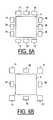
- FIG. 6Ais a diagrammatic representation showing a touch pad device having four groups of optical sensor components separately placed near four sides of the touch pad area.
- FIG. 6Bis a diagrammatic representation showing a touch pad device having four emitters separately placed near the four corners, and four receivers separately placed near the four edges of the touch pad area.
- FIG. 7is a diagrammatic representation showing a touch pad device and two groups of optical sensor components mounted on a printed wire board.
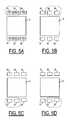
- FIG. 8Ais a cross-sectional side view showing a touch pad device having an LCD and a light guide on top of the LCD for touching.
- FIG. 8Bis a cross-sectional side view showing a touch pad device having an LCD and a thin cover on top of the LCD for touching.
- FIG. 8Cis a cross-sectional side view showing a touch pad device having an LCD and a curved cover on top of the LCD for touching.
- FIG. 8Dis a diagrammatic representation showing light transmission within the light guide in the touch pad device of FIG. 8 A.
- FIG. 9Ais a diagrammatic representation showing a touch pad device having one group of optical sensor components placed within the touch pad area.
- FIG. 9Bis a diagrammatic representation showing another touch pad device having one group of optical sensor components placed within the touch pad area.
- FIG. 9Cis a diagrammatic representation showing a touch pad device having two groups of optical sensor components placed within the touch pad area.
- FIG. 9Dis a diagrammatic representation showing another touch pad device having two groups of optical sensor components placed within the touch pad area.
- FIG. 9Eis a diagrammatic representation showing a touch pad device having four groups of optical sensor components placed within the touch pad area.
- FIG. 9Fis a diagrammatic representation showing a touch pad device having four light emitters and four light receivers placed within the touch pad area.
- FIG. 10Ais a diagrammatic representation showing the light output of a light emitter operated in a pulsed mode.
- FIG. 10Bis a diagrammatic representation showing the output signal of a receiver attributable to a light emitter operated in a pulsed mode.
- FIG. 10Cis a diagrammatic representation showing the output signal of a receiver attributable to a light emitter operated in a pulsed mode and ambient light.
- FIG. 10Dis a diagrammatic representation showing the light output of a compensation emitter.
- FIG. 10Eis a diagrammatic representation showing the output signal of a receiver attributable to a light emitter and a compensation emitter operated in a pulsed mode with complementary phases.
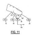
- FIG. 11is a diagrammatic representation showing the reflection of light emitted from two light emitters and a compensation emitter off a finger to reach a light receiver.
- FIG. 12Ais a diagrammatic representation showing a touch pad device having one group of optical sensor components operated in a pulsed mode including two light emitters, one compensation emitter and one light receiver.
- FIG. 12Bis a diagrammatic representation showing a touch pad device having two groups of optical sensor components operated in a pulsed mode placed near the touch pad area.
- FIG. 12Cis a diagrammatic representation showing a touch pad device having two groups of optical sensor components operated in a pulsed mode placed within the touch pad area.
- FIG. 13Ais a diagrammatic representation showing a touch pad device having four transceivers placing near the four edges of the touch pad area.
- FIG. 13Bis a diagrammatic representation showing a touch pad device having four transceivers placing near the four corners of the touch pad area.
- FIG. 13Cis a diagrammatic representation showing a touch pad device having four transceivers placing inside the four edges of the touch pad area.
- FIG. 13Dis a diagrammatic representation showing a touch pad device having four transceivers placing inside the four corners of the touch pad area.
- FIG. 14is a block diagram showing a system for detecting the presence of an object near the touch pad area of a touch pad device, according to the present invention.
- FIG. 15is a block diagram showing a mobile phone comprising a touch pad device, according to the present invention.
- two light emitters 10 , 20are positioned on opposite sides of a light receiver 30 in the proximity of a touch pad 5 (see FIGS. 2 A- 2 D).
- a touch pad 5see FIGS. 2 A- 2 D.
- some light 110 emitted from the emitter 10encounters the surface of the object 100 .
- Part of the light 110reflects off the object 100 and is received by the receiver 30 .
- some light 120 emitted from the emitter 20encounters the surface of the object 100 and then reflects off the object 100 to receiver 30 .
- the received portionsare denoted by reference numerals 112 and 122 .
- the amount of light received by the receiver 30can be measured from the output signal 130 . If the receiver 30 is not already saturated by ambient light, the presence of the object 100 near the emitters 10 , 20 and the receiver 30 would cause a change in the output signal 130 . When such a change is detected, it is preferred that the change attributable to the reflected light 112 and that attributable to the reflected light 122 are separately measured by turning off the emitter 20 and emitter 10 , respectively. As shown in FIG. 3A , the emitter 20 is turned off or disabled while the change in the received light amount 112 is measured. Likewise, the emitter 10 is turned off or disabled while the change in the received light amount 122 is measured, as shown in FIG. 3 B. In FIGS.
- the emitter and receiver involved in the measurementare enclosed by a dashed loop. From the changed amounts, it is usually possible to determine whether the object 100 is closer to the emitter 10 or the emitter 20 . In general, when the object 100 is closer to the emitter 10 than the emitter 20 , the output signal 130 responsive to the change in the received light amount 112 is larger than that in the received light amount 122 . With a series of such measurements, it is possible to track the positions of the object 100 and thus its movement.
- FIGS. 2A-2Dillustrate different arrangements of the light emitters 10 , 20 and the receiver 30 in a touch pad device 1 .
- the touch pad device 1has a “touch sensitive” area 5 surrounded by a peripheral area 3 . If the touch pad device 1 is a resistive-type device, for example, the surface of the “touch sensitive” area must be physically touched in order to change the resistance.
- the presence of the object 100 ′is detected by optical sensor components 10 , 20 and 30 . It is not necessary for the object 100 ′ to physically touch or press the area 5 at a touching point.
- the area 5can be considered as a designated interaction area where a user can use the object 100 ′ to interact with the touch pad device 1 in order to select the input functionality thereof.
- the phrase “touching the surface”, as used hereinafter regarding the touch pad device 1 of the present inventioncan be interpreted as “making contact with the surface” or “being adjacent to the surface”.
- the location of the “touching point”simply means the selected input location within the touch pad area 5 .
- the touch pad device 1can have a single input functionality or multiple input functionality.
- the touch pad device 1can be used as an “enter” key in a keyboard, as shown in FIG. 2B , or a toggle ON/OFF switch, as shown in FIG. 2 D. With one or more cycles of measurement, it is possible to detect the presence of an object intended for selecting the input functionality of the touch pad device 1 .
- the touch pad device 1as shown in FIG. 2A , can be used to select the “ON” function or “OFF” function, depending on the location of “touching” point on the touch pad area 5 .
- the user's finger 100 ′touches or approaches the pad area 5 , as shown in FIG. 2A , it is usually possible to determine from the changes in the output signal of the receiver 30 that the OFF function is selected.
- the sensor components 10 , 20 and 30are arranged in the peripheral area 3 near the bottom side of the touch area 5 .
- the sensor components 10 , 20 and 30can be arranged near the top side, left side and right side of the touch pad area 5 , as shown in FIGS. 2B , 2 C and 2 D, respectively.
- one or more functionscan be selected based on the location of the touching point along that direction in one dimension.
- the location of the touching point where the object is adjacent to the touch pad area 5can be determined if the reflection from the object surface does not vary significantly from one point to another.
- the touching objectis a pencil, as shown in FIG. 1
- different parts of the pencilmay reflect light differently.
- a larger amount of change in the received light in the receiver 30does not necessarily mean that the touching point is closer to one emitter or another. This means that the location of the touching point may not be accurately obtained.
- one group of sensor components 10 , 20 and 30is generally sufficient to sense the touching of the touch pad area 5 .
- two groups of three optical sensor elementsbe placed on opposite sides of the touch pad area 5 , as shown in FIGS. 4A and 4B .
- emitters 10 , 20 and receiver 30are placed near the top side of the touch pad area 5 .
- emitters 12 , 22 and receiver 32are placed near the bottom side of the touch pad area 5 .
- the touch pad device 1can have more than two functions arranged in two dimensions. For example, the user can select the “UP”, “DOWN”, “RIGHT” or “LEFT” function by touching at or near the respective arrow.
- the two groups of optical sensor elementscan be separately placed near the right and left sides of the touch pad area 5 , as shown in FIG. 4 B.
- the measurement result from the emitter 10 and receiver 30 pairis compared to the measurement result from the emitter 20 and receiver 30 ( FIG. 5B ) in order to determine the upper horizontal location of the touching point.
- the measurement result from the emitter 12 /receiver 32 pairis compared to the measurement result from the emitter 22 /receiver 32 pair ( FIG. 5D ) in order to determine the lower horizontal location of the touching point. From these four measurements (FIGS.
- the emitter 10 /receiver 32 pair(FIG. 5 E); the emitter 20 /receiver 32 pair (FIG. 5 F); the emitter 12 /receiver 30 pair (not shown) and the emitter 22 /receiver 30 pair (not shown).
- TX1 RXU TX2 TX3 RXD TX4measured direction 1 on on off off off off horizontal, upper 2 off on on off off off horizontal, upper 3 off off off on on off horizontal, lower 4 off off off off on on horizontal, lower 5 off on off on off off diagonal/ 6 off off on off on off diagonal/ 7 on off off off on off diagonal ⁇ 8 off on off off off off on diagonal ⁇
- the output from two emitterscan be combined in a single measurement.
- the measurement result from the emitters 10 , 22 and the receiver 30( FIG. 5G ) is compared to the measurement result from the emitters 12 , 20 and the receiver 30 (FIG. 5 H). This comparison is used to determine the horizontal location of the touching point.
- the measurement result from the emitters 10 , 22 and the receiver 32is compared to the measurement result from the emitters 12 , 20 and the receiver 32 in order to determined the horizontal location.
- FIG. 6 aFour groups of sensor components can be placed on four sides of the touch pad area 5 , as shown in FIG. 6 a . Similar to the measurements using the emitters 10 , 12 , 20 , 22 and receivers 30 , 32 , as shown in FIGS. 5A-5E and summarized in TABLE I, another series of eight measurements can be carried out with emitters 14 , 16 , 24 , 26 and receivers 34 , 36 . At any one time, only one emitter and one receiver are turned on for measurement. If it takes 1 ms to make one measurement cycle using one emitter/receiver combination, similar to the cycles shown in TABLE I, it requires 16 ms to make all such cycles.
- all the emitters 10 , 12 , 14 , 16 , 20 , 22 , 24 and 26are operated in a pulsed mode of a predetermined frequency.
- the emitters 10 , 20 , 12 and 22are operated in a phase complementary of the phase of the emitters 14 , 24 , 16 and 26 .
- a measurement of the horizontal positioncan be made simultaneously with a measurement of the vertical position in order to reduce the measurement time.
- the operating wavelength of the sensor components 14 , 16 , 24 , 26 , 34 and 36is different from the operating wavelength of the sensor components 10 , 12 , 20 , 22 , 30 and 32 .
- two measurements of different wavelengthscan be made simultaneously.
- the measurement taken with the emitter 10 and the receiver 30can be carried out simultaneously with the measurement taken with the emitter 14 and the receiver 34 .
- the measurement timecan be reduced in half.
- two emitters at each cornercan be replaced by a bi-wavelength emitter, as shown in FIG. 6 b .
- the emitters 10 and 14can be replaced by a bi-wavelength emitter 11 .
- bi-wavelength emitters 21 , 23 and 13are used to replace all other single-wavelength emitters.
- the touch pad area 5can be a display panel such as a liquid crystal display (LCD) 92 mounted on a printed circuit board (PCB) or a printed wire board (PWB) 90 .
- the optical sensor components 10 , 12 , 20 , 22 , 30 and 32are mounted in the peripheral area surrounding the LCD 92 .
- the touch pad device 1also includes a cover plate to provide a touch surface.
- a cover plate 60is placed on top of the LCD 92 and the optical sensor components (only emitters 10 and 12 are shown).
- the cover plate 60is designed as a light guide such that light emitted from the emitter 10 can reach the receiver 30 (see FIG.
- the light emitted from the emitter 12can be reach the receiver 32 (not shown) by way of total internal reflection, for example, when the touch pad device 1 is touched by or adjacent to the object 100 .
- the light ray 201 that reaches the receiver 30is by way of total internal reflection.
- the light rays 202 , 204reach the receiver 30 by way of partial reflection.
- the light rays 203 , 205could encounter the approaching finger and partially reflect off the finger toward the receiver 30 . Reflection causes the increase in the received light amount by the receiver 30 .
- both the increase and the decrease of the received light amount by the receiver 30indicate that touch pad device 1 is “touched”.
- the cover plate 70As shown in FIG. 8B , there is very little light from the emitters that reaches the receiver. The approaching and touching of the user's finger is detected by the reflection off the finger.
- the cover plate 80As shown in FIG. 8C , the amount of light emitted by the emitters 10 , 20 reaching the receiver could be more than that as shown in FIG. 8 B.
- the approaching and touching of the user's finger 100 ′is mainly detected by the reflection off the finger.
- all of the optical sensor componentsare placed outside the touch pad area 5 .
- the touch pad area 5can be used as a display to provide messages to the user or to indicate the functionality of the touch pad device 1 .
- the optical sensor componentscan also be placed inside the touch pad area 5 , as shown in FIGS. 9A-9F .
- FIGS. 9A and 9Bone group of optical sensor components, including two emitters 10 , 20 and one receiver 30 , is used to detect the location of the touching object and track the movement of thereof in one dimension. The measurements to be carried out using these emitters and receiver are similar to those illustrated in FIGS. 2A-3B .
- FIGS. 4A-5HThe arrangement of sensor components in FIG. 9E is similar to that illustrated in FIG. 6 A.
- the arrangement of sensor components in FIG. 9Fis similar to that illustrated in FIG. 6 B.
- the emitters 10 , 11 , 12 , 13 , 14 , 16 , 20 , 21 , 22 , 23 , 24 and 26can be operated in a continuous mode in that the output of the emitters does not contain a high frequency component, similar to the output of an incandescent lamp. Accordingly, the output signal 130 ( FIG. 1 ) of the receiver 30 is also constant or slow-varying. When the emitters are operated in a continuous mode, the output signal of the receiver can be significantly affected by ambient light. This means that the output signal of the receiver may vary from one location to another, regardless of whether the touching object is present at the touch pad device.
- the output variation due to ambient lightis significant, the detection and sensing of the presence of the touching object becomes difficult, if not impossible.
- these emittersbe operated in a pulsed mode such that the emitters are turned on and off at regular intervals at a selected frequency.
- the output intensity I E of a pulsed emitteris shown in FIG. 10 A.
- the output I R of the receiver attributable to the output intensity I E of the pulsed emitteris a series of pulses, as shown in FIG. 10B , when the receiver receives light from the pulsed emitter, regardless of whether the touching object is present at the touching pad device.
- the receiver and the emitterare in-phase with each other.
- the variation in the output signal of the receiver due to the variation in ambient lightis most likely a shift in the base line of the output signal, as shown in FIG. 10 C.
- the output variation due to ambient lightcan be easily removed using a high-pass filter, for example. Therefore, the variation in the pulsed output signal of the receiver is mainly the result of the reflection or absorption of the approaching object over the touch pad device.
- the output signal of the receiver 30 attributable to a pulsed emitter 10 arranged in a touch pad device, such as that illustrated in FIG. 8Dcan change if the upper surface 62 of the cover plate 60 is wet or dirty. Such a change could complicate the detection and sensing of the touching object.
- a compensation emitter 40adjacent to the receiver 30 , as shown in FIG. 11 .
- the phase of the compensation emitter 40is complementary to the phase of the emitters 10 , 20 .
- I Cdenotes the output intensity of the compensation emitter 40 .
- the compensation emitter 40is controlled such that when the touching object is not present, the output signal I E of the receiver 30 attributable to the emitters 10 , 20 is substantially equal to that attributable to the compensation emitter 40 .
- the output signal of the receiver 30does not contain a high frequency component, as shown in FIG. 10E , when the touching object is not present.
- the output signal of the receiver 30is substantially zero.
- the output signal of the receiver 30is substantially unaffected by the surface condition of the cover plate 60 .
- the use of a compensation emitterhas been disclosed in U.S. Pat. No. 5,666,037 entitled “Arrangement for measuring or detecting a change in a retro-reflective element” to Gerd Reime, and in EP 0 706 648 B1 of the same title to the same inventor.
- a compensation emitteris placed so as to balance out the output of the corresponding emitters (in a pulsed mode).
- the placement of the compensation emitteris similar to that shown in FIG. 11 .
- An exemplary arrangement of the compensation emitteris shown in FIGS. 12A-12C .
- a compensation emitter 40is placed adjacent to the receiver 30
- a compensation emitter 42is placed adjacent to the receiver 32 .
- the compensation emitter adjacent to the corresponding receiveris turned on or off together with that receiver. For example, in the measurement illustrated in FIG. 5E , the compensation emitter adjacent to the receiver 32 is turned on while the compensation emitter adjacent to the receiver 30 is turned off.
- the light emitters 10 , 12 , 14 , 16 , 20 , 22 , 24 and 26are light-emitting diodes (LEDs) operated in an infrared (IR) or far-IR frequency range.
- LEDslight-emitting diodes
- optical sensor componentsare dedicated components in that an emitter cannot be used as a receiver, and a receiver cannot be used as an emitter.
- optical transceiversin a touch pad device for detecting the presence of a touching object.
- FIGS. 13A-13Dfour transceivers A, B, C and D are arranged at the four edges or corners of the touch pad area 5 .
- Each of the transceivers A, B, C and Dcan be selectively used either as an emitter or a receiver, but not both.
- the combination of (I+II)yields a first horizontal position; the combination of (III+IV) yields a second horizontal position; (I+II) ⁇ ((III+IV) yields the vertical position; and (I+II)+(III+IV) yields the horizontal position.
- FIG. 14is a block diagram showing the basic components 400 in a system for detecting the presence of the touching object 100 and determining the location of the touching point on the touch pad area 5 , according to the present invention.
- a microprocessor or ASIC 460is connected to the components 400 to control the measurement on the touch pad device and make use of the measurement results therefrom.
- the touch pad deviceincludes a touch pad area 5 with two groups of sensor components separately placed at the top side and the bottom side of the touch pad area 5 , similar to FIG. 4 A.
- the emitters 10 , 12 , 20 , 22are connected to an enabling module 420 , which selectively enables or disables the emitters for measurements.
- the output signal 130 from the receiver 30 and the output signal 132 from the receiver 32are conveyed to a signal-processing module 450 .
- the enabling module 420 and the signal-processing module 450are under the control of a timing control module 430 .
- the timing control modulesends out a control signal 432 to the enabling module 420 for turning off or disabling the emitters 12 , 20 , 22 and enabling the emitter 10 .
- the timing control module 430sends out a control signal 434 to the signal processing module 450 such that only the output signal 132 from the receiver 32 is used.
- the signal processing module 450sends measurement information 452 to the microprocessor 460 .
- the microprocessor 460sends out a command signal 462 to the timing control 430 for starting the measurement of the next cycle.
- the microprocessor 460determines the location of the touching point. If the emitters 10 , 12 , 20 and 22 are operated in a pulsed mode of a predetermined frequency, then the signal-processing module 450 also comprises a filtering means to allow mainly the frequency component of the predetermined frequency in the output signal 130 and 132 to be measured.
- FIG. 15shows a portable electronic device, such as a mobile phone 500 that has a touch pad device of the present invention.
- the mobile phone 500includes the microprocessor 460 and the basic components 400 , as shown in FIG. 14 .
- the mobile phone 500comprises an antenna 504 connected to an RF module 506 for receiving and transmitting RF signals; a battery 508 , a microphone 512 , a speaker 514 and a keyboard 516 .
- the mobile phone 500may have a SIM card reader 508 and other electronic devices, such as display 518 .
- the additional components shown in FIG. 15are known in the art and not part of the present invention.
- FIG. 15is used to illustrate how a touch pad device can be used on an electronic device such as a mobile phone.
- the touch pad device 1has many applications.
- the touch pad device 1can be used as a key in a keyboard, as illustrated in FIG. 2B ; a switch with alternate functions, as illustrated in FIG. 2D ; and a control switch or device with two or more functions as illustrated in FIGS. 2A and 2C .
- the touch pad device 1as illustrated in FIG. 4A , can be used as a micro-mouse or a pointing device, for example.
- the usercan touch the touch pad area 5 at the designated locations to move the cursor up, down, left or right.
- the touch pad devicecan be used to track the movement of the touching object, it can be used to input information using the movement.
- a touch pad device with only one group of optical sensor componentscan detect the movement in one dimension.
- Such a touch pad devicecan be used as a volume control switch, for example, and the up/down motion or left/right motion of the touching object can be used to increase or decrease the volume of sound.
- the same devicecan be used as a light-dimming switch to allow a user to brighten or dim a light, or a zoom control switch to enlarge or reduce a displayed image on a screen.
- a touch pad device with two or more groups of optical sensor componentscan be used to track the movement of the touching device in two dimensions.
- Such a touch pad devicecan be used as a micro-mouse where the cursor can be moved in any direction on the screen following the movement of the touching object.
- the two-dimensional movement of the touching objectcan be linear, circular or irregular.
- a touch pad device with two or more groups of optical sensor componentscan be used as a virtual rotation knob, a virtual writing pad or a virtual drawing board.
- the touch pad areacan be round, elliptical, polygonal or of a irregular shape.
- the transmission and reflection of lightis for illustrative purposes only.
- the light rays shown in FIG. 11seem to obey specular reflection.
- a fingerhas a diffuse surface and light rays can penetrate into the skin.
- how light rays interact with the fingeris a complex matter.
- the present inventionprovides a method and device for detecting and sensing the presence of a touching object and the movement thereof in or near a touch pad area.
- the touch pad device 1as depicted in FIGS. 2A-13D , is used to provide a time-dependent signal based on a series of measurements.
- the scope of the present inventionincludes any applications and products that use the disclosed method and/or device using that time dependent signal.
- the time duration of the signal, the number of cycles in the series of measurements, and the time duration of each cycledepend on the applications and products.
- the output intensity, wavelength and other optical characteristics of the light emitters, the sensitivity and the optical response of the light receivers, and the optomechanical arrangement of these optical sensor components in a touch pad device, according to the present inventionmay vary from one application to another.
- the light emitters 10 , 20 , 12 and 22can be operated in a pulsed mode of the same frequency and the same phase.
- the light emitters 10 and 20are operated in a first phase and the light emitters 12 and 22 are operated in a second phase complementary of the first phase so that the measurement of cycle 1 (TABLE I) can be made simultaneously with the measurement of cycle 3 or cycle 4 , for example.
- the measurement of cycle 5can be made simultaneously with the measurement of cycle 6 .
- the measurement time for the entire 8 cyclescan be reduced in half.
- optical sensor componentsare solid state devices such as light-emitting diodes, optoelectronic sensors and transceivers operated at IR or far-IR frequencies.
- optical sensor components operated at other frequenciescan also be used.
Landscapes
- Engineering & Computer Science (AREA)
- General Engineering & Computer Science (AREA)
- Theoretical Computer Science (AREA)
- Human Computer Interaction (AREA)
- Physics & Mathematics (AREA)
- General Physics & Mathematics (AREA)
- Position Input By Displaying (AREA)
- Push-Button Switches (AREA)
- Blast Furnaces (AREA)
- Length Measuring Devices By Optical Means (AREA)
Abstract
Description
| TABLE I | ||||||||
| TX1 | RXU | TX2 | TX3 | RXD | TX4 | measured | ||
| 1 | on | on | off | off | off | off | horizontal, upper |
| 2 | off | on | on | off | off | off | horizontal, upper |
| 3 | off | off | off | on | on | off | horizontal, lower |
| 4 | off | off | off | off | on | on | horizontal, lower |
| 5 | off | on | off | on | off | off | diagonal/ |
| 6 | off | off | on | off | on | off | diagonal/ |
| 7 | on | off | off | off | on | off | diagonal\ |
| 8 | off | on | off | off | off | on | diagonal\ |
Claims (25)
Priority Applications (5)
| Application Number | Priority Date | Filing Date | Title |
|---|---|---|---|
| US09/928,967US6927384B2 (en) | 2001-08-13 | 2001-08-13 | Method and device for detecting touch pad unit |
| DE60231365TDE60231365D1 (en) | 2001-08-13 | 2002-07-25 | Method and device for detecting inputs at contact surfaces |
| EP02016636AEP1288848B1 (en) | 2001-08-13 | 2002-07-25 | Method and device for detecting touch pad input |
| AT02016636TATE424580T1 (en) | 2001-08-13 | 2002-07-25 | METHOD AND DEVICE FOR DETECTING INPUTS ON CONTACT SURFACES |
| CNB021285896ACN1257481C (en) | 2001-08-13 | 2002-08-13 | Method and device for inspecting input by contact pad |
Applications Claiming Priority (1)
| Application Number | Priority Date | Filing Date | Title |
|---|---|---|---|
| US09/928,967US6927384B2 (en) | 2001-08-13 | 2001-08-13 | Method and device for detecting touch pad unit |
Publications (2)
| Publication Number | Publication Date |
|---|---|
| US20030034439A1 US20030034439A1 (en) | 2003-02-20 |
| US6927384B2true US6927384B2 (en) | 2005-08-09 |
Family
ID=25457099
Family Applications (1)
| Application Number | Title | Priority Date | Filing Date |
|---|---|---|---|
| US09/928,967Expired - LifetimeUS6927384B2 (en) | 2001-08-13 | 2001-08-13 | Method and device for detecting touch pad unit |
Country Status (5)
| Country | Link |
|---|---|
| US (1) | US6927384B2 (en) |
| EP (1) | EP1288848B1 (en) |
| CN (1) | CN1257481C (en) |
| AT (1) | ATE424580T1 (en) |
| DE (1) | DE60231365D1 (en) |
Cited By (80)
| Publication number | Priority date | Publication date | Assignee | Title |
|---|---|---|---|---|
| US20050010315A1 (en)* | 2003-06-30 | 2005-01-13 | Silverman Martin S. | Entirely solid state audio device |
| US20050190162A1 (en)* | 2003-02-14 | 2005-09-01 | Next Holdings, Limited | Touch screen signal processing |
| US20050248540A1 (en)* | 2004-05-07 | 2005-11-10 | Next Holdings, Limited | Touch panel display system with illumination and detection provided from a single edge |
| US20060227120A1 (en)* | 2005-03-28 | 2006-10-12 | Adam Eikman | Photonic touch screen apparatus and method of use |
| US20060238490A1 (en)* | 2003-05-15 | 2006-10-26 | Qinetiq Limited | Non contact human-computer interface |
| US20070013550A1 (en)* | 2005-07-13 | 2007-01-18 | Tong Xie | Apparatus and method for integrating an optical navigation mechanism with non-optical sensor-based presence detector |
| US20070024598A1 (en)* | 2005-07-29 | 2007-02-01 | Miller Jeffrey N | Methods and systems for detecting selections on a touch screen display |
| US20070046646A1 (en)* | 2005-08-24 | 2007-03-01 | Lg Electronics Inc. | Mobile communications terminal having a touch input unit and controlling method thereof |
| US20070046637A1 (en)* | 2005-08-30 | 2007-03-01 | Lg Electronics Inc. | Touch key assembly for a mobile terminal |
| US20070105604A1 (en)* | 2005-08-30 | 2007-05-10 | Zhi-Min Choo | Mobile terminal with back-lighted directional keys |
| US20070103453A1 (en)* | 2005-08-30 | 2007-05-10 | Zhi-Min Choo | Touch key assembly for a mobile terminal |
| US20070279397A1 (en)* | 2006-05-30 | 2007-12-06 | Samsung Electronics Co., Ltd. | Fault-tolerant method, apparatus, and medium for touch sensor |
| US20080087797A1 (en)* | 2006-10-17 | 2008-04-17 | Turnbull Robert R | Optical user interface system for automotive modules |
| US20080191895A1 (en)* | 2005-06-22 | 2008-08-14 | Ralph Aschenbach | Microscope with a Display |
| US20100193259A1 (en)* | 2007-10-10 | 2010-08-05 | Ola Wassvik | Touch pad and a method of operating the touch pad |
| US20110063253A1 (en)* | 2009-09-17 | 2011-03-17 | Seiko Epson Corporation | Optical position detector and display device with position detection function |
| US20110062316A1 (en)* | 2009-09-17 | 2011-03-17 | Seiko Epson Corporation | Screen device with light receiving element and display device with position detection function |
| US20110089857A1 (en)* | 2008-06-10 | 2011-04-21 | Koninklijke Philips Electronics N.V. | Programmable user interface device for controlling an electrical power supplied to an electrical consumer |
| US20110096031A1 (en)* | 2009-10-26 | 2011-04-28 | Seiko Epson Corporation | Position detecting function-added projection display apparatus |
| US20110096032A1 (en)* | 2009-10-26 | 2011-04-28 | Seiko Epson Corporation | Optical position detecting device and display device with position detecting function |
| US20110109886A1 (en)* | 2009-11-06 | 2011-05-12 | Seiko Epson Corporation | Projection display device with position detection function |
| US20110134081A1 (en)* | 2009-12-09 | 2011-06-09 | Seiko Epson Corporation | Optical position detection device and display device with position detection function |
| US20110134080A1 (en)* | 2009-12-09 | 2011-06-09 | Seiko Epson Corporation | Optical position detection device and projection display device |
| US8055022B2 (en) | 2000-07-05 | 2011-11-08 | Smart Technologies Ulc | Passive touch system and method of detecting user input |
| US8089462B2 (en) | 2004-01-02 | 2012-01-03 | Smart Technologies Ulc | Pointer tracking across multiple overlapping coordinate input sub-regions defining a generally contiguous input region |
| US8094137B2 (en) | 2007-07-23 | 2012-01-10 | Smart Technologies Ulc | System and method of detecting contact on a display |
| US8115753B2 (en) | 2007-04-11 | 2012-02-14 | Next Holdings Limited | Touch screen system with hover and click input methods |
| US8120596B2 (en) | 2004-05-21 | 2012-02-21 | Smart Technologies Ulc | Tiled touch system |
| US20120120028A1 (en)* | 2010-11-11 | 2012-05-17 | Seiko Epson Corporation | Optical detection system and program |
| US8228304B2 (en) | 2002-11-15 | 2012-07-24 | Smart Technologies Ulc | Size/scale orientation determination of a pointer in a camera-based touch system |
| US8274496B2 (en) | 2004-04-29 | 2012-09-25 | Smart Technologies Ulc | Dual mode touch systems |
| US8325134B2 (en) | 2003-09-16 | 2012-12-04 | Smart Technologies Ulc | Gesture recognition method and touch system incorporating the same |
| US8339378B2 (en) | 2008-11-05 | 2012-12-25 | Smart Technologies Ulc | Interactive input system with multi-angle reflector |
| TWI382337B (en)* | 2007-11-30 | 2013-01-11 | Univ Lunghwa Sci & Technology | Touch screen system with light reflection |
| US8384693B2 (en) | 2007-08-30 | 2013-02-26 | Next Holdings Limited | Low profile touch panel systems |
| US8405636B2 (en) | 2008-01-07 | 2013-03-26 | Next Holdings Limited | Optical position sensing system and optical position sensor assembly |
| US8432377B2 (en)* | 2007-08-30 | 2013-04-30 | Next Holdings Limited | Optical touchscreen with improved illumination |
| US8456447B2 (en) | 2003-02-14 | 2013-06-04 | Next Holdings Limited | Touch screen signal processing |
| US8456418B2 (en) | 2003-10-09 | 2013-06-04 | Smart Technologies Ulc | Apparatus for determining the location of a pointer within a region of interest |
| US8456451B2 (en) | 2003-03-11 | 2013-06-04 | Smart Technologies Ulc | System and method for differentiating between pointers used to contact touch surface |
| US20130153747A1 (en)* | 2011-12-16 | 2013-06-20 | Samsung Electro-Mechanics Co., Ltd. | Input device |
| US20130176268A1 (en)* | 2012-01-09 | 2013-07-11 | Broadcom Corporation | Waterproof baseline tracking in capacitive touch controllers |
| US20130181613A1 (en)* | 2010-07-30 | 2013-07-18 | Mechaless Systems Gmbh | Opto-electronic measuring arrangement with electro-optical basic coupling |
| US8508508B2 (en) | 2003-02-14 | 2013-08-13 | Next Holdings Limited | Touch screen signal processing with single-point calibration |
| US8772703B2 (en) | 2011-03-14 | 2014-07-08 | Seiko Epson Corporation | Position detection system and projection display system |
| US8902193B2 (en) | 2008-05-09 | 2014-12-02 | Smart Technologies Ulc | Interactive input system and bezel therefor |
| US20150097029A1 (en)* | 2013-10-09 | 2015-04-09 | Castles Technology Co., Ltd. | Transactional Device Having Element for Identifying Wireless Sensing |
| US9046961B2 (en) | 2011-11-28 | 2015-06-02 | Corning Incorporated | Robust optical touch—screen systems and methods using a planar transparent sheet |
| US9158415B2 (en) | 2009-11-18 | 2015-10-13 | Lg Electronics Inc. | Touch panel, method for driving touch panel, and display apparatus having touch panel |
| US9213445B2 (en) | 2011-11-28 | 2015-12-15 | Corning Incorporated | Optical touch-screen systems and methods using a planar transparent sheet |
| US9223431B2 (en) | 2010-09-17 | 2015-12-29 | Blackberry Limited | Touch-sensitive display with depression detection and method |
| US20160154521A1 (en)* | 2013-12-26 | 2016-06-02 | Melfas Inc. | Touch sensing system and method for providing proximity sensing function using touch screen panel |
| US9442607B2 (en) | 2006-12-04 | 2016-09-13 | Smart Technologies Inc. | Interactive input system and method |
| US9513737B2 (en) | 2010-09-17 | 2016-12-06 | Blackberry Limited | Touch-sensitive display with optical sensor and method |
| US9874978B2 (en) | 2013-07-12 | 2018-01-23 | Flatfrog Laboratories Ab | Partial detect mode |
| US10019113B2 (en) | 2013-04-11 | 2018-07-10 | Flatfrog Laboratories Ab | Tomographic processing for touch detection |
| US10126882B2 (en) | 2014-01-16 | 2018-11-13 | Flatfrog Laboratories Ab | TIR-based optical touch systems of projection-type |
| US10146376B2 (en) | 2014-01-16 | 2018-12-04 | Flatfrog Laboratories Ab | Light coupling in TIR-based optical touch systems |
| US10161886B2 (en) | 2014-06-27 | 2018-12-25 | Flatfrog Laboratories Ab | Detection of surface contamination |
| US10168835B2 (en) | 2012-05-23 | 2019-01-01 | Flatfrog Laboratories Ab | Spatial resolution in touch displays |
| US10282035B2 (en) | 2016-12-07 | 2019-05-07 | Flatfrog Laboratories Ab | Touch device |
| US10318074B2 (en) | 2015-01-30 | 2019-06-11 | Flatfrog Laboratories Ab | Touch-sensing OLED display with tilted emitters |
| US10387710B2 (en)* | 2016-03-07 | 2019-08-20 | Microsoft Technology Licensing, Llc | Image sensing with a waveguide display |
| US10401546B2 (en) | 2015-03-02 | 2019-09-03 | Flatfrog Laboratories Ab | Optical component for light coupling |
| US10437389B2 (en) | 2017-03-28 | 2019-10-08 | Flatfrog Laboratories Ab | Touch sensing apparatus and method for assembly |
| US10474249B2 (en) | 2008-12-05 | 2019-11-12 | Flatfrog Laboratories Ab | Touch sensing apparatus and method of operating the same |
| US10481737B2 (en) | 2017-03-22 | 2019-11-19 | Flatfrog Laboratories Ab | Pen differentiation for touch display |
| US10496227B2 (en) | 2015-02-09 | 2019-12-03 | Flatfrog Laboratories Ab | Optical touch system comprising means for projecting and detecting light beams above and inside a transmissive panel |
| US10761657B2 (en) | 2016-11-24 | 2020-09-01 | Flatfrog Laboratories Ab | Automatic optimisation of touch signal |
| US11182023B2 (en) | 2015-01-28 | 2021-11-23 | Flatfrog Laboratories Ab | Dynamic touch quarantine frames |
| US11256371B2 (en) | 2017-09-01 | 2022-02-22 | Flatfrog Laboratories Ab | Optical component |
| US11301089B2 (en) | 2015-12-09 | 2022-04-12 | Flatfrog Laboratories Ab | Stylus identification |
| US11474644B2 (en) | 2017-02-06 | 2022-10-18 | Flatfrog Laboratories Ab | Optical coupling in touch-sensing systems |
| US11567610B2 (en) | 2018-03-05 | 2023-01-31 | Flatfrog Laboratories Ab | Detection line broadening |
| US11893189B2 (en) | 2020-02-10 | 2024-02-06 | Flatfrog Laboratories Ab | Touch-sensing apparatus |
| US11943563B2 (en) | 2019-01-25 | 2024-03-26 | FlatFrog Laboratories, AB | Videoconferencing terminal and method of operating the same |
| US12055969B2 (en) | 2018-10-20 | 2024-08-06 | Flatfrog Laboratories Ab | Frame for a touch-sensitive device and tool therefor |
| US12056316B2 (en) | 2019-11-25 | 2024-08-06 | Flatfrog Laboratories Ab | Touch-sensing apparatus |
| US12111988B1 (en) | 2023-09-19 | 2024-10-08 | Cirque Corporation | Illumination associated with a touch sensitive area |
| US12282653B2 (en) | 2020-02-08 | 2025-04-22 | Flatfrog Laboratories Ab | Touch apparatus with low latency interactions |
Families Citing this family (59)
| Publication number | Priority date | Publication date | Assignee | Title |
|---|---|---|---|---|
| US7461787B2 (en)* | 2000-11-20 | 2008-12-09 | Avante International Technology, Inc. | Electronic voting apparatus, system and method |
| DE10146996A1 (en)* | 2001-09-25 | 2003-04-30 | Gerd Reime | Circuit with an opto-electronic display content |
| US7077313B2 (en)* | 2001-10-01 | 2006-07-18 | Avante International Technology, Inc. | Electronic voting method for optically scanned ballot |
| US6987259B2 (en)* | 2002-05-30 | 2006-01-17 | Dmetrix, Inc. | Imaging system with an integrated source and detector array |
| US7952570B2 (en) | 2002-06-08 | 2011-05-31 | Power2B, Inc. | Computer navigation |
| KR100677321B1 (en)* | 2004-04-30 | 2007-02-02 | 엘지전자 주식회사 | Apparatus and method for controlling speaker volume in mobile communication terminal |
| DE102004054322B3 (en)* | 2004-11-10 | 2006-06-29 | Cherry Gmbh | Method and arrangement for setting on a service line |
| WO2006120182A1 (en) | 2005-05-10 | 2006-11-16 | Novo Nordisk A/S | Injection device comprising an optical sensor |
| US8610675B2 (en) | 2007-03-14 | 2013-12-17 | Power2B, Inc. | Interactive devices |
| US10452207B2 (en) | 2005-05-18 | 2019-10-22 | Power2B, Inc. | Displays and information input devices |
| JP4832826B2 (en)* | 2005-07-26 | 2011-12-07 | 任天堂株式会社 | Object control program and information processing apparatus |
| DE102005041309A1 (en)* | 2005-08-31 | 2007-03-15 | Siemens Ag | Operating unit for communication devices |
| JP2009508205A (en) | 2005-09-08 | 2009-02-26 | パワー2ビー,インコーポレイティド | Display and information input device |
| EP1929248B1 (en)* | 2005-09-22 | 2015-11-11 | Novo Nordisk A/S | Device and method for contact free absolute position determination |
| US8218154B2 (en)* | 2006-03-30 | 2012-07-10 | Flatfrog Laboratories Ab | System and a method of determining a position of a scattering/reflecting element on the surface of a radiation transmissive element |
| US8441467B2 (en)* | 2006-08-03 | 2013-05-14 | Perceptive Pixel Inc. | Multi-touch sensing display through frustrated total internal reflection |
| US20080029316A1 (en)* | 2006-08-07 | 2008-02-07 | Denny Jaeger | Method for detecting position of input devices on a screen using infrared light emission |
| US8106883B2 (en)* | 2006-10-10 | 2012-01-31 | Lg Electronics Inc. | Mobile terminal and method for moving a cursor and executing a menu function using a navigation key |
| WO2008073289A2 (en)* | 2006-12-08 | 2008-06-19 | Johnson Controls Technology Company | Display and user interface |
| KR20090030902A (en)* | 2007-09-21 | 2009-03-25 | 엘지전자 주식회사 | Input device of dishwasher and control method thereof, Input device of washing machine and control method thereof |
| US20090207144A1 (en)* | 2008-01-07 | 2009-08-20 | Next Holdings Limited | Position Sensing System With Edge Positioning Enhancement |
| US20090213093A1 (en)* | 2008-01-07 | 2009-08-27 | Next Holdings Limited | Optical position sensor using retroreflection |
| US8553014B2 (en) | 2008-06-19 | 2013-10-08 | Neonode Inc. | Optical touch screen systems using total internal reflection |
| US20110205189A1 (en)* | 2008-10-02 | 2011-08-25 | John David Newton | Stereo Optical Sensors for Resolving Multi-Touch in a Touch Detection System |
| CN102209949A (en)* | 2008-11-12 | 2011-10-05 | 平蛙实验室股份公司 | Integrated touch-sensing display apparatus and method of operating the same |
| KR101544475B1 (en)* | 2008-11-28 | 2015-08-13 | 엘지전자 주식회사 | I / O control through touch |
| US8643628B1 (en)* | 2012-10-14 | 2014-02-04 | Neonode Inc. | Light-based proximity detection system and user interface |
| US9158416B2 (en) | 2009-02-15 | 2015-10-13 | Neonode Inc. | Resilient light-based touch surface |
| JP4683135B2 (en)* | 2009-03-04 | 2011-05-11 | エプソンイメージングデバイス株式会社 | Display device with position detection function and electronic device |
| FI124221B (en) | 2009-04-24 | 2014-05-15 | Valtion Teknillinen | User input device and associated manufacturing method |
| US8928578B2 (en)* | 2009-04-29 | 2015-01-06 | Microsoft Corporation | Cursor adjustment in ambient light |
| US8542186B2 (en) | 2009-05-22 | 2013-09-24 | Motorola Mobility Llc | Mobile device with user interaction capability and method of operating same |
| US8294105B2 (en)* | 2009-05-22 | 2012-10-23 | Motorola Mobility Llc | Electronic device with sensing assembly and method for interpreting offset gestures |
| US8788676B2 (en)* | 2009-05-22 | 2014-07-22 | Motorola Mobility Llc | Method and system for controlling data transmission to or from a mobile device |
| US8692807B2 (en)* | 2009-09-02 | 2014-04-08 | Flatfrog Laboratories Ab | Touch surface with a compensated signal profile |
| SE534244C2 (en)* | 2009-09-02 | 2011-06-14 | Flatfrog Lab Ab | Touch sensitive system and method for functional control thereof |
| WO2011066343A2 (en)* | 2009-11-24 | 2011-06-03 | Next Holdings Limited | Methods and apparatus for gesture recognition mode control |
| US20110199387A1 (en)* | 2009-11-24 | 2011-08-18 | John David Newton | Activating Features on an Imaging Device Based on Manipulations |
| US8436833B2 (en)* | 2009-11-25 | 2013-05-07 | Corning Incorporated | Methods and apparatus for sensing touch events on a display |
| US20110205186A1 (en)* | 2009-12-04 | 2011-08-25 | John David Newton | Imaging Methods and Systems for Position Detection |
| JP2011177203A (en)* | 2010-02-26 | 2011-09-15 | Nintendo Co Ltd | Object controlling program and object controlling apparatus |
| US20110234542A1 (en)* | 2010-03-26 | 2011-09-29 | Paul Marson | Methods and Systems Utilizing Multiple Wavelengths for Position Detection |
| US8963845B2 (en) | 2010-05-05 | 2015-02-24 | Google Technology Holdings LLC | Mobile device with temperature sensing capability and method of operating same |
| US8751056B2 (en) | 2010-05-25 | 2014-06-10 | Motorola Mobility Llc | User computer device with temperature sensing capabilities and method of operating same |
| US9103732B2 (en) | 2010-05-25 | 2015-08-11 | Google Technology Holdings LLC | User computer device with temperature sensing capabilities and method of operating same |
| JP5533407B2 (en)* | 2010-08-04 | 2014-06-25 | セイコーエプソン株式会社 | Optical position detection device and device with position detection function |
| KR101816721B1 (en)* | 2011-01-18 | 2018-01-10 | 삼성전자주식회사 | Sensing Module, GUI Controlling Apparatus and Method thereof |
| US9164625B2 (en) | 2012-10-14 | 2015-10-20 | Neonode Inc. | Proximity sensor for determining two-dimensional coordinates of a proximal object |
| US9921661B2 (en) | 2012-10-14 | 2018-03-20 | Neonode Inc. | Optical proximity sensor and associated user interface |
| US10282034B2 (en) | 2012-10-14 | 2019-05-07 | Neonode Inc. | Touch sensitive curved and flexible displays |
| US10324565B2 (en) | 2013-05-30 | 2019-06-18 | Neonode Inc. | Optical proximity sensor |
| US10585530B2 (en) | 2014-09-23 | 2020-03-10 | Neonode Inc. | Optical proximity sensor |
| US9367177B2 (en)* | 2013-06-27 | 2016-06-14 | Hong Kong Applied Science and Technology Research Institute Company Limited | Method and system for determining true touch points on input touch panel using sensing modules |
| JP6327863B2 (en)* | 2014-01-10 | 2018-05-23 | 東京パーツ工業株式会社 | Motion sensor |
| US20170068392A1 (en)* | 2015-09-03 | 2017-03-09 | Ceebus Technologies, Llc | Touchscreen system usable in a variety of media |
| US11255663B2 (en) | 2016-03-04 | 2022-02-22 | May Patents Ltd. | Method and apparatus for cooperative usage of multiple distance meters |
| US11402950B2 (en)* | 2016-07-29 | 2022-08-02 | Apple Inc. | Methodology and application of acoustic touch detection |
| KR102797047B1 (en) | 2019-12-31 | 2025-04-21 | 네오노드, 인크. | Non-contact touch input system |
| TWI875394B (en)* | 2023-12-21 | 2025-03-01 | 致伸科技股份有限公司 | Touchpad module |
Citations (12)
| Publication number | Priority date | Publication date | Assignee | Title |
|---|---|---|---|---|
| US3673327A (en)* | 1970-11-02 | 1972-06-27 | Atomic Energy Commission | Touch actuable data input panel assembly |
| US4301447A (en) | 1979-12-12 | 1981-11-17 | Sperry Corporation | Scan control for light beam position indicator |
| US4311990A (en)* | 1978-11-16 | 1982-01-19 | Optical Techniques International, Inc. | Photo-optical keyboards |
| US4459476A (en)* | 1982-01-19 | 1984-07-10 | Zenith Radio Corporation | Co-ordinate detection system |
| US4710759A (en)* | 1984-02-22 | 1987-12-01 | Zenith Electronics Corporation | Interactive CRT with touch level set |
| US4893120A (en) | 1986-11-26 | 1990-01-09 | Digital Electronics Corporation | Touch panel using modulated light |
| EP0706648A1 (en) | 1993-07-02 | 1996-04-17 | Gerd Reime | Arrangement for measuring or detecting a change in a retro-reflective component |
| US5707160A (en) | 1992-08-24 | 1998-01-13 | Bowen; James H. | Infrared based computer input devices including keyboards and touch pads |
| US5726685A (en)* | 1994-06-30 | 1998-03-10 | Siemens Aktiengesellschaft | Input unit for a computer |
| WO2001069582A1 (en) | 2000-03-15 | 2001-09-20 | Touch Controls, Inc. | Photoelectric sensing array apparatus and method of using same |
| US6337918B1 (en)* | 1996-11-04 | 2002-01-08 | Compaq Computer Corporation | Computer system with integratable touchpad/security subsystem |
| US20020075243A1 (en) | 2000-06-19 | 2002-06-20 | John Newton | Touch panel display system |
- 2001
- 2001-08-13USUS09/928,967patent/US6927384B2/ennot_activeExpired - Lifetime
- 2002
- 2002-07-25DEDE60231365Tpatent/DE60231365D1/ennot_activeExpired - Lifetime
- 2002-07-25EPEP02016636Apatent/EP1288848B1/ennot_activeExpired - Lifetime
- 2002-07-25ATAT02016636Tpatent/ATE424580T1/ennot_activeIP Right Cessation
- 2002-08-13CNCNB021285896Apatent/CN1257481C/ennot_activeExpired - Fee Related
Patent Citations (13)
| Publication number | Priority date | Publication date | Assignee | Title |
|---|---|---|---|---|
| US3673327A (en)* | 1970-11-02 | 1972-06-27 | Atomic Energy Commission | Touch actuable data input panel assembly |
| US4311990A (en)* | 1978-11-16 | 1982-01-19 | Optical Techniques International, Inc. | Photo-optical keyboards |
| US4301447A (en) | 1979-12-12 | 1981-11-17 | Sperry Corporation | Scan control for light beam position indicator |
| US4459476A (en)* | 1982-01-19 | 1984-07-10 | Zenith Radio Corporation | Co-ordinate detection system |
| US4710759A (en)* | 1984-02-22 | 1987-12-01 | Zenith Electronics Corporation | Interactive CRT with touch level set |
| US4893120A (en) | 1986-11-26 | 1990-01-09 | Digital Electronics Corporation | Touch panel using modulated light |
| US5707160A (en) | 1992-08-24 | 1998-01-13 | Bowen; James H. | Infrared based computer input devices including keyboards and touch pads |
| EP0706648A1 (en) | 1993-07-02 | 1996-04-17 | Gerd Reime | Arrangement for measuring or detecting a change in a retro-reflective component |
| US5666037A (en) | 1993-07-02 | 1997-09-09 | Reime; Gerd | Arrangement for measuring or detecting a change in a retro-reflective element |
| US5726685A (en)* | 1994-06-30 | 1998-03-10 | Siemens Aktiengesellschaft | Input unit for a computer |
| US6337918B1 (en)* | 1996-11-04 | 2002-01-08 | Compaq Computer Corporation | Computer system with integratable touchpad/security subsystem |
| WO2001069582A1 (en) | 2000-03-15 | 2001-09-20 | Touch Controls, Inc. | Photoelectric sensing array apparatus and method of using same |
| US20020075243A1 (en) | 2000-06-19 | 2002-06-20 | John Newton | Touch panel display system |
Cited By (127)
| Publication number | Priority date | Publication date | Assignee | Title |
|---|---|---|---|---|
| US8378986B2 (en) | 2000-07-05 | 2013-02-19 | Smart Technologies Ulc | Passive touch system and method of detecting user input |
| US8055022B2 (en) | 2000-07-05 | 2011-11-08 | Smart Technologies Ulc | Passive touch system and method of detecting user input |
| US8203535B2 (en) | 2000-07-05 | 2012-06-19 | Smart Technologies Ulc | Passive touch system and method of detecting user input |
| US8228304B2 (en) | 2002-11-15 | 2012-07-24 | Smart Technologies Ulc | Size/scale orientation determination of a pointer in a camera-based touch system |
| US8456447B2 (en) | 2003-02-14 | 2013-06-04 | Next Holdings Limited | Touch screen signal processing |
| US8289299B2 (en) | 2003-02-14 | 2012-10-16 | Next Holdings Limited | Touch screen signal processing |
| US20050190162A1 (en)* | 2003-02-14 | 2005-09-01 | Next Holdings, Limited | Touch screen signal processing |
| US8508508B2 (en) | 2003-02-14 | 2013-08-13 | Next Holdings Limited | Touch screen signal processing with single-point calibration |
| US8466885B2 (en) | 2003-02-14 | 2013-06-18 | Next Holdings Limited | Touch screen signal processing |
| US7629967B2 (en) | 2003-02-14 | 2009-12-08 | Next Holdings Limited | Touch screen signal processing |
| US8456451B2 (en) | 2003-03-11 | 2013-06-04 | Smart Technologies Ulc | System and method for differentiating between pointers used to contact touch surface |
| US20060238490A1 (en)* | 2003-05-15 | 2006-10-26 | Qinetiq Limited | Non contact human-computer interface |
| US20050010315A1 (en)* | 2003-06-30 | 2005-01-13 | Silverman Martin S. | Entirely solid state audio device |
| US8325134B2 (en) | 2003-09-16 | 2012-12-04 | Smart Technologies Ulc | Gesture recognition method and touch system incorporating the same |
| US8456418B2 (en) | 2003-10-09 | 2013-06-04 | Smart Technologies Ulc | Apparatus for determining the location of a pointer within a region of interest |
| US8089462B2 (en) | 2004-01-02 | 2012-01-03 | Smart Technologies Ulc | Pointer tracking across multiple overlapping coordinate input sub-regions defining a generally contiguous input region |
| US8576172B2 (en) | 2004-01-02 | 2013-11-05 | Smart Technologies Ulc | Pointer tracking across multiple overlapping coordinate input sub-regions defining a generally contiguous input region |
| US8274496B2 (en) | 2004-04-29 | 2012-09-25 | Smart Technologies Ulc | Dual mode touch systems |
| US7538759B2 (en) | 2004-05-07 | 2009-05-26 | Next Holdings Limited | Touch panel display system with illumination and detection provided from a single edge |
| US20090122027A1 (en)* | 2004-05-07 | 2009-05-14 | John Newton | Touch Panel Display System with Illumination and Detection Provided from a Single Edge |
| US8149221B2 (en) | 2004-05-07 | 2012-04-03 | Next Holdings Limited | Touch panel display system with illumination and detection provided from a single edge |
| US20050248540A1 (en)* | 2004-05-07 | 2005-11-10 | Next Holdings, Limited | Touch panel display system with illumination and detection provided from a single edge |
| WO2005109396A3 (en)* | 2004-05-07 | 2006-12-14 | Next Holdings Ltd | Touch panel display system with illumination and detection provided from a single edge |
| US8120596B2 (en) | 2004-05-21 | 2012-02-21 | Smart Technologies Ulc | Tiled touch system |
| US7705835B2 (en) | 2005-03-28 | 2010-04-27 | Adam Eikman | Photonic touch screen apparatus and method of use |
| US20060227120A1 (en)* | 2005-03-28 | 2006-10-12 | Adam Eikman | Photonic touch screen apparatus and method of use |
| US20080191895A1 (en)* | 2005-06-22 | 2008-08-14 | Ralph Aschenbach | Microscope with a Display |
| US20070013550A1 (en)* | 2005-07-13 | 2007-01-18 | Tong Xie | Apparatus and method for integrating an optical navigation mechanism with non-optical sensor-based presence detector |
| US20070024598A1 (en)* | 2005-07-29 | 2007-02-01 | Miller Jeffrey N | Methods and systems for detecting selections on a touch screen display |
| US7629968B2 (en)* | 2005-07-29 | 2009-12-08 | Avago Technologies Fiber Ip (Singapore) Pte. Ltd. | Methods and systems for detecting selections on a touch screen display |
| US20070046646A1 (en)* | 2005-08-24 | 2007-03-01 | Lg Electronics Inc. | Mobile communications terminal having a touch input unit and controlling method thereof |
| US9244602B2 (en)* | 2005-08-24 | 2016-01-26 | Lg Electronics Inc. | Mobile communications terminal having a touch input unit and controlling method thereof |
| US7982718B2 (en)* | 2005-08-30 | 2011-07-19 | Lg Electronics Inc. | Mobile terminal with back-lighted directional keys |
| US20070046637A1 (en)* | 2005-08-30 | 2007-03-01 | Lg Electronics Inc. | Touch key assembly for a mobile terminal |
| US8049728B2 (en)* | 2005-08-30 | 2011-11-01 | Lg Electronics Inc. | Touch key assembly for a mobile terminal |
| US7825907B2 (en) | 2005-08-30 | 2010-11-02 | Lg Electronics Inc. | Touch key assembly for a mobile terminal |
| US20070105604A1 (en)* | 2005-08-30 | 2007-05-10 | Zhi-Min Choo | Mobile terminal with back-lighted directional keys |
| US20070103453A1 (en)* | 2005-08-30 | 2007-05-10 | Zhi-Min Choo | Touch key assembly for a mobile terminal |
| US7982719B2 (en)* | 2006-05-30 | 2011-07-19 | Samsung Electronics Co., Ltd. | Fault-tolerant method, apparatus, and medium for touch sensor |
| US20070279397A1 (en)* | 2006-05-30 | 2007-12-06 | Samsung Electronics Co., Ltd. | Fault-tolerant method, apparatus, and medium for touch sensor |
| US20080087797A1 (en)* | 2006-10-17 | 2008-04-17 | Turnbull Robert R | Optical user interface system for automotive modules |
| US7817020B2 (en)* | 2006-10-17 | 2010-10-19 | Gentex Corporation | Optical user interface system for automotive modules |
| WO2008048930A3 (en)* | 2006-10-17 | 2008-08-07 | Gentex Corp | Optical user interface system for automotive modules |
| US9442607B2 (en) | 2006-12-04 | 2016-09-13 | Smart Technologies Inc. | Interactive input system and method |
| US8115753B2 (en) | 2007-04-11 | 2012-02-14 | Next Holdings Limited | Touch screen system with hover and click input methods |
| US8094137B2 (en) | 2007-07-23 | 2012-01-10 | Smart Technologies Ulc | System and method of detecting contact on a display |
| US8432377B2 (en)* | 2007-08-30 | 2013-04-30 | Next Holdings Limited | Optical touchscreen with improved illumination |
| US8384693B2 (en) | 2007-08-30 | 2013-02-26 | Next Holdings Limited | Low profile touch panel systems |
| US8716614B2 (en) | 2007-10-10 | 2014-05-06 | Flatfrog Laboratories Ab | Touch pad and a method of operating the touch pad |
| US20100193259A1 (en)* | 2007-10-10 | 2010-08-05 | Ola Wassvik | Touch pad and a method of operating the touch pad |
| TWI382337B (en)* | 2007-11-30 | 2013-01-11 | Univ Lunghwa Sci & Technology | Touch screen system with light reflection |
| US8405636B2 (en) | 2008-01-07 | 2013-03-26 | Next Holdings Limited | Optical position sensing system and optical position sensor assembly |
| US8405637B2 (en) | 2008-01-07 | 2013-03-26 | Next Holdings Limited | Optical position sensing system and optical position sensor assembly with convex imaging window |
| US8902193B2 (en) | 2008-05-09 | 2014-12-02 | Smart Technologies Ulc | Interactive input system and bezel therefor |
| US20110089857A1 (en)* | 2008-06-10 | 2011-04-21 | Koninklijke Philips Electronics N.V. | Programmable user interface device for controlling an electrical power supplied to an electrical consumer |
| US8339378B2 (en) | 2008-11-05 | 2012-12-25 | Smart Technologies Ulc | Interactive input system with multi-angle reflector |
| US10474249B2 (en) | 2008-12-05 | 2019-11-12 | Flatfrog Laboratories Ab | Touch sensing apparatus and method of operating the same |
| US20110062316A1 (en)* | 2009-09-17 | 2011-03-17 | Seiko Epson Corporation | Screen device with light receiving element and display device with position detection function |
| US20110063253A1 (en)* | 2009-09-17 | 2011-03-17 | Seiko Epson Corporation | Optical position detector and display device with position detection function |
| US20110096031A1 (en)* | 2009-10-26 | 2011-04-28 | Seiko Epson Corporation | Position detecting function-added projection display apparatus |
| US9141235B2 (en) | 2009-10-26 | 2015-09-22 | Seiko Epson Corporation | Optical position detecting device and display device with position detecting function |
| US20110096032A1 (en)* | 2009-10-26 | 2011-04-28 | Seiko Epson Corporation | Optical position detecting device and display device with position detecting function |
| US9098137B2 (en) | 2009-10-26 | 2015-08-04 | Seiko Epson Corporation | Position detecting function-added projection display apparatus |
| US8348434B2 (en) | 2009-11-06 | 2013-01-08 | Seiko Epson Corporation | Projection display device with position detection function |
| US20110109886A1 (en)* | 2009-11-06 | 2011-05-12 | Seiko Epson Corporation | Projection display device with position detection function |
| US8714749B2 (en) | 2009-11-06 | 2014-05-06 | Seiko Epson Corporation | Projection display device with position detection function |
| US9158415B2 (en) | 2009-11-18 | 2015-10-13 | Lg Electronics Inc. | Touch panel, method for driving touch panel, and display apparatus having touch panel |
| US20110134081A1 (en)* | 2009-12-09 | 2011-06-09 | Seiko Epson Corporation | Optical position detection device and display device with position detection function |
| US8847918B2 (en) | 2009-12-09 | 2014-09-30 | Seiko Epson Corporation | Optical position detection device and display device with position detection function |
| US20110134080A1 (en)* | 2009-12-09 | 2011-06-09 | Seiko Epson Corporation | Optical position detection device and projection display device |
| US8766154B2 (en)* | 2010-07-30 | 2014-07-01 | Mechaless Systems Gmbh | Opto-electronic measuring arrangement with electro-optical basic coupling |
| US20130181613A1 (en)* | 2010-07-30 | 2013-07-18 | Mechaless Systems Gmbh | Opto-electronic measuring arrangement with electro-optical basic coupling |
| US9513737B2 (en) | 2010-09-17 | 2016-12-06 | Blackberry Limited | Touch-sensitive display with optical sensor and method |
| US9223431B2 (en) | 2010-09-17 | 2015-12-29 | Blackberry Limited | Touch-sensitive display with depression detection and method |
| US9041688B2 (en)* | 2010-11-11 | 2015-05-26 | Seiko Epson Corporation | Optical detection system and program |
| US20120120028A1 (en)* | 2010-11-11 | 2012-05-17 | Seiko Epson Corporation | Optical detection system and program |
| US8772703B2 (en) | 2011-03-14 | 2014-07-08 | Seiko Epson Corporation | Position detection system and projection display system |
| US9046961B2 (en) | 2011-11-28 | 2015-06-02 | Corning Incorporated | Robust optical touch—screen systems and methods using a planar transparent sheet |
| US9213445B2 (en) | 2011-11-28 | 2015-12-15 | Corning Incorporated | Optical touch-screen systems and methods using a planar transparent sheet |
| US20130153747A1 (en)* | 2011-12-16 | 2013-06-20 | Samsung Electro-Mechanics Co., Ltd. | Input device |
| US20130176268A1 (en)* | 2012-01-09 | 2013-07-11 | Broadcom Corporation | Waterproof baseline tracking in capacitive touch controllers |
| US8823678B2 (en)* | 2012-01-09 | 2014-09-02 | Broadcom Corporation | Waterproof baseline tracking in capacitive touch controllers |
| US10168835B2 (en) | 2012-05-23 | 2019-01-01 | Flatfrog Laboratories Ab | Spatial resolution in touch displays |
| US10019113B2 (en) | 2013-04-11 | 2018-07-10 | Flatfrog Laboratories Ab | Tomographic processing for touch detection |
| US9874978B2 (en) | 2013-07-12 | 2018-01-23 | Flatfrog Laboratories Ab | Partial detect mode |
| US20150097029A1 (en)* | 2013-10-09 | 2015-04-09 | Castles Technology Co., Ltd. | Transactional Device Having Element for Identifying Wireless Sensing |
| US20160154521A1 (en)* | 2013-12-26 | 2016-06-02 | Melfas Inc. | Touch sensing system and method for providing proximity sensing function using touch screen panel |
| US9778785B2 (en)* | 2013-12-26 | 2017-10-03 | Melfas Inc. | Touch sensing system and method for providing proximity sensing function using touch screen panel |
| US10146376B2 (en) | 2014-01-16 | 2018-12-04 | Flatfrog Laboratories Ab | Light coupling in TIR-based optical touch systems |
| US10126882B2 (en) | 2014-01-16 | 2018-11-13 | Flatfrog Laboratories Ab | TIR-based optical touch systems of projection-type |
| US10161886B2 (en) | 2014-06-27 | 2018-12-25 | Flatfrog Laboratories Ab | Detection of surface contamination |
| US11182023B2 (en) | 2015-01-28 | 2021-11-23 | Flatfrog Laboratories Ab | Dynamic touch quarantine frames |
| US10318074B2 (en) | 2015-01-30 | 2019-06-11 | Flatfrog Laboratories Ab | Touch-sensing OLED display with tilted emitters |
| US10496227B2 (en) | 2015-02-09 | 2019-12-03 | Flatfrog Laboratories Ab | Optical touch system comprising means for projecting and detecting light beams above and inside a transmissive panel |
| US11029783B2 (en) | 2015-02-09 | 2021-06-08 | Flatfrog Laboratories Ab | Optical touch system comprising means for projecting and detecting light beams above and inside a transmissive panel |
| US10401546B2 (en) | 2015-03-02 | 2019-09-03 | Flatfrog Laboratories Ab | Optical component for light coupling |
| US11301089B2 (en) | 2015-12-09 | 2022-04-12 | Flatfrog Laboratories Ab | Stylus identification |
| US10387710B2 (en)* | 2016-03-07 | 2019-08-20 | Microsoft Technology Licensing, Llc | Image sensing with a waveguide display |
| US10761657B2 (en) | 2016-11-24 | 2020-09-01 | Flatfrog Laboratories Ab | Automatic optimisation of touch signal |
| US11281335B2 (en) | 2016-12-07 | 2022-03-22 | Flatfrog Laboratories Ab | Touch device |
| US12189906B2 (en) | 2016-12-07 | 2025-01-07 | Flatfrog Laboratories Ab | Touch device |
| US10282035B2 (en) | 2016-12-07 | 2019-05-07 | Flatfrog Laboratories Ab | Touch device |
| US10775935B2 (en) | 2016-12-07 | 2020-09-15 | Flatfrog Laboratories Ab | Touch device |
| US11579731B2 (en) | 2016-12-07 | 2023-02-14 | Flatfrog Laboratories Ab | Touch device |
| US12175044B2 (en) | 2017-02-06 | 2024-12-24 | Flatfrog Laboratories Ab | Optical coupling in touch-sensing systems |
| US11474644B2 (en) | 2017-02-06 | 2022-10-18 | Flatfrog Laboratories Ab | Optical coupling in touch-sensing systems |
| US11740741B2 (en) | 2017-02-06 | 2023-08-29 | Flatfrog Laboratories Ab | Optical coupling in touch-sensing systems |
| US10606414B2 (en) | 2017-03-22 | 2020-03-31 | Flatfrog Laboratories Ab | Eraser for touch displays |
| US11099688B2 (en) | 2017-03-22 | 2021-08-24 | Flatfrog Laboratories Ab | Eraser for touch displays |
| US11016605B2 (en) | 2017-03-22 | 2021-05-25 | Flatfrog Laboratories Ab | Pen differentiation for touch displays |
| US10481737B2 (en) | 2017-03-22 | 2019-11-19 | Flatfrog Laboratories Ab | Pen differentiation for touch display |
| US11281338B2 (en) | 2017-03-28 | 2022-03-22 | Flatfrog Laboratories Ab | Touch sensing apparatus and method for assembly |
| US10739916B2 (en) | 2017-03-28 | 2020-08-11 | Flatfrog Laboratories Ab | Touch sensing apparatus and method for assembly |
| US11269460B2 (en) | 2017-03-28 | 2022-03-08 | Flatfrog Laboratories Ab | Touch sensing apparatus and method for assembly |
| US10845923B2 (en) | 2017-03-28 | 2020-11-24 | Flatfrog Laboratories Ab | Touch sensing apparatus and method for assembly |
| US10606416B2 (en) | 2017-03-28 | 2020-03-31 | Flatfrog Laboratories Ab | Touch sensing apparatus and method for assembly |
| US10437389B2 (en) | 2017-03-28 | 2019-10-08 | Flatfrog Laboratories Ab | Touch sensing apparatus and method for assembly |
| US11256371B2 (en) | 2017-09-01 | 2022-02-22 | Flatfrog Laboratories Ab | Optical component |
| US11650699B2 (en) | 2017-09-01 | 2023-05-16 | Flatfrog Laboratories Ab | Optical component |
| US12086362B2 (en) | 2017-09-01 | 2024-09-10 | Flatfrog Laboratories Ab | Optical component |
| US11567610B2 (en) | 2018-03-05 | 2023-01-31 | Flatfrog Laboratories Ab | Detection line broadening |
| US12055969B2 (en) | 2018-10-20 | 2024-08-06 | Flatfrog Laboratories Ab | Frame for a touch-sensitive device and tool therefor |
| US11943563B2 (en) | 2019-01-25 | 2024-03-26 | FlatFrog Laboratories, AB | Videoconferencing terminal and method of operating the same |
| US12056316B2 (en) | 2019-11-25 | 2024-08-06 | Flatfrog Laboratories Ab | Touch-sensing apparatus |
| US12282653B2 (en) | 2020-02-08 | 2025-04-22 | Flatfrog Laboratories Ab | Touch apparatus with low latency interactions |
| US11893189B2 (en) | 2020-02-10 | 2024-02-06 | Flatfrog Laboratories Ab | Touch-sensing apparatus |
| US12111988B1 (en) | 2023-09-19 | 2024-10-08 | Cirque Corporation | Illumination associated with a touch sensitive area |
Also Published As
| Publication number | Publication date |
|---|---|
| EP1288848A3 (en) | 2004-04-28 |
| ATE424580T1 (en) | 2009-03-15 |
| EP1288848B1 (en) | 2009-03-04 |
| US20030034439A1 (en) | 2003-02-20 |
| EP1288848A2 (en) | 2003-03-05 |
| CN1407506A (en) | 2003-04-02 |
| CN1257481C (en) | 2006-05-24 |
| DE60231365D1 (en) | 2009-04-16 |
Similar Documents
| Publication | Publication Date | Title |
|---|---|---|
| US6927384B2 (en) | Method and device for detecting touch pad unit | |
| US20030048257A1 (en) | Telephone set having a touch pad device | |
| JP7604760B2 (en) | Electronic devices equipped with a composite human interface | |
| US20250028401A1 (en) | Systems and apparatus for object detection using optical sensing | |
| US10042467B2 (en) | Integrated capacitive fingerprint sensor | |
| US6985137B2 (en) | Method for preventing unintended touch pad input due to accidental touching | |
| US11009990B2 (en) | Electronic device having multi-functional human interface | |
| US9285900B2 (en) | Touch pen using delay device and touch input method thereof and touch input system and method thereof | |
| US7784366B2 (en) | Single sided capacitive force sensor for electronic devices | |
| US20020061217A1 (en) | Electronic input device | |
| TWI444881B (en) | A touch device and a control method thereof, and an electronic device having the touch device | |
| WO1996032693A1 (en) | Position-determining input device and light emitting pen | |
| WO1996032693A9 (en) | Position-determining input device and light emitting pen | |
| KR101106278B1 (en) | Complex input device with touch function | |
| KR20190080997A (en) | Pen Input Device Supporting Heterogeneous Input Device | |
| KR101666490B1 (en) | Touchscreen device having conductive sensor | |
| KR20150085396A (en) | Complex-type input device with touch sensing features | |
| KR102171400B1 (en) | Electronic device having multi functional human interface and method for controlling the same | |
| US12271562B2 (en) | Multi-axis measurement with a capacitance module | |
| US10613692B2 (en) | Touch interactor | |
| EP1788790B1 (en) | Keyboard for mobile communication device | |
| KR20170065320A (en) | Method of controlling in cell type touch sensing display | |
| WO2015000116A1 (en) | Tapered mutual capacitive sensing pattern for single touch | |
| KR20150049106A (en) | Touch scrren device having double scan and method for touch sensing using the same |
Legal Events
| Date | Code | Title | Description |
|---|---|---|---|
| AS | Assignment | Owner name:NOKIA MOBILE PHONES LTD., FINLAND Free format text:ASSIGNMENT OF ASSIGNORS INTEREST;ASSIGNORS:REIME, GERD;KAIKURANTA, TERHO;REEL/FRAME:012423/0699 Effective date:20010828 | |
| STCF | Information on status: patent grant | Free format text:PATENTED CASE | |
| CC | Certificate of correction | ||
| FPAY | Fee payment | Year of fee payment:4 | |
| FPAY | Fee payment | Year of fee payment:8 | |
| AS | Assignment | Owner name:NOKIA TECHNOLOGIES OY, FINLAND Free format text:ASSIGNMENT OF ASSIGNORS INTEREST;ASSIGNOR:NOKIA CORPORATION;REEL/FRAME:036067/0222 Effective date:20150116 | |
| FPAY | Fee payment | Year of fee payment:12 | |
| AS | Assignment | Owner name:BP FUNDING TRUST, SERIES SPL-VI, NEW YORK Free format text:SECURITY INTEREST;ASSIGNOR:WSOU INVESTMENTS, LLC;REEL/FRAME:049235/0068 Effective date:20190516 | |
| AS | Assignment | Owner name:WSOU INVESTMENTS LLC, CALIFORNIA Free format text:ASSIGNMENT OF ASSIGNORS INTEREST;ASSIGNOR:NOKIA TECHNOLOGIES OY;REEL/FRAME:052694/0303 Effective date:20170822 | |
| AS | Assignment | Owner name:OT WSOU TERRIER HOLDINGS, LLC, CALIFORNIA Free format text:SECURITY INTEREST;ASSIGNOR:WSOU INVESTMENTS, LLC;REEL/FRAME:056990/0081 Effective date:20210528 | |
| AS | Assignment | Owner name:WSOU INVESTMENTS, LLC, CALIFORNIA Free format text:RELEASE BY SECURED PARTY;ASSIGNOR:TERRIER SSC, LLC;REEL/FRAME:056526/0093 Effective date:20210528 |