US6926758B2 - Electrostatic filter - Google Patents
Electrostatic filterDownload PDFInfo
- Publication number
- US6926758B2 US6926758B2US10/416,879US41687903AUS6926758B2US 6926758 B2US6926758 B2US 6926758B2US 41687903 AUS41687903 AUS 41687903AUS 6926758 B2US6926758 B2US 6926758B2
- Authority
- US
- United States
- Prior art keywords
- particles
- gas stream
- outlet
- gas
- charged
- Prior art date
- Legal status (The legal status is an assumption and is not a legal conclusion. Google has not performed a legal analysis and makes no representation as to the accuracy of the status listed.)
- Expired - Fee Related, expires
Links
Images


Classifications
- B—PERFORMING OPERATIONS; TRANSPORTING
- B03—SEPARATION OF SOLID MATERIALS USING LIQUIDS OR USING PNEUMATIC TABLES OR JIGS; MAGNETIC OR ELECTROSTATIC SEPARATION OF SOLID MATERIALS FROM SOLID MATERIALS OR FLUIDS; SEPARATION BY HIGH-VOLTAGE ELECTRIC FIELDS
- B03C—MAGNETIC OR ELECTROSTATIC SEPARATION OF SOLID MATERIALS FROM SOLID MATERIALS OR FLUIDS; SEPARATION BY HIGH-VOLTAGE ELECTRIC FIELDS
- B03C3/00—Separating dispersed particles from gases or vapour, e.g. air, by electrostatic effect
- B03C3/02—Plant or installations having external electricity supply
- B03C3/04—Plant or installations having external electricity supply dry type
- B03C3/14—Plant or installations having external electricity supply dry type characterised by the additional use of mechanical effects, e.g. gravity
- B03C3/15—Centrifugal forces
- B—PERFORMING OPERATIONS; TRANSPORTING
- B03—SEPARATION OF SOLID MATERIALS USING LIQUIDS OR USING PNEUMATIC TABLES OR JIGS; MAGNETIC OR ELECTROSTATIC SEPARATION OF SOLID MATERIALS FROM SOLID MATERIALS OR FLUIDS; SEPARATION BY HIGH-VOLTAGE ELECTRIC FIELDS
- B03C—MAGNETIC OR ELECTROSTATIC SEPARATION OF SOLID MATERIALS FROM SOLID MATERIALS OR FLUIDS; SEPARATION BY HIGH-VOLTAGE ELECTRIC FIELDS
- B03C3/00—Separating dispersed particles from gases or vapour, e.g. air, by electrostatic effect
- B03C3/02—Plant or installations having external electricity supply
- B03C3/04—Plant or installations having external electricity supply dry type
- B03C3/12—Plant or installations having external electricity supply dry type characterised by separation of ionising and collecting stations
- B—PERFORMING OPERATIONS; TRANSPORTING
- B03—SEPARATION OF SOLID MATERIALS USING LIQUIDS OR USING PNEUMATIC TABLES OR JIGS; MAGNETIC OR ELECTROSTATIC SEPARATION OF SOLID MATERIALS FROM SOLID MATERIALS OR FLUIDS; SEPARATION BY HIGH-VOLTAGE ELECTRIC FIELDS
- B03C—MAGNETIC OR ELECTROSTATIC SEPARATION OF SOLID MATERIALS FROM SOLID MATERIALS OR FLUIDS; SEPARATION BY HIGH-VOLTAGE ELECTRIC FIELDS
- B03C3/00—Separating dispersed particles from gases or vapour, e.g. air, by electrostatic effect
- B03C3/34—Constructional details or accessories or operation thereof
- B03C3/38—Particle charging or ionising stations, e.g. using electric discharge, radioactive radiation or flames
- B—PERFORMING OPERATIONS; TRANSPORTING
- B03—SEPARATION OF SOLID MATERIALS USING LIQUIDS OR USING PNEUMATIC TABLES OR JIGS; MAGNETIC OR ELECTROSTATIC SEPARATION OF SOLID MATERIALS FROM SOLID MATERIALS OR FLUIDS; SEPARATION BY HIGH-VOLTAGE ELECTRIC FIELDS
- B03C—MAGNETIC OR ELECTROSTATIC SEPARATION OF SOLID MATERIALS FROM SOLID MATERIALS OR FLUIDS; SEPARATION BY HIGH-VOLTAGE ELECTRIC FIELDS
- B03C3/00—Separating dispersed particles from gases or vapour, e.g. air, by electrostatic effect
- B03C3/34—Constructional details or accessories or operation thereof
- B03C3/40—Electrode constructions
- B03C3/41—Ionising-electrodes
- B—PERFORMING OPERATIONS; TRANSPORTING
- B03—SEPARATION OF SOLID MATERIALS USING LIQUIDS OR USING PNEUMATIC TABLES OR JIGS; MAGNETIC OR ELECTROSTATIC SEPARATION OF SOLID MATERIALS FROM SOLID MATERIALS OR FLUIDS; SEPARATION BY HIGH-VOLTAGE ELECTRIC FIELDS
- B03C—MAGNETIC OR ELECTROSTATIC SEPARATION OF SOLID MATERIALS FROM SOLID MATERIALS OR FLUIDS; SEPARATION BY HIGH-VOLTAGE ELECTRIC FIELDS
- B03C3/00—Separating dispersed particles from gases or vapour, e.g. air, by electrostatic effect
- B03C3/34—Constructional details or accessories or operation thereof
- B03C3/40—Electrode constructions
- B03C3/45—Collecting-electrodes
- B03C3/49—Collecting-electrodes tubular
- F—MECHANICAL ENGINEERING; LIGHTING; HEATING; WEAPONS; BLASTING
- F01—MACHINES OR ENGINES IN GENERAL; ENGINE PLANTS IN GENERAL; STEAM ENGINES
- F01N—GAS-FLOW SILENCERS OR EXHAUST APPARATUS FOR MACHINES OR ENGINES IN GENERAL; GAS-FLOW SILENCERS OR EXHAUST APPARATUS FOR INTERNAL-COMBUSTION ENGINES
- F01N3/00—Exhaust or silencing apparatus having means for purifying, rendering innocuous, or otherwise treating exhaust
- F01N3/01—Exhaust or silencing apparatus having means for purifying, rendering innocuous, or otherwise treating exhaust by means of electric or electrostatic separators
- B—PERFORMING OPERATIONS; TRANSPORTING
- B03—SEPARATION OF SOLID MATERIALS USING LIQUIDS OR USING PNEUMATIC TABLES OR JIGS; MAGNETIC OR ELECTROSTATIC SEPARATION OF SOLID MATERIALS FROM SOLID MATERIALS OR FLUIDS; SEPARATION BY HIGH-VOLTAGE ELECTRIC FIELDS
- B03C—MAGNETIC OR ELECTROSTATIC SEPARATION OF SOLID MATERIALS FROM SOLID MATERIALS OR FLUIDS; SEPARATION BY HIGH-VOLTAGE ELECTRIC FIELDS
- B03C2201/00—Details of magnetic or electrostatic separation
- B03C2201/10—Ionising electrode with two or more serrated ends or sides
- B—PERFORMING OPERATIONS; TRANSPORTING
- B03—SEPARATION OF SOLID MATERIALS USING LIQUIDS OR USING PNEUMATIC TABLES OR JIGS; MAGNETIC OR ELECTROSTATIC SEPARATION OF SOLID MATERIALS FROM SOLID MATERIALS OR FLUIDS; SEPARATION BY HIGH-VOLTAGE ELECTRIC FIELDS
- B03C—MAGNETIC OR ELECTROSTATIC SEPARATION OF SOLID MATERIALS FROM SOLID MATERIALS OR FLUIDS; SEPARATION BY HIGH-VOLTAGE ELECTRIC FIELDS
- B03C2201/00—Details of magnetic or electrostatic separation
- B03C2201/14—Details of magnetic or electrostatic separation the gas being moved electro-kinetically
- Y—GENERAL TAGGING OF NEW TECHNOLOGICAL DEVELOPMENTS; GENERAL TAGGING OF CROSS-SECTIONAL TECHNOLOGIES SPANNING OVER SEVERAL SECTIONS OF THE IPC; TECHNICAL SUBJECTS COVERED BY FORMER USPC CROSS-REFERENCE ART COLLECTIONS [XRACs] AND DIGESTS
- Y02—TECHNOLOGIES OR APPLICATIONS FOR MITIGATION OR ADAPTATION AGAINST CLIMATE CHANGE
- Y02T—CLIMATE CHANGE MITIGATION TECHNOLOGIES RELATED TO TRANSPORTATION
- Y02T10/00—Road transport of goods or passengers
- Y02T10/10—Internal combustion engine [ICE] based vehicles
- Y02T10/12—Improving ICE efficiencies
Definitions
- THIS INVENTIONrelates to an electrostatic filter suitable for separating (solid or liquid) particles from a gas stream.
- the inventionis particularly suitable for controlling air pollution from industrial processes, but is not limited to that particular application.
- the inventionmay also be used to filter particles from air supplied to air conditioning or ventilation systems, and to remove dust particles from airstreams in vacuum cleaning devices.
- the inventionmay also be used generally for separation of particles (solid or liquid) from a gas stream as a precursor to further processing of the gas stream, e.g. in recovery of fly ash and other fines in cement works.
- Stringent controlsare imposed by regulatory authorities on the emission of hazardous air pollutants, and these are likely to become even more stringent as pollution levels increase. Of particular concern are toxic trace metals and their compounds which exist in the form of small particles. Due to the nature of particulate formation in combustion processes, many of the trace metals, such as arsenic, cadmium, nickel and high-boiling point organic hazardous air pollutants, tend to concentrate on the fine, sub-micron sized particles present in flue gas.
- the known device typesinclude “scrubbers”, cyclonic separators and electrostatic filters. Examples of such devices can be found in U.S. Pat. Nos. 4,352,681; 4,478,613; 4,853,010; 5,591,253 and 6,017,381. Some installations may utilise two or more of such device types.
- the known devicesare generally suitable for removing larger particles from airstreams, they are usually much less effective in filtering out smaller particles, particularly sub-micron particles. However, it is the smaller particles which are the most problematic pollutants. Such small particles can be hazardous to health as they are easily absorbed through the lungs.
- the smaller micron and sub-micron particlesalso have a greater visual effect in polluted atmospheres. For the same total mass, smaller particles will generally be dispersed over a greater volume than larger particles, thereby increasing the volume of the polluted area. Further, the smaller particles cause “bending” or defraction of light, making the polluted air more visible.
- electrostatic filtersdust particles in a gas stream are charged by corona discharge or other ionic treatment, and the charged particles are electrostatically repelled from an aperture through which the “clean” air is removed. It is believed that one of the factors contributing to the relative inefficiency of known electrostatic filters is the short “treatment” time of the particles in the ionising stage.
- the corona-producing portion 11is a relatively short axial section which is traversed in a short period by the particles in the airstream. Consequently the particles, particularly the smaller particles, do not have sufficient time to be charged properly, and the electrostatic repulsion at the air take-off is less effective for such particles.
- the inventionprovides apparatus for separating particles from a gas stream, the apparatus comprising
- a housinghaving a chamber therein, and an inlet for introducing the gas stream into the chamber
- an ioniserin the housing for creating an ionising zone within the chamber through which the gas stream passes in use, particles in the gas stream being charged as they pass through the ionising zone, and
- a structure in the housingdefining an outlet for extracting gas from the chamber, the outlet being defined by one or more apertures in the structure which is operatively charged to the same polarity as the charged particles,
- outletis located downstream from the ionising zone, and in that the particles are moved away from the outlet as they pass through the ionising zone.
- the ioniseris typically an electrode array comprising multiple rows of electrodes distributed in the direction of travel of the gas stream.
- the electrodesare connected to a high voltage power supply, and generate a flow of ions to an earthed surface. This ionic “wind” carries or urges the particles in the gas stream to or towards the earthed surface, and away from the outlet(s).
- the particles in the gas streamspend at least 0.2 seconds in the ionising zone, and typically 0.2 second to 2.0 seconds.
- Each outlethas an electric field operatively associated with it to repel charged particles from the outlet.
- the structure defining the outlet(s)is connected to the same high voltage source as the electrode array of the ioniser.
- the outlet aperturesare preferably located at least as far from the earthed surface as the electrode array.
- a dust collection hopper or containeris suitably located beneath the earthed surface to collect dust and other particles removed from the gas stream which is extracted from the outlet(s).
- the gas streamsmay be fed to, and extracted from, the housing via plenum-like spaces.
- the outletsare orientated so that the particles must change direction in order to pass through the outlets.
- the apparatusmay comprise a series of ionisers spaced in the direction of flow of the gas stream, each ioniser being followed by one or more outlets. In this manner, the gas stream is progressively “cleaned”.
- the inventionprovides a method of separating particles from a gas stream, including the steps of:
- outletis located downstream and separate from the ionising zone and in that the particles are moved away from the outlet as they pass through the ionising zone.
- the ionic “wind” created by the ioniserurges the particles away from the outlet(s).
- An electric field associated with the outletrepels the charged particles, so that “clean” gas is extracted through the outlet.
- FIG. 1is a vertical sectional schematic view of an electrostatic filter according to one embodiment of the invention
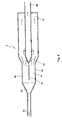
- FIG. 2is a vertical sectional schematic view of an electrostatic filter according to a second embodiment of the invention.
- FIGS. 3 and 4are sectional schematic views of further embodiments of the electrostatic filter of this invention.
- the electrostatic filter of FIG. 1comprises a housing 1 having a cylindrical wall 10 defining a chamber 11 . At least the inside surface of the wall 10 is a conductive earthed surface.
- the housinghas an inlet 12 adapted to receive “dirty” gas containing dust particles and other pollutants.
- the bottom of housing 10is tapered to form a collection hopper 14 which receives dust particles and other pollutants removed from the inlet gas as described below.
- the hopper 14communicates with an outlet 15 for discharging the collected dust particles as well as water which may be used to wash down the wall 10 .
- the filteralso has an outlet 13 for “clean” gas from which the dust particles and pollutants have been removed.
- the wall 10is typically circular in cross section, and the inlet 12 may be located tangentially to the housing so that the inlet gas enters the chamber 11 in a swirling action.
- Water sprays 8may be used at the inlet to enhance dust removal and cool the incoming gas.
- the “dirty” gas at the inletis typically flue gas from combustion or other industrial processes.
- the inlet gasmay alternatively be vehicle exhaust gas, a vacuum cleaner airstream to be cleaned, or atmospheric air for filtering prior to use in air conditioning or other ventilation systems.
- the inlet gastypically contains particles of dust and other pollutants which may be as small as 0.1 micrometre ( ⁇ m) in diameter. Fine particles, less than 5 ⁇ m in diameter, have been extremely difficult to remove from gas streams, and are a major health hazard due to their high potential toxicity and ease of respiration.
- the dirty inlet gasmay contain dust burdens as high as 1000 gms/m 3 , although levels of 10 gms/m 3 are most common.
- An electrically insulating tube 16is mounted centrally and axially within the chamber 11 as shown in the drawing.
- the insulating tube 16may suitably be constructed from plastic or epoxy material for low temperature applications, or from ceramic material for high temperature applications.
- the upper end of the tube 16communicates with a conduit 17 which provides the outlet 13 for the clean gas.
- a gas flow distributor 18is suitably mounted on the tube 16 .
- the distributor 18is a baffle-like radial plate with a part-conical upper surface.
- the distributor 18is dimensionally smaller than the cylindrical wall 10 so that an annular gap or clearance is provided between the distributor 18 and the wall 10 .
- a plenum-type chamberis formed above the distributor 18 , from which the dirty inlet gas is distributed evenly around the outside of the chamber 11 , relying on a small pressure drop across the annular gap or clearance to distribute the gas flow around the outside of an electrostatic chamber formed below the distributor (as illustrated by the arrows).
- the gas distributionmay be assisted by the cyclone effect generated by the tangential mounting of the inlet 12 to the cylindrical housing 1 , although a cyclonic action is not necessarily required, particularly for small particle separation. This cyclone effect will urge the heavier dust particles towards the outer cylindrical wall 10 of the housing 1 .
- An ion generator 19is mounted on the central axial tube 16 in the electrostatic chamber, below the distributor 18 . Due to the insulative properties of the tube 16 , the ion generator 19 is electrically insulated from the outlet conduit 17 and the other components of the housing.
- the ion generator 19is a hollow metal tube having radial electrodes 20 on its outside which have sharp points at their distal ends. Each electrode 20 may be in the form of a prong or barb formed from a single strand wire or multiple strands of wire of small diameter.
- the electrodes 20are arranged in axially spaced rows distributed over the ioniser 19 .
- the distance between the electrodes 20 of the ion generator 19 and the outer cylindrical wall of housing 10is typically 100 mm to 1000 mm, depending on the application for which the electrostatic filter is designed.
- the ion generator 19is connected to a high voltage source.
- the voltagemust be high enough to create corona at the electrode ends.
- the voltageis usually a minimum of 1 kV, and more typically 20 kV to 50 kV. (For clarity, the voltage source and the wire(s) connecting the ion generator to the voltage source are omitted from the drawing).
- the high voltage at the sharp points of the electrodes 20creates a strong electric field around each sharp point which, in turn, produces intense corona at those points.
- the intense corona generated at the sharp point of each of the electrodes 20produces a concentrated flow of ions from the ion generator 19 to the wall 10 of the housing 1 which is earthed.
- the use of such electric fields around sharp extremities to create corona discharge and ion flowis known in the art and need not be described in detail in this application.
- the ion generator 19therefore produces an ionising zone in which an ionic or electrostatic “wind” flows from the ion generator 19 to the earthed cylindrical wall 10 , generally perpendicular to the flow of gas from the distributor 18 .
- This ionic windcarries or urges the dust particles in the dirty gas to the internal surface of the cylindrical housing wall 10 .
- the ions in the electrostatic “wind”transfer their charge to dust particles which they encounter in the gas stream, causing the dust particles to be charged to the same polarity as the electrodes 20 of the ion generator 19 .
- the charge applied to the particleswill cause the particles to be repelled from the high voltage electrode array 20 and to be attracted to the earthed wall 10 of the housing.
- the particlesare therefore moved to the wall by a combination of kinetic and electrical forces.
- the axial length of the ion generator 19is selected so that the time taken for the gas to pass by the ion generator (“the treatment time”) is sufficient to allow the dust particles to be moved out to the cylindrical wall by the ionic “wind”. Under intense ion bombardment, the dust particles will charge very rapidly and achieve saturation charge in a fraction of a second. However, the treatment time should be long enough to allow even the smaller particles to be charged and moved out to the wall 10 .
- the treatment timei.e. the time for which the gas is subject to the ionic “wind” from the electrode array, is at least 0.2 sec, and more preferably between 0.2 sec and 2 sec. Depending on the gas speed, this may typically require the electrode array of the ion generator 19 to be 0.2 m to 2 m long (in the axial direction), containing 5 to 50 axially-spaced rows of electrodes 20 .
- the ion generatormay be constructed to permit its length to be adjusted manually or automatically to optimise the period of time which the particles spend in the ionising zone, e.g. by using a telescoping construction for the ion generator.
- Dust particles in the air which attach to the wall 10are scoured off and carried to the dust collection hopper 14 by the gas flow and gravity. In the case of highly resistive dust which is difficult to detach from the wall surface, it may be necessary to wash the wall 10 with water using overhead water sprays.
- a gas outlet or take-off 21is located below the ion generator 19 .
- the gas take-off 21is preferably located as far from the earthed wall 10 as the electrode array 20 .
- the gas take-off 21comprises a plurality of stacked vanes 22 which define annular spaces between them (hereafter referred to as the “vane apertures”).
- the vane aperturescommunicate with the outlet conduit 17 via the hollow interior of the ion generator 19 and the insulating tube 16 .
- the vanes 22are metal vanes which are electrically connected to the ion generator 19 so that they are also maintained at the same high voltage as the ion generator.
- the high voltage applied to the vanes 22creates intense electrical fields around the outer circular edges of the vanes. These electric fields extend across the vane apertures and will repel charged particles due to the large electrostatic forces developed by this configuration. Hence, the electrostatic fields at the vane apertures will prevent the dust particles which have been charged by passage through the ionic “wind” from entering the vane apertures.
- the particlesare required to change their direction of movement in order to pass out of the vane apertures.
- the inertia of the particles in the downward directioncoupled with gravity, also helps prevent the dust particles exiting through the vane apertures with the “clean” gas.
- the dust particles which are repelled from the vane aperturesfall into the dust collection hopper 14 at the bottom of the housing as a result of gravity and the overall downward gas flow.
- the collected dustis removed from the hopper 14 through the dust outlet extraction pipe 15 .
- Thismay suitably be achieved using a venturi water suction system or through dry dust extraction using a dust slide or pneumatic conveying system.
- the hopper 14may be removable.
- the “clean” gas extracted through the vane apertures 22passes through a plenum-like space formed by the hollow tubular interior of the ion generator 19 , the insulated tube 16 and the outlet conduit 17 , before exiting from the clean gas outlet 13 .
- “dirty” gasis introduced into inlet 12 . Due to the operation of the gas flow distributor 18 and the cyclone effect on the swirling inlet flow, larger particles of dust and other contaminants in the inlet gas are moved towards the outside cylindrical wall 10 of the housing. As the gas flows axially down the chamber 11 past the ion generator 19 , the ionic “wind” charges the particles in the gas stream, causing them to be repelled away from the ion generator 19 and attracted to the earthed outer wall 10 . Clean gas (typically air) is extracted via the vane apertures.
- the dust particles and other contaminantsare collected in the hopper 14 by using the gas flow along the cylindrical wall 10 to scour the particles from the wall, using water sprays to wash down the wall 10 , and/or utilising gravity and particle momentum in the low flow region below the vane take-off.
- the tangential positioning of the inlet 12promotes a cyclonic effect, such an effect is not required and the flow of gas through the chamber may be predominantly linear or axial as shown in other embodiments herein.
- the electrostatic filter of the embodiment of FIG. 2has a housing 2 formed by a wall 23 of generally circular cross section and whose diameter increased progressively in the direction of gas flow (indicated by the arrows).
- Multiple tubular electrode assemblies 24are located centrally within the chamber formed by the wall 23 .
- Gas outlets or take-offs 25are provided between each electrode array 24 .
- Each gas take-off 25is in the form of one or more apertures in the bottom of each electrode array. These apertures communicate with the hollow interior of the electrode arrays 24 which, in turn, communicate with an outlet 26 via an insulating tube 27 to which the electrode arrays 24 are mounted.
- the inlet gas flowing in the direction shown in FIG. 2is progressively treated by the successive electrode arrays 24 , with a portion of the “clean” gas being extracted through each successive take-off aperture.
- the design of the successive electrode arraysmay be varied to take advantage of the changing gas conditions with, for example, the characteristics of the electrodes or the clearance between the electrodes and the earthed wall 23 varying in the successive electrode arrays as the gas becomes cleaner.
- the earthed wall 23may comprise portions which are parallel to, or equidistant from, the electrode arrays, as well as portions which are angled away from the electrode array so that the distance between the electrodes and the earth wall varies.
- the earthed wall 23may be augmented by internal walls or vanes 28 which better trap dust particles urged radially outwardly by the ionic wind, and then direct the dust particles to a collection hopper 29 at the base of the housing 2 .
- the electrode array and outlet aperturesmay be located in a planar member opposed to an earthed planar surface and coupled thereto by insulating walls to form a duct or passage for the inlet gas.
- FIG. 3illustrates a third embodiment of the invention.
- the electrostatic filter 3 of FIG. 3has a housing 30 defining a passage 31 for a gas stream.
- the passagecommunicates with an inlet 32 via the hollow interior of an insulating portion 34 .
- a water spray 33may suitably be provided at the inlet 32 .
- the electrostatic filter 3also has a series of successive ion generators 35 , with air take-off apertures 36 located after respective ion generators 35 .
- Each ion generator 35comprises a series of electrodes spaced in the direction of travel of the gas stream.
- the apertures 36communicate with an outlet 38 .
- a hopper for collecting dust and other particles extracted from the air streamis provided at the bottom of the housing 30 .
- High voltage components of the electrostatic filterare electrically insulated from other components of the filter by suitable insulative portions 39 , 34 .
- “dirty” gas entering inlet 32is washed by the water sprays 33 before entering the chamber 31 via the plenum-like chamber formed in hollow insulating portion 34 .
- the particles in the gas streamare charged by the ions travelling from the electrodes of the ion generator to the earthed wall opposite. The particles are thereby carried by the ionic “wind” to the opposite wall and “clean” gas is extracted through the outlets 36 .
- the components defining the outlets 36are also charged to a high voltage. This high voltage generates intense electric fields around the apertures 36 , repelling charged dust particles from the apertures.
- the “clean” gaspasses from the apertures 36 to the outlet 38 while particles “trapped” within the electrostatic filter travel down the inclined wall 30 and are collected in hopper 37 .
- the design of successive ion generators 35 and apertures 36may be varied, to take into account that the gas becomes progressively “cleaner”.
- an electrostatic filter 4comprises a square section housing 40 defining a chamber 41 therein.
- the chamber 41receives “dirty” gas from an inlet 42 , via a plenum section 43 .
- the chamber 41has a series of axially-spaced electrodes 44 . That is, the electrodes 44 are distributed along the direction of travel of the gas.
- the electrodes 44generate ions which travel transversely to the gas flow to the opposite earthed walls of housing 40 . The particles in the gas flow are charged by these ions, and are carried or urged towards the earthed walls of the housing 40 .
- Multiple apertures 45are provided downstream of the ionising electrodes 44 . These apertures may be suitably located behind vane-like formations, so that the particles in the gas stream must change direction in order to exit via the apertures. Clean gas is extracted via the apertures 45 and fed to an outlet 46 . The particles extracted from the gas are collected in a hopper 47 . As with the previous embodiments, the structure defining the apertures 45 may be charged to create electric fields across the apertures to repel charged particles.
- the “clean” gas extracted from a single filtermay still contain some contaminant particles.
- Multiple electrostatic filtersmay therefore be placed in series to treat the gas successively, with the “clean” gas extracted from one electrostatic filter being fed to the inlet of the next successive filter.
- the electrostatic filters in the seriesmay have different internal arrangements to take advantage of the fact that the gas will be cleaner at each successive stage, and can therefore be designed to enhance fine particle removal.
- the outlet aperturesmay be directed away from the inlet gas flow to create centrifugal forces, and the electrode array spaced further from the earthed surface to better collect larger dust particles, whereas in the second or later stage filters, the outlet apertures may be directed towards the inlet gas flow to obtain non-turbulent flow, and the spacing between the electrode array and the earthed surface decreased since the propensity of the electrodes to spark or arc will be reduced by the earlier removal of the large particles.
- a “dirty” gas streammay be divided and fed to several electrostatic filters connected in parallel.
- the flow through the aperturescan be adjusted by varying the size, location and/or orientation of the outlet apertures.
- rotary valvesmay be placed in the apertures 25 to enable the gas flow through each aperture to be adjusted.
- FIGS. 1 and 2illustrate the electrode array and air take-off(s) being mounted on a tube located centrally within a generally cylindrical housing
- the configurationmay be reversed. That is, the electrodes and gas take-off(s) may be located on an outer wall, with the earthed surface being provided by an axial rod or tube located within the housing.
- the gas flow distributoris suitably modified to direct the gas flow along the earthed rod or tube.
- the distributormay be shaped and/or configured to distribute the gas flow in the vicinity of the electrode array.
- housing wallsof generally circular cross-sectional shape
- other suitable shapes and configurationsmay be used, as would be evident to a person skilled in the art.
Landscapes
- Engineering & Computer Science (AREA)
- Chemical & Material Sciences (AREA)
- Combustion & Propulsion (AREA)
- Mechanical Engineering (AREA)
- General Engineering & Computer Science (AREA)
- Electrostatic Separation (AREA)
Abstract
Description
Claims (10)
Applications Claiming Priority (3)
| Application Number | Priority Date | Filing Date | Title |
|---|---|---|---|
| AUPR1605AAUPR160500A0 (en) | 2000-11-21 | 2000-11-21 | Electrostatic filter |
| AUPR1605 | 2000-11-21 | ||
| PCT/AU2001/001501WO2002042003A1 (en) | 2000-11-21 | 2001-11-20 | Electrostatic filter |
Publications (2)
| Publication Number | Publication Date |
|---|---|
| US20040025497A1 US20040025497A1 (en) | 2004-02-12 |
| US6926758B2true US6926758B2 (en) | 2005-08-09 |
Family
ID=3825645
Family Applications (1)
| Application Number | Title | Priority Date | Filing Date |
|---|---|---|---|
| US10/416,879Expired - Fee RelatedUS6926758B2 (en) | 2000-11-21 | 2001-11-20 | Electrostatic filter |
Country Status (5)
| Country | Link |
|---|---|
| US (1) | US6926758B2 (en) |
| EP (1) | EP1343590A4 (en) |
| CN (1) | CN1261226C (en) |
| AU (1) | AUPR160500A0 (en) |
| WO (1) | WO2002042003A1 (en) |
Cited By (14)
| Publication number | Priority date | Publication date | Assignee | Title |
|---|---|---|---|---|
| US20040255784A1 (en)* | 2001-11-30 | 2004-12-23 | Harry Johansson | Discharge electrode |
| US20060250746A1 (en)* | 2005-05-06 | 2006-11-09 | Cool Shield, Inc. | Ionic flow generator for thermal management |
| US20080060522A1 (en)* | 2006-09-13 | 2008-03-13 | United Technologies Corporation | Electrostatic particulate separation system and device |
| US20080250926A1 (en)* | 2007-04-10 | 2008-10-16 | Yefim Riskin | Method of air purification from dust and electrostatic filter |
| US7465338B2 (en) | 2005-07-28 | 2008-12-16 | Kurasek Christian F | Electrostatic air-purifying window screen |
| US7537647B2 (en)* | 2005-08-10 | 2009-05-26 | S.C. Johnson & Son, Inc. | Air purifier |
| US20090151567A1 (en)* | 2007-12-17 | 2009-06-18 | Henry Krigmont | Space efficient hybrid air purifier |
| US20090151568A1 (en)* | 2007-12-17 | 2009-06-18 | Krigmont Henry V | Space efficient hybrid collector |
| US7559976B2 (en)* | 2006-10-24 | 2009-07-14 | Henry Krigmont | Multi-stage collector for multi-pollutant control |
| US7597750B1 (en)* | 2008-05-12 | 2009-10-06 | Henry Krigmont | Hybrid wet electrostatic collector |
| US20090249952A1 (en)* | 2008-04-03 | 2009-10-08 | Corning Incorporated | Method and system for sorption of liquid or vapor phase trace contaminants from a fluid stream containing an electrically charged particulate |
| RU2383393C1 (en)* | 2008-11-10 | 2010-03-10 | Федеральное государственное образовательное учреждение высшего профессионального образования Красноярский государственный аграрный университет | Electric filter |
| US20100154631A1 (en)* | 2008-12-22 | 2010-06-24 | General Electric Company | System and method for removing a foreign object from an airstream entering a turbomachine |
| KR200473001Y1 (en)* | 2014-02-02 | 2014-06-11 | 재단법인 인천테크노파크 | Fine Dust and Noxious Gas Removable Cyclone Type Electrostatic Precipitator |
Families Citing this family (67)
| Publication number | Priority date | Publication date | Assignee | Title |
|---|---|---|---|---|
| US6504308B1 (en)* | 1998-10-16 | 2003-01-07 | Kronos Air Technologies, Inc. | Electrostatic fluid accelerator |
| US6176977B1 (en) | 1998-11-05 | 2001-01-23 | Sharper Image Corporation | Electro-kinetic air transporter-conditioner |
| US20030206837A1 (en) | 1998-11-05 | 2003-11-06 | Taylor Charles E. | Electro-kinetic air transporter and conditioner device with enhanced maintenance features and enhanced anti-microorganism capability |
| US7695690B2 (en) | 1998-11-05 | 2010-04-13 | Tessera, Inc. | Air treatment apparatus having multiple downstream electrodes |
| US6974560B2 (en) | 1998-11-05 | 2005-12-13 | Sharper Image Corporation | Electro-kinetic air transporter and conditioner device with enhanced anti-microorganism capability |
| US6544485B1 (en) | 2001-01-29 | 2003-04-08 | Sharper Image Corporation | Electro-kinetic device with enhanced anti-microorganism capability |
| US7220295B2 (en) | 2003-05-14 | 2007-05-22 | Sharper Image Corporation | Electrode self-cleaning mechanisms with anti-arc guard for electro-kinetic air transporter-conditioner devices |
| US20050210902A1 (en) | 2004-02-18 | 2005-09-29 | Sharper Image Corporation | Electro-kinetic air transporter and/or conditioner devices with features for cleaning emitter electrodes |
| US6350417B1 (en) | 1998-11-05 | 2002-02-26 | Sharper Image Corporation | Electrode self-cleaning mechanism for electro-kinetic air transporter-conditioner devices |
| US7318856B2 (en) | 1998-11-05 | 2008-01-15 | Sharper Image Corporation | Air treatment apparatus having an electrode extending along an axis which is substantially perpendicular to an air flow path |
| US6632407B1 (en) | 1998-11-05 | 2003-10-14 | Sharper Image Corporation | Personal electro-kinetic air transporter-conditioner |
| US6911186B2 (en) | 1998-11-05 | 2005-06-28 | Sharper Image Corporation | Electro-kinetic air transporter and conditioner device with enhanced housing configuration and enhanced anti-microorganism capability |
| US6749667B2 (en) | 2002-06-20 | 2004-06-15 | Sharper Image Corporation | Electrode self-cleaning mechanism for electro-kinetic air transporter-conditioner devices |
| US7056370B2 (en) | 2002-06-20 | 2006-06-06 | Sharper Image Corporation | Electrode self-cleaning mechanism for air conditioner devices |
| US6963479B2 (en)* | 2002-06-21 | 2005-11-08 | Kronos Advanced Technologies, Inc. | Method of and apparatus for electrostatic fluid acceleration control of a fluid flow |
| US6937455B2 (en)* | 2002-07-03 | 2005-08-30 | Kronos Advanced Technologies, Inc. | Spark management method and device |
| US7122070B1 (en) | 2002-06-21 | 2006-10-17 | Kronos Advanced Technologies, Inc. | Method of and apparatus for electrostatic fluid acceleration control of a fluid flow |
| US6727657B2 (en)* | 2002-07-03 | 2004-04-27 | Kronos Advanced Technologies, Inc. | Electrostatic fluid accelerator for and a method of controlling fluid flow |
| US6919698B2 (en) | 2003-01-28 | 2005-07-19 | Kronos Advanced Technologies, Inc. | Electrostatic fluid accelerator for and method of controlling a fluid flow |
| US7053565B2 (en) | 2002-07-03 | 2006-05-30 | Kronos Advanced Technologies, Inc. | Electrostatic fluid accelerator for and a method of controlling fluid flow |
| US7157704B2 (en)* | 2003-12-02 | 2007-01-02 | Kronos Advanced Technologies, Inc. | Corona discharge electrode and method of operating the same |
| US7150780B2 (en)* | 2004-01-08 | 2006-12-19 | Kronos Advanced Technology, Inc. | Electrostatic air cleaning device |
| US6758884B2 (en)* | 2002-08-07 | 2004-07-06 | 3M Innovative Properties Company | Air filtration system using point ionization sources |
| US7405672B2 (en) | 2003-04-09 | 2008-07-29 | Sharper Image Corp. | Air treatment device having a sensor |
| US6984987B2 (en) | 2003-06-12 | 2006-01-10 | Sharper Image Corporation | Electro-kinetic air transporter and conditioner devices with enhanced arching detection and suppression features |
| TWM248036U (en)* | 2003-07-14 | 2004-10-21 | Asia Pacific Fuel Cell Tech | Flow field structure of fuel battery |
| US7724492B2 (en) | 2003-09-05 | 2010-05-25 | Tessera, Inc. | Emitter electrode having a strip shape |
| US7906080B1 (en) | 2003-09-05 | 2011-03-15 | Sharper Image Acquisition Llc | Air treatment apparatus having a liquid holder and a bipolar ionization device |
| US7077890B2 (en) | 2003-09-05 | 2006-07-18 | Sharper Image Corporation | Electrostatic precipitators with insulated driver electrodes |
| US7517503B2 (en) | 2004-03-02 | 2009-04-14 | Sharper Image Acquisition Llc | Electro-kinetic air transporter and conditioner devices including pin-ring electrode configurations with driver electrode |
| US7767169B2 (en) | 2003-12-11 | 2010-08-03 | Sharper Image Acquisition Llc | Electro-kinetic air transporter-conditioner system and method to oxidize volatile organic compounds |
| US7141098B2 (en) | 2004-01-22 | 2006-11-28 | 3M Innovative Properties Company | Air filtration system using point ionization sources |
| US7638104B2 (en) | 2004-03-02 | 2009-12-29 | Sharper Image Acquisition Llc | Air conditioner device including pin-ring electrode configurations with driver electrode |
| US7311762B2 (en) | 2004-07-23 | 2007-12-25 | Sharper Image Corporation | Air conditioner device with a removable driver electrode |
| US7285155B2 (en) | 2004-07-23 | 2007-10-23 | Taylor Charles E | Air conditioner device with enhanced ion output production features |
| US20060016333A1 (en) | 2004-07-23 | 2006-01-26 | Sharper Image Corporation | Air conditioner device with removable driver electrodes |
| US7300496B2 (en) | 2004-12-10 | 2007-11-27 | General Electric Company | Methods and apparatus for air pollution control |
| US7089922B2 (en)* | 2004-12-23 | 2006-08-15 | Cummins, Incorporated | Apparatus, system, and method for minimizing NOx in exhaust gasses |
| WO2006073893A2 (en)* | 2005-01-05 | 2006-07-13 | Atc Technologies, Llc | Adaptive beam forming with multi-user detection and interference reduction in satellite communiation systems and methods |
| US7410532B2 (en)* | 2005-04-04 | 2008-08-12 | Krichtafovitch Igor A | Method of controlling a fluid flow |
| US7833322B2 (en) | 2006-02-28 | 2010-11-16 | Sharper Image Acquisition Llc | Air treatment apparatus having a voltage control device responsive to current sensing |
| JP2007280701A (en)* | 2006-04-05 | 2007-10-25 | Trinc:Kk | Charge neutralizer |
| US20090022340A1 (en)* | 2006-04-25 | 2009-01-22 | Kronos Advanced Technologies, Inc. | Method of Acoustic Wave Generation |
| FI122485B (en)* | 2009-10-01 | 2012-02-15 | Jorma Keskinen | Gas purification method and apparatus |
| US20110303244A1 (en)* | 2010-06-10 | 2011-12-15 | Faragher William A | Hydro-Infusion Wet/Dry Debris Containment System Unit and Adapator |
| FR2970188B1 (en)* | 2011-01-10 | 2017-06-23 | Leclerc Christian Gerard Huret | CYCLONIC AND ELECTROSTATIC PARTICULATE SEPARATOR |
| CN102430311B (en)* | 2011-11-09 | 2013-10-16 | 中冶南方工程技术有限公司 | Pre-charging gravity dust collector and dust collecting method thereof |
| JP2013124556A (en)* | 2011-12-13 | 2013-06-24 | Denso Corp | Exhaust gas treatment device for internal combustion engine |
| JP6172714B2 (en)* | 2013-05-09 | 2017-08-02 | 臼井国際産業株式会社 | Exhaust gas treatment equipment for marine diesel engines using heavy oil |
| WO2015034998A1 (en)* | 2013-09-05 | 2015-03-12 | Regal Beloit America, Inc. | Electrostatic blower for flue gas |
| GB2535528A (en)* | 2015-02-23 | 2016-08-24 | Edwards Ltd | Apparatus for treating gas |
| JP6646952B2 (en)* | 2015-06-09 | 2020-02-14 | 臼井国際産業株式会社 | Discharge electrode of electric precipitator for exhaust gas treatment of diesel engine |
| WO2017044536A1 (en)* | 2015-09-08 | 2017-03-16 | Rutgers, The State University Of New Jersey | Personal electrostatic bioaerosol sampler with high sampling flow rate |
| JP6529408B2 (en)* | 2015-09-30 | 2019-06-12 | 臼井国際産業株式会社 | Electric dust collector for diesel engine exhaust gas treatment |
| MY201075A (en)* | 2017-06-02 | 2024-02-03 | Genano Oy | Device and method for separating materials |
| CN107442282A (en)* | 2017-09-19 | 2017-12-08 | 东北师范大学 | Rotary negative pressure electrostatic vortex micronic dust passive electrode |
| JP6954144B2 (en)* | 2018-01-18 | 2021-10-27 | トヨタ自動車株式会社 | Electrostatic precipitator |
| US20220250087A1 (en)* | 2018-10-22 | 2022-08-11 | Shanghai Bixiufu Enterprise Management Co., Ltd. | Engine exhaust dust removing system and method |
| US20230211028A1 (en)* | 2019-09-17 | 2023-07-06 | Top Product Innovations, Inc. | Air purification apparatus and methods of air purification and treatment using ionization |
| NL2025646B1 (en)* | 2020-05-22 | 2021-12-07 | Staticair Holding B V | Device for removing dust particles and pathogens from an airflow, and use of such a device |
| IL275804B2 (en)* | 2020-07-01 | 2024-04-01 | Lushkevich Leonid | Plasma device and execution method to purify exhaust streams |
| CN112128773B (en)* | 2020-09-21 | 2022-12-13 | 长兴新城环保有限公司 | Garbage incinerator with fly ash reduction treatment system |
| US11569641B2 (en)* | 2020-11-16 | 2023-01-31 | Nrd Llc | Ionizer bar |
| CN112915707A (en)* | 2021-01-26 | 2021-06-08 | 中国科学院过程工程研究所 | Coupling cyclone electric bag particle separation device and separation method |
| CN113332825A (en)* | 2021-08-06 | 2021-09-03 | 山东中航天业科技有限公司 | Steel slag treatment production line dust collector |
| DE102022103804A1 (en) | 2021-10-29 | 2023-05-04 | Woco Gmbh & Co. Kg | room air purifier |
| GB2638156A (en)* | 2024-02-13 | 2025-08-20 | Edwards Ltd | Electrostatic precipitator |
Citations (21)
| Publication number | Priority date | Publication date | Assignee | Title |
|---|---|---|---|---|
| US2081772A (en)* | 1936-01-07 | 1937-05-25 | Saint-Jacques Eugene Camille | Method and device for the electrical purification of gases |
| US3184901A (en)* | 1959-12-08 | 1965-05-25 | Lab For Electronics Inc | Gaseous concentration and separation apparatus |
| US3258897A (en)* | 1960-10-28 | 1966-07-05 | Messen Jaschin G A | Electrical precipitator |
| US4094653A (en)* | 1973-08-14 | 1978-06-13 | Senichi Masuda | Particle charging device and an electric dust collecting apparatus making use of said device |
| US4146371A (en)* | 1977-10-25 | 1979-03-27 | Massachusetts Institute Of Technology | Electrofluidized bed agglomerator and method of agglomerating |
| US4352681A (en) | 1980-10-08 | 1982-10-05 | General Electric Company | Electrostatically augmented cyclone apparatus |
| SU980842A1 (en) | 1981-03-24 | 1982-12-15 | Запорожский индустриальный институт | Electric filter |
| US4478613A (en) | 1981-10-16 | 1984-10-23 | Robert Bosch Gmbh | Apparatus to remove solid particles and aerosols from a gas, especially from the exhaust gas of an internal combustion engine |
| US4481017A (en)* | 1983-01-14 | 1984-11-06 | Ets, Inc. | Electrical precipitation apparatus and method |
| DE3711312A1 (en) | 1987-04-03 | 1988-10-13 | Daimler Benz Ag | DIESEL INTERNAL COMBUSTION ENGINE WITH AN EXHAUST SYSTEM |
| US4853010A (en) | 1984-09-12 | 1989-08-01 | Spence Billy F | Multi stage gas scrubber |
| US4976752A (en)* | 1988-09-26 | 1990-12-11 | Astra Vent Ab | Arrangement for generating an electric corona discharge in air |
| US5041145A (en)* | 1990-05-15 | 1991-08-20 | Niles Parts Co., Ltd. | Bridged stream corona generator |
| JPH05161859A (en)* | 1991-12-16 | 1993-06-29 | Akai Electric Co Ltd | Air cleaner |
| US5547493A (en)* | 1994-12-08 | 1996-08-20 | Krigmont; Henry V. | Electrostatic precipitator |
| US5547496A (en)* | 1994-01-31 | 1996-08-20 | Filtration Japan Co., Ltd. | Electrostatic precipitator |
| US5591253A (en) | 1995-03-07 | 1997-01-07 | Electric Power Research Institute, Inc. | Electrostatically enhanced separator (EES) |
| US5968231A (en)* | 1993-12-14 | 1999-10-19 | Grignotage, (Sarl) | Cyclone exchanger with tranquilizing tank and method for purifying and decontaminating air |
| US5972215A (en)* | 1997-09-03 | 1999-10-26 | Kammel; Refaat A. | Continuous particle separation and removal cleaning system |
| US6017381A (en) | 1998-03-09 | 2000-01-25 | Advance Electrostatic Technologies, Inc. | Field effect auxiliary gas cyclone (FEAGC) and method of using |
| GB2346821A (en) | 1999-02-17 | 2000-08-23 | Notetry Ltd | Apparatus for concentrating gasborne particles in a portion of a gas stream |
Family Cites Families (3)
| Publication number | Priority date | Publication date | Assignee | Title |
|---|---|---|---|---|
| US1841556A (en) | 1928-07-17 | 1932-01-19 | Alfred Ringenbach | Apparatus for separating solids from gases |
| NL7303156A (en)* | 1973-03-06 | 1974-09-10 | ||
| SU633607A1 (en)* | 1976-07-19 | 1978-11-26 | Научно-Исследовательский И Проектный Институт По Газоочистным Сооружениям, Техники Безопасности И Охране Труда В Промышленности Строительных Материалов | Hydrocyclone |
- 2000
- 2000-11-21AUAUPR1605Apatent/AUPR160500A0/ennot_activeAbandoned
- 2001
- 2001-11-20EPEP01997172Apatent/EP1343590A4/ennot_activeWithdrawn
- 2001-11-20WOPCT/AU2001/001501patent/WO2002042003A1/enactiveIP Right Grant
- 2001-11-20CNCNB018192734Apatent/CN1261226C/ennot_activeExpired - Fee Related
- 2001-11-20USUS10/416,879patent/US6926758B2/ennot_activeExpired - Fee Related
Patent Citations (22)
| Publication number | Priority date | Publication date | Assignee | Title |
|---|---|---|---|---|
| US2081772A (en)* | 1936-01-07 | 1937-05-25 | Saint-Jacques Eugene Camille | Method and device for the electrical purification of gases |
| US3184901A (en)* | 1959-12-08 | 1965-05-25 | Lab For Electronics Inc | Gaseous concentration and separation apparatus |
| US3258897A (en)* | 1960-10-28 | 1966-07-05 | Messen Jaschin G A | Electrical precipitator |
| US4094653A (en)* | 1973-08-14 | 1978-06-13 | Senichi Masuda | Particle charging device and an electric dust collecting apparatus making use of said device |
| US4146371A (en)* | 1977-10-25 | 1979-03-27 | Massachusetts Institute Of Technology | Electrofluidized bed agglomerator and method of agglomerating |
| US4352681A (en) | 1980-10-08 | 1982-10-05 | General Electric Company | Electrostatically augmented cyclone apparatus |
| SU980842A1 (en) | 1981-03-24 | 1982-12-15 | Запорожский индустриальный институт | Electric filter |
| US4478613A (en) | 1981-10-16 | 1984-10-23 | Robert Bosch Gmbh | Apparatus to remove solid particles and aerosols from a gas, especially from the exhaust gas of an internal combustion engine |
| US4481017A (en)* | 1983-01-14 | 1984-11-06 | Ets, Inc. | Electrical precipitation apparatus and method |
| US4853010A (en) | 1984-09-12 | 1989-08-01 | Spence Billy F | Multi stage gas scrubber |
| DE3711312A1 (en) | 1987-04-03 | 1988-10-13 | Daimler Benz Ag | DIESEL INTERNAL COMBUSTION ENGINE WITH AN EXHAUST SYSTEM |
| US4876852A (en) | 1987-04-03 | 1989-10-31 | Daimler-Benz Aktiengesellschaft | Diesel internal combustion engine with an exhaust gas line system |
| US4976752A (en)* | 1988-09-26 | 1990-12-11 | Astra Vent Ab | Arrangement for generating an electric corona discharge in air |
| US5041145A (en)* | 1990-05-15 | 1991-08-20 | Niles Parts Co., Ltd. | Bridged stream corona generator |
| JPH05161859A (en)* | 1991-12-16 | 1993-06-29 | Akai Electric Co Ltd | Air cleaner |
| US5968231A (en)* | 1993-12-14 | 1999-10-19 | Grignotage, (Sarl) | Cyclone exchanger with tranquilizing tank and method for purifying and decontaminating air |
| US5547496A (en)* | 1994-01-31 | 1996-08-20 | Filtration Japan Co., Ltd. | Electrostatic precipitator |
| US5547493A (en)* | 1994-12-08 | 1996-08-20 | Krigmont; Henry V. | Electrostatic precipitator |
| US5591253A (en) | 1995-03-07 | 1997-01-07 | Electric Power Research Institute, Inc. | Electrostatically enhanced separator (EES) |
| US5972215A (en)* | 1997-09-03 | 1999-10-26 | Kammel; Refaat A. | Continuous particle separation and removal cleaning system |
| US6017381A (en) | 1998-03-09 | 2000-01-25 | Advance Electrostatic Technologies, Inc. | Field effect auxiliary gas cyclone (FEAGC) and method of using |
| GB2346821A (en) | 1999-02-17 | 2000-08-23 | Notetry Ltd | Apparatus for concentrating gasborne particles in a portion of a gas stream |
Cited By (21)
| Publication number | Priority date | Publication date | Assignee | Title |
|---|---|---|---|---|
| US7298075B2 (en)* | 2001-11-30 | 2007-11-20 | Bact System I Skelleftea Ab | Discharge electrode for use in an electrostatic precipitator and method of manufacturing the same |
| US20040255784A1 (en)* | 2001-11-30 | 2004-12-23 | Harry Johansson | Discharge electrode |
| US20060250746A1 (en)* | 2005-05-06 | 2006-11-09 | Cool Shield, Inc. | Ionic flow generator for thermal management |
| US7236344B2 (en)* | 2005-05-06 | 2007-06-26 | Cool Shield, Inc. | Ionic flow generator for thermal management |
| US7465338B2 (en) | 2005-07-28 | 2008-12-16 | Kurasek Christian F | Electrostatic air-purifying window screen |
| US7537647B2 (en)* | 2005-08-10 | 2009-05-26 | S.C. Johnson & Son, Inc. | Air purifier |
| US20080060522A1 (en)* | 2006-09-13 | 2008-03-13 | United Technologies Corporation | Electrostatic particulate separation system and device |
| US7527675B2 (en)* | 2006-09-13 | 2009-05-05 | United Technologies Corporation | Electrostatic particulate separation system and device |
| US7559976B2 (en)* | 2006-10-24 | 2009-07-14 | Henry Krigmont | Multi-stage collector for multi-pollutant control |
| US20080250926A1 (en)* | 2007-04-10 | 2008-10-16 | Yefim Riskin | Method of air purification from dust and electrostatic filter |
| US7594954B2 (en)* | 2007-04-10 | 2009-09-29 | Yefim Riskin | Method of air purification from dust and electrostatic filter |
| US20090151568A1 (en)* | 2007-12-17 | 2009-06-18 | Krigmont Henry V | Space efficient hybrid collector |
| US7582145B2 (en)* | 2007-12-17 | 2009-09-01 | Krigmont Henry V | Space efficient hybrid collector |
| US7582144B2 (en)* | 2007-12-17 | 2009-09-01 | Henry Krigmont | Space efficient hybrid air purifier |
| US20090151567A1 (en)* | 2007-12-17 | 2009-06-18 | Henry Krigmont | Space efficient hybrid air purifier |
| US20090249952A1 (en)* | 2008-04-03 | 2009-10-08 | Corning Incorporated | Method and system for sorption of liquid or vapor phase trace contaminants from a fluid stream containing an electrically charged particulate |
| US7597750B1 (en)* | 2008-05-12 | 2009-10-06 | Henry Krigmont | Hybrid wet electrostatic collector |
| RU2383393C1 (en)* | 2008-11-10 | 2010-03-10 | Федеральное государственное образовательное учреждение высшего профессионального образования Красноярский государственный аграрный университет | Electric filter |
| US20100154631A1 (en)* | 2008-12-22 | 2010-06-24 | General Electric Company | System and method for removing a foreign object from an airstream entering a turbomachine |
| US8043413B2 (en) | 2008-12-22 | 2011-10-25 | General Electric Company | System and method for removing a foreign object from an airstream entering a turbomachine |
| KR200473001Y1 (en)* | 2014-02-02 | 2014-06-11 | 재단법인 인천테크노파크 | Fine Dust and Noxious Gas Removable Cyclone Type Electrostatic Precipitator |
Also Published As
| Publication number | Publication date |
|---|---|
| EP1343590A4 (en) | 2010-11-03 |
| US20040025497A1 (en) | 2004-02-12 |
| CN1476354A (en) | 2004-02-18 |
| CN1261226C (en) | 2006-06-28 |
| AUPR160500A0 (en) | 2000-12-14 |
| WO2002042003A1 (en) | 2002-05-30 |
| EP1343590A1 (en) | 2003-09-17 |
Similar Documents
| Publication | Publication Date | Title |
|---|---|---|
| US6926758B2 (en) | Electrostatic filter | |
| US5395430A (en) | Electrostatic precipitator assembly | |
| US8337600B2 (en) | Electrostatic precipitator | |
| FI108992B (en) | Method and apparatus for separating particles from an air stream | |
| US5084077A (en) | Apparatus for gas purification | |
| EP1232013B1 (en) | Method and apparatus for particle agglomeration | |
| US7585352B2 (en) | Grid electrostatic precipitator/filter for diesel engine exhaust removal | |
| US7105041B2 (en) | Grid type electrostatic separator/collector and method of using same | |
| US20140020558A1 (en) | Apparatus and method for removal of particulate matter from a gas | |
| US7527675B2 (en) | Electrostatic particulate separation system and device | |
| JP2004534651A (en) | Apparatus for electrostatic purification of gas and method for operation of the apparatus | |
| KR20080009293A (en) | Electrostatic Wet Ionization Stage of Electrostatic Deposition Equipment | |
| JP4803393B2 (en) | An electrostatic precipitator that removes contaminants from the ground electrode | |
| WO2006115767A2 (en) | Rigid electrode ionization for packed bed scrubbers | |
| US5147423A (en) | Corona electrode for electrically charging aerosol particles | |
| US3853511A (en) | Electrical precipitating apparatus | |
| AU2002218064B2 (en) | Electrostatic filter | |
| WO2012139642A1 (en) | Apparatus for removal of particulate matter from a gas | |
| AU2002218064A1 (en) | Electrostatic filter | |
| CN113543887A (en) | Particle collector | |
| JP2008508085A (en) | Configuration principle of exhaust gas purification device and exhaust gas purification method using the exhaust gas purification device | |
| EP4596108A1 (en) | An electrostatic precipitator and an electro-cyclone separator comprising an electrostatic precipitator | |
| KR102490514B1 (en) | Dust precipitator for subway supply and exhaust pipe using running wind | |
| US8500873B2 (en) | Physical structure of exhaust-gas cleaning installations | |
| RU2006294C1 (en) | Vortex dust catching unit |
Legal Events
| Date | Code | Title | Description |
|---|---|---|---|
| AS | Assignment | Owner name:INDIGO TECHNOLOGIES GROUP PTY LTD, AUSTRALIA Free format text:ASSIGNMENT OF ASSIGNORS INTEREST;ASSIGNOR:TRUCE, RODNEY JOHN;REEL/FRAME:015699/0268 Effective date:20050204 | |
| REMI | Maintenance fee reminder mailed | ||
| FPAY | Fee payment | Year of fee payment:4 | |
| SULP | Surcharge for late payment | ||
| FPAY | Fee payment | Year of fee payment:8 | |
| AS | Assignment | Owner name:HANSOM ENVIRONMENTAL PRODUCTS PTY LTD, AUSTRALIA Free format text:ASSIGNMENT OF ASSIGNORS INTEREST;ASSIGNOR:J S HANSOM PTY LTD;REEL/FRAME:031194/0230 Effective date:20130121 Owner name:J S HANSOM PTY LTD, AUSTRALIA Free format text:ASSIGNMENT OF ASSIGNORS INTEREST;ASSIGNOR:INDIGO TECHNOLOGIES GROUP PTY LTD;REEL/FRAME:031193/0994 Effective date:20110903 | |
| REMI | Maintenance fee reminder mailed | ||
| LAPS | Lapse for failure to pay maintenance fees | Free format text:PATENT EXPIRED FOR FAILURE TO PAY MAINTENANCE FEES (ORIGINAL EVENT CODE: EXP.) | |
| STCH | Information on status: patent discontinuation | Free format text:PATENT EXPIRED DUE TO NONPAYMENT OF MAINTENANCE FEES UNDER 37 CFR 1.362 | |
| FP | Lapsed due to failure to pay maintenance fee | Effective date:20170809 |