US6926712B2 - Clamp having at least one malleable clamp member and surgical method employing the same - Google Patents
Clamp having at least one malleable clamp member and surgical method employing the sameDownload PDFInfo
- Publication number
- US6926712B2 US6926712B2US10/080,378US8037802AUS6926712B2US 6926712 B2US6926712 B2US 6926712B2US 8037802 AUS8037802 AUS 8037802AUS 6926712 B2US6926712 B2US 6926712B2
- Authority
- US
- United States
- Prior art keywords
- clamp
- clamp members
- surgical
- energy transmission
- malleable
- Prior art date
- Legal status (The legal status is an assumption and is not a legal conclusion. Google has not performed a legal analysis and makes no representation as to the accuracy of the status listed.)
- Expired - Lifetime, expires
Links
Images


Classifications
- A—HUMAN NECESSITIES
- A61—MEDICAL OR VETERINARY SCIENCE; HYGIENE
- A61B—DIAGNOSIS; SURGERY; IDENTIFICATION
- A61B18/00—Surgical instruments, devices or methods for transferring non-mechanical forms of energy to or from the body
- A61B18/04—Surgical instruments, devices or methods for transferring non-mechanical forms of energy to or from the body by heating
- A61B18/12—Surgical instruments, devices or methods for transferring non-mechanical forms of energy to or from the body by heating by passing a current through the tissue to be heated, e.g. high-frequency current
- A61B18/14—Probes or electrodes therefor
- A61B18/1442—Probes having pivoting end effectors, e.g. forceps
- A61B18/1445—Probes having pivoting end effectors, e.g. forceps at the distal end of a shaft, e.g. forceps or scissors at the end of a rigid rod
- A—HUMAN NECESSITIES
- A61—MEDICAL OR VETERINARY SCIENCE; HYGIENE
- A61B—DIAGNOSIS; SURGERY; IDENTIFICATION
- A61B17/00—Surgical instruments, devices or methods
- A61B17/28—Surgical forceps
- A61B17/29—Forceps for use in minimally invasive surgery
- A61B2017/2926—Details of heads or jaws
- A61B2017/2945—Curved jaws
- A—HUMAN NECESSITIES
- A61—MEDICAL OR VETERINARY SCIENCE; HYGIENE
- A61B—DIAGNOSIS; SURGERY; IDENTIFICATION
- A61B18/00—Surgical instruments, devices or methods for transferring non-mechanical forms of energy to or from the body
- A61B2018/00005—Cooling or heating of the probe or tissue immediately surrounding the probe
- A61B2018/00011—Cooling or heating of the probe or tissue immediately surrounding the probe with fluids
- A61B2018/00023—Cooling or heating of the probe or tissue immediately surrounding the probe with fluids closed, i.e. without wound contact by the fluid
- A—HUMAN NECESSITIES
- A61—MEDICAL OR VETERINARY SCIENCE; HYGIENE
- A61B—DIAGNOSIS; SURGERY; IDENTIFICATION
- A61B18/00—Surgical instruments, devices or methods for transferring non-mechanical forms of energy to or from the body
- A61B2018/00005—Cooling or heating of the probe or tissue immediately surrounding the probe
- A61B2018/00011—Cooling or heating of the probe or tissue immediately surrounding the probe with fluids
- A61B2018/00029—Cooling or heating of the probe or tissue immediately surrounding the probe with fluids open
- A—HUMAN NECESSITIES
- A61—MEDICAL OR VETERINARY SCIENCE; HYGIENE
- A61B—DIAGNOSIS; SURGERY; IDENTIFICATION
- A61B18/00—Surgical instruments, devices or methods for transferring non-mechanical forms of energy to or from the body
- A61B2018/00053—Mechanical features of the instrument of device
- A61B2018/00107—Coatings on the energy applicator
- A61B2018/00125—Coatings on the energy applicator with nanostructure
- A—HUMAN NECESSITIES
- A61—MEDICAL OR VETERINARY SCIENCE; HYGIENE
- A61B—DIAGNOSIS; SURGERY; IDENTIFICATION
- A61B18/00—Surgical instruments, devices or methods for transferring non-mechanical forms of energy to or from the body
- A61B18/04—Surgical instruments, devices or methods for transferring non-mechanical forms of energy to or from the body by heating
- A61B18/12—Surgical instruments, devices or methods for transferring non-mechanical forms of energy to or from the body by heating by passing a current through the tissue to be heated, e.g. high-frequency current
- A61B18/14—Probes or electrodes therefor
- A61B2018/1405—Electrodes having a specific shape
- A61B2018/1425—Needle
- A61B2018/1432—Needle curved
- A—HUMAN NECESSITIES
- A61—MEDICAL OR VETERINARY SCIENCE; HYGIENE
- A61B—DIAGNOSIS; SURGERY; IDENTIFICATION
- A61B18/00—Surgical instruments, devices or methods for transferring non-mechanical forms of energy to or from the body
- A61B18/04—Surgical instruments, devices or methods for transferring non-mechanical forms of energy to or from the body by heating
- A61B18/12—Surgical instruments, devices or methods for transferring non-mechanical forms of energy to or from the body by heating by passing a current through the tissue to be heated, e.g. high-frequency current
- A61B18/14—Probes or electrodes therefor
- A61B2018/1495—Electrodes being detachable from a support structure
Definitions
- the present inventionsrelate generally to structures for positioning diagnostic and therapeutic elements within the body and, more particularly, to devices which are particularly well suited for the treatment of cardiac conditions.
- arrhythmiaThere are many instances where diagnostic and therapeutic elements must be inserted into the body.
- One instanceinvolves the treatment of cardiac conditions such as atrial fibrillation and atrial flutter which lead to an unpleasant, irregular heart beat, called arrhythmia.
- SA nodesinoatrial node
- AV nodeatrioventricular node
- This propagationcauses the atria to contract in an organized way to transport blood from the atria to the ventricles, and to provide timed stimulation of the ventricles.
- the AV noderegulates the propagation delay to the atrioventricular bundle (or “HIS” bundle).
- HISatrioventricular bundle
- Atrial fibrillationoccurs when anatomical obstacles in the heart disrupt the normally uniform propagation of electrical impulses in the atria. These anatomical obstacles (called “conduction blocks”) can cause the electrical impulse to degenerate into several circular wavelets that circulate about the obstacles. These wavelets, called “reentry circuits,” disrupt the normally uniform activation of the left and right atria. Because of a loss of atrioventricular synchrony, the people who suffer from atrial fibrillation and flutter also suffer the consequences of impaired hemodynamics and loss of cardiac efficiency. They are also at greater risk of stroke and other thromboembolic complications because of loss of effective contraction and atrial stasis.
- maze procedureOne surgical method of treating atrial fibrillation by interrupting pathways for reentry circuits is the so-called “maze procedure” which relies on a prescribed pattern of incisions to anatomically create a convoluted path, or maze, for electrical propagation within the left and right atria.
- the incisionsdirect the electrical impulse from the SA node along a specified route through all regions of both atria, causing uniform contraction required for normal atrial transport function.
- the incisionsfinally direct the impulse to the AV node to activate the ventricles, restoring normal atrioventricular synchrony.
- the incisionsare also carefully placed to interrupt the conduction routes of the most common reentry circuits.
- the maze procedurehas been found very effective in curing atrial fibrillation. However, the maze procedure is technically difficult to do. It also requires open heart surgery and is very expensive. Thus, despite its considerable clinical success, only a few maze procedures are done each year.
- Treatmentshave also been developed utilizing catheters and/or surgical probes (collectively “probes”) that form lesions to create a maze for electrical conduction in a predetermined path.
- the lesionsare formed by ablating tissue with one or more electrodes.
- Electromagnetic radio frequency (“RF”) energy applied by the electrodeheats, and eventually kills (i.e. “ablates”), the tissue to form a lesion.
- RFradio frequency
- tissue coagulationoccurs and it is the coagulation that kills the tissue.
- references to the ablation of soft tissueare necessarily references to soft tissue coagulation.
- tissue coagulationis the process of cross-linking proteins in tissue to cause the tissue to jell. In soft tissue, it is the fluid within the tissue cell membranes that jells to kill the cells, thereby killing the tissue.
- Catheters used to create lesionstypically include a relatively long and relatively flexible body that has one or more electrodes on its distal portion.
- the portion of the catheter body that is inserted into the patientis typically from 23 to 55 inches in length and there may be another 8 to 15 inches, including a handle, outside the patient.
- the proximal end of the catheter bodyis connected to the handle which includes steering controls.
- the length and flexibility of the catheter bodyallow the catheter to be inserted into a main vein or artery (typically the femoral artery), directed into the interior of the heart, and then manipulated such that the electrode contacts the tissue that is to be ablated. Fluoroscopic imaging is used to provide the physician with a visual indication of the location of the catheter. Exemplary catheters are disclosed in U.S. Pat. No. 5,582,609.
- Surgical probes used to create lesionsoften include a handle, a relatively short shaft that is from 4 inches to 18 inches in length and either rigid or relatively stiff, and a distal section that is from 1 inch to 10 inches in length and either malleable or somewhat flexible.
- One or more electrodesare carried by the distal section.
- Surgical probesare used in epicardial and endocardial procedures, including open heart procedures and minimally invasive procedures where access to the heart is obtained via a thoracotomy, thoracostomy or median sternotomy. Exemplary surgical probes are disclosed in U.S. Pat. No. 6,142,994.
- Clampswhich have a pair of opposable rigid clamp members that may be used to hold a bodily structure or a portion thereof, are used in many types surgical procedures. Lesion creating electrodes have also been permanently secured to certain types of clamps. Examples of clamps which carry lesion creating electrodes are disclosed in U.S. Pat. No. 6,142,994. Such clamps are particularly useful when the physician intends to position electrodes on opposite sides of a body structure.
- clampincludes, but is not limited to, clamps, clips, forceps, hemostats, and any other surgical device that includes a pair of opposable clamp members that hold tissue, at least one of which is movable relative to the other.
- the rigid clamp membersare connected to a scissors-like arrangement including a pair of handle supporting arms that are pivotably connected to one another.
- the clamp membersare secured to one end of the arms and the handles are secured to the other end.
- the clamp memberscome together as the handles move toward one another.
- Certain clamps that are particularly useful in minimally invasive proceduresalso include a pair of handles and a pair of clamp members.
- the clamp members and handlesare not mounted on the opposite ends of the same arm. Instead, the handles are carried by one end of an elongate housing and the clamp members are carried by the other.
- a suitable mechanical linkage located within the housingcauses the clamp members to move relative to one another in response to movement of the handles.
- the rigid clamp members in conventional clampsmay be linear or have a predefined curvature that is optimized for a particular surgical procedure or portion thereof. It is, therefore, necessary to have a wide variety of clamps on hand. In the field of electrophysiology, a wide variety of clamps that have electrodes permanently secured thereto must be kept on hand.
- the inventor hereinhas determined that it would be advantageous to provide physicians with a wide variety of devices, including clamps (both with and without energy transmission devices) and surgical probes that carry energy transmission devices, in a wide variety of shapes, and to do so in a manner that is more cost effective than conventional apparatus.
- An apparatus for use with a clamp in accordance with one embodiment of a present inventionincludes a base member configured to be secured to the clamp and at least one energy transmission device carried by the base member.
- Such an apparatusprovides a number of advantages. For example, such an apparatus may be used to quickly convert a conventional clamp into an electrophysiology device. In those instances where a procedure requires a number of different clamps, the apparatus can be moved from clamp to clamp, thereby eliminating the costs associated with providing a variety of different clamps with energy transmission devices permanently secured thereto.
- An apparatus for use with a clamp and a probe that carries at least one energy transmission device in accordance with one embodiment of a present inventionincludes a base member configured to be secured to the clamp and an engagement device associated with the base member and configured to engage the probe.
- Such an apparatusprovides a number of advantages. For example, such an apparatus may be used to quickly convert a conventional clamp into an electrophysiology device and to achieve better (or merely different) tissue/energy transmission device contact than could be achieved with the probe itself. Additionally, in those instances where a procedure requires a number of different clamps, the apparatus can be moved from clamp to clamp, thereby eliminating the costs associated with providing a variety of different clamps with energy transmission devices permanently secured thereto.
- a clamp in accordance with one embodiment of a present inventionincludes first and second clamp members, at least one of which is malleable, and a movement apparatus that moves at least one of the first and second clamp members relative to the other.
- first and second clamp membersat least one of which is malleable
- a movement apparatusthat moves at least one of the first and second clamp members relative to the other.
- a surgical system in accordance with one embodiment of a present inventionincludes a clamp with first and second clamp members and a device that removably mounts at least one electrode on at least one of the first and second clamp members.
- a clampprovides a number of advantages.
- the systemmay be used both as a conventional clamp and an electrophysiology device.
- FIG. 1is a plan view of a conventional clamp.
- FIG. 2is a side view of the clamp illustrated in FIG. 1 .
- FIG. 3is an enlarged view of a portion of the clamp illustrated in FIG. 1 holding a vein.
- FIG. 4is plan of a pair of energy transmission assemblies in accordance with a preferred embodiment of a present invention.
- FIG. 5is plan showing the energy transmission assemblies illustrated in FIG. 4 mounted on a clamp.
- FIG. 6is a front view of an electrosurgical unit.
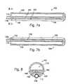
- FIG. 7 ais a section view taken along line 7 a — 7 a in FIG. 4 .
- FIG. 7 bis a section view taken along line 7 b — 7 b in FIG. 4 .
- FIG. 8is a section view taken along line 8 — 8 in FIG. 7 a.
- FIG. 9 ais a section view of an energy transmission assembly in accordance with a preferred embodiment of a present invention.
- FIG. 9 bis a section view of an energy transmission assembly in accordance with a preferred embodiment of a present invention.
- FIG. 10is a plan view of an energy transmission assembly in accordance with a preferred embodiment of a present invention.
- FIG. 11is a section view taken along line 11 — 11 in FIG. 10 .
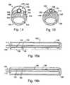
- FIG. 12is a section view of an energy transmission assembly in accordance with a preferred embodiment of a present invention.
- FIG. 13is a section view of an energy transmission assembly in accordance with a preferred embodiment of a present invention.
- FIG. 14is a section view taken along line 14 — 14 in FIG. 13 .
- FIG. 15is a section view of an energy transmission assembly in accordance with a preferred embodiment of a present invention.
- FIG. 16 ais a section view of an energy transmission assembly in accordance with a preferred embodiment of a present invention.
- FIG. 16 bis a section view of an energy transmission assembly in accordance with a preferred embodiment of a present invention.
- FIG. 17is a section view of a probe support device in accordance with a preferred embodiment of a present invention.
- FIG. 18is a section view taken along line 18 — 18 in FIG. 17 .
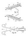
- FIG. 19is a partial plan view showing a pair of the probe support devices illustrated in FIG. 17 supporting a pair of probes on a clamp.
- FIG. 20is a plan view showing a pair of the probe support devices illustrated in FIG. 17 supporting a pair of probes on a clamp.
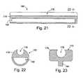
- FIG. 21is a section view of a probe support device in accordance with a preferred embodiment of a present invention.
- FIG. 22is a section view taken along line 21 — 21 in FIG. 20 .
- FIG. 23is a section view of a probe support device in accordance with a preferred embodiment of a present invention.
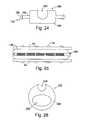
- FIG. 24is an end view of a probe support device in accordance with a preferred embodiment of a present invention.
- FIG. 25is a plan view of a probe support device illustrated in FIG. 24 .
- FIG. 26is an end view of a probe support device in accordance with a preferred embodiment of a present invention.
- FIG. 27is a plan view of a clamp in accordance with a preferred embodiment of a present invention.
- FIG. 28is a plan view of a mandrel in accordance with a preferred embodiment of a present invention.
- FIG. 29is a side view of the mandrel illustrated in FIG. 28 .
- FIGS. 30 and 31are plan views of the clamp illustrated in FIG. 27 being bent with the mandrel illustrated in FIG. 28 .
- FIG. 32is a plan view showing one example of how the clamp illustrated in FIG. 27 may be bent.
- FIG. 33is a plan view showing another example of how the clamp illustrated in FIG. 27 may be bent.
- FIG. 34is a plan view of a clamp in accordance with a preferred embodiment of a present invention.
- This specificationdiscloses a number of structures, mainly in the context of cardiac ablation, because the structures are well suited for use with myocardial tissue. Nevertheless, it should be appreciated that the structures are applicable for use in therapies involving other types of soft tissue. For example, various aspects of the present inventions have applications in procedures concerning other regions of the body such as the prostate, liver, brain, gall bladder, uterus and other solid organs.
- Energy transmission assemblies in accordance with a present inventionmay be used to covert a conventional clamp into a tissue coagulation device.
- the energy transmission assembliesmay also be used to covert a clamp in accordance with the inventions described in Section V below into a tissue coagulation device.
- FIGS. 1-3One example of a conventional clamp that may be used in conjunction with the present inventions is generally represented by reference numeral 10 in FIGS. 1-3 .
- the clamp 10includes a pair of rigid arms 12 and 14 that are pivotably connected to one another by a pin 16 .
- the proximal ends of the arms 12 and 14are respectively connected to a pair handle members 18 and 20 , while the distal ends are respectively connected to a pair of rigid clamp members 22 and 24 .
- a locking device 26locks the clamp in the closed orientation, and prevents the clamp members 22 and 24 from coming any closer to one another than is illustrated in FIG. 1 , thereby defining a predetermined spacing between the clamp members.
- the clamp 10also includes a pair of soft, deformable inserts 28 and 30 that are removably carried by the clamp members 22 and 24 .
- the inserts 28 and 30allow clamp 10 to firmly grip a bodily structure 32 without damaging the bodily structure.
- the inserts 28 and 30include mating structures 34 that extend through corresponding apertures 36 in the clamp members 22 and 24 to hold the inserts in place.
- an apparatus 100 for converting the clamp 10 (which has had the inserts 28 and 30 removed) into a bi-polar tissue coagulation deviceincludes a pair of energy transmission assemblies 102 and 104 .
- Each of the energy transmission assembliesincludes a base member 106 that may be removably secured to one of the clamp members 22 and 24 and an energy transmission device 108 .
- the energy transmission devices 108are discussed in greater detail in Section II below.
- the configuration of the energy transmission assemblies 102 and 104may vary from application to application to suit particular situations, the energy transmission assemblies in the exemplary embodiment are configured such that they will abut one another in the same manner as the inserts 28 and 30 ( FIGS. 1-3 ) when the clamp 10 is in the closed orientation illustrated in FIG. 5 . Such an arrangement will allow the energy transmission assemblies 102 and 104 to grip a bodily structure in the same manner as the inserts 28 and 30 .
- the exemplary base members 106are preferably formed from a soft, resilient, low durometer material that is electrically insulating. Suitable materials include polyurethane, silicone and polyurethane/silicone blends having a hardness of between about 20 Shore D and about 72 Shore D. Referring to FIGS. 7 a , 7 b and 8 , each of the exemplary base members 106 includes a longitudinally extending aperture 110 into which one of the clamp members 22 and 24 may be inserted. The apertures 110 should be sized and shaped such that the base members 106 will be forced to stretch when the clamp members 22 and 24 are inserted. If, for example, the apertures 110 have the same cross-sectional shape as the clamp members 22 and 24 (e.g.
- the apertures 110should be slightly smaller in their cross-sectional dimensions than the corresponding clamp members.
- the stretching of the apertures 110creates a tight interference fit between the base members 106 and clamp members 22 and 24 .
- the apertures 110may have a semi-circular cross-section in the exemplary embodiment, the apertures may have a round, rectangular, square or elliptical cross-section, or define any other cross-sectional shape, depending on the particular application.
- the exemplary base members 106also include slots 112 ( FIG. 8 ) that secure the energy transmission devices 108 in place.
- the configuration of a slot 112will, of course, depend on the configuration of the energy transmission device 108 that it is holding.
- the illustrated energy transmission device 108is generally cylindrical in shape and the slot 112 has a corresponding arcuate cross-sectional shape.
- the arcis preferably greater than 180 degrees so that the base member 106 will deflect when the energy transmission device 108 is inserted into the slot 112 and then snap back to hold the energy transmission device in place.
- Adhesivemay also be used to secure the energy transmission devices 108 , especially in those instances where the arc is less than 180 degrees.
- FIGS. 9 a and 9 bAnother exemplary apparatus for converting the clamp 10 (which has had the inserts 28 and 30 removed) into a bi-polar tissue coagulation device is illustrated in FIGS. 9 a and 9 b .
- the apparatusincludes a pair of energy transmission assemblies 114 and 116 which are substantially similar to the energy transmission assemblies 102 and 104 and similar elements are represented by similar reference numerals.
- Each of the energy transmission assemblies 114 and 116includes a base member 106 ′ that may be removably secured to one of the clamp members 22 and 24 and an energy transmission device 108 .
- the base members 106 ′are secured to the clamp members 22 and 24 with mating structures 118 that mechanically engage the clamp members.
- the exemplary mating structures 118which are preferably integral with the base members 106 ′ and formed from the same resilient material, include a relatively narrow portion 120 and a relatively wide portion 122 .
- the relatively narrow portionsare approximately the same size as the clamp member apertures 36 and the relatively wide portions 122 are slightly larger than the clamp member apertures.
- a removable connectionis made by urging the mating structures 118 into one end of the apertures 36 , thereby deforming the relatively wide portions 122 , and then urging the base members 106 ′ against the clamp members 22 and 24 until the relatively wide portions exit through the other end of the apertures and reassume their original shape.
- the exemplary mating structures 118may also be reconfigured by eliminating the relatively wide portions 122 and enlarging the relatively narrow portions 120 such that the relatively narrow portions will create an interference fit within the clamp member apertures 36 .
- longitudinally extending mating structureswhich also create an interference fit, may be employed when longitudinally extending slots are formed in the clamp members.
- Another alternativeis to provide the clamp members with one or more small mating structures that extend outwardly therefrom. The clamp member mating structures will be received within apertures or slots formed in the base member.
- an energy transmission assembly 124may be used to convert the clamp 10 (which has had the inserts 28 and 30 removed) into a uni-polar tissue coagulation device.
- the energy transmission assembly 124includes a base member 126 , which may be removably secured to both of the clamp members 22 and 24 , and a plurality of spaced energy transmission devices 108 .
- the configuration of the energy transmission assembly 124may vary from application to application to suit particular situations, the energy transmission assembly in the exemplary embodiment is configured such that it will abut each of the clamp members when the clamp 10 is in the closed orientation illustrated in FIG. 10 .
- the exemplary base member 126is preferably formed from a soft, resilient, low durometer material that is electrically insulating. Suitable materials include polyurethane, silicone and polyurethane/silicone blends having a hardness of between about 20 Shore D and about 72 Shore D.
- a slot 128secures the energy transmission devices 108 in place. Although the configuration of the slot 128 will depend on the configuration of the energy transmission devices 108 , the exemplary slot has an arcuate cross-sectional shape that conforms to the shape of the exemplary cylindrical energy transmission devices. The arc is preferably greater than 180 degrees so that the base member 126 will deflect when the energy transmission devices 108 are inserted into the slot 128 and then snap back to hold the energy transmission devices in place. Adhesive may also be used to secure the energy transmission devices 108 in place, especially in those instances where the arc is less than 180 degrees.
- the base member 126is removably secured to the clamp members 22 and 24 with two sets of the mating structures 118 that are described above with reference to FIGS. 9 a and 9 b (with or without the relatively wide portions 122 ).
- the energy transmission assembly 124may be provided with longitudinally extending mating structures 130 that extend outwardly from the base member 126 ′.
- the longitudinally extending mating structures 130which are preferably integral with the base member 126 ′ and formed from the same resilient material, are sized and shaped to create an interference fit with the slots 38 .
- Still another alternativeis to provide the clamp members with one or more small mating structures that are received within apertures or slots formed in the base member.
- the energy transmission assembly 132includes a base member 134 that is preferably formed from a soft, resilient, low durometer material and a plurality of energy transmission devices 108 .
- the material which forms the base member 134should also be electrically insulating. Suitable materials include polyurethane, silicone and polyurethane/silicone blends having a hardness of between about 20 Shore D and about 72 Shore D.
- a slot 128which secures the energy transmission devices 108 in place in the manner described above with reference to FIGS. 10 and 11 , is also provided.
- the exemplary base member 134includes a longitudinally extending aperture 136 into which both of the clamp members 22 and 24 may be inserted.
- the aperture 136should be sized and shaped such that the base member 134 will be forced to stretch when the clamp members 22 and 24 are inserted with the clamp 10 in a closed orientation. The stretching creates a tight interference fit between the base member 134 and the clamp members 22 and 24 .
- the apertures 110have an elliptical cross-section in the exemplary embodiment, the apertures may have a round, rectangular, square or semi-circular cross-section, or define any other cross-sectional shape, depending on the particular application.
- the length of the base members in the exemplary energy transmission assemblieswill vary according to the intended application. In the area of cardiovascular treatments, it is anticipated that suitable lengths will range from, but are not limited to, about 2 cm to about 10 cm.
- the exemplary energy transmission assemblies described abovemay also be modified in a variety of ways.
- the energy transmission assembly illustrated in FIGS. 10 and 11may be converted into a bi-polar device by simply adding a second slot 128 that is preferably spaced apart from and parallel to the existing slot.
- the second slot 128could, for example, include a single return energy transmission device 108 or a plurality of spaced return energy transmission devices.
- the base members and energy transmission devices in the illustrated embodimentsare configured such that the energy transmission devices are generally linear and parallel to the longitudinal axis of the base members (when the assemblies are in a relaxed state and not being urged against a body structure).
- the base members and/or energy transmission devicesmay be reconfigured such that the energy transmission devices, or a portion thereof, are curved and/or non-parallel to the longitudinal axis of the base members when in the relaxed state.
- the energy transmission devicesare electrodes. More specifically, the energy transmission devices are preferably in the form of wound, spiral coil electrodes that are relatively flexible.
- the coilsare made of electrically conducting material, like copper alloy, platinum, or stainless steel, or compositions such as drawn-filled tubing (e.g. a copper core with a platinum jacket).
- the electrically conducting material of the coilscan be further coated with platinum-iridium or gold to improve its conduction properties and biocompatibility.
- a preferred coil electrode configurationis disclosed in U.S. Pat. No. 5,797,905. Although the diameter of the electrodes will very from application to application, the diameter preferably ranges from about 1 mm to about 3 mm for cardiovascular applications.
- the electrodesmay be in the form of solid rings of conductive material, like platinum, or can comprise a conductive material, like platinum-iridium or gold, coated upon the base member using conventional coating techniques or an ion beam assisted deposition (IBAD) process. For better adherence, an undercoating of nickel or titanium can be applied.
- the electrodescan also be in the form of helical ribbons.
- the electrodescan also be formed with a conductive ink compound that is pad printed onto a non-conductive tubular body.
- a preferred conductive ink compoundis a silver-based flexible adhesive conductive ink (polyurethane binder), however other metal-based adhesive conductive inks such as platinum-based, gold-based, copper-based, etc., may also be used to form electrodes. Such inks are more flexible than epoxy-based inks.
- the length of the base memberwill depend on the length of the base member and the intended application.
- the electrodeswill preferably be about 10 mm to about 40 mm in length.
- the electrodeswill be 25 mm in length with 1 mm to 2 mm spacing, which will result in the creation of continuous lesion patterns in tissue when coagulation energy is applied simultaneously to adjacent electrodes.
- the length of the each electrodecan vary from about 3 mm to about 10 mm. Using multiple rigid electrodes longer than about 10 mm each adversely effects the overall flexibility of the device, while electrodes having lengths of less than about 2 mm do not consistently form the desired continuous lesion patterns.
- Electrodesmay be substituted for the electrodes.
- Another type of energy transmission device that may be substituted for the electrodesis cryotemperature elements. Here, the energy transmission is the removal of heat from the tissue.
- Still another type of energy transmission device that may be substituted for the electrodesis needle projections for chemical ablation (which are preferably about 1 to 2 mm in length). Here, the energy transmission is the transmission of chemical energy.
- each energy transmission device 108is individually coupled to a wire 137 ( FIG. 8 ) that conducts coagulating energy.
- the wires 137pass in conventional fashion through cables 138 to an associated connector ( 140 or 142 ).
- the connectors 140 and 142are configured to plug into an electrosurgical unit (“ESU”) 144 that supplies and controls power, such RF power.
- ESUelectrosurgical unit
- a suitable ESUis the Model 4810 ESU sold by EP Technologies, Inc. of San Jose, Calif.
- the exemplary ESU 144 illustrated in FIG. 6includes a plurality of displays and buttons that are used to control the level of power supplied to the energy transmission device(s) 108 and the temperature at the energy transmission device(s).
- the ESU 144may also be used to selectively control which of the energy transmission devices receive power.
- the amount of power required to coagulate tissueranges from 5 to 150 w.
- the exemplary ESU 144 illustrated in FIG. 6is operable in a bi-polar mode, where tissue coagulation energy emitted by the energy transmission device(s) 108 on one energy transmission assembly is returned through the energy transmission device(s) on another energy transmission assembly, and a uni-polar mode, where the tissue coagulation energy emitted by the energy transmission device(s) on an energy transmission assembly is returned through one or more indifferent electrodes (not shown) that are externally attached to the skin of the patient with a patch or one or more electrodes (not shown) that are positioned in the blood pool.
- the exemplary ESU 144is provided with a power output connector 141 and a pair of return connectors 143 .
- the ESU output and return connectors 141 and 143have different shapes to avoid confusion and the connectors 140 and 142 have corresponding shapes.
- the connector 140 associated with energy transmission assembly 102has a shape corresponding to the ESU output connector 141 and the connector 142 associated with energy transmission assembly 104 has a shape corresponding to the ESU return connector 143 .
- the connector (not shown) associated with the energy transmission assembly 124 illustrated in FIG. 10which is intended to be operated in the uni-polar mode, would have a shape corresponding to the ESU output connector 141 .
- a second energy transmission assemblymay be provided with a connector having a shape corresponding to the ESU return connector 143 .
- the assemblywould be provided with a pair of connectors. One would have a shape corresponding to the ESU output connector 141 and the other would have a shape corresponding to the ESU return connector 143 .
- one or more temperature sensors 146may be located on, under, abutting the longitudinal end edges of, or in between, the energy transmission devices 108 .
- a reference thermocouple(not shown) may also be provided.
- signals from the temperature sensors 146are transmitted to the ESU 144 by way of wires 148 ( FIG. 8 ) that are connected to the connector 140 and, in some instances, the connector 142 .
- the wires 137 and 148(which are not shown in all of the Figures for clarity purposes) run through wire apertures 150 and small holes 152 , which are formed in the base members 106 , 126 , 126 ′, 134 and 134 ′.
- Suitable temperature sensors and power control schemesthat are based on a sensed temperature are disclosed in U.S. Pat. Nos. 5,456,682, 5,582,609 and 5,755,715.
- both of the energy transmission assemblies 102 and 104include a single energy transmission device 108 and the energy transmission assembly 102 includes a plurality of spaced temperature sensors 146 .
- the level of power supplied to the energy transmission device 108 on the energy transmission assembly 102would be controlled based on the highest temperature measured by the temperature sensors 146 .
- the energy transmission assembly 104(which is being used as the return) may also provided with a plurality of spaced temperature sensors 146 .
- the level of power supplied to the energy transmission device 108 on the energy transmission assembly 102would be controlled based on the highest temperature measured by any of the temperature sensors 146 , whether on the transmitting assembly 102 or the return assembly 104 .
- a temperature sensor 146may be associated with each of the energy transmission devices.
- power to the energy transmission devices 108may be individually controlled based on the temperature measured by the associated temperature sensor 146 .
- FIGS. 16 a and 16 bAnother exemplary bi-polar arrangement, which is illustrated in FIGS. 16 a and 16 b , is substantially similar to the arrangement illustrated in FIGS. 7 a and 7 b and similar reference numerals are used to represent similar elements.
- the energy transmission assembly 102 ′includes a plurality of spaced energy transmission device 108 , each having a temperature sensor 146 associated therewith, and the energy transmission assembly 104 ′ includes a single energy transmission device 108 and a plurality of temperature sensors 146 .
- the temperature sensors 146are preferably positioned such that, when in use, the temperature sensors on the energy transmission assembly 102 ′ will be aligned with the temperature sensors on the energy transmission assembly 104 ′.
- Such an arrangementallows power to the energy transmission devices 108 on the assembly 102 ′ to be individually controlled based on the highest of two temperatures, i.e. the temperature measured by the temperature sensor 146 associated with the particular energy transmission device and the temperature measured by the temperature sensor directly across from the particular energy transmission device.
- Energy transmission devices in accordance with the present inventionsmay also include apparatus that cools the tissue during tissue coagulation procedures.
- suitable cooling apparatusare illustrated in FIGS. 13-15 .
- tissue cooling apparatusmay also be used in conjunction with the exemplary devices illustrated in FIGS. 4 , 5 , 7 a - 12 , 16 a and 16 b .
- the tissue cooling apparatus disclosed hereinemploy conductive fluid to cool tissue during coagulation procedures. More specifically, and as described below and in U.S. application Ser. No. 09/761,981 (which is incorporated herein by reference), heat from the tissue being coagulated is transferred to ionic fluid to cool the tissue while energy is transferred from an electrode or other energy transmission device to the tissue through the fluid by way of ionic transport.
- the conductive fluidmay be pumped through the tissue cooling apparatus ( FIGS. 13 and 14 ) or the tissue cooling apparatus may be saturated with the fluid prior to use (FIG. 15 ). In either case, cooling tissue during a coagulation procedure facilitates the formation of lesions that are wider and deeper than those that could be realized with an otherwise identical device which lacks tissue cooling apparatus.
- an exemplary tissue cooling apparatus 154includes a nanoporous outer casing 156 through which ionic fluid (represented by arrows F) is transferred.
- the ionic fluidpreferably flows from one longitudinal end of the tissue cooling apparatus 154 to the other.
- the outer casing 156is secured to the base member 134 over the energy transmission devices 108 such that a fluid transmission space 158 is defined therebetween. More specifically, the proximal and distal ends of the outer casing 156 are secured to the base member 134 with anchoring devices (not shown) such as lengths of heat shrink tubing, Nitinol tubing or other mechanical devices that form an interference fit between the casing and the base member. Adhesive bonding is another method of securing the outer casing 156 to the base member 134 .
- the fluid transmission spacewill typically be about 0.5 mm to about 2.0 mm high and slightly wider than the associated energy transmission device(s) 108 .
- the ionic fluidis supplied under pressure from a fluid source (not shown) by way of a supply line 160 and is returned to the source by way of a return line 162 .
- the supply line 160is connected to a fluid lumen 164 that runs from the proximal end of the base member 134 to the distal region of the outer casing 156 .
- the fluid lumen 164is connected to the fluid transmission space 158 by an aperture 166 .
- the electrically conductive ionic fluidpreferably possesses a low resistivity to decrease ohmic loses, and thus ohmic heating effects, within the outer casing 156 .
- the composition of the electrically conductive fluidcan vary.
- the fluidis a hypertonic saline solution, having a sodium chloride concentration at or near saturation, which is about 5% to about 25% weight by volume.
- Hypertonic saline solutionhas a relatively low resistivity of only about 5 ohm-cm, as compared to blood resistivity of about 150 ohm-cm and myocardial tissue resistivity of about 500 ohm-cm.
- the ionic fluidcan be a hypertonic potassium chloride solution.
- a suitable inlet temperature for epicardial applications(the temperature will, of course, rise as heat is transferred to the fluid) is about 0 to 25° C. with a constant flow rate of about 2 to 20 ml/min.
- the flow rate required for endocardial applications where blood is presentwould be about three-fold higher (i.e. 6 to 60 ml/min.). Should applications so require, a flow rate of up to 100 ml/min. may be employed.
- a volume of fluid between about 200 and 500 ml within the bagwill remain at room temperature (about 22° C.) when the flow rate is between about 2 ml/min. and 20 ml/min.
- the flexible bagshould include enough fluid to complete the procedure. 160 ml would, for example, be required for a 20 minute procedure where the flow rate was 8 ml/min.
- the fluid pressure within the outer casing 156should be about 30 mm Hg in order to provide a structure that will resiliently conform to the tissue surface in response to a relatively small force normal to the tissue. Pressures above about 100 mm Hg will cause the outer casing 156 to become too stiff to properly conform to the tissue surface. For that reason, the flow resistance to and from the outer casing 156 should be relatively low.
- the pores in the nanoporous outer casing 156allow the transport of ions contained in the fluid through the casing and into contact with tissue.
- an energy transmission device 108transmit RF energy into the ionic fluid
- the ionic fluidestablishes an electrically conductive path through the outer casing 156 to the tissue being coagulated.
- Regenerated cellulose membrane materialstypically used for blood oxygenation, dialysis or ultrafiltration, are a suitable nanoporous material for the outer casing 156 .
- the thickness of the materialshould be about 0.002 to 0.005 inch.
- regenerated celluloseis electrically non-conductive, the relatively small pores of this material allow effective ionic transport in response to the applied RF field. At the same time, the relatively small pores prevent transfer of macromolecules through the material, so that pressure driven liquid perfusion is less likely to accompany the ionic transport, unless relatively high pressure conditions develop within the outer casing 156 .
- Hydro-FluoroTM materialwhich is disclosed in U.S. application Ser. No. 09/573,071, filed May 16, 2000, is another material that may be used.
- Materialssuch as nylons (with a softening temperature above 100° C.), PTFE, PEI and PEEK that have nanopores created through the use of lasers, electrostatic discharge, ion beam bombardment or other processes may also be used. Such materials would preferably include a hydrophilic coating.
- Nanoporous materialsmay also be fabricated by weaving a material (such as nylon, polyester, polyethylene, polypropylene, fluorocarbon, fine diameter stainless steel, or other fiber) into a mesh having the desired pore size and porosity. These materials permit effective passage of ions in response to the applied RF field. However, as many of these materials possess larger pore diameters, pressure driven liquid perfusion, and the attendant transport of macromolecules through the pores, are also more likely to occur.
- the electrical resistivity of the outer casing 156will have a significant influence on lesion geometry and controllability.
- Low-resistivity(below about 500 ohm-cm) requires more RF power and results in deeper lesions, while high-resistivity (at or above about 500 ohm-cm) generates more uniform heating and improves controllability. Because of the additional heat generated by the increased body resistivity, less RF power is required to reach similar tissue temperatures after the same interval of time. Consequently, lesions generated with high-resistivity structures usually have smaller depth.
- the electrical resistivity of the outer casingcan be controlled by specifying the pore size of the material, the porosity of the material, and the water adsorption characteristics (hydrophilic versus hydrophobic) of the material. A detailed discussion of these characteristics is found in U.S. Pat. No. 5,961,513.
- a suitable electrical resistivity for epicardial and endocardial lesion formationis about 1 to 3000 ohm-cm measured wet.
- liquid perfusion through the nanoporous outer casing 156is preferred.
- ionic transportcreates a continuous virtual electrode at the tissue interface.
- the virtual electrodeefficiently transfers RF energy without need for an electrically conductive metal surface.
- Pore diameters smaller than about 0.1 ⁇ mretain macromolecules, but allow ionic transfer through the pores in response to the applied RF field. With smaller pore diameters, pressure driven liquid perfusion through the pores is less likely to accompany the ionic transport, unless relatively high pressure conditions develop within the outer casing 156 . Larger pore diameters (up to 8 ⁇ m) can also be used to permit ionic current flow across the membrane in response to the applied RF field. With larger pore diameters, pressure driven fluid transport across the membrane is much higher and macromolecules (such as protein) and even small blood cells (such as platelets) could cross the membrane and contaminate the inside of the probe. Red blood cells would normally not cross the membrane barrier, even if fluid perfusion across the membrane stops.
- macromoleculessuch as protein
- small blood cellssuch as platelets
- a pore diameter of 1 to 5 ⁇ mis suitable for epicardial and endocardial lesion formation. Where a larger pore diameter is employed, thereby resulting in significant fluid transfer through the porous region, a saline solution having a sodium chloride concentration of about 0.9% weight by volume would be preferred.
- porositywhich represents the volumetric percentage of the outer casing 156 that is composed of pores and not occupied by the casing material
- the magnitude of the porosityaffects electrical resistance.
- Low-porosity materialshave high electrical resistivity, whereas high-porosity materials have low electrical resistivity.
- the porosity of the outer casing 156should be at least 1% for epicardial and endocardial applications employing a 1 to 5 ⁇ m pore diameter.
- hydrophilic materialsare generally preferable because they possess a greater capacity to provide ionic transfer of RF energy without significant liquid flow through the material.
- the exemplary tissue cooling apparatus 168 illustrated in FIG. 15consists of a wettable fluid retention element 170 that is simply saturated with ionic fluid (such as saline) prior to use, as opposed to having the fluid pumped through the apparatus in the manner described above with reference to FIGS. 13 and 14 .
- the energy transmission device(s) 108are carried within the fluid retention element 170 .
- Suitable materials for the fluid retention element 170include biocompatible fabrics commonly used for vascular patches (such as woven Dacron®), open cell foam materials, hydrogels, nanoporous balloon materials (with very slow fluid delivery to the surface), and hydrophilic nanoporous materials.
- the effective electrical resistivity of the fluid retention element 170 when wefted with 0.9% saline (normal saline)should range from about 1 ⁇ -cm to about 2000 ⁇ -cm.
- a preferred resistivity for epicardial and endocardial proceduresis about 1000 ⁇ -cm.
- Probe support devices in accordance with a present inventionmay be used to covert a conventional clamp, or a clamp in accordance with the inventions described in Section V below, into a tissue coagulation device by securing one or more conventional catheters, surgical probes, or other apparatus that support energy transmission devices, to the clamp.
- the configuration of the probe support devicesmay vary from application to application to suit particular situations, the exemplary probe support devices are configured such that the probes being supported will abut one another in the same manner as the inserts 28 and 30 ( FIGS. 1-3 ) when the associated clamp is in the closed orientation. Such an arrangement will allow the energy transmission devices on the probes to face one another in the manner similar to that described in Section I above.
- a probe support device 172in accordance with one embodiment of a present invention includes a base member 174 , a slot 176 configured to receive an electrode supporting device such as a catheter or surgical probe, and a plurality of mating structures 178 that mechanically engage a clamp member.
- the exemplary base member 174is preferably formed from a soft, resilient, low durometer material that is electrically insulating. Suitable materials include polyurethane, silicone and polyurethane/silicone blends having a hardness of between about 20 Shore D and about 72 Shore D.
- the size and shape of the slot 176will, of course, depend on the size and shape of the probe that it is holding. Many probes are generally cylindrical in shape and, according, the exemplary slot 176 has a corresponding arcuate cross-sectional shape. The arc is preferably greater than 180 degrees so that the base member 174 will deflect when a probe is inserted into the slot 176 and then snap back to hold the probe in place.
- the exemplary mating structures 178which are preferably integral with the base member 174 and formed from the same resilient material, include a relatively narrow portion 180 and a relatively wide portion 182 .
- the relatively narrow portions 180are approximately the same size as the clamp member apertures 36 ( FIG. 3 ) and the relatively wide portions 182 are slightly larger than the clamp member apertures.
- a removable connectionis made by urging the mating structures 178 into one end of the apertures 36 , thereby deforming the relatively wide portions 182 , and then urging the base members 174 against the clamp member until the relatively wide portions exit through the other end of the apertures and reassume their original shape.
- each probe 184 in the exemplary implementationincludes a shaft 186 , a plurality of spaced electrodes 188 , and a plurality of temperature sensors (not shown) respectively associated with the electrodes.
- FIGS. 21 and 22Another exemplary probe support device 190 is illustrated in FIGS. 21 and 22 .
- the probe support device 190is similar to the probe support device 172 illustrated in FIGS. 17 and 18 and similar structural element are represented by similar reference numerals.
- the exemplary probe support device 190may also be used in the manner described above with reference to FIGS. 19 and 20 .
- the mating structures 178have been eliminated and the base member 172 is provided with a longitudinally extending aperture 192 into which one of the clamp members 22 and 24 may be inserted.
- the aperture 192should be sized and shaped such that the base member 174 ′ will be forced to stretch when one of the clamp members 22 and 24 is inserted. If, for example, the apertures 192 have the same cross-sectional shape as the clamp members 22 and 24 (e.g. both are elliptical), then the apertures should be slightly smaller in their cross-sectional dimensions than the corresponding clamp members. The stretching of base member 174 ′ creates a tight interference fit between the base member and the clamp member. Additionally, although the aperture 192 has a semi-circular cross-section in the exemplary embodiment, the apertures may have a round, rectangular, square or elliptical cross-section, or define any other cross-sectional shape, depending on the particular application.
- the probe support device 172may be provided with a longitudinally extending mating structure 194 that extends outwardly from the base member 174 .
- the longitudinally extending mating structure 194which is preferably integral with the base member 174 and formed from the same resilient material, is sized to create an interference fit with a slot.
- Still another alternativeis to provide the clamp members with one or more small mating structures that are received within apertures or slots formed in the base member 174 .
- FIGS. 24 and 25An exemplary probe support device 196 that may be used in conjunction with a probe 184 to convert the clamp 10 (which has had the inserts 28 and 30 removed) into a uni-polar tissue coagulation device is illustrated in FIGS. 24 and 25 .
- the configuration of the probe support device 196may vary from application to application to suit particular situations, the probe support device in the exemplary embodiment is configured such that it will abut each of the clamp members 22 and 24 when the clamp is in the closed orientation illustrated in FIG. 25 .
- the exemplary probe support device 196includes a base member 198 , a slot 200 configured to receive a probe 184 or other electrode supporting device, and a plurality of mating structures 178 that mechanically engage a clamp members 22 and 24 in the manner described above.
- the exemplary base member 198is preferably formed from a soft, resilient, low durometer material that is electrically insulating. Suitable materials include polyurethane, silicone and polyurethane/silicone blends having a hardness of between about 20 Shore D and about 72 Shore D.
- the size and shape of the slot 200will depend on the size and shape of the probe that it is intended to hold.
- the exemplary probe 184is generally cylindrical in shape and, according, the exemplary slot 200 has a corresponding arcuate cross-sectional shape. The arc is preferably greater than 180 degrees so that the base member 198 will deflect when the probe 184 is inserted into the slot 200 and then snap back to hold the probe in place.
- the probe support device 202includes a base member 204 , a slot 206 configured to receive a probe 184 or other electrode supporting device, and a longitudinally extending aperture 208 into which both of the clamp members 22 and 24 may be inserted.
- the exemplary base member 204is preferably formed from a soft, resilient, low durometer material that is electrically insulating. Suitable materials include polyurethane, silicone and polyurethane/silicone blends having a hardness of between about 20 Shore D and about 72 Shore D.
- the size and shape of the slot 206will depend on the size and shape of the probe that it is intended to hold, as is described above with reference to slot 200 .
- the aperture 208should be sized and shaped such that the base member 204 will be forced to stretch when the clamp members 22 and 24 are inserted with the clamp 10 in a closed orientation. The stretching creates a tight interference fit between the base member 204 and the clamp members 22 and 24 .
- the aperture 208has an elliptical cross-section in the exemplary embodiment, the aperture may have a round, rectangular, square or semi-circular cross-section, or define any other cross-sectional shape, depending on the particular application.
- the length of the base members in the exemplary probe support deviceswill vary according to the intended application. In the area of cardiovascular treatments, it is anticipated that suitable lengths will range from, but are not limited to, about 3 cm to about 10 cm.
- a rigid structureis a structure than cannot be readily bent by a physician.
- a malleable structurecan be readily bent by the physician to a desired shape, without springing back when released, so that it will remain in that shape during the surgical procedure.
- the stiffness of a malleable structuremust be low enough to allow the structure to be bent, but high enough to resist bending when the forces associated with a surgical procedure are applied to the structure.
- Rigid structuresare preferably formed from stainless steel, while malleable structure are preferably formed from annealed stainless steel or titanium. Additional information concerning malleable structures may be found in U.S. Pat. No. 6,142,994, which is incorporated herein by reference.
- a clamp 210 in accordance with a preferred embodiment of a present inventionincludes a pair of malleable clamp members 212 and 214 .
- the malleable clamp members 212 and 214are carried at the distal ends of a pair of arms 216 and 218 .
- the arms 216 and 218are pivotably secured to one another by a pin 220 to allow the clamp members 212 and 214 to be moved towards and away from one another between opened and closed positions.
- the arms 216 and 218are preferably formed from rigid material, but may also be malleable if desired. When rigid, the arms 216 and 218 may be linear or have a preformed curvature.
- a pair of handles 222 and 224are mounted on the proximal ends of the arms 216 and 218 .
- a locking device 226locks the clamp 210 in the closed orientation illustrated in FIG. 27 .
- the locking device 226also prevents the clamp members 212 and 214 from coming any closer to one another than is illustrated in FIG. 27 , thereby defining a predetermined spacing between the clamp members.
- the malleability of the clamp members 212 and 214allows them to be re-shaped by the physician as needed for particular procedures and body structures. As such, a single clamp 210 is capable of taking the place of a number of conventional clamps with rigid clamp members. In some implementations, the clamp members 212 and 214 will be more malleable (i.e. easier to bend) at their distal end than at their proximal end. This may be accomplished by gradually decreasing the cross-sectional area of each clamp member 212 and 214 from the proximal end to the distal end.
- the clamp members 212 and 214may also be provided with holes 228 ( FIG. 31 ) that allow soft deformable inserts, such as the conventional inserts 28 and 30 described above with reference to FIGS. 1-3 .
- the exemplary clamp 210may also be used in conjunction with the energy transmission assemblies, probe support devices, and probes described in Sections I-IV above.
- the exemplary clamp 210is provided with a malleable insert 230 that is sized and shaped (rectangular in the exemplary implementation) to be held between the malleable clamp members 212 and 214 when the clamp is closed and locked.
- the friction between the clamp members 212 and 214 and insert 230will hold the insert in place during bending.
- the insert 230may be provided with small protrusions that will be received by the holes 228 .
- the malleable insert 230which is preferably formed from the same material as the malleable clamp members 212 and 214 , will bend with the clamp members during the bending process, thereby maintaining the predetermined spacing. [Note FIG. 32 .]
- the exemplary mandrel 232 illustrated in FIGS. 28 and 29may be used to bend the malleable clamp members 212 and 214 .
- the exemplary mandrel 232includes a base 234 and a pair of cylindrical posts 236 and 238 . Posts of other shapes, such as elliptical posts, may also be employed to achieve particular bends.
- the mandrel 232should also be formed from material that is harder than the malleable clamp members 212 and 214 , such as stainless steel or titanium.
- the exemplary mandrel 232may be used to bend the malleable clamp members 212 and 214 in the manners illustrated in FIGS. 30 and 31 .
- the clamp 210may be rotated in the direction of the arrow (or in the opposite direction) until the clamp members 212 and 214 are bent the desired amount.
- the clamp 210may then moved longitudinally and the bending process repeated until the desired bend, such as the exemplary bend illustrated in FIG. 32 , has been achieved.
- the clamp 210can be rotated about its longitudinal axis and bent in other planes, as is illustrated for example in FIGS.
- the malleable clamp members 212 and 214may be bent independently of one another and/or into different shapes.
- the physicianwill simply place the mandrel 232 on a suitable surface and press down the base 234 during a bending procedure.
- structuremay be provided to secure the mandrel 232 to the surface.
- FIG. 34Another example of a clamp in accordance with a preferred embodiment of a present invention is generally represented by reference numeral 240 in FIG. 34 .
- Clamp 240is similar to clamp 210 and similar elements are represented by similar reference numerals.
- the exemplary clamp 240includes malleable clamp members 212 and 214 , pivotable arms 216 and 218 , handles 222 and 224 , and a locking device 226 .
- the arms 216 and 218are pivotably carried by one end of an elongate housing 242 and the malleable clamp members 212 and 214 are carried by a pair of supports 244 and 246 that are pivotably carried the other end of the housing.
- a suitable mechanical linkagelocated within the housing 242 causes the supports 244 and 246 (and clamp members 212 and 214 ) to move relative to one another in response to movement of the arms 216 and 218 .
- the housing 242may be rigid or malleable
- the present clamps with malleable clamp membershave a wide variety of applications.
- One exampleis the formation of transmural epicardial lesions to isolate the sources of focal (or ectopic) atrial fibrillation and, more specifically, the creation of transmural lesions around the pulmonary veins.
- Energy transmission devicesmay be permanently affixed to the malleable clamp members. Energy transmission devices may also be added using the structures described in Sections I-IV above and the clamp may be used as a clamp or as a surgical probe, depending on the structure being used in combination with the clamp. Access to the heart may be obtained via a thoracotomy, thoracostomy or median sternotomy. Ports may also be provided for cameras and other instruments.
- Lesionsmay be created around the pulmonary veins individually or, alternatively, lesions may be created around pairs of pulmonary veins. For example, a first transmural epicardial lesion may be created around the right pulmonary vein pair and a second transmural epicardial lesion may be created around the left pulmonary vein pair. Thereafter, if needed, a linear transmural epicardial lesion may be created between the right and left pulmonary vein pairs. A linear transmural lesion that extends from the lesion between the right and left pulmonary vein pairs to the left atrial appendage may also be formed. Alternatively, a single lesion may be formed around all four of the pulmonary veins.
Landscapes
- Health & Medical Sciences (AREA)
- Surgery (AREA)
- Engineering & Computer Science (AREA)
- Life Sciences & Earth Sciences (AREA)
- Biomedical Technology (AREA)
- Otolaryngology (AREA)
- Nuclear Medicine, Radiotherapy & Molecular Imaging (AREA)
- Plasma & Fusion (AREA)
- Physics & Mathematics (AREA)
- Heart & Thoracic Surgery (AREA)
- Medical Informatics (AREA)
- Molecular Biology (AREA)
- Animal Behavior & Ethology (AREA)
- General Health & Medical Sciences (AREA)
- Public Health (AREA)
- Veterinary Medicine (AREA)
- Surgical Instruments (AREA)
Abstract
Description
This application is a continuation-in-part of U.S. application Ser. No. 09/535,647, filed Mar. 24, 2000, now U.S. Pat. No. 6,692,491, which is incorporated herein by reference.
1. Field of Inventions
The present inventions relate generally to structures for positioning diagnostic and therapeutic elements within the body and, more particularly, to devices which are particularly well suited for the treatment of cardiac conditions.
2. Description of the Related Art
There are many instances where diagnostic and therapeutic elements must be inserted into the body. One instance involves the treatment of cardiac conditions such as atrial fibrillation and atrial flutter which lead to an unpleasant, irregular heart beat, called arrhythmia.
Normal sinus rhythm of the heart begins with the sinoatrial node (or “SA node”) generating an electrical impulse. The impulse usually propagates uniformly across the right and left atria and the atrial septum to the atrioventricular node (or “AV node”). This propagation causes the atria to contract in an organized way to transport blood from the atria to the ventricles, and to provide timed stimulation of the ventricles. The AV node regulates the propagation delay to the atrioventricular bundle (or “HIS” bundle). This coordination of the electrical activity of the heart causes atrial systole during ventricular diastole. This, in turn, improves the mechanical function of the heart. Atrial fibrillation occurs when anatomical obstacles in the heart disrupt the normally uniform propagation of electrical impulses in the atria. These anatomical obstacles (called “conduction blocks”) can cause the electrical impulse to degenerate into several circular wavelets that circulate about the obstacles. These wavelets, called “reentry circuits,” disrupt the normally uniform activation of the left and right atria. Because of a loss of atrioventricular synchrony, the people who suffer from atrial fibrillation and flutter also suffer the consequences of impaired hemodynamics and loss of cardiac efficiency. They are also at greater risk of stroke and other thromboembolic complications because of loss of effective contraction and atrial stasis.
One surgical method of treating atrial fibrillation by interrupting pathways for reentry circuits is the so-called “maze procedure” which relies on a prescribed pattern of incisions to anatomically create a convoluted path, or maze, for electrical propagation within the left and right atria. The incisions direct the electrical impulse from the SA node along a specified route through all regions of both atria, causing uniform contraction required for normal atrial transport function. The incisions finally direct the impulse to the AV node to activate the ventricles, restoring normal atrioventricular synchrony. The incisions are also carefully placed to interrupt the conduction routes of the most common reentry circuits. The maze procedure has been found very effective in curing atrial fibrillation. However, the maze procedure is technically difficult to do. It also requires open heart surgery and is very expensive. Thus, despite its considerable clinical success, only a few maze procedures are done each year.
Maze-like procedures have also been developed utilizing catheters and/or surgical probes (collectively “probes”) that form lesions to create a maze for electrical conduction in a predetermined path. Typically, the lesions are formed by ablating tissue with one or more electrodes. Electromagnetic radio frequency (“RF”) energy applied by the electrode heats, and eventually kills (i.e. “ablates”), the tissue to form a lesion. During the ablation of soft tissue (i.e. tissue other than blood, bone and connective tissue), tissue coagulation occurs and it is the coagulation that kills the tissue. Thus, references to the ablation of soft tissue are necessarily references to soft tissue coagulation. “Tissue coagulation” is the process of cross-linking proteins in tissue to cause the tissue to jell. In soft tissue, it is the fluid within the tissue cell membranes that jells to kill the cells, thereby killing the tissue.
Catheters used to create lesions typically include a relatively long and relatively flexible body that has one or more electrodes on its distal portion. The portion of the catheter body that is inserted into the patient is typically from 23 to 55 inches in length and there may be another 8 to 15 inches, including a handle, outside the patient. The proximal end of the catheter body is connected to the handle which includes steering controls. The length and flexibility of the catheter body allow the catheter to be inserted into a main vein or artery (typically the femoral artery), directed into the interior of the heart, and then manipulated such that the electrode contacts the tissue that is to be ablated. Fluoroscopic imaging is used to provide the physician with a visual indication of the location of the catheter. Exemplary catheters are disclosed in U.S. Pat. No. 5,582,609.
Surgical probes used to create lesions often include a handle, a relatively short shaft that is from 4 inches to 18 inches in length and either rigid or relatively stiff, and a distal section that is from 1 inch to 10 inches in length and either malleable or somewhat flexible. One or more electrodes are carried by the distal section. Surgical probes are used in epicardial and endocardial procedures, including open heart procedures and minimally invasive procedures where access to the heart is obtained via a thoracotomy, thoracostomy or median sternotomy. Exemplary surgical probes are disclosed in U.S. Pat. No. 6,142,994.
Clamps, which have a pair of opposable rigid clamp members that may be used to hold a bodily structure or a portion thereof, are used in many types surgical procedures. Lesion creating electrodes have also been permanently secured to certain types of clamps. Examples of clamps which carry lesion creating electrodes are disclosed in U.S. Pat. No. 6,142,994. Such clamps are particularly useful when the physician intends to position electrodes on opposite sides of a body structure.
As used herein, the term “clamp” includes, but is not limited to, clamps, clips, forceps, hemostats, and any other surgical device that includes a pair of opposable clamp members that hold tissue, at least one of which is movable relative to the other. In some instances, the rigid clamp members are connected to a scissors-like arrangement including a pair of handle supporting arms that are pivotably connected to one another. The clamp members are secured to one end of the arms and the handles are secured to the other end. The clamp members come together as the handles move toward one another. Certain clamps that are particularly useful in minimally invasive procedures also include a pair of handles and a pair of clamp members. Here, however, the clamp members and handles are not mounted on the opposite ends of the same arm. Instead, the handles are carried by one end of an elongate housing and the clamp members are carried by the other. A suitable mechanical linkage located within the housing causes the clamp members to move relative to one another in response to movement of the handles.
The rigid clamp members in conventional clamps may be linear or have a predefined curvature that is optimized for a particular surgical procedure or portion thereof. It is, therefore, necessary to have a wide variety of clamps on hand. In the field of electrophysiology, a wide variety of clamps that have electrodes permanently secured thereto must be kept on hand.
The inventor herein has determined that it would be advantageous to provide physicians with a wide variety of devices, including clamps (both with and without energy transmission devices) and surgical probes that carry energy transmission devices, in a wide variety of shapes, and to do so in a manner that is more cost effective than conventional apparatus.
An apparatus for use with a clamp in accordance with one embodiment of a present invention includes a base member configured to be secured to the clamp and at least one energy transmission device carried by the base member. Such an apparatus provides a number of advantages. For example, such an apparatus may be used to quickly convert a conventional clamp into an electrophysiology device. In those instances where a procedure requires a number of different clamps, the apparatus can be moved from clamp to clamp, thereby eliminating the costs associated with providing a variety of different clamps with energy transmission devices permanently secured thereto.
An apparatus for use with a clamp and a probe that carries at least one energy transmission device in accordance with one embodiment of a present invention includes a base member configured to be secured to the clamp and an engagement device associated with the base member and configured to engage the probe. Such an apparatus provides a number of advantages. For example, such an apparatus may be used to quickly convert a conventional clamp into an electrophysiology device and to achieve better (or merely different) tissue/energy transmission device contact than could be achieved with the probe itself. Additionally, in those instances where a procedure requires a number of different clamps, the apparatus can be moved from clamp to clamp, thereby eliminating the costs associated with providing a variety of different clamps with energy transmission devices permanently secured thereto.
A clamp in accordance with one embodiment of a present invention includes first and second clamp members, at least one of which is malleable, and a movement apparatus that moves at least one of the first and second clamp members relative to the other. Such a clamp provides a number of advantages. For example, the malleable clamp member allows physicians to readily reconfigure the clamp, thereby reducing the number of clamps that must be provide for a particular surgical procedure.
A surgical system in accordance with one embodiment of a present invention includes a clamp with first and second clamp members and a device that removably mounts at least one electrode on at least one of the first and second clamp members. Such a clamp provides a number of advantages. For example, the system may be used both as a conventional clamp and an electrophysiology device.
The above described and many other features and attendant advantages of the present inventions will become apparent as the inventions become better understood by reference to the following detailed description when considered in conjunction with the accompanying drawings.
Detailed description of preferred embodiments of the inventions will be made with reference to the accompanying drawings.
The following is a detailed description of the best presently known modes of carrying out the inventions. This description is not to be taken in a limiting sense, but is made merely for the purpose of illustrating the general principles of the inventions.
The detailed description of the preferred embodiments is organized as follows:
- I. Energy Transmission Assemblies
- II. Energy Transmission Devices, Temperature Sensing and Power Control
- III. Tissue Cooling Apparatus
- IV. Probe Support Devices
- V. Clamp With Malleable Clamp Members
The section titles and overall organization of the present detailed description are for the purpose of convenience only and are not intended to limit the present inventions.
This specification discloses a number of structures, mainly in the context of cardiac ablation, because the structures are well suited for use with myocardial tissue. Nevertheless, it should be appreciated that the structures are applicable for use in therapies involving other types of soft tissue. For example, various aspects of the present inventions have applications in procedures concerning other regions of the body such as the prostate, liver, brain, gall bladder, uterus and other solid organs.
I. Energy Transmission Assemblies
Energy transmission assemblies in accordance with a present invention may be used to covert a conventional clamp into a tissue coagulation device. The energy transmission assemblies may also be used to covert a clamp in accordance with the inventions described in Section V below into a tissue coagulation device.
One example of a conventional clamp that may be used in conjunction with the present inventions is generally represented byreference numeral 10 inFIGS. 1-3 . Theclamp 10 includes a pair ofrigid arms pin 16. The proximal ends of thearms pair handle members rigid clamp members device 26 locks the clamp in the closed orientation, and prevents theclamp members FIG. 1 , thereby defining a predetermined spacing between the clamp members. Theclamp 10 also includes a pair of soft, deformable inserts28 and30 that are removably carried by theclamp members inserts clamp 10 to firmly grip abodily structure 32 without damaging the bodily structure. Theinserts mating structures 34 that extend throughcorresponding apertures 36 in theclamp members
As illustrated for example inFIGS. 4 and 5 , anapparatus 100 for converting the clamp10 (which has had theinserts energy transmission assemblies base member 106 that may be removably secured to one of theclamp members energy transmission device 108. [Theenergy transmission devices 108 are discussed in greater detail in Section II below.] Although the configuration of theenergy transmission assemblies inserts 28 and30 (FIGS. 1-3 ) when theclamp 10 is in the closed orientation illustrated in FIG.5. Such an arrangement will allow theenergy transmission assemblies inserts
Theexemplary base members 106 are preferably formed from a soft, resilient, low durometer material that is electrically insulating. Suitable materials include polyurethane, silicone and polyurethane/silicone blends having a hardness of between about 20 Shore D and about 72 Shore D. Referring toFIGS. 7 a,7band8, each of theexemplary base members 106 includes alongitudinally extending aperture 110 into which one of theclamp members apertures 110 should be sized and shaped such that thebase members 106 will be forced to stretch when theclamp members apertures 110 have the same cross-sectional shape as theclamp members 22 and24 (e.g. both are elliptical), then the apertures should be slightly smaller in their cross-sectional dimensions than the corresponding clamp members. The stretching of theapertures 110 creates a tight interference fit between thebase members 106 andclamp members apertures 110 have a semi-circular cross-section in the exemplary embodiment, the apertures may have a round, rectangular, square or elliptical cross-section, or define any other cross-sectional shape, depending on the particular application.
Theexemplary base members 106 also include slots112 (FIG. 8 ) that secure theenergy transmission devices 108 in place. The configuration of aslot 112 will, of course, depend on the configuration of theenergy transmission device 108 that it is holding. The illustratedenergy transmission device 108 is generally cylindrical in shape and theslot 112 has a corresponding arcuate cross-sectional shape. The arc is preferably greater than 180 degrees so that thebase member 106 will deflect when theenergy transmission device 108 is inserted into theslot 112 and then snap back to hold the energy transmission device in place. Adhesive may also be used to secure theenergy transmission devices 108, especially in those instances where the arc is less than 180 degrees.
Another exemplary apparatus for converting the clamp10 (which has had theinserts FIGS. 9 aand9b. The apparatus includes a pair ofenergy transmission assemblies 114 and116 which are substantially similar to theenergy transmission assemblies energy transmission assemblies 114 and116 includes abase member 106′ that may be removably secured to one of theclamp members energy transmission device 108. Here, however, thebase members 106′ are secured to theclamp members mating structures 118 that mechanically engage the clamp members.
Theexemplary mating structures 118, which are preferably integral with thebase members 106′ and formed from the same resilient material, include a relativelynarrow portion 120 and a relativelywide portion 122. The relatively narrow portions are approximately the same size as theclamp member apertures 36 and the relativelywide portions 122 are slightly larger than the clamp member apertures. A removable connection is made by urging themating structures 118 into one end of theapertures 36, thereby deforming the relativelywide portions 122, and then urging thebase members 106′ against theclamp members
Theexemplary mating structures 118 may also be reconfigured by eliminating the relativelywide portions 122 and enlarging the relativelynarrow portions 120 such that the relatively narrow portions will create an interference fit within theclamp member apertures 36. Alternatively, as discussed below with reference toFIG. 12 , longitudinally extending mating structures, which also create an interference fit, may be employed when longitudinally extending slots are formed in the clamp members. Another alternative is to provide the clamp members with one or more small mating structures that extend outwardly therefrom. The clamp member mating structures will be received within apertures or slots formed in the base member.
Turning toFIGS. 10 and 11 , anenergy transmission assembly 124 may be used to convert the clamp10 (which has had theinserts energy transmission assembly 124 includes abase member 126, which may be removably secured to both of theclamp members energy transmission devices 108. Although the configuration of theenergy transmission assembly 124 may vary from application to application to suit particular situations, the energy transmission assembly in the exemplary embodiment is configured such that it will abut each of the clamp members when theclamp 10 is in the closed orientation illustrated in FIG.10.
Theexemplary base member 126 is preferably formed from a soft, resilient, low durometer material that is electrically insulating. Suitable materials include polyurethane, silicone and polyurethane/silicone blends having a hardness of between about 20 Shore D and about 72 Shore D. Aslot 128 secures theenergy transmission devices 108 in place. Although the configuration of theslot 128 will depend on the configuration of theenergy transmission devices 108, the exemplary slot has an arcuate cross-sectional shape that conforms to the shape of the exemplary cylindrical energy transmission devices. The arc is preferably greater than 180 degrees so that thebase member 126 will deflect when theenergy transmission devices 108 are inserted into theslot 128 and then snap back to hold the energy transmission devices in place. Adhesive may also be used to secure theenergy transmission devices 108 in place, especially in those instances where the arc is less than 180 degrees.
Thebase member 126 is removably secured to theclamp members mating structures 118 that are described above with reference toFIGS. 9 aand9b(with or without the relatively wide portions122). Alternatively, and as illustrated for example inFIG. 12 , in those instances where theclamp members 22′ and24′ include longitudinally extendingslots 38 instead of theapertures 36, theenergy transmission assembly 124 may be provided with longitudinally extendingmating structures 130 that extend outwardly from thebase member 126′. The longitudinally extendingmating structures 130, which are preferably integral with thebase member 126′ and formed from the same resilient material, are sized and shaped to create an interference fit with theslots 38. Still another alternative is to provide the clamp members with one or more small mating structures that are received within apertures or slots formed in the base member.
Another energy transmission assembly that may be used to convert theclamp 10 into a uni-polar tissue coagulation device is generally represented byreference numeral 132 inFIGS. 13 and 14 . Theenergy transmission assembly 132 includes abase member 134 that is preferably formed from a soft, resilient, low durometer material and a plurality ofenergy transmission devices 108. The material which forms thebase member 134 should also be electrically insulating. Suitable materials include polyurethane, silicone and polyurethane/silicone blends having a hardness of between about 20 Shore D and about 72 Shore D. Aslot 128, which secures theenergy transmission devices 108 in place in the manner described above with reference toFIGS. 10 and 11 , is also provided.
Theexemplary base member 134 includes alongitudinally extending aperture 136 into which both of theclamp members aperture 136 should be sized and shaped such that thebase member 134 will be forced to stretch when theclamp members clamp 10 in a closed orientation. The stretching creates a tight interference fit between thebase member 134 and theclamp members apertures 110 have an elliptical cross-section in the exemplary embodiment, the apertures may have a round, rectangular, square or semi-circular cross-section, or define any other cross-sectional shape, depending on the particular application.
The length of the base members in the exemplary energy transmission assemblies will vary according to the intended application. In the area of cardiovascular treatments, it is anticipated that suitable lengths will range from, but are not limited to, about 2 cm to about 10 cm.
The exemplary energy transmission assemblies described above may also be modified in a variety of ways. For example, the energy transmission assembly illustrated inFIGS. 10 and 11 may be converted into a bi-polar device by simply adding asecond slot 128 that is preferably spaced apart from and parallel to the existing slot. Thesecond slot 128 could, for example, include a single returnenergy transmission device 108 or a plurality of spaced return energy transmission devices. Additionally, as illustrated for example inFIGS. 7 aand13, the base members and energy transmission devices in the illustrated embodiments are configured such that the energy transmission devices are generally linear and parallel to the longitudinal axis of the base members (when the assemblies are in a relaxed state and not being urged against a body structure). The base members and/or energy transmission devices may be reconfigured such that the energy transmission devices, or a portion thereof, are curved and/or non-parallel to the longitudinal axis of the base members when in the relaxed state.
II. Energy Transmission Devices, Temperature Sensing and Power Control
In the exemplary embodiments illustrated inFIGS. 4-16 b, the energy transmission devices are electrodes. More specifically, the energy transmission devices are preferably in the form of wound, spiral coil electrodes that are relatively flexible. The coils are made of electrically conducting material, like copper alloy, platinum, or stainless steel, or compositions such as drawn-filled tubing (e.g. a copper core with a platinum jacket). The electrically conducting material of the coils can be further coated with platinum-iridium or gold to improve its conduction properties and biocompatibility. A preferred coil electrode configuration is disclosed in U.S. Pat. No. 5,797,905. Although the diameter of the electrodes will very from application to application, the diameter preferably ranges from about 1 mm to about 3 mm for cardiovascular applications.
As an alternative, the electrodes may be in the form of solid rings of conductive material, like platinum, or can comprise a conductive material, like platinum-iridium or gold, coated upon the base member using conventional coating techniques or an ion beam assisted deposition (IBAD) process. For better adherence, an undercoating of nickel or titanium can be applied. The electrodes can also be in the form of helical ribbons. The electrodes can also be formed with a conductive ink compound that is pad printed onto a non-conductive tubular body. A preferred conductive ink compound is a silver-based flexible adhesive conductive ink (polyurethane binder), however other metal-based adhesive conductive inks such as platinum-based, gold-based, copper-based, etc., may also be used to form electrodes. Such inks are more flexible than epoxy-based inks.
When a single flexible coil electrode is carried by a base member (see, for example,FIG. 7 a), the length will depend on the length of the base member and the intended application. When a plurality of spaced flexible coil electrodes are carried by a base member (see, for example, FIG.10), the electrodes will preferably be about 10 mm to about 40 mm in length. Preferably, the electrodes will be 25 mm in length with 1 mm to 2 mm spacing, which will result in the creation of continuous lesion patterns in tissue when coagulation energy is applied simultaneously to adjacent electrodes. For rigid electrodes, the length of the each electrode can vary from about 3 mm to about 10 mm. Using multiple rigid electrodes longer than about 10 mm each adversely effects the overall flexibility of the device, while electrodes having lengths of less than about 2 mm do not consistently form the desired continuous lesion patterns.
It should also be noted that other energy transmission devices, such as laser arrays, ultrasonic transducers, microwave electrodes, and ohmically heated hot wires, may be substituted for the electrodes. Another type of energy transmission device that may be substituted for the electrodes is cryotemperature elements. Here, the energy transmission is the removal of heat from the tissue. Still another type of energy transmission device that may be substituted for the electrodes is needle projections for chemical ablation (which are preferably about 1 to 2 mm in length). Here, the energy transmission is the transmission of chemical energy.
Referring for example toFIGS. 5-8 , eachenergy transmission device 108 is individually coupled to a wire137 (FIG. 8 ) that conducts coagulating energy. Thewires 137 pass in conventional fashion throughcables 138 to an associated connector (140 or142). Theconnectors exemplary ESU 144 illustrated inFIG. 6 includes a plurality of displays and buttons that are used to control the level of power supplied to the energy transmission device(s)108 and the temperature at the energy transmission device(s). When a plurality of spacedenergy transmission devices 108 are employed, theESU 144 may also be used to selectively control which of the energy transmission devices receive power. The amount of power required to coagulate tissue ranges from 5 to 150 w.
Theexemplary ESU 144 illustrated inFIG. 6 is operable in a bi-polar mode, where tissue coagulation energy emitted by the energy transmission device(s)108 on one energy transmission assembly is returned through the energy transmission device(s) on another energy transmission assembly, and a uni-polar mode, where the tissue coagulation energy emitted by the energy transmission device(s) on an energy transmission assembly is returned through one or more indifferent electrodes (not shown) that are externally attached to the skin of the patient with a patch or one or more electrodes (not shown) that are positioned in the blood pool. To that end, theexemplary ESU 144 is provided with apower output connector 141 and a pair ofreturn connectors 143. In a preferred implementation, the ESU output and returnconnectors connectors FIG. 5 , theconnector 140 associated withenergy transmission assembly 102 has a shape corresponding to theESU output connector 141 and theconnector 142 associated withenergy transmission assembly 104 has a shape corresponding to theESU return connector 143.
The connector (not shown) associated with theenergy transmission assembly 124 illustrated inFIG. 10 , which is intended to be operated in the uni-polar mode, would have a shape corresponding to theESU output connector 141. In those instances where it is desirable to clamp the indifferent electrode within the patient, as opposed to positioning the indifferent electrode on the patient's skin, a second energy transmission assembly may be provided with a connector having a shape corresponding to theESU return connector 143. Additionally, in those instances where theenergy transmission assembly 124 has been modified to include space electrodes (or spaced groups of longitudinally spaced electrodes) that operated in bi-polar fashion, the assembly would be provided with a pair of connectors. One would have a shape corresponding to theESU output connector 141 and the other would have a shape corresponding to theESU return connector 143.
With respect to power and temperature control, one ormore temperature sensors 146, such as thermocouples or thermistors, may be located on, under, abutting the longitudinal end edges of, or in between, theenergy transmission devices 108. A reference thermocouple (not shown) may also be provided. For temperature control purposes, signals from thetemperature sensors 146 are transmitted to theESU 144 by way of wires148 (FIG. 8 ) that are connected to theconnector 140 and, in some instances, theconnector 142. Thewires 137 and148 (which are not shown in all of the Figures for clarity purposes) run throughwire apertures 150 andsmall holes 152, which are formed in thebase members
The actual number oftemperature sensors 146 may be varied in order to suit particular applications. In the bi-polar arrangement illustrated inFIGS. 7 aand7b, for example, both of theenergy transmission assemblies energy transmission device 108 and theenergy transmission assembly 102 includes a plurality of spacedtemperature sensors 146. Here, the level of power supplied to theenergy transmission device 108 on theenergy transmission assembly 102 would be controlled based on the highest temperature measured by thetemperature sensors 146. Alternatively, the energy transmission assembly104 (which is being used as the return) may also provided with a plurality of spacedtemperature sensors 146. Here, the level of power supplied to theenergy transmission device 108 on theenergy transmission assembly 102 would be controlled based on the highest temperature measured by any of thetemperature sensors 146, whether on the transmittingassembly 102 or thereturn assembly 104.
In those instances where a plurality of spacedenergy transmission devices 108 are provided, such as in the uni-polar arrangement illustrated inFIG. 13 , atemperature sensor 146 may be associated with each of the energy transmission devices. Here, power to theenergy transmission devices 108 may be individually controlled based on the temperature measured by the associatedtemperature sensor 146.
Another exemplary bi-polar arrangement, which is illustrated inFIGS. 16 aand16b, is substantially similar to the arrangement illustrated inFIGS. 7 aand7band similar reference numerals are used to represent similar elements. Here, however, theenergy transmission assembly 102′ includes a plurality of spacedenergy transmission device 108, each having atemperature sensor 146 associated therewith, and theenergy transmission assembly 104′ includes a singleenergy transmission device 108 and a plurality oftemperature sensors 146. Thetemperature sensors 146 are preferably positioned such that, when in use, the temperature sensors on theenergy transmission assembly 102′ will be aligned with the temperature sensors on theenergy transmission assembly 104′. Such an arrangement allows power to theenergy transmission devices 108 on theassembly 102′ to be individually controlled based on the highest of two temperatures, i.e. the temperature measured by thetemperature sensor 146 associated with the particular energy transmission device and the temperature measured by the temperature sensor directly across from the particular energy transmission device.
III. Tissue Cooling Apparatus
Energy transmission devices in accordance with the present inventions may also include apparatus that cools the tissue during tissue coagulation procedures. Examples of suitable cooling apparatus are illustrated inFIGS. 13-15 . Such tissue cooling apparatus may also be used in conjunction with the exemplary devices illustrated inFIGS. 4 ,5,7a-12,16aand16b. The tissue cooling apparatus disclosed herein employ conductive fluid to cool tissue during coagulation procedures. More specifically, and as described below and in U.S. application Ser. No. 09/761,981 (which is incorporated herein by reference), heat from the tissue being coagulated is transferred to ionic fluid to cool the tissue while energy is transferred from an electrode or other energy transmission device to the tissue through the fluid by way of ionic transport. The conductive fluid may be pumped through the tissue cooling apparatus (FIGS. 13 and 14 ) or the tissue cooling apparatus may be saturated with the fluid prior to use (FIG.15). In either case, cooling tissue during a coagulation procedure facilitates the formation of lesions that are wider and deeper than those that could be realized with an otherwise identical device which lacks tissue cooling apparatus.
Referring first toFIGS. 13 and 14 , an exemplarytissue cooling apparatus 154 includes a nanoporousouter casing 156 through which ionic fluid (represented by arrows F) is transferred. The ionic fluid preferably flows from one longitudinal end of thetissue cooling apparatus 154 to the other. Theouter casing 156 is secured to thebase member 134 over theenergy transmission devices 108 such that afluid transmission space 158 is defined therebetween. More specifically, the proximal and distal ends of theouter casing 156 are secured to thebase member 134 with anchoring devices (not shown) such as lengths of heat shrink tubing, Nitinol tubing or other mechanical devices that form an interference fit between the casing and the base member. Adhesive bonding is another method of securing theouter casing 156 to thebase member 134. The fluid transmission space will typically be about 0.5 mm to about 2.0 mm high and slightly wider than the associated energy transmission device(s)108.
The ionic fluid is supplied under pressure from a fluid source (not shown) by way of asupply line 160 and is returned to the source by way of areturn line 162. Thesupply line 160 is connected to afluid lumen 164 that runs from the proximal end of thebase member 134 to the distal region of theouter casing 156. Thefluid lumen 164 is connected to thefluid transmission space 158 by anaperture 166.
The electrically conductive ionic fluid preferably possesses a low resistivity to decrease ohmic loses, and thus ohmic heating effects, within theouter casing 156. The composition of the electrically conductive fluid can vary. In the illustrated embodiment, the fluid is a hypertonic saline solution, having a sodium chloride concentration at or near saturation, which is about 5% to about 25% weight by volume. Hypertonic saline solution has a relatively low resistivity of only about 5 ohm-cm, as compared to blood resistivity of about 150 ohm-cm and myocardial tissue resistivity of about 500 ohm-cm. Alternatively, the ionic fluid can be a hypertonic potassium chloride solution.
With respect to temperature and flow rate, a suitable inlet temperature for epicardial applications (the temperature will, of course, rise as heat is transferred to the fluid) is about 0 to 25° C. with a constant flow rate of about 2 to 20 ml/min. The flow rate required for endocardial applications where blood is present would be about three-fold higher (i.e. 6 to 60 ml/min.). Should applications so require, a flow rate of up to 100 ml/min. may be employed. In a closed system where the fluid is stored in a flexible bag, such as the Viaflex® bag manufactured by Baxter Corporation, and heated fluid is returned to the bag, it has been found that a volume of fluid between about 200 and 500 ml within the bag will remain at room temperature (about 22° C.) when the flow rate is between about 2 ml/min. and 20 ml/min. Alternatively, in an open system, the flexible bag should include enough fluid to complete the procedure. 160 ml would, for example, be required for a 20 minute procedure where the flow rate was 8 ml/min.
The fluid pressure within theouter casing 156 should be about 30 mm Hg in order to provide a structure that will resiliently conform to the tissue surface in response to a relatively small force normal to the tissue. Pressures above about 100 mm Hg will cause theouter casing 156 to become too stiff to properly conform to the tissue surface. For that reason, the flow resistance to and from theouter casing 156 should be relatively low.
The pores in the nanoporousouter casing 156 allow the transport of ions contained in the fluid through the casing and into contact with tissue. Thus, when anenergy transmission device 108 transmit RF energy into the ionic fluid, the ionic fluid establishes an electrically conductive path through theouter casing 156 to the tissue being coagulated. Regenerated cellulose membrane materials, typically used for blood oxygenation, dialysis or ultrafiltration, are a suitable nanoporous material for theouter casing 156. The thickness of the material should be about 0.002 to 0.005 inch. Although regenerated cellulose is electrically non-conductive, the relatively small pores of this material allow effective ionic transport in response to the applied RF field. At the same time, the relatively small pores prevent transfer of macromolecules through the material, so that pressure driven liquid perfusion is less likely to accompany the ionic transport, unless relatively high pressure conditions develop within theouter casing 156.
Hydro-Fluoro™ material, which is disclosed in U.S. application Ser. No. 09/573,071, filed May 16, 2000, is another material that may be used. Materials such as nylons (with a softening temperature above 100° C.), PTFE, PEI and PEEK that have nanopores created through the use of lasers, electrostatic discharge, ion beam bombardment or other processes may also be used. Such materials would preferably include a hydrophilic coating. Nanoporous materials may also be fabricated by weaving a material (such as nylon, polyester, polyethylene, polypropylene, fluorocarbon, fine diameter stainless steel, or other fiber) into a mesh having the desired pore size and porosity. These materials permit effective passage of ions in response to the applied RF field. However, as many of these materials possess larger pore diameters, pressure driven liquid perfusion, and the attendant transport of macromolecules through the pores, are also more likely to occur.
The electrical resistivity of theouter casing 156 will have a significant influence on lesion geometry and controllability. Low-resistivity (below about 500 ohm-cm) requires more RF power and results in deeper lesions, while high-resistivity (at or above about 500 ohm-cm) generates more uniform heating and improves controllability. Because of the additional heat generated by the increased body resistivity, less RF power is required to reach similar tissue temperatures after the same interval of time. Consequently, lesions generated with high-resistivity structures usually have smaller depth. The electrical resistivity of the outer casing can be controlled by specifying the pore size of the material, the porosity of the material, and the water adsorption characteristics (hydrophilic versus hydrophobic) of the material. A detailed discussion of these characteristics is found in U.S. Pat. No. 5,961,513. A suitable electrical resistivity for epicardial and endocardial lesion formation is about 1 to 3000 ohm-cm measured wet.
Generally speaking, low or essentially no liquid perfusion through the nanoporousouter casing 156 is preferred. When undisturbed by attendant liquid perfusion, ionic transport creates a continuous virtual electrode at the tissue interface. The virtual electrode efficiently transfers RF energy without need for an electrically conductive metal surface.
Pore diameters smaller than about 0.1 μm retain macromolecules, but allow ionic transfer through the pores in response to the applied RF field. With smaller pore diameters, pressure driven liquid perfusion through the pores is less likely to accompany the ionic transport, unless relatively high pressure conditions develop within theouter casing 156. Larger pore diameters (up to 8 μm) can also be used to permit ionic current flow across the membrane in response to the applied RF field. With larger pore diameters, pressure driven fluid transport across the membrane is much higher and macromolecules (such as protein) and even small blood cells (such as platelets) could cross the membrane and contaminate the inside of the probe. Red blood cells would normally not cross the membrane barrier, even if fluid perfusion across the membrane stops. On balance, a pore diameter of 1 to 5 μm is suitable for epicardial and endocardial lesion formation. Where a larger pore diameter is employed, thereby resulting in significant fluid transfer through the porous region, a saline solution having a sodium chloride concentration of about 0.9% weight by volume would be preferred.
With respect to porosity, which represents the volumetric percentage of theouter casing 156 that is composed of pores and not occupied by the casing material, the magnitude of the porosity affects electrical resistance. Low-porosity materials have high electrical resistivity, whereas high-porosity materials have low electrical resistivity. The porosity of theouter casing 156 should be at least 1% for epicardial and endocardial applications employing a 1 to 5 μm pore diameter.
Turning to water absorption characteristics, hydrophilic materials are generally preferable because they possess a greater capacity to provide ionic transfer of RF energy without significant liquid flow through the material.
The exemplarytissue cooling apparatus 168 illustrated inFIG. 15 consists of a wettablefluid retention element 170 that is simply saturated with ionic fluid (such as saline) prior to use, as opposed to having the fluid pumped through the apparatus in the manner described above with reference toFIGS. 13 and 14 . The energy transmission device(s)108 are carried within thefluid retention element 170. Suitable materials for thefluid retention element 170 include biocompatible fabrics commonly used for vascular patches (such as woven Dacron®), open cell foam materials, hydrogels, nanoporous balloon materials (with very slow fluid delivery to the surface), and hydrophilic nanoporous materials. The effective electrical resistivity of thefluid retention element 170 when wefted with 0.9% saline (normal saline) should range from about 1 Ω-cm to about 2000 Ω-cm. A preferred resistivity for epicardial and endocardial procedures is about 1000 Ω-cm.
IV. Probe Support Devices
Probe support devices in accordance with a present invention may be used to covert a conventional clamp, or a clamp in accordance with the inventions described in Section V below, into a tissue coagulation device by securing one or more conventional catheters, surgical probes, or other apparatus that support energy transmission devices, to the clamp. Although the configuration of the probe support devices may vary from application to application to suit particular situations, the exemplary probe support devices are configured such that the probes being supported will abut one another in the same manner as theinserts 28 and30 (FIGS. 1-3 ) when the associated clamp is in the closed orientation. Such an arrangement will allow the energy transmission devices on the probes to face one another in the manner similar to that described in Section I above.
As illustrated for example inFIGS. 17 and 18 , aprobe support device 172 in accordance with one embodiment of a present invention includes abase member 174, aslot 176 configured to receive an electrode supporting device such as a catheter or surgical probe, and a plurality ofmating structures 178 that mechanically engage a clamp member. Theexemplary base member 174 is preferably formed from a soft, resilient, low durometer material that is electrically insulating. Suitable materials include polyurethane, silicone and polyurethane/silicone blends having a hardness of between about 20 Shore D and about 72 Shore D.
The size and shape of theslot 176 will, of course, depend on the size and shape of the probe that it is holding. Many probes are generally cylindrical in shape and, according, theexemplary slot 176 has a corresponding arcuate cross-sectional shape. The arc is preferably greater than 180 degrees so that thebase member 174 will deflect when a probe is inserted into theslot 176 and then snap back to hold the probe in place.
Theexemplary mating structures 178, which are preferably integral with thebase member 174 and formed from the same resilient material, include a relativelynarrow portion 180 and a relativelywide portion 182. The relativelynarrow portions 180 are approximately the same size as the clamp member apertures36 (FIG. 3 ) and the relativelywide portions 182 are slightly larger than the clamp member apertures. A removable connection is made by urging themating structures 178 into one end of theapertures 36, thereby deforming the relativelywide portions 182, and then urging thebase members 174 against the clamp member until the relatively wide portions exit through the other end of the apertures and reassume their original shape.
Turning toFIGS. 19 and 20 , a pair of the exemplaryprobe support devices 172 may be used in conjunction with a pair ofprobes 184 to convert the clamp10 (which has had theinserts probe 184 in the exemplary implementation includes ashaft 186, a plurality of spacedelectrodes 188, and a plurality of temperature sensors (not shown) respectively associated with the electrodes. Once theprobe support devices 172 have been secured to theclamp members probes 184 may be snapped into theslots 176 by moving the probes from the dash line positions illustrated inFIG. 19 to the solid line positions. One of theprobes 184 may be connected to the output connector of an ESU, while the other probe may be connected to the return connector to complete the bi-polar arrangement.
Another exemplaryprobe support device 190 is illustrated inFIGS. 21 and 22 . Theprobe support device 190 is similar to theprobe support device 172 illustrated inFIGS. 17 and 18 and similar structural element are represented by similar reference numerals. The exemplaryprobe support device 190 may also be used in the manner described above with reference toFIGS. 19 and 20 . Here, however, themating structures 178 have been eliminated and thebase member 172 is provided with alongitudinally extending aperture 192 into which one of theclamp members
Theaperture 192 should be sized and shaped such that thebase member 174′ will be forced to stretch when one of theclamp members apertures 192 have the same cross-sectional shape as theclamp members 22 and24 (e.g. both are elliptical), then the apertures should be slightly smaller in their cross-sectional dimensions than the corresponding clamp members. The stretching ofbase member 174′ creates a tight interference fit between the base member and the clamp member. Additionally, although theaperture 192 has a semi-circular cross-section in the exemplary embodiment, the apertures may have a round, rectangular, square or elliptical cross-section, or define any other cross-sectional shape, depending on the particular application.
Alternatively, and as illustrated for example inFIG. 23 , in those instances where the clamp members include longitudinally extending slots instead of apertures (such as theslots 38 described above with reference to FIG.12), theprobe support device 172 may be provided with a longitudinally extendingmating structure 194 that extends outwardly from thebase member 174. The longitudinally extendingmating structure 194, which is preferably integral with thebase member 174 and formed from the same resilient material, is sized to create an interference fit with a slot. Still another alternative is to provide the clamp members with one or more small mating structures that are received within apertures or slots formed in thebase member 174.
An exemplaryprobe support device 196 that may be used in conjunction with aprobe 184 to convert the clamp10 (which has had theinserts FIGS. 24 and 25 . Although the configuration of theprobe support device 196 may vary from application to application to suit particular situations, the probe support device in the exemplary embodiment is configured such that it will abut each of theclamp members
The exemplaryprobe support device 196 includes abase member 198, aslot 200 configured to receive aprobe 184 or other electrode supporting device, and a plurality ofmating structures 178 that mechanically engage aclamp members exemplary base member 198 is preferably formed from a soft, resilient, low durometer material that is electrically insulating. Suitable materials include polyurethane, silicone and polyurethane/silicone blends having a hardness of between about 20 Shore D and about 72 Shore D. The size and shape of theslot 200 will depend on the size and shape of the probe that it is intended to hold. Theexemplary probe 184 is generally cylindrical in shape and, according, theexemplary slot 200 has a corresponding arcuate cross-sectional shape. The arc is preferably greater than 180 degrees so that thebase member 198 will deflect when theprobe 184 is inserted into theslot 200 and then snap back to hold the probe in place.
Another exemplary probe support device that may be used in conjunction with aprobe 184 to convert theclamp 10 into a uni-polar tissue coagulation device is generally represented byreference numeral 202 in FIG.26. Theprobe support device 202 includes abase member 204, aslot 206 configured to receive aprobe 184 or other electrode supporting device, and alongitudinally extending aperture 208 into which both of theclamp members exemplary base member 204 is preferably formed from a soft, resilient, low durometer material that is electrically insulating. Suitable materials include polyurethane, silicone and polyurethane/silicone blends having a hardness of between about 20 Shore D and about 72 Shore D. The size and shape of theslot 206 will depend on the size and shape of the probe that it is intended to hold, as is described above with reference to slot200. Theaperture 208 should be sized and shaped such that thebase member 204 will be forced to stretch when theclamp members clamp 10 in a closed orientation. The stretching creates a tight interference fit between thebase member 204 and theclamp members aperture 208 has an elliptical cross-section in the exemplary embodiment, the aperture may have a round, rectangular, square or semi-circular cross-section, or define any other cross-sectional shape, depending on the particular application.
The length of the base members in the exemplary probe support devices will vary according to the intended application. In the area of cardiovascular treatments, it is anticipated that suitable lengths will range from, but are not limited to, about 3 cm to about 10 cm.
V. Clamp With Malleable Clamp Members
This portion of the specification refers to rigid and malleable structures. A rigid structure is a structure than cannot be readily bent by a physician. A malleable structure can be readily bent by the physician to a desired shape, without springing back when released, so that it will remain in that shape during the surgical procedure. Thus, the stiffness of a malleable structure must be low enough to allow the structure to be bent, but high enough to resist bending when the forces associated with a surgical procedure are applied to the structure. Rigid structures are preferably formed from stainless steel, while malleable structure are preferably formed from annealed stainless steel or titanium. Additional information concerning malleable structures may be found in U.S. Pat. No. 6,142,994, which is incorporated herein by reference.
As illustrated for example inFIG. 27 , aclamp 210 in accordance with a preferred embodiment of a present invention includes a pair ofmalleable clamp members malleable clamp members arms arms pin 220 to allow theclamp members arms arms
A pair ofhandles arms locking device 226 locks theclamp 210 in the closed orientation illustrated in FIG.27. Thelocking device 226 also prevents theclamp members FIG. 27 , thereby defining a predetermined spacing between the clamp members.
The malleability of theclamp members single clamp 210 is capable of taking the place of a number of conventional clamps with rigid clamp members. In some implementations, theclamp members clamp member
Theclamp members FIG. 31 ) that allow soft deformable inserts, such as theconventional inserts FIGS. 1-3 . Theexemplary clamp 210 may also be used in conjunction with the energy transmission assemblies, probe support devices, and probes described in Sections I-IV above.
There will be many instances where it will be important to maintain the predefined spacing between themalleable clamp members exemplary clamp 210 is provided with amalleable insert 230 that is sized and shaped (rectangular in the exemplary implementation) to be held between themalleable clamp members clamp members insert 230 may be provided with small protrusions that will be received by theholes 228. Themalleable insert 230, which is preferably formed from the same material as themalleable clamp members
Theexemplary mandrel 232 illustrated inFIGS. 28 and 29 may be used to bend themalleable clamp members exemplary mandrel 232 includes abase 234 and a pair ofcylindrical posts mandrel 232 should also be formed from material that is harder than themalleable clamp members
Theexemplary mandrel 232 may be used to bend themalleable clamp members FIGS. 30 and 31 . Referring first toFIG. 30 , once themalleable clamp members malleable insert 230 have been placed between theposts clamp 210 may be rotated in the direction of the arrow (or in the opposite direction) until theclamp members clamp 210 may then moved longitudinally and the bending process repeated until the desired bend, such as the exemplary bend illustrated inFIG. 32 , has been achieved. Alternatively, or in addition, theclamp 210 can be rotated about its longitudinal axis and bent in other planes, as is illustrated for example inFIGS. 31 and 33 . It should also be noted that, if desired, themalleable clamp members mandrel 232 on a suitable surface and press down the base234 during a bending procedure. Alternatively, structure may be provided to secure themandrel 232 to the surface.
Another example of a clamp in accordance with a preferred embodiment of a present invention is generally represented byreference numeral 240 in FIG.34.Clamp 240 is similar to clamp210 and similar elements are represented by similar reference numerals. Theexemplary clamp 240 includesmalleable clamp members pivotable arms locking device 226. Here, however, thearms elongate housing 242 and themalleable clamp members supports housing 242 causes thesupports 244 and246 (and clampmembers 212 and214) to move relative to one another in response to movement of thearms housing 242 may be rigid or malleable
The present clamps with malleable clamp members (such asexemplary clamps 210 and240) have a wide variety of applications. One example is the formation of transmural epicardial lesions to isolate the sources of focal (or ectopic) atrial fibrillation and, more specifically, the creation of transmural lesions around the pulmonary veins. Energy transmission devices may be permanently affixed to the malleable clamp members. Energy transmission devices may also be added using the structures described in Sections I-IV above and the clamp may be used as a clamp or as a surgical probe, depending on the structure being used in combination with the clamp. Access to the heart may be obtained via a thoracotomy, thoracostomy or median sternotomy. Ports may also be provided for cameras and other instruments.
Lesions may be created around the pulmonary veins individually or, alternatively, lesions may be created around pairs of pulmonary veins. For example, a first transmural epicardial lesion may be created around the right pulmonary vein pair and a second transmural epicardial lesion may be created around the left pulmonary vein pair. Thereafter, if needed, a linear transmural epicardial lesion may be created between the right and left pulmonary vein pairs. A linear transmural lesion that extends from the lesion between the right and left pulmonary vein pairs to the left atrial appendage may also be formed. Alternatively, a single lesion may be formed around all four of the pulmonary veins.
Although the present inventions have been described in terms of the preferred embodiments above, numerous modifications and/or additions to the above-described preferred embodiments would be readily apparent to one skilled in the art. It is intended that the scope of the present inventions extend to all such modifications and/or additions and that the scope of the present inventions is limited solely by the claims set forth below.
Claims (19)
1. A surgical apparatus, comprising:
a first malleable clamp member and a second malleable clamp member;
movement apparatus that moves at least one of the first and second clamp members relative to the other of the first and second clamp members such that the surgical apparatus has an open state and a closed state; and
a malleable spacer configured to be held between the first and second clamp members when the surgical apparatus is in the closed state.
2. A surgical apparatus as claimed inclaim 1 , wherein the first and second clamp members defines respective distal and proximal ends, the proximal ends are spaced apart by a predetermined distance when the surgical apparatus is in the closed state and the malleable spacer defines a thickness that is substantially equal to the predetermined distance.
3. A surgical apparatus as claimed inclaim 1 , wherein the malleable spacer is substantially rectangular in cross-section.
4. A surgical apparatus as claimed inclaim 1 , wherein the movement apparatus comprises first and second arms pivotably secured to one another.
5. A surgical apparatus as claimed inclaim 4 , wherein the first and second arms are substantially rigid.
6. A surgical apparatus as claimed inclaim 4 , wherein the first and second arms define respective distal and proximal ends, the first and second clamp members defines respective distal and proximal ends, the proximal end of the first clamp member is associated with the distal end of the first arm, and the proximal end of the second clamp member is associated with the distal end of the second arm.
7. A surgical apparatus as claimed inclaim 6 , wherein the first and second arms are pivotably secured to one another at a point between the respective proximal and distal ends of the first and second arms.
8. A surgical apparatus as claimed inclaim 1 , wherein the movement apparatus comprises an elongate housing defining proximal and distal portions, first and second pivotable arms associated with the proximal portion, and a mechanical linkage operably connecting the first and second pivotable arms to the first and second clamp members.
9. A surgical apparatus as claimed inclaim 1 , further comprising:
a lock that maintains the apparatus in the closed state.
10. A surgical system:
a first clamp member and a second clamp member, at least one of the first and second clamp members being malleable;
movement apparatus that moves at least one of the first and second clamp members relative to the other of the first and second clamp members such that the surgical apparatus has an open and a closed state; and
a mandrel configured to bend the at least one clamp member.
11. A surgical system as claimed inclaim 10 , wherein each of the first and second clamp members are malleable.
12. A surgical system as claimed inclaim 10 , wherein the movement apparatus comprises first and second arms pivotably secured to one another.
13. A surgical system as claimed inclaim 12 , wherein the first and second arms are substantially rigid.
14. A surgical system as claimed inclaim 10 , wherein the movement apparatus comprises an elongate housing defining proximal and distal portions, first and second pivotable arms associated with the proximal portion, and a mechanical linkage operably connecting the first and second pivotable arms to the first and second clamp members.
15. A surgical method, comprising the step of:
providing a clamp including first and second clamp members, at least the first clamp member being malleable;
bending the first clamp member into a desired shape with a mandrel; and
clamping tissue with the clamp.
16. A surgical method as claimed inclaim 15 , wherein the step of providing a clamp comprises providing a clamp including first and second malleable clamp members.
17. A surgical method as claimed inclaim 16 , further comprising the step of:
bending the second clamp member into a desired shape.
18. A surgical method as claimed inclaim 15 , further comprising the steps of:
unclamping the tissue;
bending the first clamp member into another desired shape; and
re-clamping the tissue.
19. A surgical method as claimed inclaim 15 , further comprising the steps of:
removably securing an energy transmission device onto at least one of the clamp members prior to clamping the tissue; and
forming a lesion with the energy transmission device after the tissue has been clamped.
Priority Applications (3)
| Application Number | Priority Date | Filing Date | Title |
|---|---|---|---|
| US10/080,378US6926712B2 (en) | 2000-03-24 | 2002-02-19 | Clamp having at least one malleable clamp member and surgical method employing the same |
| AU2002348257AAU2002348257A1 (en) | 2002-02-19 | 2002-11-25 | Surgical clamp having at least one malleable clamp member |
| PCT/US2002/038105WO2003070114A1 (en) | 2002-02-19 | 2002-11-25 | Surgical clamp having at least one malleable clamp member |
Applications Claiming Priority (2)
| Application Number | Priority Date | Filing Date | Title |
|---|---|---|---|
| US09/535,647US6692491B1 (en) | 2000-03-24 | 2000-03-24 | Surgical methods and apparatus for positioning a diagnostic or therapeutic element around one or more pulmonary veins or other body structures |
| US10/080,378US6926712B2 (en) | 2000-03-24 | 2002-02-19 | Clamp having at least one malleable clamp member and surgical method employing the same |
Related Parent Applications (1)
| Application Number | Title | Priority Date | Filing Date |
|---|---|---|---|
| US09/535,647Continuation-In-PartUS6692491B1 (en) | 2000-03-24 | 2000-03-24 | Surgical methods and apparatus for positioning a diagnostic or therapeutic element around one or more pulmonary veins or other body structures |
Publications (2)
| Publication Number | Publication Date |
|---|---|
| US20020120267A1 US20020120267A1 (en) | 2002-08-29 |
| US6926712B2true US6926712B2 (en) | 2005-08-09 |
Family
ID=27752808
Family Applications (1)
| Application Number | Title | Priority Date | Filing Date |
|---|---|---|---|
| US10/080,378Expired - LifetimeUS6926712B2 (en) | 2000-03-24 | 2002-02-19 | Clamp having at least one malleable clamp member and surgical method employing the same |
Country Status (3)
| Country | Link |
|---|---|
| US (1) | US6926712B2 (en) |
| AU (1) | AU2002348257A1 (en) |
| WO (1) | WO2003070114A1 (en) |
Cited By (188)
| Publication number | Priority date | Publication date | Assignee | Title |
|---|---|---|---|---|
| US20030158549A1 (en)* | 2002-02-19 | 2003-08-21 | Swanson David K. | Apparatus for securing an electrophysiology probe to a clamp |
| US20030158548A1 (en)* | 2002-02-19 | 2003-08-21 | Phan Huy D. | Surgical system including clamp and apparatus for securing an energy transmission device to the clamp and method of converting a clamp into an electrophysiology device |
| US20040254606A1 (en)* | 2003-06-10 | 2004-12-16 | Dan Wittenberger | Surgical clamp having trasmurality assessment capabilities |
| US20050215993A1 (en)* | 2002-02-19 | 2005-09-29 | Phan Huy D | Apparatus for converting a clamp into an electrophysiology device |
| US20060079934A1 (en)* | 2003-07-24 | 2006-04-13 | Olympus Corporation | Forceps cover sheath, surgical forceps and surgical forceps system |
| US20060155273A1 (en)* | 2005-01-08 | 2006-07-13 | Boston Scientific Scimed, Inc. | Wettable structures including conductive fibers and apparatus including the same |
| US20060155274A1 (en)* | 2005-01-08 | 2006-07-13 | Boston Scientific Scimed, Inc. | Clamp based lesion formation apparatus with variable spacing structures |
| US20060195079A1 (en)* | 2005-02-25 | 2006-08-31 | Boston Scientific Scimed, Inc. | Wrap based lesion formation apparatus and methods configured to protect non-target tissue |
| US20060206109A1 (en)* | 2005-03-08 | 2006-09-14 | Boston Scientific Scimed, Inc. | Finger mountable lesion formation devices and methods |
| US20060271035A1 (en)* | 2005-05-27 | 2006-11-30 | Cardima, Inc. | Bipolar tissue dessication system and method |
| US20070005061A1 (en)* | 2005-06-30 | 2007-01-04 | Forcept, Inc. | Transvaginal uterine artery occlusion |
| US20070016228A1 (en)* | 2005-07-13 | 2007-01-18 | Boston Scientific Scimed, Inc. | Surgical clip applicator and apparatus including the same |
| US20070027450A1 (en)* | 2005-07-28 | 2007-02-01 | Forcept, Inc. | Devices and methods for mobilization of the uterus |
| US20070149962A1 (en)* | 2003-06-10 | 2007-06-28 | Dan Wittenberger | Surgical clamp having trasmurality assessment capabilities |
| US20080221625A1 (en)* | 2007-03-08 | 2008-09-11 | Cas Innovations Ag | Medical Clamp, in Particular Spinal Clamp, Device for Providing a Reference Position and Method for Determining a Reference Position |
| US20090182365A1 (en)* | 2001-10-11 | 2009-07-16 | Cuny Douglas J | Long Ultrasonic Cutting Blade Formed Of Laminated Smaller Blades |
| US7727231B2 (en) | 2005-01-08 | 2010-06-01 | Boston Scientific Scimed, Inc. | Apparatus and methods for forming lesions in tissue and applying stimulation energy to tissue in which lesions are formed |
| US7785324B2 (en) | 2005-02-25 | 2010-08-31 | Endoscopic Technologies, Inc. (Estech) | Clamp based lesion formation apparatus and methods configured to protect non-target tissue |
| US8002770B2 (en) | 2003-12-02 | 2011-08-23 | Endoscopic Technologies, Inc. (Estech) | Clamp based methods and apparatus for forming lesions in tissue and confirming whether a therapeutic lesion has been formed |
| US8016822B2 (en) | 2005-05-28 | 2011-09-13 | Boston Scientific Scimed, Inc. | Fluid injecting devices and methods and apparatus for maintaining contact between fluid injecting devices and tissue |
| US8419727B2 (en) | 2010-03-26 | 2013-04-16 | Aesculap Ag | Impedance mediated power delivery for electrosurgery |
| US8523890B2 (en) | 2001-04-20 | 2013-09-03 | Covidien Lp | Bipolar or ultrasonic surgical device |
| US8574229B2 (en) | 2006-05-02 | 2013-11-05 | Aesculap Ag | Surgical tool |
| US8696662B2 (en) | 2005-05-12 | 2014-04-15 | Aesculap Ag | Electrocautery method and apparatus |
| US8728072B2 (en) | 2005-05-12 | 2014-05-20 | Aesculap Ag | Electrocautery method and apparatus |
| US8827992B2 (en) | 2010-03-26 | 2014-09-09 | Aesculap Ag | Impedance mediated control of power delivery for electrosurgery |
| US8870867B2 (en) | 2008-02-06 | 2014-10-28 | Aesculap Ag | Articulable electrosurgical instrument with a stabilizable articulation actuator |
| US8888770B2 (en) | 2005-05-12 | 2014-11-18 | Aesculap Ag | Apparatus for tissue cauterization |
| US9066747B2 (en) | 2007-11-30 | 2015-06-30 | Ethicon Endo-Surgery, Inc. | Ultrasonic surgical instrument blades |
| US9095367B2 (en) | 2012-10-22 | 2015-08-04 | Ethicon Endo-Surgery, Inc. | Flexible harmonic waveguides/blades for surgical instruments |
| US9173698B2 (en) | 2010-09-17 | 2015-11-03 | Aesculap Ag | Electrosurgical tissue sealing augmented with a seal-enhancing composition |
| US9198714B2 (en) | 2012-06-29 | 2015-12-01 | Ethicon Endo-Surgery, Inc. | Haptic feedback devices for surgical robot |
| US9220527B2 (en) | 2007-07-27 | 2015-12-29 | Ethicon Endo-Surgery, Llc | Surgical instruments |
| US9226766B2 (en) | 2012-04-09 | 2016-01-05 | Ethicon Endo-Surgery, Inc. | Serial communication protocol for medical device |
| US9226767B2 (en) | 2012-06-29 | 2016-01-05 | Ethicon Endo-Surgery, Inc. | Closed feedback control for electrosurgical device |
| US9232979B2 (en) | 2012-02-10 | 2016-01-12 | Ethicon Endo-Surgery, Inc. | Robotically controlled surgical instrument |
| US9237921B2 (en) | 2012-04-09 | 2016-01-19 | Ethicon Endo-Surgery, Inc. | Devices and techniques for cutting and coagulating tissue |
| US9241728B2 (en) | 2013-03-15 | 2016-01-26 | Ethicon Endo-Surgery, Inc. | Surgical instrument with multiple clamping mechanisms |
| US9241731B2 (en) | 2012-04-09 | 2016-01-26 | Ethicon Endo-Surgery, Inc. | Rotatable electrical connection for ultrasonic surgical instruments |
| US9283045B2 (en) | 2012-06-29 | 2016-03-15 | Ethicon Endo-Surgery, Llc | Surgical instruments with fluid management system |
| US9326788B2 (en) | 2012-06-29 | 2016-05-03 | Ethicon Endo-Surgery, Llc | Lockout mechanism for use with robotic electrosurgical device |
| US9339323B2 (en) | 2005-05-12 | 2016-05-17 | Aesculap Ag | Electrocautery method and apparatus |
| US9339327B2 (en) | 2011-06-28 | 2016-05-17 | Aesculap Ag | Electrosurgical tissue dissecting device |
| US9351754B2 (en) | 2012-06-29 | 2016-05-31 | Ethicon Endo-Surgery, Llc | Ultrasonic surgical instruments with distally positioned jaw assemblies |
| US9375218B2 (en) | 2006-05-03 | 2016-06-28 | Datascope Corp. | Systems and methods of tissue closure |
| US9393037B2 (en) | 2012-06-29 | 2016-07-19 | Ethicon Endo-Surgery, Llc | Surgical instruments with articulating shafts |
| US9408622B2 (en) | 2012-06-29 | 2016-08-09 | Ethicon Endo-Surgery, Llc | Surgical instruments with articulating shafts |
| US9414853B2 (en) | 2007-07-27 | 2016-08-16 | Ethicon Endo-Surgery, Llc | Ultrasonic end effectors with increased active length |
| US9427249B2 (en) | 2010-02-11 | 2016-08-30 | Ethicon Endo-Surgery, Llc | Rotatable cutting implements with friction reducing material for ultrasonic surgical instruments |
| US9439668B2 (en) | 2012-04-09 | 2016-09-13 | Ethicon Endo-Surgery, Llc | Switch arrangements for ultrasonic surgical instruments |
| US9445832B2 (en) | 2007-07-31 | 2016-09-20 | Ethicon Endo-Surgery, Llc | Surgical instruments |
| US9498245B2 (en) | 2009-06-24 | 2016-11-22 | Ethicon Endo-Surgery, Llc | Ultrasonic surgical instruments |
| US9504483B2 (en) | 2007-03-22 | 2016-11-29 | Ethicon Endo-Surgery, Llc | Surgical instruments |
| US9504855B2 (en) | 2008-08-06 | 2016-11-29 | Ethicon Surgery, LLC | Devices and techniques for cutting and coagulating tissue |
| US9510850B2 (en) | 2010-02-11 | 2016-12-06 | Ethicon Endo-Surgery, Llc | Ultrasonic surgical instruments |
| US9623237B2 (en) | 2009-10-09 | 2017-04-18 | Ethicon Endo-Surgery, Llc | Surgical generator for ultrasonic and electrosurgical devices |
| US9636135B2 (en) | 2007-07-27 | 2017-05-02 | Ethicon Endo-Surgery, Llc | Ultrasonic surgical instruments |
| US9649126B2 (en) | 2010-02-11 | 2017-05-16 | Ethicon Endo-Surgery, Llc | Seal arrangements for ultrasonically powered surgical instruments |
| US9700339B2 (en) | 2009-05-20 | 2017-07-11 | Ethicon Endo-Surgery, Inc. | Coupling arrangements and methods for attaching tools to ultrasonic surgical instruments |
| US9707027B2 (en) | 2010-05-21 | 2017-07-18 | Ethicon Endo-Surgery, Llc | Medical device |
| US9724118B2 (en) | 2012-04-09 | 2017-08-08 | Ethicon Endo-Surgery, Llc | Techniques for cutting and coagulating tissue for ultrasonic surgical instruments |
| US9764164B2 (en) | 2009-07-15 | 2017-09-19 | Ethicon Llc | Ultrasonic surgical instruments |
| US9801648B2 (en) | 2007-03-22 | 2017-10-31 | Ethicon Llc | Surgical instruments |
| US9820768B2 (en) | 2012-06-29 | 2017-11-21 | Ethicon Llc | Ultrasonic surgical instruments with control mechanisms |
| US9848901B2 (en) | 2010-02-11 | 2017-12-26 | Ethicon Llc | Dual purpose surgical instrument for cutting and coagulating tissue |
| US9848902B2 (en) | 2007-10-05 | 2017-12-26 | Ethicon Llc | Ergonomic surgical instruments |
| US9872724B2 (en) | 2012-09-26 | 2018-01-23 | Aesculap Ag | Apparatus for tissue cutting and sealing |
| US9883884B2 (en) | 2007-03-22 | 2018-02-06 | Ethicon Llc | Ultrasonic surgical instruments |
| US9918778B2 (en) | 2006-05-02 | 2018-03-20 | Aesculap Ag | Laparoscopic radiofrequency surgical device |
| US9962182B2 (en) | 2010-02-11 | 2018-05-08 | Ethicon Llc | Ultrasonic surgical instruments with moving cutting implement |
| US10010339B2 (en) | 2007-11-30 | 2018-07-03 | Ethicon Llc | Ultrasonic surgical blades |
| US10034704B2 (en) | 2015-06-30 | 2018-07-31 | Ethicon Llc | Surgical instrument with user adaptable algorithms |
| US10034684B2 (en) | 2015-06-15 | 2018-07-31 | Ethicon Llc | Apparatus and method for dissecting and coagulating tissue |
| US10154852B2 (en) | 2015-07-01 | 2018-12-18 | Ethicon Llc | Ultrasonic surgical blade with improved cutting and coagulation features |
| US10179022B2 (en) | 2015-12-30 | 2019-01-15 | Ethicon Llc | Jaw position impedance limiter for electrosurgical instrument |
| US10194973B2 (en) | 2015-09-30 | 2019-02-05 | Ethicon Llc | Generator for digitally generating electrical signal waveforms for electrosurgical and ultrasonic surgical instruments |
| US20190038308A1 (en)* | 2017-08-02 | 2019-02-07 | Covidien Lp | Jaw members for surgical instruments and surgical instruments incorporating the same |
| US10201365B2 (en) | 2012-10-22 | 2019-02-12 | Ethicon Llc | Surgeon feedback sensing and display methods |
| US10201382B2 (en) | 2009-10-09 | 2019-02-12 | Ethicon Llc | Surgical generator for ultrasonic and electrosurgical devices |
| US10219817B2 (en) | 2014-03-13 | 2019-03-05 | Lsi Solutions, Inc. | Surgical clamp and clamp jaw |
| US10226273B2 (en) | 2013-03-14 | 2019-03-12 | Ethicon Llc | Mechanical fasteners for use with surgical energy devices |
| US10245064B2 (en) | 2016-07-12 | 2019-04-02 | Ethicon Llc | Ultrasonic surgical instrument with piezoelectric central lumen transducer |
| US10251664B2 (en) | 2016-01-15 | 2019-04-09 | Ethicon Llc | Modular battery powered handheld surgical instrument with multi-function motor via shifting gear assembly |
| USD847990S1 (en) | 2016-08-16 | 2019-05-07 | Ethicon Llc | Surgical instrument |
| US10278721B2 (en) | 2010-07-22 | 2019-05-07 | Ethicon Llc | Electrosurgical instrument with separate closure and cutting members |
| US10285723B2 (en) | 2016-08-09 | 2019-05-14 | Ethicon Llc | Ultrasonic surgical blade with improved heel portion |
| US10285724B2 (en) | 2014-07-31 | 2019-05-14 | Ethicon Llc | Actuation mechanisms and load adjustment assemblies for surgical instruments |
| US10321950B2 (en) | 2015-03-17 | 2019-06-18 | Ethicon Llc | Managing tissue treatment |
| US10342602B2 (en) | 2015-03-17 | 2019-07-09 | Ethicon Llc | Managing tissue treatment |
| US10349999B2 (en) | 2014-03-31 | 2019-07-16 | Ethicon Llc | Controlling impedance rise in electrosurgical medical devices |
| US10357303B2 (en) | 2015-06-30 | 2019-07-23 | Ethicon Llc | Translatable outer tube for sealing using shielded lap chole dissector |
| US10376305B2 (en) | 2016-08-05 | 2019-08-13 | Ethicon Llc | Methods and systems for advanced harmonic energy |
| US10420580B2 (en) | 2016-08-25 | 2019-09-24 | Ethicon Llc | Ultrasonic transducer for surgical instrument |
| US10426507B2 (en) | 2007-07-31 | 2019-10-01 | Ethicon Llc | Ultrasonic surgical instruments |
| US10433900B2 (en) | 2011-07-22 | 2019-10-08 | Ethicon Llc | Surgical instruments for tensioning tissue |
| US10441345B2 (en) | 2009-10-09 | 2019-10-15 | Ethicon Llc | Surgical generator for ultrasonic and electrosurgical devices |
| US10456193B2 (en) | 2016-05-03 | 2019-10-29 | Ethicon Llc | Medical device with a bilateral jaw configuration for nerve stimulation |
| US10463421B2 (en) | 2014-03-27 | 2019-11-05 | Ethicon Llc | Two stage trigger, clamp and cut bipolar vessel sealer |
| US10485607B2 (en) | 2016-04-29 | 2019-11-26 | Ethicon Llc | Jaw structure with distal closure for electrosurgical instruments |
| US10485545B2 (en) | 2013-11-19 | 2019-11-26 | Datascope Corp. | Fastener applicator with interlock |
| US10524854B2 (en) | 2010-07-23 | 2020-01-07 | Ethicon Llc | Surgical instrument |
| US10531932B2 (en) | 2015-12-10 | 2020-01-14 | Kirwan Surgical Products Llc | Tip Protector for Electrosurgical Forceps |
| US10537352B2 (en) | 2004-10-08 | 2020-01-21 | Ethicon Llc | Tissue pads for use with surgical instruments |
| US10555769B2 (en) | 2016-02-22 | 2020-02-11 | Ethicon Llc | Flexible circuits for electrosurgical instrument |
| US10575892B2 (en) | 2015-12-31 | 2020-03-03 | Ethicon Llc | Adapter for electrical surgical instruments |
| US10595929B2 (en) | 2015-03-24 | 2020-03-24 | Ethicon Llc | Surgical instruments with firing system overload protection mechanisms |
| US10595930B2 (en) | 2015-10-16 | 2020-03-24 | Ethicon Llc | Electrode wiping surgical device |
| US10603064B2 (en) | 2016-11-28 | 2020-03-31 | Ethicon Llc | Ultrasonic transducer |
| US10639092B2 (en) | 2014-12-08 | 2020-05-05 | Ethicon Llc | Electrode configurations for surgical instruments |
| US10646269B2 (en) | 2016-04-29 | 2020-05-12 | Ethicon Llc | Non-linear jaw gap for electrosurgical instruments |
| USRE47996E1 (en) | 2009-10-09 | 2020-05-19 | Ethicon Llc | Surgical generator for ultrasonic and electrosurgical devices |
| US10702329B2 (en) | 2016-04-29 | 2020-07-07 | Ethicon Llc | Jaw structure with distal post for electrosurgical instruments |
| US10716615B2 (en) | 2016-01-15 | 2020-07-21 | Ethicon Llc | Modular battery powered handheld surgical instrument with curved end effectors having asymmetric engagement between jaw and blade |
| US10765470B2 (en) | 2015-06-30 | 2020-09-08 | Ethicon Llc | Surgical system with user adaptable techniques employing simultaneous energy modalities based on tissue parameters |
| US10779848B2 (en) | 2006-01-20 | 2020-09-22 | Ethicon Llc | Ultrasound medical instrument having a medical ultrasonic blade |
| US10779879B2 (en) | 2014-03-18 | 2020-09-22 | Ethicon Llc | Detecting short circuits in electrosurgical medical devices |
| US10779845B2 (en) | 2012-06-29 | 2020-09-22 | Ethicon Llc | Ultrasonic surgical instruments with distally positioned transducers |
| US10820920B2 (en) | 2017-07-05 | 2020-11-03 | Ethicon Llc | Reusable ultrasonic medical devices and methods of their use |
| US10835307B2 (en) | 2001-06-12 | 2020-11-17 | Ethicon Llc | Modular battery powered handheld surgical instrument containing elongated multi-layered shaft |
| US10842522B2 (en) | 2016-07-15 | 2020-11-24 | Ethicon Llc | Ultrasonic surgical instruments having offset blades |
| US10856896B2 (en) | 2005-10-14 | 2020-12-08 | Ethicon Llc | Ultrasonic device for cutting and coagulating |
| US10856929B2 (en) | 2014-01-07 | 2020-12-08 | Ethicon Llc | Harvesting energy from a surgical generator |
| US10874418B2 (en) | 2004-02-27 | 2020-12-29 | Ethicon Llc | Ultrasonic surgical shears and method for sealing a blood vessel using same |
| US10881449B2 (en) | 2012-09-28 | 2021-01-05 | Ethicon Llc | Multi-function bi-polar forceps |
| US10893883B2 (en) | 2016-07-13 | 2021-01-19 | Ethicon Llc | Ultrasonic assembly for use with ultrasonic surgical instruments |
| US10898256B2 (en) | 2015-06-30 | 2021-01-26 | Ethicon Llc | Surgical system with user adaptable techniques based on tissue impedance |
| US10912580B2 (en) | 2013-12-16 | 2021-02-09 | Ethicon Llc | Medical device |
| US10912603B2 (en) | 2013-11-08 | 2021-02-09 | Ethicon Llc | Electrosurgical devices |
| US10925616B2 (en) | 2017-03-21 | 2021-02-23 | Teleflex Medical Incorporated | Clip applier with replaceable tips |
| US10925659B2 (en) | 2013-09-13 | 2021-02-23 | Ethicon Llc | Electrosurgical (RF) medical instruments for cutting and coagulating tissue |
| US10952759B2 (en) | 2016-08-25 | 2021-03-23 | Ethicon Llc | Tissue loading of a surgical instrument |
| US10987123B2 (en) | 2012-06-28 | 2021-04-27 | Ethicon Llc | Surgical instruments with articulating shafts |
| US11020140B2 (en) | 2015-06-17 | 2021-06-01 | Cilag Gmbh International | Ultrasonic surgical blade for use with ultrasonic surgical instruments |
| US11033292B2 (en) | 2013-12-16 | 2021-06-15 | Cilag Gmbh International | Medical device |
| US11051873B2 (en) | 2015-06-30 | 2021-07-06 | Cilag Gmbh International | Surgical system with user adaptable techniques employing multiple energy modalities based on tissue parameters |
| US11058447B2 (en) | 2007-07-31 | 2021-07-13 | Cilag Gmbh International | Temperature controlled ultrasonic surgical instruments |
| US11090104B2 (en) | 2009-10-09 | 2021-08-17 | Cilag Gmbh International | Surgical generator for ultrasonic and electrosurgical devices |
| US11129669B2 (en) | 2015-06-30 | 2021-09-28 | Cilag Gmbh International | Surgical system with user adaptable techniques based on tissue type |
| US11129670B2 (en) | 2016-01-15 | 2021-09-28 | Cilag Gmbh International | Modular battery powered handheld surgical instrument with selective application of energy based on button displacement, intensity, or local tissue characterization |
| US11160559B2 (en) | 2017-03-21 | 2021-11-02 | Teleflex Medical Incorporated | Clip applier with stabilizing member |
| US11229471B2 (en) | 2016-01-15 | 2022-01-25 | Cilag Gmbh International | Modular battery powered handheld surgical instrument with selective application of energy based on tissue characterization |
| US11229441B2 (en) | 2018-10-04 | 2022-01-25 | Lsi Solutions, Inc. | Minimally invasive surgical clamping device and methods thereof |
| US11266430B2 (en) | 2016-11-29 | 2022-03-08 | Cilag Gmbh International | End effector control and calibration |
| US11266408B2 (en) | 2017-03-21 | 2022-03-08 | Teleflex Medical Incorporated | Clip applier having stabilizing member |
| US11311326B2 (en) | 2015-02-06 | 2022-04-26 | Cilag Gmbh International | Electrosurgical instrument with rotation and articulation mechanisms |
| US11324527B2 (en) | 2012-11-15 | 2022-05-10 | Cilag Gmbh International | Ultrasonic and electrosurgical devices |
| US11331140B2 (en) | 2016-05-19 | 2022-05-17 | Aqua Heart, Inc. | Heated vapor ablation systems and methods for treating cardiac conditions |
| US11337747B2 (en) | 2014-04-15 | 2022-05-24 | Cilag Gmbh International | Software algorithms for electrosurgical instruments |
| US11399855B2 (en) | 2014-03-27 | 2022-08-02 | Cilag Gmbh International | Electrosurgical devices |
| US11452525B2 (en) | 2019-12-30 | 2022-09-27 | Cilag Gmbh International | Surgical instrument comprising an adjustment system |
| US11517319B2 (en) | 2017-09-23 | 2022-12-06 | Universität Zürich | Medical occluder device |
| US11534177B2 (en) | 2017-03-21 | 2022-12-27 | Teleflex Medical Incorporated | Flexible stabilizing member for a clip applier |
| US11589920B2 (en) | 2008-10-06 | 2023-02-28 | Santa Anna Tech Llc | Catheter with a double balloon structure to generate and apply an ablative zone to tissue |
| US11589916B2 (en) | 2019-12-30 | 2023-02-28 | Cilag Gmbh International | Electrosurgical instruments with electrodes having variable energy densities |
| US11607227B2 (en) | 2017-03-21 | 2023-03-21 | Teleflex Medical Incorporated | Surgical clip and clip applier |
| US11653928B2 (en) | 2018-03-28 | 2023-05-23 | Datascope Corp. | Device for atrial appendage exclusion |
| US11660089B2 (en) | 2019-12-30 | 2023-05-30 | Cilag Gmbh International | Surgical instrument comprising a sensing system |
| US11684412B2 (en) | 2019-12-30 | 2023-06-27 | Cilag Gmbh International | Surgical instrument with rotatable and articulatable surgical end effector |
| US11696776B2 (en) | 2019-12-30 | 2023-07-11 | Cilag Gmbh International | Articulatable surgical instrument |
| US11719604B2 (en) | 2020-07-16 | 2023-08-08 | Sakura Finetek U.S.A., Inc. | Forceps with replaceable tips |
| US11723716B2 (en) | 2019-12-30 | 2023-08-15 | Cilag Gmbh International | Electrosurgical instrument with variable control mechanisms |
| US11759251B2 (en) | 2019-12-30 | 2023-09-19 | Cilag Gmbh International | Control program adaptation based on device status and user input |
| US11779387B2 (en) | 2019-12-30 | 2023-10-10 | Cilag Gmbh International | Clamp arm jaw to minimize tissue sticking and improve tissue control |
| US11779329B2 (en) | 2019-12-30 | 2023-10-10 | Cilag Gmbh International | Surgical instrument comprising a flex circuit including a sensor system |
| US11786291B2 (en) | 2019-12-30 | 2023-10-17 | Cilag Gmbh International | Deflectable support of RF energy electrode with respect to opposing ultrasonic blade |
| US11812957B2 (en) | 2019-12-30 | 2023-11-14 | Cilag Gmbh International | Surgical instrument comprising a signal interference resolution system |
| US11911063B2 (en) | 2019-12-30 | 2024-02-27 | Cilag Gmbh International | Techniques for detecting ultrasonic blade to electrode contact and reducing power to ultrasonic blade |
| US11937866B2 (en) | 2019-12-30 | 2024-03-26 | Cilag Gmbh International | Method for an electrosurgical procedure |
| US11937863B2 (en) | 2019-12-30 | 2024-03-26 | Cilag Gmbh International | Deflectable electrode with variable compression bias along the length of the deflectable electrode |
| US11944315B2 (en) | 2019-09-26 | 2024-04-02 | Universität Zürich | Left atrial appendage occlusion devices |
| US11944366B2 (en) | 2019-12-30 | 2024-04-02 | Cilag Gmbh International | Asymmetric segmented ultrasonic support pad for cooperative engagement with a movable RF electrode |
| US11950797B2 (en) | 2019-12-30 | 2024-04-09 | Cilag Gmbh International | Deflectable electrode with higher distal bias relative to proximal bias |
| US11986201B2 (en) | 2019-12-30 | 2024-05-21 | Cilag Gmbh International | Method for operating a surgical instrument |
| US12023041B2 (en) | 2017-03-21 | 2024-07-02 | Teleflex Medical Incorporated | Clip applier |
| US12023086B2 (en) | 2019-12-30 | 2024-07-02 | Cilag Gmbh International | Electrosurgical instrument for delivering blended energy modalities to tissue |
| US12053224B2 (en) | 2019-12-30 | 2024-08-06 | Cilag Gmbh International | Variation in electrode parameters and deflectable electrode to modify energy density and tissue interaction |
| US12064109B2 (en) | 2019-12-30 | 2024-08-20 | Cilag Gmbh International | Surgical instrument comprising a feedback control circuit |
| US12076006B2 (en) | 2019-12-30 | 2024-09-03 | Cilag Gmbh International | Surgical instrument comprising an orientation detection system |
| US12082808B2 (en) | 2019-12-30 | 2024-09-10 | Cilag Gmbh International | Surgical instrument comprising a control system responsive to software configurations |
| US12114912B2 (en) | 2019-12-30 | 2024-10-15 | Cilag Gmbh International | Non-biased deflectable electrode to minimize contact between ultrasonic blade and electrode |
| US12193698B2 (en) | 2016-01-15 | 2025-01-14 | Cilag Gmbh International | Method for self-diagnosing operation of a control switch in a surgical instrument system |
| US12262937B2 (en) | 2019-12-30 | 2025-04-01 | Cilag Gmbh International | User interface for surgical instrument with combination energy modality end-effector |
| US12279774B2 (en) | 2018-09-26 | 2025-04-22 | Teleflex Medical Incorporated | Clip applier with stabilizing member |
| US12318094B2 (en) | 2019-09-26 | 2025-06-03 | Teleflex Medical Incorporated | Clip applier |
| US12336747B2 (en) | 2019-12-30 | 2025-06-24 | Cilag Gmbh International | Method of operating a combination ultrasonic / bipolar RF surgical device with a combination energy modality end-effector |
| US12343063B2 (en) | 2019-12-30 | 2025-07-01 | Cilag Gmbh International | Multi-layer clamp arm pad for enhanced versatility and performance of a surgical device |
| US12364537B2 (en) | 2016-05-02 | 2025-07-22 | Santa Anna Tech Llc | Catheter with a double balloon structure to generate and apply a heated ablative zone to tissue |
| US12402885B2 (en) | 2017-09-23 | 2025-09-02 | Universität Zürich | Medical occlusion device |
Families Citing this family (37)
| Publication number | Priority date | Publication date | Assignee | Title |
|---|---|---|---|---|
| US7226446B1 (en) | 1999-05-04 | 2007-06-05 | Dinesh Mody | Surgical microwave ablation assembly |
| US6277113B1 (en) | 1999-05-28 | 2001-08-21 | Afx, Inc. | Monopole tip for ablation catheter and methods for using same |
| US7033352B1 (en) | 2000-01-18 | 2006-04-25 | Afx, Inc. | Flexible ablation instrument |
| US6673068B1 (en) | 2000-04-12 | 2004-01-06 | Afx, Inc. | Electrode arrangement for use in a medical instrument |
| US20020107514A1 (en) | 2000-04-27 | 2002-08-08 | Hooven Michael D. | Transmural ablation device with parallel jaws |
| US6932811B2 (en)* | 2000-04-27 | 2005-08-23 | Atricure, Inc. | Transmural ablation device with integral EKG sensor |
| US20020087151A1 (en) | 2000-12-29 | 2002-07-04 | Afx, Inc. | Tissue ablation apparatus with a sliding ablation instrument and method |
| US7674258B2 (en)* | 2002-09-24 | 2010-03-09 | Endoscopic Technologies, Inc. (ESTECH, Inc.) | Electrophysiology electrode having multiple power connections and electrophysiology devices including the same |
| US7099717B2 (en)* | 2002-01-03 | 2006-08-29 | Afx Inc. | Catheter having improved steering |
| US7192427B2 (en) | 2002-02-19 | 2007-03-20 | Afx, Inc. | Apparatus and method for assessing transmurality of a tissue ablation |
| US7083620B2 (en)* | 2002-10-30 | 2006-08-01 | Medtronic, Inc. | Electrosurgical hemostat |
| US7357800B2 (en)* | 2003-02-14 | 2008-04-15 | Boston Scientific Scimed, Inc. | Power supply and control apparatus and electrophysiology systems including the same |
| US7044946B2 (en)* | 2003-06-10 | 2006-05-16 | Cryocath Technologies Inc. | Surgical clamp having treatment elements |
| US20050119653A1 (en)* | 2003-12-02 | 2005-06-02 | Swanson David K. | Surgical methods and apparatus for forming lesions in tissue and confirming whether a therapeutic lesion has been formed |
| US7291142B2 (en)* | 2004-05-10 | 2007-11-06 | Boston Scientific Scimed, Inc. | Low temperature lesion formation apparatus, systems and methods |
| US7582083B2 (en)* | 2004-05-10 | 2009-09-01 | Boston Scientific Scimed, Inc. | Probe based low temperature lesion formation apparatus, systems and methods |
| US7288088B2 (en)* | 2004-05-10 | 2007-10-30 | Boston Scientific Scimed, Inc. | Clamp based low temperature lesion formation apparatus, systems and methods |
| US8333764B2 (en)* | 2004-05-12 | 2012-12-18 | Medtronic, Inc. | Device and method for determining tissue thickness and creating cardiac ablation lesions |
| US7244256B2 (en)* | 2004-06-10 | 2007-07-17 | Linvatec Corporation | Electrosurgical device with adhesive-free insulating piece and method of making same |
| US7549988B2 (en) | 2004-08-30 | 2009-06-23 | Boston Scientific Scimed, Inc. | Hybrid lesion formation apparatus, systems and methods |
| US7892228B2 (en)* | 2005-02-25 | 2011-02-22 | Boston Scientific Scimed, Inc. | Dual mode lesion formation apparatus, systems and methods |
| US7879030B2 (en)* | 2005-07-27 | 2011-02-01 | St. Jude Medical, Atrial Fibrillation Division, Inc. | Multipolar, virtual-electrode catheter with at least one surface electrode and method for ablation |
| US9936996B2 (en)* | 2010-03-30 | 2018-04-10 | Medtronic ATS Medical, Inc. | Cryoprobe having internal warming fluid capabilities |
| FR2959114A1 (en)* | 2010-04-23 | 2011-10-28 | Guillaume Noury | ELECTRO-SURGICAL FORCEPS AND THERMOSCISSION METHOD |
| US10045811B2 (en)* | 2011-02-16 | 2018-08-14 | Covidien Lp | Surgical instrument with dispensable components |
| US20120265241A1 (en)* | 2011-04-12 | 2012-10-18 | Tyco Healthcare Group Lp | Surgical Forceps and Method of Manufacturing Thereof |
| US11090109B2 (en)* | 2014-02-11 | 2021-08-17 | Covidien Lp | Temperature-sensing electrically-conductive tissue-contacting plate configured for use in an electrosurgical jaw member, electrosurgical system including same, and methods of controlling vessel sealing using same |
| US12207863B2 (en) | 2015-10-29 | 2025-01-28 | Innoblative Designs, Inc. | Screen sphere tissue ablation devices and methods |
| JP6933857B2 (en) | 2015-10-29 | 2021-09-08 | イノブレイティブ デザインズ, インコーポレイテッド | Net spherical tissue ablation device and method |
| WO2017136261A1 (en) | 2016-02-02 | 2017-08-10 | Innoblative Designs, Inc. | Cavitary tissue ablation system |
| WO2017151431A1 (en) | 2016-03-01 | 2017-09-08 | Innoblative Designs, Inc. | Resecting and coagulating tissue |
| WO2018075389A1 (en) | 2016-10-17 | 2018-04-26 | Innoblative Designs, Inc. | Treatment devices and methods |
| CN110559049B (en)* | 2016-10-27 | 2022-11-08 | 深圳市赛诺思医疗科技有限公司 | Chemical ablation device for treating arrhythmia |
| JP6875757B2 (en)* | 2016-11-08 | 2021-05-26 | イノブレイティブ デザインズ, インコーポレイテッド | Electrosurgical tissue and vascular seal device |
| EP3658053B1 (en) | 2017-07-26 | 2023-09-13 | Innoblative Designs, Inc. | Minimally invasive articulating assembly having ablation capabilities |
| CN109620334B (en)* | 2018-11-27 | 2021-06-29 | 绍兴市柯桥区锦策智能科技有限公司 | Quick disinfection hemostatic forceps |
| EP4358871A4 (en)* | 2021-06-25 | 2025-04-09 | Shira Medtech Private Limited | Three jaw clamp apparatus and system for occlusion and eversion of blood vessel and method thereof |
Citations (88)
| Publication number | Priority date | Publication date | Assignee | Title |
|---|---|---|---|---|
| US463785A (en) | 1891-11-24 | Said har | ||
| US1586654A (en) | 1924-12-30 | 1926-06-01 | Conway Elisha Asbury | Combined chalk line and plumb bob |
| US3316913A (en) | 1964-02-28 | 1967-05-02 | Rudolph E Swenson | Catheter guiding forceps |
| US3503398A (en) | 1965-09-10 | 1970-03-31 | American Hospital Supply Corp | Atraumatic clamp for vascular surgery |
| US3802437A (en) | 1971-08-02 | 1974-04-09 | G Kees | Clip for blood vessel |
| US3831607A (en) | 1973-02-10 | 1974-08-27 | H Lindemann | Electrocoagulation grasping forceps for tube sterilization by means of bipolar high frequency heat radiation |
| US3920021A (en) | 1973-05-16 | 1975-11-18 | Siegfried Hiltebrandt | Coagulating devices |
| US3999555A (en) | 1975-10-28 | 1976-12-28 | Medtronic, Inc. | Atrial pinch on lead and insertion tool |
| US4120302A (en) | 1976-10-08 | 1978-10-17 | American Hospital Supply Corporation | Disposable pads for surgical instruments |
| US4306561A (en) | 1979-11-05 | 1981-12-22 | Ocean Trading Co., Ltd. | Holding apparatus for repairing severed nerves and method of using the same |
| US4567890A (en) | 1983-08-09 | 1986-02-04 | Tomio Ohta | Pair of bipolar diathermy forceps for surgery |
| SU1253633A1 (en) | 1980-12-18 | 1986-08-30 | Romanko Aleksandr M | Apparatus for bipolar diathermocoagulation |
| US4685459A (en) | 1985-03-27 | 1987-08-11 | Fischer Met Gmbh | Device for bipolar high-frequency coagulation of biological tissue |
| US4819633A (en) | 1986-09-02 | 1989-04-11 | Richard Wolf Gmbh | Coagulation forceps |
| US4834090A (en) | 1987-03-02 | 1989-05-30 | Moore J Paul | Suture boot |
| US4924864A (en) | 1985-11-15 | 1990-05-15 | Danzig Fred G | Apparatus and article for ligating blood vessels, nerves and other anatomical structures |
| US5002561A (en) | 1989-08-17 | 1991-03-26 | Fisher Frank E | Protective hand forceps |
| EP0484671A2 (en) | 1990-10-05 | 1992-05-13 | United States Surgical Corporation | Endoscopic surgical instrument |
| US5131379A (en) | 1991-01-29 | 1992-07-21 | Sewell Jr Frank K | Device and method for inserting a cannula into a duct |
| US5147357A (en) | 1991-03-18 | 1992-09-15 | Rose Anthony T | Medical instrument |
| US5250072A (en) | 1990-12-10 | 1993-10-05 | Jain Krishna M | Surgical clamp jaw cover |
| US5282812A (en) | 1991-07-10 | 1994-02-01 | Suarez Jr Luis | Clamp for use in vascular surgery |
| US5290286A (en) | 1991-11-12 | 1994-03-01 | Everest Medical Corporation | Bipolar instrument utilizing one stationary electrode and one movable electrode |
| EP0584787A1 (en) | 1992-08-24 | 1994-03-02 | United States Surgical Corporation | Endoscopic surgical instrument |
| US5300087A (en) | 1991-03-22 | 1994-04-05 | Knoepfler Dennis J | Multiple purpose forceps |
| US5300065A (en) | 1992-11-06 | 1994-04-05 | Proclosure Inc. | Method and apparatus for simultaneously holding and sealing tissue |
| US5318564A (en) | 1992-05-01 | 1994-06-07 | Hemostatic Surgery Corporation | Bipolar surgical snare and methods of use |
| US5324288A (en) | 1991-04-30 | 1994-06-28 | Utah Medical Products, Inc. | Electrosurgical loop with a depth gauge |
| US5370650A (en) | 1992-02-24 | 1994-12-06 | United States Surgical Corporation | Articulating mesh deployment apparatus |
| US5443463A (en) | 1992-05-01 | 1995-08-22 | Vesta Medical, Inc. | Coagulating forceps |
| US5445638A (en) | 1993-03-08 | 1995-08-29 | Everest Medical Corporation | Bipolar coagulation and cutting forceps |
| US5476479A (en) | 1991-09-26 | 1995-12-19 | United States Surgical Corporation | Handle for endoscopic surgical instruments and jaw structure |
| US5496312A (en) | 1993-10-07 | 1996-03-05 | Valleylab Inc. | Impedance and temperature generator control |
| US5518164A (en) | 1992-01-17 | 1996-05-21 | Ethicon, Inc. | Endoscopic surgical system with sensing means |
| US5540684A (en) | 1994-07-28 | 1996-07-30 | Hassler, Jr.; William L. | Method and apparatus for electrosurgically treating tissue |
| US5571121A (en) | 1995-03-28 | 1996-11-05 | Heifetz; Milton D. | Atraumatic clamp for temporary occlusion of blood vessels |
| US5624454A (en) | 1994-07-31 | 1997-04-29 | Palti; Yoram | Padded vascular clamp |
| US5626607A (en) | 1995-04-03 | 1997-05-06 | Heartport, Inc. | Clamp assembly and method of use |
| US5693051A (en) | 1993-07-22 | 1997-12-02 | Ethicon Endo-Surgery, Inc. | Electrosurgical hemostatic device with adaptive electrodes |
| US5707369A (en) | 1995-04-24 | 1998-01-13 | Ethicon Endo-Surgery, Inc. | Temperature feedback monitor for hemostatic surgical instrument |
| US5746748A (en) | 1995-12-27 | 1998-05-05 | Frederic Steinberg | Circumcision instrument |
| US5766166A (en) | 1995-03-07 | 1998-06-16 | Enable Medical Corporation | Bipolar Electrosurgical scissors |
| EP0853922A1 (en) | 1996-12-20 | 1998-07-22 | Enable Medical Corporation | Bipolar electrosurgical scissors |
| US5833690A (en) | 1993-07-22 | 1998-11-10 | Ethicon, Inc. | Electrosurgical device and method |
| US5843101A (en) | 1997-05-02 | 1998-12-01 | Fry; William R. | Disposable clip for temporary vessel occulsion |
| WO1999012488A1 (en) | 1997-09-10 | 1999-03-18 | Sherwood Services Ag | Bipolar instrument for vessel fusion |
| US5891140A (en) | 1996-12-23 | 1999-04-06 | Cardiothoracic Systems, Inc. | Electrosurgical device for harvesting a vessel especially the internal mammary artery for coronary artery bypass grafting |
| US5908420A (en) | 1997-10-03 | 1999-06-01 | Everest Medical Corporation | Surgical scissors with bipolar distal electrodes |
| US6004320A (en) | 1997-09-19 | 1999-12-21 | Oratec Interventions, Inc. | Clip on electrocauterizing sheath for orthopedic shave devices |
| US6010516A (en) | 1998-03-20 | 2000-01-04 | Hulka; Jaroslav F. | Bipolar coaptation clamps |
| US6012457A (en) | 1997-07-08 | 2000-01-11 | The Regents Of The University Of California | Device and method for forming a circumferential conduction block in a pulmonary vein |
| US6022313A (en) | 1996-03-19 | 2000-02-08 | Cardiothoracic Systems, Inc. | Method and apparatus for the minimally invasive harvesting of a saphenous vein and the like |
| US6050996A (en) | 1997-11-12 | 2000-04-18 | Sherwood Services Ag | Bipolar electrosurgical instrument with replaceable electrodes |
| WO2000024330A1 (en) | 1998-10-23 | 2000-05-04 | Sherwood Services Ag | Open vessel sealing forceps with disposable electrodes |
| US6071279A (en) | 1996-12-19 | 2000-06-06 | Ep Technologies, Inc. | Branched structures for supporting multiple electrode elements |
| US6076012A (en) | 1996-12-19 | 2000-06-13 | Ep Technologies, Inc. | Structures for supporting porous electrode elements |
| US6086586A (en) | 1998-09-14 | 2000-07-11 | Enable Medical Corporation | Bipolar tissue grasping apparatus and tissue welding method |
| WO2000042922A1 (en) | 1999-01-25 | 2000-07-27 | Applied Medical Resources Corporation | Modular ligating apparatus and method |
| US6113596A (en) | 1996-12-30 | 2000-09-05 | Enable Medical Corporation | Combination monopolar-bipolar electrosurgical instrument system, instrument and cable |
| US6139563A (en)* | 1997-09-25 | 2000-10-31 | Allegiance Corporation | Surgical device with malleable shaft |
| US6142994A (en) | 1994-10-07 | 2000-11-07 | Ep Technologies, Inc. | Surgical method and apparatus for positioning a diagnostic a therapeutic element within the body |
| US6152920A (en) | 1997-10-10 | 2000-11-28 | Ep Technologies, Inc. | Surgical method and apparatus for positioning a diagnostic or therapeutic element within the body |
| US6161543A (en) | 1993-02-22 | 2000-12-19 | Epicor, Inc. | Methods of epicardial ablation for creating a lesion around the pulmonary veins |
| US6164283A (en) | 1997-07-08 | 2000-12-26 | The Regents Of The University Of California | Device and method for forming a circumferential conduction block in a pulmonary vein |
| US6174309B1 (en) | 1999-02-11 | 2001-01-16 | Medical Scientific, Inc. | Seal & cut electrosurgical instrument |
| US6179837B1 (en) | 1995-03-07 | 2001-01-30 | Enable Medical Corporation | Bipolar electrosurgical scissors |
| US6210330B1 (en) | 1999-08-04 | 2001-04-03 | Rontech Medical Ltd. | Apparatus, system and method for real-time endovaginal sonography guidance of intra-uterine, cervical and tubal procedures |
| US6228104B1 (en) | 1999-06-18 | 2001-05-08 | Novare Surgical Systems, Inc. | Surgical clamp having replaceable pad |
| US6237605B1 (en) | 1996-10-22 | 2001-05-29 | Epicor, Inc. | Methods of epicardial ablation |
| US6273902B1 (en) | 1999-06-18 | 2001-08-14 | Novare Surgical Systems, Inc. | Surgical clamp having replaceable pad |
| US6273887B1 (en) | 1998-01-23 | 2001-08-14 | Olympus Optical Co., Ltd. | High-frequency treatment tool |
| US6277117B1 (en) | 1998-10-23 | 2001-08-21 | Sherwood Services Ag | Open vessel sealing forceps with disposable electrodes |
| US6290699B1 (en) | 1999-07-07 | 2001-09-18 | Uab Research Foundation | Ablation tool for forming lesions in body tissue |
| WO2001072231A2 (en) | 2000-03-24 | 2001-10-04 | Boston Scientific Limited | Electrophisiology catheter with directional electrical properties |
| US6308104B1 (en) | 1996-02-20 | 2001-10-23 | Cardiothoracic Systems, Inc. | Method and apparatus for using vagus nerve stimulation in surgery |
| WO2001080724A2 (en) | 2000-04-27 | 2001-11-01 | Atricure Inc. | Transmural ablation device and method |
| US6311692B1 (en) | 1996-10-22 | 2001-11-06 | Epicor, Inc. | Apparatus and method for diagnosis and therapy of electrophysiological disease |
| US6312426B1 (en) | 1997-05-30 | 2001-11-06 | Sherwood Services Ag | Method and system for performing plate type radiofrequency ablation |
| US20020016588A1 (en)* | 2000-01-21 | 2002-02-07 | Wong Brian J.F. | Method and apparatus for cartilage reshaping by radiofrequency heating |
| US6352536B1 (en) | 2000-02-11 | 2002-03-05 | Sherwood Services Ag | Bipolar electrosurgical instrument for sealing vessels |
| US6387112B1 (en) | 1999-06-18 | 2002-05-14 | Novare Surgical Systems, Inc. | Surgical clamp having replaceable pad |
| US20020058934A1 (en)* | 1998-05-20 | 2002-05-16 | Paul J. Wang | Cardiac ablation system and method for treatment of cardiac arrhythmias and transmyocardial revascularization |
| US20020103484A1 (en) | 2000-04-27 | 2002-08-01 | Hooven Michael D. | Transmural ablation device with thermocouple for measuring tissue temperature |
| US6440130B1 (en) | 1997-07-29 | 2002-08-27 | Medtronic, Inc. | Tissue sealing electrosurgery device and methods of sealing tissue |
| US6464700B1 (en) | 1994-10-07 | 2002-10-15 | Scimed Life Systems, Inc. | Loop structures for positioning a diagnostic or therapeutic element on the epicardium or other organ surface |
| US6533784B2 (en) | 2001-02-24 | 2003-03-18 | Csaba Truckai | Electrosurgical working end for transecting and sealing tissue |
| US6692491B1 (en) | 2000-03-24 | 2004-02-17 | Scimed Life Systems, Inc. | Surgical methods and apparatus for positioning a diagnostic or therapeutic element around one or more pulmonary veins or other body structures |
| US20040059324A1 (en) | 2001-04-26 | 2004-03-25 | Medtronic, Inc. | Method and system for treatment of atrial tachyarrhythmias |
- 2002
- 2002-02-19USUS10/080,378patent/US6926712B2/ennot_activeExpired - Lifetime
- 2002-11-25WOPCT/US2002/038105patent/WO2003070114A1/ennot_activeApplication Discontinuation
- 2002-11-25AUAU2002348257Apatent/AU2002348257A1/ennot_activeAbandoned
Patent Citations (98)
| Publication number | Priority date | Publication date | Assignee | Title |
|---|---|---|---|---|
| US463785A (en) | 1891-11-24 | Said har | ||
| US1586654A (en) | 1924-12-30 | 1926-06-01 | Conway Elisha Asbury | Combined chalk line and plumb bob |
| US3316913A (en) | 1964-02-28 | 1967-05-02 | Rudolph E Swenson | Catheter guiding forceps |
| US3503398A (en) | 1965-09-10 | 1970-03-31 | American Hospital Supply Corp | Atraumatic clamp for vascular surgery |
| US3802437A (en) | 1971-08-02 | 1974-04-09 | G Kees | Clip for blood vessel |
| US3831607A (en) | 1973-02-10 | 1974-08-27 | H Lindemann | Electrocoagulation grasping forceps for tube sterilization by means of bipolar high frequency heat radiation |
| US3920021A (en) | 1973-05-16 | 1975-11-18 | Siegfried Hiltebrandt | Coagulating devices |
| US3999555A (en) | 1975-10-28 | 1976-12-28 | Medtronic, Inc. | Atrial pinch on lead and insertion tool |
| US4120302A (en) | 1976-10-08 | 1978-10-17 | American Hospital Supply Corporation | Disposable pads for surgical instruments |
| US4306561A (en) | 1979-11-05 | 1981-12-22 | Ocean Trading Co., Ltd. | Holding apparatus for repairing severed nerves and method of using the same |
| SU1253633A1 (en) | 1980-12-18 | 1986-08-30 | Romanko Aleksandr M | Apparatus for bipolar diathermocoagulation |
| US4567890A (en) | 1983-08-09 | 1986-02-04 | Tomio Ohta | Pair of bipolar diathermy forceps for surgery |
| US4685459A (en) | 1985-03-27 | 1987-08-11 | Fischer Met Gmbh | Device for bipolar high-frequency coagulation of biological tissue |
| US4924864A (en) | 1985-11-15 | 1990-05-15 | Danzig Fred G | Apparatus and article for ligating blood vessels, nerves and other anatomical structures |
| US4819633A (en) | 1986-09-02 | 1989-04-11 | Richard Wolf Gmbh | Coagulation forceps |
| US4834090A (en) | 1987-03-02 | 1989-05-30 | Moore J Paul | Suture boot |
| US5002561A (en) | 1989-08-17 | 1991-03-26 | Fisher Frank E | Protective hand forceps |
| EP0484671A2 (en) | 1990-10-05 | 1992-05-13 | United States Surgical Corporation | Endoscopic surgical instrument |
| US5250072A (en) | 1990-12-10 | 1993-10-05 | Jain Krishna M | Surgical clamp jaw cover |
| US5131379A (en) | 1991-01-29 | 1992-07-21 | Sewell Jr Frank K | Device and method for inserting a cannula into a duct |
| US5147357A (en) | 1991-03-18 | 1992-09-15 | Rose Anthony T | Medical instrument |
| US5300087A (en) | 1991-03-22 | 1994-04-05 | Knoepfler Dennis J | Multiple purpose forceps |
| US5324288A (en) | 1991-04-30 | 1994-06-28 | Utah Medical Products, Inc. | Electrosurgical loop with a depth gauge |
| US5282812A (en) | 1991-07-10 | 1994-02-01 | Suarez Jr Luis | Clamp for use in vascular surgery |
| US5476479A (en) | 1991-09-26 | 1995-12-19 | United States Surgical Corporation | Handle for endoscopic surgical instruments and jaw structure |
| US5290286A (en) | 1991-11-12 | 1994-03-01 | Everest Medical Corporation | Bipolar instrument utilizing one stationary electrode and one movable electrode |
| US5667517A (en) | 1992-01-17 | 1997-09-16 | Ethicon, Inc. | Endoscopic surgical system with sensing means |
| US5518164A (en) | 1992-01-17 | 1996-05-21 | Ethicon, Inc. | Endoscopic surgical system with sensing means |
| US5370650A (en) | 1992-02-24 | 1994-12-06 | United States Surgical Corporation | Articulating mesh deployment apparatus |
| US5443463A (en) | 1992-05-01 | 1995-08-22 | Vesta Medical, Inc. | Coagulating forceps |
| US5318564A (en) | 1992-05-01 | 1994-06-07 | Hemostatic Surgery Corporation | Bipolar surgical snare and methods of use |
| EP0584787A1 (en) | 1992-08-24 | 1994-03-02 | United States Surgical Corporation | Endoscopic surgical instrument |
| US5300065A (en) | 1992-11-06 | 1994-04-05 | Proclosure Inc. | Method and apparatus for simultaneously holding and sealing tissue |
| US6161543A (en) | 1993-02-22 | 2000-12-19 | Epicor, Inc. | Methods of epicardial ablation for creating a lesion around the pulmonary veins |
| US5445638A (en) | 1993-03-08 | 1995-08-29 | Everest Medical Corporation | Bipolar coagulation and cutting forceps |
| US5445638B1 (en) | 1993-03-08 | 1998-05-05 | Everest Medical Corp | Bipolar coagulation and cutting forceps |
| US5693051A (en) | 1993-07-22 | 1997-12-02 | Ethicon Endo-Surgery, Inc. | Electrosurgical hemostatic device with adaptive electrodes |
| US5833690A (en) | 1993-07-22 | 1998-11-10 | Ethicon, Inc. | Electrosurgical device and method |
| US5496312A (en) | 1993-10-07 | 1996-03-05 | Valleylab Inc. | Impedance and temperature generator control |
| US5540684A (en) | 1994-07-28 | 1996-07-30 | Hassler, Jr.; William L. | Method and apparatus for electrosurgically treating tissue |
| US5624454A (en) | 1994-07-31 | 1997-04-29 | Palti; Yoram | Padded vascular clamp |
| US6142994A (en) | 1994-10-07 | 2000-11-07 | Ep Technologies, Inc. | Surgical method and apparatus for positioning a diagnostic a therapeutic element within the body |
| US6464700B1 (en) | 1994-10-07 | 2002-10-15 | Scimed Life Systems, Inc. | Loop structures for positioning a diagnostic or therapeutic element on the epicardium or other organ surface |
| US5766166A (en) | 1995-03-07 | 1998-06-16 | Enable Medical Corporation | Bipolar Electrosurgical scissors |
| US6179837B1 (en) | 1995-03-07 | 2001-01-30 | Enable Medical Corporation | Bipolar electrosurgical scissors |
| US6350264B1 (en) | 1995-03-07 | 2002-02-26 | Enable Medical Corporation | Bipolar electrosurgical scissors |
| US5571121A (en) | 1995-03-28 | 1996-11-05 | Heifetz; Milton D. | Atraumatic clamp for temporary occlusion of blood vessels |
| US5626607A (en) | 1995-04-03 | 1997-05-06 | Heartport, Inc. | Clamp assembly and method of use |
| US5707369A (en) | 1995-04-24 | 1998-01-13 | Ethicon Endo-Surgery, Inc. | Temperature feedback monitor for hemostatic surgical instrument |
| US5746748A (en) | 1995-12-27 | 1998-05-05 | Frederic Steinberg | Circumcision instrument |
| US6308104B1 (en) | 1996-02-20 | 2001-10-23 | Cardiothoracic Systems, Inc. | Method and apparatus for using vagus nerve stimulation in surgery |
| US6022313A (en) | 1996-03-19 | 2000-02-08 | Cardiothoracic Systems, Inc. | Method and apparatus for the minimally invasive harvesting of a saphenous vein and the like |
| US6311692B1 (en) | 1996-10-22 | 2001-11-06 | Epicor, Inc. | Apparatus and method for diagnosis and therapy of electrophysiological disease |
| US6237605B1 (en) | 1996-10-22 | 2001-05-29 | Epicor, Inc. | Methods of epicardial ablation |
| US6314963B1 (en) | 1996-10-22 | 2001-11-13 | Epicor, Inc. | Method of ablating tissue from an epicardial location |
| US6314962B1 (en) | 1996-10-22 | 2001-11-13 | Epicor, Inc. | Method of ablating tissue around the pulmonary veins |
| US6071279A (en) | 1996-12-19 | 2000-06-06 | Ep Technologies, Inc. | Branched structures for supporting multiple electrode elements |
| US6076012A (en) | 1996-12-19 | 2000-06-13 | Ep Technologies, Inc. | Structures for supporting porous electrode elements |
| EP0853922A1 (en) | 1996-12-20 | 1998-07-22 | Enable Medical Corporation | Bipolar electrosurgical scissors |
| US5951549A (en) | 1996-12-20 | 1999-09-14 | Enable Medical Corporation | Bipolar electrosurgical scissors |
| US5891140A (en) | 1996-12-23 | 1999-04-06 | Cardiothoracic Systems, Inc. | Electrosurgical device for harvesting a vessel especially the internal mammary artery for coronary artery bypass grafting |
| US6113596A (en) | 1996-12-30 | 2000-09-05 | Enable Medical Corporation | Combination monopolar-bipolar electrosurgical instrument system, instrument and cable |
| US5843101A (en) | 1997-05-02 | 1998-12-01 | Fry; William R. | Disposable clip for temporary vessel occulsion |
| US6312426B1 (en) | 1997-05-30 | 2001-11-06 | Sherwood Services Ag | Method and system for performing plate type radiofrequency ablation |
| US6164283A (en) | 1997-07-08 | 2000-12-26 | The Regents Of The University Of California | Device and method for forming a circumferential conduction block in a pulmonary vein |
| US6012457A (en) | 1997-07-08 | 2000-01-11 | The Regents Of The University Of California | Device and method for forming a circumferential conduction block in a pulmonary vein |
| US6440130B1 (en) | 1997-07-29 | 2002-08-27 | Medtronic, Inc. | Tissue sealing electrosurgery device and methods of sealing tissue |
| US6443952B1 (en)* | 1997-07-29 | 2002-09-03 | Medtronic, Inc. | Tissue sealing electrosurgery device and methods of sealing tissue |
| WO1999012488A1 (en) | 1997-09-10 | 1999-03-18 | Sherwood Services Ag | Bipolar instrument for vessel fusion |
| US6334861B1 (en) | 1997-09-10 | 2002-01-01 | Sherwood Services Ag | Biopolar instrument for vessel sealing |
| US6004320A (en) | 1997-09-19 | 1999-12-21 | Oratec Interventions, Inc. | Clip on electrocauterizing sheath for orthopedic shave devices |
| US6139563A (en)* | 1997-09-25 | 2000-10-31 | Allegiance Corporation | Surgical device with malleable shaft |
| US5908420A (en) | 1997-10-03 | 1999-06-01 | Everest Medical Corporation | Surgical scissors with bipolar distal electrodes |
| US6152920A (en) | 1997-10-10 | 2000-11-28 | Ep Technologies, Inc. | Surgical method and apparatus for positioning a diagnostic or therapeutic element within the body |
| US6464699B1 (en) | 1997-10-10 | 2002-10-15 | Scimed Life Systems, Inc. | Method and apparatus for positioning a diagnostic or therapeutic element on body tissue and mask element for use with same |
| US6050996A (en) | 1997-11-12 | 2000-04-18 | Sherwood Services Ag | Bipolar electrosurgical instrument with replaceable electrodes |
| US6273887B1 (en) | 1998-01-23 | 2001-08-14 | Olympus Optical Co., Ltd. | High-frequency treatment tool |
| US6010516A (en) | 1998-03-20 | 2000-01-04 | Hulka; Jaroslav F. | Bipolar coaptation clamps |
| US20020058934A1 (en)* | 1998-05-20 | 2002-05-16 | Paul J. Wang | Cardiac ablation system and method for treatment of cardiac arrhythmias and transmyocardial revascularization |
| US6086586A (en) | 1998-09-14 | 2000-07-11 | Enable Medical Corporation | Bipolar tissue grasping apparatus and tissue welding method |
| US6277117B1 (en) | 1998-10-23 | 2001-08-21 | Sherwood Services Ag | Open vessel sealing forceps with disposable electrodes |
| WO2000024330A1 (en) | 1998-10-23 | 2000-05-04 | Sherwood Services Ag | Open vessel sealing forceps with disposable electrodes |
| WO2000042922A1 (en) | 1999-01-25 | 2000-07-27 | Applied Medical Resources Corporation | Modular ligating apparatus and method |
| US6174309B1 (en) | 1999-02-11 | 2001-01-16 | Medical Scientific, Inc. | Seal & cut electrosurgical instrument |
| US6228104B1 (en) | 1999-06-18 | 2001-05-08 | Novare Surgical Systems, Inc. | Surgical clamp having replaceable pad |
| US6387112B1 (en) | 1999-06-18 | 2002-05-14 | Novare Surgical Systems, Inc. | Surgical clamp having replaceable pad |
| US6273902B1 (en) | 1999-06-18 | 2001-08-14 | Novare Surgical Systems, Inc. | Surgical clamp having replaceable pad |
| US6290699B1 (en) | 1999-07-07 | 2001-09-18 | Uab Research Foundation | Ablation tool for forming lesions in body tissue |
| US6210330B1 (en) | 1999-08-04 | 2001-04-03 | Rontech Medical Ltd. | Apparatus, system and method for real-time endovaginal sonography guidance of intra-uterine, cervical and tubal procedures |
| US20020016588A1 (en)* | 2000-01-21 | 2002-02-07 | Wong Brian J.F. | Method and apparatus for cartilage reshaping by radiofrequency heating |
| US6352536B1 (en) | 2000-02-11 | 2002-03-05 | Sherwood Services Ag | Bipolar electrosurgical instrument for sealing vessels |
| WO2001072231A2 (en) | 2000-03-24 | 2001-10-04 | Boston Scientific Limited | Electrophisiology catheter with directional electrical properties |
| US6692491B1 (en) | 2000-03-24 | 2004-02-17 | Scimed Life Systems, Inc. | Surgical methods and apparatus for positioning a diagnostic or therapeutic element around one or more pulmonary veins or other body structures |
| US20020103484A1 (en) | 2000-04-27 | 2002-08-01 | Hooven Michael D. | Transmural ablation device with thermocouple for measuring tissue temperature |
| WO2001080724A2 (en) | 2000-04-27 | 2001-11-01 | Atricure Inc. | Transmural ablation device and method |
| US6517536B2 (en) | 2000-04-27 | 2003-02-11 | Atricure, Inc. | Transmural ablation device and method |
| US6533784B2 (en) | 2001-02-24 | 2003-03-18 | Csaba Truckai | Electrosurgical working end for transecting and sealing tissue |
| US20040059324A1 (en) | 2001-04-26 | 2004-03-25 | Medtronic, Inc. | Method and system for treatment of atrial tachyarrhythmias |
Cited By (372)
| Publication number | Priority date | Publication date | Assignee | Title |
|---|---|---|---|---|
| US9662514B2 (en) | 1999-06-02 | 2017-05-30 | Covidien Lp | Bipolar or ultrasonic surgical device |
| US8845665B2 (en) | 2001-04-20 | 2014-09-30 | Covidien Lp | Bipolar or ultrasonic surgical device |
| US8523890B2 (en) | 2001-04-20 | 2013-09-03 | Covidien Lp | Bipolar or ultrasonic surgical device |
| US10835307B2 (en) | 2001-06-12 | 2020-11-17 | Ethicon Llc | Modular battery powered handheld surgical instrument containing elongated multi-layered shaft |
| US11229472B2 (en) | 2001-06-12 | 2022-01-25 | Cilag Gmbh International | Modular battery powered handheld surgical instrument with multiple magnetic position sensors |
| US8137371B2 (en) | 2001-10-11 | 2012-03-20 | Tyco Healthcare Group Lp | Long ultrasonic cutting blade formed of laminated smaller blades |
| US9055929B2 (en) | 2001-10-11 | 2015-06-16 | Covidien Lp | Long ultrasonic cutting blade formed of laminated smaller blades |
| US20090182365A1 (en)* | 2001-10-11 | 2009-07-16 | Cuny Douglas J | Long Ultrasonic Cutting Blade Formed Of Laminated Smaller Blades |
| US20050215993A1 (en)* | 2002-02-19 | 2005-09-29 | Phan Huy D | Apparatus for converting a clamp into an electrophysiology device |
| US7753908B2 (en) | 2002-02-19 | 2010-07-13 | Endoscopic Technologies, Inc. (Estech) | Apparatus for securing an electrophysiology probe to a clamp |
| US20030158548A1 (en)* | 2002-02-19 | 2003-08-21 | Phan Huy D. | Surgical system including clamp and apparatus for securing an energy transmission device to the clamp and method of converting a clamp into an electrophysiology device |
| US8241277B2 (en) | 2002-02-19 | 2012-08-14 | Endoscopic Technologies, Inc. (Estech) | Apparatus for securing an electrophysiology probe to a clamp |
| US9370395B2 (en) | 2002-02-19 | 2016-06-21 | Atricure, Inc. | Ablation clamp with malleable jaws |
| US8585701B2 (en) | 2002-02-19 | 2013-11-19 | Estech, Inc. (Endoscopic Technologies, Inc.) | Apparatus for securing an electrophysiology probe to a clamp |
| US7422591B2 (en) | 2002-02-19 | 2008-09-09 | Boston Scientific Scimed, Inc. | Apparatus for converting a clamp into an electrophysiology device |
| US20030158549A1 (en)* | 2002-02-19 | 2003-08-21 | Swanson David K. | Apparatus for securing an electrophysiology probe to a clamp |
| US20070149960A1 (en)* | 2003-06-10 | 2007-06-28 | Cryocath Technologies Inc. | Surgical clamp having transmurality assessment capabilities |
| US7819860B2 (en)* | 2003-06-10 | 2010-10-26 | Medtronic Cryocath Lp | Surgical clamp having trasmurality assessment capabilities |
| US20070149969A1 (en)* | 2003-06-10 | 2007-06-28 | Cryocath Technologies Inc. | Surgical clamp having transmurality assessment capabilities |
| US7938823B2 (en) | 2003-06-10 | 2011-05-10 | Medtronic Cryocath Lp | Surgical clamp having transmurality assessment capabilities |
| US20070149962A1 (en)* | 2003-06-10 | 2007-06-28 | Dan Wittenberger | Surgical clamp having trasmurality assessment capabilities |
| US8398632B1 (en)* | 2003-06-10 | 2013-03-19 | Medtronic Cryocath Lp | Surgical clamp having treatment elements |
| US7914524B2 (en) | 2003-06-10 | 2011-03-29 | Medtronic Cryocath Lp | Surgical clamp having trasmurality assessment capabilities |
| US7955325B2 (en) | 2003-06-10 | 2011-06-07 | Medtronic Cryocath Lp | Surgical clamp having transmurality assessment capabilities |
| US7981110B2 (en) | 2003-06-10 | 2011-07-19 | Medtronic Cryocath Lp | Surgical clamp having trasmurality assessment capabilities |
| US20040254606A1 (en)* | 2003-06-10 | 2004-12-16 | Dan Wittenberger | Surgical clamp having trasmurality assessment capabilities |
| US20070149961A1 (en)* | 2003-06-10 | 2007-06-28 | Dan Wittenberger | Surgical clamp having trasmurality assessment capabilities |
| US20060079934A1 (en)* | 2003-07-24 | 2006-04-13 | Olympus Corporation | Forceps cover sheath, surgical forceps and surgical forceps system |
| US8002770B2 (en) | 2003-12-02 | 2011-08-23 | Endoscopic Technologies, Inc. (Estech) | Clamp based methods and apparatus for forming lesions in tissue and confirming whether a therapeutic lesion has been formed |
| US8409198B2 (en) | 2003-12-02 | 2013-04-02 | Estech, Inc. (Endoscopic Technologies, Inc.) | Clamp based methods and apparatus for forming lesions in tissue and confirming whether a therapeutic lesion has been formed |
| US9398932B2 (en) | 2003-12-02 | 2016-07-26 | Atricure, Inc. | Clamp based methods and apparatus for forming lesions in tissue and confirming whether a therapeutic lesion has been formed |
| US11730507B2 (en) | 2004-02-27 | 2023-08-22 | Cilag Gmbh International | Ultrasonic surgical shears and method for sealing a blood vessel using same |
| US10874418B2 (en) | 2004-02-27 | 2020-12-29 | Ethicon Llc | Ultrasonic surgical shears and method for sealing a blood vessel using same |
| US11006971B2 (en) | 2004-10-08 | 2021-05-18 | Ethicon Llc | Actuation mechanism for use with an ultrasonic surgical instrument |
| US10537352B2 (en) | 2004-10-08 | 2020-01-21 | Ethicon Llc | Tissue pads for use with surgical instruments |
| US20110029058A1 (en)* | 2005-01-08 | 2011-02-03 | Boston Scientific Scimed, Inc. | Wettable structures including conductive fibers and apparatus including the same |
| US7862561B2 (en) | 2005-01-08 | 2011-01-04 | Boston Scientific Scimed, Inc. | Clamp based lesion formation apparatus with variable spacing structures |
| US7776033B2 (en) | 2005-01-08 | 2010-08-17 | Boston Scientific Scimed, Inc. | Wettable structures including conductive fibers and apparatus including the same |
| US7727231B2 (en) | 2005-01-08 | 2010-06-01 | Boston Scientific Scimed, Inc. | Apparatus and methods for forming lesions in tissue and applying stimulation energy to tissue in which lesions are formed |
| US20060155274A1 (en)* | 2005-01-08 | 2006-07-13 | Boston Scientific Scimed, Inc. | Clamp based lesion formation apparatus with variable spacing structures |
| US20060155273A1 (en)* | 2005-01-08 | 2006-07-13 | Boston Scientific Scimed, Inc. | Wettable structures including conductive fibers and apparatus including the same |
| US7862562B2 (en)* | 2005-02-25 | 2011-01-04 | Boston Scientific Scimed, Inc. | Wrap based lesion formation apparatus and methods configured to protect non-target tissue |
| US7785324B2 (en) | 2005-02-25 | 2010-08-31 | Endoscopic Technologies, Inc. (Estech) | Clamp based lesion formation apparatus and methods configured to protect non-target tissue |
| US20060195079A1 (en)* | 2005-02-25 | 2006-08-31 | Boston Scientific Scimed, Inc. | Wrap based lesion formation apparatus and methods configured to protect non-target tissue |
| US7455669B2 (en) | 2005-03-08 | 2008-11-25 | Boston Scientific Scimed, Inc. | Finger mountable lesion formation devices and methods |
| US20060206109A1 (en)* | 2005-03-08 | 2006-09-14 | Boston Scientific Scimed, Inc. | Finger mountable lesion formation devices and methods |
| US8728072B2 (en) | 2005-05-12 | 2014-05-20 | Aesculap Ag | Electrocautery method and apparatus |
| US10314642B2 (en) | 2005-05-12 | 2019-06-11 | Aesculap Ag | Electrocautery method and apparatus |
| US8696662B2 (en) | 2005-05-12 | 2014-04-15 | Aesculap Ag | Electrocautery method and apparatus |
| US8888770B2 (en) | 2005-05-12 | 2014-11-18 | Aesculap Ag | Apparatus for tissue cauterization |
| US9339323B2 (en) | 2005-05-12 | 2016-05-17 | Aesculap Ag | Electrocautery method and apparatus |
| US20060271035A1 (en)* | 2005-05-27 | 2006-11-30 | Cardima, Inc. | Bipolar tissue dessication system and method |
| US8016822B2 (en) | 2005-05-28 | 2011-09-13 | Boston Scientific Scimed, Inc. | Fluid injecting devices and methods and apparatus for maintaining contact between fluid injecting devices and tissue |
| US20070005061A1 (en)* | 2005-06-30 | 2007-01-04 | Forcept, Inc. | Transvaginal uterine artery occlusion |
| US8945151B2 (en)* | 2005-07-13 | 2015-02-03 | Atricure, Inc. | Surgical clip applicator and apparatus including the same |
| US20070016228A1 (en)* | 2005-07-13 | 2007-01-18 | Boston Scientific Scimed, Inc. | Surgical clip applicator and apparatus including the same |
| US10758243B2 (en)* | 2005-07-13 | 2020-09-01 | Atricure, Inc. | Surgical clip applicator and apparatus including the same |
| US20150190137A1 (en)* | 2005-07-13 | 2015-07-09 | Atricure, Inc. | Surgical clip applicator and apparatus including the same |
| US7641651B2 (en) | 2005-07-28 | 2010-01-05 | Aragon Surgical, Inc. | Devices and methods for mobilization of the uterus |
| US20070027450A1 (en)* | 2005-07-28 | 2007-02-01 | Forcept, Inc. | Devices and methods for mobilization of the uterus |
| US11998229B2 (en) | 2005-10-14 | 2024-06-04 | Cilag Gmbh International | Ultrasonic device for cutting and coagulating |
| US10856896B2 (en) | 2005-10-14 | 2020-12-08 | Ethicon Llc | Ultrasonic device for cutting and coagulating |
| US12042168B2 (en) | 2006-01-20 | 2024-07-23 | Cilag Gmbh International | Ultrasound medical instrument having a medical ultrasonic blade |
| US10779848B2 (en) | 2006-01-20 | 2020-09-22 | Ethicon Llc | Ultrasound medical instrument having a medical ultrasonic blade |
| US8574229B2 (en) | 2006-05-02 | 2013-11-05 | Aesculap Ag | Surgical tool |
| US9918778B2 (en) | 2006-05-02 | 2018-03-20 | Aesculap Ag | Laparoscopic radiofrequency surgical device |
| US11058478B2 (en) | 2006-05-02 | 2021-07-13 | Aesculap Ag | Laparoscopic radiofrequency surgical device |
| US11369374B2 (en) | 2006-05-03 | 2022-06-28 | Datascope Corp. | Systems and methods of tissue closure |
| US11992211B2 (en) | 2006-05-03 | 2024-05-28 | Datascope Corp. | Systems and methods of tissue closure |
| US10595861B2 (en) | 2006-05-03 | 2020-03-24 | Datascope Corp. | Systems and methods of tissue closure |
| US9375218B2 (en) | 2006-05-03 | 2016-06-28 | Datascope Corp. | Systems and methods of tissue closure |
| US20080221625A1 (en)* | 2007-03-08 | 2008-09-11 | Cas Innovations Ag | Medical Clamp, in Particular Spinal Clamp, Device for Providing a Reference Position and Method for Determining a Reference Position |
| US8323295B2 (en)* | 2007-03-08 | 2012-12-04 | Siemens Ag | Medical clamp, in particular spinal clamp, device for providing a reference position and method for determining a reference position |
| US9987033B2 (en) | 2007-03-22 | 2018-06-05 | Ethicon Llc | Ultrasonic surgical instruments |
| US9504483B2 (en) | 2007-03-22 | 2016-11-29 | Ethicon Endo-Surgery, Llc | Surgical instruments |
| US10722261B2 (en) | 2007-03-22 | 2020-07-28 | Ethicon Llc | Surgical instruments |
| US10828057B2 (en) | 2007-03-22 | 2020-11-10 | Ethicon Llc | Ultrasonic surgical instruments |
| US9883884B2 (en) | 2007-03-22 | 2018-02-06 | Ethicon Llc | Ultrasonic surgical instruments |
| US9801648B2 (en) | 2007-03-22 | 2017-10-31 | Ethicon Llc | Surgical instruments |
| US9913656B2 (en) | 2007-07-27 | 2018-03-13 | Ethicon Llc | Ultrasonic surgical instruments |
| US11607268B2 (en) | 2007-07-27 | 2023-03-21 | Cilag Gmbh International | Surgical instruments |
| US9414853B2 (en) | 2007-07-27 | 2016-08-16 | Ethicon Endo-Surgery, Llc | Ultrasonic end effectors with increased active length |
| US11690641B2 (en) | 2007-07-27 | 2023-07-04 | Cilag Gmbh International | Ultrasonic end effectors with increased active length |
| US9220527B2 (en) | 2007-07-27 | 2015-12-29 | Ethicon Endo-Surgery, Llc | Surgical instruments |
| US12324602B2 (en) | 2007-07-27 | 2025-06-10 | Cilag Gmbh International | Ultrasonic end effectors with increased active length |
| US10531910B2 (en) | 2007-07-27 | 2020-01-14 | Ethicon Llc | Surgical instruments |
| US9636135B2 (en) | 2007-07-27 | 2017-05-02 | Ethicon Endo-Surgery, Llc | Ultrasonic surgical instruments |
| US9642644B2 (en) | 2007-07-27 | 2017-05-09 | Ethicon Endo-Surgery, Llc | Surgical instruments |
| US10398466B2 (en) | 2007-07-27 | 2019-09-03 | Ethicon Llc | Ultrasonic end effectors with increased active length |
| US9707004B2 (en) | 2007-07-27 | 2017-07-18 | Ethicon Llc | Surgical instruments |
| US11877734B2 (en) | 2007-07-31 | 2024-01-23 | Cilag Gmbh International | Ultrasonic surgical instruments |
| US12220143B2 (en) | 2007-07-31 | 2025-02-11 | Cilag Gmbh International | Temperature controlled ultrasonic surgical instruments |
| US12268900B2 (en) | 2007-07-31 | 2025-04-08 | Cilag Gmbh International | Surgical instruments |
| US9445832B2 (en) | 2007-07-31 | 2016-09-20 | Ethicon Endo-Surgery, Llc | Surgical instruments |
| US10420579B2 (en) | 2007-07-31 | 2019-09-24 | Ethicon Llc | Surgical instruments |
| US11058447B2 (en) | 2007-07-31 | 2021-07-13 | Cilag Gmbh International | Temperature controlled ultrasonic surgical instruments |
| US10426507B2 (en) | 2007-07-31 | 2019-10-01 | Ethicon Llc | Ultrasonic surgical instruments |
| US11666784B2 (en) | 2007-07-31 | 2023-06-06 | Cilag Gmbh International | Surgical instruments |
| US10828059B2 (en) | 2007-10-05 | 2020-11-10 | Ethicon Llc | Ergonomic surgical instruments |
| US9848902B2 (en) | 2007-10-05 | 2017-12-26 | Ethicon Llc | Ergonomic surgical instruments |
| US12369939B2 (en) | 2007-11-30 | 2025-07-29 | Cilag Gmbh International | Ultrasonic surgical blades |
| US11439426B2 (en) | 2007-11-30 | 2022-09-13 | Cilag Gmbh International | Ultrasonic surgical blades |
| US9339289B2 (en) | 2007-11-30 | 2016-05-17 | Ehticon Endo-Surgery, LLC | Ultrasonic surgical instrument blades |
| US10463887B2 (en) | 2007-11-30 | 2019-11-05 | Ethicon Llc | Ultrasonic surgical blades |
| US10245065B2 (en) | 2007-11-30 | 2019-04-02 | Ethicon Llc | Ultrasonic surgical blades |
| US11690643B2 (en) | 2007-11-30 | 2023-07-04 | Cilag Gmbh International | Ultrasonic surgical blades |
| US9066747B2 (en) | 2007-11-30 | 2015-06-30 | Ethicon Endo-Surgery, Inc. | Ultrasonic surgical instrument blades |
| US10888347B2 (en) | 2007-11-30 | 2021-01-12 | Ethicon Llc | Ultrasonic surgical blades |
| US10441308B2 (en) | 2007-11-30 | 2019-10-15 | Ethicon Llc | Ultrasonic surgical instrument blades |
| US10433866B2 (en) | 2007-11-30 | 2019-10-08 | Ethicon Llc | Ultrasonic surgical blades |
| US10433865B2 (en) | 2007-11-30 | 2019-10-08 | Ethicon Llc | Ultrasonic surgical blades |
| US11253288B2 (en) | 2007-11-30 | 2022-02-22 | Cilag Gmbh International | Ultrasonic surgical instrument blades |
| US10265094B2 (en) | 2007-11-30 | 2019-04-23 | Ethicon Llc | Ultrasonic surgical blades |
| US10010339B2 (en) | 2007-11-30 | 2018-07-03 | Ethicon Llc | Ultrasonic surgical blades |
| US11266433B2 (en) | 2007-11-30 | 2022-03-08 | Cilag Gmbh International | Ultrasonic surgical instrument blades |
| US11766276B2 (en) | 2007-11-30 | 2023-09-26 | Cilag Gmbh International | Ultrasonic surgical blades |
| US10045794B2 (en) | 2007-11-30 | 2018-08-14 | Ethicon Llc | Ultrasonic surgical blades |
| US12383296B2 (en) | 2007-11-30 | 2025-08-12 | Cilag Gmbh International | Ultrasonic surgical instrument blades |
| US8870867B2 (en) | 2008-02-06 | 2014-10-28 | Aesculap Ag | Articulable electrosurgical instrument with a stabilizable articulation actuator |
| US10335614B2 (en) | 2008-08-06 | 2019-07-02 | Ethicon Llc | Devices and techniques for cutting and coagulating tissue |
| US10022568B2 (en) | 2008-08-06 | 2018-07-17 | Ethicon Llc | Devices and techniques for cutting and coagulating tissue |
| US9795808B2 (en) | 2008-08-06 | 2017-10-24 | Ethicon Llc | Devices and techniques for cutting and coagulating tissue |
| US10022567B2 (en) | 2008-08-06 | 2018-07-17 | Ethicon Llc | Devices and techniques for cutting and coagulating tissue |
| US11890491B2 (en) | 2008-08-06 | 2024-02-06 | Cilag Gmbh International | Devices and techniques for cutting and coagulating tissue |
| US9504855B2 (en) | 2008-08-06 | 2016-11-29 | Ethicon Surgery, LLC | Devices and techniques for cutting and coagulating tissue |
| US11589920B2 (en) | 2008-10-06 | 2023-02-28 | Santa Anna Tech Llc | Catheter with a double balloon structure to generate and apply an ablative zone to tissue |
| US10709906B2 (en) | 2009-05-20 | 2020-07-14 | Ethicon Llc | Coupling arrangements and methods for attaching tools to ultrasonic surgical instruments |
| US9700339B2 (en) | 2009-05-20 | 2017-07-11 | Ethicon Endo-Surgery, Inc. | Coupling arrangements and methods for attaching tools to ultrasonic surgical instruments |
| US9498245B2 (en) | 2009-06-24 | 2016-11-22 | Ethicon Endo-Surgery, Llc | Ultrasonic surgical instruments |
| US11717706B2 (en) | 2009-07-15 | 2023-08-08 | Cilag Gmbh International | Ultrasonic surgical instruments |
| US10688321B2 (en) | 2009-07-15 | 2020-06-23 | Ethicon Llc | Ultrasonic surgical instruments |
| US9764164B2 (en) | 2009-07-15 | 2017-09-19 | Ethicon Llc | Ultrasonic surgical instruments |
| US10263171B2 (en) | 2009-10-09 | 2019-04-16 | Ethicon Llc | Surgical generator for ultrasonic and electrosurgical devices |
| US11871982B2 (en) | 2009-10-09 | 2024-01-16 | Cilag Gmbh International | Surgical generator for ultrasonic and electrosurgical devices |
| USRE47996E1 (en) | 2009-10-09 | 2020-05-19 | Ethicon Llc | Surgical generator for ultrasonic and electrosurgical devices |
| US11090104B2 (en) | 2009-10-09 | 2021-08-17 | Cilag Gmbh International | Surgical generator for ultrasonic and electrosurgical devices |
| US10441345B2 (en) | 2009-10-09 | 2019-10-15 | Ethicon Llc | Surgical generator for ultrasonic and electrosurgical devices |
| US12408967B2 (en) | 2009-10-09 | 2025-09-09 | Cilag Gmbh International | Surgical generator for ultrasonic and electrosurgical devices |
| US9623237B2 (en) | 2009-10-09 | 2017-04-18 | Ethicon Endo-Surgery, Llc | Surgical generator for ultrasonic and electrosurgical devices |
| US10201382B2 (en) | 2009-10-09 | 2019-02-12 | Ethicon Llc | Surgical generator for ultrasonic and electrosurgical devices |
| US10265117B2 (en) | 2009-10-09 | 2019-04-23 | Ethicon Llc | Surgical generator method for controlling and ultrasonic transducer waveform for ultrasonic and electrosurgical devices |
| US10117667B2 (en) | 2010-02-11 | 2018-11-06 | Ethicon Llc | Control systems for ultrasonically powered surgical instruments |
| US9510850B2 (en) | 2010-02-11 | 2016-12-06 | Ethicon Endo-Surgery, Llc | Ultrasonic surgical instruments |
| US11382642B2 (en) | 2010-02-11 | 2022-07-12 | Cilag Gmbh International | Rotatable cutting implements with friction reducing material for ultrasonic surgical instruments |
| US9848901B2 (en) | 2010-02-11 | 2017-12-26 | Ethicon Llc | Dual purpose surgical instrument for cutting and coagulating tissue |
| US9427249B2 (en) | 2010-02-11 | 2016-08-30 | Ethicon Endo-Surgery, Llc | Rotatable cutting implements with friction reducing material for ultrasonic surgical instruments |
| US10835768B2 (en) | 2010-02-11 | 2020-11-17 | Ethicon Llc | Dual purpose surgical instrument for cutting and coagulating tissue |
| US11369402B2 (en) | 2010-02-11 | 2022-06-28 | Cilag Gmbh International | Control systems for ultrasonically powered surgical instruments |
| US9962182B2 (en) | 2010-02-11 | 2018-05-08 | Ethicon Llc | Ultrasonic surgical instruments with moving cutting implement |
| US10299810B2 (en) | 2010-02-11 | 2019-05-28 | Ethicon Llc | Rotatable cutting implements with friction reducing material for ultrasonic surgical instruments |
| US9649126B2 (en) | 2010-02-11 | 2017-05-16 | Ethicon Endo-Surgery, Llc | Seal arrangements for ultrasonically powered surgical instruments |
| US10130411B2 (en) | 2010-03-26 | 2018-11-20 | Aesculap Ag | Impedance mediated control of power delivery for electrosurgery |
| US8827992B2 (en) | 2010-03-26 | 2014-09-09 | Aesculap Ag | Impedance mediated control of power delivery for electrosurgery |
| US8419727B2 (en) | 2010-03-26 | 2013-04-16 | Aesculap Ag | Impedance mediated power delivery for electrosurgery |
| US9277962B2 (en) | 2010-03-26 | 2016-03-08 | Aesculap Ag | Impedance mediated control of power delivery for electrosurgery |
| US9707027B2 (en) | 2010-05-21 | 2017-07-18 | Ethicon Endo-Surgery, Llc | Medical device |
| US10278721B2 (en) | 2010-07-22 | 2019-05-07 | Ethicon Llc | Electrosurgical instrument with separate closure and cutting members |
| US10524854B2 (en) | 2010-07-23 | 2020-01-07 | Ethicon Llc | Surgical instrument |
| US9173698B2 (en) | 2010-09-17 | 2015-11-03 | Aesculap Ag | Electrosurgical tissue sealing augmented with a seal-enhancing composition |
| US9339327B2 (en) | 2011-06-28 | 2016-05-17 | Aesculap Ag | Electrosurgical tissue dissecting device |
| US10004555B2 (en) | 2011-06-28 | 2018-06-26 | Aesculap Ag | Electrosurgical tissue dissecting device |
| US10433900B2 (en) | 2011-07-22 | 2019-10-08 | Ethicon Llc | Surgical instruments for tensioning tissue |
| US9925003B2 (en) | 2012-02-10 | 2018-03-27 | Ethicon Endo-Surgery, Llc | Robotically controlled surgical instrument |
| US10729494B2 (en) | 2012-02-10 | 2020-08-04 | Ethicon Llc | Robotically controlled surgical instrument |
| US9232979B2 (en) | 2012-02-10 | 2016-01-12 | Ethicon Endo-Surgery, Inc. | Robotically controlled surgical instrument |
| US11419626B2 (en) | 2012-04-09 | 2022-08-23 | Cilag Gmbh International | Switch arrangements for ultrasonic surgical instruments |
| US9237921B2 (en) | 2012-04-09 | 2016-01-19 | Ethicon Endo-Surgery, Inc. | Devices and techniques for cutting and coagulating tissue |
| US9439668B2 (en) | 2012-04-09 | 2016-09-13 | Ethicon Endo-Surgery, Llc | Switch arrangements for ultrasonic surgical instruments |
| US9700343B2 (en) | 2012-04-09 | 2017-07-11 | Ethicon Endo-Surgery, Llc | Devices and techniques for cutting and coagulating tissue |
| US9724118B2 (en) | 2012-04-09 | 2017-08-08 | Ethicon Endo-Surgery, Llc | Techniques for cutting and coagulating tissue for ultrasonic surgical instruments |
| US9241731B2 (en) | 2012-04-09 | 2016-01-26 | Ethicon Endo-Surgery, Inc. | Rotatable electrical connection for ultrasonic surgical instruments |
| US9226766B2 (en) | 2012-04-09 | 2016-01-05 | Ethicon Endo-Surgery, Inc. | Serial communication protocol for medical device |
| US10517627B2 (en) | 2012-04-09 | 2019-12-31 | Ethicon Llc | Switch arrangements for ultrasonic surgical instruments |
| US12167866B2 (en) | 2012-04-09 | 2024-12-17 | Cilag Gmbh International | Switch arrangements for ultrasonic surgical instruments |
| US10987123B2 (en) | 2012-06-28 | 2021-04-27 | Ethicon Llc | Surgical instruments with articulating shafts |
| US9226767B2 (en) | 2012-06-29 | 2016-01-05 | Ethicon Endo-Surgery, Inc. | Closed feedback control for electrosurgical device |
| US10398497B2 (en) | 2012-06-29 | 2019-09-03 | Ethicon Llc | Lockout mechanism for use with robotic electrosurgical device |
| US11871955B2 (en) | 2012-06-29 | 2024-01-16 | Cilag Gmbh International | Surgical instruments with articulating shafts |
| US11426191B2 (en) | 2012-06-29 | 2022-08-30 | Cilag Gmbh International | Ultrasonic surgical instruments with distally positioned jaw assemblies |
| US10335182B2 (en) | 2012-06-29 | 2019-07-02 | Ethicon Llc | Surgical instruments with articulating shafts |
| US10335183B2 (en) | 2012-06-29 | 2019-07-02 | Ethicon Llc | Feedback devices for surgical control systems |
| US9283045B2 (en) | 2012-06-29 | 2016-03-15 | Ethicon Endo-Surgery, Llc | Surgical instruments with fluid management system |
| US9326788B2 (en) | 2012-06-29 | 2016-05-03 | Ethicon Endo-Surgery, Llc | Lockout mechanism for use with robotic electrosurgical device |
| US10441310B2 (en) | 2012-06-29 | 2019-10-15 | Ethicon Llc | Surgical instruments with curved section |
| US11583306B2 (en) | 2012-06-29 | 2023-02-21 | Cilag Gmbh International | Surgical instruments with articulating shafts |
| US10524872B2 (en) | 2012-06-29 | 2020-01-07 | Ethicon Llc | Closed feedback control for electrosurgical device |
| US10842580B2 (en) | 2012-06-29 | 2020-11-24 | Ethicon Llc | Ultrasonic surgical instruments with control mechanisms |
| US10966747B2 (en) | 2012-06-29 | 2021-04-06 | Ethicon Llc | Haptic feedback devices for surgical robot |
| US12268408B2 (en) | 2012-06-29 | 2025-04-08 | Cilag Gmbh International | Haptic feedback devices for surgical robot |
| US9351754B2 (en) | 2012-06-29 | 2016-05-31 | Ethicon Endo-Surgery, Llc | Ultrasonic surgical instruments with distally positioned jaw assemblies |
| US10543008B2 (en) | 2012-06-29 | 2020-01-28 | Ethicon Llc | Ultrasonic surgical instruments with distally positioned jaw assemblies |
| US11717311B2 (en) | 2012-06-29 | 2023-08-08 | Cilag Gmbh International | Surgical instruments with articulating shafts |
| US9393037B2 (en) | 2012-06-29 | 2016-07-19 | Ethicon Endo-Surgery, Llc | Surgical instruments with articulating shafts |
| US9713507B2 (en) | 2012-06-29 | 2017-07-25 | Ethicon Endo-Surgery, Llc | Closed feedback control for electrosurgical device |
| US11096752B2 (en) | 2012-06-29 | 2021-08-24 | Cilag Gmbh International | Closed feedback control for electrosurgical device |
| US9408622B2 (en) | 2012-06-29 | 2016-08-09 | Ethicon Endo-Surgery, Llc | Surgical instruments with articulating shafts |
| US11602371B2 (en) | 2012-06-29 | 2023-03-14 | Cilag Gmbh International | Ultrasonic surgical instruments with control mechanisms |
| US9198714B2 (en) | 2012-06-29 | 2015-12-01 | Ethicon Endo-Surgery, Inc. | Haptic feedback devices for surgical robot |
| US9820768B2 (en) | 2012-06-29 | 2017-11-21 | Ethicon Llc | Ultrasonic surgical instruments with control mechanisms |
| US10779845B2 (en) | 2012-06-29 | 2020-09-22 | Ethicon Llc | Ultrasonic surgical instruments with distally positioned transducers |
| US9737326B2 (en) | 2012-06-29 | 2017-08-22 | Ethicon Endo-Surgery, Llc | Haptic feedback devices for surgical robot |
| US10993763B2 (en) | 2012-06-29 | 2021-05-04 | Ethicon Llc | Lockout mechanism for use with robotic electrosurgical device |
| US9872724B2 (en) | 2012-09-26 | 2018-01-23 | Aesculap Ag | Apparatus for tissue cutting and sealing |
| US10881449B2 (en) | 2012-09-28 | 2021-01-05 | Ethicon Llc | Multi-function bi-polar forceps |
| US10201365B2 (en) | 2012-10-22 | 2019-02-12 | Ethicon Llc | Surgeon feedback sensing and display methods |
| US9795405B2 (en) | 2012-10-22 | 2017-10-24 | Ethicon Llc | Surgical instrument |
| US11179173B2 (en) | 2012-10-22 | 2021-11-23 | Cilag Gmbh International | Surgical instrument |
| US9095367B2 (en) | 2012-10-22 | 2015-08-04 | Ethicon Endo-Surgery, Inc. | Flexible harmonic waveguides/blades for surgical instruments |
| US11324527B2 (en) | 2012-11-15 | 2022-05-10 | Cilag Gmbh International | Ultrasonic and electrosurgical devices |
| US11272952B2 (en) | 2013-03-14 | 2022-03-15 | Cilag Gmbh International | Mechanical fasteners for use with surgical energy devices |
| US10226273B2 (en) | 2013-03-14 | 2019-03-12 | Ethicon Llc | Mechanical fasteners for use with surgical energy devices |
| US9743947B2 (en) | 2013-03-15 | 2017-08-29 | Ethicon Endo-Surgery, Llc | End effector with a clamp arm assembly and blade |
| US9241728B2 (en) | 2013-03-15 | 2016-01-26 | Ethicon Endo-Surgery, Inc. | Surgical instrument with multiple clamping mechanisms |
| US10925659B2 (en) | 2013-09-13 | 2021-02-23 | Ethicon Llc | Electrosurgical (RF) medical instruments for cutting and coagulating tissue |
| US10912603B2 (en) | 2013-11-08 | 2021-02-09 | Ethicon Llc | Electrosurgical devices |
| US11564689B2 (en) | 2013-11-19 | 2023-01-31 | Datascope Corp. | Fastener applicator with interlock |
| US12396729B2 (en) | 2013-11-19 | 2025-08-26 | Datascope Corporation | Fastener applicator with interlock |
| US10485545B2 (en) | 2013-11-19 | 2019-11-26 | Datascope Corp. | Fastener applicator with interlock |
| US10912580B2 (en) | 2013-12-16 | 2021-02-09 | Ethicon Llc | Medical device |
| US11033292B2 (en) | 2013-12-16 | 2021-06-15 | Cilag Gmbh International | Medical device |
| US10856929B2 (en) | 2014-01-07 | 2020-12-08 | Ethicon Llc | Harvesting energy from a surgical generator |
| US12324600B2 (en) | 2014-03-13 | 2025-06-10 | Lsi Solutions, Inc. | Surgical clamp and clamp jaw |
| US11925372B2 (en) | 2014-03-13 | 2024-03-12 | Lsi Solutions, Inc. | Surgical clamp and clamp jaw |
| US11166739B2 (en) | 2014-03-13 | 2021-11-09 | Lsi Solutions, Inc. | Surgical clamp and clamp jaw |
| US10219817B2 (en) | 2014-03-13 | 2019-03-05 | Lsi Solutions, Inc. | Surgical clamp and clamp jaw |
| US10932847B2 (en) | 2014-03-18 | 2021-03-02 | Ethicon Llc | Detecting short circuits in electrosurgical medical devices |
| US10779879B2 (en) | 2014-03-18 | 2020-09-22 | Ethicon Llc | Detecting short circuits in electrosurgical medical devices |
| US11399855B2 (en) | 2014-03-27 | 2022-08-02 | Cilag Gmbh International | Electrosurgical devices |
| US10463421B2 (en) | 2014-03-27 | 2019-11-05 | Ethicon Llc | Two stage trigger, clamp and cut bipolar vessel sealer |
| US11471209B2 (en) | 2014-03-31 | 2022-10-18 | Cilag Gmbh International | Controlling impedance rise in electrosurgical medical devices |
| US10349999B2 (en) | 2014-03-31 | 2019-07-16 | Ethicon Llc | Controlling impedance rise in electrosurgical medical devices |
| US11337747B2 (en) | 2014-04-15 | 2022-05-24 | Cilag Gmbh International | Software algorithms for electrosurgical instruments |
| US11413060B2 (en) | 2014-07-31 | 2022-08-16 | Cilag Gmbh International | Actuation mechanisms and load adjustment assemblies for surgical instruments |
| US10285724B2 (en) | 2014-07-31 | 2019-05-14 | Ethicon Llc | Actuation mechanisms and load adjustment assemblies for surgical instruments |
| US10639092B2 (en) | 2014-12-08 | 2020-05-05 | Ethicon Llc | Electrode configurations for surgical instruments |
| US11311326B2 (en) | 2015-02-06 | 2022-04-26 | Cilag Gmbh International | Electrosurgical instrument with rotation and articulation mechanisms |
| US10321950B2 (en) | 2015-03-17 | 2019-06-18 | Ethicon Llc | Managing tissue treatment |
| US10342602B2 (en) | 2015-03-17 | 2019-07-09 | Ethicon Llc | Managing tissue treatment |
| US10595929B2 (en) | 2015-03-24 | 2020-03-24 | Ethicon Llc | Surgical instruments with firing system overload protection mechanisms |
| US10034684B2 (en) | 2015-06-15 | 2018-07-31 | Ethicon Llc | Apparatus and method for dissecting and coagulating tissue |
| US11020140B2 (en) | 2015-06-17 | 2021-06-01 | Cilag Gmbh International | Ultrasonic surgical blade for use with ultrasonic surgical instruments |
| US12156674B2 (en) | 2015-06-17 | 2024-12-03 | Cilag Gmbh International | Ultrasonic surgical blade for use with ultrasonic surgical instruments |
| US11553954B2 (en) | 2015-06-30 | 2023-01-17 | Cilag Gmbh International | Translatable outer tube for sealing using shielded lap chole dissector |
| US11129669B2 (en) | 2015-06-30 | 2021-09-28 | Cilag Gmbh International | Surgical system with user adaptable techniques based on tissue type |
| US10952788B2 (en) | 2015-06-30 | 2021-03-23 | Ethicon Llc | Surgical instrument with user adaptable algorithms |
| US11141213B2 (en) | 2015-06-30 | 2021-10-12 | Cilag Gmbh International | Surgical instrument with user adaptable techniques |
| US10765470B2 (en) | 2015-06-30 | 2020-09-08 | Ethicon Llc | Surgical system with user adaptable techniques employing simultaneous energy modalities based on tissue parameters |
| US10034704B2 (en) | 2015-06-30 | 2018-07-31 | Ethicon Llc | Surgical instrument with user adaptable algorithms |
| US11903634B2 (en) | 2015-06-30 | 2024-02-20 | Cilag Gmbh International | Surgical instrument with user adaptable techniques |
| US11051873B2 (en) | 2015-06-30 | 2021-07-06 | Cilag Gmbh International | Surgical system with user adaptable techniques employing multiple energy modalities based on tissue parameters |
| US10898256B2 (en) | 2015-06-30 | 2021-01-26 | Ethicon Llc | Surgical system with user adaptable techniques based on tissue impedance |
| US10357303B2 (en) | 2015-06-30 | 2019-07-23 | Ethicon Llc | Translatable outer tube for sealing using shielded lap chole dissector |
| US10154852B2 (en) | 2015-07-01 | 2018-12-18 | Ethicon Llc | Ultrasonic surgical blade with improved cutting and coagulation features |
| US10624691B2 (en) | 2015-09-30 | 2020-04-21 | Ethicon Llc | Techniques for operating generator for digitally generating electrical signal waveforms and surgical instruments |
| US10194973B2 (en) | 2015-09-30 | 2019-02-05 | Ethicon Llc | Generator for digitally generating electrical signal waveforms for electrosurgical and ultrasonic surgical instruments |
| US11766287B2 (en) | 2015-09-30 | 2023-09-26 | Cilag Gmbh International | Methods for operating generator for digitally generating electrical signal waveforms and surgical instruments |
| US11033322B2 (en) | 2015-09-30 | 2021-06-15 | Ethicon Llc | Circuit topologies for combined generator |
| US10610286B2 (en) | 2015-09-30 | 2020-04-07 | Ethicon Llc | Techniques for circuit topologies for combined generator |
| US10687884B2 (en) | 2015-09-30 | 2020-06-23 | Ethicon Llc | Circuits for supplying isolated direct current (DC) voltage to surgical instruments |
| US10736685B2 (en) | 2015-09-30 | 2020-08-11 | Ethicon Llc | Generator for digitally generating combined electrical signal waveforms for ultrasonic surgical instruments |
| US10751108B2 (en) | 2015-09-30 | 2020-08-25 | Ethicon Llc | Protection techniques for generator for digitally generating electrosurgical and ultrasonic electrical signal waveforms |
| US11559347B2 (en) | 2015-09-30 | 2023-01-24 | Cilag Gmbh International | Techniques for circuit topologies for combined generator |
| US11058475B2 (en) | 2015-09-30 | 2021-07-13 | Cilag Gmbh International | Method and apparatus for selecting operations of a surgical instrument based on user intention |
| US11666375B2 (en) | 2015-10-16 | 2023-06-06 | Cilag Gmbh International | Electrode wiping surgical device |
| US10595930B2 (en) | 2015-10-16 | 2020-03-24 | Ethicon Llc | Electrode wiping surgical device |
| US10531932B2 (en) | 2015-12-10 | 2020-01-14 | Kirwan Surgical Products Llc | Tip Protector for Electrosurgical Forceps |
| US10179022B2 (en) | 2015-12-30 | 2019-01-15 | Ethicon Llc | Jaw position impedance limiter for electrosurgical instrument |
| US10575892B2 (en) | 2015-12-31 | 2020-03-03 | Ethicon Llc | Adapter for electrical surgical instruments |
| US12193698B2 (en) | 2016-01-15 | 2025-01-14 | Cilag Gmbh International | Method for self-diagnosing operation of a control switch in a surgical instrument system |
| US10716615B2 (en) | 2016-01-15 | 2020-07-21 | Ethicon Llc | Modular battery powered handheld surgical instrument with curved end effectors having asymmetric engagement between jaw and blade |
| US11896280B2 (en) | 2016-01-15 | 2024-02-13 | Cilag Gmbh International | Clamp arm comprising a circuit |
| US11134978B2 (en) | 2016-01-15 | 2021-10-05 | Cilag Gmbh International | Modular battery powered handheld surgical instrument with self-diagnosing control switches for reusable handle assembly |
| US10299821B2 (en) | 2016-01-15 | 2019-05-28 | Ethicon Llc | Modular battery powered handheld surgical instrument with motor control limit profile |
| US10842523B2 (en) | 2016-01-15 | 2020-11-24 | Ethicon Llc | Modular battery powered handheld surgical instrument and methods therefor |
| US11058448B2 (en) | 2016-01-15 | 2021-07-13 | Cilag Gmbh International | Modular battery powered handheld surgical instrument with multistage generator circuits |
| US11974772B2 (en) | 2016-01-15 | 2024-05-07 | Cilag GmbH Intemational | Modular battery powered handheld surgical instrument with variable motor control limits |
| US11129670B2 (en) | 2016-01-15 | 2021-09-28 | Cilag Gmbh International | Modular battery powered handheld surgical instrument with selective application of energy based on button displacement, intensity, or local tissue characterization |
| US11229450B2 (en) | 2016-01-15 | 2022-01-25 | Cilag Gmbh International | Modular battery powered handheld surgical instrument with motor drive |
| US10828058B2 (en) | 2016-01-15 | 2020-11-10 | Ethicon Llc | Modular battery powered handheld surgical instrument with motor control limits based on tissue characterization |
| US11751929B2 (en) | 2016-01-15 | 2023-09-12 | Cilag Gmbh International | Modular battery powered handheld surgical instrument with selective application of energy based on tissue characterization |
| US10251664B2 (en) | 2016-01-15 | 2019-04-09 | Ethicon Llc | Modular battery powered handheld surgical instrument with multi-function motor via shifting gear assembly |
| US10537351B2 (en) | 2016-01-15 | 2020-01-21 | Ethicon Llc | Modular battery powered handheld surgical instrument with variable motor control limits |
| US12239360B2 (en) | 2016-01-15 | 2025-03-04 | Cilag Gmbh International | Modular battery powered handheld surgical instrument with selective application of energy based on button displacement, intensity, or local tissue characterization |
| US11229471B2 (en) | 2016-01-15 | 2022-01-25 | Cilag Gmbh International | Modular battery powered handheld surgical instrument with selective application of energy based on tissue characterization |
| US11051840B2 (en) | 2016-01-15 | 2021-07-06 | Ethicon Llc | Modular battery powered handheld surgical instrument with reusable asymmetric handle housing |
| US12402906B2 (en) | 2016-01-15 | 2025-09-02 | Cilag Gmbh International | Modular battery powered handheld surgical instrument and methods therefor |
| US12201339B2 (en) | 2016-01-15 | 2025-01-21 | Cilag Gmbh International | Modular battery powered handheld surgical instrument with selective application of energy based on tissue characterization |
| US10709469B2 (en) | 2016-01-15 | 2020-07-14 | Ethicon Llc | Modular battery powered handheld surgical instrument with energy conservation techniques |
| US10779849B2 (en) | 2016-01-15 | 2020-09-22 | Ethicon Llc | Modular battery powered handheld surgical instrument with voltage sag resistant battery pack |
| US11684402B2 (en) | 2016-01-15 | 2023-06-27 | Cilag Gmbh International | Modular battery powered handheld surgical instrument with selective application of energy based on tissue characterization |
| US10555769B2 (en) | 2016-02-22 | 2020-02-11 | Ethicon Llc | Flexible circuits for electrosurgical instrument |
| US11202670B2 (en) | 2016-02-22 | 2021-12-21 | Cilag Gmbh International | Method of manufacturing a flexible circuit electrode for electrosurgical instrument |
| US10702329B2 (en) | 2016-04-29 | 2020-07-07 | Ethicon Llc | Jaw structure with distal post for electrosurgical instruments |
| US10485607B2 (en) | 2016-04-29 | 2019-11-26 | Ethicon Llc | Jaw structure with distal closure for electrosurgical instruments |
| US10646269B2 (en) | 2016-04-29 | 2020-05-12 | Ethicon Llc | Non-linear jaw gap for electrosurgical instruments |
| US12364537B2 (en) | 2016-05-02 | 2025-07-22 | Santa Anna Tech Llc | Catheter with a double balloon structure to generate and apply a heated ablative zone to tissue |
| US10456193B2 (en) | 2016-05-03 | 2019-10-29 | Ethicon Llc | Medical device with a bilateral jaw configuration for nerve stimulation |
| US11864820B2 (en) | 2016-05-03 | 2024-01-09 | Cilag Gmbh International | Medical device with a bilateral jaw configuration for nerve stimulation |
| US11331140B2 (en) | 2016-05-19 | 2022-05-17 | Aqua Heart, Inc. | Heated vapor ablation systems and methods for treating cardiac conditions |
| US12137969B2 (en) | 2016-05-19 | 2024-11-12 | Aqua Heart, Inc. | Heated vapor ablation systems and methods for treating cardiac conditions |
| US11883055B2 (en) | 2016-07-12 | 2024-01-30 | Cilag Gmbh International | Ultrasonic surgical instrument with piezoelectric central lumen transducer |
| US10245064B2 (en) | 2016-07-12 | 2019-04-02 | Ethicon Llc | Ultrasonic surgical instrument with piezoelectric central lumen transducer |
| US10966744B2 (en) | 2016-07-12 | 2021-04-06 | Ethicon Llc | Ultrasonic surgical instrument with piezoelectric central lumen transducer |
| US10893883B2 (en) | 2016-07-13 | 2021-01-19 | Ethicon Llc | Ultrasonic assembly for use with ultrasonic surgical instruments |
| US10842522B2 (en) | 2016-07-15 | 2020-11-24 | Ethicon Llc | Ultrasonic surgical instruments having offset blades |
| US10376305B2 (en) | 2016-08-05 | 2019-08-13 | Ethicon Llc | Methods and systems for advanced harmonic energy |
| US11344362B2 (en) | 2016-08-05 | 2022-05-31 | Cilag Gmbh International | Methods and systems for advanced harmonic energy |
| US12114914B2 (en) | 2016-08-05 | 2024-10-15 | Cilag Gmbh International | Methods and systems for advanced harmonic energy |
| US10285723B2 (en) | 2016-08-09 | 2019-05-14 | Ethicon Llc | Ultrasonic surgical blade with improved heel portion |
| USD847990S1 (en) | 2016-08-16 | 2019-05-07 | Ethicon Llc | Surgical instrument |
| USD1049376S1 (en) | 2016-08-16 | 2024-10-29 | Cilag Gmbh International | Surgical instrument |
| USD924400S1 (en) | 2016-08-16 | 2021-07-06 | Cilag Gmbh International | Surgical instrument |
| US11925378B2 (en) | 2016-08-25 | 2024-03-12 | Cilag Gmbh International | Ultrasonic transducer for surgical instrument |
| US11350959B2 (en) | 2016-08-25 | 2022-06-07 | Cilag Gmbh International | Ultrasonic transducer techniques for ultrasonic surgical instrument |
| US10779847B2 (en) | 2016-08-25 | 2020-09-22 | Ethicon Llc | Ultrasonic transducer to waveguide joining |
| US10420580B2 (en) | 2016-08-25 | 2019-09-24 | Ethicon Llc | Ultrasonic transducer for surgical instrument |
| US10952759B2 (en) | 2016-08-25 | 2021-03-23 | Ethicon Llc | Tissue loading of a surgical instrument |
| US10603064B2 (en) | 2016-11-28 | 2020-03-31 | Ethicon Llc | Ultrasonic transducer |
| US11998230B2 (en) | 2016-11-29 | 2024-06-04 | Cilag Gmbh International | End effector control and calibration |
| US11266430B2 (en) | 2016-11-29 | 2022-03-08 | Cilag Gmbh International | End effector control and calibration |
| US12023041B2 (en) | 2017-03-21 | 2024-07-02 | Teleflex Medical Incorporated | Clip applier |
| US11534177B2 (en) | 2017-03-21 | 2022-12-27 | Teleflex Medical Incorporated | Flexible stabilizing member for a clip applier |
| US10925616B2 (en) | 2017-03-21 | 2021-02-23 | Teleflex Medical Incorporated | Clip applier with replaceable tips |
| US11266408B2 (en) | 2017-03-21 | 2022-03-08 | Teleflex Medical Incorporated | Clip applier having stabilizing member |
| US12102334B2 (en) | 2017-03-21 | 2024-10-01 | Teleflex Medical Incorporated | Clip applier with stabilizing member |
| US12433603B2 (en) | 2017-03-21 | 2025-10-07 | Teleflex Medical Incorporated | Flexible stabilizing member for a clip applier |
| US11160559B2 (en) | 2017-03-21 | 2021-11-02 | Teleflex Medical Incorporated | Clip applier with stabilizing member |
| US11607227B2 (en) | 2017-03-21 | 2023-03-21 | Teleflex Medical Incorporated | Surgical clip and clip applier |
| US12064115B2 (en) | 2017-03-21 | 2024-08-20 | Teleflex Medical Incorporated | Clip applier having stabilizing member |
| US10820920B2 (en) | 2017-07-05 | 2020-11-03 | Ethicon Llc | Reusable ultrasonic medical devices and methods of their use |
| US20190038308A1 (en)* | 2017-08-02 | 2019-02-07 | Covidien Lp | Jaw members for surgical instruments and surgical instruments incorporating the same |
| US12402885B2 (en) | 2017-09-23 | 2025-09-02 | Universität Zürich | Medical occlusion device |
| US11517319B2 (en) | 2017-09-23 | 2022-12-06 | Universität Zürich | Medical occluder device |
| US11653928B2 (en) | 2018-03-28 | 2023-05-23 | Datascope Corp. | Device for atrial appendage exclusion |
| US12279774B2 (en) | 2018-09-26 | 2025-04-22 | Teleflex Medical Incorporated | Clip applier with stabilizing member |
| US11229441B2 (en) | 2018-10-04 | 2022-01-25 | Lsi Solutions, Inc. | Minimally invasive surgical clamping device and methods thereof |
| US12318094B2 (en) | 2019-09-26 | 2025-06-03 | Teleflex Medical Incorporated | Clip applier |
| US12426887B2 (en) | 2019-09-26 | 2025-09-30 | Universität Zürich | Left atrial appendage occlusion devices |
| US11944315B2 (en) | 2019-09-26 | 2024-04-02 | Universität Zürich | Left atrial appendage occlusion devices |
| US11779387B2 (en) | 2019-12-30 | 2023-10-10 | Cilag Gmbh International | Clamp arm jaw to minimize tissue sticking and improve tissue control |
| US11911063B2 (en) | 2019-12-30 | 2024-02-27 | Cilag Gmbh International | Techniques for detecting ultrasonic blade to electrode contact and reducing power to ultrasonic blade |
| US12082808B2 (en) | 2019-12-30 | 2024-09-10 | Cilag Gmbh International | Surgical instrument comprising a control system responsive to software configurations |
| US12064109B2 (en) | 2019-12-30 | 2024-08-20 | Cilag Gmbh International | Surgical instrument comprising a feedback control circuit |
| US12114912B2 (en) | 2019-12-30 | 2024-10-15 | Cilag Gmbh International | Non-biased deflectable electrode to minimize contact between ultrasonic blade and electrode |
| US11723716B2 (en) | 2019-12-30 | 2023-08-15 | Cilag Gmbh International | Electrosurgical instrument with variable control mechanisms |
| US11812957B2 (en) | 2019-12-30 | 2023-11-14 | Cilag Gmbh International | Surgical instrument comprising a signal interference resolution system |
| US11707318B2 (en) | 2019-12-30 | 2023-07-25 | Cilag Gmbh International | Surgical instrument with jaw alignment features |
| US11696776B2 (en) | 2019-12-30 | 2023-07-11 | Cilag Gmbh International | Articulatable surgical instrument |
| US11684412B2 (en) | 2019-12-30 | 2023-06-27 | Cilag Gmbh International | Surgical instrument with rotatable and articulatable surgical end effector |
| US11660089B2 (en) | 2019-12-30 | 2023-05-30 | Cilag Gmbh International | Surgical instrument comprising a sensing system |
| US12053224B2 (en) | 2019-12-30 | 2024-08-06 | Cilag Gmbh International | Variation in electrode parameters and deflectable electrode to modify energy density and tissue interaction |
| US11744636B2 (en) | 2019-12-30 | 2023-09-05 | Cilag Gmbh International | Electrosurgical systems with integrated and external power sources |
| US11589916B2 (en) | 2019-12-30 | 2023-02-28 | Cilag Gmbh International | Electrosurgical instruments with electrodes having variable energy densities |
| US12262937B2 (en) | 2019-12-30 | 2025-04-01 | Cilag Gmbh International | User interface for surgical instrument with combination energy modality end-effector |
| US12023086B2 (en) | 2019-12-30 | 2024-07-02 | Cilag Gmbh International | Electrosurgical instrument for delivering blended energy modalities to tissue |
| US11759251B2 (en) | 2019-12-30 | 2023-09-19 | Cilag Gmbh International | Control program adaptation based on device status and user input |
| US12076006B2 (en) | 2019-12-30 | 2024-09-03 | Cilag Gmbh International | Surgical instrument comprising an orientation detection system |
| US11779329B2 (en) | 2019-12-30 | 2023-10-10 | Cilag Gmbh International | Surgical instrument comprising a flex circuit including a sensor system |
| US11986234B2 (en) | 2019-12-30 | 2024-05-21 | Cilag Gmbh International | Surgical system communication pathways |
| US11452525B2 (en) | 2019-12-30 | 2022-09-27 | Cilag Gmbh International | Surgical instrument comprising an adjustment system |
| US12336747B2 (en) | 2019-12-30 | 2025-06-24 | Cilag Gmbh International | Method of operating a combination ultrasonic / bipolar RF surgical device with a combination energy modality end-effector |
| US12343063B2 (en) | 2019-12-30 | 2025-07-01 | Cilag Gmbh International | Multi-layer clamp arm pad for enhanced versatility and performance of a surgical device |
| US12349961B2 (en) | 2019-12-30 | 2025-07-08 | Cilag Gmbh International | Electrosurgical instrument with electrodes operable in bipolar and monopolar modes |
| US11986201B2 (en) | 2019-12-30 | 2024-05-21 | Cilag Gmbh International | Method for operating a surgical instrument |
| US11974801B2 (en) | 2019-12-30 | 2024-05-07 | Cilag Gmbh International | Electrosurgical instrument with flexible wiring assemblies |
| US11786294B2 (en) | 2019-12-30 | 2023-10-17 | Cilag Gmbh International | Control program for modular combination energy device |
| US11950797B2 (en) | 2019-12-30 | 2024-04-09 | Cilag Gmbh International | Deflectable electrode with higher distal bias relative to proximal bias |
| US11944366B2 (en) | 2019-12-30 | 2024-04-02 | Cilag Gmbh International | Asymmetric segmented ultrasonic support pad for cooperative engagement with a movable RF electrode |
| US11937863B2 (en) | 2019-12-30 | 2024-03-26 | Cilag Gmbh International | Deflectable electrode with variable compression bias along the length of the deflectable electrode |
| US11937866B2 (en) | 2019-12-30 | 2024-03-26 | Cilag Gmbh International | Method for an electrosurgical procedure |
| US11786291B2 (en) | 2019-12-30 | 2023-10-17 | Cilag Gmbh International | Deflectable support of RF energy electrode with respect to opposing ultrasonic blade |
| US11719604B2 (en) | 2020-07-16 | 2023-08-08 | Sakura Finetek U.S.A., Inc. | Forceps with replaceable tips |
Also Published As
| Publication number | Publication date |
|---|---|
| AU2002348257A1 (en) | 2003-09-09 |
| WO2003070114A1 (en) | 2003-08-28 |
| US20020120267A1 (en) | 2002-08-29 |
Similar Documents
| Publication | Publication Date | Title |
|---|---|---|
| US6926712B2 (en) | Clamp having at least one malleable clamp member and surgical method employing the same | |
| US6932816B2 (en) | Apparatus for converting a clamp into an electrophysiology device | |
| US7753908B2 (en) | Apparatus for securing an electrophysiology probe to a clamp | |
| EP1476091B1 (en) | Surgical system for converting a clamp into an electrophysiology device | |
| US7674258B2 (en) | Electrophysiology electrode having multiple power connections and electrophysiology devices including the same | |
| US8758335B2 (en) | Internal indifferent electrode device for use with lesion creation apparatus and method of forming lesions using the same |
Legal Events
| Date | Code | Title | Description |
|---|---|---|---|
| AS | Assignment | Owner name:SCIMED LIFE SYSTEMS, INC., MINNESOTA Free format text:ASSIGNMENT OF ASSIGNORS INTEREST;ASSIGNOR:PHAN, HUY D.;REEL/FRAME:012856/0610 Effective date:20020416 | |
| FEPP | Fee payment procedure | Free format text:PAYOR NUMBER ASSIGNED (ORIGINAL EVENT CODE: ASPN); ENTITY STATUS OF PATENT OWNER: LARGE ENTITY | |
| STCF | Information on status: patent grant | Free format text:PATENTED CASE | |
| AS | Assignment | Owner name:BOSTON SCIENTIFIC SCIMED, INC., MINNESOTA Free format text:CHANGE OF NAME;ASSIGNOR:SCIMED LIFE SYSTEMS, INC.;REEL/FRAME:018505/0868 Effective date:20050101 Owner name:BOSTON SCIENTIFIC SCIMED, INC.,MINNESOTA Free format text:CHANGE OF NAME;ASSIGNOR:SCIMED LIFE SYSTEMS, INC.;REEL/FRAME:018505/0868 Effective date:20050101 | |
| FPAY | Fee payment | Year of fee payment:4 | |
| FPAY | Fee payment | Year of fee payment:8 | |
| FPAY | Fee payment | Year of fee payment:12 |