US6926106B2 - Wheelchair having speed and direction control touchpad - Google Patents
Wheelchair having speed and direction control touchpadDownload PDFInfo
- Publication number
- US6926106B2 US6926106B2US10/429,558US42955803AUS6926106B2US 6926106 B2US6926106 B2US 6926106B2US 42955803 AUS42955803 AUS 42955803AUS 6926106 B2US6926106 B2US 6926106B2
- Authority
- US
- United States
- Prior art keywords
- touchpad
- wheelchair
- contact
- motor
- speed
- Prior art date
- Legal status (The legal status is an assumption and is not a legal conclusion. Google has not performed a legal analysis and makes no representation as to the accuracy of the status listed.)
- Expired - Fee Related
Links
- 230000007935neutral effectEffects0.000claimsabstractdescription18
- 230000033001locomotionEffects0.000claimsabstractdescription7
- 230000004913activationEffects0.000claimsabstractdescription4
- 230000007420reactivationEffects0.000claims2
- 239000000758substrateSubstances0.000description9
- 125000006850spacer groupChemical group0.000description5
- 238000006243chemical reactionMethods0.000description4
- 239000012528membraneSubstances0.000description4
- 230000001681protective effectEffects0.000description3
- 230000008901benefitEffects0.000description2
- 239000011248coating agentSubstances0.000description2
- 238000000576coating methodMethods0.000description2
- 239000000356contaminantSubstances0.000description2
- 230000009977dual effectEffects0.000description2
- 230000000694effectsEffects0.000description2
- 238000005259measurementMethods0.000description2
- 238000000034methodMethods0.000description2
- OKTJSMMVPCPJKN-UHFFFAOYSA-NCarbonChemical compound[C]OKTJSMMVPCPJKN-UHFFFAOYSA-N0.000description1
- 239000000853adhesiveSubstances0.000description1
- 230000001070adhesive effectEffects0.000description1
- 229910052782aluminiumInorganic materials0.000description1
- XAGFODPZIPBFFR-UHFFFAOYSA-NaluminiumChemical compound[Al]XAGFODPZIPBFFR-UHFFFAOYSA-N0.000description1
- 206010003246arthritisDiseases0.000description1
- 230000000712assemblyEffects0.000description1
- 238000000429assemblyMethods0.000description1
- 230000005540biological transmissionEffects0.000description1
- 239000003990capacitorSubstances0.000description1
- 229910052799carbonInorganic materials0.000description1
- 206010008129cerebral palsyDiseases0.000description1
- 230000008878couplingEffects0.000description1
- 238000010168coupling processMethods0.000description1
- 238000005859coupling reactionMethods0.000description1
- 230000007423decreaseEffects0.000description1
- 239000000428dustSubstances0.000description1
- 238000001914filtrationMethods0.000description1
- 230000005057finger movementEffects0.000description1
- 230000005484gravityEffects0.000description1
- 230000001939inductive effectEffects0.000description1
- 229910052751metalInorganic materials0.000description1
- 239000002184metalSubstances0.000description1
- 201000006417multiple sclerosisDiseases0.000description1
- 201000006938muscular dystrophyDiseases0.000description1
- 210000002569neuronAnatomy0.000description1
- 239000012811non-conductive materialSubstances0.000description1
- 238000003825pressingMethods0.000description1
- 230000035939shockEffects0.000description1
- 208000020431spinal cord injuryDiseases0.000description1
- 239000007921spraySubstances0.000description1
- XLYOFNOQVPJJNP-UHFFFAOYSA-NwaterSubstancesOXLYOFNOQVPJJNP-UHFFFAOYSA-N0.000description1
- 210000000707wristAnatomy0.000description1
Images


Classifications
- A—HUMAN NECESSITIES
- A61—MEDICAL OR VETERINARY SCIENCE; HYGIENE
- A61G—TRANSPORT, PERSONAL CONVEYANCES, OR ACCOMMODATION SPECIALLY ADAPTED FOR PATIENTS OR DISABLED PERSONS; OPERATING TABLES OR CHAIRS; CHAIRS FOR DENTISTRY; FUNERAL DEVICES
- A61G5/00—Chairs or personal conveyances specially adapted for patients or disabled persons, e.g. wheelchairs
- A61G5/04—Chairs or personal conveyances specially adapted for patients or disabled persons, e.g. wheelchairs motor-driven
- A61G5/041—Chairs or personal conveyances specially adapted for patients or disabled persons, e.g. wheelchairs motor-driven having a specific drive-type
- A61G5/045—Rear wheel drive
- A—HUMAN NECESSITIES
- A61—MEDICAL OR VETERINARY SCIENCE; HYGIENE
- A61G—TRANSPORT, PERSONAL CONVEYANCES, OR ACCOMMODATION SPECIALLY ADAPTED FOR PATIENTS OR DISABLED PERSONS; OPERATING TABLES OR CHAIRS; CHAIRS FOR DENTISTRY; FUNERAL DEVICES
- A61G2203/00—General characteristics of devices
- A61G2203/10—General characteristics of devices characterised by specific control means, e.g. for adjustment or steering
- A61G2203/14—Joysticks
- Y—GENERAL TAGGING OF NEW TECHNOLOGICAL DEVELOPMENTS; GENERAL TAGGING OF CROSS-SECTIONAL TECHNOLOGIES SPANNING OVER SEVERAL SECTIONS OF THE IPC; TECHNICAL SUBJECTS COVERED BY FORMER USPC CROSS-REFERENCE ART COLLECTIONS [XRACs] AND DIGESTS
- Y10—TECHNICAL SUBJECTS COVERED BY FORMER USPC
- Y10S—TECHNICAL SUBJECTS COVERED BY FORMER USPC CROSS-REFERENCE ART COLLECTIONS [XRACs] AND DIGESTS
- Y10S180/00—Motor vehicles
- Y10S180/907—Motorized wheelchairs
- Y—GENERAL TAGGING OF NEW TECHNOLOGICAL DEVELOPMENTS; GENERAL TAGGING OF CROSS-SECTIONAL TECHNOLOGIES SPANNING OVER SEVERAL SECTIONS OF THE IPC; TECHNICAL SUBJECTS COVERED BY FORMER USPC CROSS-REFERENCE ART COLLECTIONS [XRACs] AND DIGESTS
- Y10—TECHNICAL SUBJECTS COVERED BY FORMER USPC
- Y10S—TECHNICAL SUBJECTS COVERED BY FORMER USPC CROSS-REFERENCE ART COLLECTIONS [XRACs] AND DIGESTS
- Y10S297/00—Chairs and seats
- Y10S297/04—Wheelchair
Definitions
- the present inventionrelates to a power wheelchair having a touchpad which is used by the person seated therein, e.g. by a single finger or other slight pressure, to control the speed and direction of the wheelchair.
- wheelchairsmay be difficult for some users to control if they have severely limited hand and/or finger range and strength.
- U.S. Pat. No. 5,778,996teaches a combination power wheelchair and power walker providing dual controls that may be used by either a seated user or a user walking behind and partially supported by the mobility aid.
- a hand control assemblyprovides a seated user with an on-off switch and forward-off-reverse switches for each motor.
- a direction controller assemblyconnects and provides coordinated movement of the left and right switch handles of the hand control assembly. The direction controller assembly allows the user to operate both switches with one hand by means of pushing, pulling or twisting motions, and replaces an expensive joystick assembly.
- a walker control assemblywhich overrides the hand control assembly, allows a walking user to operate both motors in either a forward or reverse direction, and to easily control walker speed and direction with gentle pushes or pulls on the walker handles.
- the left and right motorsdrive rear wheels through a shock absorbing flex coupling that tends to absorb the initial jolt when either motor is turned on.
- U.S. Pat. No. 5,542,690teaches a wheelchair for controlled environments including a pair of tubular sideframes interconnected by a seat and a backrest. Sockets are welded to the sideframes for receiving pins on the underside of the seat. The position of the backrest is adjustable and the backrest is separated from the seat by a gap to avoid trapping contaminants. All metal components of the wheelchair have in integral outer surface. Tacky rollers clean the wheels as the wheelchair rolls and mechanically couple a power unit to the rear wheels. The power unit is controlled from a keyboard attached to a tubular armrest on the wheelchair. Control and signal cables from the keyboard are located within the armrest. A protective garment is provided with the wheelchair to contain contaminants in the clothing of the user and to protect the user.
- U.S. Pat. No. 4,493,219teaches an energy conversion and transmission device is disclosed which, in its preferred embodiment, has a rigid substrate with a resistive area printed on its top surface, a spacer of non-conductive material with an aperture therethrough positioned in register with the rigid substrate resistive area, and a flexible substrate with a resistive area printed on its bottom surface in register with the aperture and the rigid substrate resistive area so that application of a force to the flexible substrate with an elastomeric actuator will move the flexible substrate resistive area to establish an electrical contact area with the rigid substrate resistive area, which electrical contact area increases and, thus, the resistivity of that area decreases as the applied force increases.
- Capacitive, inductive and other embodiments of the deviceare also disclosed.
- U.S. Pat. No. 5,648,708teaches an apparatus and method that allows a user to exert a force to control a motive machine.
- the exerted forceis transferred by a force transferring means to force sensors which detect the amount and direction in which the force is exerted.
- the force sensorsconvert the applied force into an electrical signal, which is used to control the motive features of a machine.
- U.S. Pat. No. 4,444,998teaches a touch controlled membrane device producing an output signal which is a function of any dual coordinate location resulting from an applied pressure in a two dimensional resistive field.
- a single resistive filmis spaced from a coextensive conductive film.
- First and second source voltagesare alternately applied across orthogonal axis directions of the resistive film to establish voltage gradients in both directions.
- Pressure applied to the conductive filmbrings the conductive and resistive films into contact so that a unique two-component output signal appears on the conductive film, which defines the X, and Y coordinates of the location of the applied pressure.
- two resistive filmsare mounted opposite to two conductive surfaces applied onto opposite sides of an insulative film, and voltage is applied to the resistive films in orthogonally related directions. Pressure applied to one resistive film causes both resistive films to contact the conductive surfaces so that the voltages applied to each conductive surface represent the coordinates of the point of contact.
- the present inventionprovides a power wheelchair that offers proportional speed and direction control through a touchpad, which only requires a finger or other slight pressure to operate.
- a further aspect of the inventionis to provide a touchpad controller, which is easily useable by individuals with severely limited hand and/or finger range and strength.
- the touchpadallows the user to operate the wheelchair with one finger instead of by pushing, pulling or twisting motions of a joystick or other related assemblies.
- Another aspect of the present inventionis to provide a touchpad that requires only a light activation force to operate, thus reducing stress on the operator's fingers, hand, wrist and arm.
- a still further aspect of the present inventionis to offer a touchpad controller, which can be mounted at any angle to suit the driver's needs.
- FIG. 1is a perspective view of an embodiment of a wheelchair having a touchpad
- FIG. 1Ais a perspective view showing an example of a touchpad mounting assembly
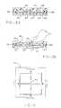
- FIG. 2Ais a cross-sectional side view of the touchpad assembly showing the various layers contained in the touchpad;
- FIG. 2Bis the assembly of FIG. 2A showing contact by a finger causing contact between the two semi-conductive layers;
- FIG. 3Ais a bottom view of the semi-conductive layer which controls the X direction signal of the touchpad
- FIG. 3Bis a top view of the semi-conductive layer which controls the Y direction signal of the touchpad
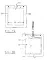
- FIG. 4is a top view of a graphic overlay containing markings to aid the user operating the chair.
- FIG. 5is an electrical touchpad interface schematic.
- the wheelchair having a touchpad for controlling speed and direction of the present inventioncan be any type of conventional, usual or ordinary powered wheelchair.
- FIG. 1is an example of a wheelchair 10 which can employ touchpad 20 used in the present invention.
- the wheelchaircan be powered by one or more batteries, D.C. current or any other alternative power source, which is capable of operating the touchpad and chair of the present invention.
- An optional battery compartment 14 for housing one or more batteriescan be seen in FIG. 1 , but any other element can be used to locate the batteries on the wheelchair.
- Any type of motor or motors, generally shown as 12can be employed to operably drive one or more wheels 16 of the wheelchair. Examples of such motors commonly used in the art can be classified as d.c. gear motors, brushless gear motors, or brushless gearless motors.
- Different types of wheel drivesfor example, front-wheel drive, mid-wheel-drive, rear-wheel drive, all-wheel drive, or four-wheel drive, can also be used in the present invention.
- the wheelchair of the present inventiongenerally contains a frame 40 upon which a seat 42 can be mounted.
- the seathas a seat back 44 and either or both can be stationary or have a fixed position, i.e. non or minimally adjustable. Tilt seats and/or seat backs, which may or may not maintain a constant center of gravity, can also be used.
- the seatmay be a reclining seat or both a tilting and reclining seat.
- the wheelchairmay have arms 46 , and footrest 48 .
- power wheelchairssuch as that shown in the drawings, different designs and embodiments, such as wheel sizes and locations can be utilized and the drawings are merely an example of one type of wheelchair.
- Touchpad 20 of the present inventioncomprises a touch or pressure controlled device capable of producing output voltage signals, which represent a point of contact along multiple axis directions in a field of two or more dimensions.
- the touchpad and the signals produced therebyare used to control the speed and direction of the wheelchair. Only a finger, nose, chin, toe, or other suitable object such as a pointer, etc. is needed to make contact or apply pressure to the sensor areas of the touchpad.
- FIG. 1Ashows touchpad 20 being operatively attached to mounting assembly 60 . This is only meant to be an example of one method for mounting the touchpad 20 to wheelchair 10 .
- Signal cable 62is operatively attached to touchpad 20 and is connected to a controller through controller attachment 64 .
- Extra option port 66can also be attached to signal cable 62 .
- Extra option port 66is a connection element which can allow touchpad 20 or a controller to be reprogrammed or diagnosed etc.
- the touchpad assemblycomprises a number of layers.
- a lower semi-conductive layer 22 as shown in FIGS. 2A and 2Bcomprise a flexible electrically conductive or semi-conductive film or membrane formed in any manner such as from a carbon ink spray, a thin metallic coating, a conductive or semi-conductive plastic, a semi-conductive rubber, or other coating.
- the lower semi-conductive layeris provided with two electrically lower conductive terminals or bussbars 30 and 31 , which are secured along the lengths of opposite film edges as can be seen in FIG. 3 B.
- Upper semi-conductive layer 28comprises a substantially identical electrically conductive or semi-conductive film or membrane which is also connected along each of two opposing edges to electrically conductive upper terminals or bussbars 32 and 33 as shown in FIG. 3 A.
- Upper layer 28is positioned on lower layer 22 so that lower terminals 30 and 31 are orthogonally oriented to upper terminals 32 and 33 of upper layer 28 when the faces of both films are positioned parallel to and coextensive with each other.
- the orthogonally oriented filmstogether define a two dimensional resistive field wherein electrical resistivity varies with distance from the bussbars or the elongated terminals.
- a spacer layer 26 as seen in FIG. 2Ais interposed around and/or between lower layer 22 and upper layer 28 generally about the perimeter thereof to prevent the lower and upper layers from contacting each other until a predetermined pressure is applied to the surface of the touchpad.
- spacer balls, spheres, dielectric dots 27 , or other non-active or nonconductive elementswhich serve to keep upper and lower semiconductive areas separated.
- a key aspect concerning the use of spacer balls, spheres, etc.is that they keep the two semi-conductive layers separated but yet are sufficiently distanced from one another so that upon applying pressure to the touchpad, semi-conductive sheets 22 and 28 are able to contact one another and thus complete an electrical circuit.
- the actuation force needed to contact upper and lower layersis generally of from about 0.25 to about 1.00 ounce.
- the average human fingerweighs about 0.75 ounces, easily allowing for finger operation of the touchpad.
- a first voltage V 1is applied across lower semiconductive layer or resistive film 22 between terminals 30 and 31
- a second voltage V 2is applied across upper semi-conductive upper layer or resistive film 28 between terminals 32 and 33 .
- the direction of current flow, and hence the direction of the voltage gradient in film 22is substantially orthogonally oriented with respect to the currently flow and voltage gradient in film 28 . Therefore, if sufficient pressure is applied to cause semi-conductive layers 22 and 28 to contact each other, then voltages which correspond to the X and Y coordinates of the contact location will be transmitted to those semi-conductive surfaces.
- the voltage measured at the point of contact between the filmsrepresent the Y coordinate as well as an X coordinate.
- the applied voltages V 1 and V 2may be either a.c. or d.c.; they can be simultaneously, sequentially or separately applied; and they may have the same or different waveforms since the output voltage for each coordinate is derived from a totally separate conductive surface. While not shown, both the X and Y axes can be separated in the touchpad, each axis having two semi-conductive layers, giving a total of four semiconductive layers for the touchpad. Additional semi-conductive layers can also exist if desired.
- the touchpad elementsare operatively connected to the power source of the wheelchair and drive means in order that the touchpad controls the speed and direction thereof.
- the touchpadis contained in an enclosure or housing, preferably rigid aluminum, which provides access to the active area of the touchpad surface but also protects the rest of the assembly.
- lower semi-conductive layer 22 and upper semi-conductive layer 28reside upon a flexible substrate 25 and 24 respectively which can be any suitable plastic or other non-conductive layer.
- a protective overlay- 36Positioned over the assembly comprising non-conductive layers 24 and 25 and semiconductive layers 22 and 28 is generally a protective overlay- 36 which protects the touchpad circuitry and seals out dust and water.
- the protective overlaycan contain a graphic overlay or template, which contains various markings or nomenclature, which serve to aid the person using the chair.
- FIG. 4One example of a graphic overlay is shown in FIG. 4 .
- Substrate 34can be a plastic, non-conductive adhesive or other layer, which is attached to the touchpad housing.
- the touchpad assemblyis generally square in shape and about 3.25 inches by 3.25 inches, but it can be any size or shape to meet the above noted objectives.
- the touchpadis preferably mounted on the housing so that it is in a horizontal position but it can be located in any position and/or it can be contoured to suit various needs of certain users.
- the touchpad assembly 20is operatively mounted on an arm 46 of the wheelchair, or at any other suitable location where it can comfortably be operated by the user of the chair.
- the userplaces a finger on the zero, neutral, or starting point of the touchpad as shown by 50 in FIG. 4 .
- the graphic overlay on the touchpadgenerally comprises an X, Y grid and the neutral point is located at the intersection of the X and Y axes, commonly the center of the pad.
- the filmflexes and a circuit is formed when lower semi-conductive layer 22 and upper semiconductive layer 28 contact one another. An example is shown in FIG. 3 B.
- the touchpad of the present inventionis a proportional speed and direction-controlling device.
- the further one's fingeris from the neutral point, the electrical resistivity is less with regard to that region and thus corresponds to a proportionally larger electrical voltage signal which is sent to the motor with regard to speed and direction.
- the wheelchairresponds and moves in a direction analogous to the finger movement on the touchpad and at a speed which corresponds to a distance from the neutral point of the touchpad. This is because the contact between the layers completes a circuit giving both X and Y coordinates which correspond proportionally to the direction and proportionally to the speed of the wheelchair.
- the chairmoves forward and at a speed proportionally or corresponding to the distance from the neutral point. If the user moves their finger in a positive X and Y direction, the chair moves forward at a given speed and to the right.
- the circuitis broken when pressure, i.e. usually the finger of the user, is removed and the film or membrane returns to its normally open or separated position.
- other gridscan also be utilized such as one obtained by rotating the XY axis 45°.
- the touchpadcan be programmed so that one does not have to start at a neutral point to activate the chair, where any contact creating a circuit on the touchpad can be used to activate the chair.
- the wheelchairhas two motors, each motor driving a separate wheel.
- a controller and operative circuitrywill divide the signal to drive the wheels at a faster rate the greater the pressure contact point is from the neutral point and also instruct one wheel to turn at a faster speed in order to change direction.
- the userif the user's finger or other pressure contacting element is lifted from the pad for more than a predetermined length of time, the user must reactivate the touchpad and wheelchair by starting from the neutral point.
- the amount of time from when contact is last made with the touchpad and when the touchpad must be reactivated from neutralis generally from about 0 or 1 milliseconds to about 1 second, desirably from about 100 to about 800 milliseconds, and preferably from about 200 to about 300 milliseconds.
- touchpad controlprovides the driver with tactile feedback, because the pad must be touched with direct contact in order to drive the chair.
- FIG. 5One particular electrical configuration for controlling and operating the touchpad assembly can be seen in FIG. 5 .
- the electronics of the touchpadare based on a micro controller that performs A/D conversions on the resistive touchpad and communicates thereto via a twisted pair network.
- touchpad interface electronics circuitwhich can generally be seen in FIG. 5 is as follows:
- U 5regulates the 15 VDC from the controller's power supply down to 5 VDC for use on the Touch Pad Interface Electronics PCB.
- Capacitors C 2 , C 3 , C 6 and C 7are used for filtering.
- U 3is the microcontroller integrated circuit (IC), for example a Motorola MC 143120 microcontroller. It is used for control of the A/D converter (U 2 ) driving the touchpad assembly 20 , as well as communications to the main controller via twisted pair network.
- C 4 , C 5 , X 1 , R 12 and R 9comprise the oscillator circuit for the microcontroller clock.
- D 1 , D 2 , R 8 , R 13 -R 18are provided for proper direct connection to serially communicate with the wheelchair motor control electronics.
- U 1is the reset circuit for the microcontroller IC (U 3 ). It resets the microcontroller 150 ms after the 5 VDC power supply has been established.
- U 2is the A/D converter used for reading the voltage levels from the touch pad. Even though AN 0 , AN 1 , AN 2 and AN 3 are all connected to the touchpad assembly 20 , only AN 0 and AN 1 are used for measurements.
- the A/D converter (U 2 )is controller by the microcontroller IC (U 3 ) using the SPI bus common to both the microcontroller IC and the A/D converter IC.
- R 4 -R 6are voltage divider resistors preventing the output from the touch pad, when activated, from going to either 0 VDC or 5 VDC.
- R 2 -R 3 Aare pull down resistors used to pull the outputs of the touch pad to 0 VDC when it is deactivated.
- the Speed readingis performed by the following sequence. IO 5 and IO 6 on U 3 are configured as outputs and IO 4 and IO 7 are configured as inputs (high impedance). Set IO 5 to high, 5 VDC and IO 6 as low, 0 VDC. The A/D conversion is then performed on AN 0 . If the touchpad is not pressed, there is no connection between the layers and AN 0 is essentially floating if not for R 3 A. R 3 A pulls the signal to 0 VDC. The A/D reading is then 0.
- IO 7 and IO 4 on U 3are configured as outputs and IO 5 and IO 6 are configured as inputs (high impedance). Set IO 7 to high, 5 VDC and IO 4 as low, 0 VDC. The A/D conversion is then performed on AN 1 . If the touchpad is not pressed, there is no connection between the layers and AN 1 is essentially floating if not for R 3 .
- R 3pulls the signal to 0 VDC. The A/D reading is then 0. If the touchpad is activated, then there is a connection between the layers and the voltage corresponding to the direction is seen at AN 1 . 2.5 VDC is mid scale i.e. neutral for direction. The voltage cannot go to either 5 VDC or 0 VDC due to the resister divider effects of R 4 and R 6 .
- the preferred controller of the present inventionis the MKIV controller available from Invacare Corporation of Cleveland, Ohio, but any other suitable controller known in the art may be utilized.
Landscapes
- Health & Medical Sciences (AREA)
- Life Sciences & Earth Sciences (AREA)
- Animal Behavior & Ethology (AREA)
- General Health & Medical Sciences (AREA)
- Public Health (AREA)
- Veterinary Medicine (AREA)
- Electric Propulsion And Braking For Vehicles (AREA)
Abstract
Description
Claims (10)
Priority Applications (1)
| Application Number | Priority Date | Filing Date | Title |
|---|---|---|---|
| US10/429,558US6926106B2 (en) | 1999-10-12 | 2003-05-05 | Wheelchair having speed and direction control touchpad |
Applications Claiming Priority (2)
| Application Number | Priority Date | Filing Date | Title |
|---|---|---|---|
| US41664799A | 1999-10-12 | 1999-10-12 | |
| US10/429,558US6926106B2 (en) | 1999-10-12 | 2003-05-05 | Wheelchair having speed and direction control touchpad |
Related Parent Applications (1)
| Application Number | Title | Priority Date | Filing Date |
|---|---|---|---|
| US41664799AContinuation | 1999-10-12 | 1999-10-12 |
Publications (2)
| Publication Number | Publication Date |
|---|---|
| US20030192728A1 US20030192728A1 (en) | 2003-10-16 |
| US6926106B2true US6926106B2 (en) | 2005-08-09 |
Family
ID=23650769
Family Applications (1)
| Application Number | Title | Priority Date | Filing Date |
|---|---|---|---|
| US10/429,558Expired - Fee RelatedUS6926106B2 (en) | 1999-10-12 | 2003-05-05 | Wheelchair having speed and direction control touchpad |
Country Status (5)
| Country | Link |
|---|---|
| US (1) | US6926106B2 (en) |
| EP (1) | EP1137385A1 (en) |
| AU (1) | AU753042B2 (en) |
| CA (1) | CA2342168A1 (en) |
| WO (1) | WO2001026599A1 (en) |
Cited By (18)
| Publication number | Priority date | Publication date | Assignee | Title |
|---|---|---|---|---|
| US20070050111A1 (en)* | 2005-08-31 | 2007-03-01 | Invacare Corp. | Method and apparatus for automated positioning of user support surfaces in power driven wheelchair |
| US20070055424A1 (en)* | 2005-08-31 | 2007-03-08 | Darryl Peters | Method and apparatus for setting or modifying programmable parameter in power driven wheelchair |
| WO2005094480A3 (en)* | 2004-03-23 | 2007-03-15 | Motiv Technology Inc | Power assist device |
| US20070074917A1 (en)* | 2005-08-31 | 2007-04-05 | Invacare Corp. | Adjustable mount for controller of power driven wheelchair |
| US20100108418A1 (en)* | 2005-05-30 | 2010-05-06 | Yoshisuke Kuramoto | Electric wheelchair |
| US7942445B2 (en) | 2006-06-19 | 2011-05-17 | Burke, Inc. | Personal mobility vehicle with anti-tip suspension |
| US20130090779A1 (en)* | 2011-10-07 | 2013-04-11 | Invacare Corporation | Proportional and non proportional drive control system |
| US8740240B1 (en)* | 2013-12-23 | 2014-06-03 | Maynard I. Merel | User-operated mobility apparatus |
| USD722286S1 (en) | 2012-07-31 | 2015-02-10 | Invacare International Sarl | Wheelchair frame |
| US8967672B2 (en)* | 2011-08-31 | 2015-03-03 | Mazda Motor Corporation | Vehicle-body structure of vehicle and manufacturing method of the same |
| US20150200665A1 (en)* | 2014-01-15 | 2015-07-16 | Kabushiki Kaisha Tokai Rika Denki Seisakusho | Operation device |
| USD735021S1 (en) | 2012-07-31 | 2015-07-28 | Invacare International Sarl | Caster wheel |
| USD754569S1 (en) | 2012-07-31 | 2016-04-26 | Invacare International Sarl | Wheelchair |
| US9348334B2 (en) | 2012-11-14 | 2016-05-24 | The Provost, Fellows, Foundation Scholars, and the Other Members of Board of the College of the Holy and Undivided Trinity of Queen Elizabeth Near Dublin College Green | Control interface for a semi-autonomous vehicle |
| USD765563S1 (en) | 2014-03-13 | 2016-09-06 | Invacare International Sarl | Wheelchair anti-tip |
| USD765839S1 (en) | 2014-05-15 | 2016-09-06 | Invacare International Sarl | Wheelchair table |
| WO2018237390A1 (en) | 2017-06-23 | 2018-12-27 | Invacare Corporation | METHODS AND SYSTEMS FOR CONFIGURING A TOUCH SCREEN OF A WHEELCHAIR ON THE BASIS OF THE USER'S PATHOLOGICAL STATUS |
| EP3197414B1 (en) | 2014-09-25 | 2019-07-10 | Sunrise Medical (US) LLC | Drive control system for powered wheelchair |
Families Citing this family (14)
| Publication number | Priority date | Publication date | Assignee | Title |
|---|---|---|---|---|
| PT103354B (en)* | 2005-09-21 | 2007-07-12 | Univ Do Minho | CONTROL SYSTEM FOR OMNIDIRECTIONAL WHEEL CHAIRS |
| SE0600839L (en)* | 2006-04-13 | 2007-10-14 | Permobil Ab | Control Device plate |
| US8244655B2 (en)* | 2007-05-01 | 2012-08-14 | University Of Florida Research Foundation, Inc. | Force-sensing orthotic electric device controller |
| US20090009466A1 (en)* | 2007-05-01 | 2009-01-08 | Hubbard Sandra L | Force-sensing orthotic electric device controller |
| DE202010007396U1 (en)* | 2010-05-31 | 2011-09-28 | Linrot Holding Ag | furniture drive |
| WO2012118561A1 (en)* | 2011-03-03 | 2012-09-07 | Flowersip, L.L.C. | Moveable steering and universal charger |
| WO2015089549A1 (en)* | 2013-12-17 | 2015-06-25 | Red Milawa Pty Ltd | Device and system for controlling a transport vehicle |
| US11294415B2 (en) | 2013-12-17 | 2022-04-05 | Red Milawa Pty Ltd | Device and system for controlling a transport vehicle |
| JP6814220B2 (en)* | 2016-09-06 | 2021-01-13 | Cyberdyne株式会社 | Mobility and mobility systems |
| CN107456621A (en)* | 2017-07-19 | 2017-12-12 | 种红侠 | Transfusion chair |
| JP7478506B2 (en)* | 2018-09-21 | 2024-05-07 | シャープ株式会社 | TRANSPORTATION SYSTEM, TRANSPORTATION METHOD, AND PROGRAM |
| CA3128095A1 (en)* | 2020-08-19 | 2022-02-19 | Red Milawa Pty Ltd. | Device and system for controlling a transport vehicle |
| US12226330B2 (en) | 2020-10-07 | 2025-02-18 | Jay Curtis Beavers | Systems, methods, and techniques for eye gaze control of seat and bed positioning |
| US12204687B2 (en) | 2023-04-11 | 2025-01-21 | Jay Curtis Beavers | Systems, methods, and techniques for safely controlling devices using eye gaze control |
Citations (39)
| Publication number | Priority date | Publication date | Assignee | Title |
|---|---|---|---|---|
| US3732389A (en)* | 1972-02-14 | 1973-05-08 | Litton Systems Inc | Touch entry switch array |
| US3814199A (en)* | 1972-08-21 | 1974-06-04 | Cleveland Machine Controls | Motor control apparatus adapted for use with a motorized vehicle |
| USRE28365E (en)* | 1970-04-30 | 1975-03-18 | Pressure-operated layered electrical switch and switch array | |
| US3895288A (en) | 1973-09-04 | 1975-07-15 | Stephen H Lampen | Touch controlled voltage-divider device |
| US3911215A (en)* | 1974-03-18 | 1975-10-07 | Elographics Inc | Discriminating contact sensor |
| US3916327A (en) | 1973-09-04 | 1975-10-28 | Stephen H Lampen | Output circuit for a voltage-divider device |
| US3968467A (en) | 1973-09-04 | 1976-07-06 | Stephen H. Lampen | Touch controlled voltage-divider device |
| CA1017823A (en) | 1975-04-11 | 1977-09-20 | Stephen H. Lampen | Touch controlled voltage-divider device |
| GB1505272A (en) | 1975-04-11 | 1978-03-30 | Lampen S | Voltage regulation apparatus |
| NL7908078A (en) | 1979-11-05 | 1981-06-01 | Herman Maurits Hoogstraat | Control panel for motorised wheel chair - has touch or pressure-sensitive sensors to control various motorised functions |
| US4293734A (en)* | 1979-02-23 | 1981-10-06 | Peptek, Incorporated | Touch panel system and method |
| US4323829A (en)* | 1980-07-28 | 1982-04-06 | Barry M. Fish | Capacitive sensor control system |
| US4444998A (en) | 1981-10-27 | 1984-04-24 | Spectra-Symbol Corporation | Touch controlled membrane for multi axis voltage selection |
| US4475235A (en)* | 1982-01-04 | 1984-10-02 | Rolm Corporation | Signature verification sensor |
| US4493219A (en) | 1982-08-02 | 1985-01-15 | Illinois Tool Works, Inc. | Force transducer |
| US4494105A (en) | 1982-03-26 | 1985-01-15 | Spectra-Symbol Corporation | Touch-controlled circuit apparatus for voltage selection |
| EP0135835A2 (en)* | 1983-09-24 | 1985-04-03 | PREH, Elektrofeinmechanische Werke Jakob Preh Nachf. GmbH & Co. | Flexible keyboard |
| US4523769A (en)* | 1982-09-14 | 1985-06-18 | Wright State University | Wheelchair and drive system therefor |
| US4529959A (en)* | 1983-01-31 | 1985-07-16 | Alps Electric Co., Ltd. | Input device |
| US4564079A (en)* | 1984-07-30 | 1986-01-14 | Koala Technologies Corporation | Digitizer pad |
| US4677417A (en) | 1985-12-06 | 1987-06-30 | Alps Electric Co., Ltd. | Tablet type input device |
| EP0235517A2 (en)* | 1986-02-28 | 1987-09-09 | SCHOELLER & CO. Elektrotechnische Fabrik GmbH & Co. | Layered push button switch |
| US4707570A (en)* | 1985-02-12 | 1987-11-17 | Ricoh Company, Ltd. | Manual information input device |
| JPH01230055A (en) | 1987-11-30 | 1989-09-13 | Mita Ind Co Ltd | Electrophotographic sensitive body |
| US4983786A (en) | 1990-01-17 | 1991-01-08 | The University Of British Columbia | XY velocity controller |
| US4990900A (en)* | 1987-10-01 | 1991-02-05 | Alps Electric Co., Ltd. | Touch panel |
| JPH03241623A (en)* | 1990-02-20 | 1991-10-28 | Fujitsu Ltd | Membrane keyboard |
| US5181030A (en) | 1989-12-28 | 1993-01-19 | Gunze Limited | Input system including resistance film touch panel and pushed position detecting device |
| US5199520A (en) | 1991-12-11 | 1993-04-06 | Sen Jung Chen | Wheeled chair |
| US5542690A (en)* | 1993-04-01 | 1996-08-06 | Forth Research, Inc. | Wheelchair for controlled environments |
| US5550339A (en)* | 1994-10-31 | 1996-08-27 | Cts Corporation | Variable speed tactile switch |
| US5648708A (en) | 1995-05-19 | 1997-07-15 | Power Concepts, Inc. | Force actuated machine controller |
| US5778996A (en)* | 1995-11-01 | 1998-07-14 | Prior; Ronald E. | Combination power wheelchair and walker |
| US5945929A (en)* | 1996-09-27 | 1999-08-31 | The Challenge Machinery Company | Touch control potentiometer |
| US6104317A (en)* | 1998-02-27 | 2000-08-15 | Motorola, Inc. | Data entry device and method |
| US6215478B1 (en)* | 1997-11-11 | 2001-04-10 | Fu-Kuo Yeh | High resolution finger input controlling device in an arbitrarily defined range |
| US6414671B1 (en)* | 1992-06-08 | 2002-07-02 | Synaptics Incorporated | Object position detector with edge motion feature and gesture recognition |
| US6424338B1 (en)* | 1999-09-30 | 2002-07-23 | Gateway, Inc. | Speed zone touchpad |
| US6529122B1 (en)* | 1999-12-10 | 2003-03-04 | Siemens Technology-To-Business Center, Llc | Tactile sensor apparatus and methods |
- 2000
- 2000-10-11AUAU80091/00Apatent/AU753042B2/ennot_activeCeased
- 2000-10-11EPEP00970761Apatent/EP1137385A1/ennot_activeWithdrawn
- 2000-10-11CACA002342168Apatent/CA2342168A1/ennot_activeAbandoned
- 2000-10-11WOPCT/US2000/028049patent/WO2001026599A1/ennot_activeApplication Discontinuation
- 2003
- 2003-05-05USUS10/429,558patent/US6926106B2/ennot_activeExpired - Fee Related
Patent Citations (39)
| Publication number | Priority date | Publication date | Assignee | Title |
|---|---|---|---|---|
| USRE28365E (en)* | 1970-04-30 | 1975-03-18 | Pressure-operated layered electrical switch and switch array | |
| US3732389A (en)* | 1972-02-14 | 1973-05-08 | Litton Systems Inc | Touch entry switch array |
| US3814199A (en)* | 1972-08-21 | 1974-06-04 | Cleveland Machine Controls | Motor control apparatus adapted for use with a motorized vehicle |
| US3895288A (en) | 1973-09-04 | 1975-07-15 | Stephen H Lampen | Touch controlled voltage-divider device |
| US3916327A (en) | 1973-09-04 | 1975-10-28 | Stephen H Lampen | Output circuit for a voltage-divider device |
| US3968467A (en) | 1973-09-04 | 1976-07-06 | Stephen H. Lampen | Touch controlled voltage-divider device |
| US3911215A (en)* | 1974-03-18 | 1975-10-07 | Elographics Inc | Discriminating contact sensor |
| GB1505272A (en) | 1975-04-11 | 1978-03-30 | Lampen S | Voltage regulation apparatus |
| CA1017823A (en) | 1975-04-11 | 1977-09-20 | Stephen H. Lampen | Touch controlled voltage-divider device |
| US4293734A (en)* | 1979-02-23 | 1981-10-06 | Peptek, Incorporated | Touch panel system and method |
| NL7908078A (en) | 1979-11-05 | 1981-06-01 | Herman Maurits Hoogstraat | Control panel for motorised wheel chair - has touch or pressure-sensitive sensors to control various motorised functions |
| US4323829A (en)* | 1980-07-28 | 1982-04-06 | Barry M. Fish | Capacitive sensor control system |
| US4444998A (en) | 1981-10-27 | 1984-04-24 | Spectra-Symbol Corporation | Touch controlled membrane for multi axis voltage selection |
| US4475235A (en)* | 1982-01-04 | 1984-10-02 | Rolm Corporation | Signature verification sensor |
| US4494105A (en) | 1982-03-26 | 1985-01-15 | Spectra-Symbol Corporation | Touch-controlled circuit apparatus for voltage selection |
| US4493219A (en) | 1982-08-02 | 1985-01-15 | Illinois Tool Works, Inc. | Force transducer |
| US4523769A (en)* | 1982-09-14 | 1985-06-18 | Wright State University | Wheelchair and drive system therefor |
| US4529959A (en)* | 1983-01-31 | 1985-07-16 | Alps Electric Co., Ltd. | Input device |
| EP0135835A2 (en)* | 1983-09-24 | 1985-04-03 | PREH, Elektrofeinmechanische Werke Jakob Preh Nachf. GmbH & Co. | Flexible keyboard |
| US4564079A (en)* | 1984-07-30 | 1986-01-14 | Koala Technologies Corporation | Digitizer pad |
| US4707570A (en)* | 1985-02-12 | 1987-11-17 | Ricoh Company, Ltd. | Manual information input device |
| US4677417A (en) | 1985-12-06 | 1987-06-30 | Alps Electric Co., Ltd. | Tablet type input device |
| EP0235517A2 (en)* | 1986-02-28 | 1987-09-09 | SCHOELLER & CO. Elektrotechnische Fabrik GmbH & Co. | Layered push button switch |
| US4990900A (en)* | 1987-10-01 | 1991-02-05 | Alps Electric Co., Ltd. | Touch panel |
| JPH01230055A (en) | 1987-11-30 | 1989-09-13 | Mita Ind Co Ltd | Electrophotographic sensitive body |
| US5181030A (en) | 1989-12-28 | 1993-01-19 | Gunze Limited | Input system including resistance film touch panel and pushed position detecting device |
| US4983786A (en) | 1990-01-17 | 1991-01-08 | The University Of British Columbia | XY velocity controller |
| JPH03241623A (en)* | 1990-02-20 | 1991-10-28 | Fujitsu Ltd | Membrane keyboard |
| US5199520A (en) | 1991-12-11 | 1993-04-06 | Sen Jung Chen | Wheeled chair |
| US6414671B1 (en)* | 1992-06-08 | 2002-07-02 | Synaptics Incorporated | Object position detector with edge motion feature and gesture recognition |
| US5542690A (en)* | 1993-04-01 | 1996-08-06 | Forth Research, Inc. | Wheelchair for controlled environments |
| US5550339A (en)* | 1994-10-31 | 1996-08-27 | Cts Corporation | Variable speed tactile switch |
| US5648708A (en) | 1995-05-19 | 1997-07-15 | Power Concepts, Inc. | Force actuated machine controller |
| US5778996A (en)* | 1995-11-01 | 1998-07-14 | Prior; Ronald E. | Combination power wheelchair and walker |
| US5945929A (en)* | 1996-09-27 | 1999-08-31 | The Challenge Machinery Company | Touch control potentiometer |
| US6215478B1 (en)* | 1997-11-11 | 2001-04-10 | Fu-Kuo Yeh | High resolution finger input controlling device in an arbitrarily defined range |
| US6104317A (en)* | 1998-02-27 | 2000-08-15 | Motorola, Inc. | Data entry device and method |
| US6424338B1 (en)* | 1999-09-30 | 2002-07-23 | Gateway, Inc. | Speed zone touchpad |
| US6529122B1 (en)* | 1999-12-10 | 2003-03-04 | Siemens Technology-To-Business Center, Llc | Tactile sensor apparatus and methods |
Cited By (47)
| Publication number | Priority date | Publication date | Assignee | Title |
|---|---|---|---|---|
| WO2005094480A3 (en)* | 2004-03-23 | 2007-03-15 | Motiv Technology Inc | Power assist device |
| US8210295B2 (en)* | 2005-05-30 | 2012-07-03 | Yoshisuke Kuramoto | Electric wheelchair |
| US20100108418A1 (en)* | 2005-05-30 | 2010-05-06 | Yoshisuke Kuramoto | Electric wheelchair |
| US8145373B2 (en) | 2005-08-31 | 2012-03-27 | Invacare Corporation | Method and apparatus for programming parameters of a power driven wheelchair for a plurality of drive settings |
| US9456942B2 (en) | 2005-08-31 | 2016-10-04 | Invacare Corporation | Method and apparatus for setting or modifying programmable parameter in power driven wheelchair |
| US20070056780A1 (en)* | 2005-08-31 | 2007-03-15 | Invacare Corporation | Method and apparatus for setting or modifying programmable parameters in power driven wheelchair |
| US20070067072A1 (en)* | 2005-08-31 | 2007-03-22 | Invacare Corporation | Method and apparatus for programming parameters of a power driven wheelchair for a plurality of drive settings |
| US20070074917A1 (en)* | 2005-08-31 | 2007-04-05 | Invacare Corp. | Adjustable mount for controller of power driven wheelchair |
| US7403844B2 (en) | 2005-08-31 | 2008-07-22 | Invacare Corporation | Method and apparatus for programming parameters of a power driven wheelchair for a plurality of drive settings |
| US20080249694A1 (en)* | 2005-08-31 | 2008-10-09 | Invacare Corporation | Method and Apparatus for Programming Parameters of a Power Driven Wheelchair for a Plurality of Drive Settings |
| US20070056781A1 (en)* | 2005-08-31 | 2007-03-15 | Invacare Corporation | Power driven wheelchair |
| US10130534B2 (en) | 2005-08-31 | 2018-11-20 | Invacare Corporation | Method and apparatus for automated positioning of user support surfaces in power driven wheelchair |
| US8065051B2 (en) | 2005-08-31 | 2011-11-22 | Invacare Corporation | Context-sensitive help for display device associated with power driven wheelchair |
| US8073585B2 (en) | 2005-08-31 | 2011-12-06 | Invacare Corporation | Method and apparatus for setting or modifying programmable parameters in power driven wheelchair |
| US8073588B2 (en) | 2005-08-31 | 2011-12-06 | Invacare Corporation | Method and apparatus for setting or modifying programmable parameter in power driven wheelchair |
| US8127875B2 (en)* | 2005-08-31 | 2012-03-06 | Invacare Corporation | Power driven wheelchair |
| US9084705B2 (en) | 2005-08-31 | 2015-07-21 | Invacare Corporation | Method and apparatus for setting or modifying programmable parameters in power driven wheelchair |
| US20070056782A1 (en)* | 2005-08-31 | 2007-03-15 | Invacare Corporation | Context-sensitive help for display device associated with power driven wheelchair |
| US20070050111A1 (en)* | 2005-08-31 | 2007-03-01 | Invacare Corp. | Method and apparatus for automated positioning of user support surfaces in power driven wheelchair |
| US8646551B2 (en) | 2005-08-31 | 2014-02-11 | Invacare Corporation | Power driven wheelchair |
| US8437899B2 (en) | 2005-08-31 | 2013-05-07 | Invacare Corporation | Method and apparatus for programming parameters of a power driven wheelchair for a plurality of drive settings |
| US8285440B2 (en) | 2005-08-31 | 2012-10-09 | Invacare Corporation | Method and apparatus for setting or modifying programmable parameters in power driven wheelchair |
| US11071665B2 (en) | 2005-08-31 | 2021-07-27 | Invacare Corporation | Method and apparatus for setting or modifying programmable parameter in power driven wheelchair |
| US8793032B2 (en) | 2005-08-31 | 2014-07-29 | Invacare Corporation | Method and apparatus for setting or modifying programmable parameter in power driven wheelchair |
| US9522091B2 (en) | 2005-08-31 | 2016-12-20 | Invacare Corporation | Method and apparatus for automated positioning of user support surfaces in power driven wheelchair |
| US20070055424A1 (en)* | 2005-08-31 | 2007-03-08 | Darryl Peters | Method and apparatus for setting or modifying programmable parameter in power driven wheelchair |
| US8977431B2 (en) | 2005-08-31 | 2015-03-10 | Invacare Corporation | Method and apparatus for setting or modifying programmable parameter in power driven wheelchair |
| US7942445B2 (en) | 2006-06-19 | 2011-05-17 | Burke, Inc. | Personal mobility vehicle with anti-tip suspension |
| US8967672B2 (en)* | 2011-08-31 | 2015-03-03 | Mazda Motor Corporation | Vehicle-body structure of vehicle and manufacturing method of the same |
| US20130090779A1 (en)* | 2011-10-07 | 2013-04-11 | Invacare Corporation | Proportional and non proportional drive control system |
| USD722286S1 (en) | 2012-07-31 | 2015-02-10 | Invacare International Sarl | Wheelchair frame |
| USD735021S1 (en) | 2012-07-31 | 2015-07-28 | Invacare International Sarl | Caster wheel |
| USD749019S1 (en) | 2012-07-31 | 2016-02-09 | Invacare International Sarl | Wheelchair frame |
| USD754569S1 (en) | 2012-07-31 | 2016-04-26 | Invacare International Sarl | Wheelchair |
| US9348334B2 (en) | 2012-11-14 | 2016-05-24 | The Provost, Fellows, Foundation Scholars, and the Other Members of Board of the College of the Holy and Undivided Trinity of Queen Elizabeth Near Dublin College Green | Control interface for a semi-autonomous vehicle |
| US8740240B1 (en)* | 2013-12-23 | 2014-06-03 | Maynard I. Merel | User-operated mobility apparatus |
| US9391611B2 (en)* | 2014-01-15 | 2016-07-12 | Kabushiki Kaisha Tokai Rika Denki Seisakusho | Operation device |
| JP2015133045A (en)* | 2014-01-15 | 2015-07-23 | 株式会社東海理化電機製作所 | Operation device |
| US20150200665A1 (en)* | 2014-01-15 | 2015-07-16 | Kabushiki Kaisha Tokai Rika Denki Seisakusho | Operation device |
| USD765563S1 (en) | 2014-03-13 | 2016-09-06 | Invacare International Sarl | Wheelchair anti-tip |
| USD765562S1 (en) | 2014-03-13 | 2016-09-06 | Invacare International Sarl | Wheelchair armrest |
| USD770334S1 (en) | 2014-03-13 | 2016-11-01 | Invacare International Sarl | Wheelchair frame |
| USD770946S1 (en) | 2014-03-13 | 2016-11-08 | Invacare International Sarl | Wheelchair frame |
| USD765839S1 (en) | 2014-05-15 | 2016-09-06 | Invacare International Sarl | Wheelchair table |
| EP3197414B1 (en) | 2014-09-25 | 2019-07-10 | Sunrise Medical (US) LLC | Drive control system for powered wheelchair |
| US11096844B2 (en) | 2014-09-25 | 2021-08-24 | Sunrise Medical (Us) Llc | Drive control system for powered wheelchair |
| WO2018237390A1 (en) | 2017-06-23 | 2018-12-27 | Invacare Corporation | METHODS AND SYSTEMS FOR CONFIGURING A TOUCH SCREEN OF A WHEELCHAIR ON THE BASIS OF THE USER'S PATHOLOGICAL STATUS |
Also Published As
| Publication number | Publication date |
|---|---|
| AU8009100A (en) | 2001-04-23 |
| WO2001026599A1 (en) | 2001-04-19 |
| EP1137385A1 (en) | 2001-10-04 |
| CA2342168A1 (en) | 2001-04-19 |
| US20030192728A1 (en) | 2003-10-16 |
| AU753042B2 (en) | 2002-10-03 |
Similar Documents
| Publication | Publication Date | Title |
|---|---|---|
| US6926106B2 (en) | Wheelchair having speed and direction control touchpad | |
| US5648708A (en) | Force actuated machine controller | |
| US8539627B2 (en) | Body position and pressure control apparatus | |
| KR100954377B1 (en) | Tactile Sensors and Tactile Sensor Applications | |
| WO1993014386A1 (en) | Distribution-type touch sensor | |
| Wang et al. | The Personal Mobility and Manipulation Appliance (PerMMA): A robotic wheelchair with advanced mobility and manipulation | |
| WO2016210173A1 (en) | Sensor systems integrated with steering wheels | |
| EP3197414B1 (en) | Drive control system for powered wheelchair | |
| US6422747B2 (en) | Movable type x-ray photographing apparatus | |
| JP5448752B2 (en) | Input interface device | |
| CN101258389B (en) | tactile sensor and tactile sensor application device | |
| TWI549668B (en) | Wheelchair control system and control method thereof | |
| JP3727642B1 (en) | Tactile sensor and tactile sensor application device | |
| KR100485495B1 (en) | A powered wheelchair control sensor by using head motion and implemented system for spinal injured persons | |
| JP3796531B2 (en) | Control signal input method and apparatus for mobile equipment such as electric wheelchair | |
| US20240238138A1 (en) | Apparatus and method for proportional control of power wheelchair or mobility device | |
| JP3727487B2 (en) | Position input operation device and chair type massage machine | |
| KR20140110402A (en) | Control device using sensor and move assist system having the same | |
| Patil et al. | Wheelchair Control Using IoT and Fall Detection Mechanism Check for updates | |
| CN118068963B (en) | An airbag type dynamic force tactile sensing device | |
| TWM443521U (en) | Wheelchair drive device featuring rotation speed control | |
| JP2001070355A (en) | Electric wheelchair control device using pressure sensitive control switch device | |
| Lee et al. | Three-Axis Pneumatic Haptic Display for the Mechanical and Thermal Stimulation of a Human Finger Pad. Actuators 2021, 10, 60 | |
| Patil et al. | Wheelchair Control Using IoT and Fall Detection Mechanism | |
| JP2003337645A (en) | Tactile device |
Legal Events
| Date | Code | Title | Description |
|---|---|---|---|
| AS | Assignment | Owner name:NATIONAL CITY BANK, AS MULTICURRENCY COLLATERAL AG Free format text:NOTICE OF GRANT OF SECURITY INTEREST;ASSIGNOR:INVACARE CORPORATION;REEL/FRAME:019009/0134 Effective date:20070212 | |
| FPAY | Fee payment | Year of fee payment:4 | |
| AS | Assignment | Owner name:PNC BANK, NATIONAL ASSOCIATION, PENNSYLVANIA Free format text:SECURITY AGREEMENT;ASSIGNORS:INVACARE CORPORATION;ADAPTIVE SWITCH LABORATORIES, INC.;THE AFTERMARKET GROUP, INC.;AND OTHERS;REEL/FRAME:025473/0311 Effective date:20101028 | |
| REMI | Maintenance fee reminder mailed | ||
| LAPS | Lapse for failure to pay maintenance fees | ||
| STCH | Information on status: patent discontinuation | Free format text:PATENT EXPIRED DUE TO NONPAYMENT OF MAINTENANCE FEES UNDER 37 CFR 1.362 | |
| FP | Lapsed due to failure to pay maintenance fee | Effective date:20130809 | |
| AS | Assignment | Owner name:INVACARE CORPORATION, OHIO Free format text:RELEASE BY SECURED PARTY;ASSIGNOR:PNC BANK, NATIONAL ASSOCIATION;REEL/FRAME:063638/0261 Effective date:20230505 | |
| AS | Assignment | Owner name:INVACARE HCS, LLC, OHIO Free format text:RELEASE BY SECURED PARTY;ASSIGNOR:PNC BANK, NATIONAL ASSOCIATION;REEL/FRAME:063668/0679 Effective date:20230505 Owner name:INVACARE FLORIDA HOLDINGS, LLC, OHIO Free format text:RELEASE BY SECURED PARTY;ASSIGNOR:PNC BANK, NATIONAL ASSOCIATION;REEL/FRAME:063668/0679 Effective date:20230505 Owner name:GARDEN CITY MEDICAL INC., OHIO Free format text:RELEASE BY SECURED PARTY;ASSIGNOR:PNC BANK, NATIONAL ASSOCIATION;REEL/FRAME:063668/0679 Effective date:20230505 Owner name:FREEDOM DESIGNS, INC., OHIO Free format text:RELEASE BY SECURED PARTY;ASSIGNOR:PNC BANK, NATIONAL ASSOCIATION;REEL/FRAME:063668/0679 Effective date:20230505 Owner name:ROADRUNNER MOBILITY, INCORPORATED, OHIO Free format text:RELEASE BY SECURED PARTY;ASSIGNOR:PNC BANK, NATIONAL ASSOCIATION;REEL/FRAME:063668/0679 Effective date:20230505 Owner name:KUSCHALL, INC., OHIO Free format text:RELEASE BY SECURED PARTY;ASSIGNOR:PNC BANK, NATIONAL ASSOCIATION;REEL/FRAME:063668/0679 Effective date:20230505 Owner name:INVAMEX HOLDINGS LLC, OHIO Free format text:RELEASE BY SECURED PARTY;ASSIGNOR:PNC BANK, NATIONAL ASSOCIATION;REEL/FRAME:063668/0679 Effective date:20230505 Owner name:INVACARE SUPPLY GROUP, INC., OHIO Free format text:RELEASE BY SECURED PARTY;ASSIGNOR:PNC BANK, NATIONAL ASSOCIATION;REEL/FRAME:063668/0679 Effective date:20230505 Owner name:INVACARE INTERNATIONAL CORPORATION, OHIO Free format text:RELEASE BY SECURED PARTY;ASSIGNOR:PNC BANK, NATIONAL ASSOCIATION;REEL/FRAME:063668/0679 Effective date:20230505 Owner name:INVACARE HOLDINGS, LLC, OHIO Free format text:RELEASE BY SECURED PARTY;ASSIGNOR:PNC BANK, NATIONAL ASSOCIATION;REEL/FRAME:063668/0679 Effective date:20230505 Owner name:INVACARE FLORIDA CORPORATION, OHIO Free format text:RELEASE BY SECURED PARTY;ASSIGNOR:PNC BANK, NATIONAL ASSOCIATION;REEL/FRAME:063668/0679 Effective date:20230505 Owner name:INVACARE CREDIT CORPORATION, OHIO Free format text:RELEASE BY SECURED PARTY;ASSIGNOR:PNC BANK, NATIONAL ASSOCIATION;REEL/FRAME:063668/0679 Effective date:20230505 Owner name:INVACARE CONTINUING CARE, INC., OHIO Free format text:RELEASE BY SECURED PARTY;ASSIGNOR:PNC BANK, NATIONAL ASSOCIATION;REEL/FRAME:063668/0679 Effective date:20230505 Owner name:INVACARE CANADIAN HOLDINGS, LLC, OHIO Free format text:RELEASE BY SECURED PARTY;ASSIGNOR:PNC BANK, NATIONAL ASSOCIATION;REEL/FRAME:063668/0679 Effective date:20230505 Owner name:INVACARE CANADIAN HOLDINGS, INC., OHIO Free format text:RELEASE BY SECURED PARTY;ASSIGNOR:PNC BANK, NATIONAL ASSOCIATION;REEL/FRAME:063668/0679 Effective date:20230505 Owner name:THE HELIXX GROUP, INC., OHIO Free format text:RELEASE BY SECURED PARTY;ASSIGNOR:PNC BANK, NATIONAL ASSOCIATION;REEL/FRAME:063668/0679 Effective date:20230505 Owner name:FAMILY MEDICAL SUPPLY LLC, OHIO Free format text:RELEASE BY SECURED PARTY;ASSIGNOR:PNC BANK, NATIONAL ASSOCIATION;REEL/FRAME:063668/0679 Effective date:20230505 Owner name:CHAMPION MANUFACTURING INC., OHIO Free format text:RELEASE BY SECURED PARTY;ASSIGNOR:PNC BANK, NATIONAL ASSOCIATION;REEL/FRAME:063668/0679 Effective date:20230505 Owner name:CENTRALIZED MEDICAL EQUIPMENT LLC, OHIO Free format text:RELEASE BY SECURED PARTY;ASSIGNOR:PNC BANK, NATIONAL ASSOCIATION;REEL/FRAME:063668/0679 Effective date:20230505 Owner name:ALTIMATE MEDICAL, INC., OHIO Free format text:RELEASE BY SECURED PARTY;ASSIGNOR:PNC BANK, NATIONAL ASSOCIATION;REEL/FRAME:063668/0679 Effective date:20230505 Owner name:THE AFTERMARKET GROUP, INC., OHIO Free format text:RELEASE BY SECURED PARTY;ASSIGNOR:PNC BANK, NATIONAL ASSOCIATION;REEL/FRAME:063668/0679 Effective date:20230505 Owner name:ADAPTIVE SWITCH LABORATORIES, INC., OHIO Free format text:RELEASE BY SECURED PARTY;ASSIGNOR:PNC BANK, NATIONAL ASSOCIATION;REEL/FRAME:063668/0679 Effective date:20230505 Owner name:INVACARE CORPORATION, OHIO Free format text:RELEASE BY SECURED PARTY;ASSIGNOR:PNC BANK, NATIONAL ASSOCIATION;REEL/FRAME:063668/0679 Effective date:20230505 |