US6926099B2 - Drill out bi-center bit and method for using same - Google Patents
Drill out bi-center bit and method for using sameDownload PDFInfo
- Publication number
- US6926099B2 US6926099B2US10/397,566US39756603AUS6926099B2US 6926099 B2US6926099 B2US 6926099B2US 39756603 AUS39756603 AUS 39756603AUS 6926099 B2US6926099 B2US 6926099B2
- Authority
- US
- United States
- Prior art keywords
- section
- cutter assemblies
- bit
- center bit
- depth
- Prior art date
- Legal status (The legal status is an assumption and is not a legal conclusion. Google has not performed a legal analysis and makes no representation as to the accuracy of the status listed.)
- Expired - Lifetime, expires
Links
- 238000000034methodMethods0.000titleclaimsabstractdescription17
- 230000000712assemblyEffects0.000claimsabstractdescription42
- 238000000429assemblyMethods0.000claimsabstractdescription42
- 229910003460diamondInorganic materials0.000claimsdescription10
- 239000010432diamondSubstances0.000claimsdescription10
- 238000007790scrapingMethods0.000claimsdescription6
- 230000002708enhancing effectEffects0.000claims1
- 239000004568cementSubstances0.000abstractdescription11
- 238000005553drillingMethods0.000description18
- 239000000463materialSubstances0.000description10
- 238000013461designMethods0.000description5
- 239000012530fluidSubstances0.000description5
- UONOETXJSWQNOL-UHFFFAOYSA-Ntungsten carbideChemical compound[W+]#[C-]UONOETXJSWQNOL-UHFFFAOYSA-N0.000description3
- 230000015572biosynthetic processEffects0.000description2
- 238000004891communicationMethods0.000description2
- 238000005755formation reactionMethods0.000description2
- 230000035515penetrationEffects0.000description2
- 229910000881Cu alloyInorganic materials0.000description1
- 229910001209Low-carbon steelInorganic materials0.000description1
- 229910000831SteelInorganic materials0.000description1
- 239000011230binding agentSubstances0.000description1
- 238000010348incorporationMethods0.000description1
- 229910052500inorganic mineralInorganic materials0.000description1
- 238000003780insertionMethods0.000description1
- 230000037431insertionEffects0.000description1
- 239000011159matrix materialSubstances0.000description1
- 239000011707mineralSubstances0.000description1
- 238000012986modificationMethods0.000description1
- 230000004048modificationEffects0.000description1
- 230000008707rearrangementEffects0.000description1
- 238000011084recoveryMethods0.000description1
- 239000010959steelSubstances0.000description1
- 238000006467substitution reactionMethods0.000description1
- XLYOFNOQVPJJNP-UHFFFAOYSA-NwaterSubstancesOXLYOFNOQVPJJNP-UHFFFAOYSA-N0.000description1
Images


Classifications
- E—FIXED CONSTRUCTIONS
- E21—EARTH OR ROCK DRILLING; MINING
- E21B—EARTH OR ROCK DRILLING; OBTAINING OIL, GAS, WATER, SOLUBLE OR MELTABLE MATERIALS OR A SLURRY OF MINERALS FROM WELLS
- E21B10/00—Drill bits
- E21B10/26—Drill bits with leading portion, i.e. drill bits with a pilot cutter; Drill bits for enlarging the borehole, e.g. reamers
- E21B10/265—Bi-center drill bits, i.e. an integral bit and eccentric reamer used to simultaneously drill and underream the hole
Definitions
- the present inventionrelates in general to the field of oil and gas drilling and, in particular, to a drill out bi-center bit and a method for using the same.
- a bi-center bitis an undersized drill bit with a large eccentric cutting structure located off-center above a smaller pilot drill bit that is centered axially with the drill collars.
- the bi-center bitis sized so that while being run into the hole, the pilot bit is pushed to one side to allow the tool to pass through the inside of the casing. Once at the bottom of the hole, though, the pilot bit then acts as a centered pivot point for the eccentric cutting structure above, which generates a hole larger in diameter than the inside diameter of the casing through which it passed.
- bi-center bitssuffer from one or more limitations.
- One such limitationis the inability of many bi-center bits to drill out cement or casing shoes. This is due to the fact that when the bit is inside a casing, the pilot section of the bit tends to rotate around the center of the drill string, causing the gauge cutters to engage the casing. This damages both the cutters and the casing. Additionally, since the center of the pilot bit is aligned with the drill string, the bit also tends to rotate off-center when inside the casing. This can cause damage to the cutters on the leading face of the bi-center drill bit. The extent of this damage may be further increased when a directional drilling bottom hole assembly is attached to the drill string just above the bit.
- cutters placed in the center of the bitmay rotate backward (i.e., opposite their cutting faces) when the bit is inside a casing. This backward rotation prevents efficient cutting action, and when the cutters contact the casing, may result in damage to the cutters.
- a drill out bi-center bit and a method for using the sameoffer the ability to drill out cement and casing shoes, and increased stability.
- the bi-center bitcomprises a bit body having a first end operable to be coupled with a drill string, a second end including a pilot section, and an eccentric reamer section intermediate the first and second ends.
- a first plurality of cutter assembliesis disposed upon the exterior surface of both the pilot section, while a second plurality of cutter assemblies is disposed upon the reamer section.
- a plurality of recessed cutter assembliesis also disposed upon the pilot section, such that the recessed cutter assemblies are located within a radius beginning at a central axis of the pilot section and terminating at a central axis of the reamer section and are recessed with respect to a lower surface of the pilot.
- Another technical advantage of particular embodiments of the present inventionis a bi-center drill bit that does not require specialized center cutters that can only be used in the drill out mode. Because of this, the center cutters of the bi-center bit may be placed more efficiently, allowing a better utilization of the center cutters.
- Yet another technical advantage of particular embodiments of the present inventionis that it allows many choices of bit profile, as long as the cutters outside the casing centerline precede the center cutters in the cement drilling, or drill-out, operation. This allows a designer to select bit profiles to better suit drilling conditions.
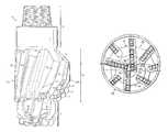
- FIG. 1illustrates an isometric view of a bi-center bit having a recessed area on its pilot section in accordance with a particular embodiment of the present invention
- FIG. 2illustrates a side view of the bi-center bit shown in FIG. 1 ;
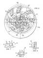
- FIG. 3illustrates a face view of a bi-center bit having a recessed area on its pilot section, as it would be positioned within a casing;
- FIG. 4illustrates a face view of the bi-center bit shown in FIG. 3 as it would be positioned during hole enlargement
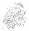
- FIG. 5illustrates a cut-away side view of a bi-center bit having a recessed area on its pilot section
- FIG. 6illustrates a face view of a bi-center bit having smooth bearing areas and depth of cut limiters on its reamer section
- FIG. 7illustrates a side view of a depth of cut limiter employed in a particular embodiment of a bi-center bit
- FIG. 8illustrates a top view of the depth of cut limiter shown in FIG. 7 ;
- FIG. 9illustrates a front view of the depth of cut limiter shown in FIG. 7 , in contact with a casing wall.
- FIG. 1illustrates an isometric view of bi-center bit 10 in accordance with a particular embodiment of the present invention.
- Bi-center bit 10is a drill bit used for drilling bore holes into the earth for mineral, oil, and/or gas recovery.
- bi-center bit 10is a bi-center drill bit designed to drill out the cement and other material inside a casing. After drilling out the cement and other material, the bi-center bit 10 drills a full bore hole with a diameter greater than the inner diameter of the casing(s) through which it passed.
- bi-center bit 10is configured with non-drilling bearing elements that contact the casing when the bit is drilling the cement, and prevent the gauge cutting elements of bi-center bit 10 from contacting the casing.
- Bi-center bit 10also includes a recessed area on the center of the pilot section that prevents reverse scraping of the cutting elements when drilling both the cement and the formation.
- bi-center bit 10includes a generally elongate bit body having a pilot section 11 disposed at its first end and a threaded region 13 , adapted to receive a drill string or other well tool, disposed at its second end.
- Bi-center bit 10may be constructed of a mild steel core attached to a steel shank, with a body made of tungsten carbide matrix with a copper alloy binder. However, it should be recognized that bi-center bit 10 may be constructed using one or more of a variety of materials.
- pilot section 11is down-hole from threaded region 13 . In this installed position, threaded region 13 is coupled with a drill string such that bi-center bit 10 is in fluid communication with the drill string during drilling operation.
- reamer section 12is positioned above and off-center from pilot section 11 .
- reamer section 12rotates about a central axis that coincides with the central axis of the casing. This central axis is offset from the central axis of the pilot section.
- the central axis of the casingmay be referred to as the central axis of the reamer section 12 .
- pilot section 11 , reamer section 12 , and threaded end 13 of bi-center bit 10are configured so that while being run into a well bore, pilot section 11 is pushed to one side to allow the bit 10 to pass through the inside of the casing. Once bi-center bit 10 is through the casing or well bore, pilot section 11 then acts as a centered pivot point for eccentric reamer section 12 above it. During operation, reamer section 12 pivots generally around a central axis of pilot bit 11 , generating a hole larger in diameter than the inside diameter of the casing through which it passed.
- ribs 16Disposed on pilot section 11 and reamer section 12 are a plurality of ribs 16 . On each of these ribs 16 , a plurality of cutter assemblies 17 are disposed. These cutter assemblies 17 include cutting elements made from polycrystalline diamond compact (PDC) or other suitable materials, which may brazed to the tungsten carbide bit body. Disposed between the ribs 16 are a plurality of grooves or flutes 19 . These grooves or flutes 19 accommodate the flow of drilling fluid, water, and/or debris up-hole from bi-center bit 10 during operation.
- PDCpolycrystalline diamond compact
- Bi-center bit 10also includes a number of circulation ports or nozzles 18 located near its central axis. These nozzles 18 connect with the center of the bit body and distribute the above-mentioned drilling fluid, which is pumped down the drill string, into the bit body, and out into the well bore.
- FIG. 2illustrates a side view of bi-center bit 10 as it would be oriented in a well bore.
- pilot section 11is located down-hole from threaded region 13 .
- the ribs 16 on reamer section 12extend further out from the central, longitudinal axis of the bit body on one side, side 20 A, of the reamer than the other, side 20 B.
- reamer section 12pivots generally around a central axis of pilot section 11 .
- side 20 Aalso known as the full-hole gauge contact region, comes in contact with the wall of the well bore and may be used to enlarge the diameter of the well bore.
- the bi-center bitBefore the bi-center bit can be used to enlarge the diameter of a well bore, though, it must first pass through a casing.
- a typical bi-center bitWhen a typical bi-center bit is rotated in a casing, the bit is constrained such that it must rotate about the center of the casing rather than the center of the drill string. If the bit rides smoothly on the casing wall, some cutter assemblies in the center of the pilot section rotate in the opposite direction of their cutting face. This type of rotation can damage the cutters due to reverse scraping. However, if the bit does not ride smoothly on the casing, the outer cutters and casing can also be damaged. Once through the casing, the bi-center bit is no longer constrained by the casing and is free to rotate about the central axis of the pilot section, which is typically coaxial with the central axis of the drill string.
- FIGS. 3 and 4An example of such a bi-center bit having a recessed area in the pilot is shown in FIGS. 3 and 4 .
- FIGS. 3 and 4illustrate face views of bi-center bit 30 in accordance with a particular embodiment of the present invention.
- Bi-center bit 30similar to other bi-center bits, typically rotates around one of two centers of rotation: central axis 33 of the pilot section 31 , or second central axis 34 of the reamer section 32 .
- bi-center bit 30is shown as it would be used to drill out a casing 38 .
- bi-center bit 30rotates around central axis 34 of reamer section 32 .
- bi-center bit 30rotates counter-clockwise when viewed from below. Due to this rotation about the central axis 34 of the reamer section 32 , some of the cutters on pilot section 31 (illustrated by cutters 37 a and 37 b ) rotate opposite the normal cutting direction of the cutters (i.e., opposite the direction of their cutting faces). On a typical bi-center bit, this backward rotation of the cutters would result in excessive wear and damage to the cutters due to reverse scraping.
- recessed area 35which is a circular area centered at central axis 33 of pilot section 31 and extending to central axis 34 of reamer section 32 , are recessed with respect to a lower surface of pilot section 31 . In other words, they are recessed into the tip of pilot section 31 . Due to the fact that they are recessed into pilot section 31 , the cutters within recessed area 35 are prevented from coming in contact with the material to be drilled when bi-center bit 30 is used to drill out a casing. Because of this, there is less likelihood of the cutters being damaged or drilling operations being slowed due to the backward rotation of the cutters.
- bi-center bit 30After passing through the casing, bi-center bit 30 may be used to enlarge a well bore.
- FIG. 4illustrates bi-center bit 30 as it would be used for such a full-hole operation.
- bi-center bit 30still rotates counter-clockwise; however, bi-center bit 30 now rotates around central axis 33 of pilot section 31 (rather than central axis 34 of reamer section 32 ).
- the directional arrowsunlike drill-out operation, during full-hole operation all of the cutters on bi-center bit 30 rotate with their cutting faces forward, even those cutters that are recessed into area 35 on the pilot section 31 . Because of this forward rotation, the cutters within area 35 may be used for cutting during full-hole operation, even though they were prevented from cutting during drill-out.
- This ability to use the recessed cutters in full-hole operationis yet another advantage of particular embodiments of the present invention.
- FIG. 5illustrates a cut-away side view of bi-center bit 50 in accordance with a particular embodiment of the present invention.
- bi-center bit 50includes pilot section 51 , reamer section 52 , and threaded section 53 .
- cavity 56Disposed in the center of bi-center bit 50 is cavity 56 , which is in fluid communication with the drill string attached to threaded section 53 .
- Cavity 56feeds into a plurality of shafts 57 , which connect to nozzles 58 on the exterior surface of bi-center bit 50 . These nozzles 58 direct the drilling fluid that is pumped down the drill string out of bi-center bit 50 .
- Bi-center bit 50also includes recessed area 55 .
- recessed area 55is recessed into pilot section 51 , so that none of the cutters within area 55 come in contact with the surface of a casing that is being drilled out.
- These cuttersare positioned on pilot section 51 so that when bi-center bit 50 is rotated inside the casing, the bit has a complete cutter profile from the centerline of the casing. Since the cutters in the center of pilot section 51 are in a recess, they follow the drilling operation of the cutters outside the recess. As the cutters outside the casing centerline precede the cutters within the recess, the cement of the casing is removed before it can contact the center cutters and potentially damage them.
- the cutters in recessed area 55may otherwise be placed in a normal fashion. Although these cutters move in the reverse direction, they do not touch the material to be drilled during a drill-out operation. Since the recessed cutters do not touch the material to be drilled, they cannot be damaged or slow drilling operations.
- area 55is shown as a flat, recessed area
- other embodiments of the present inventioncould feature recessed areas of other shapes, including that of a cone.
- Such a cone-shaped, or conical, area at the center of the pilotmay aid in the stability of the bit and prevent impact damages when the bi-center bit is used in full-hole mode.
- Other shapes, both convex and concave,are also possible. All that is common to these embodiments is that the cutters outside the casing centerline precede the cutters within the recess. Because of this, particular embodiments of the present invention provide bit designers with added flexibility in choosing a particular profile for a bit.
- bi-center bitssuch as those described above can typically feature more functional cutters than bi-center bits that feature a cutter-devoid area at the center of their pilot sections. This allows bit designers more flexibility in choosing the number of cutters to employ in a given design.
- bi-center bits in accordance with particular embodiments of the present inventionalso offer the advantage of not having to rely on specialized cutters that can be used only during drill-out mode. This allows the center cutters of the bi-center bit to be placed more efficiently, allowing better utilization of the center cutters.
- particular embodiments of the present inventionmay incorporate features designed to minimize the damage to a casing when the bi-center bit is used in drill-out mode.
- One such embodimentis shown in FIG. 6 .
- FIG. 6illustrates a face view of a bi-center bit 60 in accordance with a particular embodiment of the present invention.
- Bi-center bit 60incorporates both smooth bearing areas 69 and depth of cut, or penetration, limiters 604 , which may be used to prevent or reduce the damage inflicted upon a casing during drill-out mode.
- bi-center bit 60is shown inside casing inner circumference 601 and full-hole circumference 602 .
- circumference 601represents the inner circumference of a casing bi-center bit 60 would pass through during drill-out operation
- circumference 602represents the circumference of a hole that would be cut by bi-center bit 60 in full-hole mode.
- full-hole gauge contact region 603is not in contact with the casing (i.e., circumference 601 ). Instead, smooth, non-cutting bearing areas 69 are placed just outside region 603 , so that when bi-center bit 60 is operated in drill-out mode, the smooth bearing areas 69 ride on the casing. This prevents the full-hole gauge cutting elements from contacting the casing wall and allows bi-center bit 60 to ride smoothly on a casing wall. As full-hole gauge contact region 603 is prevented from contacting the casing, the region can be designed with full-hole gauge cutting elements without regard to how the elements might engage a casing.
- bi-center bit 60includes depth of cut limiters 604 .
- Depth of cut limiters 604also known as penetration limiters, are designed to prevent the gauge cutting elements from cutting the inside wall of a casing, while allowing the cutting elements to cut in the downward direction.
- FIGS. 7-9An example of such a depth of cutter limiter employed in particular embodiments of the present invention is shown in FIGS. 7-9 .
- FIG. 7illustrates a side view of the depth of cut limiter 70 .
- Depth of cut limiter 70includes cutting element 74 coupled to cutter assembly 71 .
- cutting element 74is constructed out of tungsten carbide, or another suitable material, and is brazed to cutter assembly 71 along braze surface 75 .
- cutting element 74includes cutting surface 76 , which is typically PDC.
- Depth of cut limiter 70also features a beveled gauge grind surface 77 on the edge of cutter element 74 . Gauge grind surface 77 is designed to come in contact with the gauge surface of a casing and ride smoothly inside the casing without cutting it.
- Depth of cut limiter 70also features bump 72 , which allows depth of cut limiter 70 to cut in the downward direction.
- bump 72trails behind cutting element 74 when the bi-center bit is rotated in the forward direction and features round cutting element 73 .
- Round cutting element 73is typically constructed of spherical or cylindrical diamond, thermally stable polycrystalline (TSP), or another relatively less aggressive cutting element, and is designed to allow depth of cut limiter 70 to cut in the downward direction, even though it is prevented from cutting into a casing.
- FIG. 8Another view of depth of cut limiter 70 is shown in FIG. 8 , which illustrates a side view of depth of cut limiter 70 .
- FIG. 9shows another view of depth of cut limiter 70 .
- depth of cut limiter 70is shown riding on the wall 90 of a well casing.
- gauge grind surface 77rides smoothly on casing wall 90
- round cutting element 73trails behind.
- depth of cut limiter 70is prevented from cutting into the wall of the casing, but is operable to cut in the down-hole direction and assist in material removal. This assists in minimizing the damage to both the casing and the cutters, and allows the cutters in region 605 to ride smoothly on the casing wall.
Landscapes
- Engineering & Computer Science (AREA)
- Life Sciences & Earth Sciences (AREA)
- Geology (AREA)
- Mining & Mineral Resources (AREA)
- Mechanical Engineering (AREA)
- Physics & Mathematics (AREA)
- Environmental & Geological Engineering (AREA)
- Fluid Mechanics (AREA)
- General Life Sciences & Earth Sciences (AREA)
- Geochemistry & Mineralogy (AREA)
- Earth Drilling (AREA)
Abstract
Description
Claims (31)
Priority Applications (1)
| Application Number | Priority Date | Filing Date | Title |
|---|---|---|---|
| US10/397,566US6926099B2 (en) | 2003-03-26 | 2003-03-26 | Drill out bi-center bit and method for using same |
Applications Claiming Priority (1)
| Application Number | Priority Date | Filing Date | Title |
|---|---|---|---|
| US10/397,566US6926099B2 (en) | 2003-03-26 | 2003-03-26 | Drill out bi-center bit and method for using same |
Publications (2)
| Publication Number | Publication Date |
|---|---|
| US20040188149A1 US20040188149A1 (en) | 2004-09-30 |
| US6926099B2true US6926099B2 (en) | 2005-08-09 |
Family
ID=32989023
Family Applications (1)
| Application Number | Title | Priority Date | Filing Date |
|---|---|---|---|
| US10/397,566Expired - LifetimeUS6926099B2 (en) | 2003-03-26 | 2003-03-26 | Drill out bi-center bit and method for using same |
Country Status (1)
| Country | Link |
|---|---|
| US (1) | US6926099B2 (en) |
Cited By (12)
| Publication number | Priority date | Publication date | Assignee | Title |
|---|---|---|---|---|
| US20070029115A1 (en)* | 1999-09-09 | 2007-02-08 | Smith International, Inc. | Polycrystaline diamond compact insert reaming tool |
| US20080223575A1 (en)* | 2004-02-19 | 2008-09-18 | Baker Hughes Incorporated | Casing and liner drilling bits and reamers, cutting elements therefor, and methods of use |
| US20100006341A1 (en)* | 2008-07-11 | 2010-01-14 | Schlumberger Technology Corporation | Steerable piloted drill bit, drill system, and method of drilling curved boreholes |
| GB2464194A (en)* | 2008-10-09 | 2010-04-14 | Reedhycalog Uk Ltd | Bi-centred drilling tool |
| US20100108396A1 (en)* | 2008-11-03 | 2010-05-06 | National Oilwell Varco, L.P. | Drilling Tool |
| US7726415B1 (en) | 2005-04-07 | 2010-06-01 | Ots International, Inc. | Fixed cutter drill bit |
| US20100187011A1 (en)* | 2007-10-02 | 2010-07-29 | Jurica Chad T | Cutting structures for casing component drillout and earth-boring drill bits including same |
| US7954570B2 (en) | 2004-02-19 | 2011-06-07 | Baker Hughes Incorporated | Cutting elements configured for casing component drillout and earth boring drill bits including same |
| US8177001B2 (en) | 2007-10-02 | 2012-05-15 | Baker Hughes Incorporated | Earth-boring tools including abrasive cutting structures and related methods |
| CN103097642A (en)* | 2010-09-13 | 2013-05-08 | 长年Tm公司 | Impregnated drill bits with integrated reamers |
| US11060357B2 (en) | 2017-09-29 | 2021-07-13 | Baker Hughes Holdings Llc | Earth-boring tools having a selectively tailored gauge region for reduced bit walk and method of drilling with same |
| US20230133889A1 (en)* | 2021-10-29 | 2023-05-04 | National Oilwell DHT, L.P. | Particle impact drill bits and associated methods |
Families Citing this family (11)
| Publication number | Priority date | Publication date | Assignee | Title |
|---|---|---|---|---|
| AU2010232431B2 (en)* | 2009-04-02 | 2015-08-27 | Epiroc Drilling Tools Llc | Drill bit for earth boring |
| ITTO20120405A1 (en)* | 2012-05-07 | 2013-11-08 | Soilmec Spa | EXCAVATION POINT FOR A PROPELLER OF A TERRAIN EXCAVATION ASSEMBLY, IN PARTICULAR FOR THE CONSTRUCTION OF EXCAVATED POLES, AND PERFORATION PROCEDURE THAT USES SUCH A TIP. |
| GB2520998B (en) | 2013-12-06 | 2016-06-29 | Schlumberger Holdings | Expandable Reamer |
| GB2528456A (en) | 2014-07-21 | 2016-01-27 | Schlumberger Holdings | Reamer |
| GB2528457B (en)* | 2014-07-21 | 2018-10-10 | Schlumberger Holdings | Reamer |
| GB2528458A (en)* | 2014-07-21 | 2016-01-27 | Schlumberger Holdings | Reamer |
| GB2528454A (en) | 2014-07-21 | 2016-01-27 | Schlumberger Holdings | Reamer |
| GB2528459B (en) | 2014-07-21 | 2018-10-31 | Schlumberger Holdings | Reamer |
| WO2016014283A1 (en) | 2014-07-21 | 2016-01-28 | Schlumberger Canada Limited | Reamer |
| CN106930686A (en)* | 2015-12-29 | 2017-07-07 | 中石化石油工程技术服务有限公司 | Eccentric double rank broken rock devices |
| CN109736714A (en)* | 2019-03-12 | 2019-05-10 | 四川吉赛特科技有限公司 | A kind of quick broken rock geophysical prospecting bit suitable for hard-rock boring |
Citations (54)
| Publication number | Priority date | Publication date | Assignee | Title |
|---|---|---|---|---|
| US1326509A (en) | 1918-12-23 | 1919-12-30 | John W Parker | Rotary boring-drill. |
| US1454843A (en) | 1921-06-08 | 1923-05-15 | Brown Machine Company | Underreamer |
| GB218774A (en) | 1923-04-24 | 1924-07-17 | Paul Arbon | Improvements in underreamers |
| US1519039A (en) | 1923-06-04 | 1924-12-09 | John E Morgan | Underreamer |
| US1532330A (en) | 1923-10-22 | 1925-04-07 | Harley A W Howcott | Automatic expanding oil drill |
| US1587266A (en) | 1922-11-14 | 1926-06-01 | John A Zublin | Means for forming a well bore |
| US1750628A (en) | 1928-10-15 | 1930-03-18 | H C Smith Mfg Company | Expansible underreamer |
| US1758773A (en) | 1926-03-20 | 1930-05-13 | Universal Engineering Company | Method of and bit for cutting alpha hole larger than the bit |
| US1880216A (en) | 1928-06-08 | 1932-10-04 | Richard P Simmons | Underreamer for well drilling apparatus |
| US1896105A (en) | 1929-10-22 | 1933-02-07 | Richard P Simmons | Percussive well drilling apparatus |
| US2074951A (en) | 1935-12-14 | 1937-03-23 | John A Zublin | Bit for drilling a hole larger than the bit |
| US2953354A (en) | 1958-05-15 | 1960-09-20 | Edward B Williams Iii | Drill bit |
| US3051255A (en) | 1960-05-18 | 1962-08-28 | Carroll L Deely | Reamer |
| US3367430A (en) | 1966-08-24 | 1968-02-06 | Christensen Diamond Prod Co | Combination drill and reamer bit |
| US3367422A (en) | 1966-02-25 | 1968-02-06 | National Science Foundation Usa | Bumper sub position indicator |
| US4064951A (en) | 1976-03-19 | 1977-12-27 | The Servco Company, A Division Of Smith International, Inc. | Underreamer having cutter arm position indication |
| DE2839868A1 (en) | 1977-09-30 | 1979-04-05 | Anton Broder | DRILL BIT |
| US4273372A (en) | 1978-09-14 | 1981-06-16 | Standard Oil Company (Indiana) | Apparatus for use in lowering casing strings |
| EP0058061A2 (en) | 1981-02-07 | 1982-08-18 | DRILLING & SERVICE U.K. LIMITED | Tools for underground formations |
| US4379494A (en) | 1981-10-05 | 1983-04-12 | International Petroleum Engineering Corporation | Replaceable drill stabilizer sleeve |
| US4408669A (en) | 1977-04-29 | 1983-10-11 | Sandvik Aktiebolag | Means for drilling |
| US4440244A (en) | 1980-03-26 | 1984-04-03 | Santrade Ltd. | Drill tool |
| GB2128657A (en) | 1982-10-22 | 1984-05-02 | Coal Ind | Drilling methods and equipment |
| US4589504A (en) | 1984-07-27 | 1986-05-20 | Diamant Boart Societe Anonyme | Well bore enlarger |
| US4635738A (en) | 1984-04-14 | 1987-01-13 | Norton Christensen, Inc. | Drill bit |
| US4660657A (en) | 1985-10-21 | 1987-04-28 | Smith International, Inc. | Underreamer |
| NL8503371A (en) | 1985-12-06 | 1987-07-01 | Scope Engineering B V | Stabiliser in drilling tube string to vary inclination of bore hole - has tubular member contg. elements radially extendable to hole dia. against springs by mud pressure and retractable by dropping sealing bush |
| US4751972A (en) | 1986-03-13 | 1988-06-21 | Smith International, Inc. | Revolving cutters for rock bits |
| US4842083A (en) | 1986-01-22 | 1989-06-27 | Raney Richard C | Drill bit stabilizer |
| US4842082A (en) | 1986-08-21 | 1989-06-27 | Smith International (North Sea) Limited | Variable outside diameter tool for use in pikewells |
| US5040621A (en) | 1989-04-05 | 1991-08-20 | Uniroc Aktiebolag | Flushing means for drilling tools |
| US5052503A (en) | 1989-04-05 | 1991-10-01 | Uniroc Aktiebolag | Eccentric drilling tool |
| US5090480A (en) | 1990-06-28 | 1992-02-25 | Slimdril International, Inc. | Underreamer with simultaneously expandable cutter blades and method |
| US5165494A (en) | 1989-11-25 | 1992-11-24 | Camco Drilling Group Ltd. | Rotary drills bits |
| US5311953A (en) | 1992-08-07 | 1994-05-17 | Baroid Technology, Inc. | Drill bit steering |
| US5368114A (en) | 1992-04-30 | 1994-11-29 | Tandberg; Geir | Under-reaming tool for boreholes |
| US5419935A (en) | 1992-12-29 | 1995-05-30 | Butera; Joseph F. | Packaging for cedar products |
| US5456312A (en) | 1986-01-06 | 1995-10-10 | Baker Hughes Incorporated | Downhole milling tool |
| EP0712662A2 (en) | 1994-11-21 | 1996-05-22 | Corning Incorporated | Process for repairing a molecular sieve catalyst support using aqueous emulsions of silicone resins |
| US5678644A (en) | 1995-08-15 | 1997-10-21 | Diamond Products International, Inc. | Bi-center and bit method for enhancing stability |
| US5755299A (en) | 1995-08-03 | 1998-05-26 | Dresser Industries, Inc. | Hardfacing with coated diamond particles |
| US5788000A (en) | 1995-10-31 | 1998-08-04 | Elf Aquitaine Production | Stabilizer-reamer for drilling an oil well |
| US5911285A (en) | 1994-08-01 | 1999-06-15 | Stewart; Arthur Deacey | Erosion resistant downhole mud diverter tool |
| US5944129A (en) | 1997-11-28 | 1999-08-31 | U.S. Synthetic Corporation | Surface finish for non-planar inserts |
| US6039131A (en)* | 1997-08-25 | 2000-03-21 | Smith International, Inc. | Directional drift and drill PDC drill bit |
| WO2000031371A1 (en) | 1998-11-19 | 2000-06-02 | Andergauge Limited | Downhole tool with extendable members |
| BE1012545A3 (en) | 1999-03-09 | 2000-12-05 | Security Dbs | Widener borehole. |
| US6189631B1 (en) | 1998-11-12 | 2001-02-20 | Adel Sheshtawy | Drilling tool with extendable elements |
| US6269893B1 (en)* | 1999-06-30 | 2001-08-07 | Smith International, Inc. | Bi-centered drill bit having improved drilling stability mud hydraulics and resistance to cutter damage |
| US6340064B2 (en) | 1999-02-03 | 2002-01-22 | Diamond Products International, Inc. | Bi-center bit adapted to drill casing shoe |
| US6394200B1 (en) | 1999-10-28 | 2002-05-28 | Camco International (U.K.) Limited | Drillout bi-center bit |
| US6397958B1 (en)* | 1999-09-09 | 2002-06-04 | Baker Hughes Incorporated | Reaming apparatus and method with ability to drill out cement and float equipment in casing |
| WO2002072994A1 (en) | 2001-03-12 | 2002-09-19 | Halliburton Energy Services, Inc. | Reamer |
| US6609580B2 (en)* | 1999-09-09 | 2003-08-26 | Smith International, Inc. | Polycrystalline diamond compact insert reaming tool |
- 2003
- 2003-03-26USUS10/397,566patent/US6926099B2/ennot_activeExpired - Lifetime
Patent Citations (55)
| Publication number | Priority date | Publication date | Assignee | Title |
|---|---|---|---|---|
| US1326509A (en) | 1918-12-23 | 1919-12-30 | John W Parker | Rotary boring-drill. |
| US1454843A (en) | 1921-06-08 | 1923-05-15 | Brown Machine Company | Underreamer |
| US1587266A (en) | 1922-11-14 | 1926-06-01 | John A Zublin | Means for forming a well bore |
| GB218774A (en) | 1923-04-24 | 1924-07-17 | Paul Arbon | Improvements in underreamers |
| US1519039A (en) | 1923-06-04 | 1924-12-09 | John E Morgan | Underreamer |
| US1532330A (en) | 1923-10-22 | 1925-04-07 | Harley A W Howcott | Automatic expanding oil drill |
| US1758773A (en) | 1926-03-20 | 1930-05-13 | Universal Engineering Company | Method of and bit for cutting alpha hole larger than the bit |
| US1880216A (en) | 1928-06-08 | 1932-10-04 | Richard P Simmons | Underreamer for well drilling apparatus |
| US1750628A (en) | 1928-10-15 | 1930-03-18 | H C Smith Mfg Company | Expansible underreamer |
| US1896105A (en) | 1929-10-22 | 1933-02-07 | Richard P Simmons | Percussive well drilling apparatus |
| US2074951A (en) | 1935-12-14 | 1937-03-23 | John A Zublin | Bit for drilling a hole larger than the bit |
| US2953354A (en) | 1958-05-15 | 1960-09-20 | Edward B Williams Iii | Drill bit |
| US3051255A (en) | 1960-05-18 | 1962-08-28 | Carroll L Deely | Reamer |
| US3367422A (en) | 1966-02-25 | 1968-02-06 | National Science Foundation Usa | Bumper sub position indicator |
| US3367430A (en) | 1966-08-24 | 1968-02-06 | Christensen Diamond Prod Co | Combination drill and reamer bit |
| US4064951A (en) | 1976-03-19 | 1977-12-27 | The Servco Company, A Division Of Smith International, Inc. | Underreamer having cutter arm position indication |
| US4408669A (en) | 1977-04-29 | 1983-10-11 | Sandvik Aktiebolag | Means for drilling |
| DE2839868A1 (en) | 1977-09-30 | 1979-04-05 | Anton Broder | DRILL BIT |
| US4273372A (en) | 1978-09-14 | 1981-06-16 | Standard Oil Company (Indiana) | Apparatus for use in lowering casing strings |
| US4440244A (en) | 1980-03-26 | 1984-04-03 | Santrade Ltd. | Drill tool |
| EP0058061A2 (en) | 1981-02-07 | 1982-08-18 | DRILLING & SERVICE U.K. LIMITED | Tools for underground formations |
| US4379494A (en) | 1981-10-05 | 1983-04-12 | International Petroleum Engineering Corporation | Replaceable drill stabilizer sleeve |
| GB2128657A (en) | 1982-10-22 | 1984-05-02 | Coal Ind | Drilling methods and equipment |
| US4635738A (en) | 1984-04-14 | 1987-01-13 | Norton Christensen, Inc. | Drill bit |
| US4589504A (en) | 1984-07-27 | 1986-05-20 | Diamant Boart Societe Anonyme | Well bore enlarger |
| US4660657A (en) | 1985-10-21 | 1987-04-28 | Smith International, Inc. | Underreamer |
| NL8503371A (en) | 1985-12-06 | 1987-07-01 | Scope Engineering B V | Stabiliser in drilling tube string to vary inclination of bore hole - has tubular member contg. elements radially extendable to hole dia. against springs by mud pressure and retractable by dropping sealing bush |
| US5456312A (en) | 1986-01-06 | 1995-10-10 | Baker Hughes Incorporated | Downhole milling tool |
| US4842083A (en) | 1986-01-22 | 1989-06-27 | Raney Richard C | Drill bit stabilizer |
| US4751972A (en) | 1986-03-13 | 1988-06-21 | Smith International, Inc. | Revolving cutters for rock bits |
| US4842082A (en) | 1986-08-21 | 1989-06-27 | Smith International (North Sea) Limited | Variable outside diameter tool for use in pikewells |
| US5040621A (en) | 1989-04-05 | 1991-08-20 | Uniroc Aktiebolag | Flushing means for drilling tools |
| US5052503A (en) | 1989-04-05 | 1991-10-01 | Uniroc Aktiebolag | Eccentric drilling tool |
| US5165494A (en) | 1989-11-25 | 1992-11-24 | Camco Drilling Group Ltd. | Rotary drills bits |
| US5090480A (en) | 1990-06-28 | 1992-02-25 | Slimdril International, Inc. | Underreamer with simultaneously expandable cutter blades and method |
| US5368114A (en) | 1992-04-30 | 1994-11-29 | Tandberg; Geir | Under-reaming tool for boreholes |
| US5311953A (en) | 1992-08-07 | 1994-05-17 | Baroid Technology, Inc. | Drill bit steering |
| US5419935A (en) | 1992-12-29 | 1995-05-30 | Butera; Joseph F. | Packaging for cedar products |
| US5911285A (en) | 1994-08-01 | 1999-06-15 | Stewart; Arthur Deacey | Erosion resistant downhole mud diverter tool |
| EP0712662A2 (en) | 1994-11-21 | 1996-05-22 | Corning Incorporated | Process for repairing a molecular sieve catalyst support using aqueous emulsions of silicone resins |
| US5755299A (en) | 1995-08-03 | 1998-05-26 | Dresser Industries, Inc. | Hardfacing with coated diamond particles |
| US5678644A (en) | 1995-08-15 | 1997-10-21 | Diamond Products International, Inc. | Bi-center and bit method for enhancing stability |
| US5788000A (en) | 1995-10-31 | 1998-08-04 | Elf Aquitaine Production | Stabilizer-reamer for drilling an oil well |
| US6039131A (en)* | 1997-08-25 | 2000-03-21 | Smith International, Inc. | Directional drift and drill PDC drill bit |
| US5944129A (en) | 1997-11-28 | 1999-08-31 | U.S. Synthetic Corporation | Surface finish for non-planar inserts |
| US6189631B1 (en) | 1998-11-12 | 2001-02-20 | Adel Sheshtawy | Drilling tool with extendable elements |
| WO2000031371A1 (en) | 1998-11-19 | 2000-06-02 | Andergauge Limited | Downhole tool with extendable members |
| US6340064B2 (en) | 1999-02-03 | 2002-01-22 | Diamond Products International, Inc. | Bi-center bit adapted to drill casing shoe |
| US6629476B2 (en)* | 1999-02-03 | 2003-10-07 | Diamond Products International, Inc. | Bi-center bit adapted to drill casing shoe |
| BE1012545A3 (en) | 1999-03-09 | 2000-12-05 | Security Dbs | Widener borehole. |
| US6269893B1 (en)* | 1999-06-30 | 2001-08-07 | Smith International, Inc. | Bi-centered drill bit having improved drilling stability mud hydraulics and resistance to cutter damage |
| US6397958B1 (en)* | 1999-09-09 | 2002-06-04 | Baker Hughes Incorporated | Reaming apparatus and method with ability to drill out cement and float equipment in casing |
| US6609580B2 (en)* | 1999-09-09 | 2003-08-26 | Smith International, Inc. | Polycrystalline diamond compact insert reaming tool |
| US6394200B1 (en) | 1999-10-28 | 2002-05-28 | Camco International (U.K.) Limited | Drillout bi-center bit |
| WO2002072994A1 (en) | 2001-03-12 | 2002-09-19 | Halliburton Energy Services, Inc. | Reamer |
Cited By (32)
| Publication number | Priority date | Publication date | Assignee | Title |
|---|---|---|---|---|
| US20070029115A1 (en)* | 1999-09-09 | 2007-02-08 | Smith International, Inc. | Polycrystaline diamond compact insert reaming tool |
| US7293617B2 (en)* | 1999-09-09 | 2007-11-13 | Smith International, Inc. | Polycrystaline diamond compact insert reaming tool |
| US8167059B2 (en) | 2004-02-19 | 2012-05-01 | Baker Hughes Incorporated | Casing and liner drilling shoes having spiral blade configurations, and related methods |
| US8225888B2 (en) | 2004-02-19 | 2012-07-24 | Baker Hughes Incorporated | Casing shoes having drillable and non-drillable cutting elements in different regions and related methods |
| US8225887B2 (en) | 2004-02-19 | 2012-07-24 | Baker Hughes Incorporated | Casing and liner drilling shoes with portions configured to fail responsive to pressure, and related methods |
| US8297380B2 (en) | 2004-02-19 | 2012-10-30 | Baker Hughes Incorporated | Casing and liner drilling shoes having integrated operational components, and related methods |
| US8205693B2 (en) | 2004-02-19 | 2012-06-26 | Baker Hughes Incorporated | Casing and liner drilling shoes having selected profile geometries, and related methods |
| US8191654B2 (en) | 2004-02-19 | 2012-06-05 | Baker Hughes Incorporated | Methods of drilling using differing types of cutting elements |
| US20080223575A1 (en)* | 2004-02-19 | 2008-09-18 | Baker Hughes Incorporated | Casing and liner drilling bits and reamers, cutting elements therefor, and methods of use |
| US7954570B2 (en) | 2004-02-19 | 2011-06-07 | Baker Hughes Incorporated | Cutting elements configured for casing component drillout and earth boring drill bits including same |
| US8006785B2 (en)* | 2004-02-19 | 2011-08-30 | Baker Hughes Incorporated | Casing and liner drilling bits and reamers |
| US7726415B1 (en) | 2005-04-07 | 2010-06-01 | Ots International, Inc. | Fixed cutter drill bit |
| US8245797B2 (en) | 2007-10-02 | 2012-08-21 | Baker Hughes Incorporated | Cutting structures for casing component drillout and earth-boring drill bits including same |
| US8177001B2 (en) | 2007-10-02 | 2012-05-15 | Baker Hughes Incorporated | Earth-boring tools including abrasive cutting structures and related methods |
| US20100187011A1 (en)* | 2007-10-02 | 2010-07-29 | Jurica Chad T | Cutting structures for casing component drillout and earth-boring drill bits including same |
| US20100006341A1 (en)* | 2008-07-11 | 2010-01-14 | Schlumberger Technology Corporation | Steerable piloted drill bit, drill system, and method of drilling curved boreholes |
| US8960329B2 (en) | 2008-07-11 | 2015-02-24 | Schlumberger Technology Corporation | Steerable piloted drill bit, drill system, and method of drilling curved boreholes |
| CN101899952A (en)* | 2008-10-09 | 2010-12-01 | 瑞德海可洛格英国有限公司 | Drilling tool |
| GB2464194B (en)* | 2008-10-09 | 2012-08-15 | Reedhycalog Uk Ltd | Drilling tool |
| AU2009222620B2 (en)* | 2008-10-09 | 2016-06-23 | Reedhycalog Uk Limited | Drilling Tool |
| CN101899952B (en)* | 2008-10-09 | 2014-01-15 | 瑞德海可洛格英国有限公司 | Drilling tool |
| GB2464194A (en)* | 2008-10-09 | 2010-04-14 | Reedhycalog Uk Ltd | Bi-centred drilling tool |
| US8042625B2 (en) | 2008-11-03 | 2011-10-25 | National Oilwell Varco, L.P. | Drilling tool |
| US20100108396A1 (en)* | 2008-11-03 | 2010-05-06 | National Oilwell Varco, L.P. | Drilling Tool |
| US9234399B2 (en) | 2010-09-13 | 2016-01-12 | Longyear Tm, Inc. | Impregnated drill bits with integrated reamers |
| CN103097642A (en)* | 2010-09-13 | 2013-05-08 | 长年Tm公司 | Impregnated drill bits with integrated reamers |
| CN103097642B (en)* | 2010-09-13 | 2016-08-10 | 长年Tm公司 | There is the impregnated bit of integrated reamer |
| US11060357B2 (en) | 2017-09-29 | 2021-07-13 | Baker Hughes Holdings Llc | Earth-boring tools having a selectively tailored gauge region for reduced bit walk and method of drilling with same |
| US11332980B2 (en) | 2017-09-29 | 2022-05-17 | Baker Hughes Holdings Llc | Earth-boring tools having a gauge insert configured for reduced bit walk and method of drilling with same |
| US11421484B2 (en) | 2017-09-29 | 2022-08-23 | Baker Hughes Holdings Llc | Earth-boring tools having a gauge region configured for reduced bit walk and method of drilling with same |
| US20230133889A1 (en)* | 2021-10-29 | 2023-05-04 | National Oilwell DHT, L.P. | Particle impact drill bits and associated methods |
| US12140027B2 (en)* | 2021-10-29 | 2024-11-12 | National Oilwell Varco, L.P. | Particle impact drill bits and associated methods |
Also Published As
| Publication number | Publication date |
|---|---|
| US20040188149A1 (en) | 2004-09-30 |
Similar Documents
| Publication | Publication Date | Title |
|---|---|---|
| US6926099B2 (en) | Drill out bi-center bit and method for using same | |
| US20250051170A1 (en) | Polycrystalline Diamond Compact Table with Polycrystalline Diamond Extensions Therefrom | |
| US6394200B1 (en) | Drillout bi-center bit | |
| EP2780532B1 (en) | Hybrid drill bits having increased drilling efficiency | |
| US7513318B2 (en) | Steerable underreamer/stabilizer assembly and method | |
| US6340064B2 (en) | Bi-center bit adapted to drill casing shoe | |
| US7025156B1 (en) | Rotary drill bit for casting milling and formation drilling | |
| US10526849B2 (en) | Cutting structure with blade having multiple cutting edges | |
| CA1263109A (en) | Integral blade hole opener | |
| NO330003B1 (en) | Hollow opener with fixed blade and fixed cutter | |
| CN101310090A (en) | Earth-boring drill bits with casing component drilling capability, cutting elements for same, and methods of using same | |
| GB2461984A (en) | Expandable underreamer with dual blade block where second cutter configuration is a modified redundant arrangement | |
| US11988045B2 (en) | Eccentric reaming tool | |
| US5601151A (en) | Drilling tool | |
| US9890597B2 (en) | Drill bits and tools for subterranean drilling including rubbing zones and related methods | |
| US8327951B2 (en) | Drill bit having functional articulation to drill boreholes in earth formations in all directions | |
| US10526848B2 (en) | Cutting structure of a downhole cutting tool | |
| US11225838B2 (en) | Underreamer cutter block | |
| US10815733B2 (en) | Underreamer cutter block | |
| US20190063162A1 (en) | Cutting element assemblies comprising rotatable cutting elements, downhole tools comprising such cutting element assemblies, and related methods | |
| US20150027788A1 (en) | Cutter Support Element | |
| CN113958269A (en) | Casing reaming bit and drilling and completion method | |
| EP1270868B1 (en) | A bi-centre bit for drilling out through a casing shoe | |
| WO2020146707A1 (en) | Gouging cutter drill bit | |
| WO2009157978A1 (en) | Drill bit having the ability to drill vertically and laterally |
Legal Events
| Date | Code | Title | Description |
|---|---|---|---|
| AS | Assignment | Owner name:VAREL INTERNATIONAL, INC., TEXAS Free format text:ASSIGNMENT OF ASSIGNORS INTEREST;ASSIGNORS:THIGPEN, GARY M;KEITH, CARL W.;REEL/FRAME:014126/0710 Effective date:20030328 | |
| AS | Assignment | Owner name:VAREL INTERNATIONAL, LTD., TEXAS Free format text:ASSIGNMENT OF ASSIGNORS INTEREST;ASSIGNOR:VAREL ACQUISITION, LTD.;REEL/FRAME:015198/0155 Effective date:20001229 | |
| AS | Assignment | Owner name:VAREL ACQUISITION, LTD., TEXAS Free format text:ASSIGNMENT OF ASSIGNORS INTEREST;ASSIGNOR:VAREL INTERNATIONAL, INC.;REEL/FRAME:015198/0103 Effective date:20001229 | |
| AS | Assignment | Owner name:VAREL INTERNATIONAL, LTD., TEXAS Free format text:CORRECTIVE ASSIGNMENT TO CORRECT THE ASSIGNEE NAME PREVIOUSLY RECORDED ON REEL 014126 FRAME 0710;ASSIGNORS:THIGPEN, GARY M.;KEITH, CARL W.;REEL/FRAME:015767/0415 Effective date:20030328 | |
| AS | Assignment | Owner name:VAREL INTERNATIONAL ACQUISITION, L.P., TEXAS Free format text:ASSIGNMENT OF ASSIGNORS INTEREST;ASSIGNOR:VAREL INTERNATIONAL, LTD;REEL/FRAME:016097/0619 Effective date:20050601 | |
| AS | Assignment | Owner name:THE ROYAL BANK OF SCOTLAND PLC, AS ADMINISTRATIVE Free format text:SECURITY AGREEMENT;ASSIGNOR:VAREL INTERNATIONAL ACQUISITION, L.P.;REEL/FRAME:016105/0830 Effective date:20050601 | |
| STCF | Information on status: patent grant | Free format text:PATENTED CASE | |
| AS | Assignment | Owner name:VAREL INTERNATIONAL IND., L.P., TEXAS Free format text:CHANGE OF NAME;ASSIGNOR:VAREL INTERNATIONAL ACQUISITION, L.P.;REEL/FRAME:018338/0918 Effective date:20050831 | |
| AS | Assignment | Owner name:VAREL INTERNATIONAL IND., L.P., TEXAS Free format text:RELEASE BY SECURED PARTY;ASSIGNOR:THE ROYAL BANK OF SCOTLAND PLC;REEL/FRAME:018471/0092 Effective date:20061010 | |
| AS | Assignment | Owner name:APOLLO INVESTMENT CORPORATION, AS ADMINISTRATIVE A Free format text:SECURITY AGREEMENT;ASSIGNOR:VAREL INTERNATIONAL IND., L.P.;REEL/FRAME:018524/0255 Effective date:20061010 | |
| AS | Assignment | Owner name:VAREL INTERNATIONAL IND., L.P., DELAWARE Free format text:RELEASE BY SECURED PARTY;ASSIGNOR:APOLLO INVESTMENT CORPORATION, AS ADMINISTRATIVE AGENT;REEL/FRAME:020234/0047 Effective date:20071105 | |
| AS | Assignment | Owner name:LEHMAN COMMERCIAL PAPER INC., AS COLLATERAL AGENT, Free format text:SECURITY AGREEMENT;ASSIGNOR:VAREL INTERNATIONAL IND., L.P.;REEL/FRAME:020299/0001 Effective date:20071105 | |
| FPAY | Fee payment | Year of fee payment:4 | |
| AS | Assignment | Owner name:DRILLBIT WCF LIMITED, CAYMAN ISLANDS Free format text:SECURITY AGREEMENT;ASSIGNOR:VAREL INTERNATIONAL IND., L.P.;REEL/FRAME:025877/0447 Effective date:20110228 | |
| AS | Assignment | Owner name:CREDIT SUISSE AG, CAYMAN ISLANDS BRANCH, NEW YORK Free format text:NOTICE OF SUBSTITUTION OF AGENT IN INTELLECTUAL PROPERTY;ASSIGNOR:LEHMAN COMMERCIAL PAPER INC.;REEL/FRAME:027127/0635 Effective date:20110913 | |
| AS | Assignment | Owner name:DRILLBIT WCF II LIMITED, CAYMAN ISLANDS Free format text:SECURITY AGREEMENT;ASSIGNOR:VAREL INTERNATIONAL IND., L.P.;REEL/FRAME:026970/0678 Effective date:20110830 | |
| AS | Assignment | Owner name:VAREL INTERNATIONAL IND., L.P., TEXAS Free format text:RELEASE BY SECURED PARTY;ASSIGNOR:DRILLBIT WCF LIMITED;REEL/FRAME:026972/0575 Effective date:20110926 | |
| AS | Assignment | Owner name:VAREL INTERNATIONAL IND., L.P., TEXAS Free format text:RELEASE BY SECURED PARTY;ASSIGNOR:DRILLBIT WCF II LIMITED;REEL/FRAME:027787/0370 Effective date:20120131 | |
| FPAY | Fee payment | Year of fee payment:8 | |
| AS | Assignment | Owner name:VAREL INTERNATIONAL IND., L.P., TEXAS Free format text:RELEASE BY SECURED PARTY;ASSIGNOR:CREDIT SUISSE AG, CAYMAN ISLANDS BRANCH;REEL/FRAME:029644/0462 Effective date:20130115 | |
| AS | Assignment | Owner name:CREDIT SUISSE AG, CAYMAN ISLANDS BRANCH, AS COLLAT Free format text:PATENT SECURITY AGREEMENT;ASSIGNOR:VAREL INTERNATIONAL IND., L.P.;REEL/FRAME:029682/0024 Effective date:20130115 | |
| AS | Assignment | Owner name:CREDIT SUISSE AG, CAYMAN ISLANDS BRANCH, NEW YORK Free format text:SECURITY AGREEMENT;ASSIGNOR:VAREL INTERNATIONAL ENERGY FUNDING CORP.;REEL/FRAME:029731/0721 Effective date:20130115 | |
| AS | Assignment | Owner name:VAREL INTERNATIONAL IND., L.P, TEXAS Free format text:RELEASE OF SECURITY INTEREST;ASSIGNOR:CREDIT SUISSE AG, CAYMAN ISLAND BRANCH;REEL/FRAME:033083/0969 Effective date:20140521 | |
| FPAY | Fee payment | Year of fee payment:12 | |
| AS | Assignment | Owner name:INVESTEC BANK PLC, UNITED KINGDOM Free format text:SECURITY INTEREST;ASSIGNOR:VAREL INTERNATIONAL IND., LLC;REEL/FRAME:053090/0860 Effective date:20200630 |