US6925187B2 - Horn array emitter - Google Patents
Horn array emitterDownload PDFInfo
- Publication number
- US6925187B2 US6925187B2US09/819,301US81930101AUS6925187B2US 6925187 B2US6925187 B2US 6925187B2US 81930101 AUS81930101 AUS 81930101AUS 6925187 B2US6925187 B2US 6925187B2
- Authority
- US
- United States
- Prior art keywords
- membrane
- emitter
- sonic
- array
- emitter array
- Prior art date
- Legal status (The legal status is an assumption and is not a legal conclusion. Google has not performed a legal analysis and makes no representation as to the accuracy of the status listed.)
- Expired - Fee Related, expires
Links
Images


Classifications
- G—PHYSICS
- G10—MUSICAL INSTRUMENTS; ACOUSTICS
- G10K—SOUND-PRODUCING DEVICES; METHODS OR DEVICES FOR PROTECTING AGAINST, OR FOR DAMPING, NOISE OR OTHER ACOUSTIC WAVES IN GENERAL; ACOUSTICS NOT OTHERWISE PROVIDED FOR
- G10K11/00—Methods or devices for transmitting, conducting or directing sound in general; Methods or devices for protecting against, or for damping, noise or other acoustic waves in general
- G10K11/02—Mechanical acoustic impedances; Impedance matching, e.g. by horns; Acoustic resonators
- G10K11/025—Mechanical acoustic impedances; Impedance matching, e.g. by horns; Acoustic resonators horns for impedance matching
Definitions
- the present inventionrelates to ultrasonic emitters, and more particularly to ultrasonic emitters which include impedance matching structure such as acoustic transformers having a horn configuration.
- a variety of emitter deviceshave been developed which propagate ultrasonic energy. These include piezoelectric transducers, electrostatic emitters, mechanical drivers, etc.
- a challenge with the use of such devices in airis to provide impedance matching methods to enhance the efficiency of power transfer to the ambient air. For example, the wave impedance of a piezoelectric material such as barium titanate exceeds that of air by a factor of 10 5 . This extreme impedance difference severely attenuates transmission into a propagated ultrasonic beam of energy into the air.
- acoustic hornsas transformer devices is well known with respect to most sound systems for both audio and ultrasound frequencies. Extensive research has been done detailing preferred horn configurations for specific frequency ranges. Mathematical formulas are generally available to optimize the geometry of each application for a given frequency.
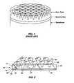
- FIG. 1shows a transducer aligned with a horn plate.
- a spacing gap between the emitter element and throats of the respective hornsis illustrated and identified as a key element in optimizing the efficiency of the horn array for ultrasonic energy.
- An additional objectis to provide an integrated emitter and acoustic transformer which is capable of high efficiency coupling between the emitter and surrounding air environment.
- a further object of this inventionis to provide a parametric sound system having improved performance, particularly within low frequency ranges.
- the emitter arrayincludes a plate support member having opposing first and second faces separated by an intermediate plate body.
- the plate bodyhas a plurality of conduits configured as an array of acoustic horns, with each horn having a small throat opening at the first face and an intermediate horn section which diverges to a broad mouth opening at the second face.
- An emitter membraneis positioned in direct contact with the first face and extends across the small throat openings. The emitter membrane is biased for (i) applying tension to the membrane extending across the throat openings and (ii) displacing the membrane into a non-planar configuration. This non-planar, stretched configuration permits application of a sonic frequency to the membrane for propagation through the intermediate horn section and out the broad mouth opening at the second face.
- emittersincluding an emitter having a PVDF (polyvinylidiene di-fluoride) membrane which operates in response to an applied voltage as an active driver element integrally coupled to the acoustic horn.
- Electrostatic and piezoelectric driverscan similarly be directly coupled to the acoustic horn.
- These devicesare representative of a general methodology for developing a high efficiency acoustic coupling device for coupling ultrasonic emitters to a surrounding air environment, based on the steps of a) integrally attaching an emitter membrane at a small throat opening of an acoustic horn; b) applying sonic frequencies to the emitter membrane to generate sonic compression waves at the small throat opening of the acoustic horn; and c) propagating the sonic compression wave through the acoustic horn for enhanced air coupling at a broad mouth of the horn.
- FIG. 1depicts a prior art example of an emitter configuration utilizing an array of horn transformers for acoustic coupling with air.
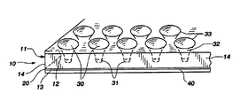
- FIG. 2shows an elevational view of an integral emitter/horn array constructed in accordance with the subject invention.
- FIG. 3is a cross-section view of a single horn.
- FIG. 4is a detailed sectional view of the integrated emitter and throat of the horn.
- FIGS. 5 through 8graphically illustrate alternative embodiments demonstrating various methods of displacing the emitter membrane within the small throat opening.
- FIG. 9graphically illustrates an application of the present invention as part of a parametric speaker system for generating audio frequencies from ultrasonic output.
- a sonic emitter array 10is illustrated in FIG. 2 . It comprises a plate support member 11 having opposing first and second faces 13 and 12 separated by an intermediate plate body 14 .
- the plate 11is preferably a rigid material (metal, ceramic, polymer, etc), and may be either conductive or nonconductive, depending on the method of driving an emitter membrane 20 directly coupled to the first face 13 .
- the thickness of the platewill vary, depending on the acoustic coupling properties required for specific frequency ranges and particular applications. Generally, the plate thickness will be within the range of 1 millimeter (mm) to 20 mm. The selection of acoustical, electrical and physical properties will be discussed hereafter.
- the plate bodyincludes a plurality of conduits configured as an array of acoustic horns 30 .
- Each hornhas a small throat opening 31 at the first face 13 and an intermediate horn section 32 which diverges to a broad mouth opening 33 at the second face 12 .
- the degree of flair in the intermediate horn section, as well as the size of the respective small throat and broad mouth openings 31 and 33may be configured in accordance with conventional design parameters. These parameters will be balanced and optimized, depending upon the degree of directionality desired, the bandwidth response selected and the gain and coupling efficiency intended. Detailed design considerations are therefore deemed unnecessary for enablement of the present disclosure.
- Representative dimensions illustrated in FIG. 2are a 10 mm diameter for the mouth 33 , 2 mm diameter for the throat opening, and 10 mm for length or thickness of the plate.
- the array of hornscomprise conduits which are molded to a desired shape within the plate support member for acoustic coupling of ultrasonic frequencies to surrounding air. Appropriate techniques are well known within the injection molding industry for implementing these procedures. Alternatively, the array of horns may have conduits which are machined to the desired shape.
- a preferred embodiment of the plate support membercomprises circular plate as opposed to the rectangular shape illustrated in FIG. 2 .
- Such a configurationoffers an emitted sound column of more uniform nature because of the common radius of the resulting beam output.
- Dimensions of the plate support membermay vary; however, the diameter is generally at least three inches.
- the configurationmay be planar or curved.
- a concave configurationenables selection of a curvature radius to minimize phase misalignment for a listener location at a predetermined distance from the emitter array. This is accomplished by adjusting the radius of curvature of the emitting face so that the distances from each mouth opening are common at a given listener location. Numerous other variations will be apparent to those of ordinary skill in the art.
- acoustic emittersmay be coupled directly to the opening 31 at the throat of the horn. Selection of a specific emitter will be a function of the intended use of the horn array. Generally these emitters fall within two classes.
- the first class of emitterscomprises those which function as the primary source of mechanical movement for development of compression waves.
- This classreferred to as acoustic drivers, includes an emitter membrane which is mechanically or physically displaced to create periodic compression waves in a direct or active mode.
- Examples of the first class of driversincludes piezoelectric emitters, mechanical oscillators, and similar structures which displace in response to energy supplied directly to the membrane.
- a preferred embodiment conceived as part of the present inventioninvolves the use a film or flexible membrane made of PVDF material. This material has demonstrated surprising utility with respect to direct generation of ultrasonic emissions as will be discussed hereafter. Because PVDF material responds directly to voltage variations, ultrasonic emissions can be directly generated at the small throat opening in a highly controlled manner.
- the second class of emittersis characterized by passive or indirect power transmission, rather than in an active or direct mode. Electrostatic and magnetostrictive emitters are representative of this group. Operation of these emitters requires an independent drive source such as a variable voltage back plate or some other driver which passively or indirectly displaces the emitter mounted at the throat opening 31 .
- an electrostatic membrane having a conductive filmmay be directly coupled at the small opening 31 , and pinched or otherwise biased into a state of tension.
- Ultrasonic electronic signalsare applied to a conductive back plate which is electrically insulated from the membrane film, thereby coupling the ultrasonic signal to the electrostatic membrane for generating the desired compression waves through the horn.
- Both classes of emittersare positioned in direct contact with the first face 13 and extend across the small throat openings. This is somewhat counter to teachings of the prior art, which have required a displacement gap between the emitter and the small opening of the horn.
- the present inventorshave discovered that by directly attaching the emitter at the first face 13 and in direct position at the throat of the horn develops a highly efficient ultrasonic emission source which couples surprisingly well with a surrounding air environment. Its operability as a parametric propagation source has been effectively demonstrated.
- a biasing meansis required for enabling the emitter membrane to properly function.
- This biasing meansmay be physically or inductively operative with respect to the emitter membrane, but must be capable of (i) applying tension to the membrane extending across the throat openings and (ii) displacing the membrane into a non-planar configuration. This is represented in FIG. 4 et.seq. by the slightly deformed or displaced emitter membrane 35 which is projecting within the small throat opening 31 .
- the emitter membraneis part of a continuous membrane 20 which is disposed across the first face 13 of the plate support member.
- the deformed emitter membrane 35may be a preformed dimple positioned within the continuous membrane 20 and in alignment with the opening.
- the dimpled structureforms part of the biasing means as described above, and would be complemented with a tension force to place the emitter membrane in biased position which permits vibrating motion consonant with a desired ultrasonic signal.
- a back plate 40is positioned behind the membrane and adjacent the small throat openings, and may also serve as part of the biasing means. For example, corresponding dimples 41 can be formed on the back plate in proper alignment to force the emitter membrane within the small throat openings 31 .
- a spacer element 43may be inserted between the back plate 40 and the emitter membrane 20 to displace the emitter portion 35 from contact with the back plate 40 . This may be enhanced by the capture of a pocket of air 45 as a cushion which provides displacement space for the emitter membrane 35 .
- vibration displacements activated by a variable voltage sourceare of such small distances that the gap formed by the pocket of air 45 may be very small.
- an outside pressure source Pmay be applied as illustrated in FIG.
- the emitter membraneis biased by positive pressure shown by arrows 47 .
- the air pocket 48is pressurized through a small conduit 49 which communicates with a plenum 50 or other pressurized source. This also permits uniform pressure on each member of the horn array, providing consistency in output between the respective emitter membranes 35 .
- the spacer element 43may also be viewed as structure for clamping the membrane in fixed position around the small throat opening such that vibrational energy is not transferred through the membrane to adjacent horns. This same function is performed by the back plate in the absence of the spacer element. Isolation of each emitter element 35 is important for minimizing cross transmission of vibrations through the continuous membrane 20 .
- the spacer and/or back platealso acts as a damping member to reduce vibrations carried through the plate support member 11 (FIG. 1 ).
- the isolated emitter sections 35can be tuned and electronically or mechanically activated to develop a uniform wave front with minimal distortion.
- the application of this emitter configuration with an array of horn-type acoustic transformersoffers significant advantages over other emitter systems.
- the back platemay also include protruding structure 41 aligned with each small throat opening as part of the biasing means.
- the protruding memberoperates to displace the emitter membrane slightly and/or to apply proper tension with sufficient displacement allow to activation as a sonic generator.
- the displacement distanceis so nominal that the protruding portion need not extend more than 3 mm.
- FIGS. 4 through 8illustrate various geometric shapes that are useful to displace the emitter membrane into the desired non-planar configuration.
- the protruding structure 41 shown in FIG. 4comprises a convex bump having a size approximately equal to the small throat opening such that the bump projects within the throat of the horn.
- This configurationis very effective in isolating and developing uniform vibration response across the emitter section.
- the back plateincludes means for developing a gap between the convex bump and the membrane to allow vibrational displacement of the membrane when activated with the sonic frequency, thereby avoiding distorting contact with the convex bump.
- Typical dimensions of the convex bumpinclude a radius of curvature of 10-30 mm and a height of 1-3 mm from the planar surface of the backplate.
- An additional method for developing the required gap between the convex bump and the membranecomprises structure for supplying an electrostatic charge operable to repel the membrane from the bump during operation. This can be accomplished by establishing a baseline signal within the PVDF material which maintains a threshold tension, enabling the desired output signal to be applied for the generation of the sonic output in the emitter. It is possible to utilize a carrier signal for this biasing purpose, with sidebands providing the output signal.
- a similar biasing meanscan be developed with structure for supplying a magnetic force operable in a manner similar to the electrostatic embodiment to repel the membrane from the bump during operation.
- a simple means for developing the required gap between the convex bump and the membranemay consist of a spacer ring positioned between the membrane and the back plate, with the bump being disposed in alignment with a central opening of the spacer ring.
- This spacer elementis representative of numerous forms of mechanical means useful for displacing the emitter membrane from the backplate and bump.
- the thickness of the spacerwill depend upon the range of frequency and amplitude of vibration of the emitter member.
- spacer elementswill vary in dimension from 1 to 3 mm. Numerous materials may be selected, balancing such factors as insulative properties, damping constants, expansion coefficients, and chemical/mechanical compatibility with the backplate and the support plate.
- FIGS. 6 to 8Other forms of mechanical means for developing the gap between the back plate and the membrane are represented in FIGS. 6 to 8 .
- Theseinclude a protruding structure having an apex configuration in contact with a central portion of the membrane to physically displace the membrane from the back plate.
- FIG. 6shows a conical structure 61 having an apex 62 in contact with a central portion of the membrane 63 to physically displace the membrane.
- FIG. 7comprises a pin structure 71 having an apex 72 in contact with a central portion of the membrane 73 .
- These embodimentsmay be provided with a spacer 43 to develop the desired gap between the back plate and membrane.
- the various shapesare to be considered as representative of the general concept that the emitter membrane can be mechanically displaced to provide the biasing and necessary gap for operation within the inventive concept.
- FIG. 8illustrates the placement of the projecting element directly from the back plate without presence of a spacer for gap formation. Instead, a small projection 81 extends at a sufficient length to displace the membrane 83 away from the back plate 40 to provide space for vibration. With minimal displacements such as occur with higher ultrasonic frequencies, small gaps 84 on each side of the projection 81 are sufficient to enable operation of the emitter.
- the present inventionoffers utility in many areas of sonic generation. It is particularly useful in coupling ultrasonic output to surrounding air. The efficiency of this system is most evident with respect to applications with parametric speaker systems where the signal source is coupled to an amplitude modulator for mixing audio frequencies with ultrasonic frequencies to develop an ultrasonic wave form with at least one sideband corresponding to the audio frequencies.
- the horn arraypropagates the combined carrier and sideband compression wave within the surrounding air environment which then decouples the audio frequencies to generate audio output as part of an acoustic heterodyne speaker system. Such a system is illustrated in FIG. 9 .
- This applicationutilizes a parametric or heterodyning technology, which is particularly adapted for the present thin film structure.
- the thin electrostatic film of the present inventionis well suited for operation at high ultrasonic frequencies in accordance with parametric speaker theory.
- a basic systemincludes an oscillator or digital ultrasonic wave source 104 for providing a base or carrier wave 108 .
- This wave 108is generally referred to as a first ultrasonic wave or primary wave.
- An amplitude modulating component 112is coupled to the output of the ultrasonic generator 104 and receives the base frequency 108 for mixing with a sonic or subsonic input signal 116 .
- the sonic or subsonic signal 116may be supplied in either analog or digital form, and could be music from any convention signal source 120 or other form of sound. If the input signal 116 includes upper and lower sidebands 117 , a filter component 124 may be included in the modulator to yield a single sideband output 118 on the modulated carrier frequency for selected bandwidths.
- the diaphragm 100is caused to emit the ultrasonic frequencies f 1 and f 2 as a new wave form 116 propagated at the face of the diaphragm 100 .
- This new wave forminteracts within the nonlinear medium of air 121 to generate the difference frequency 120 , as a new sonic or subsonic wave.
- the ability to have large quantities of emitter sectors formed in an emitter horn arrayis particularly well suited for generation of a uniform wave front which can propagate quality audio output at meaningful volumes.
- the present inventionis able to function as described because the ultrasonic signals corresponding to f 1 and f 2 interfere in air according to the principles of acoustical heterodyning.
- Acoustical heterodyningis somewhat of a mechanical counterpart to the electrical heterodyning effect which takes place in a non-linear circuit.
- amplitude modulation in an electrical circuitis a heterodyning process.
- the heterodyne processitself is simply the creation of two new waves. The new waves are the sum and the difference of two fundamental waves.
- the new waves equaling the sum and difference of the fundamental wavesare observed to occur when at least two ultrasonic compression waves interact or interfere in air.
- the preferred transmission medium of the present inventionis air because it is a highly compressible medium that responds non-linearly under different conditions. This non-linearity of air enables the heterodyning process to take place, decoupling the difference signal from the ultrasonic output.
- any compressible fluidcan function as the transmission medium if desired.
- the present inventionmay be viewed from the following method steps comprising: a) integrally attaching an emitter membrane at a small throat opening of an acoustic horn; b) applying sonic frequencies to the emitter membrane to generate sonic compression waves at the small throat opening of the acoustic horn; and c) propagating the sonic compression wave through the acoustic horn for enhanced air coupling at a broad mouth of the horn.
- the platemay be formed by preparing a plate support member having opposing first and second faces separated by an intermediate plate body.
- the plate bodyincludes a plurality of conduits configured as an array of acoustic horns, each horn having a small throat opening at the first face and an intermediate horn section which diverges to a broad mouth opening at the second face.
- the emitter membraneis positioned in direct contact with the first face and extends across the small throat openings.
- Biasing meansis provided to the emitter membrane for (i) applying tension to the membrane extending across the throat openings and (ii) displacing the membrane into a non-planar configuration.
- a sonic frequencyis imposed on the membrane for propagation through the intermediate horn section and out the broad mouth opening at the second face.
- the present disclosureis merely representative of the basic inventive concepts set forth in the following claims.
- other variationswill be recognized, such as biasing the emitter membrane by coupling a back plate directly against the emitter membrane to pinch the membrane at the small throat opening and isolate the membrane from adjacent acoustic horns within the plate support member.
- the emitter membranemay perform the additional step of actively driving the generation of compression waves within the acoustic horn, as opposed to passive or inductive methods generally described in this disclosure.
Landscapes
- Physics & Mathematics (AREA)
- Engineering & Computer Science (AREA)
- Acoustics & Sound (AREA)
- Multimedia (AREA)
- Transducers For Ultrasonic Waves (AREA)
- Circuit For Audible Band Transducer (AREA)
Abstract
Description
Claims (36)
Priority Applications (1)
| Application Number | Priority Date | Filing Date | Title |
|---|---|---|---|
| US09/819,301US6925187B2 (en) | 2000-03-28 | 2001-03-27 | Horn array emitter |
Applications Claiming Priority (2)
| Application Number | Priority Date | Filing Date | Title |
|---|---|---|---|
| US19277800P | 2000-03-28 | 2000-03-28 | |
| US09/819,301US6925187B2 (en) | 2000-03-28 | 2001-03-27 | Horn array emitter |
Related Child Applications (1)
| Application Number | Title | Priority Date | Filing Date |
|---|---|---|---|
| US11/196,803Continuation-In-PartUS20060233404A1 (en) | 2000-03-28 | 2005-08-02 | Horn array emitter |
Publications (2)
| Publication Number | Publication Date |
|---|---|
| US20010033124A1 US20010033124A1 (en) | 2001-10-25 |
| US6925187B2true US6925187B2 (en) | 2005-08-02 |
Family
ID=26888355
Family Applications (1)
| Application Number | Title | Priority Date | Filing Date |
|---|---|---|---|
| US09/819,301Expired - Fee RelatedUS6925187B2 (en) | 2000-03-28 | 2001-03-27 | Horn array emitter |
Country Status (1)
| Country | Link |
|---|---|
| US (1) | US6925187B2 (en) |
Cited By (12)
| Publication number | Priority date | Publication date | Assignee | Title |
|---|---|---|---|---|
| US20060233404A1 (en)* | 2000-03-28 | 2006-10-19 | American Technology Corporation. | Horn array emitter |
| US7376236B1 (en)* | 1997-03-17 | 2008-05-20 | American Technology Corporation | Piezoelectric film sonic emitter |
| US20090308487A1 (en)* | 2006-04-19 | 2009-12-17 | Anthony Collings | Ultrasonic Transducer Systems |
| US20110165720A1 (en)* | 2005-08-23 | 2011-07-07 | Analog Devices, Inc. | Microphone with Irregular Diaphragm |
| US8309045B2 (en) | 2011-02-11 | 2012-11-13 | General Electric Company | System and method for controlling emissions in a combustion system |
| US20130044904A1 (en)* | 2011-08-16 | 2013-02-21 | Empire Technology Development Llc | Techniques for generating audio signals |
| US8452038B2 (en) | 2010-04-29 | 2013-05-28 | Avago Technologies General Ip (Singapore) Pte. Ltd. | Multi-throat acoustic horn for acoustic filtering |
| US8983098B2 (en)* | 2012-08-14 | 2015-03-17 | Turtle Beach Corporation | Substantially planate parametric emitter and associated methods |
| US9913048B2 (en) | 2014-02-08 | 2018-03-06 | Empire Technology Development Llc | MEMS-based audio speaker system with modulation element |
| US10123126B2 (en) | 2014-02-08 | 2018-11-06 | Empire Technology Development Llc | MEMS-based audio speaker system using single sideband modulation |
| US10271146B2 (en) | 2014-02-08 | 2019-04-23 | Empire Technology Development Llc | MEMS dual comb drive |
| US10284961B2 (en) | 2014-02-08 | 2019-05-07 | Empire Technology Development Llc | MEMS-based structure for pico speaker |
Families Citing this family (29)
| Publication number | Priority date | Publication date | Assignee | Title |
|---|---|---|---|---|
| WO2005017965A2 (en)* | 2003-08-06 | 2005-02-24 | Measurement Specialities, Inc. | Ultrasonic air transducer arrays using polymer piezoelectric films and impedance matching structures for ultrasonic polymer transducer arrays |
| JP4264388B2 (en)* | 2004-07-01 | 2009-05-13 | 富士通株式会社 | Semiconductor chip bonding method and bonding apparatus |
| GB2443228B (en)* | 2006-10-25 | 2010-02-10 | Gary Paul Nicholson | Piezo-electric loudspeaker |
| SG148061A1 (en)* | 2007-05-25 | 2008-12-31 | Sony Corp | An ultrasonic transducer array and a method for making a transducer array |
| GB2513884B (en) | 2013-05-08 | 2015-06-17 | Univ Bristol | Method and apparatus for producing an acoustic field |
| GB2530036A (en) | 2014-09-09 | 2016-03-16 | Ultrahaptics Ltd | Method and apparatus for modulating haptic feedback |
| CA2976312C (en) | 2015-02-20 | 2023-06-13 | Ultrahaptics Ip Limited | Perceptions in a haptic system |
| CN107534810B (en) | 2015-02-20 | 2019-12-20 | 超级触觉资讯处理有限公司 | Method for providing improved haptic feedback |
| US10818162B2 (en) | 2015-07-16 | 2020-10-27 | Ultrahaptics Ip Ltd | Calibration techniques in haptic systems |
| WO2017053716A1 (en)* | 2015-09-24 | 2017-03-30 | Frank Joseph Pompei | Ultrasonic transducers |
| US11189140B2 (en) | 2016-01-05 | 2021-11-30 | Ultrahaptics Ip Ltd | Calibration and detection techniques in haptic systems |
| US10268275B2 (en) | 2016-08-03 | 2019-04-23 | Ultrahaptics Ip Ltd | Three-dimensional perceptions in haptic systems |
| US10943578B2 (en) | 2016-12-13 | 2021-03-09 | Ultrahaptics Ip Ltd | Driving techniques for phased-array systems |
| US11531395B2 (en) | 2017-11-26 | 2022-12-20 | Ultrahaptics Ip Ltd | Haptic effects from focused acoustic fields |
| EP3729417B1 (en) | 2017-12-22 | 2025-09-10 | Ultrahaptics Ip Ltd | Tracking in haptic systems |
| EP3729418B1 (en) | 2017-12-22 | 2024-11-20 | Ultrahaptics Ip Ltd | Minimizing unwanted responses in haptic systems |
| CA3098642C (en) | 2018-05-02 | 2022-04-19 | Ultrahaptics Ip Ltd | Blocking plate structure for improved acoustic transmission efficiency |
| US11098951B2 (en) | 2018-09-09 | 2021-08-24 | Ultrahaptics Ip Ltd | Ultrasonic-assisted liquid manipulation |
| US11378997B2 (en) | 2018-10-12 | 2022-07-05 | Ultrahaptics Ip Ltd | Variable phase and frequency pulse-width modulation technique |
| EP3906462B1 (en) | 2019-01-04 | 2025-06-18 | Ultrahaptics IP Ltd | Mid-air haptic textures |
| US12373033B2 (en) | 2019-01-04 | 2025-07-29 | Ultrahaptics Ip Ltd | Mid-air haptic textures |
| US11842517B2 (en) | 2019-04-12 | 2023-12-12 | Ultrahaptics Ip Ltd | Using iterative 3D-model fitting for domain adaptation of a hand-pose-estimation neural network |
| US11374586B2 (en) | 2019-10-13 | 2022-06-28 | Ultraleap Limited | Reducing harmonic distortion by dithering |
| US11553295B2 (en) | 2019-10-13 | 2023-01-10 | Ultraleap Limited | Dynamic capping with virtual microphones |
| US11169610B2 (en) | 2019-11-08 | 2021-11-09 | Ultraleap Limited | Tracking techniques in haptic systems |
| US11715453B2 (en) | 2019-12-25 | 2023-08-01 | Ultraleap Limited | Acoustic transducer structures |
| US11816267B2 (en) | 2020-06-23 | 2023-11-14 | Ultraleap Limited | Features of airborne ultrasonic fields |
| US11886639B2 (en) | 2020-09-17 | 2024-01-30 | Ultraleap Limited | Ultrahapticons |
| US12232857B2 (en)* | 2021-09-08 | 2025-02-25 | Shanghai United Imaging Healthcare Co., Ltd. | Devices, systems, and methods for noise reduction |
Citations (7)
| Publication number | Priority date | Publication date | Assignee | Title |
|---|---|---|---|---|
| US3136867A (en) | 1961-09-25 | 1964-06-09 | Ampex | Electrostatic transducer |
| US3908098A (en)* | 1972-08-04 | 1975-09-23 | Sony Corp | Electrostatic transducer |
| US4297538A (en)* | 1979-07-23 | 1981-10-27 | The Stoneleigh Trust | Resonant electroacoustic transducer with increased band width response |
| US4322877A (en) | 1978-09-20 | 1982-04-06 | Minnesota Mining And Manufacturing Company | Method of making piezoelectric polymeric acoustic transducer |
| US5142511A (en) | 1989-03-27 | 1992-08-25 | Mitsubishi Mining & Cement Co., Ltd. | Piezoelectric transducer |
| US5590212A (en) | 1993-07-30 | 1996-12-31 | Sony Corporation | Diaphragm for a capacitance type loudspeaker |
| US6744899B1 (en)* | 1996-05-28 | 2004-06-01 | Robert M. Grunberg | Direct coupling of waveguide to compression driver having matching slot shaped throats |
- 2001
- 2001-03-27USUS09/819,301patent/US6925187B2/ennot_activeExpired - Fee Related
Patent Citations (7)
| Publication number | Priority date | Publication date | Assignee | Title |
|---|---|---|---|---|
| US3136867A (en) | 1961-09-25 | 1964-06-09 | Ampex | Electrostatic transducer |
| US3908098A (en)* | 1972-08-04 | 1975-09-23 | Sony Corp | Electrostatic transducer |
| US4322877A (en) | 1978-09-20 | 1982-04-06 | Minnesota Mining And Manufacturing Company | Method of making piezoelectric polymeric acoustic transducer |
| US4297538A (en)* | 1979-07-23 | 1981-10-27 | The Stoneleigh Trust | Resonant electroacoustic transducer with increased band width response |
| US5142511A (en) | 1989-03-27 | 1992-08-25 | Mitsubishi Mining & Cement Co., Ltd. | Piezoelectric transducer |
| US5590212A (en) | 1993-07-30 | 1996-12-31 | Sony Corporation | Diaphragm for a capacitance type loudspeaker |
| US6744899B1 (en)* | 1996-05-28 | 2004-06-01 | Robert M. Grunberg | Direct coupling of waveguide to compression driver having matching slot shaped throats |
Non-Patent Citations (1)
| Title |
|---|
| Multi-Horn Matching Plate for Ultrasonic Transducers by Neville H. Fletcher and Suszanne Thwaites, Research School of Physical Sciences and Engineering, Australian National University, Canberra ACT 2601, Australia. |
Cited By (19)
| Publication number | Priority date | Publication date | Assignee | Title |
|---|---|---|---|---|
| US7376236B1 (en)* | 1997-03-17 | 2008-05-20 | American Technology Corporation | Piezoelectric film sonic emitter |
| US20060233404A1 (en)* | 2000-03-28 | 2006-10-19 | American Technology Corporation. | Horn array emitter |
| US20110165720A1 (en)* | 2005-08-23 | 2011-07-07 | Analog Devices, Inc. | Microphone with Irregular Diaphragm |
| US8358793B2 (en)* | 2005-08-23 | 2013-01-22 | Analog Devices, Inc. | Microphone with irregular diaphragm |
| US20090308487A1 (en)* | 2006-04-19 | 2009-12-17 | Anthony Collings | Ultrasonic Transducer Systems |
| US8763927B2 (en)* | 2006-04-19 | 2014-07-01 | Commonwealth Scientific And Industrial Research Organisation | Ultrasonic transducer systems |
| US8452038B2 (en) | 2010-04-29 | 2013-05-28 | Avago Technologies General Ip (Singapore) Pte. Ltd. | Multi-throat acoustic horn for acoustic filtering |
| US8309045B2 (en) | 2011-02-11 | 2012-11-13 | General Electric Company | System and method for controlling emissions in a combustion system |
| US20130044904A1 (en)* | 2011-08-16 | 2013-02-21 | Empire Technology Development Llc | Techniques for generating audio signals |
| US8861752B2 (en)* | 2011-08-16 | 2014-10-14 | Empire Technology Development Llc | Techniques for generating audio signals |
| AU2011374985B2 (en)* | 2011-08-16 | 2015-06-11 | Empire Technology Development Llc | Techniques for generating audio signals |
| AU2011374985C1 (en)* | 2011-08-16 | 2015-11-12 | Empire Technology Development Llc | Techniques for generating audio signals |
| US9866948B2 (en) | 2011-08-16 | 2018-01-09 | Empire Technology Development Llc | Techniques for generating audio signals |
| US10448146B2 (en) | 2011-08-16 | 2019-10-15 | Empire Technology Development Llc | Techniques for generating audio signals |
| US8983098B2 (en)* | 2012-08-14 | 2015-03-17 | Turtle Beach Corporation | Substantially planate parametric emitter and associated methods |
| US9913048B2 (en) | 2014-02-08 | 2018-03-06 | Empire Technology Development Llc | MEMS-based audio speaker system with modulation element |
| US10123126B2 (en) | 2014-02-08 | 2018-11-06 | Empire Technology Development Llc | MEMS-based audio speaker system using single sideband modulation |
| US10271146B2 (en) | 2014-02-08 | 2019-04-23 | Empire Technology Development Llc | MEMS dual comb drive |
| US10284961B2 (en) | 2014-02-08 | 2019-05-07 | Empire Technology Development Llc | MEMS-based structure for pico speaker |
Also Published As
| Publication number | Publication date |
|---|---|
| US20010033124A1 (en) | 2001-10-25 |
Similar Documents
| Publication | Publication Date | Title |
|---|---|---|
| US6925187B2 (en) | Horn array emitter | |
| JP4802998B2 (en) | Electrostatic ultrasonic transducer drive control method, electrostatic ultrasonic transducer, ultrasonic speaker using the same, audio signal reproduction method, superdirective acoustic system, and display device | |
| JP5103873B2 (en) | Electrostatic ultrasonic transducer drive control method, electrostatic ultrasonic transducer, ultrasonic speaker using the same, audio signal reproduction method, superdirective acoustic system, and display device | |
| US6606389B1 (en) | Piezoelectric film sonic emitter | |
| US8199931B1 (en) | Parametric loudspeaker with improved phase characteristics | |
| US7668323B2 (en) | Electrostatic ultrasonic transducer and ultrasonic speaker | |
| US6151398A (en) | Magnetic film ultrasonic emitter | |
| JPH11164384A (en) | Super directional speaker and speaker drive method | |
| JP4285537B2 (en) | Electrostatic ultrasonic transducer | |
| JP2002526004A (en) | Parametric speaker with electro-acoustic diaphragm transducer | |
| US20050244016A1 (en) | Parametric loudspeaker with electro-acoustical diaphragm transducer | |
| JP2007503742A (en) | Parametric transducer with emitter film | |
| JP2008244964A (en) | Electrostatic ultrasonic transducer, electrostatic transducer, ultrasonic speaker, speaker device, audio signal reproduction method using electrostatic ultrasonic transducer, directional acoustic system, and display device | |
| JP2001339791A (en) | Piezoelectric acoustic device | |
| JP2003520002A (en) | Piezo film acoustic emitter | |
| US20060233404A1 (en) | Horn array emitter | |
| CN1750716B (en) | Supersonic speaker, acoustic system and method for control of supersonic transducer | |
| JP2009118093A (en) | Electrostatic transducer and ultrasonic speaker | |
| JP2008118247A (en) | Electrostatic ultrasonic transducer, ultrasonic speaker using the same, audio signal reproduction method, superdirective acoustic system, and display device | |
| JP2009118094A (en) | Electrostatic transducer and ultrasonic speaker | |
| WO2008050123A1 (en) | Loudspeakers | |
| KR200168498Y1 (en) | Thin Film Ultrasonic Transducer | |
| JP4803246B2 (en) | Ultrasonic speaker, audio signal reproduction method, superdirective acoustic system | |
| JP2005039437A (en) | Ultrasonic speaker and signal reproduction method of ultrasonic speaker | |
| JP4016697B2 (en) | Speaker device |
Legal Events
| Date | Code | Title | Description |
|---|---|---|---|
| AS | Assignment | Owner name:AMERICAN TECHNOLOGY CORPORATION, CALIFORNIA Free format text:ASSIGNMENT OF ASSIGNORS INTEREST;ASSIGNORS:NORRIS, ELWOOD G.;CROFT, III, JAMES J.;REEL/FRAME:016176/0201;SIGNING DATES FROM 20050527 TO 20050617 | |
| FPAY | Fee payment | Year of fee payment:4 | |
| AS | Assignment | Owner name:PARAMETRIC SOUND CORPORATION, NEVADA Free format text:ASSIGNMENT OF ASSIGNORS INTEREST;ASSIGNOR:LRAD CORPORATION;REEL/FRAME:025466/0748 Effective date:20101013 Owner name:LRAD CORPORATION, CALIFORNIA Free format text:CHANGE OF NAME;ASSIGNOR:AMERICAN TECHNOLOGY CORPORATION;REEL/FRAME:025466/0409 Effective date:20100324 | |
| FPAY | Fee payment | Year of fee payment:8 | |
| AS | Assignment | Owner name:PNC BANK, NATIONAL ASSOCIATION, PENNSYLVANIA Free format text:SECURITY INTEREST IN U.S. PATENTS AND TRADEMARKS;ASSIGNOR:PARAMETRIC SOUND CORPORATION;REEL/FRAME:032032/0328 Effective date:20140115 | |
| AS | Assignment | Owner name:PARAMETRIC SOUND CORPORATION, NEW YORK Free format text:TERMINATION AND RELEASE OF IP SECURITY AGREEMENT;ASSIGNOR:PNC BANK, NATIONAL ASSOCIATION, AS AGENT;REEL/FRAME:032608/0156 Effective date:20140331 Owner name:BANK OF AMERICA, N.A., AS AGENT, CALIFORNIA Free format text:MEMORANDUM AND NOTICE OF SECURITY INTEREST IN INTELLECTUAL PROPERTY;ASSIGNOR:PARAMETRIC SOUND CORPORATION;REEL/FRAME:032608/0143 Effective date:20140331 | |
| AS | Assignment | Owner name:TURTLE BEACH CORPORATION, CALIFORNIA Free format text:CHANGE OF NAME;ASSIGNOR:PARAMETRIC SOUND CORPORATION;REEL/FRAME:033917/0789 Effective date:20140520 | |
| AS | Assignment | Owner name:CRYSTAL FINANCIAL LLC, AS AGENT, MASSACHUSETTS Free format text:SECURITY INTEREST;ASSIGNOR:TURTLE BEACH CORPORATION;REEL/FRAME:036159/0952 Effective date:20150722 | |
| AS | Assignment | Owner name:BANK OF AMERICA, N.A., AS AGENT, CALIFORNIA Free format text:SECURITY INTEREST;ASSIGNORS:TURTLE BEACH CORPORATION;VOYETRA TURTLE BEACH, INC.;REEL/FRAME:036189/0326 Effective date:20150722 | |
| REMI | Maintenance fee reminder mailed | ||
| LAPS | Lapse for failure to pay maintenance fees | Free format text:PATENT EXPIRED FOR FAILURE TO PAY MAINTENANCE FEES (ORIGINAL EVENT CODE: EXP.) | |
| STCH | Information on status: patent discontinuation | Free format text:PATENT EXPIRED DUE TO NONPAYMENT OF MAINTENANCE FEES UNDER 37 CFR 1.362 | |
| FP | Expired due to failure to pay maintenance fee | Effective date:20170802 | |
| AS | Assignment | Owner name:CRYSTAL FINANCIAL LLC, AS AGENT, MASSACHUSETTS Free format text:SECURITY INTEREST;ASSIGNOR:TURTLE BEACH CORPORATION;REEL/FRAME:045573/0722 Effective date:20180305 | |
| AS | Assignment | Owner name:BANK OF AMERICA, N.A., AS AGENT, CALIFORNIA Free format text:SECURITY INTEREST;ASSIGNORS:TURTLE BEACH CORPORATION;VOYETRA TURTLE BEACH, INC.;REEL/FRAME:045776/0648 Effective date:20180305 | |
| AS | Assignment | Owner name:TURTLE BEACH CORPORATION, CALIFORNIA Free format text:TERMINATION AND RELEASE OF INTELLECTUAL PROPERTY SECURITY AGREEMENTS;ASSIGNOR:CRYSTAL FINANCIAL LLC;REEL/FRAME:048965/0001 Effective date:20181217 Owner name:TURTLE BEACH CORPORATION, CALIFORNIA Free format text:TERMINATION AND RELEASE OF INTELLECTUAL PROPERTY SECURITY AGREEMENTS;ASSIGNOR:CRYSTAL FINANCIAL LLC;REEL/FRAME:047954/0007 Effective date:20181217 |