US6924791B1 - Method and apparatus for automatic power-up and power-down of a computer system based on the positions of an associated stylus and/or hinge - Google Patents
Method and apparatus for automatic power-up and power-down of a computer system based on the positions of an associated stylus and/or hingeDownload PDFInfo
- Publication number
- US6924791B1 US6924791B1US09/522,274US52227400AUS6924791B1US 6924791 B1US6924791 B1US 6924791B1US 52227400 AUS52227400 AUS 52227400AUS 6924791 B1US6924791 B1US 6924791B1
- Authority
- US
- United States
- Prior art keywords
- computer system
- power
- digitizer
- stylus
- display screen
- Prior art date
- Legal status (The legal status is an assumption and is not a legal conclusion. Google has not performed a legal analysis and makes no representation as to the accuracy of the status listed.)
- Expired - Fee Related
Links
Images


Classifications
- G—PHYSICS
- G06—COMPUTING OR CALCULATING; COUNTING
- G06F—ELECTRIC DIGITAL DATA PROCESSING
- G06F1/00—Details not covered by groups G06F3/00 - G06F13/00 and G06F21/00
- G06F1/26—Power supply means, e.g. regulation thereof
- G06F1/32—Means for saving power
- G06F1/3203—Power management, i.e. event-based initiation of a power-saving mode
- G—PHYSICS
- G06—COMPUTING OR CALCULATING; COUNTING
- G06F—ELECTRIC DIGITAL DATA PROCESSING
- G06F1/00—Details not covered by groups G06F3/00 - G06F13/00 and G06F21/00
- G06F1/16—Constructional details or arrangements
- G06F1/1613—Constructional details or arrangements for portable computers
- G06F1/1626—Constructional details or arrangements for portable computers with a single-body enclosure integrating a flat display, e.g. Personal Digital Assistants [PDAs]
- G—PHYSICS
- G06—COMPUTING OR CALCULATING; COUNTING
- G06F—ELECTRIC DIGITAL DATA PROCESSING
- G06F1/00—Details not covered by groups G06F3/00 - G06F13/00 and G06F21/00
- G06F1/16—Constructional details or arrangements
- G06F1/1613—Constructional details or arrangements for portable computers
- G06F1/1632—External expansion units, e.g. docking stations
- G—PHYSICS
- G06—COMPUTING OR CALCULATING; COUNTING
- G06F—ELECTRIC DIGITAL DATA PROCESSING
- G06F1/00—Details not covered by groups G06F3/00 - G06F13/00 and G06F21/00
- G06F1/26—Power supply means, e.g. regulation thereof
- G—PHYSICS
- G06—COMPUTING OR CALCULATING; COUNTING
- G06F—ELECTRIC DIGITAL DATA PROCESSING
- G06F2200/00—Indexing scheme relating to G06F1/04 - G06F1/32
- G06F2200/16—Indexing scheme relating to G06F1/16 - G06F1/18
- G06F2200/163—Indexing scheme relating to constructional details of the computer
- G06F2200/1632—Pen holder integrated in the computer
- G—PHYSICS
- G06—COMPUTING OR CALCULATING; COUNTING
- G06F—ELECTRIC DIGITAL DATA PROCESSING
- G06F2200/00—Indexing scheme relating to G06F1/04 - G06F1/32
- G06F2200/16—Indexing scheme relating to G06F1/16 - G06F1/18
- G06F2200/163—Indexing scheme relating to constructional details of the computer
- G06F2200/1634—Integrated protective display lid, e.g. for touch-sensitive display in handheld computer
Definitions
- the present inventionrelates to the field of computer systems that utilize a digitizer and stylus. More specifically, the present invention relates to power-on and power-off mechanisms for portable computer systems that utilize a digitizer and an associated stylus or that have a cover.
- Palmtop computer systemis a computer that is small enough to be held in the hand of a user and can therefore be “palm-sized.” Most palmtop computer systems are used to implement various Personal Information Management (PIM) applications such as an address book, a daily organizer and electronic notepads, to name a few. Palmtop computers with PIM software have been know as Personal Digital Assistants (PDAs).
- PIMPersonal Information Management
- Palmtop computers using keyboardshave keyboard devices that are so small that a user cannot touch-type.
- a usermust either place the palmtop computer system down onto a flat surface, so the user can type with both hands, or the user holds the palmtop computer system with two hands and types with thumbs only.
- some palmtop computersutilize a touch screen and display an image of a small keyboard thereon.
- a small keyboard imageis displayed on the display screen.
- the userthen interacts with the on-screen small keyboard image to enter characters, usually one character at a time.
- the displayed keyboard imagee.g., “virtual keyboard”
- the usertaps the screen location of a character with a pen or stylus. That corresponding character is then recognized and added to a data entry field, also displayed on the screen.
- the virtual keyboard input systemcan be a tedious input process.
- palmtop computersInstead of using a mechanical keyboard device or a displayed keyboard, many palmtop computers employ a pen and a digitizer pad as an input system.
- the pen and digitizer pad combinationworks well for palmtop computers because the arrangement allows a user to hold the palmtop computer system in one hand while writing with the pen onto the digitizer pad with the other hand.
- Digitizershave eliminated the need for a mechanical keyboard device. Therefore, palmtop computer systems are readily portable and can easily be carried on or near the user, e.g., in a pocket, purse or briefcase. Since they can be carried by a user, the user has many opportunities to use the palmtop computer during the day. Since the palmtop computer is typically battery operated, it is recommended to turn off the computer at the completion of each separate use. As such, each time the palmtop is used, an on/off button is typically pressed to turn on power to the computer system, including the display device. Therefore, each time the palmtop computer is to be used, the on/off button is pressed and after use the on/off button is pressed again to turn off the palmtop computer.
- the computer systemis a portable computer having a logic board, a display screen, a digitizer and a receiving slot for an associated stylus.
- the stylusis used with the digitizer in well known character recognition modes.
- a switchautomatically turns full power onto the computer system thereby allowing a user full use of the computer without requiring an on/off button to be pressed.
- the switchautomatically returns the computer to a power reduction mode where one or all of the components of the computer are powered down.
- the switchcan be made of a single detector or a dual detector combination and can be of a mechanical, electromagnetic, optical, inductive, capacitive or electrical nature.
- the switch and detectorcan also be implemented using a microswitch device.
- the stylus-based automatic power-up and power-down featureswork in concert with other power-up and power-down mechanisms of the computer, such power-on interrupts, the on/off button, and time-out power off modes.
- the stylusis a hinge attached to a cover that can be rotated to protect the palmtop computer (like a book cover) or rotated away to use the palmtop computer (like opening a book).
- the switchWhen rotated to cover, the switch automatically powers down the computer.
- the switchWhen rotated out for computer use, the switch automatically powers up the computer.
- an embodiment of the present inventionincludes a computer system comprising: a processor coupled to bus; a memory unit coupled to the bus; a display screen coupled to the bus; a digitizer coupled to the bus; a case for supporting the processor, the memory unit, the display screen and the digitizer, the case having a slot located therein for receiving a stylus; a detector for detecting a stylus within said slot; and a switch coupled to the detector and for generating a signal to power up the processor, the display screen and the digitizer when the stylus is removed from the slot and wherein the switch is also for generating a signal to place the processor, the display screen and the digitizer into a power conservation mode when the stylus is inserted into the slot.
- Embodimentsinclude a power on and power off method implemented in accordance with the above.
- Embodimentsalso include a computer system comprising: a processor coupled to bus; a memory unit coupled to the bus; a display screen coupled to the bus; a digitizer coupled to the bus; a case for supporting the processor, the memory unit, the display screen and the digitizer, the case having a slot located therein for receiving a hinge attached to a protective cover; a detector for detecting the rotational positions of the hinge within the slot; a switch coupled to said detector and for generating a signal to automatically power up the processor, the display screen and the digitizer when the hinge is rotated such that the cover is not laid over the display screen and wherein the switch is also for generating a signal to automatically place the processor, the display screen and the digitizer into a power conservation mode when the hinge is rotated such that the cover is laid over the display screen.
- FIG. 1is system illustration of a palmtop or “palm sized” computer system connected to other computer systems and the Internet via a cradle device.
- FIG. 2Ais a top side perspective view of a palmtop computer system that can be used as a platform for the automatic power-up and power-down embodiments of the present invention.
- FIG. 2Bis a bottom side perspective view of the palmtop computer system of FIG. 2 A.
- FIG. 3is an exploded view of the components of the palmtop computer system of FIG. 2 A.
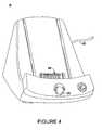
- FIG. 4is a perspective view of the cradle device for connecting the palmtop computer system to other systems via a communication interface.
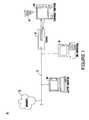
- FIG. 5is a logical block diagram of the palmtop computer system in accordance with an embodiment of the present invention.
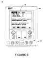
- FIG. 6is a front view of a palm top computer system illustrating the display screen, digitizer regions and an exemplary menu of a text display application.
- FIG. 7is a cross section of a stylus receiving slot incorporated within the casing of the portable computer system of an embodiment of the present invention and having a single proximity detector element.
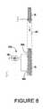
- FIG. 8is a cross section of a stylus receiving slot incorporated within the casing of the portable computer system of an embodiment of the present invention and having a pair of proximity detector elements.
- FIG. 9 A and FIG. 9Bare steps performed by an embodiment of the present invention for automatically powering-up and automatically powering-down a computer system based on the position of a stylus.
- FIG. 10illustrates a three dimensional view of a stylus receiving slot and a stylus for use in the hinge embodiment of the present invention.
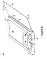
- FIG. 11illustrates a perspective view of the portable computer system with the hinge embodiment of the present invention.
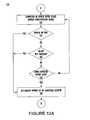
- FIG. 12 A and FIG. 12Bare steps performed by an embodiment of the present invention for automatically powering-up and automatically powering-down a computer system based on the rotation of a hinge.
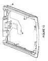
- FIG. 13illustrates a casing used in one embodiment of the present invention having a slot (or rail) for receiving a stylus or a cover hinge.
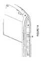
- FIG. 14illustrates the slot (or rail) for receiving a stylus or a cover hinge and also illustrates a detector element in the slot.
- FIG. 1illustrates a system 50 that can be used in conjunction with the automatic power on and power off features of the present invention.
- System 50comprises a host computer system 56 which can either be a desktop unit as shown, or, alternatively, can be a laptop system 58 .
- one or more host computer systemscan be used within system 50 .
- Host computer systems 58 and 56are shown connected to a communication bus 54 , which in one embodiment can be a serial communication bus, but could be of any of a number of well known designs, e.g., a parallel bus, Ethernet Local Area Network (LAN), etc.
- bus 54can provide communication with the Internet 52 using a number of well known protocols.
- bus 54is also coupled to a cradle 60 for receiving and initiating communication with a palm top (“palm-sized”) portable computer system 100 of the present invention.
- Cradle 60provides an electrical and mechanical communication interface between bus 54 (and anything coupled to bus 54 ) and the computer system 100 for two way communications.
- Computer system 100also contains a wireless infrared communication mechanism 64 for sending and receiving information from other devices.
- FIG. 2Ais a perspective illustration of the top face 100 a of one embodiment of the palmtop computer system of the present invention.
- the top face 110 acontains a display screen 105 surrounded by a bezel or cover.
- Aremovable stylus 80is also shown.
- the display screen 105is a touch screen able to register contact between the screen and the tip of the stylus 80 .
- the stylus 80can be of any material to make contact with the screen 105 .
- the stylus 80is inserted into a receiving slot or rail 350 . Slot or rail 350 acts to hold the stylus when the computer system 100 a is not in use.
- slot or rail 350also contains switching devices for automatically powering down and automatically power up computer system 100 a based on the position of the stylus 80 .
- the top face 100 aalso contains one or more dedicated and/or programmable buttons 75 for selecting information and causing the computer system to implement functions.
- the on/off button 95is also shown.
- FIG. 2Aalso illustrates a handwriting recognition pad or “digitizer” containing two regions 106 a and 106 b .
- Region 106 ais for the drawing of alpha characters therein for automatic recognition (and generally not used for recognizing numeric characters) and region 106 b is for the drawing of numeric characters therein for automatic recognition (and generally not used for recognizing numeric characters).
- the stylus 80is used for stroking a character within one of the regions 106 a and 106 b .
- the stroke informationis then fed to an internal processor for automatic character recognition. Once characters are recognized, they are typically displayed on the screen 105 for verification and/or modification.
- the digitizer 160records both the (x, y) coordinate value of the current location of the stylus and also simultaneously records the pressure that the stylus exerts on the face of the digitizer pad.
- the coordinate values (spatial information) and pressure dataare then output on separate channels for sampling by the processor 101 (FIG. 5 ).
- the processor 101FIG. 5
- FIG. 2Billustrates the bottom side 100 b of one embodiment of the palmtop computer system of the present invention.
- An optional extendible antenna 85is shown and also a battery storage compartment door 90 is shown.
- a communication interface 108is also shown.
- the serial communication interface 108is a serial communication port, but could also alternatively be of any of a number of well known communication standards and protocols, e.g., parallel, SCSI, Firewire (IEEE 1394), Ethernet, etc.
- FIG. 2Bis also shown the stylus receiving slot or rail 350 .
- FIG. 3is an exploded view of the palmtop computer system 100 in accordance with one implementation.
- System 100contains a front cover 210 having an outline of region 106 and holes 75 a for receiving buttons 75 b .
- a flat panel display 105(both liquid crystal display and touch screen) fits into front cover 210 . Any of a number of display technologies can be used, e.g., LCD, FED, plasma, etc., for the flat panel display 105 .
- the touch screencan be a digitizer.
- a battery 215provides electrical power.
- the digitizercan be implemented using well known devices, for instance, using the ADS-7846 device by Burr-Brown that provides separate channels for spatial stroke information and pressure information.
- a contrast adjustment (potentiometer) 220is also shown.
- On/off button 95is shown along with an infrared emitter and detector device 64 .
- a flex circuit 230is shown along with a PC board 225 containing electronics and logic (e.g., memory, communication bus, processor, etc.) for implementing computer system functionality.
- the digitizer padis also included in PC board 225 .
- a midframe 235is shown along with stylus 80 .
- Position adjustable antenna 85is shown.
- the midframe 235contains the stylus receiving slot or rail 350 and also anchors the automatic power on and automatic power off switch devices.
- the automatic power on and automatic power off switch devices of the present inventionare located in region 510 , in one embodiment.
- a radio receiver/transmitter device 240is also shown between the midframe and the rear cover 245 of FIG. 3 .
- the receiver/transmitter device 240is coupled to the antenna 85 and also coupled to communicate with the PC board 225 .
- the Mobitex wireless communication systemis used to provide two way communication between system 100 and other networked computers and/or the Internet via a proxy server.
- TCP protocolcan be used.
- FIG. 4is a perspective illustration of one embodiment of the cradle 60 for receiving the palmtop computer system 100 .
- Cradle 60contains a mechanical and electrical interface 260 for interfacing with serial connection 108 ( FIG. 2B ) of computer system 100 when system 100 is slid into the cradle 60 in an upright position. Once inserted, button 270 can be pressed to initiate two way communication between system 100 and other computer systems coupled to serial communication 265 .
- FIG. 5illustrates circuitry of computer system 100 , some of which can be implemented on PC board 225 .
- the computer system 100can be used to perform character recognition processes and authentication of the present invention, e.g., processes 600 and 640 (FIG. 13 A and FIG. 13B ) and process 650 (FIG. 14 ).
- Computer system 100includes an address/data bus 99 for communicating information, a central processor 101 coupled with the bus 99 for processing information and instructions, a volatile memory 102 (e.g., random access memory RAM) coupled with the bus 99 for storing information and instructions for the central processor 101 and a non-volatile memory 103 (e.g., read only memory ROM) coupled with the bus 99 for storing static information and instructions for the processor 101 .
- a volatile memory 102e.g., random access memory RAM
- non-volatile memory 103e.g., read only memory ROM
- Computer system 110also includes an optional data storage device 104 (e.g., memory stick) coupled with the bus 99 for storing information and instructions.
- Device 104can be removable.
- system 100also contains a display device 105 coupled to the bus 99 for displaying information to the computer user.
- PC board 225can contain the processor 101 , the bus 99 , the ROM 103 and the RAM 102 .
- an alphanumeric input device 106which in one implementation is a handwriting recognition pad (“digitizer”) having regions 106 a and 106 b (FIG. 2 A), for instance.
- Device 106can communicate information (spatial data and pressure data) and command selections to the central processor 101 .
- System 110also includes an optional cursor control or directing device 107 coupled to the bus for communicating user input information and command selections to the central processor 101 .
- device 107is a touch screen device incorporated with screen 105 . Device 107 is capable of registering a position on the screen 105 where the stylus makes contact and the pressure of the contact.
- the display device 105 utilized with the computer system 110may be a liquid crystal device, cathode ray tube (CRT), field emission device (FED, also called flat panel CRT) or other display device suitable for creating graphic images and alphanumeric characters recognizable to the user.
- display 105is a flat panel display.
- Signal communication device 108also coupled to bus 99 , can be a serial port for communicating with the cradle 60 .
- Device 108can also include an infrared communication port.
- Each of the devices shown in FIG. 5receives power from a battery device or other voltage source. This power can be interrupted via a switch device.
- the switchis controlled by power on/off button 95 (FIG. 3 ).
- the switchWhen the switch is in power off mode, the devices of FIG. 5 are disabled except for the RAM 102 which continues to receive power to maintain the volatile data.
- the switchWhen the switch is on, power is restored to all of the devices of FIG. 5 .
- the switchcan be controlled by the position of stylus 80 with respect to a receiving slot and/or by the rotation of a cover hinge within the receiving slot.
- FIG. 6is a front view of the palmtop computer system 100 with a menu bar 305 open displaying a pull down window having several selections that can be made by the user. Buttons on screen 105 can be selected by the user directly tapping on the screen location of the button with stylus 80 . Also shown are two regions of digitizer 106 a and 106 b . Region 106 a is for receiving user stroke data (and pressure data) for alphabet characters, and typically not numeric characters, and region 106 b is for receiving user stroke data (and pressure data) for numeric data, and typically not for alphabetic characters. Physical buttons 75 are also shown. Although different regions are shown for alphabetic and numeric characters, the present invention is also operable within a single region that recognizes both alphabetic and numeric characters.
- FIG. 6Also shown in FIG. 6 is the position of the stylus receiving slot or rail 350 . It is appreciated that while the stylus receiving slot or rail 350 is depicted on the left of the computer 100 , it can also be deployed on the right or along the top edge or along the bottom edge.
- the digitizer region 106 a and 106 bis separate from the display screen 105 and therefore does not consume any display area.
- the electronics of FIG. 5are selectively placed into various power modes in response to a switch circuit.
- the RAM 102is dynamic RAM and is constantly refreshed to maintain the volatile data regardless of the power mode of the remainder of computer 100 .
- each of the electronic devicesreceives (consumes) nominal power from a voltage source (e.g., a battery).
- a power conservation modealso called “power down” mode, certain electronic devices receive less than their nominal power in order to conserve power.
- the power conservation modealso includes the scenario where the electronics devices are fully powered off, except for RAM 102 .
- the devicesare commanded to be in either the power-up mode or the power-down mode by a mode signal generated by a switch circuit in accordance with the present invention.
- FIG. 7illustrates a cut away cross sectional view of the stylus receiving slot or rail 350 of one embodiment of the present invention 510 a .
- FIG. 7also illustrates a switch device 410 that generates a mode signal over line 390 .
- the mode of the switch 410is controlled by a detector device 420 and the modes are: stylus-in; and stylus out. Stylus in corresponds to power-down and stylus out corresponds to power-up.
- the detector device 420is placed inside the stylus receiving slot or rail 350 that holds the stylus 80 when it is not in use.
- the detector device 420is coupled to the switch circuit 410 and can be implemented, in one embodiment, as a microswitch.
- the devices of system 100are commanded to be in either the power-up mode or the power-down mode by a mode signal generated by the switch circuit 410 .
- the stylus receiving slot or rail 350is a part of the case 235 of the portable computer 100 (FIG. 3 and FIG. 6 ). According to this embodiment of the present invention, when the stylus 80 is inserted into slot 350 all the way, its presence becomes detected by detector 420 which generates a signal to switch 410 .
- the switch 410via control signal 390 controls the components of FIG. 5 (except the RAM) such that they are placed into a power conservation mode thereby causing computer system 100 to power down.
- FIG. 14illustrates a three dimensional perspective view of the detector 420 located within the slot 350 of the casing 235 in one embodiment of the present invention.
- the slotis cut open on one side (the facing side) to expose part of the stylus (or cover hinge) but could alternatively be completely cylindrical in shape.
- the stylus 80 of FIG. 7when the stylus 80 of FIG. 7 is removed from slot 350 , its absence is detected by detector 420 which generates a signal to switch 410 .
- the switch 410via control signal 390 controls the voltage source such that power to the components of FIG. 5 is established thereby causing computer system 100 to power up for use.
- the usertypically inserts the stylus 80 into slot 350 when he/she is done using computer 100 and the user typically removes the stylus 80 from slot 350 when he/she is ready to use computer 100 .
- the location of stylus 80as a tool for automatically powering up and powering down computer 100 , the user does not have to press any on/off button 95 .
- the detector device 420can be implemented using a number of well known technologies for detecting the presence of an object, e.g., the detector device can be implemented as a mechanical detector device, an inductive device, a capacitive device, an optical detector device, an electrical device or an electromagnetic device.
- FIG. 8illustrates a cut away cross sectional view of the stylus receiving slot or rail 350 in accordance with another embodiment of the present invention 510 b .
- the detector deviceis implemented using two different detector elements 380 a and 380 b .
- the detectorsnot only report that the stylus 80 has been inserted into slot 350 but also that the stylus 80 is in the process of being slid into or slid out of the slot 350 .
- Both detector elements 380 a and 380 bare coupled to the switch circuit 375 .
- the mode of the switch 375is controlled by detector device 380 a - 380 b and the basic modes are: stylus-in; and stylus out.
- Stylus incorresponds to power-down and stylus out corresponds to power-up.
- the stylus 80has a metal surface and when placed into slot 350 , a circuit or connection is made through the stylus 80 between metal detectors 380 a and 380 b . This generates a signal to switch 375 which enters the power-down mode as represented by a mode signal over line 390 .
- detectors 380 a and 380 bcan also be implemented using optical detector elements, mechanical detector elements, inductive detector elements, magnetic (e.g., reed relay), capacitive detector elements or electro-magnetic detector elements.
- stylus detectors located with slot 350can be implemented using the input/output (I/O) rail technology described in co-pending U.S. patent application Ser. No. 09/484,086, filed on Jan. 18, 2000, by Neal Osbom, Francis Canova, Jr. and Nicholas Twyman, entitled, “Connector for Handheld Computer,” which is assigned to the assignee of the present invention and also hereby incorporated by reference.
- FIG. 9 A and FIG. 9Billustrate the logical states of a power state machine 610 implemented in accordance with an embodiment of the present invention. It is appreciated that the mode signal generated at line 390 is only one piece of information that is used to either power-up or power-down the computer 100 .
- the computer 100is in the power-down state, e.g., the devices of FIG. 5 are placed into a power conservation mode, except for the RAM 102 which continuously receives power.
- state 640is entered, otherwise state 630 is entered.
- step 630if the on/off key 95 is pressed, then state 640 is entered because the computer is currently in the power-down state, otherwise step 635 is entered.
- step 635if the switch (either 410 or 375 ) generates a mode signal over line 390 indicating that the stylus 80 has been removed from slot 350 then state 640 is entered, otherwise state 620 is entered.
- the computer 100automatically is placed into the power-up state where nominal power is supplied to (consumed by) the devices of FIG. 5 .
- the computerremains in the power-up state.
- state 665is entered, otherwise state 655 is entered.
- a time-outoccurs whenever no user activity is detected by computer 100 for a predetermined period of time.
- step 655if the on/off key 95 is pressed, then state 665 is entered because the computer is currently in the power-up state, otherwise step 660 is entered.
- the switcheither 410 or 375
- the computer 100automatically is placed into the power-down or power conservation state where all devices of FIG. 5 except for the RAM 102 device are placed into a power conservation mode.
- State 620( FIG. 9A ) is then entered again.
- FIG. 10 - FIG. 12Billustrate the cover hinge embodiment of the present invention.
- slot 350can receive a stylus shaped device 80 that is also connected to a cover and thereby acts as a hinge for the cover.
- FIG. 11illustrates a perspective view of the system 100 d .
- the slot 350is open in this embodiment (see also FIG. 13 and FIG. 14 ) and more closely resembles a rail thereby allowing the cover 550 to extend outside the rail 350 and rotate about the axis of the rail 350 .
- the hinge 80also rotates and the cover 550 is rotated away from display 105 so that the user can use the computer.
- the hinge 80also rotates and the cover 550 is rotated such that it is laid over display 105 to protect the facing surface of computer 100 when the user is done working on the computer.
- the cover 550can be made of leather or any soft protective surface material. It is appreciated that a stylus can be inserted into a slot (similar to rail 350 ) that runs along the left hand edge of system 100 d.
- the hinge 80is not generally removed from the rail 350 very often but it is rather rotated. Therefore, in accordance with this embodiment of the present invention, when the cover 550 is rotated counter-clockwise such that it is laid over screen 105 , computer 100 d automatically enters a power-down state. Alternatively, when cover 550 is rotated clockwise such that it does not lay over screen 105 , computer 100 d automatically enters a power-up state. It is appreciated that the hinge 80 can be located on the left or right side of computer 100 d or it can be located on the top or bottom edge of computer 100 d.
- FIG. 10illustrates a detector pair 450 a and 450 b that can be used to detect the rotational position of the hinge 80 .
- a circular “L” shaped metal tracing 440 a and 440 bOn the surface of the hinge 80 is laid a circular “L” shaped metal tracing 440 a and 440 b .
- Region 440 bis a ring shaped metal piece.
- Region 440 aon the other hand does not extend all the way around hinge 80 .
- Detector 450 bis a metal detector that is ring shaped.
- Detector 450 ais only semi-ring shaped, e.g., “C shaped,” and does not extend all the away around rail 350 .
- the left edge of cover 550FIG. 11
- the right edge of hinge 80is connected to the right edge of hinge 80 .
- switch 375When hinge 80 of FIG. 10 is in the position shown, but located inside rail 350 , metal area 440 b contacts metal detector 450 b but metal area 440 a does not contact metal detector 450 a . Therefore, there is no electrical connection between detectors 450 a and 450 b . In this configuration, switch 375 then generates a power-up mode signal because the cover is in the open position, e.g., not laid over display 105 . The devices of system 100 are commanded to be in either the power-up mode or the power-down mode by a mode signal generated by the switch circuit 375 .
- hinge 80When hinge 80 is rotated clockwise 445 about 1 ⁇ 3 turn (e.g., the cover is closed and laid over display 105 ), metal area 440 b contacts metal detector 450 b and metal area 440 a contacts metal detector 450 a . Therefore, there is an electrical connection between detectors 450 a and 450 b .
- switch 375then generates a power-down mode signal because the cover is in the closed position, e.g., laid over display 105 . In this manner, switch 375 is able to detect the rotational position of hinge 80 , and therefore of cover 550 .
- FIG. 12 A and FIG. 12Billustrate the logical states of a power state machine 710 implemented in accordance with the cover and hinge embodiment of the present invention. It is appreciated that the mode signal generated at line 390 is only one piece of information that is used to either power-up or power-down the computer 100 d .
- the computer 100 dis in the power-down state, e.g., the devices of FIG. 5 , except for the RAM 102 which continuously receives power, are placed into a power conservation mode.
- state 765is entered, otherwise state 755 is entered.
- step 755if the on/off key 95 is pressed, then state 765 is entered because the computer is currently in the power-down state, otherwise step 760 is entered.
- step 760if the switch (either 410 or 375 ) generates a mode signal over line 390 indicating that the hinge 80 has been rotated, e.g., clockwise, such that cover 550 is removed from the display 105 , then state 765 is entered, otherwise state 745 is entered.
- the computer 100 dautomatically is placed into the power-up state where nominal power is supplied to (consumed by) the devices of FIG. 5 .
- the computerremains in the power-up state.
- state 740if a time-out occurs within computer 100 d , then state 740 is entered, otherwise state 730 is entered. A time-out occurs whenever no user activity is detected by computer 100 d for a predetermined period of time.
- step 730if the on/off key 95 is pressed, then state 740 is entered because the computer is currently in the power-up state, otherwise step 735 is entered.
- step 735if the switch (either 410 or 375 ) generates a mode signal over line 390 indicating that the hinge 80 has been rotated counter-clockwise such that cover 550 is laid over display 105 then state 740 is entered, otherwise state 720 is entered.
- the computer 100 dautomatically is placed into the power-down state where the devices of FIG. 5 , except for the RAM 102 device, are placed into a power conservation mode.
- State 745( FIG. 9A ) is then entered again.
- the usertypically inserts the closes the cover 550 (over display 105 ) when he/she is done using computer 100 d and the user typically opens the cover 550 , exposing display 105 , when he/she is ready to use computer 100 d .
- the rotational position of hinge 80as a tool for automatically powering up and powering down computer 100 d , the user does not have to press any on/off button. This embodiment of the present invention therefore reduces the number of repetitive tasks the user has to perform in order to use computer 100 d.
- the hingeis located between two parts of the system 100 where the system 100 actually folds in half.
- the coveris actually the other half of the system 100 and not merely a protective layer or surface.
- the hingewhen the device is opened and fully extended, the hinge automatically powers up the system 100 .
- the hingewhen the hinge is rotated such that the device is fully retracted and folded, the hinge automatically causes the system 100 to enter the power conservation mode.
Landscapes
- Engineering & Computer Science (AREA)
- Theoretical Computer Science (AREA)
- Physics & Mathematics (AREA)
- General Engineering & Computer Science (AREA)
- General Physics & Mathematics (AREA)
- Computer Hardware Design (AREA)
- Human Computer Interaction (AREA)
- Power Sources (AREA)
Abstract
Description
Claims (15)
Priority Applications (4)
| Application Number | Priority Date | Filing Date | Title |
|---|---|---|---|
| US09/522,274US6924791B1 (en) | 2000-03-09 | 2000-03-09 | Method and apparatus for automatic power-up and power-down of a computer system based on the positions of an associated stylus and/or hinge |
| US11/125,543US7046237B1 (en) | 2000-03-09 | 2005-05-09 | Method and apparatus for automatic power-up and power-down of a computer system based on the positions of an associated stylus and/or hinge |
| US11/385,984US7626582B1 (en) | 2000-03-09 | 2006-03-20 | Method and apparatus for automatic power-up and power-down of an electronic device |
| US12/606,953US8654086B2 (en) | 2000-03-09 | 2009-10-27 | Method and system for changing the power state of a portable electronic device |
Applications Claiming Priority (1)
| Application Number | Priority Date | Filing Date | Title |
|---|---|---|---|
| US09/522,274US6924791B1 (en) | 2000-03-09 | 2000-03-09 | Method and apparatus for automatic power-up and power-down of a computer system based on the positions of an associated stylus and/or hinge |
Related Child Applications (1)
| Application Number | Title | Priority Date | Filing Date |
|---|---|---|---|
| US11/125,543ContinuationUS7046237B1 (en) | 2000-03-09 | 2005-05-09 | Method and apparatus for automatic power-up and power-down of a computer system based on the positions of an associated stylus and/or hinge |
Publications (1)
| Publication Number | Publication Date |
|---|---|
| US6924791B1true US6924791B1 (en) | 2005-08-02 |
Family
ID=34794201
Family Applications (4)
| Application Number | Title | Priority Date | Filing Date |
|---|---|---|---|
| US09/522,274Expired - Fee RelatedUS6924791B1 (en) | 2000-03-09 | 2000-03-09 | Method and apparatus for automatic power-up and power-down of a computer system based on the positions of an associated stylus and/or hinge |
| US11/125,543Expired - LifetimeUS7046237B1 (en) | 2000-03-09 | 2005-05-09 | Method and apparatus for automatic power-up and power-down of a computer system based on the positions of an associated stylus and/or hinge |
| US11/385,984Expired - Fee RelatedUS7626582B1 (en) | 2000-03-09 | 2006-03-20 | Method and apparatus for automatic power-up and power-down of an electronic device |
| US12/606,953Expired - Fee RelatedUS8654086B2 (en) | 2000-03-09 | 2009-10-27 | Method and system for changing the power state of a portable electronic device |
Family Applications After (3)
| Application Number | Title | Priority Date | Filing Date |
|---|---|---|---|
| US11/125,543Expired - LifetimeUS7046237B1 (en) | 2000-03-09 | 2005-05-09 | Method and apparatus for automatic power-up and power-down of a computer system based on the positions of an associated stylus and/or hinge |
| US11/385,984Expired - Fee RelatedUS7626582B1 (en) | 2000-03-09 | 2006-03-20 | Method and apparatus for automatic power-up and power-down of an electronic device |
| US12/606,953Expired - Fee RelatedUS8654086B2 (en) | 2000-03-09 | 2009-10-27 | Method and system for changing the power state of a portable electronic device |
Country Status (1)
| Country | Link |
|---|---|
| US (4) | US6924791B1 (en) |
Cited By (52)
| Publication number | Priority date | Publication date | Assignee | Title |
|---|---|---|---|---|
| US20030215142A1 (en)* | 2002-05-14 | 2003-11-20 | Microsoft Corporation | Entry and editing of electronic ink |
| US20030214553A1 (en)* | 2002-05-14 | 2003-11-20 | Microsoft Corporation | Ink regions in an overlay control |
| US20030215140A1 (en)* | 2002-05-14 | 2003-11-20 | Microsoft Corporation | Interfacing with ink |
| US20040212586A1 (en)* | 2003-04-25 | 2004-10-28 | Denny Trueman H. | Multi-function pointing device |
| US20040250144A1 (en)* | 2003-06-07 | 2004-12-09 | Samsung Electronics Co., Ltd. | Portable computer power control apparatus and method |
| US20040263493A1 (en)* | 2003-06-27 | 2004-12-30 | Partner Tech. Corporation | Portable wireless terminal device with a wireless mouse |
| US20050093837A1 (en)* | 2001-04-18 | 2005-05-05 | Yuval Singer | Electronic pen-like input device |
| US20050264536A1 (en)* | 2004-06-01 | 2005-12-01 | Nokia Corporation | Indication system for use with portable electronic devices |
| US7046237B1 (en)* | 2000-03-09 | 2006-05-16 | Palm, Incorporated | Method and apparatus for automatic power-up and power-down of a computer system based on the positions of an associated stylus and/or hinge |
| US20060133015A1 (en)* | 2004-12-17 | 2006-06-22 | First International Computer Inc. | Stylus attachment structure for it products |
| US20060174139A1 (en)* | 2005-01-28 | 2006-08-03 | Microsoft Corporation | System control by stylus location |
| US20070008296A1 (en)* | 2005-07-11 | 2007-01-11 | Peng-Hui Chou | Computer system capable of preventing from losing a touch pen |
| US20070282208A1 (en)* | 2006-06-06 | 2007-12-06 | Bob Jacobs | Mobile computing device with integrated medical devices |
| US20080005423A1 (en)* | 2006-06-06 | 2008-01-03 | Robert Alan Jacobs | Method and device for acting on stylus removal |
| US20080036747A1 (en)* | 2006-08-10 | 2008-02-14 | Sony Ericsson Mobile Communications Ab | Stylus activated display/key-lock |
| US20080117184A1 (en)* | 2000-11-30 | 2008-05-22 | Palm, Inc. | Flexible screen display with touch sensor in a portable computer |
| US20090098917A1 (en)* | 2005-04-04 | 2009-04-16 | Research In Motion Limited | Mobile wireless communications device having improved antenna impedance match and antenna gain from rf energy |
| US20090115745A1 (en)* | 2007-11-02 | 2009-05-07 | High Tech Computer, Corp. | Stylus, handheld electronic device, and method for operating the same |
| US20090114458A1 (en)* | 2007-11-07 | 2009-05-07 | High Tech Computer, Corp. | Portable electronic device and method for operating the same |
| US20090146974A1 (en)* | 2007-12-06 | 2009-06-11 | High Tech Computer, Corp. | Handheld electronic device |
| US20090226059A1 (en)* | 2008-02-12 | 2009-09-10 | Richard Levenson | Tissue Processing And Assessment |
| US7688315B1 (en)* | 2000-11-30 | 2010-03-30 | Palm, Inc. | Proximity input detection system for an electronic device |
| US20100248776A1 (en)* | 2009-03-25 | 2010-09-30 | Rodney Owen Williams | Electronic Device Including a Function Button Operable by a Stylus or Similar Device |
| US20110147102A1 (en)* | 2009-12-18 | 2011-06-23 | Willie Song | Object detection device |
| US8166388B2 (en) | 2002-05-14 | 2012-04-24 | Microsoft Corporation | Overlaying electronic ink |
| EP2275899A3 (en)* | 2009-07-15 | 2012-05-02 | Samsung Electronics Co., Ltd. | Apparatus and method for electronic device control |
| US20120127110A1 (en)* | 2010-11-19 | 2012-05-24 | Apple Inc. | Optical stylus |
| AU2011201089B2 (en)* | 2010-09-17 | 2012-05-24 | Apple Inc. | Accessory device with magnetic attachment |
| US20120194416A1 (en)* | 2011-01-31 | 2012-08-02 | Kabushiki Kaisha Toshiba | Electronic apparatus and method of controlling electronic apparatus |
| US8253518B2 (en) | 2010-09-17 | 2012-08-28 | Apple Inc. | Foldable cover for electronic device |
| US8289115B2 (en) | 2010-09-17 | 2012-10-16 | Apple Inc. | Sensor fusion |
| US20120268911A1 (en)* | 2011-04-25 | 2012-10-25 | Ko Ja (Cayman) Co., Ltd. | Protective sleeve for touch control electronic device |
| US8344836B2 (en) | 2010-09-17 | 2013-01-01 | Apple Inc. | Protective cover for a tablet computer |
| US8390411B2 (en) | 2010-09-17 | 2013-03-05 | Apple Inc. | Tablet device |
| US8390412B2 (en) | 2010-09-17 | 2013-03-05 | Apple Inc. | Protective cover |
| US8395465B2 (en) | 2010-09-17 | 2013-03-12 | Apple Inc. | Cover for an electric device |
| AU2011224081B2 (en)* | 2010-09-17 | 2013-05-02 | Apple Inc. | Accessory device with magnetic attachment |
| US8514042B2 (en) | 2010-09-17 | 2013-08-20 | Apple Inc. | Magnetic attachment system |
| US8576031B2 (en) | 2010-09-17 | 2013-11-05 | Apple Inc. | Consumer product system |
| US20140085272A1 (en)* | 2012-09-27 | 2014-03-27 | Seiko Epson Corporation | Projector system and control method for the projector system |
| WO2015112179A1 (en) | 2014-01-27 | 2015-07-30 | Hewlett-Packard Development Company, L.P. | Printer interface selection and control |
| US9229517B2 (en)* | 2013-12-31 | 2016-01-05 | Intel Corporation | Computer input device power savings |
| AU2013219234B2 (en)* | 2010-09-17 | 2016-02-18 | Apple Inc. | Tablet device with peek mode operation |
| US20160054821A1 (en)* | 2014-08-21 | 2016-02-25 | Samsung Electronics Co., Ltd. | Electronic device and method for operating electronic device by electronic pen |
| CN106339148A (en)* | 2015-07-10 | 2017-01-18 | 三星电子株式会社 | Apparatus and method for providing memo function |
| USD808384S1 (en)* | 2015-10-29 | 2018-01-23 | Samsung Electronics Co., Ltd. | Combined pen and electronic device |
| US9904319B2 (en)* | 2016-05-17 | 2018-02-27 | Asustek Computer Inc. | Tablet |
| US10135480B1 (en)* | 2015-12-04 | 2018-11-20 | Jzm Technologies, Inc. | Coupling mechanisms for enhancing the functionality of smart phones and tablet computers |
| US20190124195A1 (en)* | 2015-04-08 | 2019-04-25 | Samsung Electronics Co., Ltd. | Method and apparatus for interworking between electronic devices |
| US20230103158A1 (en)* | 2016-06-24 | 2023-03-30 | Wacom Co., Ltd. | Position detection device and control method for position detection sensor |
| US11983038B2 (en) | 2019-07-29 | 2024-05-14 | Samsung Electronics Co., Ltd. | Foldable electronic device having shape changing according to event and method for changing shape of foldable electronic device |
| US20250036160A1 (en)* | 2023-07-27 | 2025-01-30 | Dell Products L.P. | Information handling system folio stylus garage power management |
Families Citing this family (24)
| Publication number | Priority date | Publication date | Assignee | Title |
|---|---|---|---|---|
| US20050190163A1 (en)* | 2004-02-27 | 2005-09-01 | Marko Sarasmo | Electronic device and method of operating electronic device |
| TWI264634B (en)* | 2004-04-13 | 2006-10-21 | Acer Inc | Method for monitoring power state of computer system and apparatus therefor |
| CN1881419A (en)* | 2005-06-15 | 2006-12-20 | 光宝科技股份有限公司 | Portable electronic device that can operate based on the result of sensing the pressure |
| US9019245B2 (en)* | 2007-06-28 | 2015-04-28 | Intel Corporation | Multi-function tablet pen input device |
| KR101575343B1 (en)* | 2008-09-30 | 2015-12-07 | 삼성전자주식회사 | Portable communication apparatus having touch screen locking device |
| CN101853050B (en)* | 2009-04-02 | 2012-09-19 | 鸿富锦精密工业(深圳)有限公司 | portable electronic device |
| US8588869B2 (en) | 2010-01-19 | 2013-11-19 | Hand Held Products, Inc. | Power management scheme for portable data collection devices utilizing location and position sensors |
| US20120068940A1 (en)* | 2010-09-20 | 2012-03-22 | Pixart Imaging Inc. | Electronic device |
| CN102298419A (en)* | 2011-09-02 | 2011-12-28 | 汉王科技股份有限公司 | Mobile terminal with double display screens |
| US9354748B2 (en) | 2012-02-13 | 2016-05-31 | Microsoft Technology Licensing, Llc | Optical stylus interaction |
| US9460029B2 (en) | 2012-03-02 | 2016-10-04 | Microsoft Technology Licensing, Llc | Pressure sensitive keys |
| US9870066B2 (en) | 2012-03-02 | 2018-01-16 | Microsoft Technology Licensing, Llc | Method of manufacturing an input device |
| US9075566B2 (en) | 2012-03-02 | 2015-07-07 | Microsoft Technoogy Licensing, LLC | Flexible hinge spine |
| US20130300590A1 (en) | 2012-05-14 | 2013-11-14 | Paul Henry Dietz | Audio Feedback |
| JP2014010492A (en)* | 2012-06-27 | 2014-01-20 | Toshiba Corp | Information processing device and start control method |
| US8964379B2 (en) | 2012-08-20 | 2015-02-24 | Microsoft Corporation | Switchable magnetic lock |
| US9013455B2 (en)* | 2012-09-18 | 2015-04-21 | Blackberry Limited | Rechargeable active pen and electronic device with corresponding charging dock |
| KR102010957B1 (en)* | 2012-12-24 | 2019-08-14 | 삼성전자 주식회사 | Portable device control method and portable device thereof |
| WO2014151759A2 (en)* | 2013-03-15 | 2014-09-25 | Lilitab LLC | Magnet key |
| KR20150026424A (en)* | 2013-09-03 | 2015-03-11 | 삼성전자주식회사 | Method for controlling a display and an electronic device |
| KR101534020B1 (en)* | 2013-11-18 | 2015-07-06 | 주식회사 피엔에프 | Position information input system |
| US10120420B2 (en) | 2014-03-21 | 2018-11-06 | Microsoft Technology Licensing, Llc | Lockable display and techniques enabling use of lockable displays |
| US10324733B2 (en) | 2014-07-30 | 2019-06-18 | Microsoft Technology Licensing, Llc | Shutdown notifications |
| US10877578B2 (en)* | 2018-07-18 | 2020-12-29 | Wacom Co., Ltd. | Sensor controller and active pen |
Citations (19)
| Publication number | Priority date | Publication date | Assignee | Title |
|---|---|---|---|---|
| US4897873A (en) | 1988-11-04 | 1990-01-30 | Motorola, Inc. | Multipurpose hinge apparatus for foldable telephones |
| US5049862A (en)* | 1989-10-06 | 1991-09-17 | Communication Intelligence Corporation ("Cic") | Keyless flat panel portable computer--computer aided notebook |
| US5067573A (en)* | 1989-12-27 | 1991-11-26 | Sony Corporation | Hand-writing input apparatus |
| US5117073A (en) | 1991-04-02 | 1992-05-26 | Motorola, Inc. | Control signal initiator responsive to a hinge position |
| US5179502A (en)* | 1990-07-20 | 1993-01-12 | Sharp Kabushiki Kaisha | Pocket-size electronic device |
| US5278993A (en) | 1991-02-01 | 1994-01-11 | Motorola, Inc. | Integral spring loaded hinge and switch for portable radio device |
| US5483262A (en)* | 1993-03-31 | 1996-01-09 | Sharp Kabushiki Kaisha | Pen holding device for pen-input type information processor |
| US5584054A (en)* | 1994-07-18 | 1996-12-10 | Motorola, Inc. | Communication device having a movable front cover for exposing a touch sensitive display |
| US5615259A (en) | 1995-05-25 | 1997-03-25 | Motorola, Inc. | Integral flap housing, switch actuator and detent mechanism for a foldable telephone |
| US5646649A (en)* | 1994-08-23 | 1997-07-08 | Mitsubishi Denki Kabushiki Kaisha | Portable information terminal |
| US5750939A (en)* | 1994-12-07 | 1998-05-12 | U.S. Phillips Corporation | Data processing system comprising a graphic tablet and a stylus, and stylus for use in such a system |
| US5756941A (en)* | 1995-08-04 | 1998-05-26 | Pacesetter, Inc. | Retractable pen tether for a digitizer pen and method of attaching a digitizer pen to a digitizer |
| US5845161A (en)* | 1997-02-28 | 1998-12-01 | Eastman Kodak Company | Stylus based electronic annotation camera |
| US5889888A (en)* | 1996-12-05 | 1999-03-30 | 3Com Corporation | Method and apparatus for immediate response handwriting recognition system that handles multiple character sets |
| US5894580A (en)* | 1996-02-29 | 1999-04-13 | Kabushiki Kaisha Toshiba | Display control method and display control apparatus adapted to portable data processing equipment provided with a battery-drivable flat panel display |
| US6100538A (en)* | 1997-06-13 | 2000-08-08 | Kabushikikaisha Wacom | Optical digitizer and display means for providing display of indicated position |
| US6233464B1 (en)* | 1999-05-14 | 2001-05-15 | Qualcomm Incorporated | Power on/off in combined PDA/telephone |
| US6246577B1 (en)* | 1999-04-01 | 2001-06-12 | Palm, Inc. | Cradle with combined status indicator light and stylus holder |
| US6392639B1 (en)* | 1998-03-31 | 2002-05-21 | Samsung Electronics, Co., Ltd. | Palm-sized computer with a stylus holding arrangement |
Family Cites Families (18)
| Publication number | Priority date | Publication date | Assignee | Title |
|---|---|---|---|---|
| US4857916A (en) | 1987-02-26 | 1989-08-15 | Bellin Robert W | System and method for identifying an individual utilizing grasping pressures |
| US5838138A (en) | 1994-05-02 | 1998-11-17 | Henty; David L. | Electronic device which is powered by actuation of manual inputs |
| US5796827A (en) | 1996-11-14 | 1998-08-18 | International Business Machines Corporation | System and method for near-field human-body coupling for encrypted communication with identification cards |
| JPH10207841A (en)* | 1997-01-22 | 1998-08-07 | Mitsubishi Electric Corp | Pen input personal information terminal |
| US5900875A (en) | 1997-01-29 | 1999-05-04 | 3Com Corporation | Method and apparatus for interacting with a portable computer system |
| US6101608A (en) | 1997-02-20 | 2000-08-08 | Compaq Computer Corporation | Method and apparatus for secure remote wake-up of a computer over a network |
| US6016476A (en) | 1997-08-11 | 2000-01-18 | International Business Machines Corporation | Portable information and transaction processing system and method utilizing biometric authorization and digital certificate security |
| US6243075B1 (en) | 1997-08-29 | 2001-06-05 | Xerox Corporation | Graspable device manipulation for controlling a computer display |
| US6243074B1 (en) | 1997-08-29 | 2001-06-05 | Xerox Corporation | Handedness detection for a physical manipulatory grammar |
| US6160540A (en) | 1998-01-12 | 2000-12-12 | Xerox Company | Zoomorphic computer user interface |
| US6618806B1 (en) | 1998-04-01 | 2003-09-09 | Saflink Corporation | System and method for authenticating users in a computer network |
| US6114958A (en)* | 1998-06-19 | 2000-09-05 | Micron Electronics, Inc. | System and method for indicating when a stylus of a computer is missing |
| US6434403B1 (en) | 1999-02-19 | 2002-08-13 | Bodycom, Inc. | Personal digital assistant with wireless telephone |
| US6411283B1 (en) | 1999-05-20 | 2002-06-25 | Micron Technology, Inc. | Computer touch screen adapted to facilitate selection of features at edge of screen |
| KR20000074397A (en)* | 1999-05-20 | 2000-12-15 | 윤종용 | Portable computer with function of power control by combination or separation of stylus |
| US6924791B1 (en)* | 2000-03-09 | 2005-08-02 | Palmone, Inc. | Method and apparatus for automatic power-up and power-down of a computer system based on the positions of an associated stylus and/or hinge |
| US6473076B1 (en)* | 2000-04-05 | 2002-10-29 | 3Com Corporation | Apparatus and method for controlling the power of a handheld computing device using a stylus |
| US7124300B1 (en) | 2001-01-24 | 2006-10-17 | Palm, Inc. | Handheld computer system configured to authenticate a user and power-up in response to a single action by the user |
- 2000
- 2000-03-09USUS09/522,274patent/US6924791B1/ennot_activeExpired - Fee Related
- 2005
- 2005-05-09USUS11/125,543patent/US7046237B1/ennot_activeExpired - Lifetime
- 2006
- 2006-03-20USUS11/385,984patent/US7626582B1/ennot_activeExpired - Fee Related
- 2009
- 2009-10-27USUS12/606,953patent/US8654086B2/ennot_activeExpired - Fee Related
Patent Citations (19)
| Publication number | Priority date | Publication date | Assignee | Title |
|---|---|---|---|---|
| US4897873A (en) | 1988-11-04 | 1990-01-30 | Motorola, Inc. | Multipurpose hinge apparatus for foldable telephones |
| US5049862A (en)* | 1989-10-06 | 1991-09-17 | Communication Intelligence Corporation ("Cic") | Keyless flat panel portable computer--computer aided notebook |
| US5067573A (en)* | 1989-12-27 | 1991-11-26 | Sony Corporation | Hand-writing input apparatus |
| US5179502A (en)* | 1990-07-20 | 1993-01-12 | Sharp Kabushiki Kaisha | Pocket-size electronic device |
| US5278993A (en) | 1991-02-01 | 1994-01-11 | Motorola, Inc. | Integral spring loaded hinge and switch for portable radio device |
| US5117073A (en) | 1991-04-02 | 1992-05-26 | Motorola, Inc. | Control signal initiator responsive to a hinge position |
| US5483262A (en)* | 1993-03-31 | 1996-01-09 | Sharp Kabushiki Kaisha | Pen holding device for pen-input type information processor |
| US5584054A (en)* | 1994-07-18 | 1996-12-10 | Motorola, Inc. | Communication device having a movable front cover for exposing a touch sensitive display |
| US5646649A (en)* | 1994-08-23 | 1997-07-08 | Mitsubishi Denki Kabushiki Kaisha | Portable information terminal |
| US5750939A (en)* | 1994-12-07 | 1998-05-12 | U.S. Phillips Corporation | Data processing system comprising a graphic tablet and a stylus, and stylus for use in such a system |
| US5615259A (en) | 1995-05-25 | 1997-03-25 | Motorola, Inc. | Integral flap housing, switch actuator and detent mechanism for a foldable telephone |
| US5756941A (en)* | 1995-08-04 | 1998-05-26 | Pacesetter, Inc. | Retractable pen tether for a digitizer pen and method of attaching a digitizer pen to a digitizer |
| US5894580A (en)* | 1996-02-29 | 1999-04-13 | Kabushiki Kaisha Toshiba | Display control method and display control apparatus adapted to portable data processing equipment provided with a battery-drivable flat panel display |
| US5889888A (en)* | 1996-12-05 | 1999-03-30 | 3Com Corporation | Method and apparatus for immediate response handwriting recognition system that handles multiple character sets |
| US5845161A (en)* | 1997-02-28 | 1998-12-01 | Eastman Kodak Company | Stylus based electronic annotation camera |
| US6100538A (en)* | 1997-06-13 | 2000-08-08 | Kabushikikaisha Wacom | Optical digitizer and display means for providing display of indicated position |
| US6392639B1 (en)* | 1998-03-31 | 2002-05-21 | Samsung Electronics, Co., Ltd. | Palm-sized computer with a stylus holding arrangement |
| US6246577B1 (en)* | 1999-04-01 | 2001-06-12 | Palm, Inc. | Cradle with combined status indicator light and stylus holder |
| US6233464B1 (en)* | 1999-05-14 | 2001-05-15 | Qualcomm Incorporated | Power on/off in combined PDA/telephone |
Cited By (96)
| Publication number | Priority date | Publication date | Assignee | Title |
|---|---|---|---|---|
| US7046237B1 (en)* | 2000-03-09 | 2006-05-16 | Palm, Incorporated | Method and apparatus for automatic power-up and power-down of a computer system based on the positions of an associated stylus and/or hinge |
| US7626582B1 (en)* | 2000-03-09 | 2009-12-01 | Palm, Inc. | Method and apparatus for automatic power-up and power-down of an electronic device |
| US9489018B2 (en) | 2000-11-30 | 2016-11-08 | Qualcomm Incorporated | Input detection system for a portable electronic device |
| US7688315B1 (en)* | 2000-11-30 | 2010-03-30 | Palm, Inc. | Proximity input detection system for an electronic device |
| US20100045628A1 (en)* | 2000-11-30 | 2010-02-25 | Palm, Inc. | Input detection system for a portable electronic device |
| US20100045633A1 (en)* | 2000-11-30 | 2010-02-25 | Palm, Inc. | Input detection system for a portable electronic device |
| US20080117184A1 (en)* | 2000-11-30 | 2008-05-22 | Palm, Inc. | Flexible screen display with touch sensor in a portable computer |
| US20050093837A1 (en)* | 2001-04-18 | 2005-05-05 | Yuval Singer | Electronic pen-like input device |
| US7715630B2 (en) | 2002-05-14 | 2010-05-11 | Mircosoft Corporation | Interfacing with ink |
| US20060093219A1 (en)* | 2002-05-14 | 2006-05-04 | Microsoft Corporation | Interfacing with ink |
| US20060093218A1 (en)* | 2002-05-14 | 2006-05-04 | Microsoft Corporation | Interfacing with ink |
| US8166388B2 (en) | 2002-05-14 | 2012-04-24 | Microsoft Corporation | Overlaying electronic ink |
| US7925987B2 (en) | 2002-05-14 | 2011-04-12 | Microsoft Corporation | Entry and editing of electronic ink |
| US7158675B2 (en) | 2002-05-14 | 2007-01-02 | Microsoft Corporation | Interfacing with ink |
| US20030215142A1 (en)* | 2002-05-14 | 2003-11-20 | Microsoft Corporation | Entry and editing of electronic ink |
| US7167585B2 (en) | 2002-05-14 | 2007-01-23 | Microsoft Corporation | Interfacing with ink |
| US20030215140A1 (en)* | 2002-05-14 | 2003-11-20 | Microsoft Corporation | Interfacing with ink |
| US20030214553A1 (en)* | 2002-05-14 | 2003-11-20 | Microsoft Corporation | Ink regions in an overlay control |
| US7102626B2 (en)* | 2003-04-25 | 2006-09-05 | Hewlett-Packard Development Company, L.P. | Multi-function pointing device |
| US20040212586A1 (en)* | 2003-04-25 | 2004-10-28 | Denny Trueman H. | Multi-function pointing device |
| US20040250144A1 (en)* | 2003-06-07 | 2004-12-09 | Samsung Electronics Co., Ltd. | Portable computer power control apparatus and method |
| US7370218B2 (en)* | 2003-06-07 | 2008-05-06 | Samsung Electronics Co., Ltd. | Portable computer power control apparatus and method |
| US20040263493A1 (en)* | 2003-06-27 | 2004-12-30 | Partner Tech. Corporation | Portable wireless terminal device with a wireless mouse |
| US20050264536A1 (en)* | 2004-06-01 | 2005-12-01 | Nokia Corporation | Indication system for use with portable electronic devices |
| US7385596B2 (en)* | 2004-12-17 | 2008-06-10 | First International Computer Inc. | Stylus attachment structure for IT products |
| US20060133015A1 (en)* | 2004-12-17 | 2006-06-22 | First International Computer Inc. | Stylus attachment structure for it products |
| US20060174139A1 (en)* | 2005-01-28 | 2006-08-03 | Microsoft Corporation | System control by stylus location |
| US20090098917A1 (en)* | 2005-04-04 | 2009-04-16 | Research In Motion Limited | Mobile wireless communications device having improved antenna impedance match and antenna gain from rf energy |
| US8594750B2 (en) | 2005-04-04 | 2013-11-26 | Blackberry Limited | Mobile wireless communications device having improved antenna impedance match and antenna gain from RF energy |
| US8359076B2 (en)* | 2005-04-04 | 2013-01-22 | Research In Motion Limited | Mobile wireless communications device having improved antenna impedance match and antenna gain from RF energy |
| US20070008296A1 (en)* | 2005-07-11 | 2007-01-11 | Peng-Hui Chou | Computer system capable of preventing from losing a touch pen |
| US20080005423A1 (en)* | 2006-06-06 | 2008-01-03 | Robert Alan Jacobs | Method and device for acting on stylus removal |
| US20070282208A1 (en)* | 2006-06-06 | 2007-12-06 | Bob Jacobs | Mobile computing device with integrated medical devices |
| US20080036747A1 (en)* | 2006-08-10 | 2008-02-14 | Sony Ericsson Mobile Communications Ab | Stylus activated display/key-lock |
| US8988357B2 (en)* | 2006-08-10 | 2015-03-24 | Sony Corporation | Stylus activated display/key-lock |
| WO2008042816A3 (en)* | 2006-09-29 | 2008-05-22 | Intel Corp | Method and device for acting on stylus removal |
| US20090115745A1 (en)* | 2007-11-02 | 2009-05-07 | High Tech Computer, Corp. | Stylus, handheld electronic device, and method for operating the same |
| US8242389B2 (en)* | 2007-11-07 | 2012-08-14 | Htc Corporation | Portable electronic device and method for operating the same |
| US20090114458A1 (en)* | 2007-11-07 | 2009-05-07 | High Tech Computer, Corp. | Portable electronic device and method for operating the same |
| US20090146974A1 (en)* | 2007-12-06 | 2009-06-11 | High Tech Computer, Corp. | Handheld electronic device |
| US8259091B2 (en) | 2007-12-06 | 2012-09-04 | Htc Corporation | Handheld electronic device |
| US20090226059A1 (en)* | 2008-02-12 | 2009-09-10 | Richard Levenson | Tissue Processing And Assessment |
| US20100248776A1 (en)* | 2009-03-25 | 2010-09-30 | Rodney Owen Williams | Electronic Device Including a Function Button Operable by a Stylus or Similar Device |
| US8280461B2 (en)* | 2009-03-25 | 2012-10-02 | Sony Mobile Communications Ab | Electronic device including a function button operable by a stylus or similar device |
| EP2275899A3 (en)* | 2009-07-15 | 2012-05-02 | Samsung Electronics Co., Ltd. | Apparatus and method for electronic device control |
| US20110147102A1 (en)* | 2009-12-18 | 2011-06-23 | Willie Song | Object detection device |
| US8358282B2 (en)* | 2009-12-18 | 2013-01-22 | Avago Technologies Ecbu Ip (Singapore) Pte. Ltd. | Object detection device |
| US8344836B2 (en) | 2010-09-17 | 2013-01-01 | Apple Inc. | Protective cover for a tablet computer |
| US8624695B2 (en) | 2010-09-17 | 2014-01-07 | Apple Inc. | Sensor fusion |
| US8289115B2 (en) | 2010-09-17 | 2012-10-16 | Apple Inc. | Sensor fusion |
| US8264310B2 (en) | 2010-09-17 | 2012-09-11 | Apple Inc. | Accessory device for peek mode |
| US8253518B2 (en) | 2010-09-17 | 2012-08-28 | Apple Inc. | Foldable cover for electronic device |
| US8390411B2 (en) | 2010-09-17 | 2013-03-05 | Apple Inc. | Tablet device |
| US8390412B2 (en) | 2010-09-17 | 2013-03-05 | Apple Inc. | Protective cover |
| US8395465B2 (en) | 2010-09-17 | 2013-03-12 | Apple Inc. | Cover for an electric device |
| AU2011224081B2 (en)* | 2010-09-17 | 2013-05-02 | Apple Inc. | Accessory device with magnetic attachment |
| AU2011224088B2 (en)* | 2010-09-17 | 2013-05-23 | Apple Inc. | Accessory device with magnetic attachment |
| US8514042B2 (en) | 2010-09-17 | 2013-08-20 | Apple Inc. | Magnetic attachment system |
| US8576031B2 (en) | 2010-09-17 | 2013-11-05 | Apple Inc. | Consumer product system |
| US9568954B2 (en) | 2010-09-17 | 2017-02-14 | Apple Inc. | Cover for an electronic device |
| US9773598B2 (en) | 2010-09-17 | 2017-09-26 | Apple Inc. | Cover for an electronic device |
| US9329630B2 (en) | 2010-09-17 | 2016-05-03 | Apple Inc. | Cover |
| AU2011201089B2 (en)* | 2010-09-17 | 2012-05-24 | Apple Inc. | Accessory device with magnetic attachment |
| US10580556B2 (en) | 2010-09-17 | 2020-03-03 | Apple Inc. | Cover for an electronic device |
| US10236106B2 (en) | 2010-09-17 | 2019-03-19 | Apple Inc. | Cover for an electronic device |
| AU2013219234B2 (en)* | 2010-09-17 | 2016-02-18 | Apple Inc. | Tablet device with peek mode operation |
| US20120127110A1 (en)* | 2010-11-19 | 2012-05-24 | Apple Inc. | Optical stylus |
| US9639178B2 (en)* | 2010-11-19 | 2017-05-02 | Apple Inc. | Optical stylus |
| US20120194416A1 (en)* | 2011-01-31 | 2012-08-02 | Kabushiki Kaisha Toshiba | Electronic apparatus and method of controlling electronic apparatus |
| US20120268911A1 (en)* | 2011-04-25 | 2012-10-25 | Ko Ja (Cayman) Co., Ltd. | Protective sleeve for touch control electronic device |
| US20140085272A1 (en)* | 2012-09-27 | 2014-03-27 | Seiko Epson Corporation | Projector system and control method for the projector system |
| US9229517B2 (en)* | 2013-12-31 | 2016-01-05 | Intel Corporation | Computer input device power savings |
| EP3100153A4 (en)* | 2014-01-27 | 2017-07-19 | Hewlett-Packard Development Company, L.P. | Printer interface selection and control |
| US10069986B2 (en) | 2014-01-27 | 2018-09-04 | Hewlett-Packard Development Company, L.P. | Printer interface selection and control |
| WO2015112179A1 (en) | 2014-01-27 | 2015-07-30 | Hewlett-Packard Development Company, L.P. | Printer interface selection and control |
| US20160054821A1 (en)* | 2014-08-21 | 2016-02-25 | Samsung Electronics Co., Ltd. | Electronic device and method for operating electronic device by electronic pen |
| US10007362B2 (en)* | 2014-08-21 | 2018-06-26 | Samsung Electronics Co., Ltd | Electronic device and method for operating electronic device by electronic pen |
| US10958776B2 (en)* | 2015-04-08 | 2021-03-23 | Samsung Electronics Co., Ltd. | Method and apparatus for interworking between electronic devices |
| US20190124195A1 (en)* | 2015-04-08 | 2019-04-25 | Samsung Electronics Co., Ltd. | Method and apparatus for interworking between electronic devices |
| US11579714B2 (en) | 2015-07-10 | 2023-02-14 | Samsung Electronics Co., Ltd. | Apparatus and method for providing memo function |
| US10817084B2 (en) | 2015-07-10 | 2020-10-27 | Samsung Electronics Co., Ltd. | Apparatus and method for providing memo function |
| US10228779B2 (en) | 2015-07-10 | 2019-03-12 | Samsung Electronics Co., Ltd. | Apparatus and method for providing memo function |
| US11169627B2 (en) | 2015-07-10 | 2021-11-09 | Samsung Electronics Co., Ltd. | Apparatus and method for providing memo function |
| CN106339148A (en)* | 2015-07-10 | 2017-01-18 | 三星电子株式会社 | Apparatus and method for providing memo function |
| USD901491S1 (en) | 2015-10-29 | 2020-11-10 | Samsung Electronics Co., Ltd. | Combined pen and electronic device |
| USD808384S1 (en)* | 2015-10-29 | 2018-01-23 | Samsung Electronics Co., Ltd. | Combined pen and electronic device |
| US20200091951A1 (en)* | 2015-12-04 | 2020-03-19 | Joseph A. Zaloom | Inconspicuous support system for propping and suspending mobile computing devices to multiple angles and orientations with respect to a resting surface or base |
| US10700728B2 (en)* | 2015-12-04 | 2020-06-30 | Joseph A. Zaloom | Inconspicuous support system for propping and suspending mobile computing devices to multiple angles and orientations with respect to a resting surface or base |
| US10305528B2 (en)* | 2015-12-04 | 2019-05-28 | Joseph A. Zaloom | Inconspicuous coupling system for propping smart phones and tablet computers to various angles and orientations |
| US10135480B1 (en)* | 2015-12-04 | 2018-11-20 | Jzm Technologies, Inc. | Coupling mechanisms for enhancing the functionality of smart phones and tablet computers |
| US9904319B2 (en)* | 2016-05-17 | 2018-02-27 | Asustek Computer Inc. | Tablet |
| US20230103158A1 (en)* | 2016-06-24 | 2023-03-30 | Wacom Co., Ltd. | Position detection device and control method for position detection sensor |
| US11880517B2 (en)* | 2016-06-24 | 2024-01-23 | Wacom Co., Ltd. | Position detection device and control method for position detection sensor |
| US12236025B2 (en) | 2016-06-24 | 2025-02-25 | Wacom Co., Ltd. | Position detection device and control method for position detection sensor |
| US11983038B2 (en) | 2019-07-29 | 2024-05-14 | Samsung Electronics Co., Ltd. | Foldable electronic device having shape changing according to event and method for changing shape of foldable electronic device |
| US20250036160A1 (en)* | 2023-07-27 | 2025-01-30 | Dell Products L.P. | Information handling system folio stylus garage power management |
Also Published As
| Publication number | Publication date |
|---|---|
| US20100045626A1 (en) | 2010-02-25 |
| US8654086B2 (en) | 2014-02-18 |
| US7046237B1 (en) | 2006-05-16 |
| US7626582B1 (en) | 2009-12-01 |
Similar Documents
| Publication | Publication Date | Title |
|---|---|---|
| US6924791B1 (en) | Method and apparatus for automatic power-up and power-down of a computer system based on the positions of an associated stylus and/or hinge | |
| US6661920B1 (en) | Method and apparatus for multiple simultaneously active data entry mechanisms on a computer system | |
| US6707942B1 (en) | Method and apparatus for using pressure information for improved computer controlled handwriting recognition, data entry and user authentication | |
| US7249325B1 (en) | Automatically centered scrolling in a tab-based user interface | |
| US6954356B1 (en) | Keyboard sled with rotating screen | |
| US7113178B1 (en) | Method and system for on screen text correction via pen interface | |
| TW561394B (en) | Wireless pen input device | |
| US6297795B1 (en) | Small information processing apparatus | |
| US6130665A (en) | Touch screen handling | |
| US7941766B2 (en) | Method and apparatus for the selection of records | |
| US7164432B1 (en) | Information processing apparatus and method therefor, and medium | |
| US6523073B1 (en) | Handheld computer system and method to detect and identify a peripheral device | |
| US6888534B1 (en) | Segmented keyboard for portable computer system | |
| US7170500B2 (en) | Flip-style user interface | |
| CA2278381A1 (en) | Personal digital assistant having a foldable keyboard component | |
| US6618044B1 (en) | Selectively relocatable and universal interface module with circuitry for a display screen | |
| KR19990078832A (en) | Extended Display Device | |
| US7976337B1 (en) | Palmtop computer docking system with USB cable assembly | |
| US6381126B1 (en) | Cover with viewing window for palmtop computer | |
| US7714875B2 (en) | Method and apparatus for using a color table scheme for displaying information on either color or monochrome display | |
| US7227539B2 (en) | Electronic pen device | |
| TW200421832A (en) | Method for defining functions of keys of a keypad of an electronic device | |
| US20050179670A1 (en) | One-touch input portable electronic device running one-touch system | |
| EP1416366B1 (en) | System and method for selectively deactivating a software input panel | |
| KR20180043761A (en) | Apparatus for recognizing writing applied to the portable device and system including the same |
Legal Events
| Date | Code | Title | Description |
|---|---|---|---|
| AS | Assignment | Owner name:PALM COMPUTING, INC., CALIFORNIA Free format text:ASSIGNMENT OF ASSIGNORS INTEREST;ASSIGNORS:NICOLAS, REGIS;OSBORN, NEAL;REEL/FRAME:010631/0229 Effective date:20000307 | |
| FEPP | Fee payment procedure | Free format text:PAYOR NUMBER ASSIGNED (ORIGINAL EVENT CODE: ASPN); ENTITY STATUS OF PATENT OWNER: LARGE ENTITY | |
| AS | Assignment | Owner name:JPMORGAN CHASE BANK, N.A., NEW YORK Free format text:SECURITY AGREEMENT;ASSIGNOR:PALM, INC.;REEL/FRAME:020317/0256 Effective date:20071024 | |
| FPAY | Fee payment | Year of fee payment:4 | |
| AS | Assignment | Owner name:PALM, INC., CALIFORNIA Free format text:RELEASE BY SECURED PARTY;ASSIGNOR:JPMORGAN CHASE BANK, N.A., AS ADMINISTRATIVE AGENT;REEL/FRAME:024630/0474 Effective date:20100701 | |
| AS | Assignment | Owner name:HEWLETT-PACKARD DEVELOPMENT COMPANY, L.P., TEXAS Free format text:ASSIGNMENT OF ASSIGNORS INTEREST;ASSIGNOR:PALM, INC.;REEL/FRAME:025204/0809 Effective date:20101027 | |
| FPAY | Fee payment | Year of fee payment:8 | |
| AS | Assignment | Owner name:PALM, INC., CALIFORNIA Free format text:ASSIGNMENT OF ASSIGNORS INTEREST;ASSIGNOR:HEWLETT-PACKARD DEVELOPMENT COMPANY, L.P.;REEL/FRAME:030341/0459 Effective date:20130430 | |
| FEPP | Fee payment procedure | Free format text:PAYOR NUMBER ASSIGNED (ORIGINAL EVENT CODE: ASPN); ENTITY STATUS OF PATENT OWNER: LARGE ENTITY Free format text:PAYER NUMBER DE-ASSIGNED (ORIGINAL EVENT CODE: RMPN); ENTITY STATUS OF PATENT OWNER: LARGE ENTITY | |
| AS | Assignment | Owner name:PALM, INC., CALIFORNIA Free format text:ASSIGNMENT OF ASSIGNORS INTEREST;ASSIGNOR:HEWLETT-PACKARD DEVELOPMENT COMPANY, L.P.;REEL/FRAME:031837/0544 Effective date:20131218 Owner name:HEWLETT-PACKARD DEVELOPMENT COMPANY, L.P., TEXAS Free format text:ASSIGNMENT OF ASSIGNORS INTEREST;ASSIGNOR:PALM, INC.;REEL/FRAME:031837/0659 Effective date:20131218 Owner name:HEWLETT-PACKARD DEVELOPMENT COMPANY, L.P., TEXAS Free format text:ASSIGNMENT OF ASSIGNORS INTEREST;ASSIGNOR:PALM, INC.;REEL/FRAME:031837/0239 Effective date:20131218 | |
| AS | Assignment | Owner name:QUALCOMM INCORPORATED, CALIFORNIA Free format text:ASSIGNMENT OF ASSIGNORS INTEREST;ASSIGNORS:HEWLETT-PACKARD COMPANY;HEWLETT-PACKARD DEVELOPMENT COMPANY, L.P.;PALM, INC.;REEL/FRAME:032132/0001 Effective date:20140123 | |
| REMI | Maintenance fee reminder mailed | ||
| LAPS | Lapse for failure to pay maintenance fees | Free format text:PATENT EXPIRED FOR FAILURE TO PAY MAINTENANCE FEES (ORIGINAL EVENT CODE: EXP.) | |
| STCH | Information on status: patent discontinuation | Free format text:PATENT EXPIRED DUE TO NONPAYMENT OF MAINTENANCE FEES UNDER 37 CFR 1.362 | |
| FP | Lapsed due to failure to pay maintenance fee | Effective date:20170802 |