US6924627B1 - Method of reactive power regulation and aparatus for producing electrical energy in an electrical network - Google Patents
Method of reactive power regulation and aparatus for producing electrical energy in an electrical networkDownload PDFInfo
- Publication number
- US6924627B1 US6924627B1US10/088,011US8801102AUS6924627B1US 6924627 B1US6924627 B1US 6924627B1US 8801102 AUS8801102 AUS 8801102AUS 6924627 B1US6924627 B1US 6924627B1
- Authority
- US
- United States
- Prior art keywords
- electrical
- reactive power
- network
- consumer
- power
- Prior art date
- Legal status (The legal status is an assumption and is not a legal conclusion. Google has not performed a legal analysis and makes no representation as to the accuracy of the status listed.)
- Expired - Lifetime
Links
Images


Classifications
- H—ELECTRICITY
- H02—GENERATION; CONVERSION OR DISTRIBUTION OF ELECTRIC POWER
- H02J—CIRCUIT ARRANGEMENTS OR SYSTEMS FOR SUPPLYING OR DISTRIBUTING ELECTRIC POWER; SYSTEMS FOR STORING ELECTRIC ENERGY
- H02J3/00—Circuit arrangements for AC mains or AC distribution networks
- H02J3/01—Arrangements for reducing harmonics or ripples
- H—ELECTRICITY
- H02—GENERATION; CONVERSION OR DISTRIBUTION OF ELECTRIC POWER
- H02J—CIRCUIT ARRANGEMENTS OR SYSTEMS FOR SUPPLYING OR DISTRIBUTING ELECTRIC POWER; SYSTEMS FOR STORING ELECTRIC ENERGY
- H02J3/00—Circuit arrangements for AC mains or AC distribution networks
- H02J3/18—Arrangements for adjusting, eliminating or compensating reactive power in networks
- H02J3/1821—Arrangements for adjusting, eliminating or compensating reactive power in networks using shunt compensators
- H02J3/1835—Arrangements for adjusting, eliminating or compensating reactive power in networks using shunt compensators with stepless control
- H02J3/1842—Arrangements for adjusting, eliminating or compensating reactive power in networks using shunt compensators with stepless control wherein at least one reactive element is actively controlled by a bridge converter, e.g. active filters
- Y—GENERAL TAGGING OF NEW TECHNOLOGICAL DEVELOPMENTS; GENERAL TAGGING OF CROSS-SECTIONAL TECHNOLOGIES SPANNING OVER SEVERAL SECTIONS OF THE IPC; TECHNICAL SUBJECTS COVERED BY FORMER USPC CROSS-REFERENCE ART COLLECTIONS [XRACs] AND DIGESTS
- Y02—TECHNOLOGIES OR APPLICATIONS FOR MITIGATION OR ADAPTATION AGAINST CLIMATE CHANGE
- Y02E—REDUCTION OF GREENHOUSE GAS [GHG] EMISSIONS, RELATED TO ENERGY GENERATION, TRANSMISSION OR DISTRIBUTION
- Y02E10/00—Energy generation through renewable energy sources
- Y02E10/70—Wind energy
- Y02E10/76—Power conversion electric or electronic aspects
- Y—GENERAL TAGGING OF NEW TECHNOLOGICAL DEVELOPMENTS; GENERAL TAGGING OF CROSS-SECTIONAL TECHNOLOGIES SPANNING OVER SEVERAL SECTIONS OF THE IPC; TECHNICAL SUBJECTS COVERED BY FORMER USPC CROSS-REFERENCE ART COLLECTIONS [XRACs] AND DIGESTS
- Y02—TECHNOLOGIES OR APPLICATIONS FOR MITIGATION OR ADAPTATION AGAINST CLIMATE CHANGE
- Y02E—REDUCTION OF GREENHOUSE GAS [GHG] EMISSIONS, RELATED TO ENERGY GENERATION, TRANSMISSION OR DISTRIBUTION
- Y02E40/00—Technologies for an efficient electrical power generation, transmission or distribution
- Y02E40/20—Active power filtering [APF]
- Y—GENERAL TAGGING OF NEW TECHNOLOGICAL DEVELOPMENTS; GENERAL TAGGING OF CROSS-SECTIONAL TECHNOLOGIES SPANNING OVER SEVERAL SECTIONS OF THE IPC; TECHNICAL SUBJECTS COVERED BY FORMER USPC CROSS-REFERENCE ART COLLECTIONS [XRACs] AND DIGESTS
- Y02—TECHNOLOGIES OR APPLICATIONS FOR MITIGATION OR ADAPTATION AGAINST CLIMATE CHANGE
- Y02E—REDUCTION OF GREENHOUSE GAS [GHG] EMISSIONS, RELATED TO ENERGY GENERATION, TRANSMISSION OR DISTRIBUTION
- Y02E40/00—Technologies for an efficient electrical power generation, transmission or distribution
- Y02E40/40—Arrangements for reducing harmonics
Definitions
- the inventionconcerns a method of reactive power regulation in an electrical network, in which electrical power is produced by an electrical generator preferably driven by the rotor of a wind power installation and suitably modulated by means of a compensation device between the generator and the network for the compensation of reactive power.
- the inventionfurther concerns an apparatus for producing electrical energy in an electrical network, comprising an electrical generator preferably driven by the rotor of a wind power installation and a compensation device between the generator and the network for the compensation of reactive power.
- phase-shifting capacitorswhich are also referred to as phase-shifting capacitors whose capacitive reactance is approximately as high as the inductive reactance.
- Complete compensation of the inductive reactive power by means of phase-shifting capacitorsis however not possible in practice precisely when high power fluctuations are involved.
- a further disadvantageis that the phase-shifting capacitors required, which are frequently combined together to form what is referred to as capacitor batteries and which moreover take up a great deal of space have a negative effect on the stability of the electrical network.
- the object of the present inventionis to compensate for the reactive power in an electrical network in a simple fashion.
- the compensation deviceis so regulated that the electrical power delivered to the consumer has a reactive power component which is adapted in respect of its phase, amplitude and/or frequency to the consumer in such a way as to compensate for the reactive power in the consumer.
- a reactive poweris ‘produced’, which is in a position to compensate for the reactive power in the consumer.
- the compensation deviceaccording to the invention, it is possible to produce a capacitive reactive power component which is adapted to the inductive reactive power component required by the consumer, in such a way that it substantially completely compensates for the inductive reactive power component in the consumer.
- the advantage of the inventionis thus essentially that there is provided a regulating system which rapidly reacts in particular to frequently occurring high power fluctuations, so that complete reactive power compensation is substantially maintained. Accordingly, inductive or capacitive reactive power can be fed selectively into the electrical network, which in accordance with the invention is implemented by regulation of the compensation device.
- the electrical power producedis of a frequency which corresponds to the frequency of the consumer or also represents a multiple of the consumer frequency.
- reactive powercan be supplied at the frequency of the consumer or the network frequency of the electrical network.
- harmonic reactive powercan be fed into the electrical network.
- the fifth harmoniccan be fed into the network, at a frequency of 250 Hz, as a capacitive harmonic. That then compensates for the harmonic reactive power of electrical consumers which are connected to the electrical network such as for example televisions, energy-saving lamps and so forth.
- the compensation devicehas an inverter with which phase, amplitude and/or frequency of the voltage and/or current characteristics can be particularly easily adjusted or regulated in order to produce a reactive power component which is suitable for appropriately compensating for the reactive power in the consumer.
- the compensation devicehas a measuring device for detecting the voltage and/or current variations in the electrical network, preferably at the feed-in point.
- the compensation deviceincludes an inverter the compensation device controls the inverter in dependence on the measurement results of the measuring device.
- the voltage produced by the electrical generatoris preferably regulated substantially to a predetermined reference value with suitable adaptation of the reactive power component in the electrical power delivered to the consumer.
- adaptation of the reactive power componentcan take place by suitable control of the power factor (cos ⁇ ) or the phase of the current produced by the electrical generator.
- the electrical generatoris connected to an electrical network by way of a line and/or a transformer then the voltage produced by the electrical generator is desirably so regulated that the value thereof is in the order of magnitude of the value of the network voltage or corresponds thereto. That avoids undesirably high or low voltages at the generator side.
- the network voltageis substantially constant if it involves a substantially rigid network.
- FIGS. 1 to 4show various voltage and current configurations
- FIG. 5shows the harmonic component from the current configuration of FIG. 4 .
- FIG. 6diagrammatically shows a network spur to which a wind power installation and consumer are connected
- FIG. 7shows an equivalent circuit diagram of an electrical line
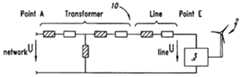
- FIG. 8shows an equivalent circuit diagram of an electrical network with a transformer and an electrical overhead line (a) to which an electrical generator of a wind power installation is connected, as well as vector diagrams (b to e) representing various operating conditions,
- FIG. 9shows a schematic circuit diagram of an arrangement for compensating for harmonic currents in a tap line
- FIG. 10shows a schematic circuit diagram of an arrangement for compensating for harmonic currents in an electrical network.
- FIGS. 1 to 3show various voltage and current configurations.
- FIG. 1shows a situation in which there is no reactive power, that is to say voltage U and current 1 are not phase-shifted. The current neither leads nor trails the voltage. There is therefore no fundamental oscillation reactive power.
- FIG. 2shows the situation in which the current I trails the voltage U in respect of time.
- inductive reactive poweris required, which is the case with most electrical consumers as they—such as for example electric motors have inductors.
- FIG. 3shows the situation in which the current I leads the voltage U in respect of time. Capacitive reactive power is required in this case.
- FIG. 4shows an oscillation in the reactive power.
- FIG. 5shows the harmonic component from the current configuration of FIG. 4 .
- FIG. 6shows an arrangement in which a wind power installation 2 is connected to a network spur. Consumers 6 are connected from the beginning (point A) to the end (point E) of the network spur or the electrical line 4 . If the wind power installation 2 is not feeding into the network, the voltage drops increasingly from the beginning (point A) to the end (point E) of the line 4 ; the voltage at the point E and the most closely adjacent last consumer 6 is thus lower than at the point A and the first consumer 6 which is most closely adjacent to that point A, on that electrical line 4 . If now the wind power installation 2 or a larger wind park is connected at the end of the electrical line 4 at point E in FIG. 6 and current is fed into the electrical line 4 the connection voltage at the point E of the electrical line 4 rises in an extreme fashion. The situation which occurs is now the reverse of the case without the wind power installation 2 connected at the end of the electrical line 4 .
- ground cablesgenerally represent a damped capacitor. In that respect attention is directed to the equivalent circuit diagram of a line, as shown in FIG. 7 .
- the voltage at the feed-in pointcan be regulated by means of reactive power regulation at the wind power installation.
- an inverteris used for that purpose.
- FIG. 8 ashows an equivalent circuit diagram wherein the electrical generator 3 of the wind power installation 2 is connected by way of a line and a transformer to an electrical network (not shown) which is usually a fixed network.
- FIGS. 8 b to 8 eshow vector diagrams in relation to various operating conditions.
- the generator 3 of the wind power installation 2only feeds active power into the electrical network 10 ; it can be seen immediately that the voltage U line at the feed-in point (point E) is higher than the voltage U network at the point A.
- a component of inductive reactive poweris fed into the network in addition to the active power and it can be seen that the voltages U line and U network at the end at point E and at the beginning point A are equal.
- the case C shown in FIG. 8 dillustrates in comparison that too much inductive reactive power is being fed into the network; the consequence of this is that the voltage U line at the point E becomes too low.
- the case D in FIG. 8 eshows the situation when excessive capacitive reactive power is being fed into the network; consequently the voltage U line at the feed-in point/point E rises very greatly in relation to the voltage U network . The latter situation absolutely has to be avoided.
- an inverter(not shown) is connected between the generator 3 and the point E as shown in FIG. 8 a .
- the function of such an inverteris to exactly follow a predetermined voltage value insofar as the cos ⁇ of the output current is correspondingly rapidly and dynamically regulated.
- harmonic reactive powersoccur in the electrical network. More specifically, electrical consumers increasingly require a current which includes harmonics or produce harmonics in the electrical network, such as for example television units which at the input have a rectifier or industrial operations which operate regulated rectifier drives.
- FIG. 4shows a situation in which harmonic reactive power is required.
- the voltage configuration Uis virtually sinusoidal while the current 1 , besides the fundamental oscillation, also includes harmonics. It is possible to clearly see here the fifth harmonic.
- FIG. 5shows the required fifth harmonic as a separate component In of the current 1 .
- FIG. 9shows a tap line 11 which is connected with its one end (at the left in FIG. 9 ) to an electrical network (not shown) while consumers 6 are connected to the other end thereof (at the right in FIG. 9 ).
- a tap line 11can for example supply an industrial area or park or one or more villages with electric current.
- the current flowing to the consumers 6is measured by means of a current transformer 12 .
- the measurement signal from the transformer 12is passed to an evaluation circuit 14 which continuously analyses on-line which current harmonics are contained in the current on the tap line 11 . That measurement results serves as a reference value which is fed as an output signal to an inverter 16 which then produces substantially at the same time the required harmonics and feeds same into the electrical line 11 upstream of the transformer 12 . That ensures that the required harmonics reactive power is produced by the inverter 16 for compensation of the harmonic reactive power present in the electrical network, and is not taken from the electrical network.
- FIG. 10diagrammatically shows the electrical network 10 whose voltage is measured by means of a voltage transformer 18 .
- the measurement signal from the voltage transformer 18is fed to an evaluation device 20 .
- the output signal of the voltage device 20is deducted by a subtracting device 24 from the output signal of the reference value device 22 and the difference output signal, resulting therefrom, from the subtracting device 24 is fed to the inverter 10 which then substantially at the same time produces the required harmonics in order to compensate for the harmonic reactive power in the electrical network.
- the network voltageis measured by means of the voltage transformer 18 and the evaluation device 20 serves to detect which harmonics are contained in the voltage configuration.
- the harmonic currents in the electrical network 10produce at the network impedance voltage drops corresponding to the frequency and amplitude thereof.
- the values which are measured and calculated in that wayare predetermined for the inverter 16 as current reference values.
- the inverter 16then, produces, in accordance with the reference values, the current harmonics with the required frequencies, amplitudes and phase positions.
Landscapes
- Engineering & Computer Science (AREA)
- Power Engineering (AREA)
- Supply And Distribution Of Alternating Current (AREA)
- Control Of Eletrric Generators (AREA)
- Control Of Electrical Variables (AREA)
- Diaphragms For Electromechanical Transducers (AREA)
- Wind Motors (AREA)
- Control Of Resistance Heating (AREA)
- Power Conversion In General (AREA)
Abstract
Description
The invention concerns a method of reactive power regulation in an electrical network, in which electrical power is produced by an electrical generator preferably driven by the rotor of a wind power installation and suitably modulated by means of a compensation device between the generator and the network for the compensation of reactive power. The invention further concerns an apparatus for producing electrical energy in an electrical network, comprising an electrical generator preferably driven by the rotor of a wind power installation and a compensation device between the generator and the network for the compensation of reactive power.
Many consumers connected to the electrical network require inductive reactive power. Compensation of such an inductive reactive power component is effected by using capacitors which are also referred to as phase-shifting capacitors whose capacitive reactance is approximately as high as the inductive reactance. Complete compensation of the inductive reactive power by means of phase-shifting capacitors is however not possible in practice precisely when high power fluctuations are involved. A further disadvantage is that the phase-shifting capacitors required, which are frequently combined together to form what is referred to as capacitor batteries and which moreover take up a great deal of space have a negative effect on the stability of the electrical network.
The object of the present invention is to compensate for the reactive power in an electrical network in a simple fashion.
In a method and an apparatus of the kind set forth in the opening part of this specification, that object is attained in that the compensation device is so regulated that the electrical power delivered to the consumer has a reactive power component which is adapted in respect of its phase, amplitude and/or frequency to the consumer in such a way as to compensate for the reactive power in the consumer.
In accordance with the invention, by means of the compensation device, a reactive power is ‘produced’, which is in a position to compensate for the reactive power in the consumer. For example, by means of the compensation device according to the invention, it is possible to produce a capacitive reactive power component which is adapted to the inductive reactive power component required by the consumer, in such a way that it substantially completely compensates for the inductive reactive power component in the consumer. The advantage of the invention is thus essentially that there is provided a regulating system which rapidly reacts in particular to frequently occurring high power fluctuations, so that complete reactive power compensation is substantially maintained. Accordingly, inductive or capacitive reactive power can be fed selectively into the electrical network, which in accordance with the invention is implemented by regulation of the compensation device.
In this respect, by means of the regulation in accordance with the invention, it is preferably also possible for the electrical power produced to be of a frequency which corresponds to the frequency of the consumer or also represents a multiple of the consumer frequency. In the former case accordingly reactive power can be supplied at the frequency of the consumer or the network frequency of the electrical network. In the latter case for example as desired harmonic reactive power can be fed into the electrical network. For example the fifth harmonic can be fed into the network, at a frequency of 250 Hz, as a capacitive harmonic. That then compensates for the harmonic reactive power of electrical consumers which are connected to the electrical network such as for example televisions, energy-saving lamps and so forth.
Desirably the compensation device has an inverter with which phase, amplitude and/or frequency of the voltage and/or current characteristics can be particularly easily adjusted or regulated in order to produce a reactive power component which is suitable for appropriately compensating for the reactive power in the consumer.
Preferably the compensation device has a measuring device for detecting the voltage and/or current variations in the electrical network, preferably at the feed-in point. In a development of the embodiment in which the compensation device includes an inverter the compensation device controls the inverter in dependence on the measurement results of the measuring device.
The voltage produced by the electrical generator is preferably regulated substantially to a predetermined reference value with suitable adaptation of the reactive power component in the electrical power delivered to the consumer. In that situation adaptation of the reactive power component can take place by suitable control of the power factor (cos φ) or the phase of the current produced by the electrical generator. If the electrical generator is connected to an electrical network by way of a line and/or a transformer then the voltage produced by the electrical generator is desirably so regulated that the value thereof is in the order of magnitude of the value of the network voltage or corresponds thereto. That avoids undesirably high or low voltages at the generator side. Usually the network voltage is substantially constant if it involves a substantially rigid network.
Preferred embodiments of the invention are described in greater detail hereinafter with reference to the accompanying drawings in which:
The occurrence of fundamental oscillation reactive powers in an electrical network has already long been known.FIGS. 1 to3 show various voltage and current configurations.
For the situation where the electrical line is in the form of a free or overhead line (no ground cable), such a line in fact essentially represents an inductor. In comparison ground cables generally represent a damped capacitor. In that respect attention is directed to the equivalent circuit diagram of a line, as shown in FIG.7.
The voltage at the feed-in point (point E inFIG. 6 ) can be regulated by means of reactive power regulation at the wind power installation. Preferably an inverter is used for that purpose.
To provide for reactive power compensation an inverter (not shown) is connected between thegenerator 3 and the point E as shown inFIG. 8 a. Now the function of such an inverter is to exactly follow a predetermined voltage value insofar as the cos φ of the output current is correspondingly rapidly and dynamically regulated.
In addition harmonic reactive powers occur in the electrical network. More specifically, electrical consumers increasingly require a current which includes harmonics or produce harmonics in the electrical network, such as for example television units which at the input have a rectifier or industrial operations which operate regulated rectifier drives.FIG. 4 shows a situation in which harmonic reactive power is required. The voltage configuration U is virtually sinusoidal while the current1, besides the fundamental oscillation, also includes harmonics. It is possible to clearly see here the fifth harmonic.FIG. 5 shows the required fifth harmonic as a separate component In of the current1.
Such harmonics in the current configuration (current harmonics) cause in the electrical network voltage harmonics which adversely affect the quality of the voltage in the electrical network. It is therefore necessary for such harmonic reactive powers also to be compensated.
Claims (37)
1. A method of reactive power regulation in an electrical network, comprising:
producing electrical power by an electrical generator driven by the rotor of a wind power installation and modulating the power by means of a compensation device between the generator and the network for the compensation of reactive power by adaptation of the phase and/or amplitude of the reactive power component of the delivered electrical power, and
regulating the compensation device so that the electrical power delivered to the consumer has a reactive power component that is adapted in respect of its phase and/or amplitude and in respect of its frequency to the consumer to compensate for the harmonic reactive power in the consumer.
2. The method according toclaim 1 wherein the compensation device is so regulated that the electrical generator produces capacitive reactive power in order to compensate for the inductive reactive power in the consumer.
3. The method according toclaim 1 wherein the delivered electrical power is of a frequency which corresponds to the frequency of the reactive power caused by the consumer or represents a multiple of said frequency.
4. The method according to at least one ofclaim 1 wherein the compensation device operates as an inverter.
5. The method according toclaim 1 wherein the compensation device measures the voltage and/or current configurations in the electrical network, preferably at the feed-in point of the electrical power into the network, and in dependence on the measurement results regulates the reactive power component in the electrical power produced by the electrical generator.
6. The method according toclaim 1 wherein the voltage produced by the electrical generator is regulated substantially to a predetermined reference value with suitable adaptation of the reactive power component in the electrical power delivered to the consumer.
7. The method according toclaim 6 wherein adaptation of the reactive power component is effected by suitable control of the power factor (cos φ) or the phase of the current produced by the electrical generator.
8. The method according toclaim 6 in which the electrical generator is connected to an electrical network by way of a line and/or a transformer, further including the step of:
regulating the voltage produced by the electrical generator so that the value thereof is of the order of magnitude of the value of the network voltage or corresponds to the value of the network voltage.
9. An apparatus for producing electrical energy in an electrical network, comprising:
an electrical generator;
a compensation device between the generator and the network, the compensation device adapted to compensate for the reactive power by adaptation of the phase and/or amplitude of the reactive power component of the delivered electrical power; and
a regulating device configured to regulate the compensation device in such a way that the electrical power delivered to the consumer has a reactive power component that is adapted in respect of its phase and/or amplitude and in respect of its frequency to the consumer to compensate for the harmonic reactive power in the consumer.
10. The apparatus according toclaim 9 wherein the regulating device regulates the compensation device in such a way that the electrical generator produces capacitive reactive power in order to compensate for the inductive reactive power in the consumer.
11. The apparatus according toclaim 9 wherein the delivered electrical power is of a frequency which corresponds to the frequency of the reactive power caused by the consumer and represents a multiple of said frequency.
12. The apparatus according toclaim 9 wherein the compensation device has an inverter.
13. The apparatus according toclaim 9 wherein the regulating device has a measuring device for detecting the voltage and/or current configurations in the electrical network, preferably at the feed-in point of the electrical power into the network.
14. The apparatus according toclaim 12 wherein the regulating device controls the inverter in dependence on the measurement results of the measuring device.
15. The apparatus according toclaim 9 wherein the regulating device regulates the voltage produced by the electrical generator substantially to a predetermined reference value by control of the reactive power component in the electrical power delivered to the consumer.
16. The apparatus according toclaim 15 wherein the regulating device effects adaptation of the reactive power component by suitable control of the power factor (cos φ) or the phase of the current delivered by the electrical generator.
17. The apparatus according toclaim 15 wherein the electrical generator is connected to an electrical network by way of a line and/or a transformer characterised in that the regulating device regulates the voltage produced by the electrical generator in such a way that the value thereof is of the order of magnitude of the value of the network voltage or corresponds to the value of the network voltage.
18. A method of reactive power regulation in an electrical network comprising the steps of:
producing electrical power by an electrical generator, preferably driven by the rotor of a wind power installation;
modulating the electrical power by means of a compensation device between the generator and the electrical network for the compensation of reactive power by adaption of the phase and/or amplitude of the reactive power component of the delivered electrical power;
measuring the voltage and/or current configurations in the electrical network, preferably at a feed-in point of the electrical power into the network; and
regulating the compensation device in dependence on the measurement results such that the electrical power delivered to the consumer has a reactive power component which is adapted in respect of its phase and/or amplitude and in respect of its frequency to the consumer to compensate for the harmonic reactive power in the consumer.
19. A method of reactive power regulation in an electrical network comprising the steps of:
producing electrical power by an electrical generator, preferably driven by the rotor of a wind power installation;
modulating the electrical power by means of a compensation device between the generator and the electrical network for the compensation of reactive power by adaption of the phase and/or amplitude of the reactive power component of the delivered electrical power;
regulating the compensation device such that the electrical power delivered to the consumer has a reactive power component which is adapted in respect of its phase and/or amplitude and in respect of its frequency to the consumer to compensate for the reactive power in the consumer by regulating the voltage produced by the electrical generator substantially to a predetermined reference value with suitable adaptation of the harmonic reactive power component in the electrical power delivered to the consumer.
20. The method according toclaim 18 wherein the compensation device is so regulated that the electrical generator produces capacitive reactive power in order to compensate for the inductive reactive power in the consumer.
21. The method ofclaim 18 wherein the delivered electrical power is of a frequency which corresponds to the frequency of the reactive power caused by the consumer or represents a multiple of said frequency.
22. The method ofclaim 18 wherein the compensation device operates as an inverter.
23. The method ofclaim 18 wherein the current configurations in the electrical network are measured and that the measured signals are continuously analyzed which harmonics are contained therein serving as a reference signal for the compensation device producing the required harmonics to be fed into the electrical network.
24. The method ofclaim 18 wherein the voltage configurations in the electrical network are measured, that the measured signals are subtracted from a reference signal and that the difference signal is fed to the compensation device producing the required harmonics to be fed into the electrical network.
25. The method ofclaim 24 wherein adaptation of the reactive power component is effected by suitable control of the power factor (cos φ) or the phase of the current produced by the electrical generator.
26. The method ofclaim 25 wherein the electrical generator is connected to an electrical network by way of a line and/or a transformer, and wherein the voltage produced by the electrical generator is so regulated that the value thereof is of the order of magnitude of the value of the network voltage or corresponds to the value of the network voltage.
27. An apparatus for producing electrical energy in an electrical network comprising:
an electrical generator, preferably driven by the rotor of a wind power installation,
a compensation device between the generator and the network for the compensation of reactive power by adaption of the phase and/or amplitude of the reactive power component of the delivered electrical power,
a measuring device for measuring the voltage and/or current configurations in the electrical network, preferably at the feed-in point of the electrical power into the network, and
a regulating device for regulating the compensation device in dependence on the measurement results in such a way that the electrical power delivered to the consumer has a reactive power component which is adapted in respect of its phase and/or amplitude and in respect of its frequency to the consumer to compensate for the harmonic reactive power in the consumer.
28. An apparatus for producing electrical energy in an electrical network comprising:
an electrical generator, preferably driven by the rotor of a wind power installation,
a compensation device between the generator and the network for the compensation of reactive power by adaption of the phase and/or amplitude of the reactive power component of the delivered electrical power, and
a regulating device for regulating the compensation device in such a way that the electrical power delivered to the consumer has a reactive power component which is adapted in respect of its phase and/or amplitude and in respect of its frequency to the consumer to compensate for the reactive power in the consumer by regulating the voltage produced by the electrical generator substantially to a predetermined reference value with suitable adaptation of the harmonic reactive power component in the electrical power delivered to the consumer.
29. The apparatus ofclaim 28 wherein the regulating device regulates the compensation device in such a way that the electrical generator produces capacitive reactive power in order to compensate for the inductive reactive power in the consumer.
30. The apparatus ofclaim 29 wherein the delivered electrical power is of a frequency which corresponds to the frequency of the reactive power caused by the consumer and represents a multiple of said frequency.
31. The apparatus ofclaim 30 wherein the compensation device has an inverter.
32. The apparatus ofclaim 31 wherein the regulating device has a measuring device for detecting the current configurations in the electrical network and an evaluation device for continuously analyzing which harmonics are contained therein serving as a reference signal for the compensation device producing the required harmonics to be fed into the electrical network.
33. The apparatus ofclaim 32 wherein the regulating device controls the inverter in dependence on the measurement results of the measuring device.
34. The apparatus ofclaim 33 wherein the regulating device has a measuring device for detecting the voltage configurations in the electrical network and a subtracting device for subtracting the measured signals from a reference signal wherein the difference signal is fed to the compensation device producing the required harmonics to be fed into the electrical network.
35. The apparatus ofclaim 34 wherein the regulating device effects adaptation of the reactive power component by suitable control of the power factor (cos φ) or the phase of the current delivered by the electrical generator.
36. The apparatus ofclaim 35 wherein the electrical generator is connected to an electrical network by way of a line and/or a transformer and wherein the regulating device regulates the voltage produced by the electrical generator in such a way that the value thereof is of the order of magnitude of the value of the network voltage or corresponds to the value of the network voltage.
37. A wind power installation comprising an apparatus as claimed inclaim 27 .
Applications Claiming Priority (3)
| Application Number | Priority Date | Filing Date | Title |
|---|---|---|---|
| DE19943847 | 1999-09-13 | ||
| DE10020635ADE10020635A1 (en) | 1999-09-13 | 2000-04-27 | Process for controlling reactive power and device for generating electrical energy in an electrical network |
| PCT/EP2000/008745WO2001020745A1 (en) | 1999-09-13 | 2000-09-07 | Method for controlling the reactive power and device for generating electrical energy in an electrical network |
Publications (1)
| Publication Number | Publication Date |
|---|---|
| US6924627B1true US6924627B1 (en) | 2005-08-02 |
Family
ID=26005491
Family Applications (1)
| Application Number | Title | Priority Date | Filing Date |
|---|---|---|---|
| US10/088,011Expired - LifetimeUS6924627B1 (en) | 1999-09-13 | 2000-09-07 | Method of reactive power regulation and aparatus for producing electrical energy in an electrical network |
Country Status (17)
| Country | Link |
|---|---|
| US (1) | US6924627B1 (en) |
| EP (1) | EP1224721B1 (en) |
| JP (2) | JP4002763B2 (en) |
| CN (1) | CN100420117C (en) |
| AT (1) | ATE305664T1 (en) |
| AU (1) | AU760758B2 (en) |
| BR (1) | BR0013946A (en) |
| CA (1) | CA2387113C (en) |
| CY (1) | CY1106054T1 (en) |
| DE (1) | DE50011261D1 (en) |
| DK (1) | DK1224721T3 (en) |
| ES (1) | ES2248113T3 (en) |
| MX (1) | MXPA02002626A (en) |
| NO (1) | NO323763B1 (en) |
| PL (1) | PL205886B1 (en) |
| TR (1) | TR200200656T2 (en) |
| WO (1) | WO2001020745A1 (en) |
Cited By (15)
| Publication number | Priority date | Publication date | Assignee | Title |
|---|---|---|---|---|
| US20060152010A1 (en)* | 1997-12-19 | 2006-07-13 | Aloys Wobben | Method of operating a wind power installation and a wind power installation |
| US20070108769A1 (en)* | 2003-05-05 | 2007-05-17 | Aloys Wobben | Operating method for a wind park |
| US20080004721A1 (en)* | 2004-06-25 | 2008-01-03 | Emerson Process Management Power & Water Solutions, Inc. | Method and Apparatus for Providing Economic Analysis of Power Generation and Distribution |
| US20080106099A1 (en)* | 2006-11-02 | 2008-05-08 | Masaya Ichinose | Wind Power Generation Apparatus, Wind Power Generation System and Power System Control Apparatus |
| US20080150283A1 (en)* | 2006-12-22 | 2008-06-26 | Ingeteam, S.A. | Reactive power control for operating a wind farm |
| US20090079191A1 (en)* | 2007-09-26 | 2009-03-26 | General Electric Company | Electric power generation with magnetically geared machine |
| US20100117606A1 (en)* | 2005-10-27 | 2010-05-13 | Hitachi, Ltd. | Distributed generation system and power system stabilizing method |
| US20100329652A1 (en)* | 2008-02-01 | 2010-12-30 | Isis Innovation Ltd. | Electricity generator |
| US8247917B2 (en)* | 2010-11-25 | 2012-08-21 | Mitsubishi Heavy Industries, Ltd. | Storage battery output power control method for wind turbine generator |
| US8648499B2 (en) | 2011-01-27 | 2014-02-11 | General Electric Company | Systems, methods, and apparatus for accelerating volt/VAR load flow optimization |
| CN103701132A (en)* | 2013-12-20 | 2014-04-02 | 清华大学 | Method for controlling overvoltage of active power distribution network on basis of active-reactive coordination |
| US8816531B2 (en) | 2011-01-27 | 2014-08-26 | General Electric Company | Systems, methods, and apparatus for integrated volt/VAR control in power distribution networks |
| US8941961B2 (en) | 2013-03-14 | 2015-01-27 | Boulder Wind Power, Inc. | Methods and apparatus for protection in a multi-phase machine |
| US9118213B2 (en) | 2010-11-24 | 2015-08-25 | Kohler Co. | Portal for harvesting energy from distributed electrical power sources |
| DE102015112155A1 (en) | 2015-07-24 | 2017-01-26 | Wobben Properties Gmbh | Method and device for detecting an electrical voltage in a supply network |
Families Citing this family (6)
| Publication number | Priority date | Publication date | Assignee | Title |
|---|---|---|---|---|
| EP2275674B2 (en) | 2001-09-28 | 2023-09-06 | Wobben Properties GmbH | Method for operating a wind park |
| DE102004048339A1 (en) | 2004-10-01 | 2006-04-13 | Repower Systems Ag | Wind energy plant with converter control and method of operation |
| CN100399667C (en)* | 2005-08-10 | 2008-07-02 | 蒋建民 | Generator reactive power regulator and regulating process thereof |
| EP2482418B1 (en)* | 2011-02-01 | 2018-08-22 | Siemens Aktiengesellschaft | Active desynchronization of switching converters |
| DE102013218645B3 (en)* | 2013-09-17 | 2015-01-22 | Senvion Se | Method and arrangement for determining the electrical properties of a wind energy plant |
| CN110336301B (en)* | 2019-07-01 | 2020-09-11 | 东北电力大学 | Wind storage system auxiliary power grid primary frequency modulation capacity configuration method based on series-parallel structure |
Citations (69)
| Publication number | Priority date | Publication date | Assignee | Title |
|---|---|---|---|---|
| US2652529A (en)* | 1952-09-17 | 1953-09-15 | Gen Electric | Phase balancing system |
| US3400326A (en)* | 1965-12-28 | 1968-09-03 | Zhukov Leonid Alexeevich | Device for automatic reactive power regulation in electric networks |
| US3754184A (en)* | 1972-06-21 | 1973-08-21 | Harnischfeger Corp | Reactive power compensation control system |
| US3829759A (en)* | 1973-01-18 | 1974-08-13 | Asea Ab | Means for generating reactive power |
| US3900792A (en)* | 1973-01-05 | 1975-08-19 | Siemens Ag | Method and apparatus for generating reactive power |
| US3936727A (en)* | 1973-10-12 | 1976-02-03 | General Electric Company | High speed control of reactive power for voltage stabilization in electric power systems |
| US3963978A (en)* | 1975-02-14 | 1976-06-15 | General Electric Company | Reactive power compensator |
| US3968422A (en)* | 1974-03-27 | 1976-07-06 | Siemens Aktiengesellschaft | Method and apparatus for the static compensation of reactive power |
| US3968432A (en)* | 1973-10-12 | 1976-07-06 | General Electric Company | Remote voltage sensor for power system regulation |
| US3983469A (en)* | 1975-02-03 | 1976-09-28 | Lorain Products Corporation | Controlled reactance regulator circuit |
| US3999117A (en)* | 1974-12-23 | 1976-12-21 | Westinghouse Electric Corporation | Method and control apparatus for static VAR generator and compensator |
| US4019124A (en)* | 1975-03-25 | 1977-04-19 | Siemens Aktiengesellschaft | Apparatus for compensating reactive power in a three-phase network |
| US4028614A (en)* | 1976-05-03 | 1977-06-07 | General Electric Company | High speed control of reactive power for voltage stabilization in electric power systems |
| US4110631A (en)* | 1974-07-17 | 1978-08-29 | Wind Power Systems, Inc. | Wind-driven generator |
| US4242628A (en)* | 1978-05-30 | 1980-12-30 | The Regents Of The University Of Minnesota | Wind energy conversion system |
| US4299198A (en)* | 1979-09-17 | 1981-11-10 | Woodhull William M | Wind power conversion and control system |
| US4315163A (en)* | 1980-09-16 | 1982-02-09 | Frank Bienville | Multipower electrical system for supplying electrical energy to a house or the like |
| US4349744A (en)* | 1976-07-09 | 1982-09-14 | Westinghouse Electric Corp. | System for operating multiple gas turbines for coordinated dead load pickup |
| US4366387A (en)* | 1979-05-10 | 1982-12-28 | Carter Wind Power | Wind-driven generator apparatus and method of making blade supports _therefor |
| US4400659A (en)* | 1980-05-30 | 1983-08-23 | Benjamin Barron | Methods and apparatus for maximizing and stabilizing electric power derived from wind driven source |
| US4409050A (en)* | 1979-05-10 | 1983-10-11 | Carter Wind Power | Method of making blade supports |
| US4445049A (en)* | 1981-12-28 | 1984-04-24 | General Electric Company | Inverter for interfacing advanced energy sources to a utility grid |
| US4451777A (en) | 1981-09-10 | 1984-05-29 | Westinghouse Electric Corp. | Static VAR generation for transmission line compensation |
| US4570214A (en)* | 1984-03-29 | 1986-02-11 | Tokyo Shibaura Denki Kabushiki Kaisha | Reactive power control cycloconverter |
| US4590416A (en)* | 1983-08-08 | 1986-05-20 | Rig Efficiency, Inc. | Closed loop power factor control for power supply systems |
| US4647837A (en)* | 1983-10-12 | 1987-03-03 | Bbc Brown, Boveri & Company, Limited | Reactive-power compensator for compensating a reactive-current component in an alternating-voltage system |
| US4677364A (en)* | 1985-01-04 | 1987-06-30 | The United States Of America As Represented By The United States Department Of Energy | Reactive power compensating system |
| US4695736A (en)* | 1985-11-18 | 1987-09-22 | United Technologies Corporation | Variable speed wind turbine |
| US4752726A (en)* | 1986-09-09 | 1988-06-21 | Kabushiki Kaisha Toshiba | Reactive power compensation device |
| DE3818732A1 (en) | 1988-06-01 | 1989-12-07 | Siemens Ag | METHOD AND DEVICE FOR COMPENSATING BLIND CURRENTS |
| US5138247A (en)* | 1990-09-18 | 1992-08-11 | Kabushiki Kaisha Toshiba | Reactive power compensating apparatus with higher harmonic suppressing function |
| WO1992014298A1 (en) | 1991-02-01 | 1992-08-20 | U.S. Windpower, Inc. | Variable speed wind turbine |
| US5148362A (en)* | 1990-08-16 | 1992-09-15 | Siemens Aktiengesellschaft | Method and device for balancing a three-phase system |
| JPH04289732A (en) | 1991-03-19 | 1992-10-14 | Toshiba Corp | reactive power compensator |
| US5166597A (en)* | 1991-08-08 | 1992-11-24 | Electric Power Research Institute | Phase-shifting transformer system |
| US5329221A (en)* | 1992-08-12 | 1994-07-12 | Electric Power Research Institute | Advanced static var compensator control system |
| US5343139A (en)* | 1992-01-31 | 1994-08-30 | Westinghouse Electric Corporation | Generalized fast, power flow controller |
| US5428283A (en)* | 1994-05-26 | 1995-06-27 | Alliedsignal Inc. | Power factor control of pulse width modulated inverter supplied permanent magnet motor |
| US5466973A (en)* | 1992-04-29 | 1995-11-14 | N.V. Geb Zuid-Holland West | Delivery point voltage regulation in electric energy distribution networks |
| US5469044A (en)* | 1995-01-05 | 1995-11-21 | Westinghouse Electric Corporation | Transmission line power flow controller with unequal advancement and retardation of transmission angle |
| US5513090A (en) | 1994-11-15 | 1996-04-30 | Electric Power Research Institute, Inc. | Hybrid series active, parallel passive, power line conditioner for harmonic isolation between a supply and a load |
| US5548504A (en)* | 1992-10-19 | 1996-08-20 | Canon Kabushiki Kaisha | Power line linking apparatus for linking a power generator to a commercial power line |
| US5604420A (en)* | 1994-11-30 | 1997-02-18 | Mitsubishi Denki Kabushiki Kaisha | Stabilizer for power system |
| US5637985A (en)* | 1991-12-25 | 1997-06-10 | Mazda Motor Corporation | Alternator control system |
| US5698968A (en)* | 1994-11-15 | 1997-12-16 | Kabushiki Kaisha Toshiba | Power system stabilizer for generator |
| US5734257A (en)* | 1994-07-22 | 1998-03-31 | Electric Power Research Institute, Inc. | Transmission line power controller with a continuously controllable voltage source responsive to a real power demand and a reactive power demand |
| US5734586A (en)* | 1995-05-05 | 1998-03-31 | Cornell Research Foundation, Inc. | System for achieving optimal steady state in power distribution networks |
| US5736838A (en)* | 1993-12-07 | 1998-04-07 | Dove; Donald C. | High speed power factor controller |
| US5793593A (en)* | 1994-02-07 | 1998-08-11 | New York State Electric & Gas Corporation | Method and apparatus using a five-wire network for distribution of electrical power |
| US5808880A (en)* | 1996-08-30 | 1998-09-15 | Otis Elevator Company | Power factor controller for active converter |
| US5841267A (en)* | 1995-04-21 | 1998-11-24 | General Electric Co. | Power flow control with rotary transformers |
| JPH114543A (en) | 1997-06-11 | 1999-01-06 | Meidensha Corp | Restricting apparatus of variation in inrush current output of induction generator |
| US5892664A (en)* | 1997-01-10 | 1999-04-06 | Vedder; Dietrich | Inverter for connecting a variable voltage power source to a utility grid |
| US6051941A (en)* | 1999-03-03 | 2000-04-18 | P.C. Krause & Associates, Inc. | Nonlinear stabilizing control for power electronic based systems |
| US6107784A (en)* | 1996-12-26 | 2000-08-22 | Kabushiki Kaisha Toshiba | System interconnection protective device for non-utility generation equipment |
| US6137187A (en)* | 1997-08-08 | 2000-10-24 | Zond Energy Systems, Inc. | Variable speed wind turbine generator |
| US6265852B1 (en)* | 1999-04-14 | 2001-07-24 | Mitsubishi Denki Kabushiki Kaisha | Excitation controller and excitation control method for stabilizing voltage in electric power system |
| US6323618B1 (en)* | 2000-02-28 | 2001-11-27 | Mitsubishi Denki Kabushiki Kaisha | Excitation controller and excitation control method for stabilizing voltage in electric power system |
| US6338009B1 (en)* | 1997-10-22 | 2002-01-08 | Hitachi, Ltd. | Method and apparatus for estimating frequency characteristics of power system, and application thereof |
| US6397157B1 (en)* | 1999-07-02 | 2002-05-28 | General Electric Company | Method and apparatus for real time measurement of three phase electrical parameters |
| US6573691B2 (en)* | 2001-10-17 | 2003-06-03 | Hatch Associates Ltd. | Control system and method for voltage stabilization in electric power system |
| US6605880B1 (en)* | 2000-08-01 | 2003-08-12 | Navitas Energy, Inc. | Energy system providing continual electric power using wind generated electricity coupled with fuel driven electrical generators |
| US6628103B2 (en)* | 2001-03-30 | 2003-09-30 | Mitsubishi Heavy Industries, Ltd. | Power factor control apparatus and method |
| US6670721B2 (en)* | 2001-07-10 | 2003-12-30 | Abb Ab | System, method, rotating machine and computer program product for enhancing electric power produced by renewable facilities |
| US6671585B2 (en)* | 2000-12-29 | 2003-12-30 | Abb Ab | System, method and computer program product for enhancing commercial value of electrical power produced from a renewable energy power production facility |
| US6784564B1 (en)* | 1997-12-19 | 2004-08-31 | Alovs Wobben | Method of operating a wind power installation and a wind power installation |
| US6794855B2 (en)* | 2001-09-21 | 2004-09-21 | Mitsubishi Denki Kabushiki Kaisha | Voltage stabilization control method and voltage stabilization control apparatus |
| US6806688B2 (en)* | 2001-05-10 | 2004-10-19 | Kabushiki Kaisha Toshiba | Difference power adjustment apparatus having a capacitor and reactor connected power-system bus |
| US6825640B1 (en)* | 2001-11-30 | 2004-11-30 | Rolls-Royce Plc | Generator arrangements |
- 2000
- 2000-09-07ESES00960619Tpatent/ES2248113T3/ennot_activeExpired - Lifetime
- 2000-09-07CNCNB008147485Apatent/CN100420117C/ennot_activeExpired - Lifetime
- 2000-09-07CACA002387113Apatent/CA2387113C/ennot_activeExpired - Lifetime
- 2000-09-07AUAU72849/00Apatent/AU760758B2/ennot_activeCeased
- 2000-09-07EPEP00960619Apatent/EP1224721B1/ennot_activeRevoked
- 2000-09-07MXMXPA02002626Apatent/MXPA02002626A/enactiveIP Right Grant
- 2000-09-07DEDE50011261Tpatent/DE50011261D1/ennot_activeExpired - Lifetime
- 2000-09-07JPJP2001524207Apatent/JP4002763B2/ennot_activeExpired - Fee Related
- 2000-09-07DKDK00960619Tpatent/DK1224721T3/enactive
- 2000-09-07USUS10/088,011patent/US6924627B1/ennot_activeExpired - Lifetime
- 2000-09-07ATAT00960619Tpatent/ATE305664T1/enactive
- 2000-09-07PLPL353934Apatent/PL205886B1/enunknown
- 2000-09-07WOPCT/EP2000/008745patent/WO2001020745A1/enactiveIP Right Grant
- 2000-09-07BRBR0013946-7Apatent/BR0013946A/ennot_activeApplication Discontinuation
- 2000-09-07TRTR2002/00656Tpatent/TR200200656T2/enunknown
- 2002
- 2002-03-12NONO20021210Apatent/NO323763B1/enactiveIP Right Review Request
- 2005
- 2005-11-24JPJP2005338970Apatent/JP2006115692A/enactivePending
- 2005-12-23CYCY20051101597Tpatent/CY1106054T1/enunknown
Patent Citations (70)
| Publication number | Priority date | Publication date | Assignee | Title |
|---|---|---|---|---|
| US2652529A (en)* | 1952-09-17 | 1953-09-15 | Gen Electric | Phase balancing system |
| US3400326A (en)* | 1965-12-28 | 1968-09-03 | Zhukov Leonid Alexeevich | Device for automatic reactive power regulation in electric networks |
| US3754184A (en)* | 1972-06-21 | 1973-08-21 | Harnischfeger Corp | Reactive power compensation control system |
| US3900792A (en)* | 1973-01-05 | 1975-08-19 | Siemens Ag | Method and apparatus for generating reactive power |
| US3829759A (en)* | 1973-01-18 | 1974-08-13 | Asea Ab | Means for generating reactive power |
| US3936727A (en)* | 1973-10-12 | 1976-02-03 | General Electric Company | High speed control of reactive power for voltage stabilization in electric power systems |
| US3968432A (en)* | 1973-10-12 | 1976-07-06 | General Electric Company | Remote voltage sensor for power system regulation |
| US3968422A (en)* | 1974-03-27 | 1976-07-06 | Siemens Aktiengesellschaft | Method and apparatus for the static compensation of reactive power |
| US4110631A (en)* | 1974-07-17 | 1978-08-29 | Wind Power Systems, Inc. | Wind-driven generator |
| US3999117A (en)* | 1974-12-23 | 1976-12-21 | Westinghouse Electric Corporation | Method and control apparatus for static VAR generator and compensator |
| US3983469A (en)* | 1975-02-03 | 1976-09-28 | Lorain Products Corporation | Controlled reactance regulator circuit |
| US3963978A (en)* | 1975-02-14 | 1976-06-15 | General Electric Company | Reactive power compensator |
| US4019124A (en)* | 1975-03-25 | 1977-04-19 | Siemens Aktiengesellschaft | Apparatus for compensating reactive power in a three-phase network |
| US4028614A (en)* | 1976-05-03 | 1977-06-07 | General Electric Company | High speed control of reactive power for voltage stabilization in electric power systems |
| US4349744A (en)* | 1976-07-09 | 1982-09-14 | Westinghouse Electric Corp. | System for operating multiple gas turbines for coordinated dead load pickup |
| US4242628A (en)* | 1978-05-30 | 1980-12-30 | The Regents Of The University Of Minnesota | Wind energy conversion system |
| US4409050A (en)* | 1979-05-10 | 1983-10-11 | Carter Wind Power | Method of making blade supports |
| US4366387A (en)* | 1979-05-10 | 1982-12-28 | Carter Wind Power | Wind-driven generator apparatus and method of making blade supports _therefor |
| US4299198A (en)* | 1979-09-17 | 1981-11-10 | Woodhull William M | Wind power conversion and control system |
| US4400659A (en)* | 1980-05-30 | 1983-08-23 | Benjamin Barron | Methods and apparatus for maximizing and stabilizing electric power derived from wind driven source |
| US4315163A (en)* | 1980-09-16 | 1982-02-09 | Frank Bienville | Multipower electrical system for supplying electrical energy to a house or the like |
| US4451777A (en) | 1981-09-10 | 1984-05-29 | Westinghouse Electric Corp. | Static VAR generation for transmission line compensation |
| US4445049A (en)* | 1981-12-28 | 1984-04-24 | General Electric Company | Inverter for interfacing advanced energy sources to a utility grid |
| US4590416A (en)* | 1983-08-08 | 1986-05-20 | Rig Efficiency, Inc. | Closed loop power factor control for power supply systems |
| US4647837A (en)* | 1983-10-12 | 1987-03-03 | Bbc Brown, Boveri & Company, Limited | Reactive-power compensator for compensating a reactive-current component in an alternating-voltage system |
| US4570214A (en)* | 1984-03-29 | 1986-02-11 | Tokyo Shibaura Denki Kabushiki Kaisha | Reactive power control cycloconverter |
| US4677364A (en)* | 1985-01-04 | 1987-06-30 | The United States Of America As Represented By The United States Department Of Energy | Reactive power compensating system |
| US4695736A (en)* | 1985-11-18 | 1987-09-22 | United Technologies Corporation | Variable speed wind turbine |
| US4752726A (en)* | 1986-09-09 | 1988-06-21 | Kabushiki Kaisha Toshiba | Reactive power compensation device |
| DE3818732A1 (en) | 1988-06-01 | 1989-12-07 | Siemens Ag | METHOD AND DEVICE FOR COMPENSATING BLIND CURRENTS |
| US5148362A (en)* | 1990-08-16 | 1992-09-15 | Siemens Aktiengesellschaft | Method and device for balancing a three-phase system |
| US5138247A (en)* | 1990-09-18 | 1992-08-11 | Kabushiki Kaisha Toshiba | Reactive power compensating apparatus with higher harmonic suppressing function |
| WO1992014298A1 (en) | 1991-02-01 | 1992-08-20 | U.S. Windpower, Inc. | Variable speed wind turbine |
| US5225712A (en) | 1991-02-01 | 1993-07-06 | U.S. Windpower, Inc. | Variable speed wind turbine with reduced power fluctuation and a static VAR mode of operation |
| JPH04289732A (en) | 1991-03-19 | 1992-10-14 | Toshiba Corp | reactive power compensator |
| US5166597A (en)* | 1991-08-08 | 1992-11-24 | Electric Power Research Institute | Phase-shifting transformer system |
| US5637985A (en)* | 1991-12-25 | 1997-06-10 | Mazda Motor Corporation | Alternator control system |
| US5343139A (en)* | 1992-01-31 | 1994-08-30 | Westinghouse Electric Corporation | Generalized fast, power flow controller |
| US5466973A (en)* | 1992-04-29 | 1995-11-14 | N.V. Geb Zuid-Holland West | Delivery point voltage regulation in electric energy distribution networks |
| US5329221A (en)* | 1992-08-12 | 1994-07-12 | Electric Power Research Institute | Advanced static var compensator control system |
| US5548504A (en)* | 1992-10-19 | 1996-08-20 | Canon Kabushiki Kaisha | Power line linking apparatus for linking a power generator to a commercial power line |
| US5736838A (en)* | 1993-12-07 | 1998-04-07 | Dove; Donald C. | High speed power factor controller |
| US5793593A (en)* | 1994-02-07 | 1998-08-11 | New York State Electric & Gas Corporation | Method and apparatus using a five-wire network for distribution of electrical power |
| US5428283A (en)* | 1994-05-26 | 1995-06-27 | Alliedsignal Inc. | Power factor control of pulse width modulated inverter supplied permanent magnet motor |
| US5734257A (en)* | 1994-07-22 | 1998-03-31 | Electric Power Research Institute, Inc. | Transmission line power controller with a continuously controllable voltage source responsive to a real power demand and a reactive power demand |
| US5698968A (en)* | 1994-11-15 | 1997-12-16 | Kabushiki Kaisha Toshiba | Power system stabilizer for generator |
| US5513090A (en) | 1994-11-15 | 1996-04-30 | Electric Power Research Institute, Inc. | Hybrid series active, parallel passive, power line conditioner for harmonic isolation between a supply and a load |
| US5604420A (en)* | 1994-11-30 | 1997-02-18 | Mitsubishi Denki Kabushiki Kaisha | Stabilizer for power system |
| US5469044A (en)* | 1995-01-05 | 1995-11-21 | Westinghouse Electric Corporation | Transmission line power flow controller with unequal advancement and retardation of transmission angle |
| US5841267A (en)* | 1995-04-21 | 1998-11-24 | General Electric Co. | Power flow control with rotary transformers |
| US5734586A (en)* | 1995-05-05 | 1998-03-31 | Cornell Research Foundation, Inc. | System for achieving optimal steady state in power distribution networks |
| US5808880A (en)* | 1996-08-30 | 1998-09-15 | Otis Elevator Company | Power factor controller for active converter |
| US6107784A (en)* | 1996-12-26 | 2000-08-22 | Kabushiki Kaisha Toshiba | System interconnection protective device for non-utility generation equipment |
| US5892664A (en)* | 1997-01-10 | 1999-04-06 | Vedder; Dietrich | Inverter for connecting a variable voltage power source to a utility grid |
| JPH114543A (en) | 1997-06-11 | 1999-01-06 | Meidensha Corp | Restricting apparatus of variation in inrush current output of induction generator |
| US6137187A (en)* | 1997-08-08 | 2000-10-24 | Zond Energy Systems, Inc. | Variable speed wind turbine generator |
| US6338009B1 (en)* | 1997-10-22 | 2002-01-08 | Hitachi, Ltd. | Method and apparatus for estimating frequency characteristics of power system, and application thereof |
| US6784564B1 (en)* | 1997-12-19 | 2004-08-31 | Alovs Wobben | Method of operating a wind power installation and a wind power installation |
| US6051941A (en)* | 1999-03-03 | 2000-04-18 | P.C. Krause & Associates, Inc. | Nonlinear stabilizing control for power electronic based systems |
| US6265852B1 (en)* | 1999-04-14 | 2001-07-24 | Mitsubishi Denki Kabushiki Kaisha | Excitation controller and excitation control method for stabilizing voltage in electric power system |
| US6397157B1 (en)* | 1999-07-02 | 2002-05-28 | General Electric Company | Method and apparatus for real time measurement of three phase electrical parameters |
| US6323618B1 (en)* | 2000-02-28 | 2001-11-27 | Mitsubishi Denki Kabushiki Kaisha | Excitation controller and excitation control method for stabilizing voltage in electric power system |
| US6605880B1 (en)* | 2000-08-01 | 2003-08-12 | Navitas Energy, Inc. | Energy system providing continual electric power using wind generated electricity coupled with fuel driven electrical generators |
| US6671585B2 (en)* | 2000-12-29 | 2003-12-30 | Abb Ab | System, method and computer program product for enhancing commercial value of electrical power produced from a renewable energy power production facility |
| US6628103B2 (en)* | 2001-03-30 | 2003-09-30 | Mitsubishi Heavy Industries, Ltd. | Power factor control apparatus and method |
| US6806688B2 (en)* | 2001-05-10 | 2004-10-19 | Kabushiki Kaisha Toshiba | Difference power adjustment apparatus having a capacitor and reactor connected power-system bus |
| US6670721B2 (en)* | 2001-07-10 | 2003-12-30 | Abb Ab | System, method, rotating machine and computer program product for enhancing electric power produced by renewable facilities |
| US6794855B2 (en)* | 2001-09-21 | 2004-09-21 | Mitsubishi Denki Kabushiki Kaisha | Voltage stabilization control method and voltage stabilization control apparatus |
| US6573691B2 (en)* | 2001-10-17 | 2003-06-03 | Hatch Associates Ltd. | Control system and method for voltage stabilization in electric power system |
| US6825640B1 (en)* | 2001-11-30 | 2004-11-30 | Rolls-Royce Plc | Generator arrangements |
Cited By (33)
| Publication number | Priority date | Publication date | Assignee | Title |
|---|---|---|---|---|
| US20080277936A1 (en)* | 1997-12-19 | 2008-11-13 | Aloys Wobben | Method of operating a wind power installation and a wind power installation |
| US7180202B2 (en)* | 1997-12-19 | 2007-02-20 | Aloys Wobben | Method of operating a wind power installation and a wind power installation |
| US7595563B2 (en) | 1997-12-19 | 2009-09-29 | Aloys Wobben | Method of operating a wind power installation and a wind power installation |
| US7875991B2 (en) | 1997-12-19 | 2011-01-25 | Aloys Wobben | Method of operating a wind power installation and a wind power installation |
| US20060152010A1 (en)* | 1997-12-19 | 2006-07-13 | Aloys Wobben | Method of operating a wind power installation and a wind power installation |
| US9303625B2 (en) | 2003-05-05 | 2016-04-05 | Aloys Wobben | Operating method for a wind park |
| US8108079B2 (en)* | 2003-05-05 | 2012-01-31 | Aloys Wobben | Operating method for a wind park |
| US20070108769A1 (en)* | 2003-05-05 | 2007-05-17 | Aloys Wobben | Operating method for a wind park |
| US8880230B2 (en) | 2003-05-05 | 2014-11-04 | Aloys Wobben | Operating method for a wind park |
| US7474080B2 (en)* | 2004-06-25 | 2009-01-06 | Emerson Process Management Power & Water Solutions, Inc. | Method and apparatus for providing economic analysis of power generation and distribution |
| US20080004721A1 (en)* | 2004-06-25 | 2008-01-03 | Emerson Process Management Power & Water Solutions, Inc. | Method and Apparatus for Providing Economic Analysis of Power Generation and Distribution |
| US7948217B2 (en)* | 2005-10-27 | 2011-05-24 | Hitachi, Ltd. | Distributed generation system and power system stabilizing method |
| US20100117606A1 (en)* | 2005-10-27 | 2010-05-13 | Hitachi, Ltd. | Distributed generation system and power system stabilizing method |
| US20080106099A1 (en)* | 2006-11-02 | 2008-05-08 | Masaya Ichinose | Wind Power Generation Apparatus, Wind Power Generation System and Power System Control Apparatus |
| US20100102560A1 (en)* | 2006-11-02 | 2010-04-29 | Masaya Ichinose | Wind Power Generation Apparatus, Wind Power Generation System And Power System Control Apparatus |
| US7642666B2 (en)* | 2006-11-02 | 2010-01-05 | Hitachi, Ltd. | Wind power generation apparatus, wind power generation system and power system control apparatus |
| US20110187109A1 (en)* | 2006-11-02 | 2011-08-04 | Masaya Ichinose | Wind Power Generation Apparatus, Wind Power Generation System and Power System Control Apparatus |
| US7531911B2 (en) | 2006-12-22 | 2009-05-12 | Ingeteam Energy, S.A. | Reactive power control for operating a wind farm |
| US20080150283A1 (en)* | 2006-12-22 | 2008-06-26 | Ingeteam, S.A. | Reactive power control for operating a wind farm |
| US20090079191A1 (en)* | 2007-09-26 | 2009-03-26 | General Electric Company | Electric power generation with magnetically geared machine |
| EP2043254A2 (en) | 2007-09-26 | 2009-04-01 | General Electric Company | Electric power generation with magnetically geared machine |
| US8044527B2 (en) | 2007-09-26 | 2011-10-25 | General Electric Company | Electric power generation with magnetically geared machine |
| US9431944B2 (en)* | 2008-02-01 | 2016-08-30 | Isis Innovation Ltd | Electricity generator |
| US20100329652A1 (en)* | 2008-02-01 | 2010-12-30 | Isis Innovation Ltd. | Electricity generator |
| US9118213B2 (en) | 2010-11-24 | 2015-08-25 | Kohler Co. | Portal for harvesting energy from distributed electrical power sources |
| US8247917B2 (en)* | 2010-11-25 | 2012-08-21 | Mitsubishi Heavy Industries, Ltd. | Storage battery output power control method for wind turbine generator |
| US8648499B2 (en) | 2011-01-27 | 2014-02-11 | General Electric Company | Systems, methods, and apparatus for accelerating volt/VAR load flow optimization |
| US8816531B2 (en) | 2011-01-27 | 2014-08-26 | General Electric Company | Systems, methods, and apparatus for integrated volt/VAR control in power distribution networks |
| US8941961B2 (en) | 2013-03-14 | 2015-01-27 | Boulder Wind Power, Inc. | Methods and apparatus for protection in a multi-phase machine |
| CN103701132A (en)* | 2013-12-20 | 2014-04-02 | 清华大学 | Method for controlling overvoltage of active power distribution network on basis of active-reactive coordination |
| DE102015112155A1 (en) | 2015-07-24 | 2017-01-26 | Wobben Properties Gmbh | Method and device for detecting an electrical voltage in a supply network |
| WO2017016870A1 (en) | 2015-07-24 | 2017-02-02 | Wobben Properties Gmbh | Method and device for detecting an electrical voltage in a supply network |
| US10840703B2 (en) | 2015-07-24 | 2020-11-17 | Wobben Properties Gmbh | Method and device for detecting an electrical voltage in a supply network |
Also Published As
| Publication number | Publication date |
|---|---|
| NO20021210D0 (en) | 2002-03-12 |
| NO20021210L (en) | 2002-05-08 |
| CN100420117C (en) | 2008-09-17 |
| PL205886B1 (en) | 2010-06-30 |
| ES2248113T3 (en) | 2006-03-16 |
| EP1224721A1 (en) | 2002-07-24 |
| JP2006115692A (en) | 2006-04-27 |
| JP4002763B2 (en) | 2007-11-07 |
| DE50011261D1 (en) | 2006-02-09 |
| ATE305664T1 (en) | 2005-10-15 |
| EP1224721B1 (en) | 2005-09-28 |
| CY1106054T1 (en) | 2011-04-06 |
| AU760758B2 (en) | 2003-05-22 |
| TR200200656T2 (en) | 2002-06-21 |
| CN1382319A (en) | 2002-11-27 |
| WO2001020745A1 (en) | 2001-03-22 |
| CA2387113C (en) | 2003-10-14 |
| MXPA02002626A (en) | 2003-10-14 |
| BR0013946A (en) | 2002-05-28 |
| CA2387113A1 (en) | 2001-03-22 |
| DK1224721T3 (en) | 2006-02-13 |
| PL353934A1 (en) | 2003-12-15 |
| JP2003510000A (en) | 2003-03-11 |
| NO323763B1 (en) | 2007-07-02 |
| AU7284900A (en) | 2001-04-17 |
Similar Documents
| Publication | Publication Date | Title |
|---|---|---|
| US6924627B1 (en) | Method of reactive power regulation and aparatus for producing electrical energy in an electrical network | |
| KR100547272B1 (en) | Reactance power control method and apparatus for producing electric energy in electric network | |
| US5532918A (en) | High power factor switched DC power supply | |
| US6329798B1 (en) | Voltage controller for minimizing the utility power provided to a local load site having a local power source | |
| US20080073912A1 (en) | Wind Park with Robust Reactive Power Adjustment System and Method for the Operation Thereof | |
| US6472775B1 (en) | Method and system for eliminating certain harmonics in a distributed power system | |
| US4692855A (en) | Constant voltage and frequency type PWM inverter with minimum output distortion | |
| US10291023B2 (en) | Inverter device for microgrid, and method for controlling same | |
| EP1887674A1 (en) | Distributed generation system with improved network power quality | |
| US20090167255A1 (en) | Voltage Regulation to Reduce Ripple in a Power Generation System | |
| US20220166307A1 (en) | Electrical circuits for power factor correction by measurement and removal of overtones and power factor maximization | |
| US11515711B2 (en) | Grid interconnection device and server | |
| US6665198B2 (en) | Power supply apparatus and method thereof for input harmonic current suppression and output voltage regulation | |
| CN118473234B (en) | Shipborne high-power-density AC-DC power supply module | |
| CN214176919U (en) | Current type voltage drop compensation control device and current type voltage drop compensation power supply system | |
| KR0152415B1 (en) | Electric resource control device and method thereof | |
| KR20040032483A (en) | Power supplier for measuring line impedance of underground cable | |
| JP2000152520A (en) | Instantaneous voltage drop compensating device | |
| JPH04200299A (en) | Operation control device for wound-rotor generator | |
| JP6879652B1 (en) | Self-excited electrostatic compensator | |
| CN110268621B (en) | Circuit for regulating DC component of output voltage of uninterruptible power supply | |
| JPH0382338A (en) | Higher harmonic voltage suppressing apparatus | |
| JP3125354B2 (en) | Active filter control device | |
| JPH0340761A (en) | Inverter output voltage control circuit | |
| JP3325454B2 (en) | Control method of voltage fluctuation suppression device |
Legal Events
| Date | Code | Title | Description |
|---|---|---|---|
| STCF | Information on status: patent grant | Free format text:PATENTED CASE | |
| FEPP | Fee payment procedure | Free format text:PAYOR NUMBER ASSIGNED (ORIGINAL EVENT CODE: ASPN); ENTITY STATUS OF PATENT OWNER: LARGE ENTITY | |
| FPAY | Fee payment | Year of fee payment:4 | |
| FPAY | Fee payment | Year of fee payment:8 | |
| FPAY | Fee payment | Year of fee payment:12 |