US6924455B1 - Integrated plasma chamber and inductively-coupled toroidal plasma source - Google Patents
Integrated plasma chamber and inductively-coupled toroidal plasma sourceDownload PDFInfo
- Publication number
- US6924455B1 US6924455B1US09/774,165US77416501AUS6924455B1US 6924455 B1US6924455 B1US 6924455B1US 77416501 AUS77416501 AUS 77416501AUS 6924455 B1US6924455 B1US 6924455B1
- Authority
- US
- United States
- Prior art keywords
- plasma
- chamber
- primary winding
- gas
- process chamber
- Prior art date
- Legal status (The legal status is an assumption and is not a legal conclusion. Google has not performed a legal analysis and makes no representation as to the accuracy of the status listed.)
- Expired - Lifetime, expires
Links
Images


Classifications
- H—ELECTRICITY
- H01—ELECTRIC ELEMENTS
- H01J—ELECTRIC DISCHARGE TUBES OR DISCHARGE LAMPS
- H01J37/00—Discharge tubes with provision for introducing objects or material to be exposed to the discharge, e.g. for the purpose of examination or processing thereof
- H01J37/32—Gas-filled discharge tubes
- H01J37/32009—Arrangements for generation of plasma specially adapted for examination or treatment of objects, e.g. plasma sources
- H—ELECTRICITY
- H01—ELECTRIC ELEMENTS
- H01J—ELECTRIC DISCHARGE TUBES OR DISCHARGE LAMPS
- H01J27/00—Ion beam tubes
- H01J27/02—Ion sources; Ion guns
- H01J27/16—Ion sources; Ion guns using high-frequency excitation, e.g. microwave excitation
- H—ELECTRICITY
- H01—ELECTRIC ELEMENTS
- H01J—ELECTRIC DISCHARGE TUBES OR DISCHARGE LAMPS
- H01J37/00—Discharge tubes with provision for introducing objects or material to be exposed to the discharge, e.g. for the purpose of examination or processing thereof
- H01J37/32—Gas-filled discharge tubes
- H01J37/32009—Arrangements for generation of plasma specially adapted for examination or treatment of objects, e.g. plasma sources
- H01J37/32082—Radio frequency generated discharge
- H01J37/321—Radio frequency generated discharge the radio frequency energy being inductively coupled to the plasma
- H—ELECTRICITY
- H01—ELECTRIC ELEMENTS
- H01J—ELECTRIC DISCHARGE TUBES OR DISCHARGE LAMPS
- H01J37/00—Discharge tubes with provision for introducing objects or material to be exposed to the discharge, e.g. for the purpose of examination or processing thereof
- H01J37/32—Gas-filled discharge tubes
- H01J37/32009—Arrangements for generation of plasma specially adapted for examination or treatment of objects, e.g. plasma sources
- H01J37/32357—Generation remote from the workpiece, e.g. down-stream
- H—ELECTRICITY
- H01—ELECTRIC ELEMENTS
- H01J—ELECTRIC DISCHARGE TUBES OR DISCHARGE LAMPS
- H01J37/00—Discharge tubes with provision for introducing objects or material to be exposed to the discharge, e.g. for the purpose of examination or processing thereof
- H01J37/32—Gas-filled discharge tubes
- H01J37/32431—Constructional details of the reactor
- H01J37/32798—Further details of plasma apparatus not provided for in groups H01J37/3244 - H01J37/32788; special provisions for cleaning or maintenance of the apparatus
- H01J37/32853—Hygiene
- H01J37/32862—In situ cleaning of vessels and/or internal parts
Definitions
- This inventionrelates generally to the field of generating activated gas containing ions, free radicals, atoms and molecules and to apparatus for and methods of processing materials with activated gas.
- Plasma dischargescan be used to excite gases to produce activated gases containing ions, free radicals, atoms and molecules.
- Activated gasesare used for numerous industrial and scientific applications including processing solid materials such as semiconductor wafers, powders, and other gases.
- the parameters of the plasma and the conditions of the exposure of the plasma to the material being processedvary widely depending on the application.
- some applicationsrequire the use of ions with low kinetic energy (i.e. a few electron volts) because the material being processed is sensitive to damage.
- Other applicationssuch as anisotropic etching or planarized dielectric deposition, require the use of ions with high kinetic energy.
- Still other applications, such as reactive ion beam etching,require precise control of the ion energy.
- Some applicationsrequire direct exposure of the material being processed to a high density plasma.
- One such applicationis generating ion-activated chemical reactions.
- Other such applicationsinclude etching of and depositing material into high aspect ratio structures.
- Other applicationsrequire shielding the material being processed from the plasma because the material is sensitive to damage caused by ions or because the process has high selectivity requirements.
- Plasmascan be generated in various ways including DC discharge, radio frequency (RF) discharge, and microwave discharge.
- DC dischargesare achieved by applying a potential between two electrodes in a gas.
- RF dischargesare achieved either by electrostatically or inductively coupling energy from a power supply into a plasma.
- Parallel platesare typically used for electrostatically coupling energy into a plasma.
- Induction coilsare typically used for inducing current into the plasma.
- Microwave dischargesare achieved by directly coupling microwave energy through a microwavepassing window into a discharge chamber containing a gas.
- Microwave dischargesare advantageous because they can be used to support a wide range of discharge conditions, including highly ionized electron cyclotron resonant (ECR) plasmas.
- ECRelectron cyclotron resonant
- RF, DC and microwave dischargesare often used to generate plasmas for applications where the material being processed is in direct contact with the plasma.
- microwave and rf dischargesare often used to produce streams of activated gas for “downstream” processing.
- microwave and inductively coupled plasma sourcesrequire expensive and complex power delivery systems. These plasma sources require precision RF or microwave power generators and complex matching networks to match the impedance of the generator to the plasma source. In addition, precision instrumentation is usually required to ascertain and control the actual power reaching the plasma.
- RF inductively coupled plasmasare particularly useful for generating large area plasmas for such applications as semiconductor wafer processing.
- prior art RF inductively coupled plasmasare not purely inductive because the drive currents are only weakly coupled to the plasma. Consequently, RF inductively coupled plasmas are inefficient and require the use of high voltages on the drive coils.
- the high voltagesproduce high electrostatic fields that cause high energy ion bombardment of reactor surfaces. The ion bombardment causes deterioration of the reactor and can contaminate the process chamber and the material being processed. The ion bombardment can also cause damage to the material being processed.
- Faraday shieldshave been used in inductively coupled plasma sources to shield the high electrostatic fields.
- large eddy currentsform in the shields resulting in substantial power dissipation.
- the cost, complexity, and reduced power efficiencymake the use of Faraday shields unattractive.
- One embodiment of the inventionis a material processing apparatus having an integrated toroidal plasma source.
- Another embodiment of the inventionis a process chamber having an integrated toroidal plasma source for cleaning the chamber.
- the integrated plasma sourceuses a high efficiency RF power coupling device which couples power into a plasma without the use of conventional RF or microwave generators and impedance matching systems. Switching semiconductor devices are used to efficiently drive the primary winding of a power transformer that couples electromagnetic energy to a plasma so as to form a secondary circuit of the transformer.
- the integrated toroidal plasma source of the present inventionhas numerous advantages.
- the integrated sourcecan provide a combination of plasma and reactive species to the process chamber.
- the integrated sourcehas relatively high efficiency. It can operate at relatively high process rates or with reduced gas usage.
- the integrated sourcecan thus reduce hazardous waste exhaust gases and cost of operation.
- the integrated sourcecan be constructed with a metallic plasma chamber.
- the integrated sourceis relatively compact and inexpensive.
- the present inventionfeatures a material processing apparatus that includes a process chamber.
- the process chamberhas a sample holder positioned inside the process chamber that supports material to be processed.
- a power supplymay be electrically coupled to the sample holder to bias the material to be processed relative to a potential of the plasma.
- the apparatusalso includes a plasma chamber comprising a portion of an outer surface of the process chamber.
- the plasma chambermay comprise a portion of a top surface of the process chamber.
- the plasma chambermay be formed from a metallic material such as aluminum or may be formed from a dielectric material such as quartz.
- the metallic materialmay be a refractory metal.
- a transformer having a magnetic coresurrounds a portion of the plasma chamber. A portion of the magnetic core may be positioned within the process chamber.
- the transformerhas a primary winding.
- a solid state AC switching power supplycomprising one or more switching semiconductor devices is coupled to a voltage supply and has an output coupled to the primary winding.
- the solid state AC switching power supplydrives an AC current in the primary winding that induces an AC potential inside the chamber that directly forms a toroidal plasma that completes a secondary circuit of the transformer and dissociates the gas.
- the apparatusmay include a free charge generator, which assists the ignition of the plasma in the chamber.
- a free charge generatorwhich assists the ignition of the plasma in the chamber.
- an electrodeis positioned in the chamber to generate the free charges.
- an electrodeis capacitively coupled to the chamber to generate the free charges.
- an ultraviolet light sourceis optically coupled to the chamber to generate the free charges.
- the apparatusmay include a circuit for measuring electrical parameters of the primary winding and of the plasma.
- the circuitmeasures parameters such as the current driving the primary winding, the voltage across the primary winding, the bus supply voltage, the average power in the primary winding, and the peak power in the primary winding.
- a power control circuitmay be coupled to the circuit for measuring electrical parameters of the primary winding and the plasma. The power control circuit regulates the current flowing through the primary windings based upon a measurement of the electrical properties of the primary winding and of the plasma and from a predetermined set point representing a desired operating condition.
- the present inventionalso features a process chamber having integrated chamber cleaning apparatus.
- the process chamberincludes a plasma chamber comprising a portion of an outer surface of the process chamber.
- the plasma chambermay be formed from a metallic material such as aluminum or may be formed from a dielectric material such as quartz.
- the metallic materialmay be a refractory metal.
- a transformer having a magnetic coresurrounds a portion of the plasma chamber. A portion of the magnetic core may be positioned within the process chamber.
- the transformerhas a primary winding.
- a solid state AC switching power supplycomprising one or more switching semiconductor devices is coupled to a voltage supply and has an output coupled to the primary winding.
- the solid state AC switching power supplydrives an AC current in the primary winding that induces an AC potential inside the chamber that directly forms a toroidal plasma that completes a secondary circuit of the transformer and dissociates the gas.
- the apparatusmay include a free charge generator, which assists the ignition of the plasma in the chamber.
- a free charge generatorwhich assists the ignition of the plasma in the chamber.
- an electrodeis positioned in the chamber to generate the free charges.
- an electrodeis capacitively coupled to the chamber to generate the free charges.
- an ultraviolet light sourceis optically coupled to the chamber to generate the free charges.
- the apparatusmay include a circuit for measuring electrical parameters of the primary winding and of the plasma.
- the circuitmeasures parameters such as the current driving the primary winding, the voltage across the primary winding, the bus supply voltage, the average power in the primary winding, and the peak power in the primary winding.
- a power control circuitmay be coupled to the circuit for measuring electrical parameters of the primary winding and the plasma. The power control circuit regulates the current flowing through the primary windings based upon a measurement of the electrical properties of the primary winding and of the plasma and from a predetermined set point representing a desired operating condition.
- the present inventionalso features a method for delivering reactive neutral species to a process chamber.
- the methodincludes confining a gas in a plasma chamber comprising a portion of the outer surface of the process chamber.
- a currentis generated with a solid state AC switching power supply.
- An AC potentialis induced inside the plasma chamber by passing the current though a primary winding of a transformer having a magnetic core surrounding a portion of the chamber.
- the induced AC potentialdirectly forms a toroidal plasma that completes a secondary circuit of the transformer and dissociates the gas.
- the dissociated gasis then directed into the process chamber.
- the dissociated gasmay be directed to material to be processed or may be used to clean the process chamber.
- the methodincludes providing an initial ionization event in the plasma chamber.
- the initial ionization eventcan be provided in numerous ways.
- the initial ionization eventcan be provided by applying a voltage pulse to the primary winding.
- the initial ionization eventcan also be provided by exposing the chamber to ultraviolet light.
- the initial ionization eventcan be provided by positioning an electrode in the chamber and energizing the electrode to generate free charges.
- the initial ionization eventcan be provided by capacitively coupling energy into the chamber to generate the free charges.
- the methodinclude measuring electrical parameters including at least one of the current passing though the primary winding, a voltage across the primary winding, an average power in the primary winding, and a peak power in the primary winding.
- the magnitude of the current generated by the solid state AC switching power supplymay be adjusted in response to the measured electrical parameters and from predetermined operating conditions.
- FIG. 1is a schematic representation of a toroidal low-field plasma source for producing activated gases that embodies the invention.
- FIG. 2illustrates a plot of etch rate of thermal silicon dioxide as a function of NF3 feed gas flow rate, using the toroidal low-field plasma source that embodies the invention.
- FIG. 3is a schematic representation of a metallic plasma chamber that may be used with the toroidal low-field plasma source described in connection with FIG. 1 .
- FIG. 4is a schematic representation of a dielectric spacer suitable for the dielectric regions illustrated in FIG. 3 that prevent induced current flow from forming in the plasma chamber.
- FIG. 5is a schematic representation of a toroidal low-field ion beam source that embodies the invention and that is configured for high intensity ion beam processing.
- FIG. 6is a schematic block diagram of a solid state switching power supply that includes the one or more switching semiconductor devices of FIG. 1 .
- FIG. 7 a though 7 dare schematic cross-sectional representations of embodiments of a material processing apparatus according to the present invention.
- FIG. 1is a schematic representation of a toroidal low-field plasma source 10 for producing activated gases that embodies the invention.
- the source 10includes a power transformer 12 that couples electromagnetic energy into a plasma 14 .
- the power transformer 12includes a high permeability magnetic core 16 , a primary coil 18 , and a plasma chamber 20 which allows the plasma 14 to form a secondary circuit of the transformer 12 .
- the power transformer 12can include additional magnetic cores and conductor primary coils (not shown) that form additional secondary circuits.
- the plasma chamber 20may be formed from a metallic material such as aluminum or a refractory metal, or may be formed from a dielectric material such as quartz. One or more sides of the plasma chamber 20 may be exposed to a process chamber 22 to allow charged particles generated by the plasma 14 to be in direct contact with a material to be processed (not shown).
- a sample holder 23may be positioned in the process chamber 22 to support the material to be processed. The material to be processed may be biased relative to the potential of the plasma.
- a voltage supply 24which may be a line voltage supply or a bus voltage supply, is directly coupled to a circuit 26 containing one or more switching semiconductor devices.
- the one or more switching semiconductor devicesmay be switching transistors.
- the circuitmay be a solid state switching power supply.
- An output 28 of the circuit 26may be directly coupled to the primary winding 18 of the transformer 12 .
- the toroidal low field plasma source 10may include a means for generating free charges that provides an initial ionization event that ignites a plasma in the plasma chamber 20 .
- the initial ionization eventmay be a high voltage pulse that is applied to the plasma chamber. In one embodiment, the pulse has a voltage of approximately 500-10,000 volts and is approximately 0.1 to 10 microseconds long. In another embodiment, longer pulses are used. Pulses having a duration ranging from a few seconds or less to approximately 40 seconds are used.
- a noble gassuch as argon may be inserted into the plasma chamber 20 to reduce the voltage required to ignite a plasma.
- Ultraviolet radiationmay also be used to generate the free charges in the plasma chamber 20 that provide the initial ionization event that ignites the plasma in the plasma chamber 20 .
- the short, high voltage electric pulseis applied directly to the primary coil 18 to provide the initial ionization event.
- the short, high voltage electric pulseis applied to an electrode 30 positioned in the plasma chamber 20 .
- the short, high voltage electric pulseis applied to an electrode 32 that is capacitively coupled to the plasma chamber 20 by a dielectric.
- the frequency of pulses applied to the electrode 32 that is capacitively coupled to the plasma chamber 20 by a dielectricmay be varied to increase the ignition voltage.
- the plasma chamber 20is exposed to ultraviolet radiation emitting from an ultraviolet light source 34 that is optically coupled to the plasma chamber 20 . The ultraviolet radiation causes the initial ionization event that ignites the plasma.
- the frequency of pulses applied to the electrode 32is varied to causes the initial ionization event that ignites the plasma.
- the toroidal low field plasma source 10may also include a circuit 36 for measuring electrical parameters of the primary winding 18 .
- Electrical parameters of the primary winding 18include the current driving the primary winding 18 , the voltage across the primary winding 18 , the bus or line voltage supply generated by the voltage supply 24 , the average power in the primary winding 18 , and the peak power in the primary winding 18 .
- the plasma source 10may include a means for measuring relevant electrical parameters of the plasma 14 .
- Relevant electrical parameters of the plasma 14include the plasma current and power.
- the source 10may include a current probe 38 positioned around the plasma chamber 20 to measure the plasma current flowing in secondary of the transformer 12 .
- the plasma source 10may also include an optical detector 40 for measuring the optical emission from the plasma 14 .
- the plasma source 10may include a power control circuit 42 that accepts data from one or more of the current probe 38 , the power detector 40 , and the circuit 26 and then adjusts the power in the plasma by adjusting the current in the primary winding 18 .
- a gasis bled into the plasma chamber 20 until a pressure substantially between 1 mtorr and 100 torr is reached.
- the gasmay comprise a noble gas, a reactive gas or a mixture of at least one noble gas and at least one reactive gas.
- the circuit 26 containing switching semiconductor devicessupplies a current to the primary winding 18 that induces a potential inside the plasma chamber. The magnitude of the induced potential depends on the magnetic field produced by the core and the frequency at which the switching semiconductor devices operate according to Faraday's law of induction.
- An ionization event that forms the plasmamay be initiated in the chamber.
- the ionization eventmay be the application of a voltage pulse to the primary winding or to the electrode 30 in the chamber 20 . Alternatively, the ionization event may be exposing the chamber to ultraviolet radiation.
- the electric field of the plasmamay be substantially between 1-100 V/cm. If only noble gases are present in the plasma chamber 20 , the electric fields in the plasma 14 may be as low as 1 volt/cm. If, however, electronegative gases are present in the chamber, the electric fields in the plasma 14 are considerably higher. Operating the plasma source 10 with low electric fields in the plasma chamber 14 is desirable because a low potential difference between the plasma and the chamber will substantially reduce erosion of the chamber by energetic ions and the resulting contamination to the material being processed.
- the power delivered to the plasmacan be accurately controlled by a feedback loop 44 that comprises the power control circuit 42 , the circuit 36 for measuring electrical parameters of the primary winding 18 and the circuit 26 containing one or more switching semiconductor devices.
- the feedback loop 44may include the current probe 38 and optical detector 40 .
- the power control circuit 42measures the power in the plasma using the circuit 36 for measuring electrical parameters of the primary winding 18 .
- the power control circuit 42then compares the measurement to a predetermined setpoint representing a desired operating condition and adjusts one or more parameters of the circuit 26 to control the power delivered to the plasma.
- the one or more parameters of circuit 26include pulse amplitude, frequency, pulse width, and relative phase of the drive pulses to the one or more switching semiconductor devices.
- the power control circuit 42measures the power in the plasma using the current probe 38 or the optical detector 40 .
- the power control circuit 42then compares the measurement to a predetermined setpoint representing a desired operating condition and adjusts one or more parameters of the circuit 26 to control the power delivered to the plasma.
- the plasma source 10is advantageous because its conversion efficiency of line power into power absorbed by the plasma is very high compared with prior art plasma sources. This is because the circuit 26 containing one or more switching semiconductor devices that supplies the current to the primary winding 18 is highly efficient. The conversion efficiency may be substantially greater than 90%.
- the plasma source 10is also advantageous because it does not require the use of conventional impedance matching networks or conventional RF power generators. This greatly reduces the cost and increases the reliability of the plasma source.
- the plasma source 10is advantageous because it operates with low electric fields in the plasma chamber 20 .
- Low electric fieldsare desirable because a low potential difference between the plasma and the chamber will substantially reduce energetic ion bombardment within the plasma chamber 20 .
- Reducing energetic ion bombardment in the plasma chamber 20is desirable because it minimizes the production of contaminating materials within the plasma chamber 20 , especially when chemically reactive gases are used.
- fluorine based gasessuch as NF3 and CF4/02 are used in the plasma source 10 of the present invention, including a plasma chamber formed from a fluorine resistant material, no or minimal erosion of the chamber was observed after extended exposure to the low ion temperature fluorine plasma.
- the plasma source 10is useful for processing numerous materials such as solid surfaces, powders, and gases.
- the plasma source 10is particularly useful for cleaning process chambers in semiconductor processing equipment such as thin film deposition and etching systems.
- the plasma source 10is also particularly useful for providing an ion source for ion implantation and ion milling systems.
- the plasma source 10is useful for providing a source for etching systems used for etching numerous materials used to fabricate semiconductor devices such as silicon, silicon dioxide, silicon nitride, aluminum, molybdenum, tungsten and organic materials such as photoresists, polyimades and other polymeric materials.
- the plasma source 10is also useful for providing a source for plasma enhanced deposition of materials of numerous thin films such as diamond films, silicon dioxide, silicon nitride, and aluminum nitride.
- the plasma sourceis also useful for generating reactive gases such as atomic fluorine, atomic chlorine, atomic hydrogen, atomic bromine and atomic oxygen.
- reactive gasessuch as atomic fluorine, atomic chlorine, atomic hydrogen, atomic bromine and atomic oxygen.
- reactive gasesare useful for reducing, converting, stabilizing or passivating various oxides such as silicon dioxide, tin oxide, zinc oxide and indium-tin oxide.
- Applicationsinclude fluxless soldering, removal of silicon dioxide from silicon surface, passivation of silicon surface prior to wafer processing, and cleaning of silicon surfaces prior to subsequent processing steps.
- the plasma source 10may also be used for abatement of environmentally hazardous gases including fluorine containing compounds such as CF4, NF3, C2F6, CHF3, SF6, and organic compounds such as dioxins and furans and other volatile organic compounds.
- the plasma source 10may be used to generate high fluxes of atomic oxygen, atomic chlorine, or atomic fluorine for sterilization.
- the plasma source 10may also be used in an atmospheric pressure torch.
- FIG. 2illustrates a plot of etch rate of thermal silicon dioxide as a function of NF3 feed gas flow rates using the toroidal low-field plasma source that embodies the invention.
- the toroidal low-field plasma source 10was configured as a downstream atomic fluorine source. The power was approximately 3.5 kW.
- FIG. 3is a schematic representation of a metallic plasma chamber 100 that may be used with the toroidal low-field plasma source described in connection with FIG. 1 .
- the plasma chamber 100is formed from a metal such as aluminum, copper, nickel and steel.
- the plasma chamber 100may also be formed from a coated metal such as anodized aluminum or nickel plated aluminum.
- the plasma chamber 100includes imbedded cooling channels 102 for passing a fluid that controls the temperature of the plasma chamber 100 .
- a first 104 and a second high permeability magnetic core 106surround the plasma chamber 100 .
- the magnetic cores 104 , 106are part of the transformer 12 of FIG. 1 .
- each of the first 104 and the second core 106induce a potential inside the chamber that forms a plasma which completes a secondary circuit of the transformer 12 . Only one magnetic core is required to operate the toroidal low-field plasma source.
- an inductively-driven toroidal low-field plasma reactive gas sourcecan be made with a metallic plasma chamber.
- Prior art inductively coupled plasma sourcesuse plasma chambers formed from dielectric material so as to prevent induced current flow from forming in the plasma chamber itself.
- the plasma chamber 100 of this inventionincludes at least one dielectric region that electrically isolates a portion of the plasma chamber 100 so that electrical continuity through the plasma chamber 100 is broken. The electrical isolation prevents induced current flow from forming in the plasma chamber itself.
- the plasma chamber 100includes a first 108 and a second dielectric region 110 that prevents induced current flow from forming in the plasma chamber 100 .
- the dielectric regions 108 , 110electrically isolate the plasma chamber 100 into a first 112 and a second region 114 . Each of the first 112 and the second region 114 is joined with a high vacuum seal to the dielectric regions 108 , 110 to form the plasma chamber 100 .
- the high vacuum sealmay be comprised of an elastomer seal or may be formed by a permanent seal such as a brazed joint.
- the dielectric regions 108 , 110may be protected from the plasma.
- the dielectric regions 108 , 110may comprise a dielectric spacer separating mating surface 116 of the plasma chamber 100 , or may be a dielectric coating on the mating surface 116 .
- a feed gasflows into an inlet 118 .
- each of the first 104 and the second core 106induce a potential inside the plasma chamber 100 that forms a plasma which completes a secondary circuit of the transformer 12 . Note that only one magnetic core is required to operate the toroidal low-field plasma source.
- metal or coated metal chambersin toroidal low-field plasma sources is advantageous because some metals are more highly resistant to certain chemicals commonly used in plasma processing, such as fluorine based gases.
- metal or coated metal chambersmay have much higher thermal conductivity at much higher temperatures than dielectric chambers and, therefore, can generate much higher power plasmas.
- FIG. 4is a schematic representation of a dielectric spacer 150 suitable for the dielectric regions illustrated in FIG. 3 that prevent induced current flow from forming in the plasma chamber.
- a high vacuum seal 152is formed outside the dielectric spacer 150 .
- the dielectric regionis protected from the plasma by protruded chamber wall 100 .
- FIG. 5is a schematic representation of an ion beam source 200 including an toroidal low-field plasma generator that embodies the invention.
- the ion beam source 200may be used for numerous ion beam processing applications including ion milling and ion implantation.
- the ion beam source 200includes toroidal low field plasma source 202 comprising the metallic plasma chamber 100 described in connection with FIG. 3 .
- the plasma chamber 100includes a slit 204 for extracting ions generated by the plasma out of the chamber 100 .
- Accelerating electrodes 206accelerate the ions passing out of the chamber 100 with a predetermined electric field thereby forming an ion beam where the ions have a predetermined energy.
- a mass-separating magnet 208may be positioned in the path of the accelerated ions to select a desired ion species.
- a second set of accelerating electrodesmay be used to accelerate the desired ion species to a predetermined high energy.
- An ion lensmay be used to focus the high energy ion beam.
- a vertical 212 and a horizontal axis scanner 214may be used to scan the ion beam across a sample 216 .
- a deflector 218may be used to separate the ion beam from any neutral particles so that the ion beam impacts the sample 216 and the neutral particles impact a neutral trap 220 .
- FIG. 6is a schematic block diagram of a solid state switching power supply 250 that includes the one or more switching semiconductor devices of FIG. 1 .
- switching semiconductor devicescan be used to drive the primary winding of a power transformer that couples electromagnetic energy to a plasma so as to form a secondary circuit of the transformer.
- switching power supplyin toroidal low-field plasma source is advantageous because switching power supplies are much less expensive and are physically much smaller in volume and lighter in weight than the prior art RF and microwave power supplies used to power plasma sources. This is because switching power supplies do not require a line isolation circuit or an impedance matching network.
- the present inventioncan use any switching power supply configuration to drive current in the primary winding 18 (FIG. 1 ).
- the switching power supply 250may include a filter 252 and a rectifier circuit 254 that is coupled to a line voltage supply 256 .
- An output 258 of the filter 252 and the rectifier circuit 254produces a DC voltage which is typically several hundred volts.
- the output 258is coupled to a current mode control circuit 260 .
- the current mode control circuit 260is coupled to a first 262 , 262 a and a second isolation driver 264 , 264 a .
- the first 262 , 262 a and the second isolation driver 264 , 264 adrives a first 266 and a second pair of switching transistors 268 .
- the switching transistorsmay be IGBT or FET devices.
- the output of the first 266 and the second pair of switching transistors 268may have numerous waveforms including a sinusoidal waveform.
- the output of the switching transistorsis coupled by the primary winding and magnetic core 269 to the toroidal plasma 270 , which forms the transformer secondary.
- an apparatus for dissociating and activating gases according to the present inventioncan be integrated directly into a surface of the plasma chamber, such as the lid of the plasma chamber.
- a sourcecan be used to provide reactive neutral species, such as O, F, H, N, Cl, and Br, directly to a process chamber without having to pass the reactive neutral species though an intermediate region.
- Such a sourcecan also deliver a plasma to the process chamber.
- the integrated sourceprovides more efficient transport of reactive neutral species into the process chamber.
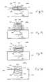
- FIG. 7 a though 7 dare schematic cross-sectional representations of embodiments of a material processing apparatus 300 a-d according to the present invention.
- the material processing apparatus 300 a-dincludes an inductively-coupled toroidal plasma source 302 a-d , as described herein, and a process chamber 304 a-d for processing substrates 306 a-d.
- the inductively-coupled toroidal plasma source 302 a-dincludes a plasma chamber 308 a-d having a side 309 a-d that is open to the process chamber 304 a-d .
- the plasma chamber 308 a-dcomprises a portion of a top surface of the process chamber 304 a-d .
- the plasma chamber 308 a-dcomprises a removable lid that is a portion of the process chamber 304 a-d.
- the plasma chamber 308 a-dis a metallic plasma chamber, such as the metallic plasma chamber described herein in connection with FIGS. 3 though 5 .
- the metal chambersinclude at least one dielectric spacer that prevents induced current flow from forming in the plasma chamber. Metal chambers are advantageous because some metals are more highly resistant to certain chemicals commonly used in plasma processing. Also, metal chambers have much higher thermal conductivity and can tolerate much higher temperatures compared with dielectric chambers. Therefore, metal chambers can be used to generate much higher power plasmas.
- the plasma chamber 308 a-dmay include imbedded cooling channels, as described herein, for passing a fluid that controls the temperature of the plasma chamber 308 a-d.
- the inductively-coupled toroidal plasma source 302 a-b shown in FIGS. 7 a and 7 bincludes a first 310 a-b and a second high permeability magnetic core 312 a-b that surround the plasma chamber 308 a-b .
- any number of high permeability magnetic corescan be used.
- the magnetic cores 310 a-b , 312 a-bare part of the transformer 12 described in connection with FIG. 1 .
- Each of the magnetic cores 310 a-b , 312 a-binduces a potential inside the chamber that forms a plasma 314 a-b that completes a secondary circuit of the transformer.
- the inductively-coupled toroidal plasma sources 302 c-d shown in FIGS. 7 c and 7 dinclude only one high permeability magnetic core 310 c-d that surrounds the plasma chamber 308 c-d . This can allow for different plasma configurations that may be optimized for other applications. This also allows for flexibility in packaging the source onto or as part of a processing chamber.
- FIGS. 7 dillustrates an inductively-coupled toroidal plasma source 302 d having the high permeability magnetic core 310 d partially located in the processing chamber 304 d . Positioning the magnetic core 310 d in the processing chamber 304 d causes the resulting plasma 314 d to extend further into process chamber 304 d .
- This configurationis useful for providing both reactive neutral species and a plasma 314 d to the substrates being processed.
- This configurationis also useful for providing both reactive neutral species and a plasma 314 d to the process chamber 304 d in order to clean the process chamber 304 d.
- a feed gasflows into an inlet 316 a-d , as described in connection with FIG. 1 .
- each of the first 310 a-b and the second high permeability magnetic cores 312 a-b that surround the plasma chamber 308 a-binduce a potential inside the plasma chamber 304 a-b that forms a plasma 314 a-b which completes a secondary circuit of the transformer 12 .
- FIGS. 7 a and 7 beach of the first 310 a-b and the second high permeability magnetic cores 312 a-b that surround the plasma chamber 308 a-b induce a potential inside the plasma chamber 304 a-b that forms a plasma 314 a-b which completes a secondary circuit of the transformer 12 .
- the high permeability magnetic cores 310 c-d that surround the plasma chamber 308 c-dinduce a potential inside the plasma chamber 304 c-d that forms a plasma 314 c-d which completes a secondary circuit of the transformer 12 .
- the plasma 314 a-d formed in the plasma chamber 308 a-dextends into the process chamber 304 a-d .
- reactive neutral speciesare delivered to substrates 306 a-d being processed within the process chamber 304 a-d .
- reactive neutral speciesare delivered to the process chamber 304 a-d in order to clean the process chamber 304 a-d .
- the material processing apparatus 300 a-dis configured and operated to deliver both reactive neutral species and a plasma to substrates 306 a-d being processed or to the process chamber 304 a-d in order to clean the process chamber 304 a-d.
- Integrating the toroidal plasma source 302 a-d into a surface of the process chamber 304 a-d , such as a removable lid of the process chamber,has numerous advantages.
- One advantageis that the integrated toroidal plasma generator is more efficient and, therefore, has higher process rates or lower input gas usage requirements compared with external toroidal plasma generators.
- the integrated toroidal plasma generatorcan also be operated efficiently at higher pressures compared with the external toroidal plasma generators described herein.
- the integrated toroidal plasma sourcehas higher efficiency because the reactive neutral species generated by the source do not have to travel though an intermediate region in order to reach the interior of the process chamber, where they are used for cleaning the process chamber or for processing substrates. Passing the reactive neutral species though an intermediate region causes some of the reactive neutral species to interact with the surface of the intermediate region and become more stable species due to recombination. The recombination reduces the density of reactive neutral species and, therefore, the efficiency of the source.
- Reducing the input gas flow requirementsis particularly advantageous because it reduces the cost of operating the source. For some applications requiring the use of expensive process gases, such as NF3, reducing the gas flow significantly reduces the cost of operating the source. In addition, reducing the gas flow reduces the abatement requirements when using toxic gases. For example, in sources operating with NF3, atomic fluorine (F) recombines into molecular fluorine (F2) and must be removed by an abatement apparatus. Furthermore, reducing the gas flow reduces the required pumping speed and, therefore reduces the cost of the vacuum system and the associated utilities.
- the integrated toroidal plasma source of the present inventionis that the generator can be designed and configured to deliver a plasma to the process chamber, in addition to delivering a reactive neutral species to the process chamber.
- the integrated sourcecan provide a combination of plasma and reactive species to the process chamber.
- Another advantage of the integrated toroidal plasma generator of the present inventionis that the integrated source is more compact compared with the external toroidal plasma generators. This feature makes the integrated source more suitable for compact processing systems. In addition, the integrated source may be less expensive and, therefore, reduce the overall cost of the processing system.
Landscapes
- Engineering & Computer Science (AREA)
- Chemical & Material Sciences (AREA)
- Physics & Mathematics (AREA)
- Plasma & Fusion (AREA)
- Analytical Chemistry (AREA)
- Health & Medical Sciences (AREA)
- Epidemiology (AREA)
- Public Health (AREA)
- Combustion & Propulsion (AREA)
- Plasma Technology (AREA)
Abstract
Description
Claims (51)
Priority Applications (7)
| Application Number | Priority Date | Filing Date | Title |
|---|---|---|---|
| US09/774,165US6924455B1 (en) | 1997-06-26 | 2001-01-26 | Integrated plasma chamber and inductively-coupled toroidal plasma source |
| US09/804,650US6815633B1 (en) | 1997-06-26 | 2001-03-12 | Inductively-coupled toroidal plasma source |
| US10/837,912US7166816B1 (en) | 1997-06-26 | 2004-05-03 | Inductively-coupled torodial plasma source |
| US11/269,917US7569790B2 (en) | 1997-06-26 | 2005-11-08 | Method and apparatus for processing metal bearing gases |
| US11/636,891US7541558B2 (en) | 1997-06-26 | 2006-12-11 | Inductively-coupled toroidal plasma source |
| US12/511,785US8124906B2 (en) | 1997-06-26 | 2009-07-29 | Method and apparatus for processing metal bearing gases |
| US13/336,616US8779322B2 (en) | 1997-06-26 | 2011-12-23 | Method and apparatus for processing metal bearing gases |
Applications Claiming Priority (3)
| Application Number | Priority Date | Filing Date | Title |
|---|---|---|---|
| US08/883,281US6150628A (en) | 1997-06-26 | 1997-06-26 | Toroidal low-field reactive gas source |
| US09/659,881US6486431B1 (en) | 1997-06-26 | 2000-09-12 | Toroidal low-field reactive gas source |
| US09/774,165US6924455B1 (en) | 1997-06-26 | 2001-01-26 | Integrated plasma chamber and inductively-coupled toroidal plasma source |
Related Parent Applications (1)
| Application Number | Title | Priority Date | Filing Date |
|---|---|---|---|
| US09/659,881Continuation-In-PartUS6486431B1 (en) | 1997-06-26 | 2000-09-12 | Toroidal low-field reactive gas source |
Related Child Applications (1)
| Application Number | Title | Priority Date | Filing Date |
|---|---|---|---|
| US09/804,650Continuation-In-PartUS6815633B1 (en) | 1997-06-26 | 2001-03-12 | Inductively-coupled toroidal plasma source |
Publications (1)
| Publication Number | Publication Date |
|---|---|
| US6924455B1true US6924455B1 (en) | 2005-08-02 |
Family
ID=27097917
Family Applications (1)
| Application Number | Title | Priority Date | Filing Date |
|---|---|---|---|
| US09/774,165Expired - LifetimeUS6924455B1 (en) | 1997-06-26 | 2001-01-26 | Integrated plasma chamber and inductively-coupled toroidal plasma source |
Country Status (1)
| Country | Link |
|---|---|
| US (1) | US6924455B1 (en) |
Cited By (48)
| Publication number | Priority date | Publication date | Assignee | Title |
|---|---|---|---|---|
| US20050115924A1 (en)* | 2003-12-01 | 2005-06-02 | Justin Sato | Integration function of RF signal to analyze steady state and non-steady state ( initializaion) of plasmas |
| US20060021968A1 (en)* | 2003-09-26 | 2006-02-02 | Walton Scott G | Time continuous ion-ion plasma |
| US20070103092A1 (en)* | 2005-11-07 | 2007-05-10 | Alan Millner | Method and apparatus of providing power to ignite and sustain a plasma in a reactive gas generator |
| US20100194281A1 (en)* | 2009-02-02 | 2010-08-05 | Advanced Energy Industries, Inc. | Passive Power Distribution for Multiple Electrode Inductive Plasma Source |
| WO2010098779A1 (en)* | 2009-02-27 | 2010-09-02 | Mks Instruments, Inc. | Method and apparatus of providing power to ignite and sustain a plasma in a reactive gas generator |
| WO2011024174A1 (en) | 2009-08-27 | 2011-03-03 | Mosaic Crystals Ltd. | Penetrating plasma generating apparatus for high vacuum chambers |
| US20110095689A1 (en)* | 2009-10-27 | 2011-04-28 | Tyco Healthcare Group Lp | Inductively-Coupled Plasma Device |
| US20110114601A1 (en)* | 2009-11-18 | 2011-05-19 | Applied Materials, Inc. | Plasma source design |
| US20110115378A1 (en)* | 2009-11-18 | 2011-05-19 | Applied Materials, Inc. | Plasma source design |
| US20110132874A1 (en)* | 2009-12-03 | 2011-06-09 | Richard Gottscho | Small plasma chamber systems and methods |
| US20110212624A1 (en)* | 2010-02-26 | 2011-09-01 | Hudson Eric A | System, method and apparatus for plasma etch having independent control of ion generation and dissociation of process gas |
| US8575843B2 (en) | 2008-05-30 | 2013-11-05 | Colorado State University Research Foundation | System, method and apparatus for generating plasma |
| CN103997311A (en)* | 2014-06-09 | 2014-08-20 | 西安电子科技大学 | 3-D full integration EMI filter based on planar coupling inductor |
| US8872525B2 (en) | 2011-11-21 | 2014-10-28 | Lam Research Corporation | System, method and apparatus for detecting DC bias in a plasma processing chamber |
| US8898889B2 (en) | 2011-11-22 | 2014-12-02 | Lam Research Corporation | Chuck assembly for plasma processing |
| US8994270B2 (en) | 2008-05-30 | 2015-03-31 | Colorado State University Research Foundation | System and methods for plasma application |
| US8999104B2 (en) | 2010-08-06 | 2015-04-07 | Lam Research Corporation | Systems, methods and apparatus for separate plasma source control |
| US9028656B2 (en) | 2008-05-30 | 2015-05-12 | Colorado State University Research Foundation | Liquid-gas interface plasma device |
| US9083182B2 (en) | 2011-11-21 | 2015-07-14 | Lam Research Corporation | Bypass capacitors for high voltage bias power in the mid frequency RF range |
| US9155181B2 (en) | 2010-08-06 | 2015-10-06 | Lam Research Corporation | Distributed multi-zone plasma source systems, methods and apparatus |
| US9177762B2 (en) | 2011-11-16 | 2015-11-03 | Lam Research Corporation | System, method and apparatus of a wedge-shaped parallel plate plasma reactor for substrate processing |
| US9263240B2 (en) | 2011-11-22 | 2016-02-16 | Lam Research Corporation | Dual zone temperature control of upper electrodes |
| US9272359B2 (en) | 2008-05-30 | 2016-03-01 | Colorado State University Research Foundation | Liquid-gas interface plasma device |
| US9288886B2 (en) | 2008-05-30 | 2016-03-15 | Colorado State University Research Foundation | Plasma-based chemical source device and method of use thereof |
| US20160157331A1 (en)* | 2014-06-14 | 2016-06-02 | Plusware Corporation | Plasma generating apparatus and on-liquid melting method |
| US9396908B2 (en) | 2011-11-22 | 2016-07-19 | Lam Research Corporation | Systems and methods for controlling a plasma edge region |
| US9449793B2 (en) | 2010-08-06 | 2016-09-20 | Lam Research Corporation | Systems, methods and apparatus for choked flow element extraction |
| US9508530B2 (en) | 2011-11-21 | 2016-11-29 | Lam Research Corporation | Plasma processing chamber with flexible symmetric RF return strap |
| US9532826B2 (en) | 2013-03-06 | 2017-01-03 | Covidien Lp | System and method for sinus surgery |
| US9555145B2 (en) | 2013-03-13 | 2017-01-31 | Covidien Lp | System and method for biofilm remediation |
| US20170062183A1 (en)* | 2015-08-28 | 2017-03-02 | Daihen Corporation | Plasma generation apparatus |
| US9630142B2 (en) | 2013-03-14 | 2017-04-25 | Mks Instruments, Inc. | Toroidal plasma abatement apparatus and method |
| US9909215B2 (en) | 2013-03-15 | 2018-03-06 | Plasmability, Llc | Method of CVD plasma processing with a toroidal plasma processing apparatus |
| US9967965B2 (en) | 2010-08-06 | 2018-05-08 | Lam Research Corporation | Distributed, concentric multi-zone plasma source systems, methods and apparatus |
| US10264663B1 (en) | 2017-10-18 | 2019-04-16 | Lam Research Corporation | Matchless plasma source for semiconductor wafer fabrication |
| US10283325B2 (en) | 2012-10-10 | 2019-05-07 | Lam Research Corporation | Distributed multi-zone plasma source systems, methods and apparatus |
| US10443150B2 (en) | 2015-05-21 | 2019-10-15 | Plasmability, Llc | Toroidal plasma processing apparatus with a shaped workpiece holder |
| US10586686B2 (en) | 2011-11-22 | 2020-03-10 | Law Research Corporation | Peripheral RF feed and symmetric RF return for symmetric RF delivery |
| US11437221B2 (en) | 2017-11-17 | 2022-09-06 | Advanced Energy Industries, Inc. | Spatial monitoring and control of plasma processing environments |
| US11615943B2 (en) | 2017-07-07 | 2023-03-28 | Advanced Energy Industries, Inc. | Inter-period control for passive power distribution of multiple electrode inductive plasma source |
| US11651939B2 (en) | 2017-07-07 | 2023-05-16 | Advanced Energy Industries, Inc. | Inter-period control system for plasma power delivery system and method of operating same |
| US11670487B1 (en) | 2022-01-26 | 2023-06-06 | Advanced Energy Industries, Inc. | Bias supply control and data processing |
| US11842884B2 (en) | 2017-11-17 | 2023-12-12 | Advanced Energy Industries, Inc. | Spatial monitoring and control of plasma processing environments |
| US11942309B2 (en) | 2022-01-26 | 2024-03-26 | Advanced Energy Industries, Inc. | Bias supply with resonant switching |
| US11978613B2 (en) | 2022-09-01 | 2024-05-07 | Advanced Energy Industries, Inc. | Transition control in a bias supply |
| US12046448B2 (en) | 2022-01-26 | 2024-07-23 | Advanced Energy Industries, Inc. | Active switch on time control for bias supply |
| US12142452B2 (en) | 2012-08-28 | 2024-11-12 | Advanced Energy Industries, Inc. | Systems and methods for monitoring faults, anomalies, and other characteristics of a switched mode ion energy distribution system |
| US12230476B2 (en) | 2017-11-17 | 2025-02-18 | Advanced Energy Industries, Inc. | Integrated control of a plasma processing system |
Citations (106)
| Publication number | Priority date | Publication date | Assignee | Title |
|---|---|---|---|---|
| US2981902A (en) | 1958-06-26 | 1961-04-25 | Telecomm Radlioelectriques Et | Automatic impedance matching device |
| US3054742A (en) | 1956-10-26 | 1962-09-18 | Atomic Energy Authority Uk | Gas discharge apparatus |
| US3109801A (en) | 1957-06-20 | 1963-11-05 | Atomic Energy Authority Uk | Gas discharge apparatus |
| US3278384A (en) | 1965-04-13 | 1966-10-11 | Lenard Andrew | Negative "v" stellarator |
| US3343022A (en) | 1965-03-16 | 1967-09-19 | Lockheed Aircraft Corp | Transpiration cooled induction plasma generator |
| US3433705A (en) | 1968-02-28 | 1969-03-18 | Atomic Energy Commission | Stellarator having multipole magnets |
| US3500118A (en) | 1967-07-17 | 1970-03-10 | Gen Electric | Electrodeless gaseous electric discharge devices utilizing ferrite cores |
| US3509500A (en) | 1966-12-05 | 1970-04-28 | Avco Corp | Automatic digital tuning apparatus |
| US3663361A (en) | 1970-02-17 | 1972-05-16 | Atomic Energy Commission | Nuclear fusion device of the air-core tokamak type |
| US3794941A (en) | 1972-05-08 | 1974-02-26 | Hughes Aircraft Co | Automatic antenna impedance tuner including digital control circuits |
| US3906405A (en) | 1974-07-01 | 1975-09-16 | Motorola Inc | Tunable antenna coupling circuit |
| US3987334A (en) | 1975-01-20 | 1976-10-19 | General Electric Company | Integrally ballasted electrodeless fluorescent lamp |
| US4057462A (en) | 1975-02-26 | 1977-11-08 | The United States Of America As Represented By The United States Energy Research And Development Administration | Radio frequency sustained ion energy |
| US4073680A (en) | 1975-06-26 | 1978-02-14 | The United States Of America As Represented By The United States Department Of Energy | Toroidal band limiter for a plasma containment device |
| US4088926A (en) | 1976-05-10 | 1978-05-09 | Nasa | Plasma cleaning device |
| US4095198A (en) | 1977-01-31 | 1978-06-13 | Gte Sylvania Incorporated | Impedance-matching network |
| US4110595A (en) | 1975-06-19 | 1978-08-29 | The United States Of America As Represented By The United States Department Of Energy | High-frequency plasma-heating apparatus |
| US4180763A (en) | 1978-01-25 | 1979-12-25 | General Electric Company | High intensity discharge lamp geometries |
| US4201960A (en) | 1978-05-24 | 1980-05-06 | Motorola, Inc. | Method for automatically matching a radio frequency transmitter to an antenna |
| US4252609A (en) | 1978-11-24 | 1981-02-24 | The United States Of America As Represented By The United States Department Of Energy | Crossed-field divertor for a plasma device |
| US4263096A (en) | 1976-02-02 | 1981-04-21 | The United States Of America As Represented By The United States Department Of Energy | Toroidal magnet system |
| US4282267A (en) | 1979-09-20 | 1981-08-04 | Western Electric Co., Inc. | Methods and apparatus for generating plasmas |
| US4292125A (en) | 1978-08-21 | 1981-09-29 | Massachusetts Institute Of Technology | System and method for generating steady state confining current for a toroidal plasma fusion reactor |
| US4368092A (en) | 1981-04-02 | 1983-01-11 | The Perkin-Elmer Corporation | Apparatus for the etching for semiconductor devices |
| US4431898A (en) | 1981-09-01 | 1984-02-14 | The Perkin-Elmer Corporation | Inductively coupled discharge for plasma etching and resist stripping |
| US4431901A (en) | 1982-07-02 | 1984-02-14 | The United States Of America As Represented By The United States Department Of Energy | Induction plasma tube |
| US4486723A (en) | 1983-01-06 | 1984-12-04 | Rca Corporation | Diode switching system for a selectable impedance matching network |
| US4486722A (en) | 1982-02-18 | 1984-12-04 | Rockwell International Corporation | Pin diode switched impedance matching network having diode driver circuits transparent to RF potential |
| JPS611024Y2 (en) | 1981-10-09 | 1986-01-14 | ||
| US4601871A (en) | 1983-05-17 | 1986-07-22 | The United States Of America As Represented By The United States Department Of Energy | Steady state compact toroidal plasma production |
| US4626400A (en) | 1983-06-01 | 1986-12-02 | The United States Of America As Represented By The United States Department Of Energy | Variable control of neutron albedo in toroidal fusion devices |
| USH268H (en) | 1984-03-20 | 1987-05-05 | The United States Of America As Represented By The United States Department Of Energy | Elmo bumpy square plasma confinement device |
| US4679007A (en) | 1985-05-20 | 1987-07-07 | Advanced Energy, Inc. | Matching circuit for delivering radio frequency electromagnetic energy to a variable impedance load |
| US4689192A (en) | 1983-08-30 | 1987-08-25 | Mitsubishi Denki Kabushiki Kaisha | Nuclear fusion reactor |
| US4732761A (en) | 1985-03-23 | 1988-03-22 | Nippon Telegraph And Telephone Corporation | Thin film forming apparatus and method |
| US4735765A (en) | 1985-11-26 | 1988-04-05 | The United States Of America As Represented By The United States Department Of Energy | Flexible helical-axis stellarator |
| US4748383A (en) | 1985-11-04 | 1988-05-31 | U. S. Philips Corporation | DC-AC converter for igniting and supplying a discharge lamp |
| US4767590A (en) | 1986-04-25 | 1988-08-30 | The United States Of America As Represented By The United States Department Of Energy | Anomalous - viscosity current drive |
| US4780803A (en) | 1986-10-02 | 1988-10-25 | G. H. Industrial S.A. | High frequency generator to be used in induction heating, laser, plasma and the alike |
| US4786352A (en) | 1986-09-12 | 1988-11-22 | Benzing Technologies, Inc. | Apparatus for in-situ chamber cleaning |
| USH554H (en) | 1972-03-02 | 1988-12-06 | The United States Of America As Represented By The United States Department Of Energy | Toroidal reactor |
| US4794217A (en) | 1985-04-01 | 1988-12-27 | Qing Hua University | Induction system for rapid heat treatment of semiconductor wafers |
| US4859399A (en) | 1977-10-13 | 1989-08-22 | Fdx Patents Holding Company, N.V. | Modular fusion power apparatus using disposable core |
| US4861622A (en) | 1985-09-21 | 1989-08-29 | Semiconductor Energy Laboratory Co., Ltd. | Method for forming a film coat on the inside of a depression |
| US4863671A (en) | 1986-06-02 | 1989-09-05 | Hitachi, Ltd. | Plasma confinement system |
| US4877757A (en) | 1987-07-16 | 1989-10-31 | Texas Instruments Incorporated | Method of sequential cleaning and passivating a GaAs substrate using remote oxygen plasma |
| US4878149A (en) | 1986-02-06 | 1989-10-31 | Sorbios Verfahrenstechnische Gerate Und Gmbh | Device for generating ions in gas streams |
| US4908492A (en) | 1988-05-11 | 1990-03-13 | Hitachi, Ltd. | Microwave plasma production apparatus |
| US4918031A (en) | 1988-12-28 | 1990-04-17 | American Telephone And Telegraph Company,At&T Bell Laboratories | Processes depending on plasma generation using a helical resonator |
| WO1990010945A1 (en) | 1989-03-06 | 1990-09-20 | Nordiko Limited | Ion gun |
| JPH02260399A (en) | 1989-03-31 | 1990-10-23 | Fuji Denpa Koki Kk | Generating method of high pressure plasma arc |
| US4985113A (en) | 1989-03-10 | 1991-01-15 | Hitachi, Ltd. | Sample treating method and apparatus |
| US4996077A (en) | 1988-10-07 | 1991-02-26 | Texas Instruments Incorporated | Distributed ECR remote plasma processing and apparatus |
| US5030889A (en) | 1989-12-21 | 1991-07-09 | General Electric Company | Lamp ballast configuration |
| US5061838A (en) | 1989-06-23 | 1991-10-29 | Massachusetts Institute Of Technology | Toroidal electron cyclotron resonance reactor |
| US5130003A (en) | 1990-06-14 | 1992-07-14 | Conrad Richard H | method of powering corona discharge in ozone generators |
| US5153484A (en) | 1991-10-31 | 1992-10-06 | General Electric Company | Electrodeless high intensity discharge lamp excitation coil and ballast configuration for maximum efficiency |
| US5187454A (en) | 1992-01-23 | 1993-02-16 | Applied Materials, Inc. | Electronically tuned matching network using predictor-corrector control system |
| US5200595A (en) | 1991-04-12 | 1993-04-06 | Universite De Sherbrooke | High performance induction plasma torch with a water-cooled ceramic confinement tube |
| JPH05166595A (en) | 1991-12-12 | 1993-07-02 | Fuji Denpa Koki Kk | Method for generating plasma of high atmospheric pressure and high density |
| US5254830A (en) | 1991-05-07 | 1993-10-19 | Hughes Aircraft Company | System for removing material from semiconductor wafers using a contained plasma |
| US5277751A (en) | 1992-06-18 | 1994-01-11 | Ogle John S | Method and apparatus for producing low pressure planar plasma using a coil with its axis parallel to the surface of a coupling window |
| US5290382A (en) | 1991-12-13 | 1994-03-01 | Hughes Aircraft Company | Methods and apparatus for generating a plasma for "downstream" rapid shaping of surfaces of substrates and films |
| US5303139A (en) | 1991-07-31 | 1994-04-12 | Magtron Magneto Elektronische Gerate Gmbh | Low frequency, pulsed, bipolar power supply for a plasma chamber |
| US5336355A (en) | 1991-12-13 | 1994-08-09 | Hughes Aircraft Company | Methods and apparatus for confinement of a plasma etch region for precision shaping of surfaces of substances and films |
| US5346578A (en) | 1992-11-04 | 1994-09-13 | Novellus Systems, Inc. | Induction plasma source |
| US5364600A (en) | 1990-11-02 | 1994-11-15 | Sorbios Gmbh | Apparatus for producing ozone from oxygen |
| RU2022917C1 (en) | 1989-09-27 | 1994-11-15 | Уланов Игорь Максимович | Process of preparing nitrogen oxide |
| US5401350A (en) | 1993-03-08 | 1995-03-28 | Lsi Logic Corporation | Coil configurations for improved uniformity in inductively coupled plasma systems |
| US5406177A (en) | 1994-04-18 | 1995-04-11 | General Electric Company | Gas discharge lamp ballast circuit with compact starting circuit |
| US5414238A (en) | 1992-10-02 | 1995-05-09 | Martin Marietta Corporation | Resonant power supply for an arcjet thruster |
| US5430355A (en) | 1993-07-30 | 1995-07-04 | Texas Instruments Incorporated | RF induction plasma source for plasma processing |
| US5440206A (en) | 1992-06-26 | 1995-08-08 | Tokyo Electron Ltd. | Plasma processing apparatus comprising means for generating rotating magnetic field |
| US5458732A (en) | 1992-04-14 | 1995-10-17 | Texas Instruments Incorporated | Method and system for identifying process conditions |
| US5460689A (en) | 1994-02-28 | 1995-10-24 | Applied Materials, Inc. | High pressure plasma treatment method and apparatus |
| US5468296A (en) | 1993-12-17 | 1995-11-21 | Lsi Logic Corporation | Apparatus for igniting low pressure inductively coupled plasma |
| US5472561A (en) | 1993-12-07 | 1995-12-05 | Sematech, Inc. | Radio frequency monitor for semiconductor process control |
| US5474648A (en) | 1994-07-29 | 1995-12-12 | Lsi Logic Corporation | Uniform and repeatable plasma processing |
| US5479072A (en) | 1991-11-12 | 1995-12-26 | General Electric Company | Low mercury arc discharge lamp containing neodymium |
| SU957744A1 (en) | 1980-06-09 | 1996-02-10 | Всесоюзный научно-исследовательский, проектно-конструкторский и технологический институт токов высокой частоты им.В.П.Вологдина | Transformer plasma generator |
| RU2056702C1 (en) | 1990-07-09 | 1996-03-20 | Уланов Игорь Максимович | Transformer-type plasmatron |
| US5506507A (en) | 1992-09-18 | 1996-04-09 | Sorbios Verfahrenstechnische Gerate Und Systeme Gmbh | Apparatus for measuring ions in a clean room gas flow using a spherical electrode |
| US5505780A (en) | 1992-03-18 | 1996-04-09 | International Business Machines Corporation | High-density plasma-processing tool with toroidal magnetic field |
| DE3942560C2 (en) | 1989-12-22 | 1996-05-02 | Dressler Hochfrequenztechnik G | High frequency generator for a plasma generating consumer |
| US5514246A (en) | 1994-06-02 | 1996-05-07 | Micron Technology, Inc. | Plasma reactors and method of cleaning a plasma reactor |
| US5556549A (en) | 1994-05-02 | 1996-09-17 | Lsi Logic Corporation | Power control and delivery in plasma processing equipment |
| US5565247A (en) | 1991-08-30 | 1996-10-15 | Canon Kabushiki Kaisha | Process for forming a functional deposited film |
| US5573595A (en) | 1995-09-29 | 1996-11-12 | Lam Research Corporation | Methods and apparatus for generating plasma |
| US5576629A (en) | 1994-10-24 | 1996-11-19 | Fourth State Technology, Inc. | Plasma monitoring and control method and system |
| US5618382A (en) | 1989-10-03 | 1997-04-08 | Applied Materials, Inc. | High-frequency semiconductor wafer processing apparatus and method |
| US5630880A (en) | 1996-03-07 | 1997-05-20 | Eastlund; Bernard J. | Method and apparatus for a large volume plasma processor that can utilize any feedstock material |
| US5643364A (en) | 1994-11-30 | 1997-07-01 | Applied Materials, Inc. | Plasma chamber with fixed RF matching |
| US5654679A (en) | 1996-06-13 | 1997-08-05 | Rf Power Products, Inc. | Apparatus for matching a variable load impedance with an RF power generator impedance |
| US5670881A (en) | 1996-02-09 | 1997-09-23 | Toshiba America, Inc. | Discrete step remotely adjustable matching circuit for MRI RF coils |
| RU2094961C1 (en) | 1989-07-20 | 1997-10-27 | Уланов Игорь Максимович | Transformer-type plasmatron |
| US5712592A (en) | 1995-03-06 | 1998-01-27 | Applied Materials, Inc. | RF plasma power supply combining technique for increased stability |
| US5747935A (en) | 1992-04-16 | 1998-05-05 | Advanced Energy Industries, Inc. | Method and apparatus for stabilizing switch-mode powered RF plasma processing |
| US5756400A (en) | 1995-12-08 | 1998-05-26 | Applied Materials, Inc. | Method and apparatus for cleaning by-products from plasma chamber surfaces |
| US5773919A (en) | 1986-10-02 | 1998-06-30 | Electron Power Systems | Electron spiral toroid |
| US5811022A (en) | 1994-11-15 | 1998-09-22 | Mattson Technology, Inc. | Inductive plasma reactor |
| US5998933A (en) | 1998-04-06 | 1999-12-07 | Shun'ko; Evgeny V. | RF plasma inductor with closed ferrite core |
| US6007879A (en) | 1995-04-07 | 1999-12-28 | Advanced Energy Industries, Inc. | Adjustable energy quantum thin film plasma processing system |
| US6164241A (en) | 1998-06-30 | 2000-12-26 | Lam Research Corporation | Multiple coil antenna for inductively-coupled plasma generation systems |
| US6253704B1 (en) | 1995-10-13 | 2001-07-03 | Mattson Technology, Inc. | Apparatus and method for pulsed plasma processing of a semiconductor substrate |
| US6424232B1 (en) | 1999-11-30 | 2002-07-23 | Advanced Energy's Voorhees Operations | Method and apparatus for matching a variable load impedance with an RF power generator impedance |
| US6459066B1 (en) | 2000-08-25 | 2002-10-01 | Board Of Regents, The University Of Texas System | Transmission line based inductively coupled plasma source with stable impedance |
- 2001
- 2001-01-26USUS09/774,165patent/US6924455B1/ennot_activeExpired - Lifetime
Patent Citations (108)
| Publication number | Priority date | Publication date | Assignee | Title |
|---|---|---|---|---|
| US3054742A (en) | 1956-10-26 | 1962-09-18 | Atomic Energy Authority Uk | Gas discharge apparatus |
| US3109801A (en) | 1957-06-20 | 1963-11-05 | Atomic Energy Authority Uk | Gas discharge apparatus |
| US2981902A (en) | 1958-06-26 | 1961-04-25 | Telecomm Radlioelectriques Et | Automatic impedance matching device |
| US3343022A (en) | 1965-03-16 | 1967-09-19 | Lockheed Aircraft Corp | Transpiration cooled induction plasma generator |
| US3278384A (en) | 1965-04-13 | 1966-10-11 | Lenard Andrew | Negative "v" stellarator |
| US3509500A (en) | 1966-12-05 | 1970-04-28 | Avco Corp | Automatic digital tuning apparatus |
| US3500118A (en) | 1967-07-17 | 1970-03-10 | Gen Electric | Electrodeless gaseous electric discharge devices utilizing ferrite cores |
| US3433705A (en) | 1968-02-28 | 1969-03-18 | Atomic Energy Commission | Stellarator having multipole magnets |
| US3663361A (en) | 1970-02-17 | 1972-05-16 | Atomic Energy Commission | Nuclear fusion device of the air-core tokamak type |
| USH554H (en) | 1972-03-02 | 1988-12-06 | The United States Of America As Represented By The United States Department Of Energy | Toroidal reactor |
| US3794941A (en) | 1972-05-08 | 1974-02-26 | Hughes Aircraft Co | Automatic antenna impedance tuner including digital control circuits |
| US3906405A (en) | 1974-07-01 | 1975-09-16 | Motorola Inc | Tunable antenna coupling circuit |
| US3987334A (en) | 1975-01-20 | 1976-10-19 | General Electric Company | Integrally ballasted electrodeless fluorescent lamp |
| US4057462A (en) | 1975-02-26 | 1977-11-08 | The United States Of America As Represented By The United States Energy Research And Development Administration | Radio frequency sustained ion energy |
| US4110595A (en) | 1975-06-19 | 1978-08-29 | The United States Of America As Represented By The United States Department Of Energy | High-frequency plasma-heating apparatus |
| US4073680A (en) | 1975-06-26 | 1978-02-14 | The United States Of America As Represented By The United States Department Of Energy | Toroidal band limiter for a plasma containment device |
| US4263096A (en) | 1976-02-02 | 1981-04-21 | The United States Of America As Represented By The United States Department Of Energy | Toroidal magnet system |
| US4088926A (en) | 1976-05-10 | 1978-05-09 | Nasa | Plasma cleaning device |
| US4095198A (en) | 1977-01-31 | 1978-06-13 | Gte Sylvania Incorporated | Impedance-matching network |
| US4859399A (en) | 1977-10-13 | 1989-08-22 | Fdx Patents Holding Company, N.V. | Modular fusion power apparatus using disposable core |
| US4180763A (en) | 1978-01-25 | 1979-12-25 | General Electric Company | High intensity discharge lamp geometries |
| US4201960A (en) | 1978-05-24 | 1980-05-06 | Motorola, Inc. | Method for automatically matching a radio frequency transmitter to an antenna |
| US4292125A (en) | 1978-08-21 | 1981-09-29 | Massachusetts Institute Of Technology | System and method for generating steady state confining current for a toroidal plasma fusion reactor |
| US4252609A (en) | 1978-11-24 | 1981-02-24 | The United States Of America As Represented By The United States Department Of Energy | Crossed-field divertor for a plasma device |
| US4282267A (en) | 1979-09-20 | 1981-08-04 | Western Electric Co., Inc. | Methods and apparatus for generating plasmas |
| SU957744A1 (en) | 1980-06-09 | 1996-02-10 | Всесоюзный научно-исследовательский, проектно-конструкторский и технологический институт токов высокой частоты им.В.П.Вологдина | Transformer plasma generator |
| US4368092A (en) | 1981-04-02 | 1983-01-11 | The Perkin-Elmer Corporation | Apparatus for the etching for semiconductor devices |
| US4431898A (en) | 1981-09-01 | 1984-02-14 | The Perkin-Elmer Corporation | Inductively coupled discharge for plasma etching and resist stripping |
| JPS611024Y2 (en) | 1981-10-09 | 1986-01-14 | ||
| US4486722A (en) | 1982-02-18 | 1984-12-04 | Rockwell International Corporation | Pin diode switched impedance matching network having diode driver circuits transparent to RF potential |
| US4431901A (en) | 1982-07-02 | 1984-02-14 | The United States Of America As Represented By The United States Department Of Energy | Induction plasma tube |
| US4486723A (en) | 1983-01-06 | 1984-12-04 | Rca Corporation | Diode switching system for a selectable impedance matching network |
| US4601871A (en) | 1983-05-17 | 1986-07-22 | The United States Of America As Represented By The United States Department Of Energy | Steady state compact toroidal plasma production |
| US4626400A (en) | 1983-06-01 | 1986-12-02 | The United States Of America As Represented By The United States Department Of Energy | Variable control of neutron albedo in toroidal fusion devices |
| US4689192A (en) | 1983-08-30 | 1987-08-25 | Mitsubishi Denki Kabushiki Kaisha | Nuclear fusion reactor |
| USH268H (en) | 1984-03-20 | 1987-05-05 | The United States Of America As Represented By The United States Department Of Energy | Elmo bumpy square plasma confinement device |
| US4732761A (en) | 1985-03-23 | 1988-03-22 | Nippon Telegraph And Telephone Corporation | Thin film forming apparatus and method |
| US4794217A (en) | 1985-04-01 | 1988-12-27 | Qing Hua University | Induction system for rapid heat treatment of semiconductor wafers |
| US4679007A (en) | 1985-05-20 | 1987-07-07 | Advanced Energy, Inc. | Matching circuit for delivering radio frequency electromagnetic energy to a variable impedance load |
| US4861622A (en) | 1985-09-21 | 1989-08-29 | Semiconductor Energy Laboratory Co., Ltd. | Method for forming a film coat on the inside of a depression |
| US4748383A (en) | 1985-11-04 | 1988-05-31 | U. S. Philips Corporation | DC-AC converter for igniting and supplying a discharge lamp |
| US4735765A (en) | 1985-11-26 | 1988-04-05 | The United States Of America As Represented By The United States Department Of Energy | Flexible helical-axis stellarator |
| US4878149A (en) | 1986-02-06 | 1989-10-31 | Sorbios Verfahrenstechnische Gerate Und Gmbh | Device for generating ions in gas streams |
| US4767590A (en) | 1986-04-25 | 1988-08-30 | The United States Of America As Represented By The United States Department Of Energy | Anomalous - viscosity current drive |
| US4863671A (en) | 1986-06-02 | 1989-09-05 | Hitachi, Ltd. | Plasma confinement system |
| US4786352A (en) | 1986-09-12 | 1988-11-22 | Benzing Technologies, Inc. | Apparatus for in-situ chamber cleaning |
| US4780803A (en) | 1986-10-02 | 1988-10-25 | G. H. Industrial S.A. | High frequency generator to be used in induction heating, laser, plasma and the alike |
| US5773919A (en) | 1986-10-02 | 1998-06-30 | Electron Power Systems | Electron spiral toroid |
| US4877757A (en) | 1987-07-16 | 1989-10-31 | Texas Instruments Incorporated | Method of sequential cleaning and passivating a GaAs substrate using remote oxygen plasma |
| US4908492A (en) | 1988-05-11 | 1990-03-13 | Hitachi, Ltd. | Microwave plasma production apparatus |
| US4996077A (en) | 1988-10-07 | 1991-02-26 | Texas Instruments Incorporated | Distributed ECR remote plasma processing and apparatus |
| US4918031A (en) | 1988-12-28 | 1990-04-17 | American Telephone And Telegraph Company,At&T Bell Laboratories | Processes depending on plasma generation using a helical resonator |
| WO1990010945A1 (en) | 1989-03-06 | 1990-09-20 | Nordiko Limited | Ion gun |
| US4985113A (en) | 1989-03-10 | 1991-01-15 | Hitachi, Ltd. | Sample treating method and apparatus |
| JPH02260399A (en) | 1989-03-31 | 1990-10-23 | Fuji Denpa Koki Kk | Generating method of high pressure plasma arc |
| US5061838A (en) | 1989-06-23 | 1991-10-29 | Massachusetts Institute Of Technology | Toroidal electron cyclotron resonance reactor |
| RU2094961C1 (en) | 1989-07-20 | 1997-10-27 | Уланов Игорь Максимович | Transformer-type plasmatron |
| RU2022917C1 (en) | 1989-09-27 | 1994-11-15 | Уланов Игорь Максимович | Process of preparing nitrogen oxide |
| US5618382A (en) | 1989-10-03 | 1997-04-08 | Applied Materials, Inc. | High-frequency semiconductor wafer processing apparatus and method |
| US5030889A (en) | 1989-12-21 | 1991-07-09 | General Electric Company | Lamp ballast configuration |
| DE3942560C2 (en) | 1989-12-22 | 1996-05-02 | Dressler Hochfrequenztechnik G | High frequency generator for a plasma generating consumer |
| US5130003A (en) | 1990-06-14 | 1992-07-14 | Conrad Richard H | method of powering corona discharge in ozone generators |
| RU2056702C1 (en) | 1990-07-09 | 1996-03-20 | Уланов Игорь Максимович | Transformer-type plasmatron |
| US5364600A (en) | 1990-11-02 | 1994-11-15 | Sorbios Gmbh | Apparatus for producing ozone from oxygen |
| US5200595A (en) | 1991-04-12 | 1993-04-06 | Universite De Sherbrooke | High performance induction plasma torch with a water-cooled ceramic confinement tube |
| US5254830A (en) | 1991-05-07 | 1993-10-19 | Hughes Aircraft Company | System for removing material from semiconductor wafers using a contained plasma |
| US5303139A (en) | 1991-07-31 | 1994-04-12 | Magtron Magneto Elektronische Gerate Gmbh | Low frequency, pulsed, bipolar power supply for a plasma chamber |
| US5565247A (en) | 1991-08-30 | 1996-10-15 | Canon Kabushiki Kaisha | Process for forming a functional deposited film |
| US5153484A (en) | 1991-10-31 | 1992-10-06 | General Electric Company | Electrodeless high intensity discharge lamp excitation coil and ballast configuration for maximum efficiency |
| US5479072A (en) | 1991-11-12 | 1995-12-26 | General Electric Company | Low mercury arc discharge lamp containing neodymium |
| JPH05166595A (en) | 1991-12-12 | 1993-07-02 | Fuji Denpa Koki Kk | Method for generating plasma of high atmospheric pressure and high density |
| US5336355A (en) | 1991-12-13 | 1994-08-09 | Hughes Aircraft Company | Methods and apparatus for confinement of a plasma etch region for precision shaping of surfaces of substances and films |
| US5290382A (en) | 1991-12-13 | 1994-03-01 | Hughes Aircraft Company | Methods and apparatus for generating a plasma for "downstream" rapid shaping of surfaces of substrates and films |
| US5187454A (en) | 1992-01-23 | 1993-02-16 | Applied Materials, Inc. | Electronically tuned matching network using predictor-corrector control system |
| US5505780A (en) | 1992-03-18 | 1996-04-09 | International Business Machines Corporation | High-density plasma-processing tool with toroidal magnetic field |
| US5458732A (en) | 1992-04-14 | 1995-10-17 | Texas Instruments Incorporated | Method and system for identifying process conditions |
| US5747935A (en) | 1992-04-16 | 1998-05-05 | Advanced Energy Industries, Inc. | Method and apparatus for stabilizing switch-mode powered RF plasma processing |
| US5277751A (en) | 1992-06-18 | 1994-01-11 | Ogle John S | Method and apparatus for producing low pressure planar plasma using a coil with its axis parallel to the surface of a coupling window |
| US5440206A (en) | 1992-06-26 | 1995-08-08 | Tokyo Electron Ltd. | Plasma processing apparatus comprising means for generating rotating magnetic field |
| US5506507A (en) | 1992-09-18 | 1996-04-09 | Sorbios Verfahrenstechnische Gerate Und Systeme Gmbh | Apparatus for measuring ions in a clean room gas flow using a spherical electrode |
| US5414238A (en) | 1992-10-02 | 1995-05-09 | Martin Marietta Corporation | Resonant power supply for an arcjet thruster |
| US5346578A (en) | 1992-11-04 | 1994-09-13 | Novellus Systems, Inc. | Induction plasma source |
| US5405480A (en) | 1992-11-04 | 1995-04-11 | Novellus Systems, Inc. | Induction plasma source |
| US5401350A (en) | 1993-03-08 | 1995-03-28 | Lsi Logic Corporation | Coil configurations for improved uniformity in inductively coupled plasma systems |
| US5430355A (en) | 1993-07-30 | 1995-07-04 | Texas Instruments Incorporated | RF induction plasma source for plasma processing |
| US5472561A (en) | 1993-12-07 | 1995-12-05 | Sematech, Inc. | Radio frequency monitor for semiconductor process control |
| US5468296A (en) | 1993-12-17 | 1995-11-21 | Lsi Logic Corporation | Apparatus for igniting low pressure inductively coupled plasma |
| US5460689A (en) | 1994-02-28 | 1995-10-24 | Applied Materials, Inc. | High pressure plasma treatment method and apparatus |
| US5406177A (en) | 1994-04-18 | 1995-04-11 | General Electric Company | Gas discharge lamp ballast circuit with compact starting circuit |
| US5556549A (en) | 1994-05-02 | 1996-09-17 | Lsi Logic Corporation | Power control and delivery in plasma processing equipment |
| US5514246A (en) | 1994-06-02 | 1996-05-07 | Micron Technology, Inc. | Plasma reactors and method of cleaning a plasma reactor |
| US5474648A (en) | 1994-07-29 | 1995-12-12 | Lsi Logic Corporation | Uniform and repeatable plasma processing |
| US5939886A (en) | 1994-10-24 | 1999-08-17 | Advanced Energy Industries, Inc. | Plasma monitoring and control method and system |
| US5576629A (en) | 1994-10-24 | 1996-11-19 | Fourth State Technology, Inc. | Plasma monitoring and control method and system |
| US5811022A (en) | 1994-11-15 | 1998-09-22 | Mattson Technology, Inc. | Inductive plasma reactor |
| US5643364A (en) | 1994-11-30 | 1997-07-01 | Applied Materials, Inc. | Plasma chamber with fixed RF matching |
| US5712592A (en) | 1995-03-06 | 1998-01-27 | Applied Materials, Inc. | RF plasma power supply combining technique for increased stability |
| US6007879A (en) | 1995-04-07 | 1999-12-28 | Advanced Energy Industries, Inc. | Adjustable energy quantum thin film plasma processing system |
| US5573595A (en) | 1995-09-29 | 1996-11-12 | Lam Research Corporation | Methods and apparatus for generating plasma |
| US6253704B1 (en) | 1995-10-13 | 2001-07-03 | Mattson Technology, Inc. | Apparatus and method for pulsed plasma processing of a semiconductor substrate |
| US5756400A (en) | 1995-12-08 | 1998-05-26 | Applied Materials, Inc. | Method and apparatus for cleaning by-products from plasma chamber surfaces |
| US5670881A (en) | 1996-02-09 | 1997-09-23 | Toshiba America, Inc. | Discrete step remotely adjustable matching circuit for MRI RF coils |
| US5630880A (en) | 1996-03-07 | 1997-05-20 | Eastlund; Bernard J. | Method and apparatus for a large volume plasma processor that can utilize any feedstock material |
| US5654679A (en) | 1996-06-13 | 1997-08-05 | Rf Power Products, Inc. | Apparatus for matching a variable load impedance with an RF power generator impedance |
| US5998933A (en) | 1998-04-06 | 1999-12-07 | Shun'ko; Evgeny V. | RF plasma inductor with closed ferrite core |
| US6164241A (en) | 1998-06-30 | 2000-12-26 | Lam Research Corporation | Multiple coil antenna for inductively-coupled plasma generation systems |
| US6424232B1 (en) | 1999-11-30 | 2002-07-23 | Advanced Energy's Voorhees Operations | Method and apparatus for matching a variable load impedance with an RF power generator impedance |
| US6459066B1 (en) | 2000-08-25 | 2002-10-01 | Board Of Regents, The University Of Texas System | Transmission line based inductively coupled plasma source with stable impedance |
Non-Patent Citations (54)
| Title |
|---|
| "An Intelligent Solution to RF Load-Power Variability," vol. 2, No. 3, 3<SUP>rd </SUP>Quarter (1995) pp. 1-8. |
| "International Lighting Review, Induction Lighting," The Global Lighting Magazine, Apr. 1996. |
| "Linear Circuit Analysis," Electrical Engineering Handbook, (Copyright 1993) pp. 85. |
| "Principals and Techniques," Electrical Engineers' Handbook, (Copyright 1997) pp. 3.40-3.41. |
| "The Advanced Energy PE 2500 W, 100 kHz Generator with Load Matching User Manual," Sep. 1989. |
| "An Intelligent Solution to RF Load-Power Variability," vol. 2, No. 3, 3rd Quarter (1995) pp. 1-8. |
| Advanced Energy Industries, Inc., Presentation "Advances in 13.56 MHz Applications" by Knipp (date unknown) pp. 1-32. |
| Advanced Energy Marketing Materials, "Impedance Matching," (Copyright 1992) pp. 1-8. |
| Advanced Energy Marketing Materials, "Introducing Power Supplies and Plasma Systems," (Copyright 1992) pp. 1-8. |
| Amended Complain and Jury Demand, filed in the United States District Court for the District of Colorado, by Advanced Energy Industries, Inc., dated Dec. 15, 2003. |
| Answer, filed in the United States District Court for the District of Delaware, by Advanced Energy Industries, Inc., dated Dec. 10, 2003. |
| Benesch, Breakdown in the Pretext Tokamak, "Chapter Two-The Machine," Jun. 1981, pp. 15-16. |
| Cayless et al., "Lamps and Lighting," Third Edition, pp. 280-286. |
| Complaint for Declaratory Judgment of Non-Infringement, filed in the United States District Court for the District of Colorado, by Advanced Energy Industries, Inc., dated Apr. 3, 2003. |
| Complaint, filed in the United States District Court for the District of Delaware, by MKS Instruments, Inc. and Applied Science and Technology, Inc., dated May 14, 2003. |
| CRC Handbook of Chemistry and Physics (1979-1980) pp. E-60. |
| E. Kandler et al., "Characterization of Plasma in an Inductively Coupled High-Dense Plasma Source" Surface Coartings & Tech. 74 75:539-545 (1995). |
| Eckert, "The Hundred Year History of Induction Discharges," Proceedings of The Second Annual International Conference of Plasma Chemistry and Technology (Nov. 12-13, 1984) pp 171-202. |
| F. Maier, "Electronic Circuits for the Generation and Transfer of High-Power Pulses in Nuclear Fusion Installations" IEEE Transactions on Plasma Science PS-12(3): 191-198 (1984). |
| Foutz, "Switching-Mode Power Supply Design" (Jan. 17, 2001) pp. 1-3. |
| G. Soucy et al., "Parametric Study of the Decomposition of NH<SUB>3 </SUB>for an Induction Plasma Reactor Design" Plasma Chem. and Plasma Proc. 15(4):693-710 (1995). |
| G. Soucy et al., "Parametric Study of the Decomposition of NH3 for an Induction Plasma Reactor Design" Plasma Chem. and Plasma Proc. 15(4):693-710 (1995). |
| Gale et al., "Characterization of a Micromachined Electrical Field-Flow Fractionation (muEFFF) System" (no date) pp. 1-6. |
| Gale et al., "Characterization of a Micromachined Electrical Field-Flow Fractionation (μEFFF) System" (no date) pp. 1-6. |
| H.U. Eckert, "An Electrodeless Discharge at 60 Hz" IEEE Trans. on Plasma Sci. PS-2:308-309 (1974). |
| H.U. Eckert, "Analysis of Thermal Induction Plasmas between Coaxial Cylinders" J. Appl. Phys.43(1):46-52 (1972). |
| H.U. Eckert, "Induction Plasmas at Low Frequencies" AIAA Journal 9(8):1452-1456 (1971). |
| H.U. Eckert, "The Induction Arc: A State-of-the-Art Review" High Temp. Sci. 6:99-134 (1974). |
| Heckman et al., Advanced Energy Marketing Materials, "The Evolution of RF Power Delivery in Plasma Processing," (Copyright 1998) pp. 1-8. |
| Hiramatsu et al., "Generation of Strongly Ionized Aluminum Plasma in a Low-Temperature Tokamak Discharge," Japanese Journal of Applied Physics, vol. 31 (Jul. 1992) pp. 2243-2248. |
| Hirose et al., "STOR II A Tokamak for Plasma Heating Studies," Plasma Physics Laboratory, University of Saskatchewan, Apr. 1981, pp. 11-14. |
| International Search Report dated Nov. 5, 1998 in corresponding PCT Application No. PCT/US98/13155. |
| Kassakian et al., Principles of Power Electronics, 1991, Chapter 1, pp. 1-8. |
| Kogan et al., "Research into Potential for Creating Transformer Type Plasmatrons," Teplofizika Vysokikh Temperatur, vol. 31, No. 1, 1993, pp. 1-8. |
| Lenk, "Switching Power-Supply Basics," Simplified Design of Switching Power Supplies (1995) pp. 1. |
| Lieberman et al., Principles of Plasma Discharges and Material Processing; Chapter 12 "Inductive Discharges," pp. 387-389. |
| Massey, "Fabric antennas for mobile telephony integrated within clothing" (no date) pp. 1-4. |
| Memorandum Opinion, US District Court for the District of Delaware dated Feb. 12, 2004. |
| Order, US District Court for the District of Delaware dated Feb. 12, 2004. |
| Osram ECG-SPOT Brochure, Feb. 1997, pp. 1-12. |
| Osram Endura 150W Product Information Brochure, Nov. 1996, pp. 1-4. |
| Pressman, Switching Power Supply Design, (no date) pp. xvii. |
| R.A. Krakowski et al., "Prospects for Using Low-Frequency Induction Plasmas for Bulk-Chemical Processing: A Systems Analysis" First INEL Workshop on Plasma Applications to Waste Treatment, Idaho Fall, Idaho, Jan. 16-17, 1991. |
| Remote Plasma Source Chapter 2, (Mar. 2001) pp. 2-1-2-6. |
| S.V. Dresvin, Physics & Tech. of Low Temp. Plasmas, H. Eckert ed, p. 234 (1977). |
| T.B. Reed, "Growth of Refractory Crystals Using the Induction Plasma Torch" J. Appl. Phys. 32(12)2534-2535 (1961). |
| T.B. Reed, "Heat-Transfer Intensity from Induction Plasma Flames and Oxy-Hydrogen Flames" J. Appl. Phys. 34(8)2266-2269 (1963). |
| T.B. Reed, "High-Power Low-Density Induction Plasmas" Communications 3146-3147 (1963). |
| T.B. Reed, "Induction-Coupled Plasma Torch" J. Appl. Phys. 32(5):821-824 (1961). |
| Talanov et al., "Measurement of the absolute penetration depth and surface resistance of superconductors and normal metals with the variable parallel plate resonator," Review of Scientific Instruments, vol. 71, No. 5 (May 2000) pp. 2136-2146. |
| Ulanov et al., "Study of the Transformer-Coupled Induction Toroidal Discharge for Development of Plasma-Chemical Reactors and New Light Sources," (date unknown) pp. 1-19. |
| V.A. Kogan et al., "Investigation of the Prospect for the Design of Transformer-Type Plasmotrons" Teplofizika Vysokikh Temperatur 31(1):105-110 (1993). |
| V.M. Gol'dfarb et al., "Properties of a Low-Frequency Discharge in a Transformer Plasmatron" Teplofizika Vysokikh Temperatur 17(4):698-702 (1979). |
| Zhang et al., "A High Power Radio Frequency Transformer for Plasma Production in a Toroidal Plasma Source," Rev. Sci. Instrum., vol. 69 (Jan. 1998) pp. 101-108. |
Cited By (76)
| Publication number | Priority date | Publication date | Assignee | Title |
|---|---|---|---|---|
| US20060021968A1 (en)* | 2003-09-26 | 2006-02-02 | Walton Scott G | Time continuous ion-ion plasma |
| US7510666B2 (en)* | 2003-09-26 | 2009-03-31 | The United States Of America As Represented By The Secretary Of The Navy | Time continuous ion-ion plasma |
| US20050115924A1 (en)* | 2003-12-01 | 2005-06-02 | Justin Sato | Integration function of RF signal to analyze steady state and non-steady state ( initializaion) of plasmas |
| US20070103092A1 (en)* | 2005-11-07 | 2007-05-10 | Alan Millner | Method and apparatus of providing power to ignite and sustain a plasma in a reactive gas generator |
| US7353771B2 (en) | 2005-11-07 | 2008-04-08 | Mks Instruments, Inc. | Method and apparatus of providing power to ignite and sustain a plasma in a reactive gas generator |
| US9272359B2 (en) | 2008-05-30 | 2016-03-01 | Colorado State University Research Foundation | Liquid-gas interface plasma device |
| US9287091B2 (en) | 2008-05-30 | 2016-03-15 | Colorado State University Research Foundation | System and methods for plasma application |
| US9288886B2 (en) | 2008-05-30 | 2016-03-15 | Colorado State University Research Foundation | Plasma-based chemical source device and method of use thereof |
| US9028656B2 (en) | 2008-05-30 | 2015-05-12 | Colorado State University Research Foundation | Liquid-gas interface plasma device |
| US8994270B2 (en) | 2008-05-30 | 2015-03-31 | Colorado State University Research Foundation | System and methods for plasma application |
| US8575843B2 (en) | 2008-05-30 | 2013-11-05 | Colorado State University Research Foundation | System, method and apparatus for generating plasma |
| WO2010088677A1 (en)* | 2009-02-02 | 2010-08-05 | Advanced Energy Industries, Inc. | Passive power distribution for multiple electrode inductive plasma source |
| US8319436B2 (en) | 2009-02-02 | 2012-11-27 | Advanced Energy Industries, Inc. | Passive power distribution for multiple electrode inductive plasma source |
| US8742669B2 (en) | 2009-02-02 | 2014-06-03 | Advanced Energy Industries, Inc. | Passive power distribution for multiple electrode inductive plasma source |
| US20100194281A1 (en)* | 2009-02-02 | 2010-08-05 | Advanced Energy Industries, Inc. | Passive Power Distribution for Multiple Electrode Inductive Plasma Source |
| KR101348320B1 (en) | 2009-02-27 | 2014-01-16 | 엠케이에스 인스트루먼츠, 인코포레이티드 | Method and apparatus of providing power to ignite and sustain a plasma in a reactive gas generator |
| GB2479702A (en)* | 2009-02-27 | 2011-10-19 | Mks Instr Inc | Method and apparatus of providing power to ignite and sustain a plasma in a reactive gas generator |
| WO2010098779A1 (en)* | 2009-02-27 | 2010-09-02 | Mks Instruments, Inc. | Method and apparatus of providing power to ignite and sustain a plasma in a reactive gas generator |
| US20100219757A1 (en)* | 2009-02-27 | 2010-09-02 | Souheil Benzerrouk | Method and Apparatus of Providing Power to Ignite and Sustain a Plasma in a Reactive Gas Generator |
| US8692466B2 (en) | 2009-02-27 | 2014-04-08 | Mks Instruments Inc. | Method and apparatus of providing power to ignite and sustain a plasma in a reactive gas generator |
| GB2479702B (en)* | 2009-02-27 | 2015-06-03 | Mks Instr Inc | Method and apparatus of providing power to ignite and sustain a plasma in a reactive gas generator |
| WO2011024174A1 (en) | 2009-08-27 | 2011-03-03 | Mosaic Crystals Ltd. | Penetrating plasma generating apparatus for high vacuum chambers |
| US8878434B2 (en) | 2009-10-27 | 2014-11-04 | Covidien Lp | Inductively-coupled plasma device |
| US20110095689A1 (en)* | 2009-10-27 | 2011-04-28 | Tyco Healthcare Group Lp | Inductively-Coupled Plasma Device |
| US8222822B2 (en) | 2009-10-27 | 2012-07-17 | Tyco Healthcare Group Lp | Inductively-coupled plasma device |
| US20110114601A1 (en)* | 2009-11-18 | 2011-05-19 | Applied Materials, Inc. | Plasma source design |
| US8742665B2 (en) | 2009-11-18 | 2014-06-03 | Applied Materials, Inc. | Plasma source design |
| US20110115378A1 (en)* | 2009-11-18 | 2011-05-19 | Applied Materials, Inc. | Plasma source design |
| US8771538B2 (en) | 2009-11-18 | 2014-07-08 | Applied Materials, Inc. | Plasma source design |
| US9111729B2 (en) | 2009-12-03 | 2015-08-18 | Lam Research Corporation | Small plasma chamber systems and methods |
| US9911578B2 (en) | 2009-12-03 | 2018-03-06 | Lam Research Corporation | Small plasma chamber systems and methods |
| US20110132874A1 (en)* | 2009-12-03 | 2011-06-09 | Richard Gottscho | Small plasma chamber systems and methods |
| US20110212624A1 (en)* | 2010-02-26 | 2011-09-01 | Hudson Eric A | System, method and apparatus for plasma etch having independent control of ion generation and dissociation of process gas |
| US9190289B2 (en) | 2010-02-26 | 2015-11-17 | Lam Research Corporation | System, method and apparatus for plasma etch having independent control of ion generation and dissociation of process gas |
| US9735020B2 (en) | 2010-02-26 | 2017-08-15 | Lam Research Corporation | System, method and apparatus for plasma etch having independent control of ion generation and dissociation of process gas |
| US9449793B2 (en) | 2010-08-06 | 2016-09-20 | Lam Research Corporation | Systems, methods and apparatus for choked flow element extraction |
| US9967965B2 (en) | 2010-08-06 | 2018-05-08 | Lam Research Corporation | Distributed, concentric multi-zone plasma source systems, methods and apparatus |
| US8999104B2 (en) | 2010-08-06 | 2015-04-07 | Lam Research Corporation | Systems, methods and apparatus for separate plasma source control |
| US9155181B2 (en) | 2010-08-06 | 2015-10-06 | Lam Research Corporation | Distributed multi-zone plasma source systems, methods and apparatus |
| US9177762B2 (en) | 2011-11-16 | 2015-11-03 | Lam Research Corporation | System, method and apparatus of a wedge-shaped parallel plate plasma reactor for substrate processing |
| US9083182B2 (en) | 2011-11-21 | 2015-07-14 | Lam Research Corporation | Bypass capacitors for high voltage bias power in the mid frequency RF range |
| US8872525B2 (en) | 2011-11-21 | 2014-10-28 | Lam Research Corporation | System, method and apparatus for detecting DC bias in a plasma processing chamber |
| US9508530B2 (en) | 2011-11-21 | 2016-11-29 | Lam Research Corporation | Plasma processing chamber with flexible symmetric RF return strap |
| US10622195B2 (en) | 2011-11-22 | 2020-04-14 | Lam Research Corporation | Multi zone gas injection upper electrode system |
| US9263240B2 (en) | 2011-11-22 | 2016-02-16 | Lam Research Corporation | Dual zone temperature control of upper electrodes |
| US9396908B2 (en) | 2011-11-22 | 2016-07-19 | Lam Research Corporation | Systems and methods for controlling a plasma edge region |
| US11127571B2 (en) | 2011-11-22 | 2021-09-21 | Lam Research Corporation | Peripheral RF feed and symmetric RF return for symmetric RF delivery |
| US10586686B2 (en) | 2011-11-22 | 2020-03-10 | Law Research Corporation | Peripheral RF feed and symmetric RF return for symmetric RF delivery |
| US8898889B2 (en) | 2011-11-22 | 2014-12-02 | Lam Research Corporation | Chuck assembly for plasma processing |
| US12142452B2 (en) | 2012-08-28 | 2024-11-12 | Advanced Energy Industries, Inc. | Systems and methods for monitoring faults, anomalies, and other characteristics of a switched mode ion energy distribution system |
| US10283325B2 (en) | 2012-10-10 | 2019-05-07 | Lam Research Corporation | Distributed multi-zone plasma source systems, methods and apparatus |
| US10524848B2 (en) | 2013-03-06 | 2020-01-07 | Covidien Lp | System and method for sinus surgery |
| US9532826B2 (en) | 2013-03-06 | 2017-01-03 | Covidien Lp | System and method for sinus surgery |
| US9555145B2 (en) | 2013-03-13 | 2017-01-31 | Covidien Lp | System and method for biofilm remediation |
| US9630142B2 (en) | 2013-03-14 | 2017-04-25 | Mks Instruments, Inc. | Toroidal plasma abatement apparatus and method |
| US9991098B2 (en) | 2013-03-14 | 2018-06-05 | Mks Instruments, Inc. | Toroidal plasma abatement apparatus and method |
| US9909215B2 (en) | 2013-03-15 | 2018-03-06 | Plasmability, Llc | Method of CVD plasma processing with a toroidal plasma processing apparatus |
| CN103997311B (en)* | 2014-06-09 | 2017-04-12 | 西安电子科技大学 | 3-D full integration EMI filter based on planar coupling inductor |
| CN103997311A (en)* | 2014-06-09 | 2014-08-20 | 西安电子科技大学 | 3-D full integration EMI filter based on planar coupling inductor |
| US20160157331A1 (en)* | 2014-06-14 | 2016-06-02 | Plusware Corporation | Plasma generating apparatus and on-liquid melting method |
| US9474142B2 (en)* | 2014-06-14 | 2016-10-18 | Plusware Corporation | Plasma generating apparatus and on-liquid melting method |
| US10443150B2 (en) | 2015-05-21 | 2019-10-15 | Plasmability, Llc | Toroidal plasma processing apparatus with a shaped workpiece holder |
| US10704161B2 (en) | 2015-05-21 | 2020-07-07 | Plasmability, Llc | Toroidal plasma processing apparatus with a shaped workpiece holder |
| US20170062183A1 (en)* | 2015-08-28 | 2017-03-02 | Daihen Corporation | Plasma generation apparatus |
| US10014162B2 (en)* | 2015-08-28 | 2018-07-03 | Daihen Corporation | Plasma generation apparatus for generating toroidal plasma |
| US11615943B2 (en) | 2017-07-07 | 2023-03-28 | Advanced Energy Industries, Inc. | Inter-period control for passive power distribution of multiple electrode inductive plasma source |
| US11651939B2 (en) | 2017-07-07 | 2023-05-16 | Advanced Energy Industries, Inc. | Inter-period control system for plasma power delivery system and method of operating same |
| US10264663B1 (en) | 2017-10-18 | 2019-04-16 | Lam Research Corporation | Matchless plasma source for semiconductor wafer fabrication |
| US11437221B2 (en) | 2017-11-17 | 2022-09-06 | Advanced Energy Industries, Inc. | Spatial monitoring and control of plasma processing environments |
| US11842884B2 (en) | 2017-11-17 | 2023-12-12 | Advanced Energy Industries, Inc. | Spatial monitoring and control of plasma processing environments |
| US12159767B2 (en) | 2017-11-17 | 2024-12-03 | Advanced Energy Industries, Inc. | Spatial control of plasma processing environments |
| US12230476B2 (en) | 2017-11-17 | 2025-02-18 | Advanced Energy Industries, Inc. | Integrated control of a plasma processing system |
| US11670487B1 (en) | 2022-01-26 | 2023-06-06 | Advanced Energy Industries, Inc. | Bias supply control and data processing |
| US11942309B2 (en) | 2022-01-26 | 2024-03-26 | Advanced Energy Industries, Inc. | Bias supply with resonant switching |
| US12046448B2 (en) | 2022-01-26 | 2024-07-23 | Advanced Energy Industries, Inc. | Active switch on time control for bias supply |
| US11978613B2 (en) | 2022-09-01 | 2024-05-07 | Advanced Energy Industries, Inc. | Transition control in a bias supply |
Similar Documents
| Publication | Publication Date | Title |
|---|---|---|
| US6924455B1 (en) | Integrated plasma chamber and inductively-coupled toroidal plasma source | |
| US6486431B1 (en) | Toroidal low-field reactive gas source | |
| US8124906B2 (en) | Method and apparatus for processing metal bearing gases | |
| US6552296B2 (en) | Toroidal low-field reactive gas source | |
| US7541558B2 (en) | Inductively-coupled toroidal plasma source | |
| US6815633B1 (en) | Inductively-coupled toroidal plasma source | |
| US8779322B2 (en) | Method and apparatus for processing metal bearing gases |
Legal Events
| Date | Code | Title | Description |
|---|---|---|---|
| AS | Assignment | Owner name:MKS ASTEX PRODUCTS GROUP, MASSACHUSETTS Free format text:ASSIGNMENT OF ASSIGNORS INTEREST;ASSIGNORS:CHEN, XING;SMITH, DONALD K.;HOLBER, WILLIAM M.;REEL/FRAME:011833/0772 Effective date:20010403 | |
| AS | Assignment | Owner name:APPLIED SCIENCE & TECHNOLOGY, INC., MASSACHUSETTS Free format text:ASSIGNMENT OF ASSIGNORS INTEREST;ASSIGNORS:CHEN, XING;SMITH, DONALD K.;HOLBER, WILLIAM M.;REEL/FRAME:012278/0079;SIGNING DATES FROM 20010928 TO 20011004 | |
| AS | Assignment | Owner name:MKS INSTRUMENTS, INC., MASSACHUSETTS Free format text:ASSIGNMENT OF ASSIGNORS INTEREST;ASSIGNOR:APPLIED SCIENCE AND TECHNOLOGY, INC.;REEL/FRAME:016700/0252 Effective date:20050608 | |
| STCF | Information on status: patent grant | Free format text:PATENTED CASE | |
| FPAY | Fee payment | Year of fee payment:4 | |
| FPAY | Fee payment | Year of fee payment:8 | |
| AS | Assignment | Owner name:DEUTSCHE BANK AG NEW YORK BRANCH, NEW YORK Free format text:SECURITY AGREEMENT;ASSIGNORS:MKS INSTRUMENTS, INC.;NEWPORT CORPORATION;REEL/FRAME:038663/0265 Effective date:20160429 Owner name:BARCLAYS BANK PLC, NEW YORK Free format text:SECURITY AGREEMENT;ASSIGNORS:MKS INSTRUMENTS, INC.;NEWPORT CORPORATION;REEL/FRAME:038663/0139 Effective date:20160429 | |
| FPAY | Fee payment | Year of fee payment:12 | |
| AS | Assignment | Owner name:NEWPORT CORPORATION, CALIFORNIA Free format text:RELEASE BY SECURED PARTY;ASSIGNOR:DEUTSCHE BANK AG NEW YORK BRANCH;REEL/FRAME:048226/0095 Effective date:20190201 Owner name:MKS INSTRUMENTS, INC., MASSACHUSETTS Free format text:RELEASE BY SECURED PARTY;ASSIGNOR:DEUTSCHE BANK AG NEW YORK BRANCH;REEL/FRAME:048226/0095 Effective date:20190201 | |
| AS | Assignment | Owner name:ELECTRO SCIENTIFIC INDUSTRIES, INC., OREGON Free format text:RELEASE BY SECURED PARTY;ASSIGNOR:BARCLAYS BANK PLC;REEL/FRAME:062739/0001 Effective date:20220817 Owner name:NEWPORT CORPORATION, MASSACHUSETTS Free format text:RELEASE BY SECURED PARTY;ASSIGNOR:BARCLAYS BANK PLC;REEL/FRAME:062739/0001 Effective date:20220817 Owner name:MKS INSTRUMENTS, INC., MASSACHUSETTS Free format text:RELEASE BY SECURED PARTY;ASSIGNOR:BARCLAYS BANK PLC;REEL/FRAME:062739/0001 Effective date:20220817 |