US6924441B1 - Load cell apparatus - Google Patents
Load cell apparatusDownload PDFInfo
- Publication number
- US6924441B1 US6924441B1US09/669,707US66970700AUS6924441B1US 6924441 B1US6924441 B1US 6924441B1US 66970700 AUS66970700 AUS 66970700AUS 6924441 B1US6924441 B1US 6924441B1
- Authority
- US
- United States
- Prior art keywords
- load cell
- mount
- stud
- liner
- cell apparatus
- Prior art date
- Legal status (The legal status is an assumption and is not a legal conclusion. Google has not performed a legal analysis and makes no representation as to the accuracy of the status listed.)
- Expired - Lifetime, expires
Links
Images


Classifications
- G—PHYSICS
- G01—MEASURING; TESTING
- G01G—WEIGHING
- G01G19/00—Weighing apparatus or methods adapted for special purposes not provided for in the preceding groups
- G01G19/44—Weighing apparatus or methods adapted for special purposes not provided for in the preceding groups for weighing persons
- G01G19/445—Weighing apparatus or methods adapted for special purposes not provided for in the preceding groups for weighing persons in a horizontal position
- Y—GENERAL TAGGING OF NEW TECHNOLOGICAL DEVELOPMENTS; GENERAL TAGGING OF CROSS-SECTIONAL TECHNOLOGIES SPANNING OVER SEVERAL SECTIONS OF THE IPC; TECHNICAL SUBJECTS COVERED BY FORMER USPC CROSS-REFERENCE ART COLLECTIONS [XRACs] AND DIGESTS
- Y10—TECHNICAL SUBJECTS COVERED BY FORMER USPC
- Y10S—TECHNICAL SUBJECTS COVERED BY FORMER USPC CROSS-REFERENCE ART COLLECTIONS [XRACs] AND DIGESTS
- Y10S177/00—Weighing scales
- Y10S177/09—Scale bearings
Definitions
- the present inventionrelates to load cells and particularly to load cells that generate signals indicative of loads applied to the load cells. More particularly the present invention relates to load cell isolation in load cell systems.
- load cellsTo sense loads.
- Conventional load cellstypically include a block and one or more strain gages mounted to the block. Deflection of the block due to an applied load changes the shape of the strain gages resulting in a change in the resistance of the strain gages.
- a known input voltageis applied to the strain gages and an output signal from the strain gages varies as the resistance of the strain gages vary to provide a signal indicative of the load applied to the load cell.
- Load cellsare sometimes used in hospital beds as part of a weigh system that senses, for example, the weight of a patient supported by the bed. It is desirable, of course, for weigh systems to provide accurate weight readings and therefore, it is desirable to minimize sources of error that may contribute to inaccurate output signals from the load cells.
- a load cell apparatusincludes a cell block adapted to couple to a first structure, a mount adapted to couple to a second structure, and a stud extending from the cell block.
- the mountis made of a first material and is formed to include a bore.
- the load cell apparatusfurther includes a liner that is positioned to lie in the bore and that engages the stud.
- the lineris made of a second material that is more lubrous than the first material.
- the stud extending from the cell blockincludes a cylindrical portion and the liner is formed to include a cylindrical cavity that receives the cylindrical portion of the stud.
- the bore of the mountis generally square-shaped and the outer surface of the liner is square-shaped.
- the linerpress fits into the bore of the mount.
- the linermay include portions that protrude from the outer surface thereof to enhance the press fit of the liner in the bore of the mount.
- the stud extending from the cell blockincludes a cylindrical portion and the liner comprises a pad of material positioned to lie in the bore underneath the cylindrical portion of the stud.
- the stud extending from the cell blockincludes a spherical portion and the liner comprises a pad of material positioned to lie in the bore underneath the spherical portion of the stud.
- the stud extending from the cell blockincludes a cylindrical portion and the liner coats the stud.
- the coated studextends into the bore and engages the mount.
- the stud extending from the cell blockincludes a spherical portion and the liner is formed as an O-ring coupled to the spherical portion.
- FIG. 1is a perspective view of a hospital bed having a weigh system including load cell apparatus constructed in accordance with the present invention
- FIG. 2is an exploded perspective view of portions of the hospital bed of FIG. 1 showing a base frame with casters mounted thereto, a weigh frame above the base frame, an intermediate frame above the weigh frame, a retracting frame above the intermediate frame, and an articulating deck above the retracting frame;
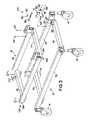
- FIG. 3is an exploded perspective view of the base frame and weigh frame of FIG. 2 showing, in the upper left-hand portion of the Fig., a load cell apparatus including an elongated mounting bar arranged for coupling to the weigh frame, a cell block beneath the mounting bar, a stud adjacent the cell block, a mounting member coupled to the base frame, and a liner between the mounting member and the stud;
- a load cell apparatusincluding an elongated mounting bar arranged for coupling to the weigh frame, a cell block beneath the mounting bar, a stud adjacent the cell block, a mounting member coupled to the base frame, and a liner between the mounting member and the stud;
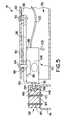
- FIG. 4is an exploded perspective view of a portion of the base frame of FIG. 3 showing the mounting member coupled to a lower frame member of the base frame, the mounting member including a square-shaped bore in an end thereof, the liner arranged for insertion into the bore, the liner including a cylindrical cavity, and a portion of the stud arranged for insertion into the cylindrical cavity of the liner;
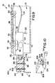
- FIG. 5is a partial sectional view of the base frame and weigh frame showing the load cell coupled to the elongated mounting bar which is coupled to a frame member of the weigh frame and showing the stud extending from the cell block to engage the liner which is mounted in the bore of the mounting member;
- FIG. 6is a top view of the liner of FIG. 5 ;
- FIG. 7is a front elevation view of the liner of FIG. 6 ;
- FIG. 8is a side elevation view of the liner of FIG. 7 ;
- FIG. 9is a partial sectional view of the base frame, the weigh frame, and a first alternative embodiment load cell apparatus in accordance with the present invention showing a stud having a cylindrical portion extending from a cell block, a mount having a bore formed therein, a quantity of material in a bottom portion of the bore, and the cylindrical portion of the stud engaging the material;
- FIG. 10is a perspective view of the mount and a portion of the stud of FIG. 9 showing that the bore is a generally square-shaped cavity and showing that the quantity of material is a flat pad;
- FIG. 11is a partial sectional view of the base frame, the weigh frame, and a second alternative embodiment load cell apparatus in accordance with the present invention showing a stud having a spherical portion extending from a cell block, a mount having a bore formed therein, a quantity of material in a bottom portion of the bore, and the spherical portion of the stud engaging the material;
- FIG. 12is a perspective view of the mount and a portion of the stud of FIG. 11 showing that the bore is a generally square-shaped cavity and showing that the quantity of material is a flat pad;
- FIG. 13is a partial sectional view of the base frame, the weigh frame, and a third alternative embodiment load cell apparatus in accordance with the present invention showing a stud having a cylindrical portion extending from a cell block, a mount having a bore formed therein, a quantity of material coating the cylindrical portion of the stud, and the coated cylindrical portion of the stud being received in the bore of the mount;
- FIG. 14is a perspective view of the mount and a portion of the stud of FIG. 13 showing that the bore is a cylindrical cavity;
- FIG. 15is a partial sectional view of the base frame, the weigh frame, and a fourth alternative embodiment load cell apparatus in accordance with the present invention showing a stud having a spherical portion extending from a cell block, a mount having a bore formed therein, and an O-ring coupled to the spherical portion of the stud; and
- FIG. 16is a perspective view of the mount and portion of the stud of FIG. 15 showing that the bore is a generally square-shaped cavity.
- the present inventionrelates to a load cell apparatus and will be described herein as used in a weigh system of a hospital bed.
- the load cell apparatus of the present inventionis not limited to use in a hospital bed and those skilled in the art will appreciate that the present invention may be used in a wide variety of applications where loads are sensed.
- a hospital bed 10includes a base frame 12 to which a plurality of casters 14 are coupled as shown in FIG. 1 .
- Illustrative bed 10also includes brake/steer control pedals 16 coupled to base frame 12 adjacent respective casters 14 .
- bed 10includes a weigh frame 18 coupled to base frame 12 , an intermediate frame 19 coupled to the weigh frame 18 , a retracting frame 20 coupled to the intermediate frame 19 , and an articulating deck 22 coupled to the intermediate frame 19 and to the retracting frame 20 .
- Deck 22includes a head section 106 , a seat section 108 , a thigh section 110 , and a foot section 112 .
- Brackets 21 on opposite sides of frame 20are configured to be coupled between the head section 106 and the thigh section 110 of deck 22 with suitable fasteners (not shown).
- Bed 10includes a headboard 24 mounted adjacent a head end 26 of bed 10 and a footboard 28 mounted to the frame adjacent a foot end 30 of bed 10 as shown in FIG. 1 .
- Bed 10further includes a pair of head end siderails 32 and a pair of foot end siderails 34 mounted to the articulating deck 22 on opposite sides of bed 10 .
- Side rails 32 , 34are movable from a lowered position shown in FIG. 1 to an elevated position (not shown) located above a top surface 36 of a mattress 38 that is supported by deck 22 .
- Controls for controlling various functions of bed 10are included in siderails 32 and in footboard 28 .
- Illustrative controls 40are located on a top inclined panel 42 and bottom inclined panel 44 on the footboard 28 .
- a cover 46is pivotably coupled to the footboard 28 for movement between a raised position, shown in FIG. 1 , exposing panel 42 and a lowered position (not shown) concealing panel 42 .
- Footboard 28also includes side bumpers 66 and hand grip apertures 68 .
- Controls 40 on footboard 28are electrically coupled to a controller 50 shown in FIG. 2 .
- Controller 50 and other bed electronicsare illustratively mounted on frame 20 .
- Signals from controls 40route to controller 50 through a connector 52 that is coupled to footboard 28 and also route through a connector 54 that is coupled to frame 20 .
- Connector 52disconnects from connector 54 when the footboard 28 is removed from frame 20 as shown in FIG. 2 .
- Footboard 28is formed to include apertures 56 that slide over posts 58 on frame 20 during installation of footboard 28 on frame 20 in the direction of arrow 60 in FIG. 2 .
- bed 10Additional details of bed 10 are disclosed in U.S. patent application Ser. No. 09/264,174 entitled PATIENT POSITION DETECTION APPARATUS FOR A BED and in U.S. patent application Ser. No. 09/263,039 entitled CASTER AND BRAKING SYSTEM, each of which are assigned to the assignee of the present invention and each of which are hereby incorporated by reference herein. As mentioned above, the details of bed 10 are given only to provide a description of one type of application in which the load cell apparatus of the present invention may be used and such details are not intended to limit the scope of the invention in any manner.
- Controls 40 on lower panel 44include controls for operating a weigh system of bed 10 .
- the weigh systemincludes load cell apparatus 100 in accordance with the present invention.
- the weigh systemalso includes patient-position sensors 114 , 120 , 122 , 124 coupled to deck 22 by suitable fasteners 116 as shown in FIG. 2 . Further details of sensors 114 , 120 , 122 , 124 are provided in U.S. patent application Ser. No. 09/264,174.
- Base frame 12includes side frame members 72 and transverse frame members 74 extending between side frame members 72 as shown, for example, in FIG. 3 .
- Weigh frame 18includes a pair of hollow side frame members 76 and a pair of transverse frame members 77 extending between side frame members 76 .
- Load cell apparatus 100includes a load member, load beam, or cell block (hereinafter “cell block 70 ”) that is mounted at one of the four corners of the weigh frame 18 .
- Strain gages(not shown) are included in each load cell apparatus 100 and are coupled to each respective cell block 70 . The strain gages operate in a conventional manner to provide an indication of the load supported by the load cell apparatus 100 .
- a known input voltageis applied to input leads (not shown) coupled to the strain gages and, as cell blocks 70 deflect due to the application of a load, the resistance of the strain gages changes resulting in a change in an output signal generated on output leads (not shown) coupled to the strain gages.
- the input and output leadsare bundled together in a cable 102 that is routed between load cell apparatus 100 and conventional signal conditioning circuitry (not shown).
- Block 70is coupled to a mounting bar 86 by suitable fasteners such as bolts 90 shown, for example, in FIGS. 2 and 3 .
- Mounting bar 86 and block 70are received in the interior region of frame member 76 and suitable fasteners, such as bolts 94 , fasten mounting bar 86 to a top wall 92 of frame member 76 as shown best in FIG. 5 .
- Spacers 96are provided between mounting bar 86 and wall 92 to provided adequate clearance for the portion of fasteners 90 located above mounting bar 86 .
- mounting bar 86is formed with integral, upwardly extending bosses that perform the same function as spacers 96 .
- a stud 78includes a hex nut portion 130 , a threaded portion 132 on one side of portion 130 , and a cylindrical portion 134 on the other side of portion 130 .
- Portion 132 of stud 76is threaded into an aperture 77 , shown in FIG. 3 , formed in block 70 until hex nut portion 130 abuts block 70 and cylindrical portion 134 extends longitudinally away from both block 70 and frame member 76 .
- Load cell apparatus 100further includes a mounting block, mounting tube, or other suitable mounting structure 82 (hereinafter referred to as “mount 82 ”) that is coupled to a top surface of frame member 74 of base frame 12 by suitable fasteners such as bolts 84 as shown in FIGS. 2–5 .
- Mount 82is formed to include a bore 140 , shown best in FIG. 4 , and load cell apparatus 100 includes a liner 142 that is received in bore 150 .
- Illustrative mount 82 and bore 140each have a generally square-shaped cross section as shown in FIG. 4 .
- liner 142is generally cube-shaped and is sized to press fit into bore 140 such that top and bottom outer surfaces 144 of liner 142 engage respective top and bottom inner surfaces 146 of mount 82 and such that a rear surface 148 of liner 142 engages a seat surface 150 of mount 82 .
- Liner 142includes side surfaces 152 that are each formed to include a protrusion 154 that enhances the press fit of liner 142 with mount 82 .
- Protrusions 154engage respective side inner surfaces 156 of mount 82 .
- Illustrative protrusions 154are generally hemispherical in shape as shown best in FIGS. 6–8 .
- Liner 142is sized so that a front surface 158 thereof is substantially flush with a front surface 160 of mount 82 .
- Liner 142is formed to include a cylindrical cavity 162 as shown, for example, in FIG. 4 .
- An opening 164 of cavity 162is located at front face 158 of liner 142 and cavity 162 is bounded by a cylindrical surface 166 that extends from opening 164 toward rear surface 148 of liner 142 .
- cavity 162terminates at an end surface 168 that is substantially parallel with and located between rear and front surfaces 148 , 158 .
- cylindrical portion 134 of stud 78is received in cavity 162 and engages cylindrical surface 166 of liner 142 .
- the diameter of cylindrical surface 166is slightly larger than the diameter of cylindrical portion 134 of stud 78 so that a small amount of clearance is provided between cylindrical portion 134 of stud 78 and cylindrical surface 166 .
- bore 162 of liner 142is configured such that a gap, shown in FIG. 5 , exists between end surface 168 of liner 142 and an end surface 170 of cylindrical portion 134 of stud 78 .
- cell block 70 , stud 78 , and mount 82are made of a metal material
- liner 142is made of a material that is more lubrous than the material from which mount 82 and/or stud 78 is made.
- mount 82is made of FC-0208-50 steel and is zinc plated
- cell block 70is made of aluminum
- stud 78is either 4140 C.D.S. steel or 4142 C.D.S. steel.
- Examples of materials that are suitable for liner 142 when stud 78 and mount 82 are made of steelinclude TEFLONO material; urethane material; and neoprene material.
- liner 142is made of ninety-five (95) durometer Shore A urethane.
- the material from which cell block 70 , stud 78 , mount 82 , and liner 142is not limited to those materials listed above. Therefore, those skilled in the art will appreciate that liner 142 may be made of other suitable material within the scope of the present invention so long as such material is more lubrous than the material from which mount 82 and/or stud 78 is made.
- cell block 70 of load cell apparatus 100includes a first portion 88 that abuts mounting bar 86 , a second portion 98 that is spaced from mounting bar 86 by a slight amount, and a reduced-thickness portion 104 interconnecting portions 88 , 98 .
- portion 88Increasing the weight supported by weigh frame 18 causes portion 88 to move downwardly in the direction of double arrow 103 , shown in FIG. 5 , thereby causing portion 104 to flex.
- the strain gages(not shown) are coupled to portion 104 and therefore, flexing of portion 104 flexes the strain gages to change an output signal which provides an indication of the weight supported by weigh frame 18 .
- the output signalis communicated to conventional signal conditioning circuitry by output leads which are contained in cable 102 .
- portion 104 of cell block 70During flexing of portion 104 of cell block 70 , cylindrical portion 134 of stud 78 moves along cylindrical surface 166 by a small amount relative to liner 142 and relative to mount 82 . Thus, sliding bearing contact exists between stud 78 and liner 142 . Frictional forces between stud 78 and liner 142 have a tendency to inhibit stud 78 from moving relative to liner 142 and relative to mount 82 . In the event that stud 78 ceases to move by some minute amount relative to liner 142 due to friction, then portion 104 of cell block 70 is prevented from flexing by a corresponding minute amount which introduces a source of error that results in an inaccurate output signal.
- load cell apparatus 200is shown in FIGS. 9 and 10 .
- Many of the components of load cell apparatus 200are substantially the same as components of load cell apparatus 100 and therefore, like reference numerals are used to denote like components.
- Load cell apparatus 200includes a mount 202 having a bore 204 formed therein. Bore 204 has a substantially square-shaped cross section and extends from an opening 206 formed at a front surface 208 of mount 202 to an end surface 210 that is positioned to lie between front surface 208 and a rear surface 212 of mount 202 .
- Load cell apparatus 200includes a liner 214 as shown in FIGS. 9 and 10 .
- Liner 214comprises a quantity of material configured as a flat pad that is received in the bore 202 .
- Liner 214may be made of any of the materials described above in connection with liner 142 so long as liner 214 is more lubrous than the material from which mount 202 and/or stud 78 is made.
- Liner 214is either press fit between inner side walls 216 of mount 202 or is adhered to a bottom inner surface 218 of mount 202 or both.
- cylindrical portion 134 of stud 78rests upon liner 214 .
- load cell apparatus 300includes a mount 302 having a bore 304 formed therein. Bore 304 has a substantially square-shaped cross section and extends from an opening 306 formed at a front surface 308 of mount 302 to an end surface 310 that is positioned to lie between front surface 308 and a rear surface 312 of mount 302 .
- Load cell apparatus 300also includes a stud 378 having a hex nut portion 380 , a connector portion 382 extending from portion 380 , and a spherical portion 384 appended to portion 382 as shown in FIG. 11 .
- stud 378includes a threaded portion (not shown) that is substantially similar to threaded portion 132 of stud 78 of load cell apparatus 100 .
- Load cell apparatus 300further includes a liner 314 as shown in FIGS. 11 and 12 .
- Liner 314comprises a quantity of material configured as a flat pad that is received in bore 302 .
- Liner 314may be made of any of the materials described above in connection with liner 142 so long as liner 314 is more lubrous than the material from which mount 302 and/or stud 378 is made.
- Liner 314is either press fit between inner side walls 316 of mount 302 or is adhered to a bottom inner surface 318 of mount 302 or both.
- spherical portion 384 of stud 378rests upon liner 314 .
- FIGS. 13 and 14A fourth alternative embodiment load cell apparatus 400 is shown in FIGS. 13 and 14 . Many of the components of load cell apparatus 400 are substantially the same as components of load cell apparatus 100 and therefore, like reference numerals are used to denote like components.
- Load cell apparatus 400includes a mount 402 having a bore 404 formed therein. Bore 404 is bounded by a cylindrical bore surface 422 that extends from an opening 406 formed at a front surface 408 of mount 402 to an end surface 410 that is positioned to lie between front surface 408 and a rear surface 412 of mount 402 .
- Load cell apparatus 400includes a liner 414 as shown in FIGS. 9 and 10 .
- Liner 414comprises a quantity of material that coats cylindrical portion 134 of stud 78 .
- Liner 414may be made of any of the materials described above in connection with liner 142 so long as liner 414 is more lubrous than the material from which mount 402 and/or stud 78 is made.
- Liner 414is either press fit onto cylindrical portion 134 of stud 78 or is adhered thereto or both.
- liner 414may be fashioned as a cap, as shown in FIG. 13 , or a cylindrical sleeve (not shown) that has an open end adjacent end surface 170 of cylindrical portion 134 of stud 78 .
- the cylindrical outer surface 420 of liner 414engages cylindrical bore surface 422 of mount 402 .
- the diameter of bore surface 222is slightly larger than the diameter of outer surface 420 of liner 414 to provide a small amount of diametral clearance therebetween.
- bore 404 of mount 402is sized such that axial clearance exits between an end surface 424 of liner and end surface 410 .
- load cell apparatus 500includes a mount 502 having a bore 504 formed therein. Bore 504 has a substantially square-shaped cross section and extends from an opening 506 formed at a front surface 508 of mount 502 to an end surface 510 that is positioned to lie between front surface 508 and a rear surface 512 of mount 502 .
- Load cell apparatus 500also includes a stud 578 having a hex nut portion 580 , a connector portion 582 extending from portion 580 , and a spherical portion 584 appended to portion 582 as shown in FIG. 15 .
- stud 578also includes a threaded portion (not shown) that is substantially similar to threaded portion 132 of stud 78 of load cell apparatus 100 .
- Load cell apparatus 500includes a liner 514 as shown in FIGS. 15 and 16 .
- Liner 514comprises a quantity of material fashioned as an O-ring that is coupled to spherical portion 584 .
- spherical portion 584is coated with a quantity of material to provide the liner.
- Liner 514may be made of any of the materials described above in connection with liner 142 so long as liner 514 is more lubrous than the material from which mount 502 and/or stud 578 is made.
- Liner 514is received in a groove formed around spherical portion 584 .
- Optionally adhesivemay be used between O-ring 514 and portion 584 .
- O-ring 514engages a bottom inner surface 522 of mount 502 .
- the bores formed in the mounts of the respective above-described embodimentsmay have shapes other than those illustrated without exceeding the scope of the present invention.
- bores that are shown as having square-shaped cross sectionsmay instead have cylindrical cross sections and vice versa.
- the bores formed in the mounts of each of the respective embodimentsmay be hexagonal, octagonal, etc. and the liners used with such mounts would be shaped accordingly.
- the bores formed in the mounts of the respective above-described embodimentsterminate within the respective mounts, it is within the scope of the invention as presently perceived for the bores to extend all the way through the mounts such that the respective mounts are generally tubular.
- the load cell apparatusare described herein as being coupled to a base frame 12 and a weigh frame 18 , it is within the scope of the present invention for the load cell apparatus to couple to any type of structure or support. Therefore, the term “structure” as used in the claims is intended to be non-limiting and to mean any and all types of frames, bases, structures, supports, pedestals, decks, etc.
- the each of the load cell apparatus described hereininclude cell block 70 , those skilled in the art will appreciate that other types of cell blocks, load beams, and load members may be used in lieu of cell block 70 . Therefore, the term “cell block” as used in the claims is intended to mean load members of all types and of all shapes.
Landscapes
- Physics & Mathematics (AREA)
- General Physics & Mathematics (AREA)
- Invalid Beds And Related Equipment (AREA)
Abstract
Description
Claims (65)
Priority Applications (1)
| Application Number | Priority Date | Filing Date | Title |
|---|---|---|---|
| US09/669,707US6924441B1 (en) | 1999-09-29 | 2000-09-26 | Load cell apparatus |
Applications Claiming Priority (2)
| Application Number | Priority Date | Filing Date | Title |
|---|---|---|---|
| US15658199P | 1999-09-29 | 1999-09-29 | |
| US09/669,707US6924441B1 (en) | 1999-09-29 | 2000-09-26 | Load cell apparatus |
Publications (1)
| Publication Number | Publication Date |
|---|---|
| US6924441B1true US6924441B1 (en) | 2005-08-02 |
Family
ID=34798412
Family Applications (1)
| Application Number | Title | Priority Date | Filing Date |
|---|---|---|---|
| US09/669,707Expired - LifetimeUS6924441B1 (en) | 1999-09-29 | 2000-09-26 | Load cell apparatus |
Country Status (1)
| Country | Link |
|---|---|
| US (1) | US6924441B1 (en) |
Cited By (43)
| Publication number | Priority date | Publication date | Assignee | Title |
|---|---|---|---|---|
| US20050284669A1 (en)* | 2004-06-23 | 2005-12-29 | Dipaola David J | Sensor mounting apparatus for minimizing parasitic stresss |
| US20050284668A1 (en)* | 2003-03-05 | 2005-12-29 | Kabushiki Kaisha Imasen Denki Seisakusho | On-board person load sensor |
| EP1635153A2 (en)* | 2004-09-13 | 2006-03-15 | Hill-Rom Services, Inc. | Load cell for a hospital bed |
| US20060266791A1 (en)* | 2005-03-25 | 2006-11-30 | Walter Koch | Work-table |
| US20070130692A1 (en)* | 2005-10-27 | 2007-06-14 | Guy Lemire | Ergonomic control apparatus for a patient support apparatus |
| US20070180616A1 (en)* | 2006-02-08 | 2007-08-09 | Hill-Rom Services, Inc. | User module for a patient support |
| WO2007129239A1 (en)* | 2006-05-05 | 2007-11-15 | Philips Intellectual Property & Standards Gmbh | Sensor unit, bed for a patient and method of modifying a patient´s bed |
| US20080006452A1 (en)* | 2006-07-07 | 2008-01-10 | Mettler-Toledo Ag | Weighing module |
| US20080006451A1 (en)* | 2006-07-07 | 2008-01-10 | Mettler-Toledo Ag | Weighing module |
| US7381910B1 (en) | 2007-04-13 | 2008-06-03 | Anodyne Medical Devices, Llc | Sensor frame for generating a weight signal of a curved object |
| US7676862B2 (en) | 2004-09-13 | 2010-03-16 | Kreg Medical, Inc. | Siderail for hospital bed |
| US7743441B2 (en) | 2004-09-13 | 2010-06-29 | Kreg Therapeutics, Inc. | Expandable width bed |
| US7757318B2 (en) | 2004-09-13 | 2010-07-20 | Kreg Therapeutics, Inc. | Mattress for a hospital bed |
| US7779494B2 (en) | 2004-09-13 | 2010-08-24 | Kreg Therapeutics, Inc. | Bed having fixed length foot deck |
| US20110010858A1 (en)* | 2008-02-15 | 2011-01-20 | Milan Tesar | Positioning mechanism of a bed |
| EP2422758A2 (en) | 2010-08-26 | 2012-02-29 | Hill-Rom Services, Inc. | Incline based bed height |
| US20130146371A1 (en)* | 2011-12-08 | 2013-06-13 | Caremed Supply Inc. | Real-time weighing device for use with hospital bed |
| US20130153307A1 (en)* | 2010-09-01 | 2013-06-20 | Ronny Van De Vliet | Weighing module for static or dynamic weighing of loads and force transmission applied thereby |
| US20130319775A1 (en)* | 2012-06-05 | 2013-12-05 | Liko Research & Development Ab | Weight scale for a patient lift system, a control system for the weight scale, and a method for weighing a patient supported on the weight scale |
| US20140069729A1 (en)* | 2012-09-10 | 2014-03-13 | Caremed Supply Inc. | Real-time weight measuring system for hospital bed |
| US9119753B2 (en) | 2008-06-27 | 2015-09-01 | Kreg Medical, Inc. | Bed with modified foot deck |
| US20150300872A1 (en)* | 2012-01-20 | 2015-10-22 | Showa Denko K.K. | Bed having load detection function and load detector for bed |
| CN105377208A (en)* | 2013-07-16 | 2016-03-02 | 昭和电工株式会社 | Bed with load detection function and load detector for bed |
| EP3015098A2 (en) | 2014-10-31 | 2016-05-04 | Hill-Rom Services, Inc. | Equipment, dressing and garment wireless connectiviity to a patient bed |
| EP3023897A1 (en) | 2014-11-18 | 2016-05-25 | Hill-Rom Services, Inc. | Catheter monitor integration with patient support and healthcare communication systems |
| US9492341B2 (en) | 2010-10-08 | 2016-11-15 | Hill-Rom Services, Inc. | Hospital bed with graphical user interface having advanced functionality |
| US9539155B2 (en) | 2012-10-26 | 2017-01-10 | Hill-Rom Services, Inc. | Control system for patient support apparatus |
| US9754476B2 (en) | 2014-08-27 | 2017-09-05 | Umano Medical Inc. | Hospital bed with patient weight and displacement sensors |
| US9875633B2 (en) | 2014-09-11 | 2018-01-23 | Hill-Rom Sas | Patient support apparatus |
| US10045715B2 (en) | 2015-04-27 | 2018-08-14 | Hill-Rom Services, Inc. | Self-compensating bed scale system for removable components |
| US10054479B2 (en) | 2015-05-05 | 2018-08-21 | Hill-Rom Services, Inc. | Bed with automatic weight offset detection and modification |
| US10260933B2 (en) | 2015-06-30 | 2019-04-16 | Stryker Corporation | Person support apparatuses with load cell error detection |
| US10330522B2 (en) | 2015-12-17 | 2019-06-25 | Stryker Corporation | Person support apparatus with exit detection system and/or scale system |
| US10634549B2 (en) | 2016-02-11 | 2020-04-28 | Hill-Rom Services, Inc. | Hospital bed scale calibration methods and patient position monitoring methods |
| EP3675131A1 (en) | 2018-12-27 | 2020-07-01 | Hill-Rom Services, Inc. | System and method for caregiver availability determination |
| US10898400B2 (en) | 2016-12-01 | 2021-01-26 | Stryker Corporation | Person support apparatuses with load cells |
| US10987262B2 (en) | 2013-03-15 | 2021-04-27 | Stryker Corporation | Medical support apparatus |
| US20210401654A1 (en)* | 2017-05-31 | 2021-12-30 | Mizuho Osi | System, apparatus and method for supporting and/or positioning a patient before, during, or after a medical procedure |
| US11395783B2 (en)* | 2019-07-31 | 2022-07-26 | Stryker Corporation | Patient support apparatus with load cell assemblies |
| US11491062B2 (en) | 2019-04-18 | 2022-11-08 | Stryker Corporation | Patient handling apparatus with load sensor |
| US12056562B2 (en) | 2021-11-09 | 2024-08-06 | NorviTech, Inc. | Device for measuring nutritional intake |
| US12150908B2 (en) | 2014-04-18 | 2024-11-26 | Kreg Medical, Inc. | Patient support with stand-up and sit features |
| US12251345B2 (en) | 2019-11-27 | 2025-03-18 | Stryker Corporation | Patient support apparatus with load cell assemblies |
Citations (56)
| Publication number | Priority date | Publication date | Assignee | Title |
|---|---|---|---|---|
| US2990899A (en) | 1958-11-24 | 1961-07-04 | Bella Isabelle D De | Bed patient weighing means |
| US3217818A (en) | 1964-04-06 | 1965-11-16 | Harvey J Engelsher | Pneumatic weighing device |
| US3338323A (en) | 1965-01-12 | 1967-08-29 | Francis Roe C | Hydraulic weighing apparatus with rebalancing means for determining load differential |
| US3360062A (en) | 1964-12-14 | 1967-12-26 | James A Potter | Scale for measuring change of weight of clinical patient |
| US3512595A (en) | 1967-09-27 | 1970-05-19 | Blh Electronics | Suspension-type strain gage transducer structure |
| US3656478A (en) | 1970-04-13 | 1972-04-18 | Brookline Instr Co | Infusion monitor utilizing weight detecting means |
| US3722611A (en) | 1970-02-05 | 1973-03-27 | E Tirkkonen | Patient scales |
| US3773124A (en) | 1972-08-16 | 1973-11-20 | Tron Corp K | Electronic weight transmitter |
| US3795284A (en) | 1972-01-03 | 1974-03-05 | M Mracek | Portable support and weigher for a bed patient |
| US3876018A (en) | 1972-01-03 | 1975-04-08 | Said Mracek By Said Bauer | Portable support for a bed patient |
| US3961675A (en) | 1975-05-01 | 1976-06-08 | Vernon Harold Siegel | Portable housing for weighing systems |
| US3998790A (en) | 1970-02-18 | 1976-12-21 | Aktiebolaget Hassle | Phenoxy-hydroxypropylamines, their preparation, and method and pharmaceutical preparations for treating cardiovascular diseases |
| US4006789A (en) | 1976-01-21 | 1977-02-08 | Acme Scale Company | Scale for weighing hospital patients in their horizontal position |
| US4015677A (en) | 1975-07-25 | 1977-04-05 | The United States Of America As Represented By The Secretary Of The Navy | Automatic patient weighing system |
| US4023633A (en) | 1975-12-22 | 1977-05-17 | Swersey Burt L | Flexure scale |
| US4033420A (en) | 1976-05-20 | 1977-07-05 | Brookline Instrument Company, Inc. | Weighing scale |
| US4215754A (en) | 1978-11-20 | 1980-08-05 | Structural Instrumentation, Inc. | Load measuring system for leaf spring suspensions |
| US4281730A (en) | 1980-01-15 | 1981-08-04 | Swersey Burt L | Scale |
| US4363368A (en) | 1981-03-13 | 1982-12-14 | Health Care Innovations, Inc. | Medical patient weighing scale |
| US4411327A (en) | 1981-05-14 | 1983-10-25 | Hottinger Baldwin Measurements, Inc. | Apparatus for applying a load to a strain gage transducer beam |
| US4438823A (en) | 1982-08-09 | 1984-03-27 | Dbi Industries, Inc. | Load cell |
| US4483404A (en) | 1983-08-30 | 1984-11-20 | Benny N. Dillon | Self-aligning scale assembly |
| US4487276A (en) | 1983-05-03 | 1984-12-11 | Swersey Burt L | Scale of flat construction |
| US4492281A (en) | 1982-03-01 | 1985-01-08 | Scans Associates, Inc. | Weigh scale |
| US4539560A (en) | 1982-12-10 | 1985-09-03 | Hill-Rom Company, Inc. | Bed departure detection system |
| US4550793A (en) | 1981-05-13 | 1985-11-05 | Precision Engineering Products Limited (Suffolk) | Method and apparatus for checking the weight of a moving article |
| US4551882A (en) | 1981-05-04 | 1985-11-12 | Cobe Asdt, Inc. | Scale of flat construction |
| US4601356A (en) | 1985-02-01 | 1986-07-22 | Muccillo Jr Vincent J | Suspended platform scale structure |
| US4629015A (en) | 1984-11-28 | 1986-12-16 | Cobe Asdt, Inc. | Weight monitoring system |
| US4751754A (en) | 1987-04-02 | 1988-06-21 | Hill-Rom Company, Inc. | Dual hydraulic hospital bed with emergency bypass circuit |
| US4793428A (en) | 1988-02-29 | 1988-12-27 | Cobe Asdt, Inc. | Hospital bed with an integrated scale |
| EP0322994A2 (en) | 1987-12-28 | 1989-07-05 | HILL-ROM COMPANY, INC. (an Indiana corporation) | Hospital bed for weighing patients |
| US4899840A (en) | 1989-06-22 | 1990-02-13 | Boubille Jacques C | Apparatus for weighing a pallet with a load thereon for use with a vehicle having tines or the like |
| US4926951A (en) | 1989-06-26 | 1990-05-22 | Ssi Medical Services, Inc. | Weigh bed |
| US4934468A (en) | 1987-12-28 | 1990-06-19 | Hill-Rom Company, Inc. | Hospital bed for weighing patients |
| US4961470A (en) | 1989-05-25 | 1990-10-09 | Hill-Rom Company, Inc. | Weigh bed having vertical load link |
| US4974692A (en)* | 1989-06-26 | 1990-12-04 | Ssi Medical Services, Inc. | Weigh bed |
| US5173977A (en) | 1991-10-04 | 1992-12-29 | Hill-Rom Company, Inc. | Load cell mount for hospital weigh bed |
| US5269388A (en) | 1991-11-12 | 1993-12-14 | Stress-Tek, Inc. | Weighing bed |
| US5276432A (en) | 1992-01-15 | 1994-01-04 | Stryker Corporation | Patient exit detection mechanism for hospital bed |
| US5393935A (en) | 1993-07-09 | 1995-02-28 | Ch Administration, Inc. | Portable scale |
| USRE35301E (en) | 1985-09-17 | 1996-07-23 | Stress-Tek, Inc. | On-board load cell |
| EP0744598A1 (en) | 1995-05-24 | 1996-11-27 | Petrus Wilhelmus Maria Welvaarts | Weighing apparatus |
| US5600104A (en) | 1993-10-20 | 1997-02-04 | Structural Instrumentation, Inc. | Load cell having reduced sensitivity to non-symmetrical beam loading |
| US5672849A (en) | 1994-03-31 | 1997-09-30 | Hill-Rom Company, Inc. | Patient weigh scale |
| US5715548A (en) | 1994-01-25 | 1998-02-10 | Hill-Rom, Inc. | Chair bed |
| EP0838659A2 (en) | 1996-10-23 | 1998-04-29 | Hill-Rom, Inc. | Hospital bed scale mounting apparatus |
| US5747745A (en)* | 1995-07-26 | 1998-05-05 | Tedea-Huntleigh Intl. Ltd. | Weighting device for bedridden patients |
| US5771511A (en) | 1995-08-04 | 1998-06-30 | Hill-Rom, Inc. | Communication network for a hospital bed |
| US5823278A (en)* | 1994-10-13 | 1998-10-20 | Future Systems, Inc. | Caster mounted weighing system |
| US5861581A (en) | 1996-12-11 | 1999-01-19 | Stress-Tek, Inc. | Equalizer hanger system for on-board weighing |
| US5906016A (en) | 1988-03-23 | 1999-05-25 | Hill-Rom | Patient care system |
| WO2000051541A2 (en) | 1999-03-05 | 2000-09-08 | Hill-Rom, Inc. | Patient position detection apparatus for a bed |
| US6150619A (en) | 1996-06-28 | 2000-11-21 | Borngasser; Johannes | Support base for a measuring cell |
| US6362439B1 (en)* | 2000-04-21 | 2002-03-26 | Stress-Tek, Inc. | Load-cell mounting assembly |
| US6680443B2 (en)* | 2001-06-22 | 2004-01-20 | Hill-Rom Services, Inc. | Load cell apparatus having a gap measuring device |
- 2000
- 2000-09-26USUS09/669,707patent/US6924441B1/ennot_activeExpired - Lifetime
Patent Citations (58)
| Publication number | Priority date | Publication date | Assignee | Title |
|---|---|---|---|---|
| US2990899A (en) | 1958-11-24 | 1961-07-04 | Bella Isabelle D De | Bed patient weighing means |
| US3217818A (en) | 1964-04-06 | 1965-11-16 | Harvey J Engelsher | Pneumatic weighing device |
| US3360062A (en) | 1964-12-14 | 1967-12-26 | James A Potter | Scale for measuring change of weight of clinical patient |
| US3338323A (en) | 1965-01-12 | 1967-08-29 | Francis Roe C | Hydraulic weighing apparatus with rebalancing means for determining load differential |
| US3512595A (en) | 1967-09-27 | 1970-05-19 | Blh Electronics | Suspension-type strain gage transducer structure |
| US3722611A (en) | 1970-02-05 | 1973-03-27 | E Tirkkonen | Patient scales |
| US3998790A (en) | 1970-02-18 | 1976-12-21 | Aktiebolaget Hassle | Phenoxy-hydroxypropylamines, their preparation, and method and pharmaceutical preparations for treating cardiovascular diseases |
| US3656478A (en) | 1970-04-13 | 1972-04-18 | Brookline Instr Co | Infusion monitor utilizing weight detecting means |
| US3795284A (en) | 1972-01-03 | 1974-03-05 | M Mracek | Portable support and weigher for a bed patient |
| US3876018A (en) | 1972-01-03 | 1975-04-08 | Said Mracek By Said Bauer | Portable support for a bed patient |
| US3773124A (en) | 1972-08-16 | 1973-11-20 | Tron Corp K | Electronic weight transmitter |
| US3961675A (en) | 1975-05-01 | 1976-06-08 | Vernon Harold Siegel | Portable housing for weighing systems |
| US4015677A (en) | 1975-07-25 | 1977-04-05 | The United States Of America As Represented By The Secretary Of The Navy | Automatic patient weighing system |
| US4023633A (en) | 1975-12-22 | 1977-05-17 | Swersey Burt L | Flexure scale |
| US4006789A (en) | 1976-01-21 | 1977-02-08 | Acme Scale Company | Scale for weighing hospital patients in their horizontal position |
| US4033420A (en) | 1976-05-20 | 1977-07-05 | Brookline Instrument Company, Inc. | Weighing scale |
| US4215754A (en) | 1978-11-20 | 1980-08-05 | Structural Instrumentation, Inc. | Load measuring system for leaf spring suspensions |
| US4281730A (en) | 1980-01-15 | 1981-08-04 | Swersey Burt L | Scale |
| US4363368A (en) | 1981-03-13 | 1982-12-14 | Health Care Innovations, Inc. | Medical patient weighing scale |
| US4551882A (en) | 1981-05-04 | 1985-11-12 | Cobe Asdt, Inc. | Scale of flat construction |
| US4550793A (en) | 1981-05-13 | 1985-11-05 | Precision Engineering Products Limited (Suffolk) | Method and apparatus for checking the weight of a moving article |
| US4411327A (en) | 1981-05-14 | 1983-10-25 | Hottinger Baldwin Measurements, Inc. | Apparatus for applying a load to a strain gage transducer beam |
| US4492281A (en) | 1982-03-01 | 1985-01-08 | Scans Associates, Inc. | Weigh scale |
| US4438823A (en) | 1982-08-09 | 1984-03-27 | Dbi Industries, Inc. | Load cell |
| US4539560A (en) | 1982-12-10 | 1985-09-03 | Hill-Rom Company, Inc. | Bed departure detection system |
| US4487276A (en) | 1983-05-03 | 1984-12-11 | Swersey Burt L | Scale of flat construction |
| US4483404A (en) | 1983-08-30 | 1984-11-20 | Benny N. Dillon | Self-aligning scale assembly |
| US4629015A (en) | 1984-11-28 | 1986-12-16 | Cobe Asdt, Inc. | Weight monitoring system |
| US4601356A (en) | 1985-02-01 | 1986-07-22 | Muccillo Jr Vincent J | Suspended platform scale structure |
| USRE35301E (en) | 1985-09-17 | 1996-07-23 | Stress-Tek, Inc. | On-board load cell |
| US4751754A (en) | 1987-04-02 | 1988-06-21 | Hill-Rom Company, Inc. | Dual hydraulic hospital bed with emergency bypass circuit |
| EP0322994A2 (en) | 1987-12-28 | 1989-07-05 | HILL-ROM COMPANY, INC. (an Indiana corporation) | Hospital bed for weighing patients |
| US4934468A (en) | 1987-12-28 | 1990-06-19 | Hill-Rom Company, Inc. | Hospital bed for weighing patients |
| US4953244A (en) | 1987-12-28 | 1990-09-04 | Hill-Rom Company, Inc. | Hospital bed for weighing patients |
| US4793428A (en) | 1988-02-29 | 1988-12-27 | Cobe Asdt, Inc. | Hospital bed with an integrated scale |
| US5906016A (en) | 1988-03-23 | 1999-05-25 | Hill-Rom | Patient care system |
| US4961470A (en) | 1989-05-25 | 1990-10-09 | Hill-Rom Company, Inc. | Weigh bed having vertical load link |
| US4899840A (en) | 1989-06-22 | 1990-02-13 | Boubille Jacques C | Apparatus for weighing a pallet with a load thereon for use with a vehicle having tines or the like |
| US4974692A (en)* | 1989-06-26 | 1990-12-04 | Ssi Medical Services, Inc. | Weigh bed |
| US4926951A (en) | 1989-06-26 | 1990-05-22 | Ssi Medical Services, Inc. | Weigh bed |
| US5173977A (en) | 1991-10-04 | 1992-12-29 | Hill-Rom Company, Inc. | Load cell mount for hospital weigh bed |
| US5269388A (en) | 1991-11-12 | 1993-12-14 | Stress-Tek, Inc. | Weighing bed |
| US5276432A (en) | 1992-01-15 | 1994-01-04 | Stryker Corporation | Patient exit detection mechanism for hospital bed |
| US5393935A (en) | 1993-07-09 | 1995-02-28 | Ch Administration, Inc. | Portable scale |
| US5600104A (en) | 1993-10-20 | 1997-02-04 | Structural Instrumentation, Inc. | Load cell having reduced sensitivity to non-symmetrical beam loading |
| US5715548A (en) | 1994-01-25 | 1998-02-10 | Hill-Rom, Inc. | Chair bed |
| US5672849A (en) | 1994-03-31 | 1997-09-30 | Hill-Rom Company, Inc. | Patient weigh scale |
| US5823278A (en)* | 1994-10-13 | 1998-10-20 | Future Systems, Inc. | Caster mounted weighing system |
| EP0744598A1 (en) | 1995-05-24 | 1996-11-27 | Petrus Wilhelmus Maria Welvaarts | Weighing apparatus |
| US5747745A (en)* | 1995-07-26 | 1998-05-05 | Tedea-Huntleigh Intl. Ltd. | Weighting device for bedridden patients |
| US5771511A (en) | 1995-08-04 | 1998-06-30 | Hill-Rom, Inc. | Communication network for a hospital bed |
| US6150619A (en) | 1996-06-28 | 2000-11-21 | Borngasser; Johannes | Support base for a measuring cell |
| EP0838659A2 (en) | 1996-10-23 | 1998-04-29 | Hill-Rom, Inc. | Hospital bed scale mounting apparatus |
| US5859390A (en)* | 1996-10-23 | 1999-01-12 | Hill-Rom, Inc. | Hospital bed scale mounting apparatus |
| US5861581A (en) | 1996-12-11 | 1999-01-19 | Stress-Tek, Inc. | Equalizer hanger system for on-board weighing |
| WO2000051541A2 (en) | 1999-03-05 | 2000-09-08 | Hill-Rom, Inc. | Patient position detection apparatus for a bed |
| US6362439B1 (en)* | 2000-04-21 | 2002-03-26 | Stress-Tek, Inc. | Load-cell mounting assembly |
| US6680443B2 (en)* | 2001-06-22 | 2004-01-20 | Hill-Rom Services, Inc. | Load cell apparatus having a gap measuring device |
Non-Patent Citations (5)
| Title |
|---|
| "Patient Bed Scales", Health Devices, Feb. 1984. |
| Hill-Rom, Inc. "A Hill-Rom Solution Advance Series Be", brochure, 1996. |
| Hill-Rom, Inc., "A Hill-Rom Solution Century CC Bed", brochure, 1996. |
| Hill-Rom, Inc., "A Hill-Rom Solution Totalcare Bed System", brochure, 1998. |
| Hill-Rom, Inc., "The Century CC Bed from Hill-Rom", brochure, 1992. |
Cited By (85)
| Publication number | Priority date | Publication date | Assignee | Title |
|---|---|---|---|---|
| US20050284668A1 (en)* | 2003-03-05 | 2005-12-29 | Kabushiki Kaisha Imasen Denki Seisakusho | On-board person load sensor |
| US7189931B2 (en)* | 2003-03-05 | 2007-03-13 | Kabushiki Kaisha Imasen Denki Seisakusho | Seat occupant load sensor |
| US7112749B2 (en)* | 2004-06-23 | 2006-09-26 | Sensata Technologies, Inc. | Sensor mounting apparatus for minimizing parasitic stress |
| US20050284669A1 (en)* | 2004-06-23 | 2005-12-29 | Dipaola David J | Sensor mounting apparatus for minimizing parasitic stresss |
| US20070107948A1 (en)* | 2004-09-13 | 2007-05-17 | Metz Darrell L | Load cell to frame interface for hospital bed |
| US8069514B2 (en) | 2004-09-13 | 2011-12-06 | Kreg Medical, Inc. | Expandable width bed |
| US7176391B2 (en) | 2004-09-13 | 2007-02-13 | Hill-Rom Services, Inc. | Load cell to frame interface for hospital bed |
| US20060059814A1 (en)* | 2004-09-13 | 2006-03-23 | Metz Darrell L | Load cell to frame interface for hospital bed |
| US7676862B2 (en) | 2004-09-13 | 2010-03-16 | Kreg Medical, Inc. | Siderail for hospital bed |
| US7743441B2 (en) | 2004-09-13 | 2010-06-29 | Kreg Therapeutics, Inc. | Expandable width bed |
| EP1635153A2 (en)* | 2004-09-13 | 2006-03-15 | Hill-Rom Services, Inc. | Load cell for a hospital bed |
| US7757318B2 (en) | 2004-09-13 | 2010-07-20 | Kreg Therapeutics, Inc. | Mattress for a hospital bed |
| US8056160B2 (en) | 2004-09-13 | 2011-11-15 | Kreg Medical, Inc. | Siderail for hospital bed |
| US7779494B2 (en) | 2004-09-13 | 2010-08-24 | Kreg Therapeutics, Inc. | Bed having fixed length foot deck |
| US7335839B2 (en) | 2004-09-13 | 2008-02-26 | Hill-Rom Services, Inc. | Load cell interface for a bed having a stud receiver with a roller axis parallel with an axis of a load cell stud |
| US20060266791A1 (en)* | 2005-03-25 | 2006-11-30 | Walter Koch | Work-table |
| US7779493B2 (en)* | 2005-10-27 | 2010-08-24 | Stryker Corporation | Ergonomic control apparatus for a patient support apparatus |
| US20070130692A1 (en)* | 2005-10-27 | 2007-06-14 | Guy Lemire | Ergonomic control apparatus for a patient support apparatus |
| US20070180616A1 (en)* | 2006-02-08 | 2007-08-09 | Hill-Rom Services, Inc. | User module for a patient support |
| US11617698B2 (en) | 2006-02-08 | 2023-04-04 | Hill-Rom Services, Inc. | User module for a patient support apparatus |
| US10842695B2 (en) | 2006-02-08 | 2020-11-24 | Hill-Rom Services, Inc. | User module for a patient support apparatus |
| US11273088B2 (en) | 2006-02-08 | 2022-03-15 | Hill-Rom Services, Inc. | User module for a patient support apparatus |
| US11786428B2 (en) | 2006-02-08 | 2023-10-17 | Hill-Rom Services, Inc. | User module for a patient support apparatus |
| US9827157B2 (en) | 2006-02-08 | 2017-11-28 | Hill-Rom Services, Inc. | User module for a patient support |
| WO2007129239A1 (en)* | 2006-05-05 | 2007-11-15 | Philips Intellectual Property & Standards Gmbh | Sensor unit, bed for a patient and method of modifying a patient´s bed |
| US20090178199A1 (en)* | 2006-05-05 | 2009-07-16 | Koninklijke Philips Electronics N.V. | Sensor unit, bed for a patient and method of modifying a patient's bed |
| US7361852B2 (en)* | 2006-07-07 | 2008-04-22 | Mettler-Toledo Ag | Weighing module |
| US20080006452A1 (en)* | 2006-07-07 | 2008-01-10 | Mettler-Toledo Ag | Weighing module |
| US20080006451A1 (en)* | 2006-07-07 | 2008-01-10 | Mettler-Toledo Ag | Weighing module |
| US7371978B2 (en)* | 2006-07-07 | 2008-05-13 | Mettler-Toledo Ag | Thermally insulated weighing module |
| US7381910B1 (en) | 2007-04-13 | 2008-06-03 | Anodyne Medical Devices, Llc | Sensor frame for generating a weight signal of a curved object |
| US8112836B2 (en) | 2008-02-15 | 2012-02-14 | Linet Spol. S.R.O. | Positioning mechanism of a bed |
| US20110010858A1 (en)* | 2008-02-15 | 2011-01-20 | Milan Tesar | Positioning mechanism of a bed |
| US10617582B2 (en) | 2008-06-27 | 2020-04-14 | Kreg Medical, Inc. | Bed with modified foot deck |
| US9119753B2 (en) | 2008-06-27 | 2015-09-01 | Kreg Medical, Inc. | Bed with modified foot deck |
| US12208041B2 (en) | 2008-06-27 | 2025-01-28 | Kreg Medical, Inc. | Bed with frame assembly |
| EP2422758A2 (en) | 2010-08-26 | 2012-02-29 | Hill-Rom Services, Inc. | Incline based bed height |
| US20130153307A1 (en)* | 2010-09-01 | 2013-06-20 | Ronny Van De Vliet | Weighing module for static or dynamic weighing of loads and force transmission applied thereby |
| US10857050B2 (en) | 2010-10-08 | 2020-12-08 | Hill-Rom Services, Inc. | Hospital bed control and charting |
| US11707391B2 (en) | 2010-10-08 | 2023-07-25 | Hill-Rom Services, Inc. | Hospital bed having rounding checklist |
| US12419798B2 (en) | 2010-10-08 | 2025-09-23 | Hill-Rom Services, Inc. | Hospital bed having patient association control |
| US9492341B2 (en) | 2010-10-08 | 2016-11-15 | Hill-Rom Services, Inc. | Hospital bed with graphical user interface having advanced functionality |
| US20130146371A1 (en)* | 2011-12-08 | 2013-06-13 | Caremed Supply Inc. | Real-time weighing device for use with hospital bed |
| US20150300872A1 (en)* | 2012-01-20 | 2015-10-22 | Showa Denko K.K. | Bed having load detection function and load detector for bed |
| US20130319775A1 (en)* | 2012-06-05 | 2013-12-05 | Liko Research & Development Ab | Weight scale for a patient lift system, a control system for the weight scale, and a method for weighing a patient supported on the weight scale |
| US8987616B2 (en)* | 2012-06-05 | 2015-03-24 | Liko Research & Development Ab | Weight scale for a patient lift system, a control system for the weight scale, and a method for weighing a patient supported on the weight scale |
| US20140069729A1 (en)* | 2012-09-10 | 2014-03-13 | Caremed Supply Inc. | Real-time weight measuring system for hospital bed |
| US9539155B2 (en) | 2012-10-26 | 2017-01-10 | Hill-Rom Services, Inc. | Control system for patient support apparatus |
| US10512573B2 (en) | 2012-10-26 | 2019-12-24 | Hill-Rom Services, Inc. | Control system for patient support apparatus |
| US11559448B2 (en) | 2013-03-15 | 2023-01-24 | Stryker Corporation | Medical support apparatus |
| US10987262B2 (en) | 2013-03-15 | 2021-04-27 | Stryker Corporation | Medical support apparatus |
| CN105377208A (en)* | 2013-07-16 | 2016-03-02 | 昭和电工株式会社 | Bed with load detection function and load detector for bed |
| US12150908B2 (en) | 2014-04-18 | 2024-11-26 | Kreg Medical, Inc. | Patient support with stand-up and sit features |
| US12239594B2 (en) | 2014-04-18 | 2025-03-04 | Kreg Medical, Inc. | Patient support with stand-up and sit features |
| US12239593B2 (en) | 2014-04-18 | 2025-03-04 | Kreg Medical, Inc. | Patient support with stand-up and sit features |
| US10117798B2 (en) | 2014-08-27 | 2018-11-06 | Umano Medical Inc. | Hospital bed with patient weight and displacement sensors |
| US9754476B2 (en) | 2014-08-27 | 2017-09-05 | Umano Medical Inc. | Hospital bed with patient weight and displacement sensors |
| US9987182B2 (en) | 2014-08-27 | 2018-06-05 | Umano Medical Inc. | Hospital bed with patient weight and displacement sensors for determining at least one of lateral and longitudinal patient location on a patient support assembly |
| US10276021B2 (en) | 2014-09-11 | 2019-04-30 | Hill-Rom Sas | Patient support apparatus having articulated mattress support deck with load sensors |
| US9875633B2 (en) | 2014-09-11 | 2018-01-23 | Hill-Rom Sas | Patient support apparatus |
| US9711029B2 (en) | 2014-10-31 | 2017-07-18 | Hill-Rom Services, Inc. | Equipment, dressing and garment wireless connectivity to a patient bed |
| US10163322B2 (en) | 2014-10-31 | 2018-12-25 | Hill-Rom Services, Inc. | Wireless communication between patient beds and equipment for checking compatibility |
| EP3015098A2 (en) | 2014-10-31 | 2016-05-04 | Hill-Rom Services, Inc. | Equipment, dressing and garment wireless connectiviity to a patient bed |
| US10037674B2 (en) | 2014-10-31 | 2018-07-31 | Hill-Rom Services, Inc. | Equipment, dressing, and garment wireless connectivity to a patient bed |
| EP3023897A1 (en) | 2014-11-18 | 2016-05-25 | Hill-Rom Services, Inc. | Catheter monitor integration with patient support and healthcare communication systems |
| US9642967B2 (en) | 2014-11-18 | 2017-05-09 | Hill-Rom Services, Inc. | Catheter monitor integration with patient support, hygiene and healthcare communication systems |
| US10016325B2 (en) | 2014-11-18 | 2018-07-10 | Hill-Rom Services, Inc. | Patient care device integration with a hospital bed |
| US10363183B2 (en) | 2014-11-18 | 2019-07-30 | Hill-Rom Services, Inc. | Method of patient care device integration with a hospital bed |
| US10660544B2 (en) | 2015-04-27 | 2020-05-26 | Hill-Rom Services, Inc. | Self-compensating bed scale system for removable components |
| US10045715B2 (en) | 2015-04-27 | 2018-08-14 | Hill-Rom Services, Inc. | Self-compensating bed scale system for removable components |
| US10054479B2 (en) | 2015-05-05 | 2018-08-21 | Hill-Rom Services, Inc. | Bed with automatic weight offset detection and modification |
| US10260933B2 (en) | 2015-06-30 | 2019-04-16 | Stryker Corporation | Person support apparatuses with load cell error detection |
| US20190310128A1 (en)* | 2015-12-17 | 2019-10-10 | Stryker Corporation | Person support apparatus with exit detection system and/or scale system |
| US10330522B2 (en) | 2015-12-17 | 2019-06-25 | Stryker Corporation | Person support apparatus with exit detection system and/or scale system |
| US10612963B2 (en)* | 2015-12-17 | 2020-04-07 | Stryker Corporation | Person support apparatus with exit detection system and/or scale system |
| US10634549B2 (en) | 2016-02-11 | 2020-04-28 | Hill-Rom Services, Inc. | Hospital bed scale calibration methods and patient position monitoring methods |
| US10898400B2 (en) | 2016-12-01 | 2021-01-26 | Stryker Corporation | Person support apparatuses with load cells |
| US20210401654A1 (en)* | 2017-05-31 | 2021-12-30 | Mizuho Osi | System, apparatus and method for supporting and/or positioning a patient before, during, or after a medical procedure |
| US11896533B2 (en)* | 2017-05-31 | 2024-02-13 | Mizuho Osi | System, apparatus and method for supporting and/or positioning a patient before, during, or after a medical procedure |
| US10916119B2 (en) | 2018-12-27 | 2021-02-09 | Hill-Rom Services, Inc. | System and method for caregiver availability determination |
| EP3675131A1 (en) | 2018-12-27 | 2020-07-01 | Hill-Rom Services, Inc. | System and method for caregiver availability determination |
| US11491062B2 (en) | 2019-04-18 | 2022-11-08 | Stryker Corporation | Patient handling apparatus with load sensor |
| US11395783B2 (en)* | 2019-07-31 | 2022-07-26 | Stryker Corporation | Patient support apparatus with load cell assemblies |
| US12251345B2 (en) | 2019-11-27 | 2025-03-18 | Stryker Corporation | Patient support apparatus with load cell assemblies |
| US12056562B2 (en) | 2021-11-09 | 2024-08-06 | NorviTech, Inc. | Device for measuring nutritional intake |
Similar Documents
| Publication | Publication Date | Title |
|---|---|---|
| US6924441B1 (en) | Load cell apparatus | |
| EP1216400B1 (en) | Load cell apparatus | |
| EP0838659B1 (en) | Hospital bed scale mounting apparatus | |
| US7335839B2 (en) | Load cell interface for a bed having a stud receiver with a roller axis parallel with an axis of a load cell stud | |
| US5173977A (en) | Load cell mount for hospital weigh bed | |
| JP6060093B2 (en) | Bed with load detection function and load detector for bed | |
| US5823278A (en) | Caster mounted weighing system | |
| US8407856B2 (en) | Caster with weight transferring tab | |
| US6362439B1 (en) | Load-cell mounting assembly | |
| WO2014175376A1 (en) | Bed with load detection function and load detector for bed | |
| EP0524699B1 (en) | Non-oscillating caster | |
| AU6719096A (en) | Bed having a reduced-shear pivot and step deck combination | |
| JPH0210366B2 (en) | ||
| US5172781A (en) | Scale for fluidized bed and method for using same | |
| US7244896B2 (en) | Multipoint scale | |
| US4078623A (en) | Scaling device for an elevator car | |
| US6150619A (en) | Support base for a measuring cell | |
| CA1084959A (en) | Low profile platform scale accomodating irregularities of supporting surfaces | |
| US4360071A (en) | Sealed load cell construction | |
| GB2275784A (en) | Force measurement in fifth-wheel coupling | |
| KR101535650B1 (en) | Removable Type Load Cell Assembly for Bed | |
| CA1161075A (en) | Torque arm mounting for weigh scale | |
| JP5965716B2 (en) | Bed with load detection function and load detector | |
| EP0345169B1 (en) | Force sensor for a weighing device | |
| WO1991006836A1 (en) | Scale for fluidized bead bed and method for using same |
Legal Events
| Date | Code | Title | Description |
|---|---|---|---|
| AS | Assignment | Owner name:HILL-ROM SERVICES, INC., DELAWARE Free format text:ASSIGNMENT OF ASSIGNORS INTEREST;ASSIGNORS:MOBLEY, DONALD L.;DIXON, STEVE A.;HOPKINS, RANDALL K.;REEL/FRAME:011447/0952;SIGNING DATES FROM 20001213 TO 20010102 | |
| STCF | Information on status: patent grant | Free format text:PATENTED CASE | |
| FPAY | Fee payment | Year of fee payment:4 | |
| FPAY | Fee payment | Year of fee payment:8 | |
| AS | Assignment | Owner name:JPMORGAN CHASE BANK, N.A., AS COLLATERAL AGENT, ILLINOIS Free format text:SECURITY INTEREST;ASSIGNORS:ALLEN MEDICAL SYSTEMS, INC.;HILL-ROM SERVICES, INC.;ASPEN SURGICAL PRODUCTS, INC.;AND OTHERS;REEL/FRAME:036582/0123 Effective date:20150908 Owner name:JPMORGAN CHASE BANK, N.A., AS COLLATERAL AGENT, IL Free format text:SECURITY INTEREST;ASSIGNORS:ALLEN MEDICAL SYSTEMS, INC.;HILL-ROM SERVICES, INC.;ASPEN SURGICAL PRODUCTS, INC.;AND OTHERS;REEL/FRAME:036582/0123 Effective date:20150908 | |
| AS | Assignment | Owner name:JPMORGAN CHASE BANK, N.A., AS COLLATERAL AGENT, ILLINOIS Free format text:SECURITY AGREEMENT;ASSIGNORS:HILL-ROM SERVICES, INC.;ASPEN SURGICAL PRODUCTS, INC.;ALLEN MEDICAL SYSTEMS, INC.;AND OTHERS;REEL/FRAME:040145/0445 Effective date:20160921 Owner name:JPMORGAN CHASE BANK, N.A., AS COLLATERAL AGENT, IL Free format text:SECURITY AGREEMENT;ASSIGNORS:HILL-ROM SERVICES, INC.;ASPEN SURGICAL PRODUCTS, INC.;ALLEN MEDICAL SYSTEMS, INC.;AND OTHERS;REEL/FRAME:040145/0445 Effective date:20160921 | |
| FPAY | Fee payment | Year of fee payment:12 | |
| AS | Assignment | Owner name:VOALTE, INC., FLORIDA Free format text:RELEASE BY SECURED PARTY;ASSIGNOR:JPMORGAN CHASE BANK, N.A.;REEL/FRAME:050254/0513 Effective date:20190830 Owner name:ANODYNE MEDICAL DEVICE, INC., FLORIDA Free format text:RELEASE BY SECURED PARTY;ASSIGNOR:JPMORGAN CHASE BANK, N.A.;REEL/FRAME:050254/0513 Effective date:20190830 Owner name:MORTARA INSTRUMENT, INC., WISCONSIN Free format text:RELEASE BY SECURED PARTY;ASSIGNOR:JPMORGAN CHASE BANK, N.A.;REEL/FRAME:050254/0513 Effective date:20190830 Owner name:HILL-ROM SERVICES, INC., ILLINOIS Free format text:RELEASE BY SECURED PARTY;ASSIGNOR:JPMORGAN CHASE BANK, N.A.;REEL/FRAME:050254/0513 Effective date:20190830 Owner name:HILL-ROM COMPANY, INC., ILLINOIS Free format text:RELEASE BY SECURED PARTY;ASSIGNOR:JPMORGAN CHASE BANK, N.A.;REEL/FRAME:050254/0513 Effective date:20190830 Owner name:ALLEN MEDICAL SYSTEMS, INC., ILLINOIS Free format text:RELEASE BY SECURED PARTY;ASSIGNOR:JPMORGAN CHASE BANK, N.A.;REEL/FRAME:050254/0513 Effective date:20190830 Owner name:MORTARA INSTRUMENT SERVICES, INC., WISCONSIN Free format text:RELEASE BY SECURED PARTY;ASSIGNOR:JPMORGAN CHASE BANK, N.A.;REEL/FRAME:050254/0513 Effective date:20190830 Owner name:WELCH ALLYN, INC., NEW YORK Free format text:RELEASE BY SECURED PARTY;ASSIGNOR:JPMORGAN CHASE BANK, N.A.;REEL/FRAME:050254/0513 Effective date:20190830 Owner name:HILL-ROM, INC., ILLINOIS Free format text:RELEASE BY SECURED PARTY;ASSIGNOR:JPMORGAN CHASE BANK, N.A.;REEL/FRAME:050254/0513 Effective date:20190830 | |
| AS | Assignment | Owner name:JPMORGAN CHASE BANK, N.A., ILLINOIS Free format text:SECURITY AGREEMENT;ASSIGNORS:HILL-ROM HOLDINGS, INC.;HILL-ROM, INC.;HILL-ROM SERVICES, INC.;AND OTHERS;REEL/FRAME:050260/0644 Effective date:20190830 | |
| AS | Assignment | Owner name:HILL-ROM HOLDINGS, INC., ILLINOIS Free format text:RELEASE OF SECURITY INTEREST AT REEL/FRAME 050260/0644;ASSIGNOR:JPMORGAN CHASE BANK, N.A.;REEL/FRAME:058517/0001 Effective date:20211213 Owner name:BARDY DIAGNOSTICS, INC., ILLINOIS Free format text:RELEASE OF SECURITY INTEREST AT REEL/FRAME 050260/0644;ASSIGNOR:JPMORGAN CHASE BANK, N.A.;REEL/FRAME:058517/0001 Effective date:20211213 Owner name:VOALTE, INC., FLORIDA Free format text:RELEASE OF SECURITY INTEREST AT REEL/FRAME 050260/0644;ASSIGNOR:JPMORGAN CHASE BANK, N.A.;REEL/FRAME:058517/0001 Effective date:20211213 Owner name:HILL-ROM, INC., ILLINOIS Free format text:RELEASE OF SECURITY INTEREST AT REEL/FRAME 050260/0644;ASSIGNOR:JPMORGAN CHASE BANK, N.A.;REEL/FRAME:058517/0001 Effective date:20211213 Owner name:WELCH ALLYN, INC., NEW YORK Free format text:RELEASE OF SECURITY INTEREST AT REEL/FRAME 050260/0644;ASSIGNOR:JPMORGAN CHASE BANK, N.A.;REEL/FRAME:058517/0001 Effective date:20211213 Owner name:ALLEN MEDICAL SYSTEMS, INC., ILLINOIS Free format text:RELEASE OF SECURITY INTEREST AT REEL/FRAME 050260/0644;ASSIGNOR:JPMORGAN CHASE BANK, N.A.;REEL/FRAME:058517/0001 Effective date:20211213 Owner name:HILL-ROM SERVICES, INC., ILLINOIS Free format text:RELEASE OF SECURITY INTEREST AT REEL/FRAME 050260/0644;ASSIGNOR:JPMORGAN CHASE BANK, N.A.;REEL/FRAME:058517/0001 Effective date:20211213 Owner name:BREATHE TECHNOLOGIES, INC., CALIFORNIA Free format text:RELEASE OF SECURITY INTEREST AT REEL/FRAME 050260/0644;ASSIGNOR:JPMORGAN CHASE BANK, N.A.;REEL/FRAME:058517/0001 Effective date:20211213 |