US6923818B2 - Apparatus for ligating living tissues - Google Patents
Apparatus for ligating living tissuesDownload PDFInfo
- Publication number
- US6923818B2 US6923818B2US10/102,127US10212702AUS6923818B2US 6923818 B2US6923818 B2US 6923818B2US 10212702 AUS10212702 AUS 10212702AUS 6923818 B2US6923818 B2US 6923818B2
- Authority
- US
- United States
- Prior art keywords
- clips
- tube
- clip
- wire
- introducing tube
- Prior art date
- Legal status (The legal status is an assumption and is not a legal conclusion. Google has not performed a legal analysis and makes no representation as to the accuracy of the status listed.)
- Expired - Lifetime, expires
Links
- 230000006835compressionEffects0.000claimsdescription23
- 238000007906compressionMethods0.000claimsdescription23
- 230000002401inhibitory effectEffects0.000claims2
- 230000037431insertionEffects0.000claims1
- 238000003780insertionMethods0.000claims1
- 210000001519tissueAnatomy0.000description55
- 230000000717retained effectEffects0.000description22
- -1polyparaphenylene benzobisoxazolePolymers0.000description12
- 239000000835fiberSubstances0.000description8
- 239000004952PolyamideSubstances0.000description7
- 229920002647polyamidePolymers0.000description7
- 239000002952polymeric resinSubstances0.000description7
- 229920003002synthetic resinPolymers0.000description7
- 229920000728polyesterPolymers0.000description6
- 239000000126substanceSubstances0.000description6
- 229920000106Liquid crystal polymerPolymers0.000description5
- 239000004977Liquid-crystal polymers (LCPs)Substances0.000description5
- 239000000853adhesiveSubstances0.000description5
- 230000001070adhesive effectEffects0.000description5
- 230000008901benefitEffects0.000description5
- 238000010276constructionMethods0.000description5
- 238000010438heat treatmentMethods0.000description5
- 230000008018meltingEffects0.000description5
- 238000002844meltingMethods0.000description5
- 239000004698PolyethyleneSubstances0.000description4
- 239000004743PolypropyleneSubstances0.000description4
- 229920001577copolymerPolymers0.000description4
- 229910052751metalInorganic materials0.000description4
- 239000002184metalSubstances0.000description4
- 229920000573polyethylenePolymers0.000description4
- 229920001155polypropylenePolymers0.000description4
- 238000003466weldingMethods0.000description4
- 239000000470constituentSubstances0.000description3
- 230000007423decreaseEffects0.000description3
- 230000002496gastric effectEffects0.000description3
- 229920001903high density polyethylenePolymers0.000description3
- 239000004700high-density polyethyleneSubstances0.000description3
- 229920001684low density polyethylenePolymers0.000description3
- 239000004702low-density polyethyleneSubstances0.000description3
- 239000000463materialSubstances0.000description3
- 210000004400mucous membraneAnatomy0.000description3
- 239000004810polytetrafluoroethyleneSubstances0.000description3
- 229920001343polytetrafluoroethylenePolymers0.000description3
- 229940058401polytetrafluoroethyleneDrugs0.000description3
- 229910045601alloyInorganic materials0.000description2
- 239000000956alloySubstances0.000description2
- 150000001408amidesChemical class0.000description2
- 210000000078clawAnatomy0.000description2
- 201000010099diseaseDiseases0.000description2
- 208000037265diseases, disorders, signs and symptomsDiseases0.000description2
- RTZKZFJDLAIYFH-UHFFFAOYSA-NetherSubstancesCCOCCRTZKZFJDLAIYFH-UHFFFAOYSA-N0.000description2
- 230000004927fusionEffects0.000description2
- 238000012986modificationMethods0.000description2
- 230000004048modificationEffects0.000description2
- 229910001000nickel titaniumInorganic materials0.000description2
- 229920005989resinPolymers0.000description2
- 239000011347resinSubstances0.000description2
- 229910000831SteelInorganic materials0.000description1
- 230000000740bleeding effectEffects0.000description1
- 238000004891communicationMethods0.000description1
- 238000001746injection mouldingMethods0.000description1
- 230000001788irregularEffects0.000description1
- 230000002093peripheral effectEffects0.000description1
- 229920003023plasticPolymers0.000description1
- 239000004033plasticSubstances0.000description1
- 229920001643poly(ether ketone)Polymers0.000description1
- 229920006389polyphenyl polymerPolymers0.000description1
- 229920001296polysiloxanePolymers0.000description1
- 239000012781shape memory materialSubstances0.000description1
- 239000010959steelSubstances0.000description1
Images


Classifications
- A—HUMAN NECESSITIES
- A61—MEDICAL OR VETERINARY SCIENCE; HYGIENE
- A61B—DIAGNOSIS; SURGERY; IDENTIFICATION
- A61B17/00—Surgical instruments, devices or methods
- A61B17/12—Surgical instruments, devices or methods for ligaturing or otherwise compressing tubular parts of the body, e.g. blood vessels or umbilical cord
- A61B17/122—Clamps or clips, e.g. for the umbilical cord
- A61B17/1227—Spring clips
- A—HUMAN NECESSITIES
- A61—MEDICAL OR VETERINARY SCIENCE; HYGIENE
- A61B—DIAGNOSIS; SURGERY; IDENTIFICATION
- A61B17/00—Surgical instruments, devices or methods
- A61B17/12—Surgical instruments, devices or methods for ligaturing or otherwise compressing tubular parts of the body, e.g. blood vessels or umbilical cord
- A61B17/128—Surgical instruments, devices or methods for ligaturing or otherwise compressing tubular parts of the body, e.g. blood vessels or umbilical cord for applying or removing clamps or clips
- A61B17/1285—Surgical instruments, devices or methods for ligaturing or otherwise compressing tubular parts of the body, e.g. blood vessels or umbilical cord for applying or removing clamps or clips for minimally invasive surgery
- A—HUMAN NECESSITIES
- A61—MEDICAL OR VETERINARY SCIENCE; HYGIENE
- A61B—DIAGNOSIS; SURGERY; IDENTIFICATION
- A61B17/00—Surgical instruments, devices or methods
- A61B17/064—Surgical staples, i.e. penetrating the tissue
- A61B17/0643—Surgical staples, i.e. penetrating the tissue with separate closing member, e.g. for interlocking with staple
- A—HUMAN NECESSITIES
- A61—MEDICAL OR VETERINARY SCIENCE; HYGIENE
- A61B—DIAGNOSIS; SURGERY; IDENTIFICATION
- A61B17/00—Surgical instruments, devices or methods
- A61B17/12—Surgical instruments, devices or methods for ligaturing or otherwise compressing tubular parts of the body, e.g. blood vessels or umbilical cord
- A61B17/122—Clamps or clips, e.g. for the umbilical cord
Definitions
- the present inventionrelates to a living tissue ligating apparatus for ligating living tissues by inserting the apparatus into a living body cavity in a transendoscopic manner.
- Jpn. UM. Appln. KOKAI Publication No. 2-6011Jpn. Pat. Appln. KOKAI Publication No. 63-267345.
- Jpn. UM. Appln. KOKAI Publication No. 2-6011a clip and a manipulating wire is engaged with each other via a hook provided at a distal end portion of the manipulating wire and a connecting member provided at a distal end of the hook, the connecting member having a hook.
- Jpn. Pat. Appln. KOKAI Publication No. 63-267345a plurality of clips are incorporated in an introducing tube; the clips and manipulating member are connected with each other by a substance with its low melting point; and the substance with its low melting point is fused while it is inserted into a body cavity so as to continuously carry out a clip ligating work.
- a clipping apparatuscapable of continuously carrying out ligation by inserting it into the forceps channel only one time.
- a plurality of clipsare connected respectively with each other by a substance with its low melting point.
- a temperatureis controlled by a heating element provided at a tip end of a sheath of the clipping apparatus, whereby ligation is continuously carried out. That is, a structure is provided such that the heating element is heated up to a temperature at which the substance with its low temperature is fused, thereby disconnecting these clips from each other.
- the present inventionhas been made in view of the foregoing circumstance. It is an object of the present invention to provide a living tissue ligating apparatus in which a plurality of clips are arranged in an introducing tube, and the clips can be continuously ligated in living tissues while the introducing tube is inserted into the forceps channel one time.
- a living tissue ligating apparatuscomprising:
- an introducing tubecapable of being inserted into a living body cavity
- the clipsfor ligating living tissues, the clips being arranged in the introducing tube, wherein the introducing tube has a plurality of tube channels, a plurality of clips are arranged in series at the one tube channel, and a manipulating wire engaged with the clips are arranged at the other tube channel.
- a plurality of clips mounted in the introducing tubecan be retained in a body cavity merely by inserting the clipping apparatus in the body cavity one time.
- the manipulating wireis inserted into a tube channel other than that in which clips are arranged.
- a living tissue ligating apparatuscomprising:
- an introducing tubecapable of being inserted into a living body cavity
- the manipulating wireforms a loop section in close proximity to a distal end of the introducing tube, at least one wire extending from the loop section is extended at a proximal end portion of the introducing tube, a plurality of clips are securely fixed to one wire while the loop section is sandwiched between these clips, and retracting means is securely fixed to the proximal end side of the other wire.
- the clipscan be protruded by retracting the returned manipulating wire.
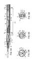
- FIG. 1Ais a longitudinal side section showing a distal end portion in a living tissue ligating apparatus according to a first embodiment of the present invention
- FIG. 1Bis a sectional view taken along the line A—A of FIG. 1A ;
- FIG. 1Cis a sectional view taken along the line B—B of FIG. 1A ;
- FIG. 1Dis a sectional view taken along the line C—C of FIG. 1A ;
- FIG. 1Eis a sectional view taken along the line D—D of FIG. 1C ;
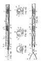
- FIG. 2Ais a longitudinal side section showing a distal end portion in the ligating apparatus illustrating the working of the present embodiment
- FIG. 2Bis a sectional view taken along the line E—E of FIG. 2A ;
- FIG. 2Cis a sectional view taken along the line F—F of FIG. 2A ;
- FIG. 2Dis a sectional view taken along the line G—G of FIG. 2A ;
- FIG. 2Eis a sectional view taken along the line H—H of FIG. 2C ;
- FIG. 3Ais a longitudinal side section showing a distal end portion in the ligating apparatus according to the working of the present embodiment
- FIG. 3Bis a sectional view taken along the line I—I of FIG. 3A ;
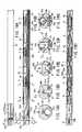
- FIG. 4is a longitudinal side section showing a distal end portion in the ligating apparatus according to working of the present embodiment
- FIG. 5Ais a longitudinal side section showing a distal end portion in the ligating apparatus according to working of the present embodiment
- FIG. 5Bis a sectional view taken along the line J—J of FIG. 5A ;
- FIG. 6is a longitudinal side section showing a distal end portion in the ligating apparatus according to working of the present embodiment
- FIG. 7Ais a longitudinal side section of a distal end portion in the ligating apparatus according to working of the present embodiment
- FIG. 7Bis a sectional view taken along the line K—K of FIG. 7A ;
- FIG. 8is a longitudinal side section showing a state in which clips are retained in living tissues according to the working of the present invention.
- FIG. 9is a longitudinal side section showing a state of connection between the clips each and the manipulating wire according to the present embodiment.
- FIG. 10is a side view showing a manipulating wire according to the present embodiment.
- FIG. 11is a perspective view showing a clip tightening ring according to the present embodiment.
- FIG. 12Ais a longitudinal side view showing a distal end portion in a living tissue ligating apparatus according to a second embodiment of the present invention.
- FIG. 12Bis a sectional view taken along the line L—L of FIG. 12A ;
- FIG. 12Cis a sectional view taken along the line M—M of FIG. 12A ;
- FIG. 12Dis a sectional view taken along the line N—N of FIG. 12A ;
- FIG. 13Ais a longitudinal side section showing a distal end portion in a ligating apparatus according to working of a third embodiment of the present invention.
- FIG. 13Bis a sectional view taken along the line O—O of FIG. 13A ;
- FIG. 13Cis a sectional view taken along the line P—P of FIG. 13A ;
- FIG. 13Dis a sectional view taken along the line Q—Q of FIG. 13A ;
- FIG. 13Eis a sectional view taken along the line R—R of FIG. 13C ;
- FIG. 14Ais a longitudinal side section showing a distal end portion in the ligating apparatus according to working of the present embodiment
- FIG. 14Bis a sectional view taken along the line S—S of FIG. 14A ;
- FIG. 14Cis a sectional view taken along the line T—T of FIG. 14A ;
- FIG. 14Dis a sectional view taken along the line U—U of FIG. 14A ;
- FIG. 14Eis a sectional view taken along the line V—V of FIG. 14C ;
- FIG. 15is a longitudinal side section showing a distal end portion in the ligating apparatus according to the present embodiment.
- FIG. 16is a longitudinal side section showing a distal end portion in the ligating apparatus according to the present embodiment
- FIG. 17is a longitudinal side section showing a distal end portion in the ligating apparatus according to the present embodiment.
- FIG. 18Ais a plan view showing a distal end portion in a ligating apparatus according to a fourth embodiment of the present invention.
- FIG. 18Bis a sectional side section of the same.
- FIG. 18Cis a sectional view taken along the line “a—a” of FIG. 18B ;
- FIG. 18Dis a sectional view taken along the line “b—b” of FIG. 18B ;
- FIG. 18Eis a sectional view taken along the line “c—c” of FIG. 18B ;
- FIG. 18Fis a sectional view taken along the line “d—d” of FIG. 18B ;
- FIG. 18Gis a sectional view taken along the line “e—e” of FIG. 18B ;
- FIG. 18His a sectional view taken along the line “f—f” of FIG. 18F ;
- FIG. 19is a longitudinal side section showing a distal end portion in the ligating apparatus according to working of the present invention.
- FIG. 20is a longitudinal side section showing a distal end portion in the ligating apparatus according to working of the present invention.
- FIG. 21a longitudinal side section showing a distal end portion in the ligating apparatus according to working of the present invention
- FIG. 22Ais a plan view showing a distal end portion in the ligating apparatus according to working of the present invention.
- FIG. 22Bis a longitudinal side section of the same
- FIG. 22Cis a sectional view taken along the line “g—g” of FIG. 22B ;
- FIG. 22Dis a sectional view taken along the line “h—h” of FIG. 22B ;
- FIG. 22Eis a sectional view taken along the line “i—i” of FIG. 22B ;
- FIG. 22Fis a sectional view taken along the line “j—j” of FIG. 22B ;
- FIG. 22Gis a sectional view taken along the line “k—k” of FIG. 22B ;
- FIG. 22His a sectional view taken along the line “m—m” of FIG. 22F ;
- FIG. 23is a longitudinal side section showing a distal end portion in the ligating apparatus according to working of the present invention.
- FIG. 24is a longitudinal side section showing a distal end portion in the ligating apparatus according to working of the present invention.
- FIG. 25is a longitudinal side section showing a distal end portion in the ligating apparatus according to working of the present invention.
- FIG. 1A to FIG. 11show a first embodiment of the present invention.
- an introducing tube 1has flexibility such that the tube can be inserted into an endoscope channel.
- a distal end tip 2is provided at a distal end portion of this introducing tube 1 .
- the introducing tube 1is provided as a tune sheath that consists of a polymeric resin described later, for example, and a first tube channel 1 a and a second tube channel 1 b are provided in parallel to each other over an axial direction.
- the first tube channel 1 ais formed in a substantially oval shape on its transverse cross section, and has a large inner diameter so that a clip and a clip tightening ring described later can be inserted.
- the second tube channel 1 bis also formed in a substantially oval shape on its transverse cross section, and has a small inner diameter so that a manipulating wire described later can be inserted.
- the first tube channel 1 a and second tube channel 1 bcommunicate with a communication channel 1 c by being superimposed at a part of its sectional shape. Further, a distal end opening of the second tube channel 1 b is closed by a proximal end portion 2 a of the distal end tip 2 .
- This distal end tip 2is fixed to the distal end portion of the introducing tube 1 by means of welding, adhesive, or press-fit.
- a compression member 3is movably inserted into the first tube channel 1 a of the introducing tube 1 .
- a manipulating wire 13is inserted into the compression member 3 .
- Manipulating wires 6 and 9are movably inserted into the second tube channel 1 b .
- Clips 4 and 7that are freely protruded and recessed from a distal end portion of the introducing tube 1 are removably connected to the distal end portion of the manipulating wires 6 and 9 each.
- the clip 10that is freely protruded and recessed from the distal end portion of the introducing tube 1 is removably connected to the distal end portion of the manipulating wire 13 via a connecting plate 12 .
- the introducing tube 1is provided as a tube sheath made of a polymeric resin (such as synthetic polymeric polyamide, high density/low density polyethylene, polyester, polytetrafluoro ethylene, tetrafluoro ethylene-perfluoroalkylivinyl ether copolymer, tetrafluoro ethylene-hexafluoro propylene copolymer).
- a polymeric resinsuch as synthetic polymeric polyamide, high density/low density polyethylene, polyester, polytetrafluoro ethylene, tetrafluoro ethylene-perfluoroalkylivinyl ether copolymer, tetrafluoro ethylene-hexafluoro propylene copolymer.
- the internal and external faces of the sheathhave slipping properties, thus making it easy to insert the tube into, and remove it from, an endoscope channel, protrude the clips 4 , 7 , and 10 , and insert the manipulating wires 6 , 9 , and
- the introducing tube 1is provided as a double tube having an inner layer and an outer layer at its external wall portion, and may be a tube sheath embedded while a reinforce member is interposed between the double tubes.
- the inner layer and outer layerare formed of the above polymeric resin.
- the reinforce memberis formed of a cylindrically-shaped blade knitted with a thin metal line in a lattice shape, for example. In this manner, even when a force of compressing a sheath against the distal end portion and proximal end portion of the sheath, this sheath has its excellent compression resistance as compared with a tube sheath in which no reinforce member is embedded, and the sheath is free of being broken.
- the introducing tube 1has its outer diameter that the tube can be inserted into the endoscope channel.
- the thickness of the sheathis determined depending on the rigidity of its element material.
- the polymeric resin based tubeis about 0.3 mm to 0.8 mm in thickness.
- the distal end tip 2is provided as a metallic short tube (such as a stainless tube), and a blade provided at the clip tightening ring described later is dimensionally set so that the blade can be engaged with the tip.
- the most distal end of the distal end tip 2is 1.5 mm to 3.3 mm in outer diameter, and the distal end top 2 is about 1.0 mm to 2.2 mm in inner diameter.
- the compression member 3has flexibility such that the member can be inserted into the first tube channel 1 a of the introducing tube 1 .
- This compression memberis disposed backwardly of the clip tightening ring 11 described later, the ring being mounted in the introducing tube 1 , and is provided to protrude the clips 4 , 7 , and 10 from the introducing tube 1 .
- the compression member 3may be a coil sheath with its irregular internal and external faces on which a metallic wire (such as stainless wire) with its round shaped sectional face is closely wound or a rectangular coil sheath with its flat internal and external faces obtained after the wire cross section is made rectangular by breaking a metallic wire (such as stainless wire) whose sectional face is rounded, for example.
- a coil sheath with its large inner diametercan be provided as compared with a round shaped coil even if an element wire diameter of the same diameter is employed. This makes it easier to protrude the clips 4 , 7 , and 10 , and insert a manipulating wire 13 .
- This compression member 3is moved to the distal end side relevant to the introducing tube 1 , thereby making it possible to protrude the clips 4 , 7 , and 10 and the clip tightening rings 5 , 8 , and 11 from the introducing tube 1 .
- the compression member 3may be a tube sheath made of a polymeric resin (such as synthetic polymeric polyamide, high density/low density polyethylene, polyester, polytetrafluoro ethylene, tetrafluoro ethylene-perfluoroalkylivinyl ether copolymer, tetrafluoro ethylene-hexafluoro propylene copolymer).
- a polymeric resinsuch as synthetic polymeric polyamide, high density/low density polyethylene, polyester, polytetrafluoro ethylene, tetrafluoro ethylene-perfluoroalkylivinyl ether copolymer, tetrafluoro ethylene-hexafluoro propylene copolymer.
- the compression member 3is provided as a double tube having an inner layer and an outer layer at its wall portion, and may be a tube sheath embedded while a reinforce member is interposed between the double tubes.
- the inner layer and outer layerare formed of the above polymeric resin.
- the reinforce memberis formed of a cylindrically shaped blade knitted with a thin metal line in a lattice shape, for example. In this manner, even when a force of compressing a sheath against the distal end portion and proximal end portion of the sheath, this sheath has its excellent compression resistance as compared with a tube sheath in which no reinforce member is embedded, and the sheath is free of being broken.
- the compression member 3has an outer diameter such that the member can be inserted into the first tube channel 1 a of the introducing tube 1 and an inner diameter such that the manipulating wire 13 can be inserted.
- the outer diametershould be defined to be 3 mm or less in diameter, and the inter diameter should be as large as possible.
- the compression memberrequires thickness such that the protrusion force quantity can be reliably transmitted, and, even if a force is applied to be protruded to the clips 4 , 7 , and 10 , no breakage occurs.
- the clips 4 , 7 , and 10are identical to each other in structure. A description of the clip 4 will be given here.
- a metallic thin band plateis returned at its center portion, and its returned portion is defined as a proximal end portion 4 a .
- both arm sections 4 b and 4 b ′ extending from this proximal end portion 4 aare returned in an expanding/opening direction.
- the distal end rim portions of the arm sections 4 b and 4 b ′each are returned so as to face to each other, and are defined as pinch sections 4 c and 4 c ′.
- One of the distal ends of the pinch sections 4 c and 4 c ′is formed to be protruded, and the other is formed to be recessed so as to easily pinch living tissues. Then, the opening/expanding properties are imparted to the arm sections 4 b and 4 b ′ so as to open the pinch section 4 c.
- a thin band plate of the clip 4is made of stainless having resilience, whereby the clip is made rigid and is capable of reliably pinching living tissues.
- an ultra-elastic alloysuch as nickel-titanium alloy
- the expanding/opening propertiesare imparted to the arm sections 4 b and 4 b ′, whereby the arm sections 4 b and 4 b ′ open more reliably than when they are protruded from the sheath.
- the band plate of the clip 4is 0.15 mm to 0.3 mm in thickness; the pinch sections 4 c and 4 c ′ are 0.5 mm to 1.2 mm in plate width; and the arm sections 4 b and 4 b ′ are 0.5 mm to 1.5 mm in plate width.
- the proximal end portion 4 ais 0.3 mm to 0.5 mm in plate width.
- the manipulating wire 6is composed of a loop wire 6 a and a proximal end wire 6 b .
- the loop wire 6 ais molded to be closed at a distal end of the proximal wire 6 b composed of a metallic twisted wire. Only one twisted wire of the proximal wire 6 b forms the loop wire 6 a .
- the core wiremay be a twisted wire or a single wire.
- the loop wire 6 a and proximal end wire 6 bare bonded with each other via a metallic connecting pipe 6 c by means of welding or adhesive.
- the manipulating wires 6 , 9 and 13are, for example, stainless twisted wires. Such twisted wire is more flexible than the single wire, and flexibility of the introducing wire 1 itself is not degraded.
- the manipulating wires 6 , 9 , and 13may be coated with a polymeric resin 13 a with its improved slipping properties such as high density/low density polyethylene or polytetrafluoro ethylene, for example.
- the optimal thickness of the coatis about 0.05 mm to 0.1 mm.
- emboss processing of 0.01 mm to 0.45 mm on the wire surfacesin order to improve the slipping properties of the manipulating wire 6 , 9 and 13 . Accordingly, the frictional resistance with an internal face of the introducing tube 1 decreases, and the traction force quantity can be transmitted up to a distal end of the introducing tube 1 without any loss. In this manner, ligating manipulation can be carried out with smaller force.
- a force of 1 kg to 5 kgis applied to the loop wire 6 a when the clip 4 is ligated. At this time, it is required to define dimensions such that the loop wire 4 a breaks.
- the proximal end wire 4 bis 0.3 mm to 0.8 mm in outer diameter, and the loop wire 4 a is about 0.1 mm to 0.2 mm in diameter.
- the thus-constructed manipulating wires 6 and 9each have a bent portion 6 d at which a wire at the proximal end side of the connecting pipe 6 c is bent in a substantially crank shape.
- the manipulating wires 6 and 9 inserted into a second tube channel 1 badvance into the first tube channel 1 a when the bent portion 6 d passes through a communicating channel 1 c .
- the connecting pipe 6 c and loop wire 6 aare connected to the clips 4 and 7 in the first tube channel 1 a.
- the manipulating wire 13is returned in close proximity to the distal end of the introducing tube.
- the distal end of the wireis connected to the proximal end portion of the connecting plate 12 , and is inserted into the proximal end portion of the introducing tube.
- the distal end portion of this connecting plate 12is connected to the proximal end portion 4 a of the clip 10 via a claw 12 a bent in a J shape.
- the clip tightening rings 5 , 8 , and 11are identical to each other in structure. A description of the clip tightening clip 5 will be given here.
- the clipis molded of a resin or metal having rigidity and elasticity.
- Two blades 5 a and 5 b that are elastically deformed and freely protruded and recessed in a circumferential directionare provided at the outer periphery of the clip tightening ring 5 .
- the number of blades 5 a and 5 bis not limited to two, and may be three or four.
- the blades 5 a and 5 bare inclined at their tip end side. These blades can be protruded from the introducing tube 1 and distal end tip 2 smoothly and without any resistance.
- the clip tightening ring 5is mounted on the arms 4 b and 4 b ′ of the clip 4 , thereby closing the arm sections 4 a and 4 b ′.
- This ringis formed in a substantially tubular shape.
- the clip 4 and manipulating wire 6are engaged with each other by hooking the loop wire 6 a on the proximal end portion 4 a of the clip 4 . Even if the clip 4 is extruded by the manipulating wire 6 , a polymeric material 14 such as silicone is engaged in the clip tightening ring, as shown in FIG. 1E , so that the engagement between the clip 4 and manipulating wire 6 can be maintained, and the clip 4 and clip tightening ring 5 can be temporarily fixed.
- the blades 5 a and 5 b of the clip tightening ring 5may be mounted in the first tube channel 1 a of the introducing tube 1 in a folded state. However, the blades 5 a and 5 b are mounted on the introducing tube 1 in a protruded state, whereby the elasticity of the blades 5 a and 5 b can be maintained over a longer period of time. In addition, the contact resistance between an internal face of the introducing tube 1 and the blades 5 a and 5 b each decreases, thus making it possible to decrease the force quantity when the clip 4 is moved in the introducing tube 1 .
- the clip tightening ring 5is injection-molded of a resin having rigidity and elasticity (such as polybutytelephthalate, polyamide, polyphenyl amide, liquid crystal polymer, polyether ketone, or polyphthalic amide).
- a resin having rigidity and elasticitysuch as polybutytelephthalate, polyamide, polyphenyl amide, liquid crystal polymer, polyether ketone, or polyphthalic amide.
- the ringis molded of an elastic metal (stainless or ultra-elastic alloy such as nickel titanium alloy), for example, by means of injection-molding, cutting processing, or plastic processing and the like.
- a tubular portion of the clip tightening ring 5is 0.6 mm to 1.3 mm in inner diameter and about 1.0 mm to 2.1 mm in outer diameter.
- the most outer diameter portion when the blades 5 a and 5 b are protrudedis defined to be 1 mm or more considering the engagement with the distal end tip 2 .
- the introducing tube 1 of the ligating apparatusis introduced into a body cavity via the channel of the endoscope inserted into the body cavity. Then, a distal end portion of the introducing tube 1 is located in close proximity to a clipping target tissue, for example, a gastric mucous membrane tissue.
- the compression member 3is extruded in a distal end direction of the introducing tube 1 , whereby a compression force is transmitted in order to the clip tightening ring 11 , clip 10 , clip tightening ring 8 , clip 7 , and clip tightening ring 5 . Then, the most frontal clip 4 and clip tightening ring 5 are protruded from the distal end portion of the distal end tip 2 .
- the blades 5 a and 5 b of the clip tightening ring 5are folded when they pass through the inside of the distal end tip 2 . When they pass through the distal end tip 2 , the blades 5 a and 5 b are protruded again. In this manner, the clip tightening ring 5 is prevented from entering the inside of the distal end tip 2 again.
- the blades 5 a and 5 b of the clip tightening ring 5are engaged with an end face of the distal end tip 2 .
- an oval portion of the proximal end portion 4 a of the clip 4is retracted into the clip tightening ting 5 .
- the oval portionis greater than the inner diameter of the clip tightening ring 5 , and the oval portion is crushed by the clip tightening ring S. Then, the arm sections 4 b and 4 b ′ expand and open significantly to the outside.
- the clip 4is guided so as to pinch a target living tissue.
- the manipulating wire 6is further retracted, whereby the arm sections 4 b and 4 b ′ of the clip 4 are retracted into the clip tightening ring 5 , and then, the pinch sections 4 c and 4 c ′ of the clip 4 are closed.
- the living tissueis reliably pinched between the arm sections 4 b and 4 b ′ of the clip 4
- the loop wire 6 ais broken, and the clip 4 and manipulating wire 6 are disengaged from each other. In this manner, as shown in FIG. 8 , the clip 4 can be retained in a body cavity while a living tissue X is pinched.
- the manipulating wire 6is retracted into the frontal side, and the compression member 3 is extruded in a distal end direction of the introducing tube 1 again.
- a compression forceis transmitted in order to the clip tightening ring 11 , clip 10 , and clip tightening ring 8 , and a second clip 7 and a clip tightening ring 8 are protruded from the distal end portion of the distal end tip 2 .
- the clip 7is guided so as to pinch a target living tissue.
- the manipulating wire 9is further retracted, whereby the arm sections 4 b and 4 b ′ of the clip 7 are retracted into the clip tightening ring 8 , and the pinch sections 4 c and 4 c ′ of the clip 7 are closed. While a living tissue is reliably pinched between the arm sections 4 b and 4 b ′ of the clip 7 , when the manipulating wire 9 is further retracted, the loop wire 6 a is broken. Then, the clip 7 and manipulating wire 9 are disengaged from each other, and the clip 7 can be retained in a body cavity while the living tissue X is pinched.
- the manipulating wire 9is introduced into the frontal side, and the compression member 3 is extruded in a distal end direction of the introducing tube 1 again.
- a compression forceis transmitted to a clip tightening ring 11 , and a third clip 10 and the clip tightening ring 11 are protruded from the distal end portion of the distal end tip 2 .
- the clip 10is guided so as to pinch a target living tissue.
- the manipulating wire 13is further retracted, whereby the arm sections 4 b and 4 b ′ of the clip 10 are retracted into the clip tightening ring 11 , and the pinch sections 4 c and 4 c ′ of the clip 10 are closed.
- a claw 12 a bent in a J letter shapeextends linearly; the proximal end portion 4 a and connecting plate 12 of the clip 10 are separated from each other; the clip 10 and manipulating wire 13 are disengaged with each other; and the clip 10 can be retained in a body cavity while the living tissue X is pinched, as shown in FIG. 7 A and FIG. 7 B.
- a plurality of clips mounted in the introducing tubecan be retained merely inserting the ligating apparatus in the body cavity one time. This makes it unnecessary to do a complicated work that the ligating apparatus is retracted to the outside of the body cavity every time one clip is retained in the body cavity, and the clip is mounted again and inserted into the body cavity again. In this manner, a surgical operation time can be reduced, and thus, a patient's pain can be reduced.
- the manipulating wireis inserted into a tube channel other than that in which clips are arranged.
- the clipscan be retained speedily, easily, and reliably in the body cavity one by one without interference between the clips each and the manipulating wire.
- FIG. 12A to FIG. 12Dshow a second embodiment of the present invention.
- Like constituent elements shown in the first embodimentare designated by like reference numerals. A duplicate description is omitted here.
- An introducing tube 21 of the present embodimentis formed of a multi-lumen tube in which a first tube channel 21 a and a second tube channel 21 b are partitioned from each other by a bulkhead 21 c .
- a communicating channel 21 dconsisting of a slit that communicates with the first tube channel 21 a and the second tube channel 21 b is provided at the bulkhead 21 c in close proximity to a distal end portion of the introducing tube 21 .
- 21 Aindicates a slit length.
- a pin 22 a protruded at the proximal end sideis provided at the distal end tip 22 .
- This pin 22 ais press-fitted to the second tube channel 21 b to close a distal end opening of the second tube channel 21 b .
- FIG. 13A to FIG. 17show a third embodiment of the present invention.
- Like constituent elements shown in the first and second embodimentsare designated by like reference numerals. A duplicate description is omitted here.
- an introducing tube 30has flexibility such that the tube can be inserted into the endoscope channel.
- a distal end tip 31is provided at a distal end portion of this introducing tube 30 .
- the introducing tube 30is composed of a multi-lumen tube in which a first tube channel 30 a whose transverse sectional face is formed in a substantially oval shape and a second tube channel 30 b formed in a circular shape are partitioned from each other by a bulkhead 30 c .
- a distal end tip 31is provided at a distal end portion of the introducing tube 30 .
- the bulkhead 30 c of the introducing tube 30is cut out at the inside of the distal end tip 31 , and the first tube channel 30 a and the second tube channel 30 b communicate with each other.
- an engaging stepped portion 32 engaged with the clip tightening rings 5 , 8 , and 11is provided to be deflected to the second tube channel 30 b side.
- a holding element 30having a guide groove 33 a for slidably guiding a manipulating wire described later is fixed to the distal end.
- One manipulating wire 34is movably inserted into the first tube channel 30 a and the second tube channel 30 b .
- This manipulating wire 34is returned to form a loop section at the inside of the distal end tip 31 , and the loop section is guided into a guide groove 33 a of the holding element 33 .
- an advancing side 34 a at one end side of the manipulating wire 34is inserted into the first tube channel 30 a
- a retracting side 34 b at the other endis inserted into the second tube channel 30 b.
- this manipulating wire 34has slipping properties and flexibility.
- this wireis formed of a polymeric fiber such as polyparaphenylene benzobisoxazole, polyethylene, polyester, polypropylene, polyamide, or liquid crystal polymer.
- this manipulating wire 34At an intermediate portion of this manipulating wire 34 , three loop shaped connecting wires 35 are securely fixed at the connecting portion 36 with predetermined intervals by means of fusion welding, adhesive, and another yarn binding. Then, the clips 4 , 7 , and 10 each similar to those according to the first embodiment are connected respectively to the connecting wire 35 .
- this connecting wire 35has slipping properties and flexibility.
- this wireis formed of a polymeric fiber such as polyparaphenylene benzobisoxazole, polyethylene, polyester, polypropylene, polyamide, or liquid crystal polymer. Then, the connecting wire can move freely on the manipulating wire 34 irrespective of advancement or retraction of the manipulating wire 34 .
- the introducing tube 30 of the ligating apparatusis introduced into a body cavity via the endoscope channel inserted into the body cavity. Then, a distal end portion of the introducing tube 30 is located in close proximity of a clipping target tissue, for example, a gastric mucous membrane tissue.
- a retracting side 34 b of the manipulating wire 34 inserted into the second tube channel 30 bis retracted to the frontal side of the introducing tube 30 , the manipulating wire 34 is returned to form a loop section at a portion of the holding element 33 . Then, an advancing side 34 a of the manipulating wire 34 advances to the distal end side of the introducing tube 30 . Therefore, as shown in FIG. 14A to FIG. 14E , the most frontal clip 4 and clip tightening ring 5 are protruded from the distal end portion of the distal end tip 31 .
- the clip 4is guided so as to pinch a target living tissue.
- the retracting side 34 b of the manipulating wire 34is further retracted, whereby the arm sections 4 b and 4 b ′ of the clip 4 are retracted into the clip tightening ring 5 , and the pinch sections 4 c and 4 c ′ of the clip 4 are closed.
- a living tissueis reliably pinched between the arm sections 4 b and 4 b ′ of the clip 4
- the retracting side 34 b of the manipulating wire 34is further retracted, the connecting wire 35 is broken, and the clip 4 and manipulating wire 34 are disengaged from each other, as shown in FIG. 15 . In this manner, the clip 4 can be retained in a body cavity while the living tissue is pinched.
- the retracting side 34 b of the manipulating wire 34is retracted to the frontal side, and the second clip 7 and clip tightening ring 8 are protruded from the distal end tip 31 .
- the pinch sections 4 c and 4 c ′ of the clip 7are close to the target tissue
- a rear end of the clip tightening ring 8is engaged with the engaging stepped portion 32 .
- the retracting side 34 b of the manipulating wire 34is further retracted, the oval portion of the proximal end portion 4 a of the clip 7 is retracted into the clip tightening ring 8 .
- the arm sections 4 b and 4 b ′expand/open significantly to the outside.
- the clip 7is guided so as to pinch a target living tissue.
- the retracting side 34 b of the manipulating wire 34is further retracted, whereby the arm sections 4 b and 4 b ′ of the clip 7 are retracted into the clip tightening ring 8 , and the pinch sections 4 c and 4 c ′ of the clip 7 are closed.
- the living tissueis reliably pinched between the arm sections 4 b and 4 b ′ of the clip 7
- the connecting wire 35is broken. Then, the clip 7 and wire 34 are disengaged from each other, and the clip 7 can be retained in a body cavity while the living tissue is pinched.
- the retracting side 34 b of the manipulating wire 34is retracted to the frontal side, and the third clip 10 and clip tightening ring 11 are protruded from the distal end tip 31 .
- the pinch sections 4 c and 4 c ′ of the clip 10are close to a target tissue, when the retracting side 34 b of the manipulating wire 34 is retracted, a rear end of the clip tightening ring 11 is engaged with the engaging stepped portion 32 .
- the clip 10is guided so as to pinch a target living tissue.
- the retracting side 34 b of the manipulating wire 34is further retracted, whereby the arm sections 4 b and 4 b ′ of the clip 10 are retracted into the clip tightening ring 11 , and the pinch sections 4 c and 4 c ′ of the clip 10 are closed.
- the living tissueis reliably pinched between the arm sections 4 b and 4 b ′ of the clip 10
- the connecting wire 35is broken.
- the clip 7 and wire 34are disengaged from each other, and the clip 7 can be retained in a body cavity while the living tissue is pinched.
- a plurality of clips mounted in the introducing tubecan be retained in a body cavity merely by inserting the ligating apparatus into the body cavity one time.
- a compression memberis eliminated, and one end of the manipulating wire is merely retracted, whereby the clips can be continuously protruded and ligated. In this manner, a construction and operation can be simplified.
- the introducing tubecan be reduced in diameter.
- FIG. 18A to FIG. 25each show a fourth embodiment of the present invention.
- Like constituent elements shown in the first and third embodimentsare designated by like reference numerals. A duplicate description is omitted here.
- an introducing tube 50has flexibility such that the tube can be inserted into the endoscope channel.
- a holding element 51is provided at a distal end portion of this introducing tube 50 .
- the introducing tube 50is composed of a multi-lumen tube in which a first tube channel 50 a whose transverse cross section is shaped in a large diameter circle and a second tube channel 50 b shaped in a small diameter circle are partitioned by a bulkhead 50 c .
- a rectangular opening portion 50 dis provided along an axial direction of the introducing tube 50 . This opening portion communicates with the first tube channel 50 a.
- an inclined face 51 a with its upward gradient toward the distal end of the introducing tube 50is provided in opposite to the opening portion 50 d .
- a flat face 51 bis continuously provided from the top portion of this inclined face 51 a .
- a grooveis provided partly of this flat face 51 b .
- a fiber yarn 51 fis embedded in order to reliably fix the holding element 51 to the distal end of the introducing tube 50 .
- This fiber yarn 51 fis fixed to be reliably wound along the peripheral direction. Adhesive is applied to a portion around which the fiber yarn 51 f is wound, whereby the fiber yarn can be fixed more reliably.
- an arc shaped portion 51 cis provided continuously from the flat face 51 b.
- a longitudinally-elongated wire channel 51 d that communicates with the second tube channel 50 b and inserts the manipulating wire 54is provided at the low portion of the holding element 51 .
- An circularly-opening engaging stepped portion 51 e engaged with the clip tightening rings 5 , 8 , and 11is provided at the front portion of this wire channel 51 d.
- One manipulating wire 54is movably inserted into the first tube channel 50 a and the second tube channel 50 b .
- This manipulating wire 54is returned to form a loop section at the arc shaped portion 51 c of the holding element 51 , and the loop section is guided to the wire channel 51 d of the holding element 51 .
- an advancing side 54 a at one end side of the manipulating wire 54is inserted into the first tube channel 50 a
- a retracting side 54 b at the other end sideis inserted into the second tube channel 50 b.
- the wireis formed of a polymeric fiber such as polyparaphenylene benzobisoxazole, polyethylene, polyester, polypropylene, polyamide, or liquid crystal polymer, for example.
- this manipulating wire 54At an intermediate portion of this manipulating wire 54 , three loop shaped connecting wires 55 are securely fixed at the connecting portion 56 with predetermined intervals by means of fusion welding, adhesive, and another yarn binding. Then, the clips 4 , 7 , and 10 each similar to those according to the first and third embodiments are connected respectively to the connecting wire 55 .
- this connecting wire 55has slipping properties and flexibility.
- this wireis formed of a polymeric fiber such as polyparaphenylene benzobisoxazole, polyethylene, polyester, polypropylene, polyamide, or liquid crystal polymer. Then, the connecting wire can move freely on the manipulating wire 54 irrespective of advancement or retraction of the manipulating wire 54 .
- a reinforce wire 57is provided as a reinforce wire such as steel wire inserted into a lumen 57 a in order to improve rigidity of the introducing tube 50 and strength of connection between the introducing tube 50 and holding element 51 . This wire is disposed in pair while the second tube channel 5 b is sandwiched.
- the introducing tube 50 of the ligating apparatusis introduced into a body cavity via the channel of the endoscope inserted into the body cavity. Then, a distal end portion of the introducing tube 50 is located in close proximity to a clipping target tissue, for example, a gastric mucous membrane tissue.
- a clipping target tissuefor example, a gastric mucous membrane tissue.
- the clip tightening ring 5when the clip tightening ring 5 is located on the top face of the flat face 51 b of the holding element 51 , the clip 4 and clip tightening ring 5 are substantially parallel to the introducing tube 50 .
- the connecting portion 56passes through the arc shaped portion 51 c .
- the clip tightening ring 5drops in an engaging stepped portion 51 e . In this manner, the clip tightening ring 5 is prevented from entering the introducing tube 50 again.
- the clip 4is guided so as to pinch a target living tissue.
- the retracting side 54 b of the manipulating wire 54is further retracted, whereby the arm sections 4 b and 4 b ′ of the clip 4 are retracted into the clip tightening ring 5 , and then, the pinch sections 4 c and 4 c ′ of the clip 4 are closed.
- the living tissueis reliably pinched between the arm sections 4 b and 4 b ′ of the clip 4
- the connecting wire 55is broken, and the clip 4 and manipulating wire 54 are disengaged from each other, as shown in FIG. 23 . In this manner, the clip 4 can be retained in a body cavity while a living tissue is pinched.
- the retracting side 54 b of the manipulating wire 54is retracted to the frontal side, the second clip 7 and clip tightening ring 8 are protruded from a distal end of the introducing tube 50 . Then, in the same manner as that described previously, while the pinch sections 4 c and 4 c ′ of the clip 7 are close to a target tissue, when the retracting side 54 b of the manipulating wire 54 is retracted, a rear end of the clip tightening ring 8 is engaged with the engaging stepped portion 51 e .
- the clip 7is guided so as to pinch a target living tissue.
- the retracting side 54 b of the manipulating wire 54is further retracted, whereby the arm sections 4 b and 4 b ′ of the clip 7 are retracted into the clip tightening ring 8 , the pinch sections 4 c and 4 c ′ of the clip 7 are closed.
- the living tissueis reliably pinched between the arm sections 4 b and 4 b ′ of the clip 7
- the connecting wire 55is broken.
- the clip 7 and manipulating wire 54are disengaged from each other, and the clip 7 can be retained in a body cavity while the living tissue is pinched.
- the retracting side 54 b of the manipulating wire 54is retracted to the frontal side, the third clip 10 and the clip tightening ring 11 are protruded from the distal end of the introducing tube 50 .
- the pinch sections 4 c and 4 c ′ of the clip 10are close to a target tissue
- a rear end of the clip tightening ring 11is engaged with an engaging stepped portion 51 e .
- the retracting side 54 b of the manipulating wire 54is further retracted, the oval portion of the proximal end portion 4 a of the clip 10 is retracted into the clip tightening ring 11 .
- the arm sections 4 b and 4 b ′expand/open significantly to the outside.
- the clip 10is guided so as to pinch a target living tissue.
- the retracting side 54 b of the manipulating wire 54is further retracted, whereby the arm sections 4 b and 4 b ′ of the clip 10 are retracted into the clip tightening ring 11 , and the pinch sections 4 c and 4 c ′ of the clip 10 are closed.
- the living tissueis reliably pinched between the arm sections 4 b and 4 b ′ of the clip 10
- the connecting wire 55is broken.
- the clip 7 and manipulating wire 54are disengaged from each other, and the clip 7 can be retained in a body cavity while the living tissue is pinched.
- a plurality of clips mounted in an introducing tubecan be retained in a body cavity merely by inserting the ligating apparatus one time. This makes it unnecessary to do a work that the clipping apparatus is retracted to the outside of the body cavity every time one clip is retained in the body cavity, and clips are mounted again and inserted into the body cavity again. Therefore, the clips can be retained in a body cavity one by one speedily, easily, and reliably. In this manner, a surgical operation time can be reduced, and a patient's pain can be reduced.
- the curvature radius of the return portion of the manipulating wireis increased by a holding element provided at the distal end portion of the introducing tube, whereby the traction force quantity of the manipulating wire can be reduced.
- eachalthough three clips have been mounted in the introducing tube, four or more clips may be mounted.
Landscapes
- Health & Medical Sciences (AREA)
- Surgery (AREA)
- Life Sciences & Earth Sciences (AREA)
- Heart & Thoracic Surgery (AREA)
- Nuclear Medicine, Radiotherapy & Molecular Imaging (AREA)
- Vascular Medicine (AREA)
- Engineering & Computer Science (AREA)
- Biomedical Technology (AREA)
- Reproductive Health (AREA)
- Medical Informatics (AREA)
- Molecular Biology (AREA)
- Animal Behavior & Ethology (AREA)
- General Health & Medical Sciences (AREA)
- Public Health (AREA)
- Veterinary Medicine (AREA)
- Surgical Instruments (AREA)
Abstract
Description
This application is based upon and claims the benefit of priority from the prior Japanese Patent Application No. 2001-088382, filed Mar. 26, 2001, the entire contents of which are incorporated herein by reference.
1. Field of the Invention
The present invention relates to a living tissue ligating apparatus for ligating living tissues by inserting the apparatus into a living body cavity in a transendoscopic manner.
2. Description of the Related Art
Conventionally, it has been well known that apparatuses for clipping living tissues are disclosed in Jpn. UM. Appln. KOKAI Publication No. 2-6011 and Jpn. Pat. Appln. KOKAI Publication No. 63-267345. In Jpn. UM. Appln. KOKAI Publication No. 2-6011, a clip and a manipulating wire is engaged with each other via a hook provided at a distal end portion of the manipulating wire and a connecting member provided at a distal end of the hook, the connecting member having a hook.
In addition, in Jpn. Pat. Appln. KOKAI Publication No. 63-267345, a plurality of clips are incorporated in an introducing tube; the clips and manipulating member are connected with each other by a substance with its low melting point; and the substance with its low melting point is fused while it is inserted into a body cavity so as to continuously carry out a clip ligating work.
However, in the clipping apparatus disclosed in Jpn. UM. Appln. KOKAI Publication No. 2-6011, only one clip can be mounted on a distal end of the introducing tube. Thus, only one clip can be used each time it is inserted into a body cavity through a forceps channel of an endoscope. Thus, when a plurality of living tissues in the internal living body cavity are clipped, it has been necessary to do a work that the clipping apparatus is pulled out from the forceps channel of the endoscope every time, and the clips are mounted and inserted into the forceps channel again. Therefore, there has been a disadvantage that complicated and very time consuming work is required.
In addition, there are many disease cases requiring high emergency when a clip is applied to a bleeding site. In such disease cases, such a complicated and time consuming work has been very problematic.
In order to these problems in Jpn. Pat. Appln. KOKAI Publication No. 63-267345, there is disclosed a clipping apparatus capable of continuously carrying out ligation by inserting it into the forceps channel only one time. In the clipping apparatus disclosed, a plurality of clips are connected respectively with each other by a substance with its low melting point. Then, a temperature is controlled by a heating element provided at a tip end of a sheath of the clipping apparatus, whereby ligation is continuously carried out. That is, a structure is provided such that the heating element is heated up to a temperature at which the substance with its low temperature is fused, thereby disconnecting these clips from each other.
However, there has been a problem that providing the heating element at the distal end portion of the sheath complicates an equipment structure, and requires another heating source. In addition, in order to open a clip made of a shape memory material, it is required to heat the clip up to a predetermined transform temperature T1. That is, after the clip has been opened, it is possible to reliably control a relationship between a temperature T1 for opening the clip and a temperature T2 for fusing the substance with its low melting point in order to fuse the substance with its low melting point, and then, ligate living tissues. However, this temperature control has been very difficult. In the clipping apparatus disclosed in Jpn. Pat. Appln. KOKAI Publication No. 63-267345, heating means for generating a heat during clip opening and during clip ligation is required. Therefore, there has been a problem that a complicated and time consuming work is required during clipping ligation.
The present invention has been made in view of the foregoing circumstance. It is an object of the present invention to provide a living tissue ligating apparatus in which a plurality of clips are arranged in an introducing tube, and the clips can be continuously ligated in living tissues while the introducing tube is inserted into the forceps channel one time.
According to the present invention, there is provided a living tissue ligating apparatus comprising:
an introducing tube capable of being inserted into a living body cavity;
a manipulating wire movably inserted into the introducing tube; and
clips for ligating living tissues, the clips being arranged in the introducing tube, wherein the introducing tube has a plurality of tube channels, a plurality of clips are arranged in series at the one tube channel, and a manipulating wire engaged with the clips are arranged at the other tube channel.
With the above construction, a plurality of clips mounted in the introducing tube can be retained in a body cavity merely by inserting the clipping apparatus in the body cavity one time. This makes it unnecessary to do a work that the clipping apparatus is retracted to the outside of the body cavity every time one clip is retained in the body cavity, and clips are mounted again and inserted into the body cavity again. In this manner, a surgical operation time can be reduced, and thus, a patient's pain can be reduced. In addition, the manipulating wire is inserted into a tube channel other than that in which clips are arranged. Thus, the clips can be retained in the body cavity one by one speedily, easily, and reliably without interference between the clips each and manipulating wire.
According to the present invention, there is provided a living tissue ligating apparatus comprising:
an introducing tube capable of being inserted into a living body cavity;
a manipulating wire movably inserted into the introducing tube; and
clips for ligating living tissues arranged in the introducing tube, wherein the manipulating wire forms a loop section in close proximity to a distal end of the introducing tube, at least one wire extending from the loop section is extended at a proximal end portion of the introducing tube, a plurality of clips are securely fixed to one wire while the loop section is sandwiched between these clips, and retracting means is securely fixed to the proximal end side of the other wire.
With the foregoing construction, even if there is no compression member for extruding clips, the clips can be protruded by retracting the returned manipulating wire.
Additional objects and advantages of the invention will be set forth in the description which follows, and in part will be obvious from the description, or may be learned by practice of the invention. The objects and advantages of the invention may be realized and obtained by means of the instrumentalities and combinations particularly pointed out hereinafter.
The accompanying drawings, which are incorporated in and constitute a part of the specification, illustrate embodiment of the invention, and together with the general description given above and the detailed description of the embodiment given below, serve to explain the principles of the invention.
Hereinafter, preferred embodiments of the present invention will be described with reference to the accompanying drawings.
As shown inFIG. 1B toFIG. 1D , thefirst tube channel 1ais formed in a substantially oval shape on its transverse cross section, and has a large inner diameter so that a clip and a clip tightening ring described later can be inserted. Thesecond tube channel 1bis also formed in a substantially oval shape on its transverse cross section, and has a small inner diameter so that a manipulating wire described later can be inserted. Thefirst tube channel 1aandsecond tube channel 1bcommunicate with acommunication channel 1cby being superimposed at a part of its sectional shape. Further, a distal end opening of thesecond tube channel 1bis closed by aproximal end portion 2aof thedistal end tip 2.
Thisdistal end tip 2 is fixed to the distal end portion of the introducingtube 1 by means of welding, adhesive, or press-fit. Acompression member 3 is movably inserted into thefirst tube channel 1aof the introducingtube 1. A manipulatingwire 13 is inserted into thecompression member 3. Manipulatingwires second tube channel 1b.Clips tube 1 are removably connected to the distal end portion of the manipulatingwires clip 10 that is freely protruded and recessed from the distal end portion of the introducingtube 1 is removably connected to the distal end portion of the manipulatingwire 13 via a connectingplate 12.
The introducingtube 1 is provided as a tube sheath made of a polymeric resin (such as synthetic polymeric polyamide, high density/low density polyethylene, polyester, polytetrafluoro ethylene, tetrafluoro ethylene-perfluoroalkylivinyl ether copolymer, tetrafluoro ethylene-hexafluoro propylene copolymer). In this case, the internal and external faces of the sheath have slipping properties, thus making it easy to insert the tube into, and remove it from, an endoscope channel, protrude theclips wires
In addition, the introducingtube 1 is provided as a double tube having an inner layer and an outer layer at its external wall portion, and may be a tube sheath embedded while a reinforce member is interposed between the double tubes. In this case, the inner layer and outer layer are formed of the above polymeric resin. The reinforce member is formed of a cylindrically-shaped blade knitted with a thin metal line in a lattice shape, for example. In this manner, even when a force of compressing a sheath against the distal end portion and proximal end portion of the sheath, this sheath has its excellent compression resistance as compared with a tube sheath in which no reinforce member is embedded, and the sheath is free of being broken.
Dimensionally, the introducingtube 1 has its outer diameter that the tube can be inserted into the endoscope channel. The thickness of the sheath is determined depending on the rigidity of its element material. The polymeric resin based tube is about 0.3 mm to 0.8 mm in thickness. There is an advantage that the thickness of the sheath can be reduced, and the inner diameter of the sheath can be increased by embedding the reinforce material.
Thedistal end tip 2 is provided as a metallic short tube (such as a stainless tube), and a blade provided at the clip tightening ring described later is dimensionally set so that the blade can be engaged with the tip. In addition, the most distal end of thedistal end tip 2 is 1.5 mm to 3.3 mm in outer diameter, and thedistal end top 2 is about 1.0 mm to 2.2 mm in inner diameter.
Thecompression member 3 has flexibility such that the member can be inserted into thefirst tube channel 1aof the introducingtube 1. This compression member is disposed backwardly of theclip tightening ring 11 described later, the ring being mounted in the introducingtube 1, and is provided to protrude theclips tube 1.
In addition, thecompression member 3 may be a coil sheath with its irregular internal and external faces on which a metallic wire (such as stainless wire) with its round shaped sectional face is closely wound or a rectangular coil sheath with its flat internal and external faces obtained after the wire cross section is made rectangular by breaking a metallic wire (such as stainless wire) whose sectional face is rounded, for example. In this case, a coil sheath with its large inner diameter can be provided as compared with a round shaped coil even if an element wire diameter of the same diameter is employed. This makes it easier to protrude theclips wire 13.
Thiscompression member 3 is moved to the distal end side relevant to the introducingtube 1, thereby making it possible to protrude theclips tube 1.
Further, thecompression member 3 may be a tube sheath made of a polymeric resin (such as synthetic polymeric polyamide, high density/low density polyethylene, polyester, polytetrafluoro ethylene, tetrafluoro ethylene-perfluoroalkylivinyl ether copolymer, tetrafluoro ethylene-hexafluoro propylene copolymer). When this compression member is provided as a tube sheath, the sheath has slipping properties on its internal and external faces, thus making it easy to insert the introducingtube 1 in thefirst tube channel 1aand insert the manipulatingwire 13.
In addition, thecompression member 3 is provided as a double tube having an inner layer and an outer layer at its wall portion, and may be a tube sheath embedded while a reinforce member is interposed between the double tubes. In this case, the inner layer and outer layer are formed of the above polymeric resin. The reinforce member is formed of a cylindrically shaped blade knitted with a thin metal line in a lattice shape, for example. In this manner, even when a force of compressing a sheath against the distal end portion and proximal end portion of the sheath, this sheath has its excellent compression resistance as compared with a tube sheath in which no reinforce member is embedded, and the sheath is free of being broken.
Dimensionally, thecompression member 3 has an outer diameter such that the member can be inserted into thefirst tube channel 1aof the introducingtube 1 and an inner diameter such that the manipulatingwire 13 can be inserted. The outer diameter should be defined to be 3 mm or less in diameter, and the inter diameter should be as large as possible. However, the compression member requires thickness such that the protrusion force quantity can be reliably transmitted, and, even if a force is applied to be protruded to theclips
Theclips clip 4 will be given here. As shown inFIG. 8 , a metallic thin band plate is returned at its center portion, and its returned portion is defined as aproximal end portion 4a. Then, botharm sections proximal end portion 4aare returned in an expanding/opening direction. Further, the distal end rim portions of thearm sections pinch sections pinch sections arm sections pinch section 4c.
A thin band plate of theclip 4 is made of stainless having resilience, whereby the clip is made rigid and is capable of reliably pinching living tissues. For example, by applying an ultra-elastic alloy such as nickel-titanium alloy, the expanding/opening properties are imparted to thearm sections arm sections
In addition, the band plate of theclip 4 is 0.15 mm to 0.3 mm in thickness; thepinch sections arm sections proximal end portion 4ais 0.3 mm to 0.5 mm in plate width.
The manipulatingwires wire 6 will be given here. As shown inFIG. 10 , the manipulatingwire 6 is composed of aloop wire 6aand aproximal end wire 6b. Theloop wire 6ais molded to be closed at a distal end of theproximal wire 6bcomposed of a metallic twisted wire. Only one twisted wire of theproximal wire 6bforms theloop wire 6a. When a core wire of the twisted wire is used for theloop wire 6a, good assembling properties are obtained. The core wire may be a twisted wire or a single wire. Theloop wire 6aandproximal end wire 6bare bonded with each other via a metallic connectingpipe 6cby means of welding or adhesive.
The manipulatingwires wire 1 itself is not degraded.
The manipulatingwires polymeric resin 13awith its improved slipping properties such as high density/low density polyethylene or polytetrafluoro ethylene, for example. The optimal thickness of the coat is about 0.05 mm to 0.1 mm. Further, it is also efficient to apply emboss processing of 0.01 mm to 0.45 mm on the wire surfaces in order to improve the slipping properties of the manipulatingwire tube 1 decreases, and the traction force quantity can be transmitted up to a distal end of the introducingtube 1 without any loss. In this manner, ligating manipulation can be carried out with smaller force.
A force of 1 kg to 5 kg is applied to theloop wire 6awhen theclip 4 is ligated. At this time, it is required to define dimensions such that theloop wire 4abreaks. Theproximal end wire 4bis 0.3 mm to 0.8 mm in outer diameter, and theloop wire 4ais about 0.1 mm to 0.2 mm in diameter.
The thus-constructed manipulatingwires bent portion 6dat which a wire at the proximal end side of the connectingpipe 6cis bent in a substantially crank shape. The manipulatingwires second tube channel 1badvance into thefirst tube channel 1awhen thebent portion 6dpasses through a communicatingchannel 1c. The connectingpipe 6candloop wire 6aare connected to theclips first tube channel 1a.
In addition, the manipulatingwire 13 is returned in close proximity to the distal end of the introducing tube. The distal end of the wire is connected to the proximal end portion of the connectingplate 12, and is inserted into the proximal end portion of the introducing tube. The distal end portion of this connectingplate 12 is connected to theproximal end portion 4aof theclip 10 via aclaw 12abent in a J shape.
The clip tightening rings5,8, and11 are identical to each other in structure. A description of theclip tightening clip 5 will be given here. As shown inFIG. 11 , the clip is molded of a resin or metal having rigidity and elasticity. Twoblades clip tightening ring 5. The number ofblades blades tube 1 anddistal end tip 2 smoothly and without any resistance.
Further, theclip tightening ring 5 is mounted on thearms clip 4, thereby closing thearm sections clip 4 and manipulatingwire 6 are engaged with each other by hooking theloop wire 6aon theproximal end portion 4aof theclip 4. Even if theclip 4 is extruded by the manipulatingwire 6, apolymeric material 14 such as silicone is engaged in the clip tightening ring, as shown inFIG. 1E , so that the engagement between theclip 4 and manipulatingwire 6 can be maintained, and theclip 4 and clip tighteningring 5 can be temporarily fixed.
Theblades clip tightening ring 5 may be mounted in thefirst tube channel 1aof the introducingtube 1 in a folded state. However, theblades tube 1 in a protruded state, whereby the elasticity of theblades tube 1 and theblades clip 4 is moved in the introducingtube 1.
Theclip tightening ring 5 is injection-molded of a resin having rigidity and elasticity (such as polybutytelephthalate, polyamide, polyphenyl amide, liquid crystal polymer, polyether ketone, or polyphthalic amide). Alternatively, the ring is molded of an elastic metal (stainless or ultra-elastic alloy such as nickel titanium alloy), for example, by means of injection-molding, cutting processing, or plastic processing and the like.
A tubular portion of theclip tightening ring 5 is 0.6 mm to 1.3 mm in inner diameter and about 1.0 mm to 2.1 mm in outer diameter. The most outer diameter portion when theblades distal end tip 2.
Now, working of a first embodiment will be described here.
The introducingtube 1 of the ligating apparatus is introduced into a body cavity via the channel of the endoscope inserted into the body cavity. Then, a distal end portion of the introducingtube 1 is located in close proximity to a clipping target tissue, for example, a gastric mucous membrane tissue. Thecompression member 3 is extruded in a distal end direction of the introducingtube 1, whereby a compression force is transmitted in order to theclip tightening ring 11,clip 10,clip tightening ring 8,clip 7, and clip tighteningring 5. Then, the mostfrontal clip 4 and clip tighteningring 5 are protruded from the distal end portion of thedistal end tip 2.
Theblades clip tightening ring 5 are folded when they pass through the inside of thedistal end tip 2. When they pass through thedistal end tip 2, theblades clip tightening ring 5 is prevented from entering the inside of thedistal end tip 2 again.
While thepinch sections clip 4 are close to a target tissue, when the manipulatingwire 6 is retracted, theblades clip tightening ring 5 are engaged with an end face of thedistal end tip 2. When the manipulatingwire 6 is further retracted, an oval portion of theproximal end portion 4aof theclip 4 is retracted into theclip tightening ting 5. Dimensionally, the oval portion is greater than the inner diameter of theclip tightening ring 5, and the oval portion is crushed by the clip tightening ring S. Then, thearm sections
In this state, theclip 4 is guided so as to pinch a target living tissue. The manipulatingwire 6 is further retracted, whereby thearm sections clip 4 are retracted into theclip tightening ring 5, and then, thepinch sections clip 4 are closed. While the living tissue is reliably pinched between thearm sections clip 4, when the manipulatingwire 6 is further retracted, theloop wire 6ais broken, and theclip 4 and manipulatingwire 6 are disengaged from each other. In this manner, as shown inFIG. 8 , theclip 4 can be retained in a body cavity while a living tissue X is pinched.
Next, as shown inFIG. 3A ,FIG. 3B , andFIG. 4 , the manipulatingwire 6 is retracted into the frontal side, and thecompression member 3 is extruded in a distal end direction of the introducingtube 1 again. In this manner, a compression force is transmitted in order to theclip tightening ring 11,clip 10, and clip tighteningring 8, and asecond clip 7 and aclip tightening ring 8 are protruded from the distal end portion of thedistal end tip 2. In the same manner as that described previously, when the manipulatingwire 9 is retracted while thepinch sections clip 7 are close to a target tissue, theblades clip tightening ring 8 are engaged with an end face of thedistal end tip 2. When the manipulatingwire 9 is further retracted, the oval portion of theproximal end portion 4aof theclip 7 is retracted into theclip tightening ring 8. Then, thearm sections
In this state, theclip 7 is guided so as to pinch a target living tissue. The manipulatingwire 9 is further retracted, whereby thearm sections clip 7 are retracted into theclip tightening ring 8, and thepinch sections clip 7 are closed. While a living tissue is reliably pinched between thearm sections clip 7, when the manipulatingwire 9 is further retracted, theloop wire 6ais broken. Then, theclip 7 and manipulatingwire 9 are disengaged from each other, and theclip 7 can be retained in a body cavity while the living tissue X is pinched.
Next, as shown inFIG. 5A ,FIG. 5B , andFIG. 6 , the manipulatingwire 9 is introduced into the frontal side, and thecompression member 3 is extruded in a distal end direction of the introducingtube 1 again. In this manner, a compression force is transmitted to aclip tightening ring 11, and athird clip 10 and theclip tightening ring 11 are protruded from the distal end portion of thedistal end tip 2. Then, in the same manner as that described previously, while thepinch sections clip 10 are close to a target tissue, when a manipulatingwire 13 is retracted, theblades clip tightening ring 11 are engaged with an end face of thedistal end tip 2. When the manipulatingwire 13 is further retracted, the oval portion of theproximal end portion 4aof theclip 10 is retracted into theclip tightening ring 11. Then, thearm sections
In this state, theclip 10 is guided so as to pinch a target living tissue. The manipulatingwire 13 is further retracted, whereby thearm sections clip 10 are retracted into theclip tightening ring 11, and thepinch sections clip 10 are closed. While the living tissue is reliably pinched between thearm sections clip 10, when the manipulatingwire 13 is further retracted, aclaw 12abent in a J letter shape extends linearly; theproximal end portion 4aand connectingplate 12 of theclip 10 are separated from each other; theclip 10 and manipulatingwire 13 are disengaged with each other; and theclip 10 can be retained in a body cavity while the living tissue X is pinched, as shown in FIG.7A and FIG.7B.
According to the first embodiment, a plurality of clips mounted in the introducing tube can be retained merely inserting the ligating apparatus in the body cavity one time. This makes it unnecessary to do a complicated work that the ligating apparatus is retracted to the outside of the body cavity every time one clip is retained in the body cavity, and the clip is mounted again and inserted into the body cavity again. In this manner, a surgical operation time can be reduced, and thus, a patient's pain can be reduced. In addition, the manipulating wire is inserted into a tube channel other than that in which clips are arranged. Thus, the clips can be retained speedily, easily, and reliably in the body cavity one by one without interference between the clips each and the manipulating wire.
An introducingtube 21 of the present embodiment is formed of a multi-lumen tube in which afirst tube channel 21aand asecond tube channel 21bare partitioned from each other by abulkhead 21c. A communicatingchannel 21dconsisting of a slit that communicates with thefirst tube channel 21aand thesecond tube channel 21bis provided at thebulkhead 21cin close proximity to a distal end portion of the introducingtube 21. Here,21A indicates a slit length.
In addition, apin 22aprotruded at the proximal end side is provided at thedistal end tip 22. Thispin 22ais press-fitted to thesecond tube channel 21bto close a distal end opening of thesecond tube channel 21b. The other construction is the same as in the first embodiment, and working of the present embodiment is also the same as that of the first embodiment.
As shown inFIG. 13A toFIG. 13E , an introducingtube 30 has flexibility such that the tube can be inserted into the endoscope channel. Adistal end tip 31 is provided at a distal end portion of this introducingtube 30. The introducingtube 30 is composed of a multi-lumen tube in which afirst tube channel 30awhose transverse sectional face is formed in a substantially oval shape and asecond tube channel 30bformed in a circular shape are partitioned from each other by abulkhead 30c. Adistal end tip 31 is provided at a distal end portion of the introducingtube 30.
Thebulkhead 30cof the introducingtube 30 is cut out at the inside of thedistal end tip 31, and thefirst tube channel 30aand thesecond tube channel 30bcommunicate with each other. At a distal end of thebulkhead 30c, an engaging steppedportion 32 engaged with the clip tightening rings5,8, and11 is provided to be deflected to thesecond tube channel 30bside. In addition, a holdingelement 30 having aguide groove 33afor slidably guiding a manipulating wire described later is fixed to the distal end.
One manipulatingwire 34 is movably inserted into thefirst tube channel 30aand thesecond tube channel 30b. This manipulatingwire 34 is returned to form a loop section at the inside of thedistal end tip 31, and the loop section is guided into aguide groove 33aof the holdingelement 33. Then, an advancingside 34aat one end side of the manipulatingwire 34 is inserted into thefirst tube channel 30a, and a retractingside 34bat the other end is inserted into thesecond tube channel 30b.
It is desirable that this manipulatingwire 34 has slipping properties and flexibility. For example, this wire is formed of a polymeric fiber such as polyparaphenylene benzobisoxazole, polyethylene, polyester, polypropylene, polyamide, or liquid crystal polymer.
At an intermediate portion of this manipulatingwire 34, three loop shaped connectingwires 35 are securely fixed at the connectingportion 36 with predetermined intervals by means of fusion welding, adhesive, and another yarn binding. Then, theclips wire 35.
It is desirable that this connectingwire 35 have slipping properties and flexibility. For example, this wire is formed of a polymeric fiber such as polyparaphenylene benzobisoxazole, polyethylene, polyester, polypropylene, polyamide, or liquid crystal polymer. Then, the connecting wire can move freely on the manipulatingwire 34 irrespective of advancement or retraction of the manipulatingwire 34.
Now, working of a third embodiment will be described here.
The introducingtube 30 of the ligating apparatus is introduced into a body cavity via the endoscope channel inserted into the body cavity. Then, a distal end portion of the introducingtube 30 is located in close proximity of a clipping target tissue, for example, a gastric mucous membrane tissue. When a retractingside 34bof the manipulatingwire 34 inserted into thesecond tube channel 30bis retracted to the frontal side of the introducingtube 30, the manipulatingwire 34 is returned to form a loop section at a portion of the holdingelement 33. Then, an advancingside 34aof the manipulatingwire 34 advances to the distal end side of the introducingtube 30. Therefore, as shown inFIG. 14A toFIG. 14E , the mostfrontal clip 4 and clip tighteningring 5 are protruded from the distal end portion of thedistal end tip 31.
When theclip tightening ring 5 is located in thedistal end tip 31, the ring drops in the engaging steppedportion 32. In this manner, theclip tightening ring 5 is prevented from entering the introducingtube 30 again.
While thepinch sections clip 4 are close to a target tissue, when the retractingside 34bof the manipulatingwire 34 is retracted, a rear end of theclip tightening ring 5 is engaged with an engaging steppedportion 32. When the retractingside 34bof the manipulatingwire 34 is retracted, the oval portion of theproximal end portion 4aof theclip 4 is retracted into theclip tightening ring 5. Dimensionally, the oval portion is greater than the internal diameter of theclip tightening ring 5. Thus, the oval portion is crushed by the clip tightening ring. Then, thearm sections
In this state, theclip 4 is guided so as to pinch a target living tissue. The retractingside 34bof the manipulatingwire 34 is further retracted, whereby thearm sections clip 4 are retracted into theclip tightening ring 5, and thepinch sections clip 4 are closed. While a living tissue is reliably pinched between thearm sections clip 4, when the retractingside 34bof the manipulatingwire 34 is further retracted, the connectingwire 35 is broken, and theclip 4 and manipulatingwire 34 are disengaged from each other, as shown in FIG.15. In this manner, theclip 4 can be retained in a body cavity while the living tissue is pinched.
Next, as shown inFIG. 16 , the retractingside 34bof the manipulatingwire 34 is retracted to the frontal side, and thesecond clip 7 and clip tighteningring 8 are protruded from thedistal end tip 31. Then, in the same manner as that described previously, while thepinch sections clip 7 are close to the target tissue, when the retractingside 34bof the manipulatingwire 34 is retracted, a rear end of theclip tightening ring 8 is engaged with the engaging steppedportion 32. When the retractingside 34bof the manipulatingwire 34 is further retracted, the oval portion of theproximal end portion 4aof theclip 7 is retracted into theclip tightening ring 8. Then, thearm sections
In this state, theclip 7 is guided so as to pinch a target living tissue. The retractingside 34bof the manipulatingwire 34 is further retracted, whereby thearm sections clip 7 are retracted into theclip tightening ring 8, and thepinch sections clip 7 are closed. While the living tissue is reliably pinched between thearm sections clip 7, when the retractingside 34bof the manipulatingwire 34 is retracted, the connectingwire 35 is broken. Then, theclip 7 andwire 34 are disengaged from each other, and theclip 7 can be retained in a body cavity while the living tissue is pinched.
Next, as shown inFIG. 17 , the retractingside 34bof the manipulatingwire 34 is retracted to the frontal side, and thethird clip 10 andclip tightening ring 11 are protruded from thedistal end tip 31. Then, in the same manner as that described previously, while thepinch sections clip 10 are close to a target tissue, when the retractingside 34bof the manipulatingwire 34 is retracted, a rear end of theclip tightening ring 11 is engaged with the engaging steppedportion 32. When the retractingside 34bof the manipulatingwire 34 is further retracted, the oval portion of theproximal end portion 4aof theclip 10 is retracted into theclip tightening ring 11. Then, thearm sections
In this state, theclip 10 is guided so as to pinch a target living tissue. The retractingside 34bof the manipulatingwire 34 is further retracted, whereby thearm sections clip 10 are retracted into theclip tightening ring 11, and thepinch sections clip 10 are closed. While the living tissue is reliably pinched between thearm sections clip 10, when the retractingside 34bof the manipulatingwire 34 is retracted, the connectingwire 35 is broken. Then, theclip 7 andwire 34 are disengaged from each other, and theclip 7 can be retained in a body cavity while the living tissue is pinched.
According to the third embodiment, a plurality of clips mounted in the introducing tube can be retained in a body cavity merely by inserting the ligating apparatus into the body cavity one time. This makes it unnecessary to do a work that the clipping apparatus is retracted to the outside of the body cavity every time one clip is retained in the body cavity, and clips are mounted again and inserted into the body cavity again. Therefore, the clips can be retained in a body cavity one by one speedily, easily, and reliably. In this manner, a surgical operation time can be reduced, and thus, a patient's pain can be reduced. In addition, a compression member is eliminated, and one end of the manipulating wire is merely retracted, whereby the clips can be continuously protruded and ligated. In this manner, a construction and operation can be simplified. In addition, the introducing tube can be reduced in diameter.
As shown inFIG. 18A toFIG. 18H , an introducingtube 50 has flexibility such that the tube can be inserted into the endoscope channel. A holdingelement 51 is provided at a distal end portion of this introducingtube 50. The introducingtube 50 is composed of a multi-lumen tube in which afirst tube channel 50awhose transverse cross section is shaped in a large diameter circle and asecond tube channel 50bshaped in a small diameter circle are partitioned by abulkhead 50c. On the top face at the distal end portion of the introducingtube 50, arectangular opening portion 50dis provided along an axial direction of the introducingtube 50. This opening portion communicates with thefirst tube channel 50a.
On the top face of the holdingelement 51 provided at the distal end portion of the introducingtube 50, aninclined face 51awith its upward gradient toward the distal end of the introducingtube 50 is provided in opposite to the openingportion 50d. Aflat face 51bis continuously provided from the top portion of thisinclined face 51a. A groove is provided partly of thisflat face 51b. At the inside of this groove, afiber yarn 51fis embedded in order to reliably fix the holdingelement 51 to the distal end of the introducingtube 50. Thisfiber yarn 51fis fixed to be reliably wound along the peripheral direction. Adhesive is applied to a portion around which thefiber yarn 51fis wound, whereby the fiber yarn can be fixed more reliably. At the distal end portion of the holdingelement 51, an arc shapedportion 51cis provided continuously from theflat face 51b.
In addition, a longitudinally-elongatedwire channel 51dthat communicates with thesecond tube channel 50band inserts the manipulatingwire 54 is provided at the low portion of the holdingelement 51. An circularly-opening engaging steppedportion 51eengaged with the clip tightening rings5,8, and11 is provided at the front portion of thiswire channel 51d.
One manipulatingwire 54 is movably inserted into thefirst tube channel 50aand thesecond tube channel 50b. This manipulatingwire 54 is returned to form a loop section at the arc shapedportion 51cof the holdingelement 51, and the loop section is guided to thewire channel 51dof the holdingelement 51. Then, an advancingside 54aat one end side of the manipulatingwire 54 is inserted into thefirst tube channel 50a, and a retractingside 54bat the other end side is inserted into thesecond tube channel 50b.
It is desirable that this manipulatingwire 54 has slipping properties and flexibility. The wire is formed of a polymeric fiber such as polyparaphenylene benzobisoxazole, polyethylene, polyester, polypropylene, polyamide, or liquid crystal polymer, for example.
At an intermediate portion of this manipulatingwire 54, three loop shaped connectingwires 55 are securely fixed at the connectingportion 56 with predetermined intervals by means of fusion welding, adhesive, and another yarn binding. Then, theclips wire 55.
It is desirable that this connectingwire 55 has slipping properties and flexibility. For example, this wire is formed of a polymeric fiber such as polyparaphenylene benzobisoxazole, polyethylene, polyester, polypropylene, polyamide, or liquid crystal polymer. Then, the connecting wire can move freely on the manipulatingwire 54 irrespective of advancement or retraction of the manipulatingwire 54. A reinforcewire 57 is provided as a reinforce wire such as steel wire inserted into alumen 57ain order to improve rigidity of the introducingtube 50 and strength of connection between the introducingtube 50 and holdingelement 51. This wire is disposed in pair while thesecond tube channel 5bis sandwiched.
Now, working of a fourth embodiment will be described here.
The introducingtube 50 of the ligating apparatus is introduced into a body cavity via the channel of the endoscope inserted into the body cavity. Then, a distal end portion of the introducingtube 50 is located in close proximity to a clipping target tissue, for example, a gastric mucous membrane tissue. When the retractingside 54bof the manipulatingwire 54 inserted into thesecond tube channel 50bis retracted to the frontal side, the manipulatingwire 54 is returned to from a loop section at the arc shapedportion 51cof the holdingelement 51. Then, the advancingside 54aof the manipulatingwire 54 advances to the distal end side of the introducingtube 50. Therefore, as shown inFIG. 19 , theclip 4 and clip tighteningring 5 at the most frontal portion of the introducingtube 50 are protruded diagonally upwardly from the openingportion 50d.
As shown inFIG. 20 , when theclip tightening ring 5 is located on the top face of theflat face 51bof the holdingelement 51, theclip 4 and clip tighteningring 5 are substantially parallel to the introducingtube 50. When the retractingside 54bof the manipulatingwire 54 is further retracted, the connectingportion 56 passes through the arc shapedportion 51c. As shown inFIG. 21 , theclip tightening ring 5 drops in an engaging steppedportion 51e. In this manner, theclip tightening ring 5 is prevented from entering the introducingtube 50 again.
While thepinch sections clip 4 are close to a target tissue, when the retractingside 54bof the manipulatingwire 54 is retracted, a rear end of theclip tightening ring 5 is engaged with the engaging steppedportion 51e. When the retractingside 54bof the manipulatingwire 54 is further retracted, the oval portion of theproximal end portion 4aof theclip 4 is retracted into theclip tightening ring 5. Dimensionally, the oval portion is greater than the inner diameter of theclip tightening ring 5, and thus, the oval portion is crushed by theclip tightening ring 5. Then, as shown in FIG.22A andFIG. 22H , thearm sections
In this state, theclip 4 is guided so as to pinch a target living tissue. The retractingside 54bof the manipulatingwire 54 is further retracted, whereby thearm sections clip 4 are retracted into theclip tightening ring 5, and then, thepinch sections clip 4 are closed. While the living tissue is reliably pinched between thearm sections clip 4, when the retractingside 54bof the manipulatingwire 54 is further retracted, the connectingwire 55 is broken, and theclip 4 and manipulatingwire 54 are disengaged from each other, as shown in FIG.23. In this manner, theclip 4 can be retained in a body cavity while a living tissue is pinched.
Next, the retractingside 54bof the manipulatingwire 54 is retracted to the frontal side, thesecond clip 7 and clip tighteningring 8 are protruded from a distal end of the introducingtube 50. Then, in the same manner as that described previously, while thepinch sections clip 7 are close to a target tissue, when the retractingside 54bof the manipulatingwire 54 is retracted, a rear end of theclip tightening ring 8 is engaged with the engaging steppedportion 51e. When the retractingside 54bof the manipulatingwire 54 is further retracted, the oval portion of theproximal end portion 4aof theclip 7 is retracted into theclip tightening ring 8, and thearm sections
In this state, theclip 7 is guided so as to pinch a target living tissue. The retractingside 54bof the manipulatingwire 54 is further retracted, whereby thearm sections clip 7 are retracted into theclip tightening ring 8, thepinch sections clip 7 are closed. While the living tissue is reliably pinched between thearm sections clip 7, when the retractingside 54bof the manipulatingwire 54 is further retracted, the connectingwire 55 is broken. Then, as shown inFIG. 24 , theclip 7 and manipulatingwire 54 are disengaged from each other, and theclip 7 can be retained in a body cavity while the living tissue is pinched.
Next, the retractingside 54bof the manipulatingwire 54 is retracted to the frontal side, thethird clip 10 and theclip tightening ring 11 are protruded from the distal end of the introducingtube 50. Then, in the same manner as that described previously, while thepinch sections clip 10 are close to a target tissue, when the retractingside 54bof the manipulatingwire 54 is retracted, a rear end of theclip tightening ring 11 is engaged with an engaging steppedportion 51e. When the retractingside 54bof the manipulatingwire 54 is further retracted, the oval portion of theproximal end portion 4aof theclip 10 is retracted into theclip tightening ring 11. Then, thearm sections
In this state, theclip 10 is guided so as to pinch a target living tissue. The retractingside 54bof the manipulatingwire 54 is further retracted, whereby thearm sections clip 10 are retracted into theclip tightening ring 11, and thepinch sections clip 10 are closed. While the living tissue is reliably pinched between thearm sections clip 10, when the retractingside 54bof the manipulatingwire 54 is further retracted, the connectingwire 55 is broken. Then, as shown inFIG. 25 , theclip 7 and manipulatingwire 54 are disengaged from each other, and theclip 7 can be retained in a body cavity while the living tissue is pinched.
According to the fourth embodiment, a plurality of clips mounted in an introducing tube can be retained in a body cavity merely by inserting the ligating apparatus one time. This makes it unnecessary to do a work that the clipping apparatus is retracted to the outside of the body cavity every time one clip is retained in the body cavity, and clips are mounted again and inserted into the body cavity again. Therefore, the clips can be retained in a body cavity one by one speedily, easily, and reliably. In this manner, a surgical operation time can be reduced, and a patient's pain can be reduced.
In addition, a compression member is eliminated, and one end of the manipulating wire is retracted, whereby the clips can be continuously protruded and ligated. In this manner, a construction can be simplified, and thus, the introducing tube can be reduced in diameter.
Further, the curvature radius of the return portion of the manipulating wire is increased by a holding element provided at the distal end portion of the introducing tube, whereby the traction force quantity of the manipulating wire can be reduced.
In the embodiments each, although three clips have been mounted in the introducing tube, four or more clips may be mounted.
Additional advantages and modifications will readily occur to those skilled in the art. Therefore, the invention in its broader aspects is not limited to the specific details and representative embodiments shown and described herein. Accordingly, various modifications may be made without departing from the spirit or scope of the general inventive concept as defined by the appended claims and their equivalents.
Claims (17)
1. A living tissue ligating apparatus comprising:
an introducing tube capable of being inserted into a living body cavity;
first and second tube channels provided in the introducing tube and extending in an axial direction thereof;
first and second clips for ligating living tissues, the clips being arranged in series in the first tube channel; and
first and second manipulating wires movably inserted into the first and second tube channels, respectively, the first and second manipulating wires being respectively engaged with said first and second clips.
2. An apparatus according toclaim 1 , wherein at least one further manipulating wire is engaged with at least one further clip which is inserted into the first tube channel.
3. An apparatus according toclaim 1 , wherein said first and second clips each have a proximal end portion, and a pinch section is formed at a distal end of an arm section which extends from the proximal end portion, thereby imparting expanding/opening properties.
4. An apparatus according toclaim 3 , wherein there is provided a clip tightening ring engagingly mounted on an arm section of the first and second clips, thereby closing a pinch section of the first and second clips.
5. An apparatus according toclaim 4 , wherein, at the clip tightening ring, there is provided engaging means for, when said first and second clips and clip tightening ring are protruded frontally of the introducing tube, engaging the introducing tube and clip tightening tube with each other, and inhibiting the clip tightening ring from being housed again in the introducing tube.
6. An apparatus according toclaim 5 , wherein a movably-inserted compression member is provided in close proximity to the clip tightening ring arranged at the most proximal end portion of the introducing tube.
7. An apparatus according toclaim 5 , wherein the tube channel in which said clips and clip tightening ring are mounted is shaped so as not to come into contact with means for engaging the clip tightening ring.
8. An apparatus according toclaim 1 , wherein a communicating channel which communicates the tube channel which houses said clips with the tube channel into which the manipulating wire is inserted is provided in at least a region in which the clips are arranged.
9. An apparatus according toclaim 1 , wherein a part of the sectional shape of the tube channel which houses said clips and a part of the sectional shape of the tube channel into which the manipulating wire is inserted are superimposed, whereby a communicating channel is formed.
10. A living tissue ligating apparatus comprising:
an introducing tube capable of being inserted into a living body cavity;
a manipulating wire movably inserted into the introducing tube; and
at least two clips for ligating living tissues, the clips being arranged in the introducing tube, wherein the manipulating wire has a loop section in close proximity to a distal end of the introducing tube, first and second sections extending from the loop section to a proximal end portion of the introducing tube, the at least two clips are securely fixed to the first section, and retracting means is provided to a proximal end side of the second section.
11. An apparatus according toclaim 10 , wherein said at least two clips each have a proximal end portion, a pinch section is formed at a distal end of an arm section which extends from the proximal end portion, and opening/expanding properties are imparted.
12. An apparatus according toclaim 11 , wherein there is provided a clip tightening ring engagingly mounted on an arm section of the at least two clips, thereby closing the pinch section of the at least two clips.
13. An apparatus according toclaim 12 , wherein, at the clip tightening ring, there is provided engaging means for, when said at least two clips and clip tightening ring are protruded frontally of the introducing tube, engaging the introducing tube and clip tightening tube with each other, and inhibiting the clip tightening ring from being housed again in the introducing tube.
14. An apparatus according toclaim 10 , wherein said at least two clips and manipulating wire are connected with each other via a connecting wire, and the connecting wire breaks with a predetermined force quantity when a force of closing the at least two clips is applied.
15. An apparatus according toclaim 10 , wherein a holding element engaged with a loop section of the manipulating wire is provided in close proximity to a distal end of said introducing tube.
16. An apparatus according toclaim 15 , wherein a distal opening portion of the tube channel which houses said at least two clips is provided to be more proximal than a distal end opening portion of the tube channel into which the manipulating wire is inserted, and a portion of the engagement between the manipulating wire and holding element is provided in a distal end extension of the tube channel which houses the at least two clips.
17. A ligating apparatus for ligating tissue in the body of a patient, the ligating apparatus comprising:
an introducing tube for insertion into a body cavity of the patient, said introducing tube having first and second channel regions formed therein so as to extend next to each other in a longitudinal direction thereof;
a plurality of clips received in the introducing tube one behind the other in the longitudinal direction; and
manipulating wire means movably extending in the introducing tube for applying the plurality of clips through exertion of a pulling force on the manipulating wire means, the manipulating wire means comprises a plurality of separately operable manipulating wires each engaged with one of the plurality of clips;
wherein the plurality of clips are housed in the first channel region, and an advancing wire portion extends in the first channel region and a returning wire portion extends through the second channel region.
Applications Claiming Priority (2)
| Application Number | Priority Date | Filing Date | Title |
|---|---|---|---|
| JP2001088382AJP4578708B2 (en) | 2001-03-26 | 2001-03-26 | Biological tissue clip device |
| JP2001-088382 | 2001-03-26 |
Publications (2)
| Publication Number | Publication Date |
|---|---|
| US20020138083A1 US20020138083A1 (en) | 2002-09-26 |
| US6923818B2true US6923818B2 (en) | 2005-08-02 |
Family
ID=18943488
Family Applications (1)
| Application Number | Title | Priority Date | Filing Date |
|---|---|---|---|
| US10/102,127Expired - LifetimeUS6923818B2 (en) | 2001-03-26 | 2002-03-20 | Apparatus for ligating living tissues |
Country Status (3)
| Country | Link |
|---|---|
| US (1) | US6923818B2 (en) |
| JP (1) | JP4578708B2 (en) |
| DE (2) | DE10262151B4 (en) |
Cited By (161)
| Publication number | Priority date | Publication date | Assignee | Title |
|---|---|---|---|---|
| US20020128667A1 (en)* | 2001-03-07 | 2002-09-12 | Olympus Optical Co., Ltd. | Apparatus for ligating living tissues |
| US20020151916A1 (en)* | 2001-02-05 | 2002-10-17 | Junichi Muramatsu | Apparatus for ligating living tissues |
| US20050177177A1 (en)* | 2002-04-10 | 2005-08-11 | Viola Frank J. | Surgical clip applier with high torque jaws |
| US20060058817A1 (en)* | 2002-06-13 | 2006-03-16 | Guided Delivery Systems, Inc. | Delivery devices and methods for heart valve repair |
| US20060079911A1 (en)* | 2001-03-14 | 2006-04-13 | Olympus Corporation | Apparatus for ligating living tissues |
| US20060271072A1 (en)* | 2003-07-26 | 2006-11-30 | Christian Hummel | Method and device for the endoscopic application of self-closing medical clips |
| US7241263B2 (en) | 2004-09-30 | 2007-07-10 | Scimed Life Systems, Inc. | Selectively rotatable shaft coupler |
| US20080140090A1 (en)* | 2006-10-17 | 2008-06-12 | Ernest Aranyi | Apparatus For Applying Surgical Clips |
| US7413543B2 (en) | 2003-04-01 | 2008-08-19 | Scimed Life Systems, Inc. | Endoscope with actively cooled illumination sources |
| US7479106B2 (en) | 2004-09-30 | 2009-01-20 | Boston Scientific Scimed, Inc. | Automated control of irrigation and aspiration in a single-use endoscope |
| US7534204B2 (en) | 2003-09-03 | 2009-05-19 | Guided Delivery Systems, Inc. | Cardiac visualization devices and methods |
| US7578786B2 (en) | 2003-04-01 | 2009-08-25 | Boston Scientific Scimed, Inc. | Video endoscope |
| US7588582B2 (en) | 2002-06-13 | 2009-09-15 | Guided Delivery Systems Inc. | Methods for remodeling cardiac tissue |
| US7591783B2 (en) | 2003-04-01 | 2009-09-22 | Boston Scientific Scimed, Inc. | Articulation joint for video endoscope |
| US7597662B2 (en) | 2004-09-30 | 2009-10-06 | Boston Scientific Scimed, Inc. | Multi-fluid delivery system |
| US7637917B2 (en) | 2004-10-08 | 2009-12-29 | Tyco Healthcare Group Lp | Endoscopic surgical clip applier |
| US20100057102A1 (en)* | 2008-08-29 | 2010-03-04 | Tyco Healthcare Group Lp | Single stroke endoscopic surgical clip applier |
| US20100057103A1 (en)* | 2008-08-29 | 2010-03-04 | Tyco Healthcare Group Lp | Endoscopic surgical clip applier with clip retention |
| US20100137886A1 (en)* | 2007-04-11 | 2010-06-03 | Zergiebel Earl M | Surgical clip applier |
| US20100152753A1 (en)* | 2008-06-19 | 2010-06-17 | Dmitri Menn | Hemostatic Clipping Devices and Methods |
| US7753858B2 (en) | 2002-06-13 | 2010-07-13 | Guided Delivery Systems, Inc. | Delivery devices and methods for heart valve repair |
| US7753922B2 (en) | 2003-09-04 | 2010-07-13 | Guided Delivery Systems, Inc. | Devices and methods for cardiac annulus stabilization and treatment |
| US7753924B2 (en) | 2003-09-04 | 2010-07-13 | Guided Delivery Systems, Inc. | Delivery devices and methods for heart valve repair |
| US7758637B2 (en) | 2003-02-06 | 2010-07-20 | Guided Delivery Systems, Inc. | Delivery devices and methods for heart valve repair |
| USD625009S1 (en) | 2006-03-24 | 2010-10-05 | Tyco Healthcare Group Lp | Surgical clip applier |
| US7819886B2 (en) | 2004-10-08 | 2010-10-26 | Tyco Healthcare Group Lp | Endoscopic surgical clip applier |
| US20100280533A1 (en)* | 2009-04-29 | 2010-11-04 | Wilson-Cook Medical Inc. | Endoscopic clipping device |
| US7846107B2 (en) | 2005-05-13 | 2010-12-07 | Boston Scientific Scimed, Inc. | Endoscopic apparatus with integrated multiple biopsy device |
| USD629101S1 (en) | 2006-03-24 | 2010-12-14 | Tyco Healthcare Group Lp | Surgical clip applier |
| US7883538B2 (en) | 2002-06-13 | 2011-02-08 | Guided Delivery Systems Inc. | Methods and devices for termination |
| US20110054498A1 (en)* | 2008-05-05 | 2011-03-03 | Niti Surgical Solutions Ltd. | Endoscopic compression clip and system and method for use thereof |
| US7955255B2 (en) | 2006-04-20 | 2011-06-07 | Boston Scientific Scimed, Inc. | Imaging assembly with transparent distal cap |
| US20110152887A1 (en)* | 2009-12-22 | 2011-06-23 | Wilson-Cook Medical Inc. | Medical devices with detachable pivotable jaws |
| US7967759B2 (en) | 2006-01-19 | 2011-06-28 | Boston Scientific Scimed, Inc. | Endoscopic system with integrated patient respiratory status indicator |
| US8052597B2 (en) | 2005-08-30 | 2011-11-08 | Boston Scientific Scimed, Inc. | Method for forming an endoscope articulation joint |
| US8056565B2 (en) | 2008-08-25 | 2011-11-15 | Tyco Healthcare Group Lp | Surgical clip applier and method of assembly |
| US8066766B2 (en) | 2002-06-13 | 2011-11-29 | Guided Delivery Systems Inc. | Methods and devices for termination |
| US8083671B2 (en) | 2004-09-30 | 2011-12-27 | Boston Scientific Scimed, Inc. | Fluid delivery system for use with an endoscope |
| US8097003B2 (en) | 2005-05-13 | 2012-01-17 | Boston Scientific Scimed, Inc. | Endoscopic apparatus with integrated variceal ligation device |
| US8118732B2 (en) | 2003-04-01 | 2012-02-21 | Boston Scientific Scimed, Inc. | Force feedback control system for video endoscope |
| US8199187B2 (en) | 2004-09-30 | 2012-06-12 | Boston Scientific Scimed, Inc. | Adapter for use with digital imaging medical device |
| US8202265B2 (en) | 2006-04-20 | 2012-06-19 | Boston Scientific Scimed, Inc. | Multiple lumen assembly for use in endoscopes or other medical devices |
| USD664838S1 (en) | 2012-01-23 | 2012-08-07 | Endochoice, Inc. | Tubing clip |
| US8267944B2 (en) | 2008-08-29 | 2012-09-18 | Tyco Healthcare Group Lp | Endoscopic surgical clip applier with lock out |
| US8287555B2 (en) | 2003-02-06 | 2012-10-16 | Guided Delivery Systems, Inc. | Devices and methods for heart valve repair |
| US8353860B2 (en) | 2004-09-30 | 2013-01-15 | Boston Scientific Scimed, Inc. | Device for obstruction removal with specific tip structure |
| US8357148B2 (en) | 2004-09-30 | 2013-01-22 | Boston Scientific Scimed, Inc. | Multi-functional endoscopic system for use in electrosurgical applications |
| US8382773B2 (en) | 2007-03-26 | 2013-02-26 | Covidien Lp | Endoscopic surgical clip applier |
| US8403946B2 (en) | 2010-07-28 | 2013-03-26 | Covidien Lp | Articulating clip applier cartridge |
| US8403945B2 (en) | 2010-02-25 | 2013-03-26 | Covidien Lp | Articulating endoscopic surgical clip applier |
| US8409222B2 (en) | 2004-10-08 | 2013-04-02 | Covidien Lp | Endoscopic surgical clip applier |
| US8465502B2 (en) | 2008-08-25 | 2013-06-18 | Covidien Lp | Surgical clip applier and method of assembly |
| US8535219B2 (en) | 2003-04-01 | 2013-09-17 | Boston Scientific Scimed, Inc. | Fluid manifold for endoscope system |
| US8545486B2 (en) | 2009-12-15 | 2013-10-01 | Covidien Lp | Surgical clip applier |
| US8545519B2 (en) | 2009-12-22 | 2013-10-01 | Cook Medical Technologies Llc | Medical devices with detachable pivotable jaws |
| US8641727B2 (en) | 2002-06-13 | 2014-02-04 | Guided Delivery Systems, Inc. | Devices and methods for heart valve repair |
| US8652152B2 (en) | 2004-09-23 | 2014-02-18 | Covidien Lp | Clip applying apparatus and ligation clip |
| US8734469B2 (en) | 2009-10-13 | 2014-05-27 | Covidien Lp | Suture clip applier |
| US8790367B2 (en) | 2008-02-06 | 2014-07-29 | Guided Delivery Systems Inc. | Multi-window guide tunnel |
| US8795298B2 (en) | 2008-10-10 | 2014-08-05 | Guided Delivery Systems Inc. | Tether tensioning devices and related methods |
| US8858588B2 (en) | 2010-10-11 | 2014-10-14 | Cook Medical Technologies Llc | Medical devices with detachable pivotable jaws |
| US8888684B2 (en) | 2006-03-27 | 2014-11-18 | Boston Scientific Scimed, Inc. | Medical devices with local drug delivery capabilities |
| US8900253B2 (en) | 2003-03-11 | 2014-12-02 | Covidien Lp | Clip applying apparatus with angled jaw |
| US8920438B2 (en) | 2004-10-08 | 2014-12-30 | Covidien Lp | Apparatus for applying surgical clips |
| US8939997B2 (en) | 2010-10-11 | 2015-01-27 | Cook Medical Technologies Llc | Medical devices with detachable pivotable jaws |
| US8968337B2 (en) | 2010-07-28 | 2015-03-03 | Covidien Lp | Articulating clip applier |
| US8979891B2 (en) | 2010-12-15 | 2015-03-17 | Cook Medical Technologies Llc | Medical devices with detachable pivotable jaws |
| US9011464B2 (en) | 2010-11-02 | 2015-04-21 | Covidien Lp | Self-centering clip and jaw |
| US9113892B2 (en) | 2013-01-08 | 2015-08-25 | Covidien Lp | Surgical clip applier |
| US9186153B2 (en) | 2011-01-31 | 2015-11-17 | Covidien Lp | Locking cam driver and jaw assembly for clip applier |
| US9186136B2 (en) | 2009-12-09 | 2015-11-17 | Covidien Lp | Surgical clip applier |
| US9339270B2 (en) | 2010-10-11 | 2016-05-17 | Cook Medical Technologies Llc | Medical devices with detachable pivotable jaws |
| US9358015B2 (en) | 2008-08-29 | 2016-06-07 | Covidien Lp | Endoscopic surgical clip applier with wedge plate |
| US9364239B2 (en) | 2011-12-19 | 2016-06-14 | Covidien Lp | Jaw closure mechanism for a surgical clip applier |
| US9364216B2 (en) | 2011-12-29 | 2016-06-14 | Covidien Lp | Surgical clip applier with integrated clip counter |
| US9408610B2 (en) | 2012-05-04 | 2016-08-09 | Covidien Lp | Surgical clip applier with dissector |
| US9414844B2 (en) | 2008-08-25 | 2016-08-16 | Covidien Lp | Surgical clip appliers |
| US9532787B2 (en) | 2012-05-31 | 2017-01-03 | Covidien Lp | Endoscopic clip applier |
| US9616197B2 (en) | 2009-01-20 | 2017-04-11 | Ancora Heart, Inc. | Anchor deployment devices and related methods |
| US9636107B2 (en) | 2002-06-13 | 2017-05-02 | Ancora Heart, Inc. | Devices and methods for heart valve repair |
| US9636106B2 (en) | 2008-10-10 | 2017-05-02 | Ancora Heart, Inc. | Termination devices and related methods |
| US9750500B2 (en) | 2013-01-18 | 2017-09-05 | Covidien Lp | Surgical clip applier |
| US9763668B2 (en) | 2004-10-08 | 2017-09-19 | Covidien Lp | Endoscopic surgical clip applier |
| US9775623B2 (en) | 2011-04-29 | 2017-10-03 | Covidien Lp | Surgical clip applier including clip relief feature |
| US9775624B2 (en) | 2013-08-27 | 2017-10-03 | Covidien Lp | Surgical clip applier |
| US20170325822A1 (en)* | 2005-01-11 | 2017-11-16 | Boston Scientific Scimed, Inc. | Multiple Clip Deployment Magazine |
| US9861350B2 (en) | 2010-09-03 | 2018-01-09 | Ancora Heart, Inc. | Devices and methods for anchoring tissue |
| US9931124B2 (en) | 2015-01-07 | 2018-04-03 | Covidien Lp | Reposable clip applier |
| US9949829B2 (en) | 2002-06-13 | 2018-04-24 | Ancora Heart, Inc. | Delivery devices and methods for heart valve repair |
| US9968362B2 (en) | 2013-01-08 | 2018-05-15 | Covidien Lp | Surgical clip applier |
| US10010336B2 (en) | 2009-12-22 | 2018-07-03 | Cook Medical Technologies, Inc. | Medical devices with detachable pivotable jaws |
| US10058321B2 (en) | 2015-03-05 | 2018-08-28 | Ancora Heart, Inc. | Devices and methods of visualizing and determining depth of penetration in cardiac tissue |
| US10159491B2 (en) | 2015-03-10 | 2018-12-25 | Covidien Lp | Endoscopic reposable surgical clip applier |
| US10292712B2 (en) | 2015-01-28 | 2019-05-21 | Covidien Lp | Surgical clip applier with integrated cutter |
| US10390831B2 (en) | 2015-11-10 | 2019-08-27 | Covidien Lp | Endoscopic reposable surgical clip applier |
| US10426489B2 (en) | 2016-11-01 | 2019-10-01 | Covidien Lp | Endoscopic reposable surgical clip applier |
| US10492795B2 (en) | 2016-11-01 | 2019-12-03 | Covidien Lp | Endoscopic surgical clip applier |
| US10548602B2 (en) | 2017-02-23 | 2020-02-04 | Covidien Lp | Endoscopic surgical clip applier |
| US10582931B2 (en) | 2016-02-24 | 2020-03-10 | Covidien Lp | Endoscopic reposable surgical clip applier |
| US10603038B2 (en) | 2017-02-22 | 2020-03-31 | Covidien Lp | Surgical clip applier including inserts for jaw assembly |
| US10610236B2 (en) | 2016-11-01 | 2020-04-07 | Covidien Lp | Endoscopic reposable surgical clip applier |
| US10639032B2 (en) | 2017-06-30 | 2020-05-05 | Covidien Lp | Endoscopic surgical clip applier including counter assembly |
| US10639044B2 (en) | 2016-10-31 | 2020-05-05 | Covidien Lp | Ligation clip module and clip applier |
| US10653429B2 (en) | 2017-09-13 | 2020-05-19 | Covidien Lp | Endoscopic surgical clip applier |
| US10660651B2 (en) | 2016-10-31 | 2020-05-26 | Covidien Lp | Endoscopic reposable surgical clip applier |
| US10660723B2 (en) | 2017-06-30 | 2020-05-26 | Covidien Lp | Endoscopic reposable surgical clip applier |
| US10660725B2 (en) | 2017-02-14 | 2020-05-26 | Covidien Lp | Endoscopic surgical clip applier including counter assembly |
| US10667914B2 (en) | 2016-11-18 | 2020-06-02 | Ancora Heart, Inc. | Myocardial implant load sharing device and methods to promote LV function |
| US10675043B2 (en) | 2017-05-04 | 2020-06-09 | Covidien Lp | Reposable multi-fire surgical clip applier |
| US10675112B2 (en) | 2017-08-07 | 2020-06-09 | Covidien Lp | Endoscopic surgical clip applier including counter assembly |
| US10702280B2 (en) | 2015-11-10 | 2020-07-07 | Covidien Lp | Endoscopic reposable surgical clip applier |
| US10702278B2 (en) | 2014-12-02 | 2020-07-07 | Covidien Lp | Laparoscopic surgical ligation clip applier |
| US10702279B2 (en) | 2015-11-03 | 2020-07-07 | Covidien Lp | Endoscopic surgical clip applier |
| US10709455B2 (en) | 2017-02-02 | 2020-07-14 | Covidien Lp | Endoscopic surgical clip applier |
| US10722236B2 (en) | 2017-12-12 | 2020-07-28 | Covidien Lp | Endoscopic reposable surgical clip applier |
| US10722235B2 (en) | 2017-05-11 | 2020-07-28 | Covidien Lp | Spring-release surgical clip |
| US10743887B2 (en) | 2017-12-13 | 2020-08-18 | Covidien Lp | Reposable multi-fire surgical clip applier |
| US10758245B2 (en) | 2017-09-13 | 2020-09-01 | Covidien Lp | Clip counting mechanism for surgical clip applier |
| US10758244B2 (en) | 2017-02-06 | 2020-09-01 | Covidien Lp | Endoscopic surgical clip applier |
| US10765431B2 (en) | 2016-01-18 | 2020-09-08 | Covidien Lp | Endoscopic surgical clip applier |
| US10786273B2 (en) | 2018-07-13 | 2020-09-29 | Covidien Lp | Rotation knob assemblies for handle assemblies |
| US10786263B2 (en) | 2017-08-15 | 2020-09-29 | Covidien Lp | Endoscopic reposable surgical clip applier |
| US10786262B2 (en) | 2017-08-09 | 2020-09-29 | Covidien Lp | Endoscopic reposable surgical clip applier |
| US10806463B2 (en) | 2011-11-21 | 2020-10-20 | Covidien Lp | Surgical clip applier |
| US10806464B2 (en) | 2016-08-11 | 2020-10-20 | Covidien Lp | Endoscopic surgical clip applier and clip applying systems |
| US10828036B2 (en) | 2017-11-03 | 2020-11-10 | Covidien Lp | Endoscopic surgical clip applier and handle assemblies for use therewith |
| US10835341B2 (en) | 2017-09-12 | 2020-11-17 | Covidien Lp | Endoscopic surgical clip applier and handle assemblies for use therewith |
| US10835260B2 (en) | 2017-09-13 | 2020-11-17 | Covidien Lp | Endoscopic surgical clip applier and handle assemblies for use therewith |
| US10849630B2 (en) | 2017-12-13 | 2020-12-01 | Covidien Lp | Reposable multi-fire surgical clip applier |
| US10863992B2 (en) | 2017-08-08 | 2020-12-15 | Covidien Lp | Endoscopic surgical clip applier |
| US10905425B2 (en) | 2015-11-10 | 2021-02-02 | Covidien Lp | Endoscopic reposable surgical clip applier |
| US10932791B2 (en) | 2017-11-03 | 2021-03-02 | Covidien Lp | Reposable multi-fire surgical clip applier |
| US10932793B2 (en) | 2016-01-11 | 2021-03-02 | Covidien Lp | Endoscopic reposable surgical clip applier |
| US10932790B2 (en) | 2017-08-08 | 2021-03-02 | Covidien Lp | Geared actuation mechanism and surgical clip applier including the same |
| US10945734B2 (en) | 2017-11-03 | 2021-03-16 | Covidien Lp | Rotation knob assemblies and surgical instruments including the same |
| US10959737B2 (en) | 2017-12-13 | 2021-03-30 | Covidien Lp | Reposable multi-fire surgical clip applier |
| US10980973B2 (en) | 2015-05-12 | 2021-04-20 | Ancora Heart, Inc. | Device and method for releasing catheters from cardiac structures |
| US10993721B2 (en) | 2018-04-25 | 2021-05-04 | Covidien Lp | Surgical clip applier |
| US11033256B2 (en) | 2018-08-13 | 2021-06-15 | Covidien Lp | Linkage assembly for reusable surgical handle assemblies |
| US11051828B2 (en) | 2018-08-13 | 2021-07-06 | Covidien Lp | Rotation knob assemblies and surgical instruments including same |
| US11051827B2 (en) | 2018-01-16 | 2021-07-06 | Covidien Lp | Endoscopic surgical instrument and handle assemblies for use therewith |
| US11058432B2 (en) | 2015-01-15 | 2021-07-13 | Covidien Lp | Endoscopic reposable surgical clip applier |
| US11071553B2 (en) | 2016-08-25 | 2021-07-27 | Covidien Lp | Endoscopic surgical clip applier and clip applying systems |
| US11116514B2 (en) | 2017-02-06 | 2021-09-14 | Covidien Lp | Surgical clip applier with user feedback feature |
| US11116513B2 (en) | 2017-11-03 | 2021-09-14 | Covidien Lp | Modular surgical clip cartridge |
| US11147566B2 (en) | 2018-10-01 | 2021-10-19 | Covidien Lp | Endoscopic surgical clip applier |
| US11219463B2 (en) | 2018-08-13 | 2022-01-11 | Covidien Lp | Bilateral spring for surgical instruments and surgical instruments including the same |
| US11246601B2 (en) | 2018-08-13 | 2022-02-15 | Covidien Lp | Elongated assemblies for surgical clip appliers and surgical clip appliers incorporating the same |
| US11253267B2 (en) | 2018-08-13 | 2022-02-22 | Covidien Lp | Friction reduction mechanisms for handle assemblies |
| US11259887B2 (en) | 2018-08-10 | 2022-03-01 | Covidien Lp | Feedback mechanisms for handle assemblies |
| US11278267B2 (en) | 2018-08-13 | 2022-03-22 | Covidien Lp | Latch assemblies and surgical instruments including the same |
| US11344316B2 (en) | 2018-08-13 | 2022-05-31 | Covidien Lp | Elongated assemblies for surgical clip appliers and surgical clip appliers incorporating the same |
| US11376015B2 (en) | 2017-11-03 | 2022-07-05 | Covidien Lp | Endoscopic surgical clip applier and handle assemblies for use therewith |
| US11524398B2 (en) | 2019-03-19 | 2022-12-13 | Covidien Lp | Gear drive mechanisms for surgical instruments |
| US11583291B2 (en) | 2017-02-23 | 2023-02-21 | Covidien Lp | Endoscopic surgical clip applier |
| US11672524B2 (en) | 2019-07-15 | 2023-06-13 | Ancora Heart, Inc. | Devices and methods for tether cutting |
| US11723669B2 (en) | 2020-01-08 | 2023-08-15 | Covidien Lp | Clip applier with clip cartridge interface |
| US11779340B2 (en) | 2020-01-02 | 2023-10-10 | Covidien Lp | Ligation clip loading device |
| US12070224B2 (en) | 2009-12-22 | 2024-08-27 | Cook Medical Technologies Llc | Medical devices with detachable pivotable jaws |
| US12114866B2 (en) | 2020-03-26 | 2024-10-15 | Covidien Lp | Interoperative clip loading device |
| US12419648B2 (en) | 2022-09-26 | 2025-09-23 | Covidien Lp | Two-part fasteners for surgical clip appliers and surgical clip appliers for deploying the same |
Families Citing this family (18)
| Publication number | Priority date | Publication date | Assignee | Title |
|---|---|---|---|---|
| US7331968B2 (en)* | 2004-06-14 | 2008-02-19 | Ethicon Endo-Surgery, Inc. | Endoscopic clip applier with threaded clip |
| ES2321181T3 (en) | 2002-04-15 | 2009-06-03 | Wilson-Cook Medical Inc. | HEMOSTATIC CLAMPING DEVICE. |
| JP4218965B2 (en)* | 2004-08-26 | 2009-02-04 | Hoya株式会社 | Endoscope gripping device |
| US20060122634A1 (en)* | 2004-12-03 | 2006-06-08 | Ino Takashi H | Apparatus and method for delivering fasteners during valve replacement |
| EP1986718B1 (en)* | 2006-02-06 | 2015-10-28 | KCI Licensing, Inc. | Systems for improved connection to wound dressings in conjunction with reduced pressure wound treatment systems |
| JP5175833B2 (en)* | 2006-03-10 | 2013-04-03 | クック メディカル テクノロジーズ エルエルシー | Medical device capable of drawing target tissue into clip arm housing chamber |
| EP2015681B1 (en) | 2006-05-03 | 2018-03-28 | Datascope Corp. | Tissue closure device |
| EP2020925B1 (en)* | 2006-06-01 | 2013-07-10 | Cook Medical Technologies LLC | Release mechanisms for a clip device |
| ATE547143T1 (en)* | 2006-07-14 | 2012-03-15 | Cook Medical Technologies Llc | PAPILLA SPREADERS |
| JP5244816B2 (en)* | 2006-12-05 | 2013-07-24 | クック メディカル テクノロジーズ エルエルシー | Combination therapy hemostatic clip |
| US8845658B2 (en)* | 2007-02-26 | 2014-09-30 | Boston Scientific Scimed, Inc. | Hemostatic clip and delivery system |
| US20100168721A1 (en)* | 2008-12-30 | 2010-07-01 | Intuitive Surgical, Inc. | Lubricating tendons in a tendon-actuated surgical instrument |
| CN103124530B (en)* | 2010-09-22 | 2016-03-30 | 富士胶片株式会社 | Apparatus for ligating and the clip unit used in this apparatus for ligating |
| US8764774B2 (en) | 2010-11-09 | 2014-07-01 | Cook Medical Technologies Llc | Clip system having tether segments for closure |
| WO2015000561A1 (en)* | 2013-07-04 | 2015-01-08 | Carl Stahl Gmbh | Device for the endoscopic application of self-closing medical clips |
| WO2015077356A1 (en) | 2013-11-19 | 2015-05-28 | Wheeler William K | Fastener applicator with interlock |
| EP3136988B1 (en)* | 2014-04-28 | 2019-10-02 | Aesculap AG | Medical shaft-type instrument with different storage position distances due to clamp entraining elements and retaining lugs for clamps |
| JP7348199B2 (en) | 2018-03-28 | 2023-09-20 | データスコープ コーポレイション | Device for atrial appendage exclusion |
Citations (6)
| Publication number | Priority date | Publication date | Assignee | Title |
|---|---|---|---|---|
| JPS63267345A (en) | 1987-04-24 | 1988-11-04 | Olympus Optical Co Ltd | Clip device of living tissue |
| JPH026011A (en) | 1988-06-24 | 1990-01-10 | Kobe Steel Ltd | Die for drawing |
| US5242456A (en) | 1991-11-21 | 1993-09-07 | Kensey Nash Corporation | Apparatus and methods for clamping tissue and reflecting the same |
| JPH08196623A (en) | 1995-01-27 | 1996-08-06 | Nissho Corp | Prosthetic material for atrial septal defect and catheter for obstructing atrial septal defect hole by using the repairing material |
| US5788716A (en)* | 1997-01-13 | 1998-08-04 | Kobren; Myles S. | Surgical instrument and method for fallopian tube ligation and biopsy |
| US6352503B1 (en)* | 1998-07-17 | 2002-03-05 | Olympus Optical Co., Ltd. | Endoscopic surgery apparatus |
Family Cites Families (3)
| Publication number | Priority date | Publication date | Assignee | Title |
|---|---|---|---|---|
| JPH0426091Y2 (en)* | 1988-06-24 | 1992-06-23 | ||
| JP3467055B2 (en)* | 1993-07-20 | 2003-11-17 | オリンパス光学工業株式会社 | Suture and ligature |
| JP4059656B2 (en)* | 2001-03-07 | 2008-03-12 | オリンパス株式会社 | Biological tissue clip device |
- 2001
- 2001-03-26JPJP2001088382Apatent/JP4578708B2/ennot_activeExpired - Fee Related
- 2002
- 2002-03-20USUS10/102,127patent/US6923818B2/ennot_activeExpired - Lifetime
- 2002-03-20DEDE10262151Apatent/DE10262151B4/ennot_activeExpired - Fee Related
- 2002-03-20DEDE10212385Apatent/DE10212385B4/ennot_activeExpired - Fee Related
Patent Citations (6)
| Publication number | Priority date | Publication date | Assignee | Title |
|---|---|---|---|---|
| JPS63267345A (en) | 1987-04-24 | 1988-11-04 | Olympus Optical Co Ltd | Clip device of living tissue |
| JPH026011A (en) | 1988-06-24 | 1990-01-10 | Kobe Steel Ltd | Die for drawing |
| US5242456A (en) | 1991-11-21 | 1993-09-07 | Kensey Nash Corporation | Apparatus and methods for clamping tissue and reflecting the same |
| JPH08196623A (en) | 1995-01-27 | 1996-08-06 | Nissho Corp | Prosthetic material for atrial septal defect and catheter for obstructing atrial septal defect hole by using the repairing material |
| US5788716A (en)* | 1997-01-13 | 1998-08-04 | Kobren; Myles S. | Surgical instrument and method for fallopian tube ligation and biopsy |
| US6352503B1 (en)* | 1998-07-17 | 2002-03-05 | Olympus Optical Co., Ltd. | Endoscopic surgery apparatus |
Cited By (294)
| Publication number | Priority date | Publication date | Assignee | Title |
|---|---|---|---|---|
| US20020151916A1 (en)* | 2001-02-05 | 2002-10-17 | Junichi Muramatsu | Apparatus for ligating living tissues |
| US7223271B2 (en)* | 2001-02-05 | 2007-05-29 | Olympus Corporation | Apparatus for ligating living tissues |
| US20020128667A1 (en)* | 2001-03-07 | 2002-09-12 | Olympus Optical Co., Ltd. | Apparatus for ligating living tissues |
| US7011667B2 (en)* | 2001-03-07 | 2006-03-14 | Olympus Corporation | Apparatus for ligating living tissues |
| US20060100645A1 (en)* | 2001-03-07 | 2006-05-11 | Olympus Corporation | Apparatus for ligating living tissues |
| US8900254B2 (en)* | 2001-03-07 | 2014-12-02 | Olympus Corporation | Apparatus for ligating living tissues |
| US20060079911A1 (en)* | 2001-03-14 | 2006-04-13 | Olympus Corporation | Apparatus for ligating living tissues |
| US7520882B2 (en)* | 2001-03-14 | 2009-04-21 | Olympus Corporation | Apparatus for ligating living tissues |
| US20050177177A1 (en)* | 2002-04-10 | 2005-08-11 | Viola Frank J. | Surgical clip applier with high torque jaws |
| US8512357B2 (en) | 2002-04-10 | 2013-08-20 | Covidien Lp | Surgical clip applier with high torque jaws |
| US10092402B2 (en) | 2002-06-13 | 2018-10-09 | Ancora Heart, Inc. | Devices and methods for heart valve repair |
| US8641727B2 (en) | 2002-06-13 | 2014-02-04 | Guided Delivery Systems, Inc. | Devices and methods for heart valve repair |
| US9636107B2 (en) | 2002-06-13 | 2017-05-02 | Ancora Heart, Inc. | Devices and methods for heart valve repair |
| US8287557B2 (en) | 2002-06-13 | 2012-10-16 | Guided Delivery Systems, Inc. | Methods and devices for termination |
| US9468528B2 (en) | 2002-06-13 | 2016-10-18 | Guided Delivery Systems, Inc. | Devices and methods for heart valve repair |
| US10898328B2 (en) | 2002-06-13 | 2021-01-26 | Ancora Heart, Inc. | Devices and methods for heart valve repair |
| US7588582B2 (en) | 2002-06-13 | 2009-09-15 | Guided Delivery Systems Inc. | Methods for remodeling cardiac tissue |
| US8066766B2 (en) | 2002-06-13 | 2011-11-29 | Guided Delivery Systems Inc. | Methods and devices for termination |
| US10624741B2 (en) | 2002-06-13 | 2020-04-21 | Ancora Heart, Inc. | Delivery devices and methods for heart valve repair |
| US9072513B2 (en) | 2002-06-13 | 2015-07-07 | Guided Delivery Systems Inc. | Methods and devices for termination |
| US7666193B2 (en) | 2002-06-13 | 2010-02-23 | Guided Delivery Sytems, Inc. | Delivery devices and methods for heart valve repair |
| US9949829B2 (en) | 2002-06-13 | 2018-04-24 | Ancora Heart, Inc. | Delivery devices and methods for heart valve repair |
| US9226825B2 (en) | 2002-06-13 | 2016-01-05 | Guided Delivery Systems, Inc. | Delivery devices and methods for heart valve repair |
| US7753858B2 (en) | 2002-06-13 | 2010-07-13 | Guided Delivery Systems, Inc. | Delivery devices and methods for heart valve repair |
| US20060058817A1 (en)* | 2002-06-13 | 2006-03-16 | Guided Delivery Systems, Inc. | Delivery devices and methods for heart valve repair |
| US7883538B2 (en) | 2002-06-13 | 2011-02-08 | Guided Delivery Systems Inc. | Methods and devices for termination |
| US7758637B2 (en) | 2003-02-06 | 2010-07-20 | Guided Delivery Systems, Inc. | Delivery devices and methods for heart valve repair |
| US8287555B2 (en) | 2003-02-06 | 2012-10-16 | Guided Delivery Systems, Inc. | Devices and methods for heart valve repair |
| US9968361B2 (en) | 2003-03-11 | 2018-05-15 | Covidien Lp | Clip applying apparatus with angled jaw |
| US8900253B2 (en) | 2003-03-11 | 2014-12-02 | Covidien Lp | Clip applying apparatus with angled jaw |
| US8608648B2 (en) | 2003-04-01 | 2013-12-17 | Boston Scientific Scimed, Inc. | Articulation joint |
| US8425408B2 (en) | 2003-04-01 | 2013-04-23 | Boston Scientific Scimed, Inc. | Articulation joint for video endoscope |
| US7413543B2 (en) | 2003-04-01 | 2008-08-19 | Scimed Life Systems, Inc. | Endoscope with actively cooled illumination sources |
| US8535219B2 (en) | 2003-04-01 | 2013-09-17 | Boston Scientific Scimed, Inc. | Fluid manifold for endoscope system |
| US10765307B2 (en) | 2003-04-01 | 2020-09-08 | Boston Scientific Scimed, Inc. | Endoscopic imaging system |
| US8118732B2 (en) | 2003-04-01 | 2012-02-21 | Boston Scientific Scimed, Inc. | Force feedback control system for video endoscope |
| US11324395B2 (en) | 2003-04-01 | 2022-05-10 | Boston Scientific Scimed, Inc. | Endoscopic imaging system |
| US8622894B2 (en) | 2003-04-01 | 2014-01-07 | Boston Scientific Scimed, Inc. | Articulation joint |
| US9913573B2 (en) | 2003-04-01 | 2018-03-13 | Boston Scientific Scimed, Inc. | Endoscopic imaging system |
| US7578786B2 (en) | 2003-04-01 | 2009-08-25 | Boston Scientific Scimed, Inc. | Video endoscope |
| US7591783B2 (en) | 2003-04-01 | 2009-09-22 | Boston Scientific Scimed, Inc. | Articulation joint for video endoscope |
| US8475366B2 (en) | 2003-04-01 | 2013-07-02 | Boston Scientific Scimed, Inc. | Articulation joint for a medical device |
| US7740639B2 (en)* | 2003-07-26 | 2010-06-22 | Carl Stahl Gmbh | Method and device for the endoscopic application of self-closing medical clips |
| US20060271072A1 (en)* | 2003-07-26 | 2006-11-30 | Christian Hummel | Method and device for the endoscopic application of self-closing medical clips |
| US7534204B2 (en) | 2003-09-03 | 2009-05-19 | Guided Delivery Systems, Inc. | Cardiac visualization devices and methods |
| US7922762B2 (en) | 2003-09-04 | 2011-04-12 | Guided Delivery Systems Inc. | Devices and methods for cardiac annulus stabilization and treatment |
| US7753924B2 (en) | 2003-09-04 | 2010-07-13 | Guided Delivery Systems, Inc. | Delivery devices and methods for heart valve repair |
| US7753922B2 (en) | 2003-09-04 | 2010-07-13 | Guided Delivery Systems, Inc. | Devices and methods for cardiac annulus stabilization and treatment |
| US8343173B2 (en) | 2003-09-04 | 2013-01-01 | Guided Delivery Systems Inc. | Delivery devices and methods for heart valve repair |
| US8652152B2 (en) | 2004-09-23 | 2014-02-18 | Covidien Lp | Clip applying apparatus and ligation clip |
| US8435172B2 (en) | 2004-09-30 | 2013-05-07 | Boston Scientific Scimed, Inc. | Automated control of irrigation and aspiration in a single-use endoscope |
| US8197400B2 (en) | 2004-09-30 | 2012-06-12 | Boston Scientific Scimed, Inc. | Selectively rotatable shaft coupler |
| US8199187B2 (en) | 2004-09-30 | 2012-06-12 | Boston Scientific Scimed, Inc. | Adapter for use with digital imaging medical device |
| US7479106B2 (en) | 2004-09-30 | 2009-01-20 | Boston Scientific Scimed, Inc. | Automated control of irrigation and aspiration in a single-use endoscope |
| US8083671B2 (en) | 2004-09-30 | 2011-12-27 | Boston Scientific Scimed, Inc. | Fluid delivery system for use with an endoscope |
| US7597662B2 (en) | 2004-09-30 | 2009-10-06 | Boston Scientific Scimed, Inc. | Multi-fluid delivery system |
| US8357148B2 (en) | 2004-09-30 | 2013-01-22 | Boston Scientific Scimed, Inc. | Multi-functional endoscopic system for use in electrosurgical applications |
| US8353860B2 (en) | 2004-09-30 | 2013-01-15 | Boston Scientific Scimed, Inc. | Device for obstruction removal with specific tip structure |
| US7241263B2 (en) | 2004-09-30 | 2007-07-10 | Scimed Life Systems, Inc. | Selectively rotatable shaft coupler |
| USRE46007E1 (en) | 2004-09-30 | 2016-05-24 | Boston Scientific Scimed, Inc. | Automated control of irrigation and aspiration in a single-use endoscope |
| US7717926B2 (en) | 2004-10-08 | 2010-05-18 | Tyco Healthcare Group Lp | Endoscopic surgical clip applier |
| US9687247B2 (en) | 2004-10-08 | 2017-06-27 | Covidien Lp | Apparatus for applying surgical clips |
| US8282655B2 (en) | 2004-10-08 | 2012-10-09 | Tyco Healthcare Group Lp | Endoscopic surgical clip applier |
| US8267946B2 (en) | 2004-10-08 | 2012-09-18 | Tyco Healthcare Group Lp | Endoscopic surgical clip applier |
| US8357171B2 (en) | 2004-10-08 | 2013-01-22 | Covidien Lp | Endoscopic surgical clip applier |
| US10349950B2 (en) | 2004-10-08 | 2019-07-16 | Covidien Lp | Apparatus for applying surgical clips |
| US9763668B2 (en) | 2004-10-08 | 2017-09-19 | Covidien Lp | Endoscopic surgical clip applier |
| US7637917B2 (en) | 2004-10-08 | 2009-12-29 | Tyco Healthcare Group Lp | Endoscopic surgical clip applier |
| US8409222B2 (en) | 2004-10-08 | 2013-04-02 | Covidien Lp | Endoscopic surgical clip applier |
| US7819886B2 (en) | 2004-10-08 | 2010-10-26 | Tyco Healthcare Group Lp | Endoscopic surgical clip applier |
| US9364240B2 (en) | 2004-10-08 | 2016-06-14 | Covidien Lp | Endoscopic surgical clip applier |
| US7905890B2 (en) | 2004-10-08 | 2011-03-15 | Tyco Healthcare Group Lp | Endoscopic surgical clip applier |
| US10485538B2 (en) | 2004-10-08 | 2019-11-26 | Covidien Lp | Endoscopic surgical clip applier |
| US20100222790A1 (en)* | 2004-10-08 | 2010-09-02 | Tyco Healthcare Group Lp | Endoscopic surgical clip applier |
| US8920438B2 (en) | 2004-10-08 | 2014-12-30 | Covidien Lp | Apparatus for applying surgical clips |
| US8579918B2 (en) | 2004-10-08 | 2013-11-12 | Covidien Lp | Endoscopic surgical clip applier |
| US9011465B2 (en) | 2004-10-08 | 2015-04-21 | Covidien Lp | Endoscopic surgical clip applier |
| US20170325822A1 (en)* | 2005-01-11 | 2017-11-16 | Boston Scientific Scimed, Inc. | Multiple Clip Deployment Magazine |
| US8097003B2 (en) | 2005-05-13 | 2012-01-17 | Boston Scientific Scimed, Inc. | Endoscopic apparatus with integrated variceal ligation device |
| US8585715B2 (en) | 2005-05-13 | 2013-11-19 | Boston Scientific Scimed, Inc. | Endoscopic apparatus with integrated variceal ligation device |
| US7846107B2 (en) | 2005-05-13 | 2010-12-07 | Boston Scientific Scimed, Inc. | Endoscopic apparatus with integrated multiple biopsy device |
| US8052597B2 (en) | 2005-08-30 | 2011-11-08 | Boston Scientific Scimed, Inc. | Method for forming an endoscope articulation joint |
| US11957312B2 (en) | 2005-08-30 | 2024-04-16 | Boston Scientific Scimed, Inc. | Method for forming an endoscope articulation joint |
| US11191424B2 (en) | 2005-08-30 | 2021-12-07 | Boston Scientific Scimed, Inc. | Method for forming an endoscope articulation joint |
| US10052013B2 (en) | 2005-08-30 | 2018-08-21 | Boston Scientific Scimed, Inc. | Medical device comprising segments |
| US9439557B2 (en) | 2005-08-30 | 2016-09-13 | Boston Scientific Scimed, Inc. | Articulation joint |
| US7967759B2 (en) | 2006-01-19 | 2011-06-28 | Boston Scientific Scimed, Inc. | Endoscopic system with integrated patient respiratory status indicator |
| USD625009S1 (en) | 2006-03-24 | 2010-10-05 | Tyco Healthcare Group Lp | Surgical clip applier |
| USD629101S1 (en) | 2006-03-24 | 2010-12-14 | Tyco Healthcare Group Lp | Surgical clip applier |
| US8888684B2 (en) | 2006-03-27 | 2014-11-18 | Boston Scientific Scimed, Inc. | Medical devices with local drug delivery capabilities |
| US7955255B2 (en) | 2006-04-20 | 2011-06-07 | Boston Scientific Scimed, Inc. | Imaging assembly with transparent distal cap |
| US9358363B2 (en) | 2006-04-20 | 2016-06-07 | Boston Scientific Scimed, Inc. | Multiple lumen assembly for use in endoscopes or other medical devices |
| US8870753B2 (en) | 2006-04-20 | 2014-10-28 | Boston Scientific Scimed, Inc. | Imaging assembly with transparent distal cap |
| US8202265B2 (en) | 2006-04-20 | 2012-06-19 | Boston Scientific Scimed, Inc. | Multiple lumen assembly for use in endoscopes or other medical devices |
| US8603109B2 (en) | 2006-10-17 | 2013-12-10 | Covidien Lp | Apparatus for applying surgical clips |
| US8128643B2 (en) | 2006-10-17 | 2012-03-06 | Tyco Healthcare Group Lp | Apparatus for applying surgical clips |
| US9480477B2 (en) | 2006-10-17 | 2016-11-01 | Covidien Lp | Apparatus for applying surgical clips |
| US10166027B2 (en) | 2006-10-17 | 2019-01-01 | Covidien Lp | Apparatus for applying surgical clips |
| US20080140090A1 (en)* | 2006-10-17 | 2008-06-12 | Ernest Aranyi | Apparatus For Applying Surgical Clips |
| US10363045B2 (en) | 2007-03-26 | 2019-07-30 | Covidien Lp | Endoscopic surgical clip applier |
| US9398917B2 (en) | 2007-03-26 | 2016-07-26 | Covidien Lp | Endoscopic surgical clip applier |
| US8382773B2 (en) | 2007-03-26 | 2013-02-26 | Covidien Lp | Endoscopic surgical clip applier |
| US8747423B2 (en) | 2007-03-26 | 2014-06-10 | Covidien Lp | Endoscopic surgical clip applier |
| US20100137886A1 (en)* | 2007-04-11 | 2010-06-03 | Zergiebel Earl M | Surgical clip applier |
| US8506580B2 (en) | 2007-04-11 | 2013-08-13 | Covidien Lp | Surgical clip applier |
| US10258346B2 (en) | 2007-04-11 | 2019-04-16 | Covidien Lp | Surgical clip applier |
| US9498227B2 (en) | 2007-04-11 | 2016-11-22 | Covidien Lp | Surgical clip applier |
| US8790367B2 (en) | 2008-02-06 | 2014-07-29 | Guided Delivery Systems Inc. | Multi-window guide tunnel |
| US9706996B2 (en) | 2008-02-06 | 2017-07-18 | Ancora Heart, Inc. | Multi-window guide tunnel |
| US10542987B2 (en) | 2008-02-06 | 2020-01-28 | Ancora Heart, Inc. | Multi-window guide tunnel |
| US12082813B2 (en) | 2008-02-06 | 2024-09-10 | Ancora Heart, Inc. | Multi-window guide tunnel |
| US20110054498A1 (en)* | 2008-05-05 | 2011-03-03 | Niti Surgical Solutions Ltd. | Endoscopic compression clip and system and method for use thereof |
| US8663247B2 (en)* | 2008-06-19 | 2014-03-04 | Boston Scientific Scimed, Inc | Hemostatic clipping devices and methods |
| US20100152753A1 (en)* | 2008-06-19 | 2010-06-17 | Dmitri Menn | Hemostatic Clipping Devices and Methods |
| US10542999B2 (en) | 2008-08-25 | 2020-01-28 | Covidien Lp | Surgical clip applier and method of assembly |
| US8465502B2 (en) | 2008-08-25 | 2013-06-18 | Covidien Lp | Surgical clip applier and method of assembly |
| US8056565B2 (en) | 2008-08-25 | 2011-11-15 | Tyco Healthcare Group Lp | Surgical clip applier and method of assembly |
| US8336556B2 (en) | 2008-08-25 | 2012-12-25 | Covidien Lp | Surgical clip applier and method of assembly |
| US11510682B2 (en) | 2008-08-25 | 2022-11-29 | Covidien Lp | Surgical clip applier and method of assembly |
| US9549741B2 (en) | 2008-08-25 | 2017-01-24 | Covidien Lp | Surgical clip applier and method of assembly |
| US9414844B2 (en) | 2008-08-25 | 2016-08-16 | Covidien Lp | Surgical clip appliers |
| US8267944B2 (en) | 2008-08-29 | 2012-09-18 | Tyco Healthcare Group Lp | Endoscopic surgical clip applier with lock out |
| US20100057102A1 (en)* | 2008-08-29 | 2010-03-04 | Tyco Healthcare Group Lp | Single stroke endoscopic surgical clip applier |
| US9358015B2 (en) | 2008-08-29 | 2016-06-07 | Covidien Lp | Endoscopic surgical clip applier with wedge plate |
| US10682135B2 (en) | 2008-08-29 | 2020-06-16 | Covidien Lp | Endoscopic surgical clip applier |
| US8419752B2 (en) | 2008-08-29 | 2013-04-16 | Covidien Lp | Endoscopic surgical clip applier with connector plate |
| US10231738B2 (en) | 2008-08-29 | 2019-03-19 | Covidien Lp | Endoscopic surgical clip applier with wedge plate |
| US10231735B2 (en) | 2008-08-29 | 2019-03-19 | Covidien Lp | Endoscopic surgical clip applier |
| US9113893B2 (en) | 2008-08-29 | 2015-08-25 | Covidien Lp | Endoscopic surgical clip applier with clip retention |
| US8409223B2 (en) | 2008-08-29 | 2013-04-02 | Covidien Lp | Endoscopic surgical clip applier with clip retention |
| US11806021B2 (en) | 2008-08-29 | 2023-11-07 | Covidien Lp | Endoscopic surgical clip applier with wedge plate |
| US10159484B2 (en) | 2008-08-29 | 2018-12-25 | Covidien Lp | Endoscopic surgical clip applier with connector plate |
| US9439654B2 (en) | 2008-08-29 | 2016-09-13 | Covidien Lp | Endoscopic surgical clip applier |
| US9089334B2 (en) | 2008-08-29 | 2015-07-28 | Covidien Lp | Endoscopic surgical clip applier with connector plate |
| US9358011B2 (en) | 2008-08-29 | 2016-06-07 | Covidien Lp | Endoscopic surgical clip applier with connector plate |
| US20100057103A1 (en)* | 2008-08-29 | 2010-03-04 | Tyco Healthcare Group Lp | Endoscopic surgical clip applier with clip retention |
| US8894665B2 (en) | 2008-08-29 | 2014-11-25 | Covidien Lp | Endoscopic surgical clip applier |
| US8491608B2 (en) | 2008-08-29 | 2013-07-23 | Covidien Lp | Endoscopic surgical clip applier with clip retention |
| US9545254B2 (en) | 2008-08-29 | 2017-01-17 | Covidien Lp | Endoscopic surgical clip applier with connector plate |
| US8486091B2 (en) | 2008-08-29 | 2013-07-16 | Covidien Lp | Endoscopic surgical clip applier |
| US8585717B2 (en) | 2008-08-29 | 2013-11-19 | Covidien Lp | Single stroke endoscopic surgical clip applier |
| US11213298B2 (en) | 2008-08-29 | 2022-01-04 | Covidien Lp | Endoscopic surgical clip applier with wedge plate |
| US9636106B2 (en) | 2008-10-10 | 2017-05-02 | Ancora Heart, Inc. | Termination devices and related methods |
| US8795298B2 (en) | 2008-10-10 | 2014-08-05 | Guided Delivery Systems Inc. | Tether tensioning devices and related methods |
| US9616197B2 (en) | 2009-01-20 | 2017-04-11 | Ancora Heart, Inc. | Anchor deployment devices and related methods |
| US10625047B2 (en) | 2009-01-20 | 2020-04-21 | Ancora Heart, Inc. | Anchor deployment devices and related methods |
| US20100280533A1 (en)* | 2009-04-29 | 2010-11-04 | Wilson-Cook Medical Inc. | Endoscopic clipping device |
| US8454630B2 (en) | 2009-04-29 | 2013-06-04 | Cook Medical Technologies Llc | Endoscopic clipping device |
| US8734469B2 (en) | 2009-10-13 | 2014-05-27 | Covidien Lp | Suture clip applier |
| US9186136B2 (en) | 2009-12-09 | 2015-11-17 | Covidien Lp | Surgical clip applier |
| US10758234B2 (en) | 2009-12-09 | 2020-09-01 | Covidien Lp | Surgical clip applier |
| US10004502B2 (en) | 2009-12-09 | 2018-06-26 | Covidien Lp | Surgical clip applier |
| US8545486B2 (en) | 2009-12-15 | 2013-10-01 | Covidien Lp | Surgical clip applier |
| US9526501B2 (en) | 2009-12-15 | 2016-12-27 | Covidien Lp | Surgical clip applier |
| US10470765B2 (en) | 2009-12-15 | 2019-11-12 | Covidien Lp | Surgical clip applier |
| US11576682B2 (en) | 2009-12-22 | 2023-02-14 | Cook Medical Technologies Llc | Medical devices with detachable pivotable jaws |
| US10010336B2 (en) | 2009-12-22 | 2018-07-03 | Cook Medical Technologies, Inc. | Medical devices with detachable pivotable jaws |
| US11129624B2 (en) | 2009-12-22 | 2021-09-28 | Cook Medical Technologies Llc | Medical devices with detachable pivotable jaws |
| US10813650B2 (en) | 2009-12-22 | 2020-10-27 | Cook Medical Technologies Llc | Medical devices with detachable pivotable jaws |
| US9955977B2 (en) | 2009-12-22 | 2018-05-01 | Cook Medical Technologies Llc | Medical devices with detachable pivotable jaws |
| US12426892B2 (en) | 2009-12-22 | 2025-09-30 | Cook Medical Technologies Llc | Medical devices with detachable pivotable jaws |
| US9375219B2 (en) | 2009-12-22 | 2016-06-28 | Cook Medical Technologies Llc | Medical devices with detachable pivotable jaws |
| US9987018B2 (en) | 2009-12-22 | 2018-06-05 | Cook Medical Technologies Llc | Medical devices with detachable pivotable jaws |
| US20110152887A1 (en)* | 2009-12-22 | 2011-06-23 | Wilson-Cook Medical Inc. | Medical devices with detachable pivotable jaws |
| US10792046B2 (en) | 2009-12-22 | 2020-10-06 | Cook Medical Technologies Llc | Medical devices with detachable pivotable jaws |
| US8545519B2 (en) | 2009-12-22 | 2013-10-01 | Cook Medical Technologies Llc | Medical devices with detachable pivotable jaws |
| US10548612B2 (en) | 2009-12-22 | 2020-02-04 | Cook Medical Technologies Llc | Medical devices with detachable pivotable jaws |
| US8771293B2 (en) | 2009-12-22 | 2014-07-08 | Cook Medical Technologies Llc | Medical devices with detachable pivotable jaws |
| US12070224B2 (en) | 2009-12-22 | 2024-08-27 | Cook Medical Technologies Llc | Medical devices with detachable pivotable jaws |
| US11213299B2 (en) | 2010-02-25 | 2022-01-04 | Covidien Lp | Articulating endoscopic surgical clip applier |
| US8403945B2 (en) | 2010-02-25 | 2013-03-26 | Covidien Lp | Articulating endoscopic surgical clip applier |
| US8845659B2 (en) | 2010-02-25 | 2014-09-30 | Covidien Lp | Articulating endoscopic surgical clip applier |
| US9393024B2 (en) | 2010-02-25 | 2016-07-19 | Covidien Lp | Articulating endoscopic surgical clip applier |
| US11918231B2 (en) | 2010-02-25 | 2024-03-05 | Covidien Lp | Articulating endoscopic surgical clip applier |
| US10271854B2 (en) | 2010-02-25 | 2019-04-30 | Covidien Lp | Articulating endoscopic surgical clip applier |
| US9717505B2 (en) | 2010-07-28 | 2017-08-01 | Covidien Lp | Articulating clip applier cartridge |
| US9737310B2 (en) | 2010-07-28 | 2017-08-22 | Covidien Lp | Articulating clip applier |
| US11517322B2 (en) | 2010-07-28 | 2022-12-06 | Covidien Lp | Articulating clip applier |
| US10568635B2 (en) | 2010-07-28 | 2020-02-25 | Covidien Lp | Articulating clip applier |
| US8968337B2 (en) | 2010-07-28 | 2015-03-03 | Covidien Lp | Articulating clip applier |
| US8961542B2 (en) | 2010-07-28 | 2015-02-24 | Covidien Lp | Articulating clip applier cartridge |
| US8403946B2 (en) | 2010-07-28 | 2013-03-26 | Covidien Lp | Articulating clip applier cartridge |
| US9861350B2 (en) | 2010-09-03 | 2018-01-09 | Ancora Heart, Inc. | Devices and methods for anchoring tissue |
| US8939997B2 (en) | 2010-10-11 | 2015-01-27 | Cook Medical Technologies Llc | Medical devices with detachable pivotable jaws |
| US8858588B2 (en) | 2010-10-11 | 2014-10-14 | Cook Medical Technologies Llc | Medical devices with detachable pivotable jaws |
| US9339270B2 (en) | 2010-10-11 | 2016-05-17 | Cook Medical Technologies Llc | Medical devices with detachable pivotable jaws |
| US9011464B2 (en) | 2010-11-02 | 2015-04-21 | Covidien Lp | Self-centering clip and jaw |
| US9642627B2 (en) | 2010-11-02 | 2017-05-09 | Covidien Lp | Self-centering clip and jaw |
| US8979891B2 (en) | 2010-12-15 | 2015-03-17 | Cook Medical Technologies Llc | Medical devices with detachable pivotable jaws |
| US9186153B2 (en) | 2011-01-31 | 2015-11-17 | Covidien Lp | Locking cam driver and jaw assembly for clip applier |
| US10357250B2 (en) | 2011-01-31 | 2019-07-23 | Covidien Lp | Locking cam driver and jaw assembly for clip applier |
| US9775623B2 (en) | 2011-04-29 | 2017-10-03 | Covidien Lp | Surgical clip applier including clip relief feature |
| US10806463B2 (en) | 2011-11-21 | 2020-10-20 | Covidien Lp | Surgical clip applier |
| US9855043B2 (en) | 2011-12-19 | 2018-01-02 | Covidien Lp | Jaw closure mechanism for a surgical clip applier |
| US9364239B2 (en) | 2011-12-19 | 2016-06-14 | Covidien Lp | Jaw closure mechanism for a surgical clip applier |
| US11278287B2 (en) | 2011-12-29 | 2022-03-22 | Covidien Lp | Surgical clip applier with integrated clip counter |
| US10349936B2 (en) | 2011-12-29 | 2019-07-16 | Covidien Lp | Surgical clip applier with integrated clip counter |
| US9364216B2 (en) | 2011-12-29 | 2016-06-14 | Covidien Lp | Surgical clip applier with integrated clip counter |
| USD664838S1 (en) | 2012-01-23 | 2012-08-07 | Endochoice, Inc. | Tubing clip |
| US10660639B2 (en) | 2012-05-04 | 2020-05-26 | Covidien Lp | Surgical clip applier with dissector |
| US9408610B2 (en) | 2012-05-04 | 2016-08-09 | Covidien Lp | Surgical clip applier with dissector |
| US9532787B2 (en) | 2012-05-31 | 2017-01-03 | Covidien Lp | Endoscopic clip applier |
| US10159492B2 (en) | 2012-05-31 | 2018-12-25 | Covidien Lp | Endoscopic clip applier |
| US11026696B2 (en) | 2012-05-31 | 2021-06-08 | Covidien Lp | Endoscopic clip applier |
| US9848886B2 (en) | 2013-01-08 | 2017-12-26 | Covidien Lp | Surgical clip applier |
| US9968362B2 (en) | 2013-01-08 | 2018-05-15 | Covidien Lp | Surgical clip applier |
| US10743886B2 (en) | 2013-01-08 | 2020-08-18 | Covidien Lp | Surgical clip applier |
| US9113892B2 (en) | 2013-01-08 | 2015-08-25 | Covidien Lp | Surgical clip applier |
| US10537329B2 (en) | 2013-01-18 | 2020-01-21 | Covidien Lp | Surgical clip applier |
| US9750500B2 (en) | 2013-01-18 | 2017-09-05 | Covidien Lp | Surgical clip applier |
| US10682146B2 (en) | 2013-08-27 | 2020-06-16 | Covidien Lp | Surgical clip applier |
| US9775624B2 (en) | 2013-08-27 | 2017-10-03 | Covidien Lp | Surgical clip applier |
| US10702278B2 (en) | 2014-12-02 | 2020-07-07 | Covidien Lp | Laparoscopic surgical ligation clip applier |
| US10765435B2 (en) | 2015-01-07 | 2020-09-08 | Covidien Lp | Reposable clip applier |
| US9931124B2 (en) | 2015-01-07 | 2018-04-03 | Covidien Lp | Reposable clip applier |
| US11058432B2 (en) | 2015-01-15 | 2021-07-13 | Covidien Lp | Endoscopic reposable surgical clip applier |
| US11134956B2 (en) | 2015-01-28 | 2021-10-05 | Covidien Lp | Surgical clip applier with integrated cutter |
| US10292712B2 (en) | 2015-01-28 | 2019-05-21 | Covidien Lp | Surgical clip applier with integrated cutter |
| US12102316B2 (en) | 2015-03-05 | 2024-10-01 | Ancora Heart, Inc. | Devices and methods of visualizing and determining depth of penetration in cardiac tissue |
| US10980529B2 (en) | 2015-03-05 | 2021-04-20 | Ancora Heart, Inc. | Devices and methods of visualizing and determining depth of penetration in cardiac tissue |
| US10058321B2 (en) | 2015-03-05 | 2018-08-28 | Ancora Heart, Inc. | Devices and methods of visualizing and determining depth of penetration in cardiac tissue |
| US10828044B2 (en) | 2015-03-10 | 2020-11-10 | Covidien Lp | Endoscopic reposable surgical clip applier |
| US10159491B2 (en) | 2015-03-10 | 2018-12-25 | Covidien Lp | Endoscopic reposable surgical clip applier |
| US11964112B2 (en) | 2015-05-12 | 2024-04-23 | Ancora Heart, Inc. | Device and method for releasing catheters from cardiac structures |
| US10980973B2 (en) | 2015-05-12 | 2021-04-20 | Ancora Heart, Inc. | Device and method for releasing catheters from cardiac structures |
| US10702279B2 (en) | 2015-11-03 | 2020-07-07 | Covidien Lp | Endoscopic surgical clip applier |
| US10905425B2 (en) | 2015-11-10 | 2021-02-02 | Covidien Lp | Endoscopic reposable surgical clip applier |
| US10390831B2 (en) | 2015-11-10 | 2019-08-27 | Covidien Lp | Endoscopic reposable surgical clip applier |
| US11298135B2 (en) | 2015-11-10 | 2022-04-12 | Covidien Lp | Endoscopic reposable surgical clip applier |
| US10702280B2 (en) | 2015-11-10 | 2020-07-07 | Covidien Lp | Endoscopic reposable surgical clip applier |
| US10932793B2 (en) | 2016-01-11 | 2021-03-02 | Covidien Lp | Endoscopic reposable surgical clip applier |
| US10765431B2 (en) | 2016-01-18 | 2020-09-08 | Covidien Lp | Endoscopic surgical clip applier |
| US11478252B2 (en) | 2016-02-24 | 2022-10-25 | Covidien Lp | Endoscopic reposable surgical clip applier |
| US10582931B2 (en) | 2016-02-24 | 2020-03-10 | Covidien Lp | Endoscopic reposable surgical clip applier |
| US10806464B2 (en) | 2016-08-11 | 2020-10-20 | Covidien Lp | Endoscopic surgical clip applier and clip applying systems |
| US11071553B2 (en) | 2016-08-25 | 2021-07-27 | Covidien Lp | Endoscopic surgical clip applier and clip applying systems |
| US10639044B2 (en) | 2016-10-31 | 2020-05-05 | Covidien Lp | Ligation clip module and clip applier |
| US10660651B2 (en) | 2016-10-31 | 2020-05-26 | Covidien Lp | Endoscopic reposable surgical clip applier |
| US11399846B2 (en) | 2016-11-01 | 2022-08-02 | Covidien Lp | Endoscopic surgical clip applier |
| US10610236B2 (en) | 2016-11-01 | 2020-04-07 | Covidien Lp | Endoscopic reposable surgical clip applier |
| US10492795B2 (en) | 2016-11-01 | 2019-12-03 | Covidien Lp | Endoscopic surgical clip applier |
| US10426489B2 (en) | 2016-11-01 | 2019-10-01 | Covidien Lp | Endoscopic reposable surgical clip applier |
| US12257151B2 (en) | 2016-11-18 | 2025-03-25 | Ancora Heart, Inc. | Myocardial implant load sharing device and methods to promote LV function |
| US10667914B2 (en) | 2016-11-18 | 2020-06-02 | Ancora Heart, Inc. | Myocardial implant load sharing device and methods to promote LV function |
| US10709455B2 (en) | 2017-02-02 | 2020-07-14 | Covidien Lp | Endoscopic surgical clip applier |
| US11116514B2 (en) | 2017-02-06 | 2021-09-14 | Covidien Lp | Surgical clip applier with user feedback feature |
| US10758244B2 (en) | 2017-02-06 | 2020-09-01 | Covidien Lp | Endoscopic surgical clip applier |
| US10660725B2 (en) | 2017-02-14 | 2020-05-26 | Covidien Lp | Endoscopic surgical clip applier including counter assembly |
| US10603038B2 (en) | 2017-02-22 | 2020-03-31 | Covidien Lp | Surgical clip applier including inserts for jaw assembly |
| US10548602B2 (en) | 2017-02-23 | 2020-02-04 | Covidien Lp | Endoscopic surgical clip applier |
| US11583291B2 (en) | 2017-02-23 | 2023-02-21 | Covidien Lp | Endoscopic surgical clip applier |
| US10675043B2 (en) | 2017-05-04 | 2020-06-09 | Covidien Lp | Reposable multi-fire surgical clip applier |
| US11464521B2 (en) | 2017-05-04 | 2022-10-11 | Covidien Lp | Reposable multi-fire surgical clip applier |
| US10722235B2 (en) | 2017-05-11 | 2020-07-28 | Covidien Lp | Spring-release surgical clip |
| US10639032B2 (en) | 2017-06-30 | 2020-05-05 | Covidien Lp | Endoscopic surgical clip applier including counter assembly |
| US10660723B2 (en) | 2017-06-30 | 2020-05-26 | Covidien Lp | Endoscopic reposable surgical clip applier |
| US10675112B2 (en) | 2017-08-07 | 2020-06-09 | Covidien Lp | Endoscopic surgical clip applier including counter assembly |
| US10932790B2 (en) | 2017-08-08 | 2021-03-02 | Covidien Lp | Geared actuation mechanism and surgical clip applier including the same |
| US10863992B2 (en) | 2017-08-08 | 2020-12-15 | Covidien Lp | Endoscopic surgical clip applier |
| US10786262B2 (en) | 2017-08-09 | 2020-09-29 | Covidien Lp | Endoscopic reposable surgical clip applier |
| US10786263B2 (en) | 2017-08-15 | 2020-09-29 | Covidien Lp | Endoscopic reposable surgical clip applier |
| US10835341B2 (en) | 2017-09-12 | 2020-11-17 | Covidien Lp | Endoscopic surgical clip applier and handle assemblies for use therewith |
| US10835260B2 (en) | 2017-09-13 | 2020-11-17 | Covidien Lp | Endoscopic surgical clip applier and handle assemblies for use therewith |
| US10653429B2 (en) | 2017-09-13 | 2020-05-19 | Covidien Lp | Endoscopic surgical clip applier |
| US10758245B2 (en) | 2017-09-13 | 2020-09-01 | Covidien Lp | Clip counting mechanism for surgical clip applier |
| US11116513B2 (en) | 2017-11-03 | 2021-09-14 | Covidien Lp | Modular surgical clip cartridge |
| US10828036B2 (en) | 2017-11-03 | 2020-11-10 | Covidien Lp | Endoscopic surgical clip applier and handle assemblies for use therewith |
| US10932791B2 (en) | 2017-11-03 | 2021-03-02 | Covidien Lp | Reposable multi-fire surgical clip applier |
| US11376015B2 (en) | 2017-11-03 | 2022-07-05 | Covidien Lp | Endoscopic surgical clip applier and handle assemblies for use therewith |
| US10945734B2 (en) | 2017-11-03 | 2021-03-16 | Covidien Lp | Rotation knob assemblies and surgical instruments including the same |
| US10722236B2 (en) | 2017-12-12 | 2020-07-28 | Covidien Lp | Endoscopic reposable surgical clip applier |
| US10849630B2 (en) | 2017-12-13 | 2020-12-01 | Covidien Lp | Reposable multi-fire surgical clip applier |
| US10743887B2 (en) | 2017-12-13 | 2020-08-18 | Covidien Lp | Reposable multi-fire surgical clip applier |
| US10959737B2 (en) | 2017-12-13 | 2021-03-30 | Covidien Lp | Reposable multi-fire surgical clip applier |
| US11051827B2 (en) | 2018-01-16 | 2021-07-06 | Covidien Lp | Endoscopic surgical instrument and handle assemblies for use therewith |
| US10993721B2 (en) | 2018-04-25 | 2021-05-04 | Covidien Lp | Surgical clip applier |
| US10786273B2 (en) | 2018-07-13 | 2020-09-29 | Covidien Lp | Rotation knob assemblies for handle assemblies |
| US11259887B2 (en) | 2018-08-10 | 2022-03-01 | Covidien Lp | Feedback mechanisms for handle assemblies |
| US11246601B2 (en) | 2018-08-13 | 2022-02-15 | Covidien Lp | Elongated assemblies for surgical clip appliers and surgical clip appliers incorporating the same |
| US11051828B2 (en) | 2018-08-13 | 2021-07-06 | Covidien Lp | Rotation knob assemblies and surgical instruments including same |
| US11278267B2 (en) | 2018-08-13 | 2022-03-22 | Covidien Lp | Latch assemblies and surgical instruments including the same |
| US11253267B2 (en) | 2018-08-13 | 2022-02-22 | Covidien Lp | Friction reduction mechanisms for handle assemblies |
| US11033256B2 (en) | 2018-08-13 | 2021-06-15 | Covidien Lp | Linkage assembly for reusable surgical handle assemblies |
| US11344316B2 (en) | 2018-08-13 | 2022-05-31 | Covidien Lp | Elongated assemblies for surgical clip appliers and surgical clip appliers incorporating the same |
| US11219463B2 (en) | 2018-08-13 | 2022-01-11 | Covidien Lp | Bilateral spring for surgical instruments and surgical instruments including the same |
| US11812972B2 (en) | 2018-10-01 | 2023-11-14 | Covidien Lp | Endoscopic surgical clip applier |
| US11147566B2 (en) | 2018-10-01 | 2021-10-19 | Covidien Lp | Endoscopic surgical clip applier |
| US12303137B2 (en) | 2018-10-01 | 2025-05-20 | Covidien Lp | Endoscopic surgical clip applier |
| US11524398B2 (en) | 2019-03-19 | 2022-12-13 | Covidien Lp | Gear drive mechanisms for surgical instruments |
| US11672524B2 (en) | 2019-07-15 | 2023-06-13 | Ancora Heart, Inc. | Devices and methods for tether cutting |
| US11779340B2 (en) | 2020-01-02 | 2023-10-10 | Covidien Lp | Ligation clip loading device |
| US11723669B2 (en) | 2020-01-08 | 2023-08-15 | Covidien Lp | Clip applier with clip cartridge interface |
| US12114866B2 (en) | 2020-03-26 | 2024-10-15 | Covidien Lp | Interoperative clip loading device |
| US12419648B2 (en) | 2022-09-26 | 2025-09-23 | Covidien Lp | Two-part fasteners for surgical clip appliers and surgical clip appliers for deploying the same |
Also Published As
| Publication number | Publication date |
|---|---|
| DE10212385B4 (en) | 2008-11-27 |
| DE10262151B4 (en) | 2013-10-31 |
| JP2002282262A (en) | 2002-10-02 |
| JP4578708B2 (en) | 2010-11-10 |
| DE10212385A1 (en) | 2002-11-14 |
| US20020138083A1 (en) | 2002-09-26 |
Similar Documents
| Publication | Publication Date | Title |
|---|---|---|
| US6923818B2 (en) | Apparatus for ligating living tissues | |
| US7081121B2 (en) | Apparatus for ligating living tissues | |
| US7011667B2 (en) | Apparatus for ligating living tissues | |
| US10870143B2 (en) | Connection structure and connection method | |
| US8298249B2 (en) | Medical ligating apparatus | |
| US7223271B2 (en) | Apparatus for ligating living tissues | |
| EP1844718B1 (en) | Medical suture and ligature instrument and medical suture and ligature tool | |
| US5817111A (en) | Open loop suture snare | |
| EP1964520B1 (en) | Suture tool | |
| US6814742B2 (en) | Physiological tissue clipping apparatus, clipping method and clip unit mounting method | |
| US7041118B2 (en) | Multifunctional surgical operation device | |
| JP4709822B2 (en) | Biological tissue clip device | |
| JP4805293B2 (en) | Biological tissue clip device | |
| US11701121B2 (en) | Cinch ligating assembly | |
| US20200121337A1 (en) | Basket catheter, method for producing the same and medical treatment instrument | |
| JP4653184B2 (en) | Biological tissue clip device | |
| JP4727074B2 (en) | Endoscopic treatment tool | |
| JP5395128B2 (en) | Biological tissue clip device | |
| JP5259782B2 (en) | Biological tissue clip device | |
| JPH11104140A (en) | Medical ligation tool |
Legal Events
| Date | Code | Title | Description |
|---|---|---|---|
| AS | Assignment | Owner name:OLYMPUS OPTICAL CO., LTD., JAPAN Free format text:ASSIGNMENT OF ASSIGNORS INTEREST;ASSIGNORS:MURAMATSU, JUNICHI;KOBAYASHI, TSUKASA;REEL/FRAME:012723/0483 Effective date:20020313 | |
| AS | Assignment | Owner name:OLYMPUS CORPORATION, JAPAN Free format text:CHANGE OF NAME;ASSIGNOR:OLYMPUS OPTICAL CO., LTD.;REEL/FRAME:015566/0007 Effective date:20031001 | |
| STCF | Information on status: patent grant | Free format text:PATENTED CASE | |
| FPAY | Fee payment | Year of fee payment:4 | |
| FPAY | Fee payment | Year of fee payment:8 | |
| AS | Assignment | Owner name:OLYMPUS CORPORATION, JAPAN Free format text:CHANGE OF ADDRESS;ASSIGNOR:OLYMPUS CORPORATION;REEL/FRAME:039344/0502 Effective date:20160401 | |
| FPAY | Fee payment | Year of fee payment:12 |