US6923813B2 - Devices for creating voids in interior body regions and related methods - Google Patents
Devices for creating voids in interior body regions and related methodsDownload PDFInfo
- Publication number
- US6923813B2 US6923813B2US10/892,824US89282404AUS6923813B2US 6923813 B2US6923813 B2US 6923813B2US 89282404 AUS89282404 AUS 89282404AUS 6923813 B2US6923813 B2US 6923813B2
- Authority
- US
- United States
- Prior art keywords
- void
- expandable structure
- bone
- tool
- cutting tip
- Prior art date
- Legal status (The legal status is an assumption and is not a legal conclusion. Google has not performed a legal analysis and makes no representation as to the accuracy of the status listed.)
- Expired - Fee Related
Links
Images


Classifications
- A—HUMAN NECESSITIES
- A61—MEDICAL OR VETERINARY SCIENCE; HYGIENE
- A61B—DIAGNOSIS; SURGERY; IDENTIFICATION
- A61B17/00—Surgical instruments, devices or methods
- A61B17/56—Surgical instruments or methods for treatment of bones or joints; Devices specially adapted therefor
- A61B17/58—Surgical instruments or methods for treatment of bones or joints; Devices specially adapted therefor for osteosynthesis, e.g. bone plates, screws or setting implements
- A61B17/88—Osteosynthesis instruments; Methods or means for implanting or extracting internal or external fixation devices
- A61B17/885—Tools for expanding or compacting bones or discs or cavities therein
- A61B17/8852—Tools for expanding or compacting bones or discs or cavities therein capable of being assembled or enlarged, or changing shape, inside the bone or disc
- A61B17/8855—Tools for expanding or compacting bones or discs or cavities therein capable of being assembled or enlarged, or changing shape, inside the bone or disc inflatable, e.g. kyphoplasty balloons
- A—HUMAN NECESSITIES
- A61—MEDICAL OR VETERINARY SCIENCE; HYGIENE
- A61B—DIAGNOSIS; SURGERY; IDENTIFICATION
- A61B17/00—Surgical instruments, devices or methods
- A61B17/56—Surgical instruments or methods for treatment of bones or joints; Devices specially adapted therefor
- A—HUMAN NECESSITIES
- A61—MEDICAL OR VETERINARY SCIENCE; HYGIENE
- A61B—DIAGNOSIS; SURGERY; IDENTIFICATION
- A61B17/00—Surgical instruments, devices or methods
- A61B17/16—Instruments for performing osteoclasis; Drills or chisels for bones; Trepans
- A—HUMAN NECESSITIES
- A61—MEDICAL OR VETERINARY SCIENCE; HYGIENE
- A61B—DIAGNOSIS; SURGERY; IDENTIFICATION
- A61B17/00—Surgical instruments, devices or methods
- A61B17/16—Instruments for performing osteoclasis; Drills or chisels for bones; Trepans
- A61B17/1604—Chisels; Rongeurs; Punches; Stamps
- A—HUMAN NECESSITIES
- A61—MEDICAL OR VETERINARY SCIENCE; HYGIENE
- A61B—DIAGNOSIS; SURGERY; IDENTIFICATION
- A61B17/00—Surgical instruments, devices or methods
- A61B17/16—Instruments for performing osteoclasis; Drills or chisels for bones; Trepans
- A61B17/1613—Component parts
- A61B17/1615—Drill bits, i.e. rotating tools extending from a handpiece to contact the worked material
- A61B17/1617—Drill bits, i.e. rotating tools extending from a handpiece to contact the worked material with mobile or detachable parts
- A—HUMAN NECESSITIES
- A61—MEDICAL OR VETERINARY SCIENCE; HYGIENE
- A61B—DIAGNOSIS; SURGERY; IDENTIFICATION
- A61B17/00—Surgical instruments, devices or methods
- A61B17/16—Instruments for performing osteoclasis; Drills or chisels for bones; Trepans
- A61B17/1662—Instruments for performing osteoclasis; Drills or chisels for bones; Trepans for particular parts of the body
- A61B17/1671—Instruments for performing osteoclasis; Drills or chisels for bones; Trepans for particular parts of the body for the spine
- A—HUMAN NECESSITIES
- A61—MEDICAL OR VETERINARY SCIENCE; HYGIENE
- A61B—DIAGNOSIS; SURGERY; IDENTIFICATION
- A61B17/00—Surgical instruments, devices or methods
- A61B17/22—Implements for squeezing-off ulcers or the like on inner organs of the body; Implements for scraping-out cavities of body organs, e.g. bones; for invasive removal or destruction of calculus using mechanical vibrations; for removing obstructions in blood vessels, not otherwise provided for
- A61B17/22031—Gripping instruments, e.g. forceps, for removing or smashing calculi
- A—HUMAN NECESSITIES
- A61—MEDICAL OR VETERINARY SCIENCE; HYGIENE
- A61B—DIAGNOSIS; SURGERY; IDENTIFICATION
- A61B17/00—Surgical instruments, devices or methods
- A61B17/22—Implements for squeezing-off ulcers or the like on inner organs of the body; Implements for scraping-out cavities of body organs, e.g. bones; for invasive removal or destruction of calculus using mechanical vibrations; for removing obstructions in blood vessels, not otherwise provided for
- A61B17/221—Gripping devices in the form of loops or baskets for gripping calculi or similar types of obstructions
- A—HUMAN NECESSITIES
- A61—MEDICAL OR VETERINARY SCIENCE; HYGIENE
- A61B—DIAGNOSIS; SURGERY; IDENTIFICATION
- A61B17/00—Surgical instruments, devices or methods
- A61B17/32—Surgical cutting instruments
- A61B17/320016—Endoscopic cutting instruments, e.g. arthroscopes, resectoscopes
- A—HUMAN NECESSITIES
- A61—MEDICAL OR VETERINARY SCIENCE; HYGIENE
- A61B—DIAGNOSIS; SURGERY; IDENTIFICATION
- A61B17/00—Surgical instruments, devices or methods
- A61B17/32—Surgical cutting instruments
- A61B17/3205—Excision instruments
- A61B17/3207—Atherectomy devices working by cutting or abrading; Similar devices specially adapted for non-vascular obstructions
- A—HUMAN NECESSITIES
- A61—MEDICAL OR VETERINARY SCIENCE; HYGIENE
- A61B—DIAGNOSIS; SURGERY; IDENTIFICATION
- A61B17/00—Surgical instruments, devices or methods
- A61B17/56—Surgical instruments or methods for treatment of bones or joints; Devices specially adapted therefor
- A61B17/58—Surgical instruments or methods for treatment of bones or joints; Devices specially adapted therefor for osteosynthesis, e.g. bone plates, screws or setting implements
- A61B17/88—Osteosynthesis instruments; Methods or means for implanting or extracting internal or external fixation devices
- A61B17/8802—Equipment for handling bone cement or other fluid fillers
- A61B17/8805—Equipment for handling bone cement or other fluid fillers for introducing fluid filler into bone or extracting it
- A—HUMAN NECESSITIES
- A61—MEDICAL OR VETERINARY SCIENCE; HYGIENE
- A61B—DIAGNOSIS; SURGERY; IDENTIFICATION
- A61B17/00—Surgical instruments, devices or methods
- A61B17/00234—Surgical instruments, devices or methods for minimally invasive surgery
- A61B2017/00238—Type of minimally invasive operation
- A61B2017/00261—Discectomy
- A—HUMAN NECESSITIES
- A61—MEDICAL OR VETERINARY SCIENCE; HYGIENE
- A61B—DIAGNOSIS; SURGERY; IDENTIFICATION
- A61B17/00—Surgical instruments, devices or methods
- A61B17/00234—Surgical instruments, devices or methods for minimally invasive surgery
- A61B2017/00349—Needle-like instruments having hook or barb-like gripping means, e.g. for grasping suture or tissue
- A—HUMAN NECESSITIES
- A61—MEDICAL OR VETERINARY SCIENCE; HYGIENE
- A61B—DIAGNOSIS; SURGERY; IDENTIFICATION
- A61B17/00—Surgical instruments, devices or methods
- A61B17/22—Implements for squeezing-off ulcers or the like on inner organs of the body; Implements for scraping-out cavities of body organs, e.g. bones; for invasive removal or destruction of calculus using mechanical vibrations; for removing obstructions in blood vessels, not otherwise provided for
- A61B17/22031—Gripping instruments, e.g. forceps, for removing or smashing calculi
- A61B2017/22034—Gripping instruments, e.g. forceps, for removing or smashing calculi for gripping the obstruction or the tissue part from inside
- A—HUMAN NECESSITIES
- A61—MEDICAL OR VETERINARY SCIENCE; HYGIENE
- A61B—DIAGNOSIS; SURGERY; IDENTIFICATION
- A61B17/00—Surgical instruments, devices or methods
- A61B17/22—Implements for squeezing-off ulcers or the like on inner organs of the body; Implements for scraping-out cavities of body organs, e.g. bones; for invasive removal or destruction of calculus using mechanical vibrations; for removing obstructions in blood vessels, not otherwise provided for
- A61B17/221—Gripping devices in the form of loops or baskets for gripping calculi or similar types of obstructions
- A61B2017/2212—Gripping devices in the form of loops or baskets for gripping calculi or similar types of obstructions having a closed distal end, e.g. a loop
- A—HUMAN NECESSITIES
- A61—MEDICAL OR VETERINARY SCIENCE; HYGIENE
- A61B—DIAGNOSIS; SURGERY; IDENTIFICATION
- A61B17/00—Surgical instruments, devices or methods
- A61B17/22—Implements for squeezing-off ulcers or the like on inner organs of the body; Implements for scraping-out cavities of body organs, e.g. bones; for invasive removal or destruction of calculus using mechanical vibrations; for removing obstructions in blood vessels, not otherwise provided for
- A61B17/221—Gripping devices in the form of loops or baskets for gripping calculi or similar types of obstructions
- A61B2017/2215—Gripping devices in the form of loops or baskets for gripping calculi or similar types of obstructions having an open distal end
- A—HUMAN NECESSITIES
- A61—MEDICAL OR VETERINARY SCIENCE; HYGIENE
- A61B—DIAGNOSIS; SURGERY; IDENTIFICATION
- A61B17/00—Surgical instruments, devices or methods
- A61B17/28—Surgical forceps
- A61B17/29—Forceps for use in minimally invasive surgery
- A61B2017/2926—Details of heads or jaws
- A61B2017/2927—Details of heads or jaws the angular position of the head being adjustable with respect to the shaft
- A—HUMAN NECESSITIES
- A61—MEDICAL OR VETERINARY SCIENCE; HYGIENE
- A61B—DIAGNOSIS; SURGERY; IDENTIFICATION
- A61B17/00—Surgical instruments, devices or methods
- A61B17/32—Surgical cutting instruments
- A61B17/320016—Endoscopic cutting instruments, e.g. arthroscopes, resectoscopes
- A61B17/32002—Endoscopic cutting instruments, e.g. arthroscopes, resectoscopes with continuously rotating, oscillating or reciprocating cutting instruments
- A61B2017/320028—Endoscopic cutting instruments, e.g. arthroscopes, resectoscopes with continuously rotating, oscillating or reciprocating cutting instruments with reciprocating movements
- A—HUMAN NECESSITIES
- A61—MEDICAL OR VETERINARY SCIENCE; HYGIENE
- A61B—DIAGNOSIS; SURGERY; IDENTIFICATION
- A61B17/00—Surgical instruments, devices or methods
- A61B17/32—Surgical cutting instruments
- A61B2017/320044—Blunt dissectors
Definitions
- This inventionrelates generally to tools for creating cavities or voids in interior body regions.
- the inventionrelates to creating voids in bone for diagnostic or therapeutic purposes.
- a minimally invasive method of forming a cavity or void within one of the body's solid organs, for both diagnostic and treatment purposes,is becoming increasingly important as radiological and other types of scanning techniques improve a physician's ability to view inside the body without having to make an incision.
- the most common solid organ currently making use of a minimally invasive technique to form a voidis bone.
- thisis any pathological bone in the body with a fracture, osteoporosis, or a tumor.
- the most commonly used void-forming method for bonesis the inflatable bone tamp, as described in U.S. Pat. Nos. 4,969,888 and 5,108,404. Void formation in this case is usually followed by filling with a filling substance like bone cement or a bone substitute.
- Those solid organsinclude the brain, the kidneys, the spleen, the liver and bone.
- an abscesscould be easily debrided and irrigated with a minimally invasive mechanical void technique.
- a fractured spleencould be approached with a minimally invasive technique, to make a small void to fill with gelfoam or some other coagulant to stop hemorrhage.
- An osteoporotic, fractured vertebral body or bone tumorcould be approached by a minimally invasive mechanical system in order to create a cavity or void and then refill with a bone substitute.
- the inventionprovides systems and methods for creating voids in interior body regions.
- a curette-type instrument at the end of a shaftcan be mechanically angled into different positions to scrape material to form a void.
- a mechanical device at the end of a shaftresembles a T-type configuration and allows both translational and rotational cutting to form a void.
- the cutting tipincludes a turned and tapered trunk.
- the cutting tipincludes a conical trunk.
- a sharp, stout, metal springis provided on the end of a shaft.
- the distal end of a shaftcarries two or more fingers to grab tissue for extraction.
- a hinged void-forming deviceis carried by a shaft and allows for formation of a void, which may be of a rectangular or any other pre-determined shape.
- Another aspect of the inventionprovides an actuator mechanism for deploying a cutting tip.
- rotational movement of a thumbwheelis converted to translational movement of a plunger rod.
- rotational movement of a control knobis converted to translational movement of a plunger rod through interaction of a series of gears.
- the toolcomprises a shaft, a tip for contacting bone, and a hinge member coupling the tip to the shaft.
- the tipbecomes uncoupled if the torque applied exceeds a maximum hinge torque.
- the shaftincludes a region of weakness proximal to the tip along which the shaft will break if the torque applied exceeds a maximum shaft torque.
- the maximum hinge torqueis greater than the maximum shaft torque.
- a tool for creating voids in interior body regionscomprises a shaft assembly including a lumen, a tip for contacting bone coupled to the shaft, and a rod slidable within the lumen. The rod is tethered to the tip.
- a tool for creating voids in interior body regionscomprises a shaft including a lumen, and a tip for contacting bone coupled to the shaft by a coupling element.
- the tipis additionally tethered to the shaft such that the tip remains tethered to the shaft if the coupling element becomes inoperable.
- a tool for creating voids in interior body regionscomprises a cannula and a shaft.
- the shafthas a handle and is sized and configured for passage through the cannula.
- a projectionextends radially from the shaft to restrict forward advancement of the shaft within the cannula.
- Another aspect of the inventionprovides methods of creating a void in bone.
- the methodsprovide one or more mechanical cutting tools that may be used in combination with one or more expandable void-creating structures to form a void of a desired size and configuration.
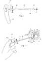
- FIG. 1is a perspective view of a mechanical tool for creating voids in interior body regions and illustrating pivoting movement of the cutting tip in phantom.
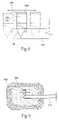
- FIG. 2is a perspective view of a bone treatment device.
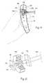
- FIG. 3is a perspective view illustrating insertion and use of the device of FIG. 2 in a vertebra.
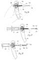
- FIG. 4is a perspective view of an alternative embodiment of a cutting tip and illustrating pivoting movement of the tip in phantom.
- FIG. 5is a front plan view of the tip shown in FIG. 4 and illustrating rotational movement of the cutting tip.
- FIG. 6illustrates 180° rotational movement of the cutting tip in a vertebra to create a 180° void.
- FIG. 7illustrates the shaft rotated 180° relative to FIG. 6 and the cutting tip again rotated 180° to form a 360° void.
- FIG. 8is a side view of the tip shown in FIG. 4 and illustrating translational movement of the cutting tip in a sawing-like motion.
- FIG. 9illustrates the translational movement of the cutting tip and formation of a void in a vertebra.
- FIG. 10is a perspective view illustrating the use of a marker band to identify the position of the cutting tip in relation to the distal end of the cannula.
- FIG. 11is a perspective view illustrating use of a stop to limit translational advancement of the shaft within a cannula.
- FIG. 12Ais an enlarged view of a groove located on the shaft of the cutting tool.
- FIG. 12Bis a perspective view of an alternative embodiment of a shaft in which a portion of the shaft is formed of a material of reduced strength and/or rigidity relative to the rest of the shaft.
- FIG. 13is a perspective view of an alternative embodiment of a stop that limits translational and rotational movement of the shaft along and within the cannula.
- FIG. 13Ais a perspective view of an alternative embodiment of a T-shaped slot that limits translation and rotational movement of the shaft along and within the cannula.
- FIG. 14is a schematic view representing the preset size and configuration of a void formed by performing a full sweep motion of a cam follower along a cam surface.
- FIG. 15is a perspective view of an alternative embodiment of a cutting tip and illustrating pivoting movement of the tip in phantom.
- FIG. 16is a front plan view of the tip shown in FIG. 15 and illustrating rotational movement of the cutting tip.
- FIG. 17is a perspective view of an alternative embodiment of a cutting tip and illustrating pivoting movement of the tip in phantom.
- FIG. 18is a front plan view of the tip shown in FIG. 17 and illustrating rotational movement of the cutting tip.
- FIG. 19is a sectional view of an actuator mechanism for deploying a cutting tip and showing placement of the tool in the user's hand.
- FIG. 20is a close-up and partial sectional view of the thumbwheel, threaded cap, flange, and stop of FIG. 19 .
- FIG. 21is a cut-away view of the tether and hinge mechanism of the cutting tip.
- FIG. 22is a side sectional view of an alternative embodiment of an actuator mechanism in which a lever actuates movement of the plunger rod.
- FIG. 23is a perspective view of a tool incorporating an alternative embodiment of an actuator mechanism.
- FIG. 24is a top sectional view of an alternative embodiment of an actuator mechanism.
- FIG. 25is a side sectional view of an alternative embodiment of an actuator mechanism and showing placement of the tool in the user's hand.
- FIG. 26is a side partial section view illustrating an alternative embodiment of a mechanical bone cutting tool illustrating the cutting tip in a straightened or malleable state and retracted within a cannula.
- FIG. 27is a view similar to FIG. 26 and illustrating advancement of the cutting tip beyond the distal tip of the cannula and the introduction of fluid to activate the cutting tip.
- FIG. 28is a view similar to FIG. 27 and illustrating activation of the cutting tip to a predetermined configuration.
- FIG. 29is a side view of an alternative embodiment of a cutting tip illustrating the cutting tip in a straightened or malleable state.
- FIG. 30is a view similar to FIG. 29 illustrating the cutting tip in the activated state.
- FIG. 31is a side view of an alternative embodiment of a cutting tip illustrating the cutting tip in a straightened or malleable state.
- FIG. 32is a view similar to FIG. 31 illustrating the cutting tip in the activated state.
- FIG. 33is a side view of an alternative embodiment of a cutting tip carried by a shaft and illustrating a dual lumen extending through the shaft into the cutting tip.
- FIG. 34is a side view of an alternative embodiment of a cutting tip illustrating a throughbore extending through the cutting tip.
- FIG. 35Ais a side view illustrating a pre-bent or formed cutting tip confined by a cannula.
- FIG. 35Bis a side view similar to FIG. 35A illustrating the deployment of the pre-bent or formed cutting tip by extension of the tip beyond the cannula.
- FIG. 36is a side view of an alternative embodiment of a mechanical void-creating device.
- FIG. 37is a side view of an alternative embodiment of a mechanical void-creating device.
- FIG. 38is a side view of an alternative embodiment of a mechanical void-creating device.
- FIG. 39is a top view of the device shown in FIG. 38 .
- FIG. 40is a side view of an alternative embodiment of the device of FIGS. 38 and 39 in which spring blades extend from the device.
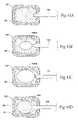
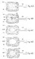
- FIGS. 41A–Dillustrate a method of creating and filling a void in bone in which a first mechanical cutting tool is used to create a void in bone and a second mechanical cutting tool is used to expand and/or further define the void.
- FIGS. 42A–Eillustrate an alternative method of creating and filling a void in bone in which a first mechanical cutting tool is used to create a void in bone and a second mechanical cutting tool and then an expandable body are used to expand and/or further define the void.
- FIGS. 43A–Dillustrate an alternative method of creating and filling a void in bone in which a first expandable body is used to create a void in bone and a second expandable body is used to expand and/or further define the void.
- FIGS. 44A–Eillustrate an alternative method of creating and filling a void in bone in which a first expandable body is used to create a void in bone and a second expandable body and then a mechanical cutting tool are used to expand and/or further define the void.
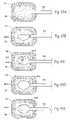
- FIGS. 45A–Eillustrate an alternative method of creating and filling a void in bone in which a first expandable body is used to create a void in bone and a mechanical cutting tool and then a second expandable body are used to expand and/or further define the void.
- FIGS. 46A–Eillustrate an alternative method of creating and filling a void in bone in which an expandable body is used to create a void in bone and a first mechanical cutting tool and then a second mechanical cutting tool are used to expand and/or further define the void.
- FIGS. 47A–Eillustrate an alternative method of creating and filling a void in bone in which a first cutting tool is used to create a void in bone and an expandable body and then a second mechanical cutting tool are used to expand and/or further define the void.
- FIGS. 48A–Eillustrate an alternative method of creating and filling a void in bone in which a mechanical cutting tool is used to create a void in bone and a first expandable body and then a second expandable body are used to expand and/or further define the void.
- the systems and methods embodying the inventioncan be adapted for use virtually in any interior body region, where the formation of a cavity or void within tissue is required for a therapeutic or diagnostic purpose.
- the preferred embodimentsshow the invention in association with systems and methods used to treat bones. This is because the systems and methods which embody the invention are well suited for use in this environment. It should be appreciated that the systems and methods which embody features of the invention can be used in other interior body regions, as well.
- cutting tipsare described below in detail.
- their sizes and shapescould be produced to fit the ideal void to be formed, whether it is a void in a tibia or a vertebral body.
- these mechanical toolscould be made of any bio-compatible metal (for example, but not limited to stainless steel, titanium, titanium alloys, tantalum, aluminum, aluminum alloys, or other metals) that has adequate shear and tensile strength to perform their void-forming function. Plastic polymers having suitable biomechanical properties may also be used for these tools.
- the toolmay be plated or coated with a biocompatible material.
- FIGS. 1–3show a tool 10 capable of forming a cavity or void in a targeted treatment area.
- the tool 10comprises a shaft 12 having a proximal and a distal end, respectively 14 and 16 .
- the shaft 12preferable includes a handle 18 to aid in gripping and maneuvering the shaft 12 through a pre-formed access path into bone.
- the handle 18can be made of any suitable material, e.g., any rigid polymer or metal or combination thereof, secured about the shaft 12 .
- the handle 18is desirably sized and configured to be securely and comfortably grasped by the physician.
- the shaft 12carries a void-forming structure 20 at its distal end 16 .
- the structure 20takes the form of a multi-faceted cutting tip 20 .
- the cutting tip 20may be adapted for use in various body regions, e.g., to create a void in bone.
- the cutting tip 20may also serve to remove hard or soft tumors from tissue.
- a cutting tipis a surface adapted to mechanically form a void in bone through contact with the bone, e.g., by cutting, shearing, scooping, shaving, sciving, dissecting, or scoring of the bone.
- the cutting tip 20is hingedly coupled to distal end 16 of the shaft 12 .
- the cutting tip 20is desirably adapted to extend radially from the shaft 12 and radially from the pre-formed access path to a diameter that is greater than a diameter of the access path.
- the cutting tip 20can be made of any suitable biocompatible material, e.g., stainless steel, cobalt chromium, titanium and alloys or mixtures thereof.
- the shaft 12 and cutting tip 20can alternatively be made of different materials (e.g. alloys of stainless steel with different strengths: 303 stainless steel, 304 stainless steel, 17 – 4 stainless steel, 17 – 7 stainless steel) and welded or otherwise bonded together.
- an actuatore.g., wheel 22 (see also, e.g., FIGS. 19 and 23 ), permits selective movement of the cutting tip 20 from a first, closed or non-deployed position to a second, open or deployed position.
- the cutting tip 20In the closed position (represented by solid lines in FIG. 1 ), the cutting tip 20 extends from the distal end 16 of the shaft 12 along the axis S of the shaft 12 . In this position, the shaft 12 can be easily passed through a cannula 23 or other instrument.
- the hinge mechanismpermits pivoting of the tip 20 at an angle A transverse to axis S of shaft 12 to the opened position (represented in phantom in FIG. 1 ).
- the cutting tip 20is adapted to pivot and be selectively secured in any pivot position from 0–90° relative to the axis S of the shaft 12 .
- the actuating mechanismprovides positive, controlled movement in both directions (i.e., from the open, deployed position to the closed, non-deployed position and from the closed, non-deployed position to the open, deployed position) during all degrees of actuation. That is, the secured pivot position and angle A are maintained regardless of the rotational orientation of the shaft 12 .
- the actuator mechanismprovides positive cutting action as the tip is actuated in either direction to provide bi-directional cutting. Actuation may be repeated so as to provide continuous cutting. The speed of actuation may be varied to vary the speed of cutting.
- the cutting tip 20also permits translational (i.e., longitudinal) movement along the axis S of the shaft 12 in a push-pull or sawing motion with the tip in the deployed position. The physician creates a desired void by repeated actuation, translational movement, or by performing a series of combined actuation and translational movements.
- the cutting tip 20is placed in the closed position extending from the distal end 16 of the shaft 12 , i.e., at a 0° angle A relative to axis S.
- the tool 10may be introduced into a targeted treatment site through an open procedure.
- the tool 10is introduced in a closed and minimally invasive procedure in which a percutaneous cannula 23 is advanced into a desired treatment region, e.g., a vertebral body 37 .
- the shaft 12is then passed through the cannula 23 and the cutting tip 20 is extended beyond the distal end of the cannula 23 .
- the cannula 23may be removed after introduction of the tool 10 .
- Fluoroscopy or other visualization techniquesmay be employed to aid in introducing the cannula 23 and tool into the targeted treatment area.
- the cutting tip 12is then pivoted to a desired position, i.e., preferably any position between 0–150°, and most preferably about 90°. Also, conceivably the tip 20 could deploy in either direction without stopping in the non-deployed condition. Actuation may be repeated and the shaft 12 advanced in fore and aft directions by pushing and pulling in a sawing-like motion to thereby create a void.
- shaft 12may be repositioned any number of times to produce a void of a desired configuration.
- the cannula 23desirably incorporates a distal portion having a reduced profile.
- the cannula 23includes a large diameter portion 25 , a small diameter distal portion 27 , and a transition portion 29 .
- the cannula 23may provide a taper between the large and small diameter portions 25 and 27 (not shown).
- the shaft 12 of the tool 10is desirably sized to fit within a lumen 31 extending through the cannula 23 , and may be of a constant or varying size.
- the reduced distal tip diameter of the cannula 23will allow the tip of the tool 10 to be inserted into the targeted bone, with a corresponding reduction in the size of the access path created in the bone.
- the smaller diameter section 27 of the cannula 23will pass through the cortical wall into the bone, while the larger diameter section 25 can abut against the outside of the bone (sealing the opening, if desired), and will desirably stretch, but not tear, softer tissues.
- the smaller diameter portion 27is desirably sized such that, when the larger diameter portion 25 abuts the cortical bone 33 of the pedicle 35 , the distal end of the smaller diameter portion 27 extends through the pedicle 35 and emerges into the vertebral body 37 and enters into cancellous bone 39 .
- the tool 10could be sized such that, when fully inserted into the cannula 23 , the distal cutting tip 20 would be prevented from contacting and/or breaching the anterior cortical wall 41 of the vertebral body 37 or targeted bone.
- FIGS. 4–9illustrate an embodiment of a cutting tool 100 having a cutting tip 120 which permits translational, rotational, or simultaneous translational and rotational movement of the cutting tip using an ergonomic and natural motion.
- the cutting tipis made from any suitable biocompatible material, e.g., stainless steel.
- the cutting tip 120provides a pivot region 124 hingedly attached to a shaft 112 , e.g., pivot pin 126 passes through hole 128 in pivot region 124 and into shaft 112 .
- This arrangementpermits a wide range of pivot motion allowing the cutting tip to pivot at virtually any desired angle.
- the cutting tip 120is adapted to pivot from 0–90° relative to the axis S of the shaft 112 . Similar to the embodiment of FIG. 1 , the actuating mechanism is positive in both directions.
- a collar 130divides the pivot region 124 and a trunk region 132 and provides additional strength and support to the cutting tip 120 .
- the maximum width (W) of the trunk 132is parallel to the axis S of the shaft 112 when the tip 120 is deployed at 900 (illustrated in phantom in FIG. 4 ).
- the trunk 132carries a cutting disc 134 providing a dual rounded cutting surface extending on either side of the trunk 132 , providing a 360° cutting surface.
- the diameter of disc 134is approximately the same as the diameter of the shaft 112 so as to minimize stress on the tip 120 during cutting and to provide ease of passage through a cannula.
- the tipincludes a flat or straight cutting surface 136 along the tip of the disc 134 that provides greater ease in cutting bone on the pullback motion.
- the shaft 112When pushing, the shaft 112 provides the strength and force for cutting.
- the disc 134 and trunk 132 togetherprovide a large surface contact area that enables the tip 120 to take an aggressive bite into bone and gouge bone material in large chunks.
- the disc configurationallows rotational cutting in both clockwise and counterclockwise directions.
- the tip 120is extended to a desired angle A, e.g., 90° along axis T.
- the shaft 112is then rotated 0–90° in a first direction (represented by arrow 138 ) relative to axis T.
- the shaft 112can be rotated 0–90° in the opposite direction (represented by arrow 140 ) relative to axis T to create a void extending 180° by a simple turning of the physician's wrist.
- FIG. 6illustrates rotation of the cutting tip 120 in bone, e.g., a vertebra 142 , to create a 180° void.
- the shaft 112may be rotated 180° and again aligned approximately along axis T. The shaft 112 is then rotated 0–90° in a first direction (represented by arrow 144 ) relative to axis T. The shaft 112 can be rotated 0–90° in the opposite direction (represented by arrow 146 ) relative to axis T to create a void extending 360°.
- the physiciancan monitor the position of the tip 120 with use of fluoroscopy.
- the disc configurationalso allows translational cutting in a push-pull or sawing motion as represented by arrows in FIGS. 8 and 9 .
- the physicianmay deliver translational and rotational forces simultaneously by pushing in and pulling out while simultaneously rotating a handle or alternating rotational and translational motions. In this manner, the physician controls rotational and translational movement of the cutting tip 120 to create a void of desired size and shape, e.g., cylindrical.
- the shaft 112carries a boss or stop 102 designed to limit forward, i.e., translational, motion of the shaft 112 within a cannula 104 .
- the diameter of the stop 102approximates the diameter of the cannula 104 so that the stop 102 rests against the face or top 106 of the cannula 104 to stop forward advancement of the shaft 112 within the cannula 104 .
- the stop 102is positioned on the shaft 112 such that there is sufficient room to accommodate the physician's fingers wrapped around and under the handle 18 .
- the stop 102thus provides clearance between the physician's fingers and the percutaneous access cannula 104 , preventing pinching or catching of the physician's fingers.
- the stop 102stops insertion of the shaft 112 to leave a comfortable working distance for the physician's hand when rotating the shaft 112 (i.e., a sweeping cutting motion) or when using a push-pull cutting motion or a combination of both cutting motions.
- the stop 102is positioned approximately 1.75 inches (about 4.5 cm.) from the base of the handle 18 .
- the stop 112prevents advancement of the shaft 112 (and void-forming structure 20 ) within the vertebral body. This prevents the possibility of puncturing or breaching the anterior cortical wall of the vertebra 142 (see also FIG. 9 ).
- a marker band 101is positioned distal of the stop 102 .
- the marker band 101is aligned with the face 106 of the cannula 104 as the cutting tip 120 is exiting the cannula 104 into a bone, e.g., a vertebra 142 .
- the tip 120extends beyond the distal end 103 of the cannula 103 .
- the marker band 101is located approximately 3 cm. distal of the stop 102 .
- the tip 120extends approximately 3.5 cm. from the distal end 103 of the cannula 104 when the cutting tip 120 is in the non-deployed position (i.e., aligned with the axis S of the shaft 112 ), and approximately 3 cm. from the distal end 103 of the cannula 104 when the tip 120 is in the deployed position (e.g., at 90°).
- a groove 105is positioned proximal the stop 102 .
- the groove 105is a turned angular cut having an angle G with a radius R on the shaft 112 to define a line of weakness on the shaft 112 .
- the mean torque required for failure of the shaft 112 at groove 105(the maximum shaft torque) is less than the torque required for failure of the shaft 112 at pin 126 (the maximum hinge torque) (see also FIG. 4 ), or more generally, of the cutting assembly itself.
- the mean torque required to scrape normal boneis approximately 2.0 in.-lb.
- the mean torque required for failure of the shaft 105 at groove 105is approximately 7.3 in.-lb.
- the mean torque required for failure at pin 128is 9.3 in.-lb.
- the groove 105results in the shaft 112 breaking or severing at the groove 112 before the tip 120 breaks or fails at the pivot region 124 . This provides an additional safety feature that allows the shaft 112 and undeformed pivot region 124 to be safely removed from the cannula 104 without complications. Failure or deformation of the pivot region 124 is avoided.
- the region of weaknesscan also be formed by any of a variety of other suitable means that provide that the shaft 112 will sever or break prior to the tip 120 becoming uncoupled from the shaft 112 (i.e., that provide that the maximum hinge torque is greater than the maximum shaft torque).
- a portion 111 of the shaft 112may be formed of a material of reduced strength and/or rigidity relative to the remaining portions 113 A and 113 B of the shaft 112 to define a region of weakness.
- shaft portions 113 A and 113 Bare formed of a biocompatible metal and shaft portion 111 is formed of a biocompatible plastic material.
- the shaft 112may also carry a boss or stop 102 with a tine or lug 108 that selectively mates with a complementary slot or groove 110 in a cannula 104 or other access device so as to limit rotational motion to a preset angle.
- the slot or groove 110defines a cam surface.
- the tine or lug 108serves as a cam follower.
- the configuration of the cam surface and cam followercan vary, but preferably define a system in which a sweep of the cam follower across the full range of motion of the cam surface consistently creates a void of a predetermined size and shape.
- FIG. 13shows an embodiment in which the cam surface takes the form of an elongated slot 110 in the circumferential margin of the cannula 104 .
- the depth of reachis defined by the depth of the slot. That is, the length LS of the slot limits forward advancement of the stop 102 (and therefore the shaft 112 ) within the cannula 104 .
- the width WS of the slotis greater than the width WC of the lug or tine 102 by a pre-determined amount.
- the angle of rotationis controlled by the extent of the slot 110 , i.e., the difference in width between the slot 110 and the width of tine or lug 108 (i.e., the difference between WS and WC).
- FIG. 14illustrates the formation of a pre-determined pie-shaped void having an angle Al.
- the pre-determined voidhas a length corresponding to the length LS of slot 110 as shown in FIG. 13 .
- the slot 110can be varied, e.g., by varying the width of the slot 110 along its length, to form voids of a desired, pre-determined shape and size.
- FIG. 13Aillustrates an alternative embodiment of a slot 110 A in which the slot 110 A is generally T-shaped and adapted to form a pre-determined void biased such that the most forward portion is of greater volume, with each volume also being wedge shaped.
- the tool 100is introduced into a targeted treatment site.
- the tool 100is introduced in a closed and minimally invasive procedure in which a percutaneous cannula 104 is advanced into a desired treatment region, e.g., a vertebral body. Introduction of the tool may be assisted by conventional visualization techniques, as previously described.
- the shaft 112is then passed through the cannula 104 and the cutting tip 120 is extended beyond the distal end of the cannula 104 .
- the cutting tip 112is then pivoted to the desired position, i.e., any position between 0–90°.
- the physicianmanipulates the cutting tip 120 by sweeping the shaft 112 along the full range of motion of the cam surface and cam follower.
- the stop 102serves to limit translational movement of the shaft 112 along the cannula 104 and the lug or tine 108 limits rotational movement of the shaft 112 within the cannula 104 to create a void of a pre-determined size and shape. Because the void created is of a consistent and pre-determined size and shape, visualization is not required during cutting and void formation. The need for fluoroscopy or other visualization techniques is thereby reduced, limiting the patient's exposure to radiation or dyes.
- the cutting tip 112Upon completion of the procedure, the cutting tip 112 is returned to the non-deployed position and the cannula 104 and tool 100 are withdrawn.
- FIGS. 15 and 16illustrate an alternative embodiment of a tool 200 for creating voids in interior body regions.
- the trunk 232is tapered and rotated 90° relative to the embodiment shown in FIGS. 4–9 so that the maximum width W of the trunk is perpendicular to the axis S of the shaft 212 when the tip 220 is deployed at a 90° angle A from the axis S of the shaft 212 .
- This arrangementminimizes the combined surface area of the disc 234 and trunk 232 in contact with the bone during scraping and cutting and thus minimizes transmission of significant force and stress to the hinge mechanism.
- the disc 234has a convex front surface 248 providing a dome-shape.
- the disc 234has a diameter that is approximately the same as the diameter of the shaft 212 , minimizing stress on the tip 220 during cutting and providing ease of passage of the tip 220 through a cannula.
- the domed configurationfacilitates cutting and scraping of bone by producing leverage on the bone that allows the tip 220 to roll out of the bone easily.
- the domed configurationallows the tip to easily release from bone and to disengage from the bone for easy withdrawal.
- the disc 234provides a 360° cutting surface and permits both translational and rotational movement of the cutting disc 234 when deployed at the desired angle A, as previously described.
- FIGS. 17 and 18illustrate another alternative embodiment of a tool 300 for creating voids in interior body regions.
- the trunk 332is tapered similar to the embodiment of FIGS. 15 and 16 , but is conical.
- the trunk 332also carries a dome-shaped disc 334 allowing both translational and rotational cutting, similar to the embodiment of FIGS. 15 and 16 .
- the combined cutting surface of the disc 334 and trunk 332is minimized and is designed to reduce the force and stress on the hinged mechanism by minimizing the contact area in the bone in all directions.
- the same profile(symmetrical cross-section of the conical trunk 332 ) is presented to the bone regardless of whether pushing or pulling (translational) force, turning (rotational) force, or a combination of both forces is applied.
- FIGS. 19–22illustrate one embodiment of an actuator mechanism for use with a void-forming tool.
- the actuator mechanismconverts rotational motion into translational movement to control the deployment of a cutting tip.
- the actuator mechanismis illustrated with the cutting tip 120 embodiment of FIGS. 4–9 .
- the actuator mechanismprovides a thumbwheel 150 , an insert or cap 152 , flange 154 , plunger rod 156 , and rotational stop 158 .
- the thumbwheel 150 , cap 152 , flange 154 , plunger rod 156 , and stop 158may be made of any suitable metal.
- the thumbwheelis seated in a free-floating manner in a slot 160 within handle 18 .
- the handle 18is made of a strong and durable polymer plastic.
- the thumbwheel 150extends, at least in part, from the handle 18 for manipulation by the thumb or index finger of the user, as seen in FIG. 19 .
- the thumbwheel 150desirably includes grooves or knurls for easy grasping and manipulation. While the thumbwheel 150 may be configured for manual manipulation, it is contemplated that the actuator may also be power-driven.
- the cap 152is seated within the thumbwheel 150 and is desirably threaded or otherwise adapted to engage the wheel 150 so as to move with the wheel 150 .
- the cap 152is connected, e.g., by welding, to the plunger rod 156 .
- the transmission ratio, and therefore the amount of torque delivered,may be controlled by altering the thread pitch of the cap 152 .
- the plunger rod 156is sized and configured to be seated within the shaft 112 and to extend beyond the shaft 112 and thumbwheel 150 through bores in the cap 152 and thumbwheel 150 .
- the thumbwheel 150 and shaft 112are positioned offset on the handle 18 for placement of the shaft 112 between the index and middle finger, as seen in FIG. 19 .
- the distal end of the plunger rod 156is coupled to tether wire 166 .
- the tether 160is looped to pass through holes 168 in cutting tip 120 below pin 126 and is swaged or welded to the plunger rod 156 .
- Movement of plunger rod 156regulates pressure on the tether 160 to actuate the tip 120 between the deployed and non-deployed positions.
- the tether 160will keep the tip 120 attached to shaft 112 in the event of breakage or failure of pin 126 to permit easy removal. This prevents parts from being left behind during removal, thereby providing an additional safety feature.
- the tip 120may be additionally tethered to the shaft 112 by any of a variety of ways to provide that the tip 120 remains tethered to the shaft 112 if the coupling element (e.g., pin 126 ) becomes inoperable.
- the tip 120is additionally tethered to shaft 112 by a cable or pulley (not shown).
- the flange 154is seated in a slot 170 within the handle 18 and is coupled to the shaft 112 , e.g., by welding or by interference or compression fit. Desirably, the flange 154 includes an offset bore such that there is only one way in which it may be seated with slot 170 .
- the flange 154engages the shaft 112 within the handle 18 and is sized and configured to essentially prevent rotational movement of the shaft 112 .
- the rod 156has a rectangular end 172 sized and configured to pass through a complementary rectangular opening 174 in the stop 158 .
- the stop 158engages the rod 156 to prevent rotation of the rod 156 during actuation.
- the stop 158is mounted to the plunger rod 156 and seated exterior to and against slot 160 .
- the arrangement of the metal stop 158 against the plastic slot 160creates additional frictional forces to provide additional strength and reinforcement and serves to limit the amount of torque delivered to the plunger rod 156 .
- Rotation of the thumbwheel 150 in a first directionadvances the plunger rod 156 in a first direction along the shaft 112 to decrease tension on wire 166 and actuate deployment of the cutting tip 120 .
- Rotation of the thumbwheel 150 in the opposite directionadvances the plunger rod in the opposite direction within the shaft 112 and increases tension on wire 166 to actuate movement of the cutting tip 120 from the deployed to the non-deployed position.
- This arrangementconverts the rotational movement of the thumbwheel 150 into the translational movement of the plunger rod 156 .
- a lever 176is hingedly attached to the plunger rod 156 . Movement of the lever 176 in a first direction advances the plunger in a first direction to deploy the cutting tip 120 , and movement of the lever 176 in the opposite direction advances the plunger 156 in a second direction to move the cutting tip 120 from the deployed to the non-deployed position. In this manner, the lever 176 permits the physician to continuously and conveniently move the tip 120 itself without moving the shaft 112 to create a reciprocating cutting motion.
- FIGS. 23–25illustrate an embodiment of an actuator similar to the embodiment of FIGS. 19–21 .
- the actuatorprovides a series of gears that interact to convert rotational motion to translational motion.
- a central gear 178is similar in configuration and function to the thumbwheel 150 shown in FIGS. 19–21 .
- the central gear 178 and shaft 112are centered along the bottom of the handle 18 for placement of the shaft 112 between the middle and ring fingers.
- Control knobs 180 A and 180 Bare provided at each end of the handle 18 for actuation by the user's thumb. Alternatively, the control knobs 180 A and 180 B may be driven by a motor. Each control knob 180 A and 180 B defines a gear that actuates a corresponding intermediate gear 182 A or 182 B positioned between the control knob 180 A or 180 B and the central gear 178 . Rotation of the control knob 180 A or 180 B actuates the corresponding intermediate gear 182 A or 182 B and the central gear 178 . Rotational movement of the control knob 180 is thereby converted into translational movement of the plunger rod 156 , similar to the previous embodiment.
- the symmetric designis designed for easy use by either the right or left hand. Further, the symmetric design allows easy rotation of the handle 18 .
- the shaft 112is advanced through a cannula 104 .
- the cutting tip 120is extended beyond the distal end of the cannula 104 .
- a control knob 180 A or 180 Bis rotated to deploy the cutting tip 130 to the desired angle.
- the physicianthen creates a desired void by performing a series of translational and rotational movements of the shaft 112 .
- the physicianthen returns the cutting tip 120 to the non-deployed position.
- the handle 18can then be rotated 180°.
- the opposing control knob 180 A or 180 Bis then manipulated to again deploy the cutting tip 120 to a desired angle and another series of translational and rotational movements may be performed.
- the physicianreturns the tip 120 to the non-deployed position.
- the tool 100is withdrawn from the patient.
- the physicianthen completes the procedure by filling the void with a bone cement or bone substitute, removing the cannula 104 , and closing the incision.
- the rate and/or force of cuttingmay be controlled by altering the transmission ratio.
- the forcemay be varied by varying the screw thread pitch or the transmission gear ratio.
- the rate of motioni.e., speed of actuation
- the rate of motionmay be varied by manually or mechanically varying the speed of actuation.
- FIGS. 26–28illustrate an embodiment of a tool 700 employing a cutting tip 720 formed of a shape memory alloy.
- Use of a shape memory alloyallows for a smaller instrument as the hinge mechanism is no longer needed to activate the tip. Smaller instruments are safer and can access smaller vertebral bodies located higher in the spine. Smaller instruments are also less invasive and are less traumatic to the patient, allowing for a faster recuperation time.
- the rod 701has a malleable or straightened state ( FIGS. 26 and 27 ) and an activated or articulated predetermined, desired state ( FIG. 28 ).
- the rod 701is sized and configured for passage in a straightened or malleable state through a cannula 104 into a vertebra or any bone surface.
- the rod 701returns to its predetermined, desired memory shape as a result of either the body temperature of the patient or by means of an electrical impulse (e.g., cooling, heat, voltage, etc.).
- an electrical impulsee.g., cooling, heat, voltage, etc.
- the distal end of the rod 701is activated to an angle, e.g., 90°, to form an elbow defining a cutting tip, as shown in FIG. 28 .
- the length from the distal end of the rod to the bendis approximately 0.5 cm.
- Cutting of the boneis accomplished by a rotating motion or a push-pull motion or a combination of both motions, as previously described.
- the rod 701desirably includes a lumen 703 that permits introduction of a cooling or heating media (S), e.g., saline, to return the rod 701 to a straightened state allowing for easy withdrawal.
- Scooling or heating media
- the rod 701is formed from a shape memory alloy with an activation temperature that is equal to room temperature, i.e., the rod 701 is fully austenitic at room temperature. Therefore, the rod 701 is fully articulated to its predetermined shape at room temperature.
- the rod 701is chilled to a martensitic condition (malleable state) prior to insertion into bone, allowing for easy insertion.
- the rod 701articulates to the predetermined, desired position upon returning to room temperature. This ensures that the proximal end of the cutting tip 720 attains full activation without depending on heat transfer from the distal end of the rod 701 (which is in contact with the patient) or any outside means (e.g., heat, voltage, etc.).
- a lumen 703is provided in the rod 701 to facilitate the introduction of a cooling media (S), e.g., chilled saline, to deactivate the material and allow for easy withdrawal.
- a cooling mediae.g., chilled saline
- the alloyis super-elastic and the cannula 104 confines the pre-bent or formed cutting tip 720 until the activation mechanism deploys the cutting tip 720 to extend beyond the cannula 104 (see FIGS. 35A and 35B ).
- the rod 701may be used to straighten the cannula 104 which is formed of a shape memory alloy.
- the cutting tip 720is disposed on the shape memory cannula 104 (not shown).
- the cannula 104is educated to have a curved tip the rod 701 is moveably disposed within the cannula 104 to straighten the cannula 104 by fully engaging the rod 701 within the cannula 104 (i.e. by pushing the rod 701 ) and to allow the cannula 104 and cutting tip 720 to curve or articulate by pulling back on the rod 701 .
- the rod 701is made of a rigid material, such as stainless steel.
- the activation temperature of the alloyis set at a temperature higher than body temperature.
- the rod 701is malleable for insertion and withdrawal. The rod 701 achieves full activation to its predetermined shape only through the application of heat or voltage. This permits control of the change of the state of the rod 701 from malleable to the predetermined shape, or any percentage there between, using a potentiometer or other suitable device.
- the rod 701may be attached to a handle by a standard square drive or Hudson-style orthopedic fitting on the proximal end (not shown).
- a torque-regulating handlecould be mated to the rod 701 to allow for torque-limiting rotational scraping.
- the rod 701is fixedly attached or otherwise coupled to a handle 18 having an actuator mechanism.
- the rod 701is coupled to a thumbscrew 152 and is driven by an actuator mechanism similar to the mechanism illustrated in FIGS. 19 and 20 .
- the rod 701is actuated (moved in fore and aft directions) within the cannula 104 by the actuator mechanism. This permits the cutting tip 720 to be retracted ( FIG. 26 ) in a malleable state within the cannula 104 for easy insertion and withdrawal and then extended ( FIG. 27 ) beyond the distal end of the cannula 104 within bone and activated for use ( FIG. 28 ).
- the handle 18includes a luer fitting 705 .
- the fitting 705is sized and configured to mate with a complementary luer fitting 707 on a fluid introduction device, e.g., a syringe 709 , to establish fluid communication between the lumen 703 and the fluid introduction device 709 .
- Fluide.g., chilled or heated saline, may be introduced from the syringe 709 through the rod lumen 703 to control movement of the rod 701 between the malleable (deactivated) and activated states.
- a cutting tip 720 A of a desired configurationis formed at the distal end of the malleable rod 701 .
- the tip 720 Amay be a separate piece welded to the rod 701 , or the tip 720 A may be carved or otherwise formed in the rod 701 , e.g., by conventional machining techniques.
- the cutting tip 720 Ais of a conical trunk and domed disc configuration similar to the embodiment illustrated in FIGS. 17 and 18 . It is apparent, however, that the configuration of the cutting tip 720 A can be varied according to the procedure being performed and/or to accommodate individual anatomy.
- the entire rod 701including the cutting tip 720 A, are formed of the shape memory alloy.
- the rod 701yields from a malleable state ( FIG. 29 ) to the activated state ( FIG. 30 ) as previously described.
- the rod 701desirably includes a lumen 703 to permit introduction of a fluid media to control movement between the deactivated and activated states, as also previously described.
- the tip 720 A and a distal portion 711 of the rod 701are formed of a shape memory alloy.
- a rod body 713is formed of any suitable biocompatible, surgical grade material.
- the distal portion 711carrying the cutting tip 720 A, is welded or otherwise fixed to the rod body 713 .
- the distal portion 711 of the rod 701yields from a malleable state ( FIG. 31 ) to the activated state ( FIG. 32 ).
- the rod 701desirably includes a lumen 703 to permit introduction of a fluid media to control movement between the deactivated and activated states.
- the rod 701may include a dual lumen 714 so that fluid media can circulate through the shaft 112 and desirably through the cutting tip 720 (see FIG. 33 )
- the rod 701may include a throughbore 703 A to accommodate more thermal flow (see FIG. 34 ).
- FIG. 36shows an alternative embodiment of a mechanical tool 400 for creating a void in an interior body region.
- a shaft 412carries a sharp, stout, metal spring 420 on the end of a shaft 412 .
- the shaft 412can be rotated against the direction of the spring 420 causing it to cut bone (or other tissue) in an expanding fashion.
- the tool 400is sized and configured to be introduced through a cannula (not shown) with the spring 420 extending beyond the cannula and the shaft 412 rotated into the tissue a short distance at a time.
- the shaft 412can then be withdrawn to remove any captured tissue. If no tissue is captured, the tool 400 is reintroduced farther into the tissue and tissue removal is again attempted.
- the tool 400may also be used to loosen tissue to allow better cutting and/or removal by other mechanical tools.
- FIG. 37shows another embodiment of a mechanical tool 500 for creating a void in an interior body region.
- Two or more fingers 520are carried on the distal end of a shaft 512 .
- the shaft 512carries four fingers 520 , two fingers 520 facing each other.
- the fingers 520are introduced into the tissue through a cannula (not shown), and then mechanically closed with a pulley-type system or other similar system to grab tissue for extraction.
- the fingers 520are adapted to further expand as the size of the void increases. It is apparent that the length of the fingers 520 may be chosen to suit the intended use and particular individual anatomy.
- FIGS. 38 and 39show another embodiment of a mechanical tool 600 for creating a void in an interior body region.
- the toolincludes a hinged void-creating device 620 carried on the distal end of the shaft 612 .
- the void-creating device 620may be used to create a void or to loosen tissue to allow better cutting and removal by other mechanical tools.
- the void-creating device 620provides for adjusting the height of the device 620 .
- a positioning rod 621is coupled to the device 620 for expanding and contracting the device 620 .
- the heightmay be adjusted by drawing in the rod 621 to increase the height H and pushing out on the rod to decrease the height H of the device 620 .
- Calibrated markings(not shown) may be provided on the rod handle to indicate the dimension of the device 620 as the rod 621 is drawn back or advanced.
- the height Hmay also be chosen to suit the intended use and particular individual anatomy.
- FIG. 40shows an embodiment similar to FIGS. 35 and 36 , but additionally providing a spring blade or series of spring blades 623 for more aggressive cutting.
- the spring blades 623are coupled to the last blades out of the cannula and desirably pre-bent to cut parallel to the end plates.
- Two or more different mechanical cutting tools of the type describedmay also be used in combination to form a cavity or void of a desired size and configuration in a targeted bone.
- one or more mechanical cutting toolsmay be used in combination with one or more expandable void-creating tools to form the desired void.
- Expandable structures for creating voids in bonesare described in U.S. Pat. Nos. 4,969,888, 5,827,289, 5,972,015, 6,235,043, 6,248,110, and 6,607,544, all of which are herein incorporated by reference.
- Fracture reduction and deformity correctionis influenced by a variety of factors, including, but not limited to, acuteness of the fracture, bone quality (e.g. osteoporosis, bone cancers, steroid-induced osteoporosis), and healing.
- bone qualitye.g. osteoporosis, bone cancers, steroid-induced osteoporosis
- healinge.g. osteoporosis, bone cancers, steroid-induced osteoporosis
- expansion of the expandable structuremay be distorted by a region or regions of hard bone. This results in a high pressure within the expandable structure and low volume of expansion media within the expandable structure.
- the use of a mechanical cutting tool to selectively break up the region of hard bonewill allow the expandable structure to achieve a more consistent and reliable fracture reduction. Mechanical cutting or scraping tools will break bone, but an expandable structure is required for the en-masse endplate reduction and deformity correction.
- an access path to boneis made using a conventional access cannula by techniques commonly known in the art.
- a first void creatorwhich may be a mechanical cutting tool or an expandable structure, is then introduced into a bone to create a void.
- the first void creatoris then removed.
- a second void creatorwhich may be the same as or different from the first void creator, is then inserted into the bone to enlarge or further define the void to form a void of a desired size and configuration.
- the second void creatoris then removed.
- a third void creatorwhich may be the same or different from the first and/or second void creators, may then be introduced to further enlarge and define the void and then removed.
- a filling materiale.g., bone cement or bone substitute, is then injected or otherwise introduced into the void to fill the void.
- a first mechanical cutting tool 800 A and a second mechanical cutting tool 800 Bwhich may be different in size and/or configuration from the first cutting tool 800 A, are used to create a void 802 of a desired size and configuration.
- An access cannula 104is percutaneously introduced to provide an access path into a bone, e.g., a vertebra 142 ( FIG. 41A ).
- the first mechanical cutting tool 800 Ais introduced through the cannula 104 into the cancellous bone 39 of the vertebra 142 .
- the cutting tip 820 Ais manipulated in a series of longitudinal and/or rotational movements to create a void 802 in the cancellous bone 39 ( FIG. 41B ).
- the first cutting tool 800 Ais then removed.
- the second mechanical cutting tool 800 Bis then introduced and manipulated in a series of longitudinal and/or rotational movements ( FIG. 41C ).
- the second cutting tool 800 Bdesirably has a cutting tip 820 B of a different size and/or configuration to enlarge and/or otherwise further define the void 802 created by the first tool 800 A.
- the second cutting tool 800 Bhas a cutting tip 820 B of a greater height than the first cutting tip 820 A to enlarge the void 802 , but is of a similar configuration.
- a filler material 804e.g., bone cement or bone substitute, may then be introduced into the void 802 to fill the void 802 ( FIG. 41D ).
- an expandable structure 900may be introduced through the cannula 104 and expanded to enlarge and/or further define the void 802 created by the first and second mechanical cutting tools 802 A and 802 B.
- the expandable structure 900takes the form of a balloon adapted to expand or form a void by compression of cancellous bone
- the expandable structure 900may be any suitable device which can be expanded to enlarge and/or further define the void.
- the expandable structure 900may also be a mechanical jack, retractor, or spring.
- the expandable structure 900has a collapsed condition permitting insertion of the expandable structure 900 through the cannula 104 and an expanded condition in which the expandable structure 900 compacts cancellous bone 39 upon expansion within the cancellous bone 39 .
- the expandable structure 900is then removed.
- the void 802may then be filled, as previously described.
- a first expandable structure 900 A and a second expandable structure 900 Bwhich may be different in size and/or configuration from the first expandable structure 900 A, are used to create a void 802 of a desired size and configuration.
- An access cannula 104is percutaneously introduced to provide an access path into a vertebra 142 ( FIG. 43A ).
- the first expandable structure 900 Ais introduced through the cannula 104 in the collapsed condition into the cancellous bone 39 of the vertebra 142 .
- the expandable structure 900 Ais then expanded to create a void 802 in cancellous bone 39 ( FIG. 43B ).
- the first expandable structure 900 Ais then removed.
- the second expandable structure 900 Bis then introduced and expanded ( FIG. 43C ).
- the second expandable structure 900 Bis desirably of a different size and/or configuration such that expansion of the second expandable structure 900 B enlarges and/or otherwise further defines the void 802 created by the first expandable structure 900 A.
- the second expandable structure 900 Bis of a larger volume, but is of a similar configuration. It is contemplated, however, that the second expandable structure 900 B may be of a different configuration than the first expandable structure 900 A.
- the second expandable structure 900 Bis then removed.
- a filler material 804e.g., bone cement or bone substitute, may then be introduced into the void 802 to fill the void 802 ( FIG. 43D ).
- a mechanical cutting tool 800may be introduced through the cannula 104 to enlarge and/or further define the void 802 created by the first and second expandable structures 900 A and 900 B.
- the cutting tool 800is then removed.
- the void 802may then be filled, as previously described.
- FIGS. 45A–45Eillustrate another method of creating a void 802 in bone of a desired size and configuration.
- An access cannula 104is percutaneously introduced to provide an access path into a vertebra 142 ( FIG. 45A ).
- a first expandable structure 900 Ais introduced through the cannula 104 in the collapsed condition into the cancellous bone 39 of the vertebra 142 .
- the expandable structure 900 Ais then expanded to create a void 802 in cancellous bone 39 ( FIG. 45B ) Because the reticulum of the cancellous bone 39 may be somewhat dense, it may be difficult for the expandable structure 900 A to sufficiently compact the cancellous bone 39 to permit full expansion of the expandable body 900 A.
- the expandable structure 900 Amay expand preferentially in a given direction depending on the density of the reticulum, but is not able to expand to its full preformed shape, as seen in FIG. 45B .
- the first expandable structure 900 Ais then removed.
- a mechanical cutting tool 800is then introduced ( FIG. 45C ).
- the cutting tip 820is manipulated in a series of longitudinal and/or rotational movements to enlarge and/or otherwise further define the void 802 created by the expandable structure 900 A.
- the cutting tool 800is then removed.
- a second expandable structure 900 Bwhich may be of a different size and/or configuration from the first expandable structure 900 A, is then introduced prior to filling the void 802 ( FIG. 45D ).
- Use of the cutting tool 800 to break or cut the reticulum and expand the void 802allows the second expandable structure 900 A to fully expand.
- the second expandable structure 900 Ais then expanded to enlarge and/or otherwise further define the previously created void 802 .
- the second expandable structure 900 Bis then removed.
- the first expandable structure 900 Amay be reintroduced, re-expanded, and then removed.
- a filler material 804may then be introduced into the void 802 to fill the void ( FIG. 45E ).
- an access cannula 104is percutaneously introduced to provide an access path into a vertebra 104 ( FIG. 46A ).
- An expandable structure 900is introduced and expanded to create a void 802 in cancellous bone 39 ( FIG. 46B ) The first expandable structure 900 A is then removed.
- a first mechanical cutting tool 800 Ais then introduced ( FIG. 46C ).
- the cutting tip 820 Ais manipulated in a series of longitudinal and/or rotational movements to enlarge and/or otherwise further define the void 802 created by the expandable structure 900 .
- the cutting tool 800is then removed.
- a second mechanical cutting tool 800 Bwhich may be of a different size and/or configuration from the first mechanical cutting tool 800 A, is then introduced prior to filling the void 802 ( FIG. 46D ).
- the cutting tip 820 Bis manipulated in a series of longitudinal and/or rotational movements to enlarge and/or otherwise further define the void 802 created by the expandable structure 900 and first cutting tool 800 A.
- the second cutting tool 800 Bis then removed.
- a filler material 804may then be introduced into the void 802 to fill the void 802 ( FIG. 46E ).
- a first mechanical cutting tool 800 Ais introduced and manipulated in a series of longitudinal and/or rotational movements to create a void 802 .
- the first cutting tool 800 Ais then removed.
- An expandable structure 900is then introduced and expanded to enlarge and/or otherwise further define the void 802 created by the first cutting tool 800 A.
- the expandable structure 900is then removed.
- a second mechanical cutting tool 800 Bwhich may be of a different size and/or configuration from the first mechanical cutting tool 800 A, is then introduced prior to filling the void 802 .
- the cutting tip 820 Bis manipulated in a series of longitudinal and/or rotational movements to enlarge and/or otherwise further define the void 802 created by the expandable structure 900 A and first cutting tool 802 A.
- the second cutting tool 802 Bis then removed.
- a filler material 804may then be introduced into the void 802 to fill the void 802 .
- a second expandable structure 900 Bis introduced and expanded to enlarge and/or otherwise further define the void created by the first expandable structure 900 A and first cutting tool 800 A.
Landscapes
- Health & Medical Sciences (AREA)
- Life Sciences & Earth Sciences (AREA)
- Surgery (AREA)
- Orthopedic Medicine & Surgery (AREA)
- Medical Informatics (AREA)
- General Health & Medical Sciences (AREA)
- Biomedical Technology (AREA)
- Heart & Thoracic Surgery (AREA)
- Nuclear Medicine, Radiotherapy & Molecular Imaging (AREA)
- Molecular Biology (AREA)
- Animal Behavior & Ethology (AREA)
- Engineering & Computer Science (AREA)
- Public Health (AREA)
- Veterinary Medicine (AREA)
- Dentistry (AREA)
- Oral & Maxillofacial Surgery (AREA)
- Vascular Medicine (AREA)
- Surgical Instruments (AREA)
- Prostheses (AREA)
Abstract
Description
Claims (39)
Priority Applications (1)
| Application Number | Priority Date | Filing Date | Title |
|---|---|---|---|
| US10/892,824US6923813B2 (en) | 2003-09-03 | 2004-07-16 | Devices for creating voids in interior body regions and related methods |
Applications Claiming Priority (2)
| Application Number | Priority Date | Filing Date | Title |
|---|---|---|---|
| US49993403P | 2003-09-03 | 2003-09-03 | |
| US10/892,824US6923813B2 (en) | 2003-09-03 | 2004-07-16 | Devices for creating voids in interior body regions and related methods |
Publications (2)
| Publication Number | Publication Date |
|---|---|
| US20050113838A1 US20050113838A1 (en) | 2005-05-26 |
| US6923813B2true US6923813B2 (en) | 2005-08-02 |
Family
ID=34272890
Family Applications (2)
| Application Number | Title | Priority Date | Filing Date |
|---|---|---|---|
| US10/892,824Expired - Fee RelatedUS6923813B2 (en) | 2003-09-03 | 2004-07-16 | Devices for creating voids in interior body regions and related methods |
| US10/893,155AbandonedUS20050240193A1 (en) | 2003-09-03 | 2004-07-16 | Devices for creating voids in interior body regions and related methods |
Family Applications After (1)
| Application Number | Title | Priority Date | Filing Date |
|---|---|---|---|
| US10/893,155AbandonedUS20050240193A1 (en) | 2003-09-03 | 2004-07-16 | Devices for creating voids in interior body regions and related methods |
Country Status (10)
| Country | Link |
|---|---|
| US (2) | US6923813B2 (en) |
| EP (1) | EP1663029A4 (en) |
| JP (1) | JP4555293B2 (en) |
| KR (1) | KR101132644B1 (en) |
| CN (1) | CN1845709B (en) |
| AU (1) | AU2004270128B2 (en) |
| CA (1) | CA2537048C (en) |
| IL (1) | IL173842A0 (en) |
| MX (1) | MXPA06002541A (en) |
| WO (1) | WO2005023085A2 (en) |
Cited By (293)
| Publication number | Priority date | Publication date | Assignee | Title |
|---|---|---|---|---|
| US20040092988A1 (en)* | 2002-11-08 | 2004-05-13 | Shaolian Samuel M. | Transpedicular intervertebral disk access methods and devices |
| US20040148030A1 (en)* | 2000-05-01 | 2004-07-29 | Ek Steven W. | System and method for joint resurface repair |
| US20050240193A1 (en)* | 2003-09-03 | 2005-10-27 | Kyphon Inc. | Devices for creating voids in interior body regions and related methods |
| US20060084998A1 (en)* | 1998-10-26 | 2006-04-20 | Expanding Orthopedics, Inc. | Expandable orthopedic device |
| US20060100706A1 (en)* | 2004-11-10 | 2006-05-11 | Shadduck John H | Stent systems and methods for spine treatment |
| US20060155296A1 (en)* | 2005-01-07 | 2006-07-13 | Celonova Biosciences, Inc. | Three-dimensional implantable bone support |
| US20060184188A1 (en)* | 2002-11-08 | 2006-08-17 | Li Lehmann K | Transpedicular intervertebral disk access methods and devices |
| US20060195107A1 (en)* | 2005-02-02 | 2006-08-31 | Jones Bryan S | Ultrasonic cutting device |
| US20060229625A1 (en)* | 2004-11-10 | 2006-10-12 | Csaba Truckai | Bone treatment systems and methods |
| US20070060933A1 (en)* | 2005-07-11 | 2007-03-15 | Meera Sankaran | Curette heads |
| US20070060935A1 (en)* | 2005-07-11 | 2007-03-15 | Schwardt Jeffrey D | Apparatus and methods of tissue removal within a spine |
| US20070118142A1 (en)* | 2005-11-18 | 2007-05-24 | Krueger John A | Device, system and method for delivering a curable material into bone |
| US20070123921A1 (en)* | 2003-11-20 | 2007-05-31 | Arthrosurface, Inc. | Retrograde excision system and apparatus |
| US20070123889A1 (en)* | 2005-10-14 | 2007-05-31 | Malandain Hugues F | Mechanical cavity-creation surgical device and methods and kits for using such devices |
| US20070129670A1 (en)* | 2003-09-29 | 2007-06-07 | Crosstrees Medical, Inc. | Extractable filler for inserting medicine into vertebral body |
| US20070129669A1 (en)* | 2003-05-21 | 2007-06-07 | Crosstrees Medical, Inc. | Extractable filler for inserting medicine into animal tissue |
| US20070142765A1 (en)* | 2003-05-21 | 2007-06-21 | Crosstrees Medical, Inc. | Extractable filler for inserting medicine into animal tissue |
| US20070142842A1 (en)* | 2005-11-18 | 2007-06-21 | Krueger John A | Device, system and method for delivering a curable material into bone |
| US20070149990A1 (en)* | 2005-07-11 | 2007-06-28 | Palmer Erika I | Apparatus and methods of tissue removal within a spine |
| US20070156242A1 (en)* | 2003-09-02 | 2007-07-05 | Lin Kwan K | Devices and methods for the treatment of bone fracture |
| US20070173935A1 (en)* | 2005-10-28 | 2007-07-26 | O'neil Michael J | Nucleus pulposus augmentation pretreatment technique |
| US20070233258A1 (en)* | 2006-02-28 | 2007-10-04 | Zimmer Spine, Inc. | Vertebroplasty- device and method |
| US20070256527A1 (en)* | 2005-07-11 | 2007-11-08 | Phan Christopher U | Torque limiting device and methods |
| US20070260227A1 (en)* | 2005-07-11 | 2007-11-08 | Phan Christopher U | Axial load limiting system and methods |
| US20080077150A1 (en)* | 2006-09-22 | 2008-03-27 | Linh Nguyen | Steerable rasp/trial member inserter and method of use |
| US20080091207A1 (en)* | 2006-10-13 | 2008-04-17 | Csaba Truckai | Bone treatment systems and methods |
| US20080114402A1 (en)* | 2006-11-10 | 2008-05-15 | Warsaw Orthopedic, Inc. | Devices and Methods for Correcting a Spinal Deformity |
| WO2008042793A3 (en)* | 2006-10-03 | 2008-07-03 | Baxano Inc | Articulating tissue cutting device |
| US20080177294A1 (en)* | 2006-10-16 | 2008-07-24 | Depuy Spine, Inc. | Expandable intervertebral tool system and method |
| US20080188826A1 (en)* | 2007-02-01 | 2008-08-07 | Laurimed, Llc | Methods and devices for treating tissue |
| US20080195113A1 (en)* | 2007-02-14 | 2008-08-14 | Arthrosurface Incorporated | Bone Cement Delivery Device |
| US20080208341A1 (en)* | 2006-12-29 | 2008-08-28 | Providence Medical Technology, Inc. | Cervical distraction method |
| US20080221605A1 (en)* | 2007-01-26 | 2008-09-11 | Laurimed Llc | Cutting device positioned via control wire to perform selective discectomy |
| US20080243122A1 (en)* | 2007-03-29 | 2008-10-02 | Kohm Andrew C | Apparatuses and methods for bone screw augmentation |
| US20080249530A1 (en)* | 2007-04-03 | 2008-10-09 | Csaba Truckai | Bone treatment systems and methods |
| US7442195B1 (en)* | 2005-09-12 | 2008-10-28 | Behrens Alfred F | Apparatus and method for the reduction of bone fractures |
| US20080269756A1 (en)* | 2007-04-27 | 2008-10-30 | Spinemedica, Inc. | Surgical instruments for spinal disc implants and related methods |
| US20090054898A1 (en)* | 2007-03-26 | 2009-02-26 | Joe Gleason | Articulating Shaper |
| US7510558B2 (en) | 2000-05-01 | 2009-03-31 | Arthrosurface, Inc. | System and method for joint resurface repair |
| US7553307B2 (en) | 2004-10-15 | 2009-06-30 | Baxano, Inc. | Devices and methods for tissue modification |
| US7578819B2 (en) | 2005-05-16 | 2009-08-25 | Baxano, Inc. | Spinal access and neural localization |
| US20090254132A1 (en)* | 2005-07-07 | 2009-10-08 | Scribner Robert M | Devices and methods for the treatment of bone fracture |
| US7604641B2 (en) | 2000-05-01 | 2009-10-20 | Arthrosurface Incorporated | System and method for joint resurface repair |
| US20090270893A1 (en)* | 2008-04-25 | 2009-10-29 | Greg Arcenio | Medical device for tissue disruption with serrated expandable portion |
| US20090270862A1 (en)* | 2008-04-25 | 2009-10-29 | Greg Arcenio | Medical device with one-way rotary drive mechanism |
| US20090270892A1 (en)* | 2008-04-25 | 2009-10-29 | Greg Arcenio | Steerable medical device for tissue disruption |
| US7654735B2 (en) | 2005-11-03 | 2010-02-02 | Covidien Ag | Electronic thermometer |
| US20100030216A1 (en)* | 2008-07-30 | 2010-02-04 | Arcenio Gregory B | Discectomy tool having counter-rotating nucleus disruptors |
| US7666226B2 (en) | 2005-08-16 | 2010-02-23 | Benvenue Medical, Inc. | Spinal tissue distraction devices |
| US7678151B2 (en) | 2000-05-01 | 2010-03-16 | Ek Steven W | System and method for joint resurface repair |
| US20100094296A1 (en)* | 2007-02-15 | 2010-04-15 | Alec Paul Birkbeck | Tool for forming a cavity within a bone |
| US7713305B2 (en) | 2000-05-01 | 2010-05-11 | Arthrosurface, Inc. | Articular surface implant |
| US7731692B2 (en) | 2005-07-11 | 2010-06-08 | Covidien Ag | Device for shielding a sharp tip of a cannula and method of using the same |
| US7738969B2 (en) | 2004-10-15 | 2010-06-15 | Baxano, Inc. | Devices and methods for selective surgical removal of tissue |
| US20100160921A1 (en)* | 2008-12-19 | 2010-06-24 | Arthrocare Corporation | Cancellous bone displacement system and methods of use |
| US20100168747A1 (en)* | 2008-12-30 | 2010-07-01 | Howmedica Osteonics Corp. | Method and apparatus for removal of tissue |
| US7749230B2 (en) | 2004-09-02 | 2010-07-06 | Crosstrees Medical, Inc. | Device and method for distraction of the spinal disc space |
| US20100217269A1 (en)* | 2009-02-23 | 2010-08-26 | Glen Brian Landes | Discectomy Instrument |
| US7811291B2 (en) | 2007-11-16 | 2010-10-12 | Osseon Therapeutics, Inc. | Closed vertebroplasty bone cement injection system |
| US20100268234A1 (en)* | 2006-12-15 | 2010-10-21 | John Martin Aho | Devices and Methods for Vertebrostenting |
| US7828853B2 (en) | 2004-11-22 | 2010-11-09 | Arthrosurface, Inc. | Articular surface implant and delivery system |
| US7828802B2 (en) | 2004-01-16 | 2010-11-09 | Expanding Orthopedics, Inc. | Bone fracture treatment devices and methods of their use |
| US7828773B2 (en) | 2005-07-11 | 2010-11-09 | Covidien Ag | Safety reset key and needle assembly |
| US7850650B2 (en) | 2005-07-11 | 2010-12-14 | Covidien Ag | Needle safety shield with reset |
| US7857813B2 (en) | 2006-08-29 | 2010-12-28 | Baxano, Inc. | Tissue access guidewire system and method |
| US7887538B2 (en) | 2005-10-15 | 2011-02-15 | Baxano, Inc. | Methods and apparatus for tissue modification |
| US7896883B2 (en) | 2000-05-01 | 2011-03-01 | Arthrosurface, Inc. | Bone resurfacing system and method |
| US7896885B2 (en) | 2002-12-03 | 2011-03-01 | Arthrosurface Inc. | Retrograde delivery of resurfacing devices |
| US20110054416A1 (en)* | 2007-09-14 | 2011-03-03 | Hollowell Daniel R | Material control device for inserting material into a targeted anatomical region |
| US7901408B2 (en) | 2002-12-03 | 2011-03-08 | Arthrosurface, Inc. | System and method for retrograde procedure |
| US7905857B2 (en) | 2005-07-11 | 2011-03-15 | Covidien Ag | Needle assembly including obturator with safety reset |
| US7909873B2 (en) | 2006-12-15 | 2011-03-22 | Soteira, Inc. | Delivery apparatus and methods for vertebrostenting |
| US7914545B2 (en)* | 2002-12-03 | 2011-03-29 | Arthrosurface, Inc | System and method for retrograde procedure |
| US7918849B2 (en) | 2004-10-15 | 2011-04-05 | Baxano, Inc. | Devices and methods for tissue access |
| US7931689B2 (en) | 2000-02-28 | 2011-04-26 | Spineology Inc. | Method and apparatus for treating a vertebral body |
| US7938830B2 (en) | 2004-10-15 | 2011-05-10 | Baxano, Inc. | Powered tissue modification devices and methods |
| US20110112507A1 (en)* | 2009-11-10 | 2011-05-12 | Carefusion 207, Inc. | Curable material delivery systems and methods |
| US7959577B2 (en) | 2007-09-06 | 2011-06-14 | Baxano, Inc. | Method, system, and apparatus for neural localization |
| US20110166575A1 (en)* | 2010-01-04 | 2011-07-07 | Zyga Technology, Inc. | Sacroiliac fusion system |
| US7976549B2 (en) | 2006-03-23 | 2011-07-12 | Theken Spine, Llc | Instruments for delivering spinal implants |
| US7988695B2 (en) | 2005-12-21 | 2011-08-02 | Theken Spine, Llc | Articulated delivery instrument |
| US20110190776A1 (en)* | 2009-12-18 | 2011-08-04 | Palmaz Scientific, Inc. | Interosteal and intramedullary implants and method of implanting same |
| US20110213402A1 (en)* | 2005-05-24 | 2011-09-01 | Kyphon Sarl | Low-compliance expandable medical device |
| US8048080B2 (en) | 2004-10-15 | 2011-11-01 | Baxano, Inc. | Flexible tissue rasp |
| US8062298B2 (en) | 2005-10-15 | 2011-11-22 | Baxano, Inc. | Flexible tissue removal devices and methods |
| US8062300B2 (en) | 2006-05-04 | 2011-11-22 | Baxano, Inc. | Tissue removal with at least partially flexible devices |
| US8092456B2 (en) | 2005-10-15 | 2012-01-10 | Baxano, Inc. | Multiple pathways for spinal nerve root decompression from a single access point |
| US8142462B2 (en) | 2004-05-28 | 2012-03-27 | Cavitech, Llc | Instruments and methods for reducing and stabilizing bone fractures |
| US8163018B2 (en)* | 2006-02-14 | 2012-04-24 | Warsaw Orthopedic, Inc. | Treatment of the vertebral column |
| US8177841B2 (en) | 2000-05-01 | 2012-05-15 | Arthrosurface Inc. | System and method for joint resurface repair |
| US8192436B2 (en) | 2007-12-07 | 2012-06-05 | Baxano, Inc. | Tissue modification devices |
| US8197545B2 (en) | 2005-10-27 | 2012-06-12 | Depuy Spine, Inc. | Nucleus augmentation delivery device and technique |
| US8221397B2 (en) | 2004-10-15 | 2012-07-17 | Baxano, Inc. | Devices and methods for tissue modification |
| US8221420B2 (en) | 2009-02-16 | 2012-07-17 | Aoi Medical, Inc. | Trauma nail accumulator |
| US8226657B2 (en) | 2009-11-10 | 2012-07-24 | Carefusion 207, Inc. | Systems and methods for vertebral or other bone structure height restoration and stabilization |
| US8257356B2 (en) | 2004-10-15 | 2012-09-04 | Baxano, Inc. | Guidewire exchange systems to treat spinal stenosis |
| US8267966B2 (en) | 2008-06-06 | 2012-09-18 | Providence Medical Technology, Inc. | Facet joint implants and delivery tools |
| US8277437B2 (en) | 2008-04-02 | 2012-10-02 | Laurimed, Llc | Method of accessing two lateral recesses |
| US8277506B2 (en) | 2008-06-24 | 2012-10-02 | Carefusion 2200, Inc. | Method and structure for stabilizing a vertebral body |
| US8287538B2 (en) | 2008-01-14 | 2012-10-16 | Conventus Orthopaedics, Inc. | Apparatus and methods for fracture repair |
| USD669168S1 (en) | 2005-11-18 | 2012-10-16 | Carefusion 2200, Inc. | Vertebral augmentation needle |
| US8292909B1 (en) | 2010-06-30 | 2012-10-23 | Laurimed, Llc | Devices and methods for cutting tissue |
| US8353911B2 (en) | 2007-05-21 | 2013-01-15 | Aoi Medical, Inc. | Extendable cutting member |
| US8357104B2 (en) | 2007-11-01 | 2013-01-22 | Coviden Lp | Active stylet safety shield |
| US8361159B2 (en) | 2002-12-03 | 2013-01-29 | Arthrosurface, Inc. | System for articular surface replacement |
| US8361152B2 (en) | 2008-06-06 | 2013-01-29 | Providence Medical Technology, Inc. | Facet joint implants and delivery tools |
| US8361067B2 (en) | 2002-09-30 | 2013-01-29 | Relievant Medsystems, Inc. | Methods of therapeutically heating a vertebral body to treat back pain |
| US8366773B2 (en) | 2005-08-16 | 2013-02-05 | Benvenue Medical, Inc. | Apparatus and method for treating bone |
| US8366712B2 (en) | 2005-10-15 | 2013-02-05 | Baxano, Inc. | Multiple pathways for spinal nerve root decompression from a single access point |
| US8388624B2 (en) | 2003-02-24 | 2013-03-05 | Arthrosurface Incorporated | Trochlear resurfacing system and method |
| US8394102B2 (en) | 2009-06-25 | 2013-03-12 | Baxano, Inc. | Surgical tools for treatment of spinal stenosis |
| US8398641B2 (en) | 2008-07-01 | 2013-03-19 | Baxano, Inc. | Tissue modification devices and methods |
| US8409206B2 (en) | 2008-07-01 | 2013-04-02 | Baxano, Inc. | Tissue modification devices and methods |
| US8414571B2 (en) | 2010-01-07 | 2013-04-09 | Relievant Medsystems, Inc. | Vertebral bone navigation systems |
| US8419730B2 (en) | 2008-09-26 | 2013-04-16 | Relievant Medsystems, Inc. | Systems and methods for navigating an instrument through bone |
| US8425507B2 (en) | 2002-09-30 | 2013-04-23 | Relievant Medsystems, Inc. | Basivertebral nerve denervation |
| US8430881B2 (en) | 2004-10-15 | 2013-04-30 | Baxano, Inc. | Mechanical tissue modification devices and methods |
| US8454617B2 (en) | 2005-08-16 | 2013-06-04 | Benvenue Medical, Inc. | Devices for treating the spine |
| US8506636B2 (en) | 2006-09-08 | 2013-08-13 | Theken Spine, Llc | Offset radius lordosis |
| US8512347B2 (en) | 2008-06-06 | 2013-08-20 | Providence Medical Technology, Inc. | Cervical distraction/implant delivery device |
| US8523872B2 (en) | 2002-12-03 | 2013-09-03 | Arthrosurface Incorporated | Tibial resurfacing system |
| US8535327B2 (en) | 2009-03-17 | 2013-09-17 | Benvenue Medical, Inc. | Delivery apparatus for use with implantable medical devices |
| US8562607B2 (en) | 2004-11-19 | 2013-10-22 | Dfine, Inc. | Bone treatment systems and methods |
| US8568417B2 (en) | 2009-12-18 | 2013-10-29 | Charles River Engineering Solutions And Technologies, Llc | Articulating tool and methods of using |
| US8568416B2 (en) | 2004-10-15 | 2013-10-29 | Baxano Surgical, Inc. | Access and tissue modification systems and methods |
| US8591583B2 (en) | 2005-08-16 | 2013-11-26 | Benvenue Medical, Inc. | Devices for treating the spine |
| US8613745B2 (en) | 2004-10-15 | 2013-12-24 | Baxano Surgical, Inc. | Methods, systems and devices for carpal tunnel release |
| US8657842B2 (en) | 2010-06-30 | 2014-02-25 | Laurimed, Llc | Devices and methods for cutting tissue |
| US8690884B2 (en) | 2005-11-18 | 2014-04-08 | Carefusion 2200, Inc. | Multistate-curvature device and method for delivering a curable material into bone |
| US20140172000A1 (en)* | 2012-12-14 | 2014-06-19 | Kyle Kuntz | Device to aid in the deployment of a shape memory instrument |
| US8771276B2 (en) | 2010-12-01 | 2014-07-08 | Carefusion 2200, Inc. | Systems and methods for forming a cavity in, and delivering curable material into, bone |
| US8801800B2 (en) | 2009-11-20 | 2014-08-12 | Zimmer Knee Creations, Inc. | Bone-derived implantable devices and tool for subchondral treatment of joint pain |
| US8801626B2 (en) | 2004-10-15 | 2014-08-12 | Baxano Surgical, Inc. | Flexible neural localization devices and methods |
| US8814873B2 (en) | 2011-06-24 | 2014-08-26 | Benvenue Medical, Inc. | Devices and methods for treating bone tissue |
| US8815099B1 (en) | 2014-01-21 | 2014-08-26 | Laurimed, Llc | Devices and methods for filtering and/or collecting tissue |
| US8821504B2 (en) | 2009-11-20 | 2014-09-02 | Zimmer Knee Creations, Inc. | Method for treating joint pain and associated instruments |
| US8827981B2 (en) | 2007-11-16 | 2014-09-09 | Osseon Llc | Steerable vertebroplasty system with cavity creation element |
| US8834417B2 (en) | 2005-06-06 | 2014-09-16 | Covidien Ag | Needle assembly with removable depth stop |
| US8845639B2 (en) | 2008-07-14 | 2014-09-30 | Baxano Surgical, Inc. | Tissue modification devices |
| US8845638B2 (en)* | 2011-05-12 | 2014-09-30 | Nlt Spine Ltd. | Tissue disruption device and corresponding methods |
| US8864768B2 (en) | 2009-11-20 | 2014-10-21 | Zimmer Knee Creations, Inc. | Coordinate mapping system for joint treatment |
| US8882764B2 (en) | 2003-03-28 | 2014-11-11 | Relievant Medsystems, Inc. | Thermal denervation devices |
| US8894658B2 (en) | 2009-11-10 | 2014-11-25 | Carefusion 2200, Inc. | Apparatus and method for stylet-guided vertebral augmentation |
| US8900279B2 (en) | 2011-06-09 | 2014-12-02 | Zyga Technology, Inc. | Bone screw |
| US8900235B2 (en) | 2004-08-11 | 2014-12-02 | Nlt Spine Ltd. | Devices for introduction into a body via a substantially straight conduit to form a predefined curved configuration, and methods employing such devices |
| US8900251B2 (en) | 2010-05-28 | 2014-12-02 | Zyga Technology, Inc | Radial deployment surgical tool |
| US8906022B2 (en) | 2010-03-08 | 2014-12-09 | Conventus Orthopaedics, Inc. | Apparatus and methods for securing a bone implant |
| US8906032B2 (en) | 2009-11-20 | 2014-12-09 | Zimmer Knee Creations, Inc. | Instruments for a variable angle approach to a joint |
| US8961518B2 (en) | 2010-01-20 | 2015-02-24 | Conventus Orthopaedics, Inc. | Apparatus and methods for bone access and cavity preparation |
| US9005288B2 (en) | 2008-01-09 | 2015-04-14 | Providence Medical Techonlogy, Inc. | Methods and apparatus for accessing and treating the facet joint |
| US9017314B2 (en) | 2011-06-01 | 2015-04-28 | Covidien Lp | Surgical articulation assembly |
| US9033987B2 (en) | 2009-11-20 | 2015-05-19 | Zimmer Knee Creations, Inc. | Navigation and positioning instruments for joint repair |
| US9050112B2 (en) | 2011-08-23 | 2015-06-09 | Flexmedex, LLC | Tissue removal device and method |
| USD732667S1 (en) | 2012-10-23 | 2015-06-23 | Providence Medical Technology, Inc. | Cage spinal implant |
| US9066716B2 (en) | 2011-03-30 | 2015-06-30 | Arthrosurface Incorporated | Suture coil and suture sheath for tissue repair |
| US9095393B2 (en) | 2012-05-30 | 2015-08-04 | Carefusion 2200, Inc. | Method for balloon-aided vertebral augmentation |
| US9101386B2 (en) | 2004-10-15 | 2015-08-11 | Amendia, Inc. | Devices and methods for treating tissue |
| US9101371B2 (en) | 2010-11-03 | 2015-08-11 | Zyga Technology, Inc. | Method of repairing sacroiliac fusion |
| US9119639B2 (en) | 2011-08-09 | 2015-09-01 | DePuy Synthes Products, Inc. | Articulated cavity creator |
| US9149286B1 (en) | 2010-11-12 | 2015-10-06 | Flexmedex, LLC | Guidance tool and method for use |
| US9192397B2 (en) | 2006-12-15 | 2015-11-24 | Gmedelaware 2 Llc | Devices and methods for fracture reduction |
| USD745156S1 (en) | 2012-10-23 | 2015-12-08 | Providence Medical Technology, Inc. | Spinal implant |
| US9204869B2 (en) | 2012-01-09 | 2015-12-08 | Covidien Lp | Articulation control mechanisms |
| US9220554B2 (en) | 2010-02-18 | 2015-12-29 | Globus Medical, Inc. | Methods and apparatus for treating vertebral fractures |
| US9247952B2 (en) | 2004-10-15 | 2016-02-02 | Amendia, Inc. | Devices and methods for tissue access |
| US9259329B2 (en) | 2004-09-21 | 2016-02-16 | Stout Medical Group, L.P. | Expandable support device and method of use |
| US9259257B2 (en) | 2009-11-20 | 2016-02-16 | Zimmer Knee Creations, Inc. | Instruments for targeting a joint defect |
| US9265551B2 (en) | 2013-07-19 | 2016-02-23 | Pro-Dex, Inc. | Torque-limiting screwdrivers |
| US9271701B2 (en) | 2012-01-09 | 2016-03-01 | Covidien Lp | Surgical articulation assembly |
| US9271835B2 (en) | 2009-11-20 | 2016-03-01 | Zimmer Knee Creations, Inc. | Implantable devices for subchondral treatment of joint pain |
| US9283076B2 (en) | 2009-04-17 | 2016-03-15 | Arthrosurface Incorporated | Glenoid resurfacing system and method |
| US9308001B2 (en) | 2011-03-18 | 2016-04-12 | Carlos Andres Rodriguez | Vertebral cavitation surgical tool |
| US9314253B2 (en) | 2008-07-01 | 2016-04-19 | Amendia, Inc. | Tissue modification devices and methods |
| US9333086B2 (en) | 2008-06-06 | 2016-05-10 | Providence Medical Technology, Inc. | Spinal facet cage implant |
| US9358029B2 (en) | 2006-12-11 | 2016-06-07 | Arthrosurface Incorporated | Retrograde resection apparatus and method |
| US9381049B2 (en) | 2008-06-06 | 2016-07-05 | Providence Medical Technology, Inc. | Composite spinal facet implant with textured surfaces |
| US20160228131A1 (en)* | 2013-10-15 | 2016-08-11 | Stryker Corporation | Device for creating a void space in a living tissue, the device including a handle with a control knob that can be set regardless of the orientation of the handle |
| US9439693B2 (en) | 2013-02-01 | 2016-09-13 | DePuy Synthes Products, Inc. | Steerable needle assembly for use in vertebral body augmentation |
| US9456829B2 (en) | 2004-10-15 | 2016-10-04 | Amendia, Inc. | Powered tissue modification devices and methods |
| US9470297B2 (en) | 2012-12-19 | 2016-10-18 | Covidien Lp | Lower anterior resection 90 degree instrument |
| US9468448B2 (en) | 2012-07-03 | 2016-10-18 | Arthrosurface Incorporated | System and method for joint resurfacing and repair |
| US9492200B2 (en) | 2013-04-16 | 2016-11-15 | Arthrosurface Incorporated | Suture system and method |
| WO2016187081A1 (en)* | 2015-05-15 | 2016-11-24 | Sharma Virender K | Variable flexibility snare |
| US9510885B2 (en) | 2007-11-16 | 2016-12-06 | Osseon Llc | Steerable and curvable cavity creation system |
| US9549745B2 (en) | 2011-07-12 | 2017-01-24 | Eca Medical Instruments | Delivery devices and systems for tools used in medical procedures |
| USRE46356E1 (en) | 2002-09-30 | 2017-04-04 | Relievant Medsystems, Inc. | Method of treating an intraosseous nerve |
| US9662126B2 (en) | 2009-04-17 | 2017-05-30 | Arthrosurface Incorporated | Glenoid resurfacing system and method |
| US9668750B2 (en) | 2013-04-24 | 2017-06-06 | T.A.G. Medical Devices—Agriculture Cooperative Ltd. | Bone material removal devices |
| US9717544B2 (en) | 2009-11-20 | 2017-08-01 | Zimmer Knee Creations, Inc. | Subchondral treatment of joint pain |
| US9724107B2 (en) | 2008-09-26 | 2017-08-08 | Relievant Medsystems, Inc. | Nerve modulation systems |
| US9724151B2 (en) | 2013-08-08 | 2017-08-08 | Relievant Medsystems, Inc. | Modulating nerves within bone using bone fasteners |
| US9730739B2 (en) | 2010-01-15 | 2017-08-15 | Conventus Orthopaedics, Inc. | Rotary-rigid orthopaedic rod |
| US9763731B2 (en) | 2012-02-10 | 2017-09-19 | Myromed, Llc | Vacuum powered rotary devices and methods |
| US9770339B2 (en) | 2005-07-14 | 2017-09-26 | Stout Medical Group, L.P. | Expandable support device and method of use |
| US9775627B2 (en) | 2012-11-05 | 2017-10-03 | Relievant Medsystems, Inc. | Systems and methods for creating curved paths through bone and modulating nerves within the bone |
| US20170281213A1 (en)* | 2016-03-31 | 2017-10-05 | John Early | Knife and retractor system |
| US9788963B2 (en) | 2003-02-14 | 2017-10-17 | DePuy Synthes Products, Inc. | In-situ formed intervertebral fusion device and method |
| US9795395B2 (en) | 2014-06-10 | 2017-10-24 | Medos International Sarl | Retro-cutting instrument with adjustable limit setting |
| US9833321B2 (en) | 2016-04-25 | 2017-12-05 | Imds Llc | Joint fusion instrumentation and methods |
| US9861492B2 (en) | 2014-03-07 | 2018-01-09 | Arthrosurface Incorporated | Anchor for an implant assembly |
| US9980715B2 (en) | 2014-02-05 | 2018-05-29 | Trinity Orthopedics, Llc | Anchor devices and methods of use |
| US10022132B2 (en) | 2013-12-12 | 2018-07-17 | Conventus Orthopaedics, Inc. | Tissue displacement tools and methods |
| US10045803B2 (en) | 2014-07-03 | 2018-08-14 | Mayo Foundation For Medical Education And Research | Sacroiliac joint fusion screw and method |
| US10070968B2 (en) | 2010-08-24 | 2018-09-11 | Flexmedex, LLC | Support device and method for use |
| US10080571B2 (en) | 2015-03-06 | 2018-09-25 | Warsaw Orthopedic, Inc. | Surgical instrument and method |
| US10085783B2 (en) | 2013-03-14 | 2018-10-02 | Izi Medical Products, Llc | Devices and methods for treating bone tissue |
| US10136934B2 (en) | 2005-08-22 | 2018-11-27 | Dfine, Inc. | Bone treatment systems and methods |
| US20190008566A1 (en)* | 2001-11-03 | 2019-01-10 | DePuy Synthes Products, Inc. | Device for straightening and stabilizing the vertebral column |
| US10201375B2 (en) | 2014-05-28 | 2019-02-12 | Providence Medical Technology, Inc. | Lateral mass fixation system |
| USD841165S1 (en) | 2015-10-13 | 2019-02-19 | Providence Medical Technology, Inc. | Cervical cage |
| US10271859B2 (en) | 2014-01-09 | 2019-04-30 | Rti Surgical, Inc. | Undercutting system for use in conjunction with sacroiliac fusion |
| US10285819B2 (en) | 2008-11-12 | 2019-05-14 | Stout Medical Group, L.P. | Fixation device and method |
| US10314632B2 (en) | 2016-10-07 | 2019-06-11 | Medtronic Holding Company Sárl | Surgical system and methods of use |
| US10383674B2 (en) | 2016-06-07 | 2019-08-20 | Pro-Dex, Inc. | Torque-limiting screwdriver devices, systems, and methods |
| US10390877B2 (en) | 2011-12-30 | 2019-08-27 | Relievant Medsystems, Inc. | Systems and methods for treating back pain |
| US10413332B2 (en) | 2016-04-25 | 2019-09-17 | Imds Llc | Joint fusion implant and methods |
| US10448959B2 (en) | 2015-04-09 | 2019-10-22 | T.A.G. Medical Devices—Agriculture Cooperative Ltd. | Bone material removal device and a method for use thereof |
| US10463380B2 (en) | 2016-12-09 | 2019-11-05 | Dfine, Inc. | Medical devices for treating hard tissues and related methods |
| US10478241B2 (en) | 2016-10-27 | 2019-11-19 | Merit Medical Systems, Inc. | Articulating osteotome with cement delivery channel |
| US10537340B2 (en) | 2014-10-19 | 2020-01-21 | T.A.G. Medical Devices—Agriculture Cooperative Ltd. | Kit including a guiding system and a bone material removal device |
| US10588691B2 (en) | 2012-09-12 | 2020-03-17 | Relievant Medsystems, Inc. | Radiofrequency ablation of tissue within a vertebral body |
| US10624752B2 (en) | 2006-07-17 | 2020-04-21 | Arthrosurface Incorporated | Tibial resurfacing system and method |
| US10624762B2 (en) | 2018-09-07 | 2020-04-21 | Orthorebirth Usa | Bone graft delivery device for minimally invasive surgery |
| US10624748B2 (en) | 2014-03-07 | 2020-04-21 | Arthrosurface Incorporated | System and method for repairing articular surfaces |
| US10624652B2 (en) | 2010-04-29 | 2020-04-21 | Dfine, Inc. | System for use in treatment of vertebral fractures |
| US10660656B2 (en) | 2017-01-06 | 2020-05-26 | Dfine, Inc. | Osteotome with a distal portion for simultaneous advancement and articulation |
| US10660657B2 (en) | 2016-02-11 | 2020-05-26 | T.A.G. Medical Devices—Agriculture Cooperative Ltd. | Bone material removal device and a method for use thereof |
| USD887552S1 (en) | 2016-07-01 | 2020-06-16 | Providence Medical Technology, Inc. | Cervical cage |
| US10682243B2 (en) | 2015-10-13 | 2020-06-16 | Providence Medical Technology, Inc. | Spinal joint implant delivery device and system |
| US10695073B2 (en) | 2017-08-22 | 2020-06-30 | Arthrex, Inc. | Control system for retrograde drill medical device |
| US10758289B2 (en) | 2006-05-01 | 2020-09-01 | Stout Medical Group, L.P. | Expandable support device and method of use |
| US10888433B2 (en) | 2016-12-14 | 2021-01-12 | DePuy Synthes Products, Inc. | Intervertebral implant inserter and related methods |
| US20210022754A1 (en)* | 2018-03-06 | 2021-01-28 | Medos International Sarl | Methods, systems, and devices for instability repair |
| US10918426B2 (en) | 2017-07-04 | 2021-02-16 | Conventus Orthopaedics, Inc. | Apparatus and methods for treatment of a bone |
| USD911525S1 (en) | 2019-06-21 | 2021-02-23 | Providence Medical Technology, Inc. | Spinal cage |
| US10940014B2 (en) | 2008-11-12 | 2021-03-09 | Stout Medical Group, L.P. | Fixation device and method |
| US10940016B2 (en) | 2017-07-05 | 2021-03-09 | Medos International Sarl | Expandable intervertebral fusion cage |
| US10945743B2 (en) | 2009-04-17 | 2021-03-16 | Arthrosurface Incorporated | Glenoid repair system and methods of use thereof |
| US10966840B2 (en) | 2010-06-24 | 2021-04-06 | DePuy Synthes Products, Inc. | Enhanced cage insertion assembly |
| US10973652B2 (en) | 2007-06-26 | 2021-04-13 | DePuy Synthes Products, Inc. | Highly lordosed fusion cage |
| US11007010B2 (en) | 2019-09-12 | 2021-05-18 | Relevant Medsysterns, Inc. | Curved bone access systems |
| US11020132B2 (en) | 2016-04-24 | 2021-06-01 | T.A.G. Medical Devices—Agriculture Cooperative Ltd. | Guiding device and method of using thereof |
| US11026744B2 (en) | 2016-11-28 | 2021-06-08 | Dfine, Inc. | Tumor ablation devices and related methods |
| US11065039B2 (en) | 2016-06-28 | 2021-07-20 | Providence Medical Technology, Inc. | Spinal implant and methods of using the same |
| US11090128B2 (en) | 2018-08-20 | 2021-08-17 | Pro-Dex, Inc. | Torque-limiting devices, systems, and methods |
| US11129728B1 (en) | 2018-10-03 | 2021-09-28 | Guillermo Molina | Surgically implantable joint spacer |
| USD933230S1 (en) | 2019-04-15 | 2021-10-12 | Providence Medical Technology, Inc. | Cervical cage |
| US11160663B2 (en) | 2017-08-04 | 2021-11-02 | Arthrosurface Incorporated | Multicomponent articular surface implant |
| US11197681B2 (en) | 2009-05-20 | 2021-12-14 | Merit Medical Systems, Inc. | Steerable curvable vertebroplasty drill |
| US11202641B2 (en) | 2018-08-01 | 2021-12-21 | T.A.G. Medical Devices—Agriculture Cooperative Ltd. | Adjustable drilling device and a method for use thereof |
| US11224521B2 (en) | 2008-06-06 | 2022-01-18 | Providence Medical Technology, Inc. | Cervical distraction/implant delivery device |
| US11234716B2 (en) | 2019-02-22 | 2022-02-01 | Globus Medical, Inc. | Methods and apparatus for performing discectomy |
| USD945621S1 (en) | 2020-02-27 | 2022-03-08 | Providence Medical Technology, Inc. | Spinal cage |
| US11272964B2 (en) | 2008-06-06 | 2022-03-15 | Providence Medical Technology, Inc. | Vertebral joint implants and delivery tools |
| US11273050B2 (en) | 2006-12-07 | 2022-03-15 | DePuy Synthes Products, Inc. | Intervertebral implant |
| US20220160345A1 (en)* | 2004-10-26 | 2022-05-26 | P Tech, Llc | Tissue fixation system and method |
| US11344424B2 (en) | 2017-06-14 | 2022-05-31 | Medos International Sarl | Expandable intervertebral implant and related methods |
| US11426290B2 (en) | 2015-03-06 | 2022-08-30 | DePuy Synthes Products, Inc. | Expandable intervertebral implant, system, kit and method |
| US11426286B2 (en) | 2020-03-06 | 2022-08-30 | Eit Emerging Implant Technologies Gmbh | Expandable intervertebral implant |
| US11446155B2 (en) | 2017-05-08 | 2022-09-20 | Medos International Sarl | Expandable cage |
| US11446156B2 (en) | 2018-10-25 | 2022-09-20 | Medos International Sarl | Expandable intervertebral implant, inserter instrument, and related methods |
| US11452607B2 (en) | 2010-10-11 | 2022-09-27 | DePuy Synthes Products, Inc. | Expandable interspinous process spacer implant |
| US11478358B2 (en) | 2019-03-12 | 2022-10-25 | Arthrosurface Incorporated | Humeral and glenoid articular surface implant systems and methods |
| US11497619B2 (en) | 2013-03-07 | 2022-11-15 | DePuy Synthes Products, Inc. | Intervertebral implant |
| US11510788B2 (en) | 2016-06-28 | 2022-11-29 | Eit Emerging Implant Technologies Gmbh | Expandable, angularly adjustable intervertebral cages |
| US11510723B2 (en) | 2018-11-08 | 2022-11-29 | Dfine, Inc. | Tumor ablation device and related systems and methods |
| US11596522B2 (en) | 2016-06-28 | 2023-03-07 | Eit Emerging Implant Technologies Gmbh | Expandable and angularly adjustable intervertebral cages with articulating joint |
| US11596419B2 (en) | 2017-03-09 | 2023-03-07 | Flower Orthopedics Corporation | Plating depth gauge and countersink instrument |
| US11602438B2 (en) | 2008-04-05 | 2023-03-14 | DePuy Synthes Products, Inc. | Expandable intervertebral implant |
| US11607319B2 (en) | 2014-03-07 | 2023-03-21 | Arthrosurface Incorporated | System and method for repairing articular surfaces |
| US11607321B2 (en) | 2009-12-10 | 2023-03-21 | DePuy Synthes Products, Inc. | Bellows-like expandable interbody fusion cage |
| US11612491B2 (en) | 2009-03-30 | 2023-03-28 | DePuy Synthes Products, Inc. | Zero profile spinal fusion cage |
| US11648128B2 (en) | 2018-01-04 | 2023-05-16 | Providence Medical Technology, Inc. | Facet screw and delivery device |
| US11654033B2 (en) | 2010-06-29 | 2023-05-23 | DePuy Synthes Products, Inc. | Distractible intervertebral implant |
| US11684485B1 (en) | 2020-02-04 | 2023-06-27 | Guillermo Molina | Surgically implantable joint spacer |
| US20230233241A1 (en)* | 2014-08-04 | 2023-07-27 | DePuy Synthes Products, Inc. | Methods and devices for spinal screw insertion |
| US11712276B2 (en) | 2011-12-22 | 2023-08-01 | Arthrosurface Incorporated | System and method for bone fixation |
| US11737881B2 (en) | 2008-01-17 | 2023-08-29 | DePuy Synthes Products, Inc. | Expandable intervertebral implant and associated method of manufacturing the same |
| US11752009B2 (en) | 2021-04-06 | 2023-09-12 | Medos International Sarl | Expandable intervertebral fusion cage |
| US11849986B2 (en) | 2019-04-24 | 2023-12-26 | Stryker Corporation | Systems and methods for off-axis augmentation of a vertebral body |
| US11850160B2 (en) | 2021-03-26 | 2023-12-26 | Medos International Sarl | Expandable lordotic intervertebral fusion cage |
| US11871968B2 (en) | 2017-05-19 | 2024-01-16 | Providence Medical Technology, Inc. | Spinal fixation access and delivery system |
| US11911287B2 (en) | 2010-06-24 | 2024-02-27 | DePuy Synthes Products, Inc. | Lateral spondylolisthesis reduction cage |
| US11980557B2 (en) | 2019-10-04 | 2024-05-14 | Boston Scientific Scimed, Inc. | Stent delivery systems |
| US11986229B2 (en) | 2019-09-18 | 2024-05-21 | Merit Medical Systems, Inc. | Osteotome with inflatable portion and multiwire articulation |
| USRE49973E1 (en) | 2013-02-28 | 2024-05-21 | DePuy Synthes Products, Inc. | Expandable intervertebral implant, system, kit and method |
| US12004781B2 (en) | 2014-05-27 | 2024-06-11 | Providence Medical Technology, Inc. | Lateral mass fixation implant |
| US12039731B2 (en) | 2020-12-22 | 2024-07-16 | Relievant Medsystems, Inc. | Prediction of candidates for spinal neuromodulation |
| US12082876B1 (en) | 2020-09-28 | 2024-09-10 | Relievant Medsystems, Inc. | Introducer drill |
| US12090064B2 (en) | 2022-03-01 | 2024-09-17 | Medos International Sarl | Stabilization members for expandable intervertebral implants, and related systems and methods |
| US12144513B2 (en) | 2018-09-21 | 2024-11-19 | Providence Medical Technology, Inc. | Vertebral joint access and decortication devices and methods of using |
| US12433668B1 (en) | 2021-11-08 | 2025-10-07 | Relievant Medsystems, Inc. | Impedance stoppage mitigation during radiofrequency tissue ablation procedures |
| US12440346B2 (en) | 2023-03-31 | 2025-10-14 | DePuy Synthes Products, Inc. | Expandable intervertebral implant |
Families Citing this family (71)
| Publication number | Priority date | Publication date | Assignee | Title |
|---|---|---|---|---|
| EP1514518A1 (en)* | 2003-09-11 | 2005-03-16 | SDGI Holdings, Inc. | Impulsive percussion instruments for endplate preparation |
| US7108698B2 (en)* | 2004-01-13 | 2006-09-19 | Zimmer Spine, Inc. | Combined distractor and retractor instrument and methods |
| US20060074429A1 (en)* | 2004-10-06 | 2006-04-06 | Ralph James D | Adjustable angle handle for surgical instruments |
| US7922719B2 (en)* | 2004-10-06 | 2011-04-12 | Biodynamics, Llc | Adjustable angle pawl handle for surgical instruments |
| US8105236B2 (en) | 2005-07-11 | 2012-01-31 | Kyphon Sarl | Surgical access device, system, and methods of use |
| US20070161427A1 (en)* | 2006-01-10 | 2007-07-12 | White Patrick M | Flexible drive shaft |
| US8676293B2 (en) | 2006-04-13 | 2014-03-18 | Aecc Enterprises Ltd. | Devices, systems and methods for measuring and evaluating the motion and function of joint structures and associated muscles, determining suitability for orthopedic intervention, and evaluating efficacy of orthopedic intervention |
| US7963967B1 (en) | 2006-10-12 | 2011-06-21 | Woodse Enterprises, Inc. | Bone preparation tool |
| US20080114364A1 (en)* | 2006-11-15 | 2008-05-15 | Aoi Medical, Inc. | Tissue cavitation device and method |
| US8652139B2 (en)* | 2007-05-02 | 2014-02-18 | Arthrex, Inc. | Flip retrograde cutting instrument |
| US11202639B2 (en) | 2007-05-02 | 2021-12-21 | Arthrex, Inc. | Combined flip cutter and drill |
| US8591514B2 (en) | 2007-05-02 | 2013-11-26 | Arthrex, Inc. | Retrograde cutter with rotating blade |
| CA2689485C (en)* | 2007-06-04 | 2014-09-23 | Ao Technology Ag | Cannula |
| US20090099481A1 (en) | 2007-10-10 | 2009-04-16 | Adam Deitz | Devices, Systems and Methods for Measuring and Evaluating the Motion and Function of Joints and Associated Muscles |
| US8556912B2 (en) | 2007-10-30 | 2013-10-15 | DePuy Synthes Products, LLC | Taper disengagement tool |
| EP2098177B1 (en) | 2008-03-03 | 2013-10-16 | Arthrex, Inc. | Combined flip cutter and drill |
| US20100168748A1 (en)* | 2008-07-16 | 2010-07-01 | Knopp Peter G | Morselizer |
| GB0813818D0 (en) | 2008-07-29 | 2008-09-03 | Depuy Int Ltd | An instrument for forming a cavity within a bone |
| GB0903247D0 (en) | 2009-02-26 | 2009-04-08 | Depuy Int Ltd | Support structure implant for a bone cavity |
| JP5580838B2 (en) | 2009-02-26 | 2014-08-27 | デピュー インターナショナル リミテッド | Support structure implant for bone cavity |
| KR20120047231A (en)* | 2009-06-17 | 2012-05-11 | 트리니티 올쏘피딕스, 엘엘씨 | Expanding intervertebral device and methods of use |
| AU2010269169B2 (en)* | 2009-07-10 | 2016-03-31 | Implantica Patent Ltd. | Hip joint instrument and method |
| EP2451365B1 (en)* | 2009-07-10 | 2015-07-01 | Kirk Promotion LTD. | Hip joint instrument |
| US9241720B2 (en) | 2009-07-10 | 2016-01-26 | Peter Forsell | Hip joint instrument and method |
| US9381031B2 (en) | 2009-07-24 | 2016-07-05 | Smith & Nephew, Inc. | Surgical instruments for cutting cavities in intramedullary canals |
| WO2011038236A2 (en) | 2009-09-25 | 2011-03-31 | Ortho Kinematics, Inc. | Systems and devices for an integrated imaging system with real-time feedback loops and methods therefor |
| CN102038544B (en)* | 2009-10-19 | 2012-05-23 | 上海贝奥路生物材料有限公司 | Underrun scraper for treating aseptic femoral head necrosis |
| US9028553B2 (en) | 2009-11-05 | 2015-05-12 | DePuy Synthes Products, Inc. | Self-pivoting spinal implant and associated instrumentation |
| US8696672B2 (en)* | 2010-01-22 | 2014-04-15 | Baxano Surgical, Inc. | Abrading tool for preparing intervertebral disc spaces |
| US8533921B2 (en) | 2010-06-15 | 2013-09-17 | DePuy Synthes Products, LLC | Spiral assembly tool |
| US9095452B2 (en) | 2010-09-01 | 2015-08-04 | DePuy Synthes Products, Inc. | Disassembly tool |
| CA2821110A1 (en) | 2010-12-13 | 2012-06-21 | Ortho Kinematics, Inc. | Methods, systems and devices for clinical data reporting and surgical navigation |
| CN103841907B (en)* | 2011-02-15 | 2019-06-14 | 史密夫和内修有限公司 | Arthroscope device for excising |
| DE102011013888A1 (en)* | 2011-03-07 | 2012-09-13 | Karl Storz Gmbh & Co. Kg | Medical plunge tool |
| CN103764047B (en) | 2011-03-11 | 2016-10-19 | 史密夫和内修有限公司 | Cutting apparatus |
| EP3485851B1 (en) | 2011-03-22 | 2021-08-25 | DePuy Synthes Products, LLC | Universal trial for lateral cages |
| ES2635496T3 (en) | 2011-04-06 | 2017-10-04 | Depuy Synthes Products Llc | Modular Orthopedic Hip Prosthesis |
| JP5474000B2 (en)* | 2011-07-11 | 2014-04-16 | 株式会社アイメディック | Surgical drilling instrument |
| JP6302842B2 (en)* | 2012-01-06 | 2018-04-11 | シン, ジワン スティーブンSINGH, Jiwan Steven | Insertion device and insertion system for laparoscopic instruments |
| US9226764B2 (en) | 2012-03-06 | 2016-01-05 | DePuy Synthes Products, Inc. | Conformable soft tissue removal instruments |
| US10357259B2 (en) | 2012-12-05 | 2019-07-23 | Smith & Nephew, Inc. | Surgical instrument |
| WO2014089198A1 (en)* | 2012-12-05 | 2014-06-12 | Smith & Nephew, Inc. | Surgical instrument |
| US10022245B2 (en) | 2012-12-17 | 2018-07-17 | DePuy Synthes Products, Inc. | Polyaxial articulating instrument |
| AU2014228369A1 (en)* | 2013-03-12 | 2015-09-03 | Smith & Nephew, Inc. | Retro guidewire reamer |
| US9314254B2 (en)* | 2013-03-15 | 2016-04-19 | DePuy Synthes Products, Inc. | Methods and devices for removing a spinal disc |
| US9545283B2 (en)* | 2013-12-23 | 2017-01-17 | Jmea Corporation | Devices and methods for preparation of vertebral members |
| US9968373B1 (en)* | 2014-02-21 | 2018-05-15 | Surgentec, Llc | Handles for needle assemblies |
| US9243881B2 (en) | 2014-05-29 | 2016-01-26 | Smith & Nephew, Inc. | Retrograde reamer depth tub gage |
| CN104116545B (en)* | 2014-06-23 | 2017-01-25 | 上海凯利泰医疗科技股份有限公司 | Device for forming cavity in centrum |
| CN104116544B (en)* | 2014-06-23 | 2017-02-08 | 上海凯利泰医疗科技股份有限公司 | Device for forming cavity in centrum |
| US20160015415A1 (en)* | 2014-07-17 | 2016-01-21 | Spineology Inc. | Articulating tissue dissector |
| US9662123B2 (en)* | 2014-07-31 | 2017-05-30 | Amendia, Inc. | Vertical cutter and method of use |
| WO2016049467A1 (en) | 2014-09-25 | 2016-03-31 | Flex Partners | Drill depth measuring devices and methods |
| WO2016053834A1 (en) | 2014-10-01 | 2016-04-07 | Smith & Nephew, Inc. | Bone marrow lesion drill |
| US20160354161A1 (en) | 2015-06-05 | 2016-12-08 | Ortho Kinematics, Inc. | Methods for data processing for intra-operative navigation systems |
| EP3383309B1 (en)* | 2015-12-06 | 2023-08-30 | Brius Technologies, Inc. | Teeth repositioning system and method of producing the same |
| US10456145B2 (en) | 2017-05-16 | 2019-10-29 | Arthrex, Inc. | Expandable reamers |
| KR20220051410A (en)* | 2017-06-12 | 2022-04-26 | 콘메드 코포레이션 | Orthopedic drill bit with swiveling head |
| US11931269B2 (en)* | 2017-07-10 | 2024-03-19 | Xtant Medical, Inc. | Delivery systems for interspinous, interlaminar stabilization devices and methods of use |
| US10966843B2 (en) | 2017-07-18 | 2021-04-06 | DePuy Synthes Products, Inc. | Implant inserters and related methods |
| US11045331B2 (en) | 2017-08-14 | 2021-06-29 | DePuy Synthes Products, Inc. | Intervertebral implant inserters and related methods |
| US11510686B2 (en)* | 2018-07-05 | 2022-11-29 | Conmed Corporation | Retrograde drilling device |
| GB2576876A (en)* | 2018-08-31 | 2020-03-11 | Norwegian Univ Of Science And Technology | Surgical cutting tool |
| US11284908B2 (en)* | 2019-01-28 | 2022-03-29 | Zimmer, Inc. | Adjustable acetabular reamers and methods |
| MX2021013328A (en) | 2019-05-02 | 2022-01-24 | Brius Tech Inc | DENTAL DEVICES AND ASSOCIATED MANUFACTURING METHODS. |
| KR20220031004A (en)* | 2019-07-02 | 2022-03-11 | 아스렉스, 인코퍼레이티드 | tissue therapy device |
| US10820926B1 (en)* | 2019-09-30 | 2020-11-03 | José Gerardo Garza Leal | Uterine manipulation device |
| US11253371B2 (en)* | 2019-12-27 | 2022-02-22 | Henry F. Fabian, JR. | Vertebral body shaver assembly |
| US20220047846A1 (en)* | 2020-08-13 | 2022-02-17 | Covidien Lp | Rolling sleeve for an endoluminal shaft |
| US20230122627A1 (en)* | 2021-10-20 | 2023-04-20 | Bone Solutions, Inc. | Orthopedic Articulating Instrument |
| US11998221B2 (en)* | 2021-11-23 | 2024-06-04 | Life Spine, Inc. | Articulating curette for decorticating a vertebral endplate via a cannula |
Citations (63)
| Publication number | Priority date | Publication date | Assignee | Title |
|---|---|---|---|---|
| US3181533A (en) | 1962-01-15 | 1965-05-04 | William C Heath | Surgical snare |
| US3640280A (en) | 1969-11-26 | 1972-02-08 | Daniel R Slanker | Power-driven reciprocating bone surgery instrument |
| US3828790A (en) | 1973-02-28 | 1974-08-13 | American Cystoscope Makers Inc | Surgical snare |
| US4203444A (en) | 1977-11-07 | 1980-05-20 | Dyonics, Inc. | Surgical instrument suitable for closed surgery such as of the knee |
| US4573448A (en) | 1983-10-05 | 1986-03-04 | Pilling Co. | Method for decompressing herniated intervertebral discs |
| US4601290A (en) | 1983-10-11 | 1986-07-22 | Cabot Medical Corporation | Surgical instrument for cutting body tissue from a body area having a restricted space |
| US4644951A (en) | 1985-09-16 | 1987-02-24 | Concept, Inc. | Vacuum sleeve for a surgical appliance |
| DE8800197U1 (en) | 1988-01-11 | 1988-06-23 | List, Heinz-Jürgen, 61231 Bad Nauheim | Surgical drilling tool |
| US4969888A (en) | 1989-02-09 | 1990-11-13 | Arie Scholten | Surgical protocol for fixation of osteoporotic bone using inflatable device |
| US5015255A (en) | 1989-05-10 | 1991-05-14 | Spine-Tech, Inc. | Spinal stabilization method |
| US5100423A (en) | 1990-08-21 | 1992-03-31 | Medical Engineering & Development Institute, Inc. | Ablation catheter |
| US5242461A (en) | 1991-07-22 | 1993-09-07 | Dow Corning Wright | Variable diameter rotating recanalization catheter and surgical method |
| US5269785A (en) | 1990-06-28 | 1993-12-14 | Bonutti Peter M | Apparatus and method for tissue removal |
| US5397320A (en) | 1994-03-03 | 1995-03-14 | Essig; Mitchell N. | Dissecting surgical device and associated method |
| US5437665A (en) | 1993-10-12 | 1995-08-01 | Munro; Malcolm G. | Electrosurgical loop electrode instrument for laparoscopic surgery |
| US5439464A (en) | 1993-03-09 | 1995-08-08 | Shapiro Partners Limited | Method and instruments for performing arthroscopic spinal surgery |
| US5445639A (en) | 1989-05-10 | 1995-08-29 | Spine-Tech, Inc. | Intervertebral reamer construction |
| US5496330A (en) | 1993-02-19 | 1996-03-05 | Boston Scientific Corporation | Surgical extractor with closely angularly spaced individual filaments |
| US5499981A (en) | 1993-03-16 | 1996-03-19 | Ep Technologies, Inc. | Flexible interlaced multiple electrode assemblies |
| US5509919A (en) | 1993-09-24 | 1996-04-23 | Young; Merry A. | Apparatus for guiding a reaming instrument |
| US5536267A (en) | 1993-11-08 | 1996-07-16 | Zomed International | Multiple electrode ablation apparatus |
| US5540693A (en) | 1992-02-12 | 1996-07-30 | Sierra Surgical, Inc. | Surgical instrument for cutting hard tissue and method of use |
| US5571098A (en) | 1994-11-01 | 1996-11-05 | The General Hospital Corporation | Laser surgical devices |
| US5582618A (en) | 1993-01-12 | 1996-12-10 | R.J. Surgical Instruments, Inc. | Surgical cutting instrument |
| WO1996039970A1 (en) | 1994-01-26 | 1996-12-19 | Reiley Mark A | Improved inflatable device for use in surgical protocols relating to treatment of fractured or diseased bone |
| US5658280A (en) | 1995-05-22 | 1997-08-19 | Issa; Muta M. | Resectoscope electrode assembly with simultaneous cutting and coagulation |
| US5730704A (en) | 1992-02-24 | 1998-03-24 | Avitall; Boaz | Loop electrode array mapping and ablation catheter for cardiac chambers |
| US5814044A (en) | 1995-02-10 | 1998-09-29 | Enable Medical Corporation | Apparatus and method for morselating and removing tissue from a patient |
| US5827312A (en) | 1995-06-09 | 1998-10-27 | Instratek Incorporated | Marked cannula |
| US5876399A (en) | 1997-05-28 | 1999-03-02 | Irvine Biomedical, Inc. | Catheter system and methods thereof |
| US5879353A (en) | 1995-01-17 | 1999-03-09 | Gore Enterprise Holdings, Inc. | Guided bone rasp |
| US5891147A (en) | 1996-06-25 | 1999-04-06 | Sdgi Holdings, Inc. | Minimally invasive spinal surgical methods & instruments |
| US5925039A (en) | 1996-06-12 | 1999-07-20 | Iti Medical Technologies, Inc. | Electrosurgical instrument with conductive ceramic or cermet and method of making same |
| US5928239A (en) | 1998-03-16 | 1999-07-27 | University Of Washington | Percutaneous surgical cavitation device and method |
| US5972015A (en) | 1997-08-15 | 1999-10-26 | Kyphon Inc. | Expandable, asymetric structures for deployment in interior body regions |
| US5984937A (en) | 1997-03-31 | 1999-11-16 | Origin Medsystems, Inc. | Orbital dissection cannula and method |
| US6015406A (en) | 1996-01-09 | 2000-01-18 | Gyrus Medical Limited | Electrosurgical instrument |
| US6048346A (en) | 1997-08-13 | 2000-04-11 | Kyphon Inc. | Systems and methods for injecting flowable materials into bones |
| US6066154A (en) | 1994-01-26 | 2000-05-23 | Kyphon Inc. | Inflatable device for use in surgical protocol relating to fixation of bone |
| WO2001028439A1 (en) | 1999-10-19 | 2001-04-26 | Kyphon Inc. | Hand-held instruments that access interior body regions |
| US6241734B1 (en) | 1998-08-14 | 2001-06-05 | Kyphon, Inc. | Systems and methods for placing materials into bone |
| FR2801828A1 (en) | 1999-12-03 | 2001-06-08 | Materiel Orthopedique En Abreg | TWO-PART TIGHTENING TOOL THAT CAN BE DISCOUPLETED, IN PARTICULAR INTENDED FOR ORTHOPEDIC SPINE SURGERY |
| US6248110B1 (en) | 1994-01-26 | 2001-06-19 | Kyphon, Inc. | Systems and methods for treating fractured or diseased bone using expandable bodies |
| US20010041896A1 (en) | 1994-01-26 | 2001-11-15 | Kyphon Inc. | Sterile kit for holding a single use, expandable structure intended for deployment in bone |
| US20020026195A1 (en) | 2000-04-07 | 2002-02-28 | Kyphon Inc. | Insertion devices and method of use |
| US20020082608A1 (en) | 1994-01-26 | 2002-06-27 | Kyphon Inc. | Systems and methods using expandable bodies to push apart cortical bone surfaces |
| US20020099385A1 (en) | 2000-10-25 | 2002-07-25 | Kyphon Inc. | Systems and methods for reducing fractured bone using a fracture reduction cannula |
| US6425887B1 (en) | 1998-12-09 | 2002-07-30 | Cook Incorporated | Multi-directional needle medical device |
| US6440138B1 (en) | 1998-04-06 | 2002-08-27 | Kyphon Inc. | Structures and methods for creating cavities in interior body regions |
| US6468279B1 (en) | 1998-01-27 | 2002-10-22 | Kyphon Inc. | Slip-fit handle for hand-held instruments that access interior body regions |
| US20020156482A1 (en) | 1994-01-26 | 2002-10-24 | Kyphon Inc. | Expandable preformed structures for deployment in interior body regions |
| US20020169471A1 (en) | 2001-04-16 | 2002-11-14 | Kyphon Inc. | Insertion devices and method of use |
| US20020191487A1 (en) | 2000-10-25 | 2002-12-19 | Kyphon Inc. | Systems and methods for mixing and transferring flowable materials |
| US20030032963A1 (en) | 2001-10-24 | 2003-02-13 | Kyphon Inc. | Devices and methods using an expandable body with internal restraint for compressing cancellous bone |
| US20030050644A1 (en) | 2001-09-11 | 2003-03-13 | Boucher Ryan P. | Systems and methods for accessing and treating diseased or fractured bone employing a guide wire |
| US6575919B1 (en) | 1999-10-19 | 2003-06-10 | Kyphon Inc. | Hand-held instruments that access interior body regions |
| US6641587B2 (en) | 1998-08-14 | 2003-11-04 | Kyphon Inc. | Systems and methods for treating vertebral bodies |
| US6645213B2 (en) | 1997-08-13 | 2003-11-11 | Kyphon Inc. | Systems and methods for injecting flowable materials into bones |
| US20030233096A1 (en) | 1997-06-09 | 2003-12-18 | Kyphon Inc. | Methods and devices for treating bone after high velocity and/or trauma fracture |
| US6679886B2 (en) | 2000-09-01 | 2004-01-20 | Synthes (Usa) | Tools and methods for creating cavities in bone |
| US6716216B1 (en) | 1998-08-14 | 2004-04-06 | Kyphon Inc. | Systems and methods for treating vertebral bodies |
| US6719773B1 (en) | 1998-06-01 | 2004-04-13 | Kyphon Inc. | Expandable structures for deployment in interior body regions |
| US6746451B2 (en) | 2001-06-01 | 2004-06-08 | Lance M. Middleton | Tissue cavitation device and method |
Family Cites Families (40)
| Publication number | Priority date | Publication date | Assignee | Title |
|---|---|---|---|---|
| US3181539A (en)* | 1961-06-12 | 1965-05-04 | Bruno D Aston | Fluent cosmetic applicator with replaceable cartridge |
| US4662371A (en)* | 1983-01-26 | 1987-05-05 | Whipple Terry L | Surgical instrument |
| US4763669A (en)* | 1986-01-09 | 1988-08-16 | Jaeger John C | Surgical instrument with adjustable angle of operation |
| US4720264A (en)* | 1987-03-12 | 1988-01-19 | Lazarus Harry J | Dual Torque limiting and winding tool |
| EP0292936B1 (en)* | 1987-05-26 | 1996-03-06 | Sumitomo Pharmaceuticals Company, Limited | Device for administering solid preparations |
| DE3736150A1 (en)* | 1987-10-26 | 1989-05-03 | Wolf Gmbh Richard | PLIERS, ESPECIALLY HOOK PUNCH |
| US4947827A (en)* | 1988-12-30 | 1990-08-14 | Opielab, Inc. | Flexible endoscope |
| US5009661A (en)* | 1989-04-24 | 1991-04-23 | Michelson Gary K | Protective mechanism for surgical rongeurs |
| US5031634A (en)* | 1990-01-19 | 1991-07-16 | Beth Israel Hospital Assoc., Inc. | Adjustable biopsy needle-guide device |
| US5002543A (en)* | 1990-04-09 | 1991-03-26 | Bradshaw Anthony J | Steerable intramedullary fracture reduction device |
| WO1992008415A1 (en)* | 1990-11-09 | 1992-05-29 | Arthrotek, Inc. | Surgical cutting instrument |
| US5490819A (en)* | 1991-08-05 | 1996-02-13 | United States Surgical Corporation | Articulating endoscopic surgical apparatus |
| US5391180A (en)* | 1991-08-05 | 1995-02-21 | United States Surgical Corporation | Articulating endoscopic surgical apparatus |
| US5383888A (en)* | 1992-02-12 | 1995-01-24 | United States Surgical Corporation | Articulating endoscopic surgical apparatus |
| US5235966A (en)* | 1991-10-17 | 1993-08-17 | Jay Jamner | Endoscopic retractor |
| US5514157A (en)* | 1992-02-12 | 1996-05-07 | United States Surgical Corporation | Articulating endoscopic surgical apparatus |
| US5431662A (en)* | 1992-02-12 | 1995-07-11 | United States Surgical Corporation | Manipulator apparatus |
| US5342383A (en)* | 1992-03-27 | 1994-08-30 | Thomas Medical Products, Inc. | Soft tip obturator |
| US5330502A (en)* | 1992-10-09 | 1994-07-19 | Ethicon, Inc. | Rotational endoscopic mechanism with jointed drive mechanism |
| US5797960A (en)* | 1993-02-22 | 1998-08-25 | Stevens; John H. | Method and apparatus for thoracoscopic intracardiac procedures |
| US5569243A (en)* | 1993-07-13 | 1996-10-29 | Symbiosis Corporation | Double acting endoscopic scissors with bipolar cautery capability |
| US5512037A (en)* | 1994-05-12 | 1996-04-30 | United States Surgical Corporation | Percutaneous surgical retractor |
| US5578009A (en)* | 1994-07-20 | 1996-11-26 | Danforth Biomedical Incorporated | Catheter system with push rod for advancement of balloon along guidewire |
| US5488761A (en)* | 1994-07-28 | 1996-02-06 | Leone; Ronald P. | Flexible shaft and method for manufacturing same |
| US5655542A (en)* | 1995-01-26 | 1997-08-12 | Weilandt; Anders | Instrument and apparatus for biopsy and a method thereof |
| CN2254719Y (en)* | 1995-11-28 | 1997-05-28 | 韩新峰 | Optical-surgical needle-knife |
| US6846314B2 (en)* | 1997-07-01 | 2005-01-25 | Ira L. Shapira | Method and apparatus for extracting bone marrow |
| US6171316B1 (en)* | 1997-10-10 | 2001-01-09 | Origin Medsystems, Inc. | Endoscopic surgical instrument for rotational manipulation |
| US6638234B2 (en)* | 1998-03-03 | 2003-10-28 | Senorx, Inc. | Sentinel node location and biopsy |
| US5967997A (en)* | 1998-04-30 | 1999-10-19 | Symbiosis Corporation | Endoscopic surgical instrument with deflectable and rotatable distal end |
| US6036689A (en)* | 1998-09-24 | 2000-03-14 | Tu; Lily Chen | Ablation device for treating atherosclerotic tissues |
| US6358251B1 (en)* | 2000-03-21 | 2002-03-19 | University Of Washington | Method and apparatus for forming a cavity in soft tissue or bone |
| US7517352B2 (en)* | 2000-04-07 | 2009-04-14 | Bacchus Vascular, Inc. | Devices for percutaneous remote endarterectomy |
| US6575978B2 (en)* | 2001-04-05 | 2003-06-10 | Spineology, Inc. | Circumferential resecting reamer tool |
| US7094055B2 (en)* | 2001-05-30 | 2006-08-22 | Steven Senia | Endodontic reamer and a method for manufacturing endodontic reamers and files |
| US7488320B2 (en)* | 2001-11-01 | 2009-02-10 | Renova Orthopedics, Llc | Orthopaedic implant fixation using an in-situ formed anchor |
| US6863668B2 (en)* | 2002-08-16 | 2005-03-08 | Edwards Lifesciences Corporation | Articulation mechanism for medical devices |
| US6923813B2 (en)* | 2003-09-03 | 2005-08-02 | Kyphon Inc. | Devices for creating voids in interior body regions and related methods |
| US20050080434A1 (en)* | 2003-10-08 | 2005-04-14 | Cedars-Sinai Medical Center | Laparoscopic retractable dissector and suture and needle passer |
| US7476240B2 (en)* | 2004-02-06 | 2009-01-13 | Depuy Spine, Inc. | Devices and methods for inserting a spinal fixation element |
- 2004
- 2004-07-16USUS10/892,824patent/US6923813B2/ennot_activeExpired - Fee Related
- 2004-07-16AUAU2004270128Apatent/AU2004270128B2/ennot_activeCeased
- 2004-07-16EPEP04778454Apatent/EP1663029A4/ennot_activeWithdrawn
- 2004-07-16JPJP2006525324Apatent/JP4555293B2/ennot_activeExpired - Fee Related
- 2004-07-16CACA002537048Apatent/CA2537048C/ennot_activeExpired - Fee Related
- 2004-07-16CNCN2004800252083Apatent/CN1845709B/ennot_activeExpired - Fee Related
- 2004-07-16KRKR1020067004291Apatent/KR101132644B1/ennot_activeExpired - Fee Related
- 2004-07-16WOPCT/US2004/022950patent/WO2005023085A2/enactiveApplication Filing
- 2004-07-16MXMXPA06002541Apatent/MXPA06002541A/enactiveIP Right Grant
- 2004-07-16USUS10/893,155patent/US20050240193A1/ennot_activeAbandoned
- 2006
- 2006-02-21ILIL173842Apatent/IL173842A0/enunknown
Patent Citations (72)
| Publication number | Priority date | Publication date | Assignee | Title |
|---|---|---|---|---|
| US3181533A (en) | 1962-01-15 | 1965-05-04 | William C Heath | Surgical snare |
| US3640280A (en) | 1969-11-26 | 1972-02-08 | Daniel R Slanker | Power-driven reciprocating bone surgery instrument |
| US3828790A (en) | 1973-02-28 | 1974-08-13 | American Cystoscope Makers Inc | Surgical snare |
| US4203444A (en) | 1977-11-07 | 1980-05-20 | Dyonics, Inc. | Surgical instrument suitable for closed surgery such as of the knee |
| US4203444B1 (en) | 1977-11-07 | 1987-07-21 | ||
| US4573448A (en) | 1983-10-05 | 1986-03-04 | Pilling Co. | Method for decompressing herniated intervertebral discs |
| US4601290A (en) | 1983-10-11 | 1986-07-22 | Cabot Medical Corporation | Surgical instrument for cutting body tissue from a body area having a restricted space |
| US4644951A (en) | 1985-09-16 | 1987-02-24 | Concept, Inc. | Vacuum sleeve for a surgical appliance |
| DE8800197U1 (en) | 1988-01-11 | 1988-06-23 | List, Heinz-Jürgen, 61231 Bad Nauheim | Surgical drilling tool |
| US5108404A (en) | 1989-02-09 | 1992-04-28 | Arie Scholten | Surgical protocol for fixation of bone using inflatable device |
| US4969888A (en) | 1989-02-09 | 1990-11-13 | Arie Scholten | Surgical protocol for fixation of osteoporotic bone using inflatable device |
| US5015255A (en) | 1989-05-10 | 1991-05-14 | Spine-Tech, Inc. | Spinal stabilization method |
| US5062845A (en) | 1989-05-10 | 1991-11-05 | Spine-Tech, Inc. | Method of making an intervertebral reamer |
| US5445639A (en) | 1989-05-10 | 1995-08-29 | Spine-Tech, Inc. | Intervertebral reamer construction |
| US5269785A (en) | 1990-06-28 | 1993-12-14 | Bonutti Peter M | Apparatus and method for tissue removal |
| US5100423A (en) | 1990-08-21 | 1992-03-31 | Medical Engineering & Development Institute, Inc. | Ablation catheter |
| US5242461A (en) | 1991-07-22 | 1993-09-07 | Dow Corning Wright | Variable diameter rotating recanalization catheter and surgical method |
| US5540693A (en) | 1992-02-12 | 1996-07-30 | Sierra Surgical, Inc. | Surgical instrument for cutting hard tissue and method of use |
| US5730704A (en) | 1992-02-24 | 1998-03-24 | Avitall; Boaz | Loop electrode array mapping and ablation catheter for cardiac chambers |
| US5582618A (en) | 1993-01-12 | 1996-12-10 | R.J. Surgical Instruments, Inc. | Surgical cutting instrument |
| US5496330A (en) | 1993-02-19 | 1996-03-05 | Boston Scientific Corporation | Surgical extractor with closely angularly spaced individual filaments |
| US5439464A (en) | 1993-03-09 | 1995-08-08 | Shapiro Partners Limited | Method and instruments for performing arthroscopic spinal surgery |
| US5499981A (en) | 1993-03-16 | 1996-03-19 | Ep Technologies, Inc. | Flexible interlaced multiple electrode assemblies |
| US5509919A (en) | 1993-09-24 | 1996-04-23 | Young; Merry A. | Apparatus for guiding a reaming instrument |
| US5437665A (en) | 1993-10-12 | 1995-08-01 | Munro; Malcolm G. | Electrosurgical loop electrode instrument for laparoscopic surgery |
| US5536267A (en) | 1993-11-08 | 1996-07-16 | Zomed International | Multiple electrode ablation apparatus |
| US6607544B1 (en) | 1994-01-26 | 2003-08-19 | Kyphon Inc. | Expandable preformed structures for deployment in interior body regions |
| US6248110B1 (en) | 1994-01-26 | 2001-06-19 | Kyphon, Inc. | Systems and methods for treating fractured or diseased bone using expandable bodies |
| US20020082608A1 (en) | 1994-01-26 | 2002-06-27 | Kyphon Inc. | Systems and methods using expandable bodies to push apart cortical bone surfaces |
| US20020156482A1 (en) | 1994-01-26 | 2002-10-24 | Kyphon Inc. | Expandable preformed structures for deployment in interior body regions |
| WO1996039970A1 (en) | 1994-01-26 | 1996-12-19 | Reiley Mark A | Improved inflatable device for use in surgical protocols relating to treatment of fractured or diseased bone |
| US6066154A (en) | 1994-01-26 | 2000-05-23 | Kyphon Inc. | Inflatable device for use in surgical protocol relating to fixation of bone |
| US5827289A (en) | 1994-01-26 | 1998-10-27 | Reiley; Mark A. | Inflatable device for use in surgical protocols relating to treatment of fractured or diseased bones |
| US20010041896A1 (en) | 1994-01-26 | 2001-11-15 | Kyphon Inc. | Sterile kit for holding a single use, expandable structure intended for deployment in bone |
| US5397320A (en) | 1994-03-03 | 1995-03-14 | Essig; Mitchell N. | Dissecting surgical device and associated method |
| US5571098A (en) | 1994-11-01 | 1996-11-05 | The General Hospital Corporation | Laser surgical devices |
| US5879353A (en) | 1995-01-17 | 1999-03-09 | Gore Enterprise Holdings, Inc. | Guided bone rasp |
| US5814044A (en) | 1995-02-10 | 1998-09-29 | Enable Medical Corporation | Apparatus and method for morselating and removing tissue from a patient |
| US5957884A (en) | 1995-02-10 | 1999-09-28 | Enable Medical Corporation | System for morselating and removing tissue from a patient |
| US5658280A (en) | 1995-05-22 | 1997-08-19 | Issa; Muta M. | Resectoscope electrode assembly with simultaneous cutting and coagulation |
| US5827312A (en) | 1995-06-09 | 1998-10-27 | Instratek Incorporated | Marked cannula |
| US6015406A (en) | 1996-01-09 | 2000-01-18 | Gyrus Medical Limited | Electrosurgical instrument |
| US5925039A (en) | 1996-06-12 | 1999-07-20 | Iti Medical Technologies, Inc. | Electrosurgical instrument with conductive ceramic or cermet and method of making same |
| US5891147A (en) | 1996-06-25 | 1999-04-06 | Sdgi Holdings, Inc. | Minimally invasive spinal surgical methods & instruments |
| US5984937A (en) | 1997-03-31 | 1999-11-16 | Origin Medsystems, Inc. | Orbital dissection cannula and method |
| US5876399A (en) | 1997-05-28 | 1999-03-02 | Irvine Biomedical, Inc. | Catheter system and methods thereof |
| US20030233096A1 (en) | 1997-06-09 | 2003-12-18 | Kyphon Inc. | Methods and devices for treating bone after high velocity and/or trauma fracture |
| US6645213B2 (en) | 1997-08-13 | 2003-11-11 | Kyphon Inc. | Systems and methods for injecting flowable materials into bones |
| US6048346A (en) | 1997-08-13 | 2000-04-11 | Kyphon Inc. | Systems and methods for injecting flowable materials into bones |
| US5972015A (en) | 1997-08-15 | 1999-10-26 | Kyphon Inc. | Expandable, asymetric structures for deployment in interior body regions |
| US6468279B1 (en) | 1998-01-27 | 2002-10-22 | Kyphon Inc. | Slip-fit handle for hand-held instruments that access interior body regions |
| US5928239A (en) | 1998-03-16 | 1999-07-27 | University Of Washington | Percutaneous surgical cavitation device and method |
| US6440138B1 (en) | 1998-04-06 | 2002-08-27 | Kyphon Inc. | Structures and methods for creating cavities in interior body regions |
| US6719773B1 (en) | 1998-06-01 | 2004-04-13 | Kyphon Inc. | Expandable structures for deployment in interior body regions |
| US6716216B1 (en) | 1998-08-14 | 2004-04-06 | Kyphon Inc. | Systems and methods for treating vertebral bodies |
| US6726691B2 (en) | 1998-08-14 | 2004-04-27 | Kyphon Inc. | Methods for treating fractured and/or diseased bone |
| US6241734B1 (en) | 1998-08-14 | 2001-06-05 | Kyphon, Inc. | Systems and methods for placing materials into bone |
| US6641587B2 (en) | 1998-08-14 | 2003-11-04 | Kyphon Inc. | Systems and methods for treating vertebral bodies |
| US20030032929A1 (en) | 1998-12-09 | 2003-02-13 | Mcguckin James F. | Hollow curved superelastic medical needle and method |
| US6425887B1 (en) | 1998-12-09 | 2002-07-30 | Cook Incorporated | Multi-directional needle medical device |
| WO2001028439A1 (en) | 1999-10-19 | 2001-04-26 | Kyphon Inc. | Hand-held instruments that access interior body regions |
| US6575919B1 (en) | 1999-10-19 | 2003-06-10 | Kyphon Inc. | Hand-held instruments that access interior body regions |
| FR2801828A1 (en) | 1999-12-03 | 2001-06-08 | Materiel Orthopedique En Abreg | TWO-PART TIGHTENING TOOL THAT CAN BE DISCOUPLETED, IN PARTICULAR INTENDED FOR ORTHOPEDIC SPINE SURGERY |
| US20020026195A1 (en) | 2000-04-07 | 2002-02-28 | Kyphon Inc. | Insertion devices and method of use |
| US6679886B2 (en) | 2000-09-01 | 2004-01-20 | Synthes (Usa) | Tools and methods for creating cavities in bone |
| US20020191487A1 (en) | 2000-10-25 | 2002-12-19 | Kyphon Inc. | Systems and methods for mixing and transferring flowable materials |
| US20020099385A1 (en) | 2000-10-25 | 2002-07-25 | Kyphon Inc. | Systems and methods for reducing fractured bone using a fracture reduction cannula |
| US20020169471A1 (en) | 2001-04-16 | 2002-11-14 | Kyphon Inc. | Insertion devices and method of use |
| US6746451B2 (en) | 2001-06-01 | 2004-06-08 | Lance M. Middleton | Tissue cavitation device and method |
| US20030050644A1 (en) | 2001-09-11 | 2003-03-13 | Boucher Ryan P. | Systems and methods for accessing and treating diseased or fractured bone employing a guide wire |
| US20030032963A1 (en) | 2001-10-24 | 2003-02-13 | Kyphon Inc. | Devices and methods using an expandable body with internal restraint for compressing cancellous bone |
| US20040092948A1 (en) | 2002-01-11 | 2004-05-13 | Kyphon Inc. | Inflatable device for use in surgical protocol relating to fixation of bone |
Cited By (664)
| Publication number | Priority date | Publication date | Assignee | Title |
|---|---|---|---|---|
| US7601152B2 (en) | 1998-10-26 | 2009-10-13 | Expanding Orthopedics, Inc. | Expandable orthopedic device |
| US7670339B2 (en) | 1998-10-26 | 2010-03-02 | Expanding Orthopedics, Inc. | Expandable orthopedic device |
| US20060084998A1 (en)* | 1998-10-26 | 2006-04-20 | Expanding Orthopedics, Inc. | Expandable orthopedic device |
| US7931689B2 (en) | 2000-02-28 | 2011-04-26 | Spineology Inc. | Method and apparatus for treating a vertebral body |
| US8147559B2 (en) | 2000-05-01 | 2012-04-03 | Arthrosurface Incorporated | System and method for joint resurface repair |
| US7857817B2 (en) | 2000-05-01 | 2010-12-28 | Arthrosurface Inc. | System and method for joint resurface repair |
| US7604641B2 (en) | 2000-05-01 | 2009-10-20 | Arthrosurface Incorporated | System and method for joint resurface repair |
| US8177841B2 (en) | 2000-05-01 | 2012-05-15 | Arthrosurface Inc. | System and method for joint resurface repair |
| US8864827B2 (en) | 2000-05-01 | 2014-10-21 | Arthrosurface Inc. | System and method for joint resurface repair |
| US7896883B2 (en) | 2000-05-01 | 2011-03-01 | Arthrosurface, Inc. | Bone resurfacing system and method |
| US7618462B2 (en) | 2000-05-01 | 2009-11-17 | Arthrosurface Incorporated | System and method for joint resurface repair |
| US7510558B2 (en) | 2000-05-01 | 2009-03-31 | Arthrosurface, Inc. | System and method for joint resurface repair |
| US9204873B2 (en) | 2000-05-01 | 2015-12-08 | Arthrosurface Incorporated | System and method for joint resurface repair |
| US7713305B2 (en) | 2000-05-01 | 2010-05-11 | Arthrosurface, Inc. | Articular surface implant |
| US9357989B2 (en) | 2000-05-01 | 2016-06-07 | Arthrosurface Incorporated | System and method for joint resurface repair |
| US20040148030A1 (en)* | 2000-05-01 | 2004-07-29 | Ek Steven W. | System and method for joint resurface repair |
| US7678151B2 (en) | 2000-05-01 | 2010-03-16 | Ek Steven W | System and method for joint resurface repair |
| US9055955B2 (en) | 2000-05-01 | 2015-06-16 | Arthrosurface Inc. | Bone resurfacing system and method |
| US8540717B2 (en) | 2000-05-01 | 2013-09-24 | Arthrosurface Incorporated | System and method for joint resurface repair |
| US20110152869A1 (en)* | 2000-05-01 | 2011-06-23 | Arthrosurface, Inc. | Bone Resurfacing System and Method |
| US11051862B2 (en)* | 2001-11-03 | 2021-07-06 | DePuy Synthes Products, Inc. | Device for straightening and stabilizing the vertebral column |
| US20190008566A1 (en)* | 2001-11-03 | 2019-01-10 | DePuy Synthes Products, Inc. | Device for straightening and stabilizing the vertebral column |
| US8628528B2 (en) | 2002-09-30 | 2014-01-14 | Relievant Medsystems, Inc. | Vertebral denervation |
| US8425507B2 (en) | 2002-09-30 | 2013-04-23 | Relievant Medsystems, Inc. | Basivertebral nerve denervation |
| US11596468B2 (en) | 2002-09-30 | 2023-03-07 | Relievant Medsystems, Inc. | Intraosseous nerve treatment |
| US8992522B2 (en) | 2002-09-30 | 2015-03-31 | Relievant Medsystems, Inc. | Back pain treatment methods |
| US8992523B2 (en) | 2002-09-30 | 2015-03-31 | Relievant Medsystems, Inc. | Vertebral treatment |
| US10478246B2 (en) | 2002-09-30 | 2019-11-19 | Relievant Medsystems, Inc. | Ablation of tissue within vertebral body involving internal cooling |
| US8613744B2 (en) | 2002-09-30 | 2013-12-24 | Relievant Medsystems, Inc. | Systems and methods for navigating an instrument through bone |
| US9017325B2 (en) | 2002-09-30 | 2015-04-28 | Relievant Medsystems, Inc. | Nerve modulation systems |
| US9023038B2 (en) | 2002-09-30 | 2015-05-05 | Relievant Medsystems, Inc. | Denervation methods |
| US10111704B2 (en) | 2002-09-30 | 2018-10-30 | Relievant Medsystems, Inc. | Intraosseous nerve treatment |
| USRE46356E1 (en) | 2002-09-30 | 2017-04-04 | Relievant Medsystems, Inc. | Method of treating an intraosseous nerve |
| US8623014B2 (en) | 2002-09-30 | 2014-01-07 | Relievant Medsystems, Inc. | Systems for denervation of basivertebral nerves |
| US9486279B2 (en) | 2002-09-30 | 2016-11-08 | Relievant Medsystems, Inc. | Intraosseous nerve treatment |
| US9848944B2 (en) | 2002-09-30 | 2017-12-26 | Relievant Medsystems, Inc. | Thermal denervation devices and methods |
| US9173676B2 (en) | 2002-09-30 | 2015-11-03 | Relievant Medsystems, Inc. | Nerve modulation methods |
| US9421064B2 (en) | 2002-09-30 | 2016-08-23 | Relievant Medsystems, Inc. | Nerve modulation systems |
| US8419731B2 (en) | 2002-09-30 | 2013-04-16 | Relievant Medsystems, Inc. | Methods of treating back pain |
| US8361067B2 (en) | 2002-09-30 | 2013-01-29 | Relievant Medsystems, Inc. | Methods of therapeutically heating a vertebral body to treat back pain |
| USRE48460E1 (en) | 2002-09-30 | 2021-03-09 | Relievant Medsystems, Inc. | Method of treating an intraosseous nerve |
| US7867233B2 (en)* | 2002-11-08 | 2011-01-11 | Warsaw Orthopedic, Inc. | Transpedicular intervertebral disk access methods and devices |
| US20110028978A1 (en)* | 2002-11-08 | 2011-02-03 | Warsaw Orthopedic, Inc. | Transpedicular Intervertebral Disk Access Methods and Devices |
| US20060184188A1 (en)* | 2002-11-08 | 2006-08-17 | Li Lehmann K | Transpedicular intervertebral disk access methods and devices |
| US20040092988A1 (en)* | 2002-11-08 | 2004-05-13 | Shaolian Samuel M. | Transpedicular intervertebral disk access methods and devices |
| US7828804B2 (en)* | 2002-11-08 | 2010-11-09 | Warsaw Orthopedic, Inc. | Transpedicular intervertebral disk access methods and devices |
| US8556902B2 (en) | 2002-12-03 | 2013-10-15 | Arthrosurface Incorporated | System and method for retrograde procedure |
| US9044343B2 (en) | 2002-12-03 | 2015-06-02 | Arthrosurface Incorporated | System for articular surface replacement |
| US7914545B2 (en)* | 2002-12-03 | 2011-03-29 | Arthrosurface, Inc | System and method for retrograde procedure |
| US7901408B2 (en) | 2002-12-03 | 2011-03-08 | Arthrosurface, Inc. | System and method for retrograde procedure |
| US10076343B2 (en) | 2002-12-03 | 2018-09-18 | Arthrosurface Incorporated | System for articular surface replacement |
| US7896885B2 (en) | 2002-12-03 | 2011-03-01 | Arthrosurface Inc. | Retrograde delivery of resurfacing devices |
| US8361159B2 (en) | 2002-12-03 | 2013-01-29 | Arthrosurface, Inc. | System for articular surface replacement |
| US8523872B2 (en) | 2002-12-03 | 2013-09-03 | Arthrosurface Incorporated | Tibial resurfacing system |
| US8663230B2 (en) | 2002-12-03 | 2014-03-04 | Arthrosurface Incorporated | Retrograde delivery of resurfacing devices |
| US8926615B2 (en) | 2002-12-03 | 2015-01-06 | Arthrosurface, Inc. | System and method for retrograde procedure |
| US9814590B2 (en) | 2003-02-14 | 2017-11-14 | DePuy Synthes Products, Inc. | In-situ formed intervertebral fusion device and method |
| US9925060B2 (en) | 2003-02-14 | 2018-03-27 | DePuy Synthes Products, Inc. | In-situ formed intervertebral fusion device and method |
| US11432938B2 (en) | 2003-02-14 | 2022-09-06 | DePuy Synthes Products, Inc. | In-situ intervertebral fusion device and method |
| US10085843B2 (en) | 2003-02-14 | 2018-10-02 | DePuy Synthes Products, Inc. | In-situ formed intervertebral fusion device and method |
| US10583013B2 (en) | 2003-02-14 | 2020-03-10 | DePuy Synthes Products, Inc. | In-situ formed intervertebral fusion device and method |
| US11096794B2 (en) | 2003-02-14 | 2021-08-24 | DePuy Synthes Products, Inc. | In-situ formed intervertebral fusion device and method |
| US10575959B2 (en) | 2003-02-14 | 2020-03-03 | DePuy Synthes Products, Inc. | In-situ formed intervertebral fusion device and method |
| US10555817B2 (en) | 2003-02-14 | 2020-02-11 | DePuy Synthes Products, Inc. | In-situ formed intervertebral fusion device and method |
| US10492918B2 (en) | 2003-02-14 | 2019-12-03 | DePuy Synthes Products, Inc. | In-situ formed intervertebral fusion device and method |
| US11207187B2 (en) | 2003-02-14 | 2021-12-28 | DePuy Synthes Products, Inc. | In-situ formed intervertebral fusion device and method |
| US9788963B2 (en) | 2003-02-14 | 2017-10-17 | DePuy Synthes Products, Inc. | In-situ formed intervertebral fusion device and method |
| US10639164B2 (en) | 2003-02-14 | 2020-05-05 | DePuy Synthes Products, Inc. | In-situ formed intervertebral fusion device and method |
| US10433971B2 (en) | 2003-02-14 | 2019-10-08 | DePuy Synthes Products, Inc. | In-situ formed intervertebral fusion device and method |
| US10376372B2 (en) | 2003-02-14 | 2019-08-13 | DePuy Synthes Products, Inc. | In-situ formed intervertebral fusion device and method |
| US10405986B2 (en) | 2003-02-14 | 2019-09-10 | DePuy Synthes Products, Inc. | In-situ formed intervertebral fusion device and method |
| US9801729B2 (en) | 2003-02-14 | 2017-10-31 | DePuy Synthes Products, Inc. | In-situ formed intervertebral fusion device and method |
| US10420651B2 (en) | 2003-02-14 | 2019-09-24 | DePuy Synthes Products, Inc. | In-situ formed intervertebral fusion device and method |
| US10786361B2 (en) | 2003-02-14 | 2020-09-29 | DePuy Synthes Products, Inc. | In-situ formed intervertebral fusion device and method |
| US9808351B2 (en) | 2003-02-14 | 2017-11-07 | DePuy Synthes Products, Inc. | In-situ formed intervertebral fusion device and method |
| US9814589B2 (en) | 2003-02-14 | 2017-11-14 | DePuy Synthes Products, Inc. | In-situ formed intervertebral fusion device and method |
| US10624749B2 (en) | 2003-02-24 | 2020-04-21 | Arthrosurface Incorporated | Trochlear resurfacing system and method |
| US9931211B2 (en) | 2003-02-24 | 2018-04-03 | Arthrosurface Incorporated | Trochlear resurfacing system and method |
| US11337819B2 (en) | 2003-02-24 | 2022-05-24 | Arthrosurface Incorporated | Trochlear resurfacing system and method |
| US9351745B2 (en) | 2003-02-24 | 2016-05-31 | Arthrosurface Incorporated | Trochlear resurfacing system and method |
| US8388624B2 (en) | 2003-02-24 | 2013-03-05 | Arthrosurface Incorporated | Trochlear resurfacing system and method |
| US10463423B2 (en) | 2003-03-28 | 2019-11-05 | Relievant Medsystems, Inc. | Thermal denervation devices and methods |
| US8882764B2 (en) | 2003-03-28 | 2014-11-11 | Relievant Medsystems, Inc. | Thermal denervation devices |
| US20070142765A1 (en)* | 2003-05-21 | 2007-06-21 | Crosstrees Medical, Inc. | Extractable filler for inserting medicine into animal tissue |
| US9113988B2 (en) | 2003-05-21 | 2015-08-25 | Crosstrees Medical, Inc. | Method for inserting medicine into animal tissue |
| US8007500B2 (en) | 2003-05-21 | 2011-08-30 | Crosstrees Medical, Inc. | Extractable filler for inserting medicine into animal tissue |
| US20070129669A1 (en)* | 2003-05-21 | 2007-06-07 | Crosstrees Medical, Inc. | Extractable filler for inserting medicine into animal tissue |
| US9326806B2 (en) | 2003-09-02 | 2016-05-03 | Crosstrees Medical, Inc. | Devices and methods for the treatment of bone fracture |
| US20070156242A1 (en)* | 2003-09-02 | 2007-07-05 | Lin Kwan K | Devices and methods for the treatment of bone fracture |
| US20050240193A1 (en)* | 2003-09-03 | 2005-10-27 | Kyphon Inc. | Devices for creating voids in interior body regions and related methods |
| US20070129670A1 (en)* | 2003-09-29 | 2007-06-07 | Crosstrees Medical, Inc. | Extractable filler for inserting medicine into vertebral body |
| US7993343B2 (en) | 2003-09-29 | 2011-08-09 | Crosstrees Medical, Inc. | Extractable filler for inserting medicine into vertebral body |
| US7951163B2 (en) | 2003-11-20 | 2011-05-31 | Arthrosurface, Inc. | Retrograde excision system and apparatus |
| US20070123921A1 (en)* | 2003-11-20 | 2007-05-31 | Arthrosurface, Inc. | Retrograde excision system and apparatus |
| US7828802B2 (en) | 2004-01-16 | 2010-11-09 | Expanding Orthopedics, Inc. | Bone fracture treatment devices and methods of their use |
| US8142462B2 (en) | 2004-05-28 | 2012-03-27 | Cavitech, Llc | Instruments and methods for reducing and stabilizing bone fractures |
| US8562634B2 (en) | 2004-05-28 | 2013-10-22 | Cavitech, Llc | Instruments and methods for reducing and stabilizing bone fractures |
| US8900235B2 (en) | 2004-08-11 | 2014-12-02 | Nlt Spine Ltd. | Devices for introduction into a body via a substantially straight conduit to form a predefined curved configuration, and methods employing such devices |
| US7749230B2 (en) | 2004-09-02 | 2010-07-06 | Crosstrees Medical, Inc. | Device and method for distraction of the spinal disc space |
| US7993345B2 (en) | 2004-09-02 | 2011-08-09 | Crosstress Medical, Inc. | Device and method for distraction of the spinal disc space |
| US20110004312A1 (en)* | 2004-09-02 | 2011-01-06 | Crosstrees Medical, Inc. | Device and Method for Distraction of the Spinal Disc Space |
| US9314349B2 (en) | 2004-09-21 | 2016-04-19 | Stout Medical Group, L.P. | Expandable support device and method of use |
| US11051954B2 (en) | 2004-09-21 | 2021-07-06 | Stout Medical Group, L.P. | Expandable support device and method of use |
| US9259329B2 (en) | 2004-09-21 | 2016-02-16 | Stout Medical Group, L.P. | Expandable support device and method of use |
| US8613745B2 (en) | 2004-10-15 | 2013-12-24 | Baxano Surgical, Inc. | Methods, systems and devices for carpal tunnel release |
| US9320618B2 (en) | 2004-10-15 | 2016-04-26 | Amendia, Inc. | Access and tissue modification systems and methods |
| US7963915B2 (en) | 2004-10-15 | 2011-06-21 | Baxano, Inc. | Devices and methods for tissue access |
| US11382647B2 (en) | 2004-10-15 | 2022-07-12 | Spinal Elements, Inc. | Devices and methods for treating tissue |
| US8257356B2 (en) | 2004-10-15 | 2012-09-04 | Baxano, Inc. | Guidewire exchange systems to treat spinal stenosis |
| US9101386B2 (en) | 2004-10-15 | 2015-08-11 | Amendia, Inc. | Devices and methods for treating tissue |
| US8221397B2 (en) | 2004-10-15 | 2012-07-17 | Baxano, Inc. | Devices and methods for tissue modification |
| US10052116B2 (en) | 2004-10-15 | 2018-08-21 | Amendia, Inc. | Devices and methods for treating tissue |
| US8430881B2 (en) | 2004-10-15 | 2013-04-30 | Baxano, Inc. | Mechanical tissue modification devices and methods |
| US9247952B2 (en) | 2004-10-15 | 2016-02-02 | Amendia, Inc. | Devices and methods for tissue access |
| US8192435B2 (en) | 2004-10-15 | 2012-06-05 | Baxano, Inc. | Devices and methods for tissue modification |
| US7738969B2 (en) | 2004-10-15 | 2010-06-15 | Baxano, Inc. | Devices and methods for selective surgical removal of tissue |
| US8568416B2 (en) | 2004-10-15 | 2013-10-29 | Baxano Surgical, Inc. | Access and tissue modification systems and methods |
| US7938830B2 (en) | 2004-10-15 | 2011-05-10 | Baxano, Inc. | Powered tissue modification devices and methods |
| US7918849B2 (en) | 2004-10-15 | 2011-04-05 | Baxano, Inc. | Devices and methods for tissue access |
| US8579902B2 (en) | 2004-10-15 | 2013-11-12 | Baxano Signal, Inc. | Devices and methods for tissue modification |
| US8617163B2 (en) | 2004-10-15 | 2013-12-31 | Baxano Surgical, Inc. | Methods, systems and devices for carpal tunnel release |
| US8048080B2 (en) | 2004-10-15 | 2011-11-01 | Baxano, Inc. | Flexible tissue rasp |
| US8647346B2 (en) | 2004-10-15 | 2014-02-11 | Baxano Surgical, Inc. | Devices and methods for tissue modification |
| US8652138B2 (en) | 2004-10-15 | 2014-02-18 | Baxano Surgical, Inc. | Flexible tissue rasp |
| US7555343B2 (en) | 2004-10-15 | 2009-06-30 | Baxano, Inc. | Devices and methods for selective surgical removal of tissue |
| US8801626B2 (en) | 2004-10-15 | 2014-08-12 | Baxano Surgical, Inc. | Flexible neural localization devices and methods |
| US9463041B2 (en) | 2004-10-15 | 2016-10-11 | Amendia, Inc. | Devices and methods for tissue access |
| US9456829B2 (en) | 2004-10-15 | 2016-10-04 | Amendia, Inc. | Powered tissue modification devices and methods |
| US9345491B2 (en) | 2004-10-15 | 2016-05-24 | Amendia, Inc. | Flexible tissue rasp |
| US7553307B2 (en) | 2004-10-15 | 2009-06-30 | Baxano, Inc. | Devices and methods for tissue modification |
| US7740631B2 (en) | 2004-10-15 | 2010-06-22 | Baxano, Inc. | Devices and methods for tissue modification |
| US7738968B2 (en) | 2004-10-15 | 2010-06-15 | Baxano, Inc. | Devices and methods for selective surgical removal of tissue |
| US20220160345A1 (en)* | 2004-10-26 | 2022-05-26 | P Tech, Llc | Tissue fixation system and method |
| US7682378B2 (en) | 2004-11-10 | 2010-03-23 | Dfine, Inc. | Bone treatment systems and methods for introducing an abrading structure to abrade bone |
| US20100174286A1 (en)* | 2004-11-10 | 2010-07-08 | Dfine, Inc. | Bone treatment systems and methods for introducing an abrading structure to abrade bone |
| US20060229625A1 (en)* | 2004-11-10 | 2006-10-12 | Csaba Truckai | Bone treatment systems and methods |
| US8241335B2 (en) | 2004-11-10 | 2012-08-14 | Dfine, Inc. | Bone treatment systems and methods for introducing an abrading structure to abrade bone |
| US20060100706A1 (en)* | 2004-11-10 | 2006-05-11 | Shadduck John H | Stent systems and methods for spine treatment |
| US8562607B2 (en) | 2004-11-19 | 2013-10-22 | Dfine, Inc. | Bone treatment systems and methods |
| US8961614B2 (en) | 2004-11-22 | 2015-02-24 | Arthrosurface, Inc. | Articular surface implant and delivery system |
| US7828853B2 (en) | 2004-11-22 | 2010-11-09 | Arthrosurface, Inc. | Articular surface implant and delivery system |
| US20060155296A1 (en)* | 2005-01-07 | 2006-07-13 | Celonova Biosciences, Inc. | Three-dimensional implantable bone support |
| US20060195106A1 (en)* | 2005-02-02 | 2006-08-31 | Jones Bryan S | Ultrasonic cutting device |
| US20060195107A1 (en)* | 2005-02-02 | 2006-08-31 | Jones Bryan S | Ultrasonic cutting device |
| US7578819B2 (en) | 2005-05-16 | 2009-08-25 | Baxano, Inc. | Spinal access and neural localization |
| US8419653B2 (en) | 2005-05-16 | 2013-04-16 | Baxano, Inc. | Spinal access and neural localization |
| US20110213402A1 (en)* | 2005-05-24 | 2011-09-01 | Kyphon Sarl | Low-compliance expandable medical device |
| US8834417B2 (en) | 2005-06-06 | 2014-09-16 | Covidien Ag | Needle assembly with removable depth stop |
| US20090254132A1 (en)* | 2005-07-07 | 2009-10-08 | Scribner Robert M | Devices and methods for the treatment of bone fracture |
| US20070256527A1 (en)* | 2005-07-11 | 2007-11-08 | Phan Christopher U | Torque limiting device and methods |
| US8162889B2 (en) | 2005-07-11 | 2012-04-24 | Covidien Ag | Safety reset key and needle assembly |
| US8419687B2 (en) | 2005-07-11 | 2013-04-16 | Covidien Ag | Device for shielding a sharp tip of a cannula and method of using the same |
| US8317791B2 (en)* | 2005-07-11 | 2012-11-27 | Kyphon Sarl | Torque limiting device and methods |
| US20070260227A1 (en)* | 2005-07-11 | 2007-11-08 | Phan Christopher U | Axial load limiting system and methods |
| US8348894B2 (en) | 2005-07-11 | 2013-01-08 | Covidien Lp | Needle assembly including obturator with safety reset |
| US7731692B2 (en) | 2005-07-11 | 2010-06-08 | Covidien Ag | Device for shielding a sharp tip of a cannula and method of using the same |
| US20070149990A1 (en)* | 2005-07-11 | 2007-06-28 | Palmer Erika I | Apparatus and methods of tissue removal within a spine |
| US8021366B2 (en)* | 2005-07-11 | 2011-09-20 | Kyphon Sarl | Axial load limiting system and methods |
| US7905857B2 (en) | 2005-07-11 | 2011-03-15 | Covidien Ag | Needle assembly including obturator with safety reset |
| US20070068329A1 (en)* | 2005-07-11 | 2007-03-29 | Phan Christopher U | Curette system |
| US20070060935A1 (en)* | 2005-07-11 | 2007-03-15 | Schwardt Jeffrey D | Apparatus and methods of tissue removal within a spine |
| US8523809B2 (en) | 2005-07-11 | 2013-09-03 | Covidien Ag | Device for shielding a sharp tip of a cannula and method of using the same |
| US20070060933A1 (en)* | 2005-07-11 | 2007-03-15 | Meera Sankaran | Curette heads |
| US7976498B2 (en) | 2005-07-11 | 2011-07-12 | Tyco Healthcare Group Lp | Needle assembly including obturator with safety reset |
| US7828773B2 (en) | 2005-07-11 | 2010-11-09 | Covidien Ag | Safety reset key and needle assembly |
| US7850650B2 (en) | 2005-07-11 | 2010-12-14 | Covidien Ag | Needle safety shield with reset |
| US9770339B2 (en) | 2005-07-14 | 2017-09-26 | Stout Medical Group, L.P. | Expandable support device and method of use |
| US8961609B2 (en) | 2005-08-16 | 2015-02-24 | Benvenue Medical, Inc. | Devices for distracting tissue layers of the human spine |
| US9259326B2 (en) | 2005-08-16 | 2016-02-16 | Benvenue Medical, Inc. | Spinal tissue distraction devices |
| US7963993B2 (en) | 2005-08-16 | 2011-06-21 | Benvenue Medical, Inc. | Methods of distracting tissue layers of the human spine |
| US7670375B2 (en) | 2005-08-16 | 2010-03-02 | Benvenue Medical, Inc. | Methods for limiting the movement of material introduced between layers of spinal tissue |
| US9066808B2 (en) | 2005-08-16 | 2015-06-30 | Benvenue Medical, Inc. | Method of interdigitating flowable material with bone tissue |
| US7955391B2 (en) | 2005-08-16 | 2011-06-07 | Benvenue Medical, Inc. | Methods for limiting the movement of material introduced between layers of spinal tissue |
| US7967864B2 (en) | 2005-08-16 | 2011-06-28 | Benvenue Medical, Inc. | Spinal tissue distraction devices |
| US9326866B2 (en) | 2005-08-16 | 2016-05-03 | Benvenue Medical, Inc. | Devices for treating the spine |
| US7967865B2 (en) | 2005-08-16 | 2011-06-28 | Benvenue Medical, Inc. | Devices for limiting the movement of material introduced between layers of spinal tissue |
| US7666227B2 (en) | 2005-08-16 | 2010-02-23 | Benvenue Medical, Inc. | Devices for limiting the movement of material introduced between layers of spinal tissue |
| US8882836B2 (en) | 2005-08-16 | 2014-11-11 | Benvenue Medical, Inc. | Apparatus and method for treating bone |
| US8366773B2 (en) | 2005-08-16 | 2013-02-05 | Benvenue Medical, Inc. | Apparatus and method for treating bone |
| US8454617B2 (en) | 2005-08-16 | 2013-06-04 | Benvenue Medical, Inc. | Devices for treating the spine |
| US8808376B2 (en) | 2005-08-16 | 2014-08-19 | Benvenue Medical, Inc. | Intravertebral implants |
| US8801787B2 (en) | 2005-08-16 | 2014-08-12 | Benvenue Medical, Inc. | Methods of distracting tissue layers of the human spine |
| US9788974B2 (en) | 2005-08-16 | 2017-10-17 | Benvenue Medical, Inc. | Spinal tissue distraction devices |
| US10028840B2 (en) | 2005-08-16 | 2018-07-24 | Izi Medical Products, Llc | Spinal tissue distraction devices |
| US7785368B2 (en) | 2005-08-16 | 2010-08-31 | Benvenue Medical, Inc. | Spinal tissue distraction devices |
| US8057544B2 (en) | 2005-08-16 | 2011-11-15 | Benvenue Medical, Inc. | Methods of distracting tissue layers of the human spine |
| US8979929B2 (en) | 2005-08-16 | 2015-03-17 | Benvenue Medical, Inc. | Spinal tissue distraction devices |
| US8556978B2 (en) | 2005-08-16 | 2013-10-15 | Benvenue Medical, Inc. | Devices and methods for treating the vertebral body |
| US9044338B2 (en) | 2005-08-16 | 2015-06-02 | Benvenue Medical, Inc. | Spinal tissue distraction devices |
| US7666226B2 (en) | 2005-08-16 | 2010-02-23 | Benvenue Medical, Inc. | Spinal tissue distraction devices |
| US7670374B2 (en) | 2005-08-16 | 2010-03-02 | Benvenue Medical, Inc. | Methods of distracting tissue layers of the human spine |
| US8591583B2 (en) | 2005-08-16 | 2013-11-26 | Benvenue Medical, Inc. | Devices for treating the spine |
| US10136934B2 (en) | 2005-08-22 | 2018-11-27 | Dfine, Inc. | Bone treatment systems and methods |
| US11672579B2 (en) | 2005-08-22 | 2023-06-13 | Dfine Inc. | Bone treatment systems and methods |
| US7442195B1 (en)* | 2005-09-12 | 2008-10-28 | Behrens Alfred F | Apparatus and method for the reduction of bone fractures |
| US20070123889A1 (en)* | 2005-10-14 | 2007-05-31 | Malandain Hugues F | Mechanical cavity-creation surgical device and methods and kits for using such devices |
| US8366712B2 (en) | 2005-10-15 | 2013-02-05 | Baxano, Inc. | Multiple pathways for spinal nerve root decompression from a single access point |
| US9125682B2 (en) | 2005-10-15 | 2015-09-08 | Amendia, Inc. | Multiple pathways for spinal nerve root decompression from a single access point |
| US7887538B2 (en) | 2005-10-15 | 2011-02-15 | Baxano, Inc. | Methods and apparatus for tissue modification |
| US9492151B2 (en) | 2005-10-15 | 2016-11-15 | Amendia, Inc. | Multiple pathways for spinal nerve root decompression from a single access point |
| US8092456B2 (en) | 2005-10-15 | 2012-01-10 | Baxano, Inc. | Multiple pathways for spinal nerve root decompression from a single access point |
| US8062298B2 (en) | 2005-10-15 | 2011-11-22 | Baxano, Inc. | Flexible tissue removal devices and methods |
| US8357199B2 (en) | 2005-10-27 | 2013-01-22 | Depuy Spine, Inc. | Nucleus augmentation delivery device and technique |
| US9162041B2 (en) | 2005-10-27 | 2015-10-20 | DePuy Synthes Products, Inc. | Nucleus augmentation delivery device and technique |
| US8197545B2 (en) | 2005-10-27 | 2012-06-12 | Depuy Spine, Inc. | Nucleus augmentation delivery device and technique |
| US20070173935A1 (en)* | 2005-10-28 | 2007-07-26 | O'neil Michael J | Nucleus pulposus augmentation pretreatment technique |
| US7654735B2 (en) | 2005-11-03 | 2010-02-02 | Covidien Ag | Electronic thermometer |
| US9358059B2 (en) | 2005-11-18 | 2016-06-07 | Carefusion 2200, Inc. | Device and method for delivering a curable material into bone |
| US20100121336A1 (en)* | 2005-11-18 | 2010-05-13 | Linderman Evan D | Device, system, and method for forming a cavity in and delivering a curable material into bone |
| US10314633B2 (en) | 2005-11-18 | 2019-06-11 | Stryker Corporation | Shape memory device with temperature-dependent deflectable segment and methods of positioning a shape memory device within a bone structure |
| US20100087828A1 (en)* | 2005-11-18 | 2010-04-08 | Krueger John A | Device, system and method for delivering a curable material into bone |
| US20070118142A1 (en)* | 2005-11-18 | 2007-05-24 | Krueger John A | Device, system and method for delivering a curable material into bone |
| US7713273B2 (en) | 2005-11-18 | 2010-05-11 | Carefusion 2200, Inc. | Device, system and method for delivering a curable material into bone |
| US8690884B2 (en) | 2005-11-18 | 2014-04-08 | Carefusion 2200, Inc. | Multistate-curvature device and method for delivering a curable material into bone |
| US9795429B2 (en) | 2005-11-18 | 2017-10-24 | Stryker Corporation | Device and method for removing bodily material |
| US8529576B2 (en) | 2005-11-18 | 2013-09-10 | Carefusion 2200, Inc. | Device, system and method for delivering a curable material into bone |
| US20070142842A1 (en)* | 2005-11-18 | 2007-06-21 | Krueger John A | Device, system and method for delivering a curable material into bone |
| USD669168S1 (en) | 2005-11-18 | 2012-10-16 | Carefusion 2200, Inc. | Vertebral augmentation needle |
| US8128633B2 (en) | 2005-11-18 | 2012-03-06 | Carefusion 2200, Inc. | Device, system, and method for forming a cavity in and delivering a curable material into bone |
| US7799035B2 (en) | 2005-11-18 | 2010-09-21 | Carefusion 2200, Inc. | Device, system and method for delivering a curable material into bone |
| US7988695B2 (en) | 2005-12-21 | 2011-08-02 | Theken Spine, Llc | Articulated delivery instrument |
| US8163018B2 (en)* | 2006-02-14 | 2012-04-24 | Warsaw Orthopedic, Inc. | Treatment of the vertebral column |
| US20070233258A1 (en)* | 2006-02-28 | 2007-10-04 | Zimmer Spine, Inc. | Vertebroplasty- device and method |
| US7976549B2 (en) | 2006-03-23 | 2011-07-12 | Theken Spine, Llc | Instruments for delivering spinal implants |
| US10758289B2 (en) | 2006-05-01 | 2020-09-01 | Stout Medical Group, L.P. | Expandable support device and method of use |
| US11141208B2 (en) | 2006-05-01 | 2021-10-12 | Stout Medical Group, L.P. | Expandable support device and method of use |
| US10813677B2 (en) | 2006-05-01 | 2020-10-27 | Stout Medical Group, L.P. | Expandable support device and method of use |
| US8585704B2 (en) | 2006-05-04 | 2013-11-19 | Baxano Surgical, Inc. | Flexible tissue removal devices and methods |
| US8062300B2 (en) | 2006-05-04 | 2011-11-22 | Baxano, Inc. | Tissue removal with at least partially flexible devices |
| US9351741B2 (en) | 2006-05-04 | 2016-05-31 | Amendia, Inc. | Flexible tissue removal devices and methods |
| US10624752B2 (en) | 2006-07-17 | 2020-04-21 | Arthrosurface Incorporated | Tibial resurfacing system and method |
| US11471289B2 (en) | 2006-07-17 | 2022-10-18 | Arthrosurface Incorporated | Tibial resurfacing system and method |
| US7857813B2 (en) | 2006-08-29 | 2010-12-28 | Baxano, Inc. | Tissue access guidewire system and method |
| US8551097B2 (en) | 2006-08-29 | 2013-10-08 | Baxano Surgical, Inc. | Tissue access guidewire system and method |
| US8845637B2 (en) | 2006-08-29 | 2014-09-30 | Baxano Surgical, Inc. | Tissue access guidewire system and method |
| US8506636B2 (en) | 2006-09-08 | 2013-08-13 | Theken Spine, Llc | Offset radius lordosis |
| US20080077150A1 (en)* | 2006-09-22 | 2008-03-27 | Linh Nguyen | Steerable rasp/trial member inserter and method of use |
| WO2008042793A3 (en)* | 2006-10-03 | 2008-07-03 | Baxano Inc | Articulating tissue cutting device |
| US20080091207A1 (en)* | 2006-10-13 | 2008-04-17 | Csaba Truckai | Bone treatment systems and methods |
| US8137352B2 (en) | 2006-10-16 | 2012-03-20 | Depuy Spine, Inc. | Expandable intervertebral tool system and method |
| US20080177294A1 (en)* | 2006-10-16 | 2008-07-24 | Depuy Spine, Inc. | Expandable intervertebral tool system and method |
| US8882771B2 (en) | 2006-10-16 | 2014-11-11 | DePuy Synthes Products, LLC | Method for manipulating intervertebral tissue |
| US9282980B2 (en) | 2006-10-16 | 2016-03-15 | DePuy Synthes Products, Inc. | Device and method for manipulating intervertebral tissue |
| US20080114402A1 (en)* | 2006-11-10 | 2008-05-15 | Warsaw Orthopedic, Inc. | Devices and Methods for Correcting a Spinal Deformity |
| US11712345B2 (en) | 2006-12-07 | 2023-08-01 | DePuy Synthes Products, Inc. | Intervertebral implant |
| US11432942B2 (en) | 2006-12-07 | 2022-09-06 | DePuy Synthes Products, Inc. | Intervertebral implant |
| US11273050B2 (en) | 2006-12-07 | 2022-03-15 | DePuy Synthes Products, Inc. | Intervertebral implant |
| US11642229B2 (en) | 2006-12-07 | 2023-05-09 | DePuy Synthes Products, Inc. | Intervertebral implant |
| US11497618B2 (en) | 2006-12-07 | 2022-11-15 | DePuy Synthes Products, Inc. | Intervertebral implant |
| US11660206B2 (en) | 2006-12-07 | 2023-05-30 | DePuy Synthes Products, Inc. | Intervertebral implant |
| US9358029B2 (en) | 2006-12-11 | 2016-06-07 | Arthrosurface Incorporated | Retrograde resection apparatus and method |
| US10959740B2 (en) | 2006-12-11 | 2021-03-30 | Arthrosurface Incorporated | Retrograde resection apparatus and method |
| US10045788B2 (en) | 2006-12-11 | 2018-08-14 | Arthrosurface Incorporated | Retrograde resection apparatus and method |
| US8623025B2 (en) | 2006-12-15 | 2014-01-07 | Gmedelaware 2 Llc | Delivery apparatus and methods for vertebrostenting |
| US9480485B2 (en)* | 2006-12-15 | 2016-11-01 | Globus Medical, Inc. | Devices and methods for vertebrostenting |
| US7909873B2 (en) | 2006-12-15 | 2011-03-22 | Soteira, Inc. | Delivery apparatus and methods for vertebrostenting |
| US9237916B2 (en) | 2006-12-15 | 2016-01-19 | Gmedeleware 2 Llc | Devices and methods for vertebrostenting |
| US9192397B2 (en) | 2006-12-15 | 2015-11-24 | Gmedelaware 2 Llc | Devices and methods for fracture reduction |
| US20100268234A1 (en)* | 2006-12-15 | 2010-10-21 | John Martin Aho | Devices and Methods for Vertebrostenting |
| US20080208341A1 (en)* | 2006-12-29 | 2008-08-28 | Providence Medical Technology, Inc. | Cervical distraction method |
| US11285010B2 (en) | 2006-12-29 | 2022-03-29 | Providence Medical Technology, Inc. | Cervical distraction method |
| US8348979B2 (en) | 2006-12-29 | 2013-01-08 | Providence Medical Technology, Inc. | Cervical distraction method |
| US10219910B2 (en) | 2006-12-29 | 2019-03-05 | Providence Medical Technology, Inc. | Cervical distraction method |
| US8834530B2 (en) | 2006-12-29 | 2014-09-16 | Providence Medical Technology, Inc. | Cervical distraction method |
| US7824431B2 (en) | 2006-12-29 | 2010-11-02 | Providence Medical Technology, Inc. | Cervical distraction method |
| US9622873B2 (en) | 2006-12-29 | 2017-04-18 | Providence Medical Technology, Inc. | Cervical distraction method |
| US20080221605A1 (en)* | 2007-01-26 | 2008-09-11 | Laurimed Llc | Cutting device positioned via control wire to perform selective discectomy |
| US8414587B2 (en) | 2007-01-26 | 2013-04-09 | Laurimed, Llc | Styli used to position device for carrying out selective discetomy |
| US20080188826A1 (en)* | 2007-02-01 | 2008-08-07 | Laurimed, Llc | Methods and devices for treating tissue |
| US20080195113A1 (en)* | 2007-02-14 | 2008-08-14 | Arthrosurface Incorporated | Bone Cement Delivery Device |
| US20100094296A1 (en)* | 2007-02-15 | 2010-04-15 | Alec Paul Birkbeck | Tool for forming a cavity within a bone |
| US8343158B2 (en) | 2007-02-15 | 2013-01-01 | Depuy International Limited | Tool for forming a cavity within a bone |
| US10426629B2 (en) | 2007-02-21 | 2019-10-01 | Benvenue Medical, Inc. | Devices for treating the spine |
| US9642712B2 (en) | 2007-02-21 | 2017-05-09 | Benvenue Medical, Inc. | Methods for treating the spine |
| US10285821B2 (en) | 2007-02-21 | 2019-05-14 | Benvenue Medical, Inc. | Devices for treating the spine |
| US10575963B2 (en) | 2007-02-21 | 2020-03-03 | Benvenue Medical, Inc. | Devices for treating the spine |
| US8968408B2 (en) | 2007-02-21 | 2015-03-03 | Benvenue Medical, Inc. | Devices for treating the spine |
| US20090054898A1 (en)* | 2007-03-26 | 2009-02-26 | Joe Gleason | Articulating Shaper |
| US20080243122A1 (en)* | 2007-03-29 | 2008-10-02 | Kohm Andrew C | Apparatuses and methods for bone screw augmentation |
| US8109933B2 (en) | 2007-04-03 | 2012-02-07 | Dfine, Inc. | Bone treatment systems and methods |
| US8523871B2 (en) | 2007-04-03 | 2013-09-03 | Dfine, Inc. | Bone treatment systems and methods |
| US8556910B2 (en) | 2007-04-03 | 2013-10-15 | Dfine, Inc. | Bone treatment systems and methods |
| US20080249530A1 (en)* | 2007-04-03 | 2008-10-09 | Csaba Truckai | Bone treatment systems and methods |
| US20080255570A1 (en)* | 2007-04-03 | 2008-10-16 | Csaba Truckai | Bone treatment systems and methods |
| US20080269756A1 (en)* | 2007-04-27 | 2008-10-30 | Spinemedica, Inc. | Surgical instruments for spinal disc implants and related methods |
| US8172848B2 (en) | 2007-04-27 | 2012-05-08 | Spinemedica, Llc | Surgical instruments for spinal disc implants and related methods |
| US8353911B2 (en) | 2007-05-21 | 2013-01-15 | Aoi Medical, Inc. | Extendable cutting member |
| US10973652B2 (en) | 2007-06-26 | 2021-04-13 | DePuy Synthes Products, Inc. | Highly lordosed fusion cage |
| US11622868B2 (en) | 2007-06-26 | 2023-04-11 | DePuy Synthes Products, Inc. | Highly lordosed fusion cage |
| US7959577B2 (en) | 2007-09-06 | 2011-06-14 | Baxano, Inc. | Method, system, and apparatus for neural localization |
| US8303516B2 (en) | 2007-09-06 | 2012-11-06 | Baxano, Inc. | Method, system and apparatus for neural localization |
| US8961553B2 (en) | 2007-09-14 | 2015-02-24 | Crosstrees Medical, Inc. | Material control device for inserting material into a targeted anatomical region |
| US20110054416A1 (en)* | 2007-09-14 | 2011-03-03 | Hollowell Daniel R | Material control device for inserting material into a targeted anatomical region |
| US8357104B2 (en) | 2007-11-01 | 2013-01-22 | Coviden Lp | Active stylet safety shield |
| US7811291B2 (en) | 2007-11-16 | 2010-10-12 | Osseon Therapeutics, Inc. | Closed vertebroplasty bone cement injection system |
| US9510885B2 (en) | 2007-11-16 | 2016-12-06 | Osseon Llc | Steerable and curvable cavity creation system |
| US8827981B2 (en) | 2007-11-16 | 2014-09-09 | Osseon Llc | Steerable vertebroplasty system with cavity creation element |
| US7842041B2 (en) | 2007-11-16 | 2010-11-30 | Osseon Therapeutics, Inc. | Steerable vertebroplasty system |
| US9463029B2 (en) | 2007-12-07 | 2016-10-11 | Amendia, Inc. | Tissue modification devices |
| US8192436B2 (en) | 2007-12-07 | 2012-06-05 | Baxano, Inc. | Tissue modification devices |
| US8663228B2 (en) | 2007-12-07 | 2014-03-04 | Baxano Surgical, Inc. | Tissue modification devices |
| US11559408B2 (en) | 2008-01-09 | 2023-01-24 | Providence Medical Technology, Inc. | Methods and apparatus for accessing and treating the facet joint |
| US9005288B2 (en) | 2008-01-09 | 2015-04-14 | Providence Medical Techonlogy, Inc. | Methods and apparatus for accessing and treating the facet joint |
| US9788870B2 (en) | 2008-01-14 | 2017-10-17 | Conventus Orthopaedics, Inc. | Apparatus and methods for fracture repair |
| US9517093B2 (en) | 2008-01-14 | 2016-12-13 | Conventus Orthopaedics, Inc. | Apparatus and methods for fracture repair |
| US10603087B2 (en) | 2008-01-14 | 2020-03-31 | Conventus Orthopaedics, Inc. | Apparatus and methods for fracture repair |
| US11399878B2 (en) | 2008-01-14 | 2022-08-02 | Conventus Orthopaedics, Inc. | Apparatus and methods for fracture repair |
| US8287538B2 (en) | 2008-01-14 | 2012-10-16 | Conventus Orthopaedics, Inc. | Apparatus and methods for fracture repair |
| US11737881B2 (en) | 2008-01-17 | 2023-08-29 | DePuy Synthes Products, Inc. | Expandable intervertebral implant and associated method of manufacturing the same |
| US8277437B2 (en) | 2008-04-02 | 2012-10-02 | Laurimed, Llc | Method of accessing two lateral recesses |
| US11712341B2 (en) | 2008-04-05 | 2023-08-01 | DePuy Synthes Products, Inc. | Expandable intervertebral implant |
| US11712342B2 (en) | 2008-04-05 | 2023-08-01 | DePuy Synthes Products, Inc. | Expandable intervertebral implant |
| US11602438B2 (en) | 2008-04-05 | 2023-03-14 | DePuy Synthes Products, Inc. | Expandable intervertebral implant |
| US11707359B2 (en) | 2008-04-05 | 2023-07-25 | DePuy Synthes Products, Inc. | Expandable intervertebral implant |
| US12023255B2 (en) | 2008-04-05 | 2024-07-02 | DePuy Synthes Products, Inc. | Expandable inter vertebral implant |
| US11617655B2 (en) | 2008-04-05 | 2023-04-04 | DePuy Synthes Products, Inc. | Expandable intervertebral implant |
| US11701234B2 (en) | 2008-04-05 | 2023-07-18 | DePuy Synthes Products, Inc. | Expandable intervertebral implant |
| US12011361B2 (en) | 2008-04-05 | 2024-06-18 | DePuy Synthes Products, Inc. | Expandable intervertebral implant |
| US20090270893A1 (en)* | 2008-04-25 | 2009-10-29 | Greg Arcenio | Medical device for tissue disruption with serrated expandable portion |
| US20090270892A1 (en)* | 2008-04-25 | 2009-10-29 | Greg Arcenio | Steerable medical device for tissue disruption |
| US20090270862A1 (en)* | 2008-04-25 | 2009-10-29 | Greg Arcenio | Medical device with one-way rotary drive mechanism |
| US11224521B2 (en) | 2008-06-06 | 2022-01-18 | Providence Medical Technology, Inc. | Cervical distraction/implant delivery device |
| US11272964B2 (en) | 2008-06-06 | 2022-03-15 | Providence Medical Technology, Inc. | Vertebral joint implants and delivery tools |
| US9381049B2 (en) | 2008-06-06 | 2016-07-05 | Providence Medical Technology, Inc. | Composite spinal facet implant with textured surfaces |
| US11890038B2 (en) | 2008-06-06 | 2024-02-06 | Providence Medical Technology, Inc. | Vertebral joint implants and delivery tools |
| US8623054B2 (en) | 2008-06-06 | 2014-01-07 | Providence Medical Technology, Inc. | Vertebral joint implants and delivery tools |
| US9333086B2 (en) | 2008-06-06 | 2016-05-10 | Providence Medical Technology, Inc. | Spinal facet cage implant |
| US10149673B2 (en) | 2008-06-06 | 2018-12-11 | Providence Medical Technology, Inc. | Facet joint implants and delivery tools |
| US10238501B2 (en) | 2008-06-06 | 2019-03-26 | Providence Medical Technology, Inc. | Cervical distraction/implant delivery device |
| US8753345B2 (en) | 2008-06-06 | 2014-06-17 | Providence Medical Technology, Inc. | Vertebral joint implants and delivery tools |
| US8753377B2 (en) | 2008-06-06 | 2014-06-17 | Providence Medical Technology, Inc. | Vertebral joint implants and delivery tools |
| US11058553B2 (en) | 2008-06-06 | 2021-07-13 | Providence Medical Technology, Inc. | Spinal facet cage implant |
| US8753347B2 (en) | 2008-06-06 | 2014-06-17 | Providence Medical Technology, Inc. | Vertebral joint implants and delivery tools |
| US11141144B2 (en) | 2008-06-06 | 2021-10-12 | Providence Medical Technology, Inc. | Facet joint implants and delivery tools |
| US10172721B2 (en) | 2008-06-06 | 2019-01-08 | Providence Technology, Inc. | Spinal facet cage implant |
| US8361152B2 (en) | 2008-06-06 | 2013-01-29 | Providence Medical Technology, Inc. | Facet joint implants and delivery tools |
| US8828062B2 (en) | 2008-06-06 | 2014-09-09 | Providence Medical Technology, Inc. | Vertebral joint implants and delivery tools |
| US8834472B2 (en) | 2008-06-06 | 2014-09-16 | Providence Medical Technology, Inc. | Vertebral joint implants and delivery tools |
| US8512347B2 (en) | 2008-06-06 | 2013-08-20 | Providence Medical Technology, Inc. | Cervical distraction/implant delivery device |
| US10456175B2 (en) | 2008-06-06 | 2019-10-29 | Providence Medical Technology, Inc. | Vertebral joint implants and delivery tools |
| US11344339B2 (en) | 2008-06-06 | 2022-05-31 | Providence Medical Technology, Inc. | Vertebral joint implants and delivery tools |
| US8425558B2 (en) | 2008-06-06 | 2013-04-23 | Providence Medical Technology, Inc. | Vertebral joint implants and delivery tools |
| US12409044B2 (en) | 2008-06-06 | 2025-09-09 | Providence Medical Technology, Inc. | Cervical distraction/implant delivery device |
| US10588672B2 (en) | 2008-06-06 | 2020-03-17 | Providence Medical Technology, Inc. | Vertebral joint implants and delivery tools |
| US8267966B2 (en) | 2008-06-06 | 2012-09-18 | Providence Medical Technology, Inc. | Facet joint implants and delivery tools |
| US9011492B2 (en) | 2008-06-06 | 2015-04-21 | Providence Medical Technology, Inc. | Facet joint implants and delivery tools |
| US9622791B2 (en) | 2008-06-06 | 2017-04-18 | Providence Medical Technology, Inc. | Vertebral joint implants and delivery tools |
| US9622874B2 (en) | 2008-06-06 | 2017-04-18 | Providence Medical Technology, Inc. | Cervical distraction/implant delivery device |
| US10039649B2 (en) | 2008-06-06 | 2018-08-07 | Providence Medical Technology, Inc. | Composite spinal facet implant with textured surfaces |
| US9629665B2 (en) | 2008-06-06 | 2017-04-25 | Providence Medical Technology, Inc. | Vertebral joint implants and delivery tools |
| US10568666B2 (en) | 2008-06-06 | 2020-02-25 | Providence Medical Technology, Inc. | Vertebral joint implants and delivery tools |
| US10226285B2 (en) | 2008-06-06 | 2019-03-12 | Providence Medical Technology, Inc. | Vertebral joint implants and delivery tools |
| US10588646B2 (en) | 2008-06-17 | 2020-03-17 | Globus Medical, Inc. | Devices and methods for fracture reduction |
| US9687255B2 (en) | 2008-06-17 | 2017-06-27 | Globus Medical, Inc. | Device and methods for fracture reduction |
| US8277506B2 (en) | 2008-06-24 | 2012-10-02 | Carefusion 2200, Inc. | Method and structure for stabilizing a vertebral body |
| US8398641B2 (en) | 2008-07-01 | 2013-03-19 | Baxano, Inc. | Tissue modification devices and methods |
| US8409206B2 (en) | 2008-07-01 | 2013-04-02 | Baxano, Inc. | Tissue modification devices and methods |
| US9314253B2 (en) | 2008-07-01 | 2016-04-19 | Amendia, Inc. | Tissue modification devices and methods |
| US8845639B2 (en) | 2008-07-14 | 2014-09-30 | Baxano Surgical, Inc. | Tissue modification devices |
| US20100030216A1 (en)* | 2008-07-30 | 2010-02-04 | Arcenio Gregory B | Discectomy tool having counter-rotating nucleus disruptors |
| US8808284B2 (en) | 2008-09-26 | 2014-08-19 | Relievant Medsystems, Inc. | Systems for navigating an instrument through bone |
| US10265099B2 (en) | 2008-09-26 | 2019-04-23 | Relievant Medsystems, Inc. | Systems for accessing nerves within bone |
| US10905440B2 (en) | 2008-09-26 | 2021-02-02 | Relievant Medsystems, Inc. | Nerve modulation systems |
| US11471171B2 (en) | 2008-09-26 | 2022-10-18 | Relievant Medsystems, Inc. | Bipolar radiofrequency ablation systems for treatment within bone |
| US9039701B2 (en) | 2008-09-26 | 2015-05-26 | Relievant Medsystems, Inc. | Channeling paths into bone |
| US12329412B2 (en) | 2008-09-26 | 2025-06-17 | Relievant Medsystems, Inc. | Systems for accessing nerves within bone |
| US12303166B2 (en) | 2008-09-26 | 2025-05-20 | Relievant Medsystems, Inc. | Methods for accessing nerves within bone |
| US8419730B2 (en) | 2008-09-26 | 2013-04-16 | Relievant Medsystems, Inc. | Systems and methods for navigating an instrument through bone |
| US9265522B2 (en) | 2008-09-26 | 2016-02-23 | Relievant Medsystems, Inc. | Methods for navigating an instrument through bone |
| US10028753B2 (en) | 2008-09-26 | 2018-07-24 | Relievant Medsystems, Inc. | Spine treatment kits |
| US9724107B2 (en) | 2008-09-26 | 2017-08-08 | Relievant Medsystems, Inc. | Nerve modulation systems |
| US9259241B2 (en) | 2008-09-26 | 2016-02-16 | Relievant Medsystems, Inc. | Methods of treating nerves within bone using fluid |
| US12161350B2 (en) | 2008-09-26 | 2024-12-10 | Relievant Medsystems, Inc. | Systems for treating nerves within bone using steam |
| US10285820B2 (en) | 2008-11-12 | 2019-05-14 | Stout Medical Group, L.P. | Fixation device and method |
| US10285819B2 (en) | 2008-11-12 | 2019-05-14 | Stout Medical Group, L.P. | Fixation device and method |
| US10292828B2 (en) | 2008-11-12 | 2019-05-21 | Stout Medical Group, L.P. | Fixation device and method |
| US10940014B2 (en) | 2008-11-12 | 2021-03-09 | Stout Medical Group, L.P. | Fixation device and method |
| US20100160921A1 (en)* | 2008-12-19 | 2010-06-24 | Arthrocare Corporation | Cancellous bone displacement system and methods of use |
| US20100168747A1 (en)* | 2008-12-30 | 2010-07-01 | Howmedica Osteonics Corp. | Method and apparatus for removal of tissue |
| US8303594B2 (en) | 2008-12-30 | 2012-11-06 | Howmedica Osteonics Corp. | Method and apparatus for removal of tissue |
| US8221420B2 (en) | 2009-02-16 | 2012-07-17 | Aoi Medical, Inc. | Trauma nail accumulator |
| US20100217269A1 (en)* | 2009-02-23 | 2010-08-26 | Glen Brian Landes | Discectomy Instrument |
| US8394101B2 (en)* | 2009-02-23 | 2013-03-12 | Globus Medical, Inc. | Discectomy instrument |
| US8535327B2 (en) | 2009-03-17 | 2013-09-17 | Benvenue Medical, Inc. | Delivery apparatus for use with implantable medical devices |
| US11612491B2 (en) | 2009-03-30 | 2023-03-28 | DePuy Synthes Products, Inc. | Zero profile spinal fusion cage |
| US12097124B2 (en) | 2009-03-30 | 2024-09-24 | DePuy Synthes Products, Inc. | Zero profile spinal fusion cage |
| US10478200B2 (en) | 2009-04-17 | 2019-11-19 | Arthrosurface Incorporated | Glenoid resurfacing system and method |
| US11478259B2 (en) | 2009-04-17 | 2022-10-25 | Arthrosurface, Incorporated | Glenoid resurfacing system and method |
| US10945743B2 (en) | 2009-04-17 | 2021-03-16 | Arthrosurface Incorporated | Glenoid repair system and methods of use thereof |
| US9283076B2 (en) | 2009-04-17 | 2016-03-15 | Arthrosurface Incorporated | Glenoid resurfacing system and method |
| US9662126B2 (en) | 2009-04-17 | 2017-05-30 | Arthrosurface Incorporated | Glenoid resurfacing system and method |
| US11197681B2 (en) | 2009-05-20 | 2021-12-14 | Merit Medical Systems, Inc. | Steerable curvable vertebroplasty drill |
| US8394102B2 (en) | 2009-06-25 | 2013-03-12 | Baxano, Inc. | Surgical tools for treatment of spinal stenosis |
| US11666366B2 (en) | 2009-11-10 | 2023-06-06 | Stryker Corporation | Systems and methods for vertebral or other bone structure height restoration and stabilization |
| US8894658B2 (en) | 2009-11-10 | 2014-11-25 | Carefusion 2200, Inc. | Apparatus and method for stylet-guided vertebral augmentation |
| US8226657B2 (en) | 2009-11-10 | 2012-07-24 | Carefusion 207, Inc. | Systems and methods for vertebral or other bone structure height restoration and stabilization |
| US9526551B2 (en) | 2009-11-10 | 2016-12-27 | Stryker Corporation | Apparatus and method for stylet-guided vertebral augmentation |
| US9907595B2 (en) | 2009-11-10 | 2018-03-06 | Stryker Corporation | Systems and methods for vertebral or other bone structure height restoration and stabilization |
| US9168078B2 (en) | 2009-11-10 | 2015-10-27 | Carefusion 2200, Inc. | Apparatus and method for stylet-guided vertebral augmentation |
| US8771278B2 (en) | 2009-11-10 | 2014-07-08 | Carefusion 2200, Inc. | Systems and methods for vertebral or other bone structure height restoration and stabilization |
| US10022173B2 (en) | 2009-11-10 | 2018-07-17 | Stryker Corporation | Systems and methods for vertebral or other bone structure height restoration and stabilization |
| US20110112507A1 (en)* | 2009-11-10 | 2011-05-12 | Carefusion 207, Inc. | Curable material delivery systems and methods |
| US10905487B2 (en) | 2009-11-10 | 2021-02-02 | Stryker Corporation | Systems and methods for vertebral or other bone structure height restoration and stabilization |
| US11006992B2 (en) | 2009-11-20 | 2021-05-18 | Zimmer Knee Creations, Inc. | Method for treating joint pain and associated instruments |
| US9351746B2 (en) | 2009-11-20 | 2016-05-31 | Zimmer Knee Creations, Inc. | Coordinate mapping system for joint treatment |
| US9717544B2 (en) | 2009-11-20 | 2017-08-01 | Zimmer Knee Creations, Inc. | Subchondral treatment of joint pain |
| US9033987B2 (en) | 2009-11-20 | 2015-05-19 | Zimmer Knee Creations, Inc. | Navigation and positioning instruments for joint repair |
| US9386996B2 (en) | 2009-11-20 | 2016-07-12 | Zimmer Knee Creations, Inc. | Navigation and positioning instruments for joint repair |
| US9730744B2 (en) | 2009-11-20 | 2017-08-15 | Zimmer Knee Creations, Inc. | Method for treating joint pain and associated instruments |
| US9351835B2 (en) | 2009-11-20 | 2016-05-31 | Zimmer Knee Creations, Inc. | Method for treating joint pain and associated instruments |
| US9119721B2 (en) | 2009-11-20 | 2015-09-01 | Zimmer Knee Creations, Inc. | Method for treating joint pain and associated instruments |
| US8906032B2 (en) | 2009-11-20 | 2014-12-09 | Zimmer Knee Creations, Inc. | Instruments for a variable angle approach to a joint |
| US9439765B2 (en) | 2009-11-20 | 2016-09-13 | Zimmer Knee Creations, Inc. | Method for subchondral treatment of joint pain using implantable devices |
| US8801800B2 (en) | 2009-11-20 | 2014-08-12 | Zimmer Knee Creations, Inc. | Bone-derived implantable devices and tool for subchondral treatment of joint pain |
| US8864768B2 (en) | 2009-11-20 | 2014-10-21 | Zimmer Knee Creations, Inc. | Coordinate mapping system for joint treatment |
| US9259257B2 (en) | 2009-11-20 | 2016-02-16 | Zimmer Knee Creations, Inc. | Instruments for targeting a joint defect |
| US8821504B2 (en) | 2009-11-20 | 2014-09-02 | Zimmer Knee Creations, Inc. | Method for treating joint pain and associated instruments |
| US10271883B2 (en) | 2009-11-20 | 2019-04-30 | Zimmer Knee Creations, Inc. | Method for treating joint pain and associated instruments |
| US9271835B2 (en) | 2009-11-20 | 2016-03-01 | Zimmer Knee Creations, Inc. | Implantable devices for subchondral treatment of joint pain |
| US11607321B2 (en) | 2009-12-10 | 2023-03-21 | DePuy Synthes Products, Inc. | Bellows-like expandable interbody fusion cage |
| US8568417B2 (en) | 2009-12-18 | 2013-10-29 | Charles River Engineering Solutions And Technologies, Llc | Articulating tool and methods of using |
| US20110190776A1 (en)* | 2009-12-18 | 2011-08-04 | Palmaz Scientific, Inc. | Interosteal and intramedullary implants and method of implanting same |
| US11033306B2 (en)* | 2009-12-18 | 2021-06-15 | Charles River Engineering Solutions And Technologies, Llc | Articulating tool and methods of using |
| US9924986B2 (en) | 2009-12-18 | 2018-03-27 | Charles River Engineering Solutions And Technologies, Llc | Articulating tool and methods of using |
| US11173036B2 (en) | 2010-01-04 | 2021-11-16 | Surgalign Spine Technologies, Inc. | Sacroiliac fusion system |
| US9113919B2 (en) | 2010-01-04 | 2015-08-25 | Zyga Technology, Inc. | Sacroiliac fusion system |
| US8348950B2 (en) | 2010-01-04 | 2013-01-08 | Zyga Technology, Inc. | Sacroiliac fusion system |
| US11737882B2 (en) | 2010-01-04 | 2023-08-29 | Surgalign Spine Technologies, Inc. | Sacroiliac fusion system |
| US10596002B2 (en) | 2010-01-04 | 2020-03-24 | Rti Surgical, Inc. | Sacroiliac fusion system |
| US9713478B2 (en) | 2010-01-04 | 2017-07-25 | Zyga Technology, Inc. | Method of performing sacroiliac fusion |
| US20110166575A1 (en)* | 2010-01-04 | 2011-07-07 | Zyga Technology, Inc. | Sacroiliac fusion system |
| US9161763B2 (en) | 2010-01-04 | 2015-10-20 | Zyga Technology, Inc. | Sacroiliac fusion system |
| US8414571B2 (en) | 2010-01-07 | 2013-04-09 | Relievant Medsystems, Inc. | Vertebral bone navigation systems |
| US8535309B2 (en) | 2010-01-07 | 2013-09-17 | Relievant Medsystems, Inc. | Vertebral bone channeling systems |
| US9730739B2 (en) | 2010-01-15 | 2017-08-15 | Conventus Orthopaedics, Inc. | Rotary-rigid orthopaedic rod |
| US9848889B2 (en) | 2010-01-20 | 2017-12-26 | Conventus Orthopaedics, Inc. | Apparatus and methods for bone access and cavity preparation |
| US8961518B2 (en) | 2010-01-20 | 2015-02-24 | Conventus Orthopaedics, Inc. | Apparatus and methods for bone access and cavity preparation |
| US9220554B2 (en) | 2010-02-18 | 2015-12-29 | Globus Medical, Inc. | Methods and apparatus for treating vertebral fractures |
| US9993277B2 (en) | 2010-03-08 | 2018-06-12 | Conventus Orthopaedics, Inc. | Apparatus and methods for securing a bone implant |
| US8906022B2 (en) | 2010-03-08 | 2014-12-09 | Conventus Orthopaedics, Inc. | Apparatus and methods for securing a bone implant |
| US10624652B2 (en) | 2010-04-29 | 2020-04-21 | Dfine, Inc. | System for use in treatment of vertebral fractures |
| US8900251B2 (en) | 2010-05-28 | 2014-12-02 | Zyga Technology, Inc | Radial deployment surgical tool |
| US11911287B2 (en) | 2010-06-24 | 2024-02-27 | DePuy Synthes Products, Inc. | Lateral spondylolisthesis reduction cage |
| US11872139B2 (en) | 2010-06-24 | 2024-01-16 | DePuy Synthes Products, Inc. | Enhanced cage insertion assembly |
| US12318304B2 (en) | 2010-06-24 | 2025-06-03 | DePuy Synthes Products, Inc. | Lateral spondylolisthesis reduction cage |
| US10966840B2 (en) | 2010-06-24 | 2021-04-06 | DePuy Synthes Products, Inc. | Enhanced cage insertion assembly |
| US11654033B2 (en) | 2010-06-29 | 2023-05-23 | DePuy Synthes Products, Inc. | Distractible intervertebral implant |
| US8882793B2 (en) | 2010-06-30 | 2014-11-11 | Laurimed, Llc | Devices and methods for cutting tissue |
| US8292909B1 (en) | 2010-06-30 | 2012-10-23 | Laurimed, Llc | Devices and methods for cutting tissue |
| US8298254B2 (en) | 2010-06-30 | 2012-10-30 | Laurimed, Llc | Devices and methods for cutting and evacuating tissue |
| US8840632B2 (en) | 2010-06-30 | 2014-09-23 | Laurimed, Llc | Devices and methods for cutting tissue |
| US9532796B2 (en) | 2010-06-30 | 2017-01-03 | Myromed, Llc | Devices and methods for cutting tissue |
| US8685052B2 (en) | 2010-06-30 | 2014-04-01 | Laurimed, Llc | Devices and methods for cutting tissue |
| US8657842B2 (en) | 2010-06-30 | 2014-02-25 | Laurimed, Llc | Devices and methods for cutting tissue |
| US10070968B2 (en) | 2010-08-24 | 2018-09-11 | Flexmedex, LLC | Support device and method for use |
| US11452607B2 (en) | 2010-10-11 | 2022-09-27 | DePuy Synthes Products, Inc. | Expandable interspinous process spacer implant |
| US9101371B2 (en) | 2010-11-03 | 2015-08-11 | Zyga Technology, Inc. | Method of repairing sacroiliac fusion |
| US9149283B2 (en) | 2010-11-03 | 2015-10-06 | Zyga Technology, Inc. | Sacroiliac fusion system |
| US9149286B1 (en) | 2010-11-12 | 2015-10-06 | Flexmedex, LLC | Guidance tool and method for use |
| US8771276B2 (en) | 2010-12-01 | 2014-07-08 | Carefusion 2200, Inc. | Systems and methods for forming a cavity in, and delivering curable material into, bone |
| US9308001B2 (en) | 2011-03-18 | 2016-04-12 | Carlos Andres Rodriguez | Vertebral cavitation surgical tool |
| US9066716B2 (en) | 2011-03-30 | 2015-06-30 | Arthrosurface Incorporated | Suture coil and suture sheath for tissue repair |
| US9254138B2 (en)* | 2011-05-12 | 2016-02-09 | Nlt Spine Ltd. | Tissue disruption device and corresponding methods |
| US8845638B2 (en)* | 2011-05-12 | 2014-09-30 | Nlt Spine Ltd. | Tissue disruption device and corresponding methods |
| US20150012000A1 (en)* | 2011-05-12 | 2015-01-08 | Nlt Spine Ltd. | Tissue Disruption Device and Corresponding Methods |
| US9017314B2 (en) | 2011-06-01 | 2015-04-28 | Covidien Lp | Surgical articulation assembly |
| US8900279B2 (en) | 2011-06-09 | 2014-12-02 | Zyga Technology, Inc. | Bone screw |
| US8814873B2 (en) | 2011-06-24 | 2014-08-26 | Benvenue Medical, Inc. | Devices and methods for treating bone tissue |
| US9314252B2 (en) | 2011-06-24 | 2016-04-19 | Benvenue Medical, Inc. | Devices and methods for treating bone tissue |
| US9549745B2 (en) | 2011-07-12 | 2017-01-24 | Eca Medical Instruments | Delivery devices and systems for tools used in medical procedures |
| US9119639B2 (en) | 2011-08-09 | 2015-09-01 | DePuy Synthes Products, Inc. | Articulated cavity creator |
| US9610083B2 (en) | 2011-08-09 | 2017-04-04 | DePuy Synthes Products, Inc. | Articulated cavity creator |
| US9050112B2 (en) | 2011-08-23 | 2015-06-09 | Flexmedex, LLC | Tissue removal device and method |
| US11712276B2 (en) | 2011-12-22 | 2023-08-01 | Arthrosurface Incorporated | System and method for bone fixation |
| US11471210B2 (en) | 2011-12-30 | 2022-10-18 | Relievant Medsystems, Inc. | Methods of denervating vertebral body using external energy source |
| US12059193B2 (en) | 2011-12-30 | 2024-08-13 | Relievant Medsystems, Inc. | Methods of denervating vertebral body using external energy source |
| US10390877B2 (en) | 2011-12-30 | 2019-08-27 | Relievant Medsystems, Inc. | Systems and methods for treating back pain |
| US9901371B2 (en) | 2012-01-09 | 2018-02-27 | Covidien Lp | Articulation control mechanisms |
| US9271701B2 (en) | 2012-01-09 | 2016-03-01 | Covidien Lp | Surgical articulation assembly |
| US9204869B2 (en) | 2012-01-09 | 2015-12-08 | Covidien Lp | Articulation control mechanisms |
| US10456169B2 (en) | 2012-01-09 | 2019-10-29 | Covidien Lp | Articulation control mechanisms |
| US10130793B2 (en) | 2012-01-09 | 2018-11-20 | Covidien Lp | Surgical articulation assembly |
| US10905854B2 (en) | 2012-01-09 | 2021-02-02 | Covidien Lp | Surgical articulation assembly |
| US12251524B2 (en) | 2012-01-09 | 2025-03-18 | Covidien Lp | Surgical articulation assembly |
| US9770289B2 (en) | 2012-02-10 | 2017-09-26 | Myromed, Llc | Vacuum powered rotary devices and methods |
| US9763731B2 (en) | 2012-02-10 | 2017-09-19 | Myromed, Llc | Vacuum powered rotary devices and methods |
| US9095393B2 (en) | 2012-05-30 | 2015-08-04 | Carefusion 2200, Inc. | Method for balloon-aided vertebral augmentation |
| US9468448B2 (en) | 2012-07-03 | 2016-10-18 | Arthrosurface Incorporated | System and method for joint resurfacing and repair |
| US11191552B2 (en) | 2012-07-03 | 2021-12-07 | Arthrosurface, Incorporated | System and method for joint resurfacing and repair |
| US10307172B2 (en) | 2012-07-03 | 2019-06-04 | Arthrosurface Incorporated | System and method for joint resurfacing and repair |
| US10588691B2 (en) | 2012-09-12 | 2020-03-17 | Relievant Medsystems, Inc. | Radiofrequency ablation of tissue within a vertebral body |
| US11737814B2 (en) | 2012-09-12 | 2023-08-29 | Relievant Medsystems, Inc. | Cryotherapy treatment for back pain |
| US11690667B2 (en) | 2012-09-12 | 2023-07-04 | Relievant Medsystems, Inc. | Radiofrequency ablation of tissue within a vertebral body |
| US11701168B2 (en) | 2012-09-12 | 2023-07-18 | Relievant Medsystems, Inc. | Radiofrequency ablation of tissue within a vertebral body |
| USD732667S1 (en) | 2012-10-23 | 2015-06-23 | Providence Medical Technology, Inc. | Cage spinal implant |
| USD745156S1 (en) | 2012-10-23 | 2015-12-08 | Providence Medical Technology, Inc. | Spinal implant |
| USRE48501E1 (en) | 2012-10-23 | 2021-04-06 | Providence Medical Technology, Inc. | Cage spinal implant |
| US11234764B1 (en) | 2012-11-05 | 2022-02-01 | Relievant Medsystems, Inc. | Systems for navigation and treatment within a vertebral body |
| US11291502B2 (en) | 2012-11-05 | 2022-04-05 | Relievant Medsystems, Inc. | Methods of navigation and treatment within a vertebral body |
| US11160563B2 (en) | 2012-11-05 | 2021-11-02 | Relievant Medsystems, Inc. | Systems for navigation and treatment within a vertebral body |
| US10357258B2 (en) | 2012-11-05 | 2019-07-23 | Relievant Medsystems, Inc. | Systems and methods for creating curved paths through bone |
| US11974759B2 (en) | 2012-11-05 | 2024-05-07 | Relievant Medsystems, Inc. | Methods of navigation and treatment within a vertebral body |
| US9775627B2 (en) | 2012-11-05 | 2017-10-03 | Relievant Medsystems, Inc. | Systems and methods for creating curved paths through bone and modulating nerves within the bone |
| US10517611B2 (en) | 2012-11-05 | 2019-12-31 | Relievant Medsystems, Inc. | Systems for navigation and treatment within a vertebral body |
| US20160106443A1 (en)* | 2012-12-14 | 2016-04-21 | DePuy Synthes Products, Inc. | Device To Aid In The Deployment Of A Shape Memory Instrument |
| US9241729B2 (en)* | 2012-12-14 | 2016-01-26 | DePuy Synthes Products, Inc. | Device to aid in the deployment of a shape memory instrument |
| US20140172000A1 (en)* | 2012-12-14 | 2014-06-19 | Kyle Kuntz | Device to aid in the deployment of a shape memory instrument |
| US10159497B2 (en)* | 2012-12-14 | 2018-12-25 | DePuy Synthes Products, Inc. | Device to aid in the deployment of a shape memory instrument |
| US9470297B2 (en) | 2012-12-19 | 2016-10-18 | Covidien Lp | Lower anterior resection 90 degree instrument |
| US10024407B2 (en) | 2012-12-19 | 2018-07-17 | Covidien Lp | Lower anterior resection 90 degree instrument |
| US9439693B2 (en) | 2013-02-01 | 2016-09-13 | DePuy Synthes Products, Inc. | Steerable needle assembly for use in vertebral body augmentation |
| USRE49973E1 (en) | 2013-02-28 | 2024-05-21 | DePuy Synthes Products, Inc. | Expandable intervertebral implant, system, kit and method |
| US11497619B2 (en) | 2013-03-07 | 2022-11-15 | DePuy Synthes Products, Inc. | Intervertebral implant |
| US11850164B2 (en) | 2013-03-07 | 2023-12-26 | DePuy Synthes Products, Inc. | Intervertebral implant |
| US10085783B2 (en) | 2013-03-14 | 2018-10-02 | Izi Medical Products, Llc | Devices and methods for treating bone tissue |
| US9492200B2 (en) | 2013-04-16 | 2016-11-15 | Arthrosurface Incorporated | Suture system and method |
| US11648036B2 (en) | 2013-04-16 | 2023-05-16 | Arthrosurface Incorporated | Suture system and method |
| US10695096B2 (en) | 2013-04-16 | 2020-06-30 | Arthrosurface Incorporated | Suture system and method |
| US10188403B2 (en) | 2013-04-24 | 2019-01-29 | T.A.G. Medical Devices—Agriculture Cooperative Ltd. | Bone material removal devices |
| US9668750B2 (en) | 2013-04-24 | 2017-06-06 | T.A.G. Medical Devices—Agriculture Cooperative Ltd. | Bone material removal devices |
| US9265551B2 (en) | 2013-07-19 | 2016-02-23 | Pro-Dex, Inc. | Torque-limiting screwdrivers |
| US10206731B2 (en) | 2013-07-19 | 2019-02-19 | Pro-Dex, Inc. | Torque-limiting screwdrivers |
| US11065046B2 (en) | 2013-08-08 | 2021-07-20 | Relievant Medsystems, Inc. | Modulating nerves within bone |
| US12193719B2 (en) | 2013-08-08 | 2025-01-14 | Relievant Medsystems, Inc. | Modulating nerves within bone |
| US10456187B2 (en) | 2013-08-08 | 2019-10-29 | Relievant Medsystems, Inc. | Modulating nerves within bone using bone fasteners |
| US9724151B2 (en) | 2013-08-08 | 2017-08-08 | Relievant Medsystems, Inc. | Modulating nerves within bone using bone fasteners |
| US11259818B2 (en) | 2013-10-15 | 2022-03-01 | Stryker Corporation | Methods for creating a void within a bone |
| US12396738B2 (en) | 2013-10-15 | 2025-08-26 | Stryker Corporation | Device including steering cables for creating a cavity or a channel in bone |
| US20160228131A1 (en)* | 2013-10-15 | 2016-08-11 | Stryker Corporation | Device for creating a void space in a living tissue, the device including a handle with a control knob that can be set regardless of the orientation of the handle |
| AU2013403325B2 (en)* | 2013-10-15 | 2019-07-18 | Stryker Corporation | Device for creating a void space in a living tissue, the device including a handle with a control knob that can be set regardless of the orientation of the handle |
| US10441295B2 (en)* | 2013-10-15 | 2019-10-15 | Stryker Corporation | Device for creating a void space in a living tissue, the device including a handle with a control knob that can be set regardless of the orientation of the handle |
| US10022132B2 (en) | 2013-12-12 | 2018-07-17 | Conventus Orthopaedics, Inc. | Tissue displacement tools and methods |
| US10076342B2 (en) | 2013-12-12 | 2018-09-18 | Conventus Orthopaedics, Inc. | Tissue displacement tools and methods |
| US11707285B2 (en) | 2014-01-09 | 2023-07-25 | Surgalign Spine Technologies, Inc. | Undercutting system for use in conjunction with sacroiliac fusion |
| US10952750B2 (en) | 2014-01-09 | 2021-03-23 | Surgalign Spine Technologies, Inc. | Undercutting system for use in conjunction with sacroiliac fusion |
| US10271859B2 (en) | 2014-01-09 | 2019-04-30 | Rti Surgical, Inc. | Undercutting system for use in conjunction with sacroiliac fusion |
| US8815099B1 (en) | 2014-01-21 | 2014-08-26 | Laurimed, Llc | Devices and methods for filtering and/or collecting tissue |
| US9980715B2 (en) | 2014-02-05 | 2018-05-29 | Trinity Orthopedics, Llc | Anchor devices and methods of use |
| US11766334B2 (en) | 2014-03-07 | 2023-09-26 | Arthrosurface Incorporated | System and method for repairing articular surfaces |
| US11607319B2 (en) | 2014-03-07 | 2023-03-21 | Arthrosurface Incorporated | System and method for repairing articular surfaces |
| US10575957B2 (en) | 2014-03-07 | 2020-03-03 | Arthrosurface Incoporated | Anchor for an implant assembly |
| US10624754B2 (en) | 2014-03-07 | 2020-04-21 | Arthrosurface Incorporated | System and method for repairing articular surfaces |
| US9962265B2 (en) | 2014-03-07 | 2018-05-08 | Arthrosurface Incorporated | System and method for repairing articular surfaces |
| US9861492B2 (en) | 2014-03-07 | 2018-01-09 | Arthrosurface Incorporated | Anchor for an implant assembly |
| US9931219B2 (en) | 2014-03-07 | 2018-04-03 | Arthrosurface Incorporated | Implant and anchor assembly |
| US10624748B2 (en) | 2014-03-07 | 2020-04-21 | Arthrosurface Incorporated | System and method for repairing articular surfaces |
| US11083587B2 (en) | 2014-03-07 | 2021-08-10 | Arthrosurface Incorporated | Implant and anchor assembly |
| US12004781B2 (en) | 2014-05-27 | 2024-06-11 | Providence Medical Technology, Inc. | Lateral mass fixation implant |
| US11058466B2 (en) | 2014-05-28 | 2021-07-13 | Providence Medical Technology, Inc. | Lateral mass fixation system |
| US10201375B2 (en) | 2014-05-28 | 2019-02-12 | Providence Medical Technology, Inc. | Lateral mass fixation system |
| US9795395B2 (en) | 2014-06-10 | 2017-10-24 | Medos International Sarl | Retro-cutting instrument with adjustable limit setting |
| US11950787B2 (en) | 2014-06-10 | 2024-04-09 | Medos International Sarl | Retro-cutting instrument with adjustable limit setting |
| US11284907B2 (en) | 2014-06-10 | 2022-03-29 | Medos International Sarl | Retro-cutting instrument with adjustable limit setting |
| US10335168B2 (en) | 2014-06-10 | 2019-07-02 | Medos International Sàrl | Retro-cutting instrument with adjustable limit setting |
| US11357557B2 (en) | 2014-07-03 | 2022-06-14 | Mayo Foundation For Medical Education And Research | Bone joint reaming tool |
| US10045803B2 (en) | 2014-07-03 | 2018-08-14 | Mayo Foundation For Medical Education And Research | Sacroiliac joint fusion screw and method |
| US20230233241A1 (en)* | 2014-08-04 | 2023-07-27 | DePuy Synthes Products, Inc. | Methods and devices for spinal screw insertion |
| US11896242B2 (en) | 2014-10-19 | 2024-02-13 | T.A.G. Medical Products Corporation Ltd. | Kit including a guiding system and a bone material removal device |
| US10537340B2 (en) | 2014-10-19 | 2020-01-21 | T.A.G. Medical Devices—Agriculture Cooperative Ltd. | Kit including a guiding system and a bone material removal device |
| US12310601B2 (en) | 2014-10-19 | 2025-05-27 | T.A.G. Medical Products Corporation Ltd. | Kit including a guiding system and a bone material removal device |
| US11033283B2 (en) | 2014-10-19 | 2021-06-15 | T.A.G. Medical Devices—Agriculture Cooperative Ltd. | Kit including a guiding system and a bone material removal device |
| US10667827B2 (en) | 2015-03-06 | 2020-06-02 | Warsaw Orthopedic, Inc. | Surgical instrument and method |
| US10080571B2 (en) | 2015-03-06 | 2018-09-25 | Warsaw Orthopedic, Inc. | Surgical instrument and method |
| US12433611B2 (en) | 2015-03-06 | 2025-10-07 | Warsaw Orthopedic, Inc. | Surgical instrument and method |
| US11426290B2 (en) | 2015-03-06 | 2022-08-30 | DePuy Synthes Products, Inc. | Expandable intervertebral implant, system, kit and method |
| US11653934B2 (en) | 2015-03-06 | 2023-05-23 | Warsaw Orthopedic, Inc. | Surgical instrument and method |
| US10448959B2 (en) | 2015-04-09 | 2019-10-22 | T.A.G. Medical Devices—Agriculture Cooperative Ltd. | Bone material removal device and a method for use thereof |
| US11779353B2 (en) | 2015-04-09 | 2023-10-10 | T.A.G. Medical Products Corporation Ltd. | Bone material removal device and a method for use thereof |
| WO2016187081A1 (en)* | 2015-05-15 | 2016-11-24 | Sharma Virender K | Variable flexibility snare |
| USD884895S1 (en) | 2015-10-13 | 2020-05-19 | Providence Medical Technology, Inc. | Cervical cage |
| USD841165S1 (en) | 2015-10-13 | 2019-02-19 | Providence Medical Technology, Inc. | Cervical cage |
| US10682243B2 (en) | 2015-10-13 | 2020-06-16 | Providence Medical Technology, Inc. | Spinal joint implant delivery device and system |
| US10660657B2 (en) | 2016-02-11 | 2020-05-26 | T.A.G. Medical Devices—Agriculture Cooperative Ltd. | Bone material removal device and a method for use thereof |
| US12102337B2 (en) | 2016-02-11 | 2024-10-01 | T.A.G. Medical Products Corporation Ltd. | Bone material removal device and a method for use thereof |
| US11446042B2 (en) | 2016-02-11 | 2022-09-20 | T.A.G. Medical Products Corporation Ltd. | Bone material removal device and a method for use thereof |
| US20170281213A1 (en)* | 2016-03-31 | 2017-10-05 | John Early | Knife and retractor system |
| US11083445B2 (en)* | 2016-03-31 | 2021-08-10 | Nextremity Solutions, Inc. | Knife and retractor system |
| US11844537B2 (en) | 2016-04-24 | 2023-12-19 | T.A.G. Medical Products Corporation Ltd. | Guiding device and method of using thereof |
| US11020132B2 (en) | 2016-04-24 | 2021-06-01 | T.A.G. Medical Devices—Agriculture Cooperative Ltd. | Guiding device and method of using thereof |
| US11129649B2 (en) | 2016-04-25 | 2021-09-28 | Imds Llc | Joint fusion implant and methods |
| US10610244B2 (en) | 2016-04-25 | 2020-04-07 | Imds Llc | Joint fusion instrumentation and methods |
| US10603177B2 (en) | 2016-04-25 | 2020-03-31 | Imds Llc | Joint fusion instrumentation and methods |
| US9833321B2 (en) | 2016-04-25 | 2017-12-05 | Imds Llc | Joint fusion instrumentation and methods |
| US10413332B2 (en) | 2016-04-25 | 2019-09-17 | Imds Llc | Joint fusion implant and methods |
| US10751071B2 (en) | 2016-04-25 | 2020-08-25 | Imds Llc | Joint fusion instrumentation and methods |
| US12376936B2 (en) | 2016-06-07 | 2025-08-05 | Pro-Dex, Inc. | Torque-limiting screwdriver devices, systems, and methods |
| US10383674B2 (en) | 2016-06-07 | 2019-08-20 | Pro-Dex, Inc. | Torque-limiting screwdriver devices, systems, and methods |
| US11890144B2 (en) | 2016-06-07 | 2024-02-06 | Pro-Dex, Inc. | Torque-limiting screwdriver devices, systems, and methods |
| US11071575B2 (en) | 2016-06-07 | 2021-07-27 | Pro-Dex, Inc. | Torque-limiting screwdriver devices, systems, and methods |
| US12390343B2 (en) | 2016-06-28 | 2025-08-19 | Eit Emerging Implant Technologies Gmbh | Expandable, angularly adjustable intervertebral cages |
| US11065039B2 (en) | 2016-06-28 | 2021-07-20 | Providence Medical Technology, Inc. | Spinal implant and methods of using the same |
| US11510788B2 (en) | 2016-06-28 | 2022-11-29 | Eit Emerging Implant Technologies Gmbh | Expandable, angularly adjustable intervertebral cages |
| US11596523B2 (en) | 2016-06-28 | 2023-03-07 | Eit Emerging Implant Technologies Gmbh | Expandable and angularly adjustable articulating intervertebral cages |
| US12433757B2 (en) | 2016-06-28 | 2025-10-07 | Eit Emerging Implant Technologies Gmbh | Expandable, angularly adjustable and articulating intervertebral cages |
| US11596522B2 (en) | 2016-06-28 | 2023-03-07 | Eit Emerging Implant Technologies Gmbh | Expandable and angularly adjustable intervertebral cages with articulating joint |
| USD887552S1 (en) | 2016-07-01 | 2020-06-16 | Providence Medical Technology, Inc. | Cervical cage |
| US10314632B2 (en) | 2016-10-07 | 2019-06-11 | Medtronic Holding Company Sárl | Surgical system and methods of use |
| US11013544B2 (en) | 2016-10-07 | 2021-05-25 | Medtronic Holding Company Sàrl | Surgical system and methods of use |
| US10478241B2 (en) | 2016-10-27 | 2019-11-19 | Merit Medical Systems, Inc. | Articulating osteotome with cement delivery channel |
| US11344350B2 (en) | 2016-10-27 | 2022-05-31 | Dfine, Inc. | Articulating osteotome with cement delivery channel and method of use |
| US12433671B2 (en) | 2016-11-28 | 2025-10-07 | Dfine, Inc. | Tumor ablation devices and related methods |
| US11116570B2 (en) | 2016-11-28 | 2021-09-14 | Dfine, Inc. | Tumor ablation devices and related methods |
| US11026744B2 (en) | 2016-11-28 | 2021-06-08 | Dfine, Inc. | Tumor ablation devices and related methods |
| US12011215B2 (en) | 2016-11-28 | 2024-06-18 | Dfine, Inc. | Tumor ablation devices and related methods |
| US11540842B2 (en) | 2016-12-09 | 2023-01-03 | Dfine, Inc. | Medical devices for treating hard tissues and related methods |
| US10463380B2 (en) | 2016-12-09 | 2019-11-05 | Dfine, Inc. | Medical devices for treating hard tissues and related methods |
| US10470781B2 (en) | 2016-12-09 | 2019-11-12 | Dfine, Inc. | Medical devices for treating hard tissues and related methods |
| US10888433B2 (en) | 2016-12-14 | 2021-01-12 | DePuy Synthes Products, Inc. | Intervertebral implant inserter and related methods |
| US10660656B2 (en) | 2017-01-06 | 2020-05-26 | Dfine, Inc. | Osteotome with a distal portion for simultaneous advancement and articulation |
| US11607230B2 (en) | 2017-01-06 | 2023-03-21 | Dfine, Inc. | Osteotome with a distal portion for simultaneous advancement and articulation |
| US11596419B2 (en) | 2017-03-09 | 2023-03-07 | Flower Orthopedics Corporation | Plating depth gauge and countersink instrument |
| US11446155B2 (en) | 2017-05-08 | 2022-09-20 | Medos International Sarl | Expandable cage |
| US12427031B2 (en) | 2017-05-08 | 2025-09-30 | Medos International Sarl | Expandable cage |
| US11871968B2 (en) | 2017-05-19 | 2024-01-16 | Providence Medical Technology, Inc. | Spinal fixation access and delivery system |
| US11344424B2 (en) | 2017-06-14 | 2022-05-31 | Medos International Sarl | Expandable intervertebral implant and related methods |
| US10918426B2 (en) | 2017-07-04 | 2021-02-16 | Conventus Orthopaedics, Inc. | Apparatus and methods for treatment of a bone |
| US10940016B2 (en) | 2017-07-05 | 2021-03-09 | Medos International Sarl | Expandable intervertebral fusion cage |
| US11160663B2 (en) | 2017-08-04 | 2021-11-02 | Arthrosurface Incorporated | Multicomponent articular surface implant |
| US10695073B2 (en) | 2017-08-22 | 2020-06-30 | Arthrex, Inc. | Control system for retrograde drill medical device |
| US11813172B2 (en) | 2018-01-04 | 2023-11-14 | Providence Medical Technology, Inc. | Facet screw and delivery device |
| US11648128B2 (en) | 2018-01-04 | 2023-05-16 | Providence Medical Technology, Inc. | Facet screw and delivery device |
| US11844536B2 (en)* | 2018-03-06 | 2023-12-19 | Medos International Sarl | Methods, systems, and devices for instability repair |
| US20210022754A1 (en)* | 2018-03-06 | 2021-01-28 | Medos International Sarl | Methods, systems, and devices for instability repair |
| US11202641B2 (en) | 2018-08-01 | 2021-12-21 | T.A.G. Medical Devices—Agriculture Cooperative Ltd. | Adjustable drilling device and a method for use thereof |
| US11690635B2 (en) | 2018-08-01 | 2023-07-04 | T.A.G. Medical Products Corporation Ltd. | Adjustable drilling device and a method for use thereof |
| US12369927B2 (en) | 2018-08-01 | 2025-07-29 | T.A.G. Medical Products Corporation Ltd. | Adjustable drilling device and a method for use thereof |
| US11090128B2 (en) | 2018-08-20 | 2021-08-17 | Pro-Dex, Inc. | Torque-limiting devices, systems, and methods |
| US12295794B2 (en) | 2018-08-20 | 2025-05-13 | Pro-Dex, Inc. | Torque-limiting devices, systems, and methods |
| US11882991B2 (en) | 2018-08-20 | 2024-01-30 | Pro-Dex, Inc. | Torque-limiting devices, systems, and methods |
| US10624762B2 (en) | 2018-09-07 | 2020-04-21 | Orthorebirth Usa | Bone graft delivery device for minimally invasive surgery |
| US12144513B2 (en) | 2018-09-21 | 2024-11-19 | Providence Medical Technology, Inc. | Vertebral joint access and decortication devices and methods of using |
| US11129728B1 (en) | 2018-10-03 | 2021-09-28 | Guillermo Molina | Surgically implantable joint spacer |
| US11446156B2 (en) | 2018-10-25 | 2022-09-20 | Medos International Sarl | Expandable intervertebral implant, inserter instrument, and related methods |
| US11937864B2 (en) | 2018-11-08 | 2024-03-26 | Dfine, Inc. | Ablation systems with parameter-based modulation and related devices and methods |
| US11510723B2 (en) | 2018-11-08 | 2022-11-29 | Dfine, Inc. | Tumor ablation device and related systems and methods |
| US11730493B2 (en) | 2019-02-22 | 2023-08-22 | Globus Medical Inc. | Methods and apparatus for performing discectomy |
| US11980374B2 (en) | 2019-02-22 | 2024-05-14 | Globus Medical, Inc | Methods and apparatus for performing discectomy |
| US11234716B2 (en) | 2019-02-22 | 2022-02-01 | Globus Medical, Inc. | Methods and apparatus for performing discectomy |
| US11478358B2 (en) | 2019-03-12 | 2022-10-25 | Arthrosurface Incorporated | Humeral and glenoid articular surface implant systems and methods |
| USD933230S1 (en) | 2019-04-15 | 2021-10-12 | Providence Medical Technology, Inc. | Cervical cage |
| US11849986B2 (en) | 2019-04-24 | 2023-12-26 | Stryker Corporation | Systems and methods for off-axis augmentation of a vertebral body |
| US12279799B2 (en) | 2019-04-24 | 2025-04-22 | Stryker Corporation | Systems and methods for off-axis treatment of a vertebral body |
| USD911525S1 (en) | 2019-06-21 | 2021-02-23 | Providence Medical Technology, Inc. | Spinal cage |
| US11123103B2 (en) | 2019-09-12 | 2021-09-21 | Relievant Medsystems, Inc. | Introducer systems for bone access |
| US11007010B2 (en) | 2019-09-12 | 2021-05-18 | Relevant Medsysterns, Inc. | Curved bone access systems |
| US11202655B2 (en) | 2019-09-12 | 2021-12-21 | Relievant Medsystems, Inc. | Accessing and treating tissue within a vertebral body |
| US11426199B2 (en) | 2019-09-12 | 2022-08-30 | Relievant Medsystems, Inc. | Methods of treating a vertebral body |
| US11207100B2 (en) | 2019-09-12 | 2021-12-28 | Relievant Medsystems, Inc. | Methods of detecting and treating back pain |
| US11986229B2 (en) | 2019-09-18 | 2024-05-21 | Merit Medical Systems, Inc. | Osteotome with inflatable portion and multiwire articulation |
| US11980557B2 (en) | 2019-10-04 | 2024-05-14 | Boston Scientific Scimed, Inc. | Stent delivery systems |
| US11684485B1 (en) | 2020-02-04 | 2023-06-27 | Guillermo Molina | Surgically implantable joint spacer |
| USD945621S1 (en) | 2020-02-27 | 2022-03-08 | Providence Medical Technology, Inc. | Spinal cage |
| US11806245B2 (en) | 2020-03-06 | 2023-11-07 | Eit Emerging Implant Technologies Gmbh | Expandable intervertebral implant |
| US11426286B2 (en) | 2020-03-06 | 2022-08-30 | Eit Emerging Implant Technologies Gmbh | Expandable intervertebral implant |
| US12082876B1 (en) | 2020-09-28 | 2024-09-10 | Relievant Medsystems, Inc. | Introducer drill |
| US12039731B2 (en) | 2020-12-22 | 2024-07-16 | Relievant Medsystems, Inc. | Prediction of candidates for spinal neuromodulation |
| US11850160B2 (en) | 2021-03-26 | 2023-12-26 | Medos International Sarl | Expandable lordotic intervertebral fusion cage |
| US11752009B2 (en) | 2021-04-06 | 2023-09-12 | Medos International Sarl | Expandable intervertebral fusion cage |
| US12023258B2 (en) | 2021-04-06 | 2024-07-02 | Medos International Sarl | Expandable intervertebral fusion cage |
| US12433668B1 (en) | 2021-11-08 | 2025-10-07 | Relievant Medsystems, Inc. | Impedance stoppage mitigation during radiofrequency tissue ablation procedures |
| US12090064B2 (en) | 2022-03-01 | 2024-09-17 | Medos International Sarl | Stabilization members for expandable intervertebral implants, and related systems and methods |
| USD1098431S1 (en) | 2023-02-27 | 2025-10-14 | Providence Medical Technology, Inc. | Spinal cage |
| US12440346B2 (en) | 2023-03-31 | 2025-10-14 | DePuy Synthes Products, Inc. | Expandable intervertebral implant |
| USD1098433S1 (en) | 2023-12-28 | 2025-10-14 | Providence Medical Technology, Inc. | Spinal cage |
Also Published As
| Publication number | Publication date |
|---|---|
| WO2005023085A3 (en) | 2005-05-12 |
| IL173842A0 (en) | 2006-07-05 |
| CN1845709B (en) | 2012-06-20 |
| EP1663029A2 (en) | 2006-06-07 |
| JP4555293B2 (en) | 2010-09-29 |
| AU2004270128A1 (en) | 2005-03-17 |
| KR20060133952A (en) | 2006-12-27 |
| CN1845709A (en) | 2006-10-11 |
| MXPA06002541A (en) | 2006-06-20 |
| CA2537048A1 (en) | 2005-03-17 |
| AU2004270128B2 (en) | 2010-12-23 |
| JP2007503911A (en) | 2007-03-01 |
| WO2005023085A2 (en) | 2005-03-17 |
| KR101132644B1 (en) | 2012-04-02 |
| CA2537048C (en) | 2010-01-12 |
| US20050113838A1 (en) | 2005-05-26 |
| US20050240193A1 (en) | 2005-10-27 |
| EP1663029A4 (en) | 2010-06-09 |
Similar Documents
| Publication | Publication Date | Title |
|---|---|---|
| US6923813B2 (en) | Devices for creating voids in interior body regions and related methods | |
| US11090064B2 (en) | Devices and methods for vertebrostenting | |
| CN101543422B (en) | System for determining the expansion direction of an expandable structure within a bone | |
| US10603051B2 (en) | Devices and methods for vertebrostenting | |
| US6679886B2 (en) | Tools and methods for creating cavities in bone | |
| US20070068329A1 (en) | Curette system | |
| CN101795629A (en) | Articulating cavitation device | |
| HK1141969A (en) | Articulating cavitation device |
Legal Events
| Date | Code | Title | Description |
|---|---|---|---|
| AS | Assignment | Owner name:KYPHON INC., CALIFORNIA Free format text:ASSIGNMENT OF ASSIGNORS INTEREST;ASSIGNORS:PHILLIPS FRANK M.;LAYNE, RICHARD W.;WAY, BRYCE ANTON;AND OTHERS;REEL/FRAME:016108/0942;SIGNING DATES FROM 20041114 TO 20041220 | |
| CC | Certificate of correction | ||
| AS | Assignment | Owner name:BANK OF AMERICA, N.A., AS ADMINISTRATIVE AGENT,WAS Free format text:SECURITY AGREEMENT;ASSIGNOR:KYPHON INC.;REEL/FRAME:018875/0574 Effective date:20070118 Owner name:BANK OF AMERICA, N.A., AS ADMINISTRATIVE AGENT, WA Free format text:SECURITY AGREEMENT;ASSIGNOR:KYPHON INC.;REEL/FRAME:018875/0574 Effective date:20070118 | |
| AS | Assignment | Owner name:KYPHON, INC., CALIFORNIA Free format text:TERMINATION/RELEASE OF SECURITY INTEREST;ASSIGNOR:BANK OF AMERICA, N.A.;REEL/FRAME:020666/0869 Effective date:20071101 Owner name:KYPHON, INC.,CALIFORNIA Free format text:TERMINATION/RELEASE OF SECURITY INTEREST;ASSIGNOR:BANK OF AMERICA, N.A.;REEL/FRAME:020666/0869 Effective date:20071101 | |
| AS | Assignment | Owner name:MEDTRONIC SPINE LLC, CALIFORNIA Free format text:CHANGE OF NAME;ASSIGNOR:KYPHON INC;REEL/FRAME:020993/0042 Effective date:20080118 Owner name:MEDTRONIC SPINE LLC,CALIFORNIA Free format text:CHANGE OF NAME;ASSIGNOR:KYPHON INC;REEL/FRAME:020993/0042 Effective date:20080118 | |
| AS | Assignment | Owner name:KYPHON SARL, SWITZERLAND Free format text:ASSIGNMENT OF ASSIGNORS INTEREST;ASSIGNOR:MEDTRONIC SPINE LLC;REEL/FRAME:021070/0278 Effective date:20080325 Owner name:KYPHON SARL,SWITZERLAND Free format text:ASSIGNMENT OF ASSIGNORS INTEREST;ASSIGNOR:MEDTRONIC SPINE LLC;REEL/FRAME:021070/0278 Effective date:20080325 | |
| FPAY | Fee payment | Year of fee payment:4 | |
| FPAY | Fee payment | Year of fee payment:8 | |
| AS | Assignment | Owner name:ORTHOPHOENIX, LLC, TEXAS Free format text:ASSIGNMENT OF ASSIGNORS INTEREST;ASSIGNOR:KYPHON SARL;REEL/FRAME:030529/0001 Effective date:20130425 | |
| AS | Assignment | Owner name:DBD CREDIT FUNDING LLC, AS COLLATERAL AGENT, NEW Y Free format text:SECURITY INTEREST;ASSIGNORS:MOTHEYE TECHNOLOGIES, LLC;SYNCHRONICITY IP LLC;TRAVERSE TECHNOLOGIES CORP.;AND OTHERS;REEL/FRAME:041333/0001 Effective date:20170110 | |
| REMI | Maintenance fee reminder mailed | ||
| LAPS | Lapse for failure to pay maintenance fees | Free format text:PATENT EXPIRED FOR FAILURE TO PAY MAINTENANCE FEES (ORIGINAL EVENT CODE: EXP.) | |
| STCH | Information on status: patent discontinuation | Free format text:PATENT EXPIRED DUE TO NONPAYMENT OF MAINTENANCE FEES UNDER 37 CFR 1.362 | |
| FP | Lapsed due to failure to pay maintenance fee | Effective date:20170802 |