US6923468B1 - Adjustable container carriage - Google Patents
Adjustable container carriageDownload PDFInfo
- Publication number
- US6923468B1 US6923468B1US10/816,111US81611104AUS6923468B1US 6923468 B1US6923468 B1US 6923468B1US 81611104 AUS81611104 AUS 81611104AUS 6923468 B1US6923468 B1US 6923468B1
- Authority
- US
- United States
- Prior art keywords
- axle housing
- top surface
- connecting member
- support frame
- upright support
- Prior art date
- Legal status (The legal status is an assumption and is not a legal conclusion. Google has not performed a legal analysis and makes no representation as to the accuracy of the status listed.)
- Expired - Fee Related, expires
Links
- 230000000284resting effectEffects0.000claimsabstractdescription5
- 230000000712assemblyEffects0.000claims9
- 238000000429assemblyMethods0.000claims9
- 239000002184metalSubstances0.000description2
- 238000006243chemical reactionMethods0.000description1
- 229920000642polymerPolymers0.000description1
Images


Classifications
- B—PERFORMING OPERATIONS; TRANSPORTING
- B62—LAND VEHICLES FOR TRAVELLING OTHERWISE THAN ON RAILS
- B62B—HAND-PROPELLED VEHICLES, e.g. HAND CARTS OR PERAMBULATORS; SLEDGES
- B62B5/00—Accessories or details specially adapted for hand carts
- B62B5/0083—Wheeled supports connected to the transported object
- B—PERFORMING OPERATIONS; TRANSPORTING
- B62—LAND VEHICLES FOR TRAVELLING OTHERWISE THAN ON RAILS
- B62B—HAND-PROPELLED VEHICLES, e.g. HAND CARTS OR PERAMBULATORS; SLEDGES
- B62B19/00—Runners for carrying wheeled vehicles to facilitate travel on ice or snow
- B62B19/02—Runners for carrying wheeled vehicles to facilitate travel on ice or snow attachable to wheels
- B—PERFORMING OPERATIONS; TRANSPORTING
- B62—LAND VEHICLES FOR TRAVELLING OTHERWISE THAN ON RAILS
- B62B—HAND-PROPELLED VEHICLES, e.g. HAND CARTS OR PERAMBULATORS; SLEDGES
- B62B3/00—Hand carts having more than one axis carrying transport wheels; Steering devices therefor; Equipment therefor
- B62B3/04—Hand carts having more than one axis carrying transport wheels; Steering devices therefor; Equipment therefor involving means for grappling or securing in place objects to be carried; Loading or unloading equipment
- B—PERFORMING OPERATIONS; TRANSPORTING
- B62—LAND VEHICLES FOR TRAVELLING OTHERWISE THAN ON RAILS
- B62B—HAND-PROPELLED VEHICLES, e.g. HAND CARTS OR PERAMBULATORS; SLEDGES
- B62B2203/00—Grasping, holding, supporting the objects
- B62B2203/44—Clamping or supporting circumferentially
- B—PERFORMING OPERATIONS; TRANSPORTING
- B62—LAND VEHICLES FOR TRAVELLING OTHERWISE THAN ON RAILS
- B62B—HAND-PROPELLED VEHICLES, e.g. HAND CARTS OR PERAMBULATORS; SLEDGES
- B62B2206/00—Adjustable or convertible hand-propelled vehicles or sledges
- B62B2206/02—Adjustable or convertible hand-propelled vehicles or sledges adjustable in length or width
- B62B2206/04—Adjustable or convertible hand-propelled vehicles or sledges adjustable in length or width only the load support being adjustable
- B—PERFORMING OPERATIONS; TRANSPORTING
- B62—LAND VEHICLES FOR TRAVELLING OTHERWISE THAN ON RAILS
- B62B—HAND-PROPELLED VEHICLES, e.g. HAND CARTS OR PERAMBULATORS; SLEDGES
- B62B5/00—Accessories or details specially adapted for hand carts
- B62B5/06—Hand moving equipment, e.g. handle bars
- B62B5/068—Connections to the body for moving the cart, e.g. harnesses
Definitions
- This inventionrelates to a mobile container carriage. More specifically, it refers to a four wheeled mobile carriage for supporting containers of various dimensions.
- Container carriages or dolliesare common devices for assisting in moving large, heavy loads as seen by descriptions in many prior art references.
- U.S. Pat. No. 4,166,638 and 4,545,592describe carriages that are adjustable in length and width to accommodate loads of different dimensions. Such adjustable carriages are more versatile and more desirable.
- the prior art adjustable devicesare cumbersome and time consuming to adjust, particularly for different widths as shown in U.S. Pat. No. 4,545,592.
- An adjustable carriageis needed which can be easily narrowed or widened to accommodate different containers.
- the present inventionsolves the prior art problem by providing an adjustable carriage that can be either narrowed or widened by the flick of a latch and can be disassembled for storage.
- the inventionis a carriage having a fixed front and rear wheel assembly connected by a central connecting member.
- Each wheel assemblyhas an axle housing with a rotating wheel at each end.
- An upright support framerests on the top of each end portion of the axle housings between the central connecting member and the wheel.
- the support frameshave engagement ridges on a top surface and side edges for engagement with a slidable planar platform.
- a complimentary spike on a bottom surface of the planar platformengages the ridges to lock the platform in position until a latch at an inboard end of the planar platform is lifted to disengage the spike and allow the platform to move to or away from the central connecting member and thereby narrow or widen the carriage.
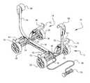
- FIG. 1is a perspective view of the adjustable container carriage of this invention, with snap on tie down clamps at the end of straps.
- FIG. 2is a perspective view of the carriage of FIG. 1 supporting an open container.
- FIG. 3is a broken partially sectional view of the axle housing, upright support frame and movable container platform.
- FIG. 4is a perspective view of the adjustable container carriage with alternate tie down straps.
- FIG. 5is a perspective view of the carriage of FIG. 4 supporting a closed container.
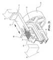
- FIG. 6is an exploded view of the carriage with a snow ski conversion assembly.
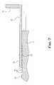
- FIG. 7is a cross sectional view along line 7 — 7 of FIG. 3 .
- FIG. 8is an exploded view of the front portion of the adjustable container carriage.
- the adjustable container carriage 10has a front wheel assembly 12 and a rear wheel assembly 14 connected together by a central connecting member 16 .
- the connecting member 16has a snap in engagement to a front axle housing 18 at its front end through opening 86 and to a rear axle housing 20 at its rear end at a like opening.
- Each axle housinghas a movable wheel at each end.
- Axle housing 18has a metal shaft 66 at each end on which wheels 22 and 24 turn.
- axle housing 20has metal shafts 66 at each end on which wheels 26 and 28 turn.
- the front axle housing 18is integral with a top surface of a right 30 and left 32 upright support frame and the rear axle housing 20 likewise is integral with a top surface of a right 34 and left 36 upright support frame.
- the adjustable container carriage 10has an open container 38 resting on four movable planar platforms 40 , 42 , 44 and 46 .
- a pliable rope 48 with a handle 50is used to pull the carriage and container.
- the rope 48 bottom endis engaged through opening 84 in axle housing 18 .
- the rope 48could be substituted with a rod or other similar device for pushing or pulling the carriage 10 .
- Straps 52 and 54are connected at a bottom slot 82 to axle housing 18 and 20 , respectively.
- a top of each strap 52 and 54has a clamp 56 and 58 , respectively for holding the container 38 in place when the straps 52 and 54 are tightened.
- the mechanism for widening or narrowing the platform for receipt of the container 38is shown in FIGS. 3 and 7 .
- the upright frame 32is integral with a top surface of axle housing 18 .
- a top surface 60 of frame 32has multiple ridges 62 perpendicular to the axle housing 18 .
- the top surface 60has side edges 64 which slide in C-channels 65 on each side of a planar platform 42 so that platform 42 can move inwardly or outwardly.
- the platform 42has a latch 68 with a bottom surface having a spike 63 corresponding to and engaging between ridges 62 . By lifting latch 68 , the ridges 62 and spike 63 disengage so platform 42 can move inwardly or outwardly to accommodate the width of container 38 .
- Upright walls 70 integral with platforms 40 , 42 , 44 and 46act as a stop to prevent a container from moving sideways off the carriage 10 .
- alternate means for connecting straps 52 and 54can be used.
- Female connector 72accepts male connector 74 to fixedly attach the ends of straps 52 and 54 .
- Other connectorscan be employed in like manner.
- Containerscan assume many shapes and can be open as shown in FIG. 2 for container 38 or closed as shown in FIG. 5 for container 76 .
- Right ski 78 or left ski 80can be attached to wheels 22 / 26 and 24 / 28 , respectively to use carriage 10 in snow or on ice.
- the front wheel assembly 12 , the rear wheel assembly 14 , the central connecting member 16 , the wheels 22 , 24 , 26 and 28 , and the movable planar platforms 40 , 42 , 44 and 46are all disengageable for compact storage. They are made of a high strength polymer.
Landscapes
- Engineering & Computer Science (AREA)
- Chemical & Material Sciences (AREA)
- Combustion & Propulsion (AREA)
- Transportation (AREA)
- Mechanical Engineering (AREA)
- Handcart (AREA)
Abstract
Description
This invention relates to a mobile container carriage. More specifically, it refers to a four wheeled mobile carriage for supporting containers of various dimensions.
Container carriages or dollies are common devices for assisting in moving large, heavy loads as seen by descriptions in many prior art references. In addition, U.S. Pat. No. 4,166,638 and 4,545,592 describe carriages that are adjustable in length and width to accommodate loads of different dimensions. Such adjustable carriages are more versatile and more desirable. However, the prior art adjustable devices are cumbersome and time consuming to adjust, particularly for different widths as shown in U.S. Pat. No. 4,545,592.
An adjustable carriage is needed which can be easily narrowed or widened to accommodate different containers.
The present invention solves the prior art problem by providing an adjustable carriage that can be either narrowed or widened by the flick of a latch and can be disassembled for storage. The invention is a carriage having a fixed front and rear wheel assembly connected by a central connecting member. Each wheel assembly has an axle housing with a rotating wheel at each end. An upright support frame rests on the top of each end portion of the axle housings between the central connecting member and the wheel. The support frames have engagement ridges on a top surface and side edges for engagement with a slidable planar platform. A complimentary spike on a bottom surface of the planar platform engages the ridges to lock the platform in position until a latch at an inboard end of the planar platform is lifted to disengage the spike and allow the platform to move to or away from the central connecting member and thereby narrow or widen the carriage.
The invention can be best understood by those having ordinary skill in the art by reference to the following detailed description when considered in conjunction with the accompanying drawings in which:
Throughout the following description, the same reference numerals refer to the same elements in all figures.
Referring toFIG. 1 , theadjustable container carriage 10 has afront wheel assembly 12 and arear wheel assembly 14 connected together by a central connectingmember 16. The connectingmember 16 has a snap in engagement to afront axle housing 18 at its front end through opening86 and to arear axle housing 20 at its rear end at a like opening. Each axle housing has a movable wheel at each end. Axlehousing 18 has ametal shaft 66 at each end on whichwheels axle housing 20 hasmetal shafts 66 at each end on whichwheels front axle housing 18 is integral with a top surface of a right30 and left32 upright support frame and therear axle housing 20 likewise is integral with a top surface of a right34 and left36 upright support frame.
Referring toFIG. 2 , theadjustable container carriage 10 has anopen container 38 resting on four movableplanar platforms pliable rope 48 with ahandle 50 is used to pull the carriage and container. Therope 48 bottom end is engaged through opening84 inaxle housing 18. Alternatively, therope 48 could be substituted with a rod or other similar device for pushing or pulling thecarriage 10.Straps bottom slot 82 toaxle housing strap clamp container 38 in place when thestraps
The mechanism for widening or narrowing the platform for receipt of thecontainer 38 is shown inFIGS. 3 and 7 . Theupright frame 32 is integral with a top surface ofaxle housing 18. Atop surface 60 offrame 32 hasmultiple ridges 62 perpendicular to theaxle housing 18. In addition, thetop surface 60 hasside edges 64 which slide in C-channels 65 on each side of aplanar platform 42 so thatplatform 42 can move inwardly or outwardly. Theplatform 42 has alatch 68 with a bottom surface having aspike 63 corresponding to and engaging betweenridges 62. By liftinglatch 68, theridges 62 andspike 63 disengage soplatform 42 can move inwardly or outwardly to accommodate the width ofcontainer 38.Upright walls 70 integral withplatforms carriage 10.
As shown inFIGS. 4 and 5 , alternate means for connectingstraps Female connector 72 acceptsmale connector 74 to fixedly attach the ends ofstraps FIG. 2 forcontainer 38 or closed as shown inFIG. 5 forcontainer 76.
Thefront wheel assembly 12, therear wheel assembly 14, the central connectingmember 16, thewheels planar platforms
Equivalent elements can be substituted for the elements ofcarriage 10 to provide substantially the same result, in substantially the way to achieve substantially the same function.
Claims (16)
1. An adjustable width carriage for supporting and carrying containers of varying widths, the carriage comprising:
a front and rear wheel assembly connected by a central connecting member;
the front and rear wheel assemblies each having an axle housing having a shaft at a first and second end with a wheel rotating on the shaft at the first and second end;
a right side upright support frame affixed to a top surface of the axle housing between the central connecting member and the first end of the axle housing and a left side upright support frame affixed to the axle housing between the central connecting member and the second end of the axle housing in the front and rear wheel assemblies;
the upright support frames each having on a top surface multiple engagement ridges, the top surface terminating in side edges adapted to engage oppositely positioned C-channels on a movable planar platform;
the movable planar platform having a top and bottom surface, the platform slidably mounted along the side edges of the support frame; and
a latch portion of the platform having a bottom surface with an engagement spike complimentary to the engagement ridges on the top surface of the upright support frame so that upon lifting of the latch the spike disengages from the engagement ridges and movement of the planar platforms can be achieved by sliding the planar platforms in or out with respect to the central connecting member to accommodate containers of different widths resting on a top surface of the planar platform.
2. An adjustable width carriage according toclaim 1 wherein the central connecting member has a front portion snapping into an opening in the front axle housing and a rear portion snapping into an opening in the rear axle housing.
3. An adjustable width carriage according toclaim 1 wherein a rope is attached through a bore in the front wheel assembly for pulling the carriage.
4. An adjustable width carriage according toclaim 1 wherein an open container is mounted on the planar platforms.
5. An adjustable width carriage according toclaim 4 wherein the open container is held in place by a pair of U-clamps, each affixed to a strap, the strap attached distally from the U-clamp to the wheel assembly.
6. An adjustable width carriage according toclaim 4 wherein the planar platforms have an upright wall at an outboard end to prevent sideways movement of the container.
7. An adjustable width carriage according toclaim 1 wherein a closed container is mounted on the planar platforms.
8. An adjustable width carriage according toclaim 7 wherein the closed container is held in place by a pair of straps, each attached at a bottom end to the front and rear wheel assemblies, respectively and engaged together at a top end by a male and female snap lock fastener.
9. A four wheeled carriage for supporting and carrying containers of varying widths, the carriage comprising:
a front and rear wheel assembly, each having an axle housing with a wheel rotating on a shaft at a first and second end of the axle housing;
a connecting member attached to a central portion of the front and rear wheel assemblies;
a right side upright support frame affixed to a top surface of the axle housing between the central connecting member and the first end of the axle housing and a left side upright support frame affixed to the axle housing between the connecting member and the second end of the axle housing on the front and rear wheel assemblies;
the upright support frames each having on a top surface multiple engagement ridges positioned to receive a spike on a bottom surface of a latch, the top surface terminating in side edges;
a movable planar platform having a top surface with the latch formed at an inboard end of the platform, C-channels formed on opposed inner sides of the planar platform to receive the side edges of the upright support frame top surface; and
the spike on the bottom surface of the latch portion of the platform normally contacting the engagement ridges on the top surface of the upright support frame, but upon lifting of the latch the spike is disengaged from the ridges and movement of the planar platform can be achieved by sliding the planar platform in or out with respect to the connecting member to accommodate containers of different width resting on a top surface of the planar platform.
10. A four wheeled carriage according toclaim 9 wherein the front portion of the connecting member snaps into a through bore in the front axle housing and the rear portion of the connecting member snaps into a through bore in the rear axle housing.
11. A four wheeled carriage according toclaim 9 wherein the right side upright support frame and left side upright support frame are integral with the respective axle housings.
12. A four wheeled carriage according toclaim 9 wherein the front and rear wheel assemblies, the connecting member, the wheels and the movable planar platform are disengageable for storage.
13. A four wheeled carriage according toclaim 9 wherein a pulling rope is attached to the front wheel assembly at a bottom end and to a handle at a top end.
14. A four wheeled carriage according toclaim 9 wherein a first and second container support strap is attached to the front and rear wheel assemblies, respectively at a bottom end and to a clamp at a top end.
15. An adjustable width carriage for supporting and carrying containers of varying widths, the carriage comprising:
a front and rear wheel assembly connected by a removable connecting member;
the front and rear wheel assemblies each having an axle housing with a shaft at a first and second end and a wheel rotating on the shaft at the first and second end;
a right and left side upright support frame integral with a top of the axle housing on both the front and rear wheel assemblies;
the upright support frames each having a top surface containing engagement ridges and a side surface on each side of the top surface adapted to receive a C-channel on opposite inner edges of a movable planar platform;
the movable planar platform having a top surface formed with a movable latch, the latch having a bottom projection adapted to engage the engagement ridges on the upright support frame in a resting position, but upon lifting the latch the planar platform is capable of moving inwardly or outwardly with respect to the upright support frame.
16. An adjustable width carriage according toclaim 15 wherein a pair of skis is attached to the right side and left side front and rear wheels, respectively to permit movement of the carriage on snow or ice.
Priority Applications (1)
| Application Number | Priority Date | Filing Date | Title |
|---|---|---|---|
| US10/816,111US6923468B1 (en) | 2004-04-01 | 2004-04-01 | Adjustable container carriage |
Applications Claiming Priority (1)
| Application Number | Priority Date | Filing Date | Title |
|---|---|---|---|
| US10/816,111US6923468B1 (en) | 2004-04-01 | 2004-04-01 | Adjustable container carriage |
Publications (1)
| Publication Number | Publication Date |
|---|---|
| US6923468B1true US6923468B1 (en) | 2005-08-02 |
Family
ID=34795865
Family Applications (1)
| Application Number | Title | Priority Date | Filing Date |
|---|---|---|---|
| US10/816,111Expired - Fee RelatedUS6923468B1 (en) | 2004-04-01 | 2004-04-01 | Adjustable container carriage |
Country Status (1)
| Country | Link |
|---|---|
| US (1) | US6923468B1 (en) |
Cited By (24)
| Publication number | Priority date | Publication date | Assignee | Title |
|---|---|---|---|---|
| US20070235968A1 (en)* | 2006-03-31 | 2007-10-11 | Krizan Dennis T | Adjustable monitor cart |
| US20080143150A1 (en)* | 2003-04-25 | 2008-06-19 | Snap-On Incorporated | Manually Actuated Brake System for Manually Towable Vehicle |
| US20090051143A1 (en)* | 2003-10-15 | 2009-02-26 | Darling Iii Charles W | Mission adaptable portable cart/utility table arrangement |
| US20100232927A1 (en)* | 2006-06-08 | 2010-09-16 | Frost Harlie D | Loading And Carting System |
| EP2305536A1 (en)* | 2009-10-02 | 2011-04-06 | N. Aarnoudse B.V. | Cart for transporting objects |
| US8123236B1 (en)* | 2010-02-12 | 2012-02-28 | James Helenihi | Universal cooler wheels |
| USD687615S1 (en)* | 2012-06-08 | 2013-08-06 | Nice Industries | Bar ends for camera dolly |
| US8628097B1 (en) | 2011-02-17 | 2014-01-14 | Theresa A. Elias | Transport system |
| US20150203141A1 (en)* | 2014-01-17 | 2015-07-23 | Daniel Todd Martin | Cooler Transporting Device |
| EP2570323A3 (en)* | 2011-09-13 | 2015-10-07 | Airbus Operations GmbH | Seat bank transport device |
| US20150360707A1 (en)* | 2013-02-06 | 2015-12-17 | Comau S.P.A. | Trolley for conveying containers for pieces or components in an industrial plant |
| US9550508B1 (en)* | 2015-09-25 | 2017-01-24 | Jose Parra | Non-rigid wheeled cart |
| US9637150B1 (en)* | 2013-06-27 | 2017-05-02 | Amazon Technologies, Inc. | Transport handle for low profile displacement |
| US20180201290A1 (en)* | 2017-01-19 | 2018-07-19 | Otter Products, Llc | Cart |
| US20190217877A1 (en)* | 2018-01-17 | 2019-07-18 | Daniel Robert Webber | Axially-expandable cooler cart and its method of use |
| EP3560794A1 (en)* | 2018-04-26 | 2019-10-30 | Marlin Steel Wire Products, LLC | Material handling device |
| US10543862B1 (en)* | 2019-08-28 | 2020-01-28 | Filemon Aguirre | Load-bearing assembly |
| USD890819S1 (en) | 2017-08-25 | 2020-07-21 | Daniel Robert Webber | Cooler cart |
| WO2020172626A1 (en)* | 2019-02-22 | 2020-08-27 | Santiva Outdoors, L.L.C. - Series IP | Adaptable modular attachment and accessory system for use with coolers, bait buckets and other containers |
| CN112298295A (en)* | 2020-11-15 | 2021-02-02 | 李昌平 | Mine hole is with preventing mud transport vechicle that outwards splashes |
| US11097763B1 (en)* | 2020-09-04 | 2021-08-24 | Doug Klassen | Sled for use in association with a waste container |
| US20230286560A1 (en)* | 2022-03-14 | 2023-09-14 | Inventor Gadgets, Llc | Bracket assembly for receiving axle |
| US11788650B1 (en) | 2019-02-22 | 2023-10-17 | Santiva Outdoors, L.L.C. | Outdoor apparatus |
| US20240359720A1 (en)* | 2021-12-08 | 2024-10-31 | Daniel Hanna | Expandable Dolly |
Citations (25)
| Publication number | Priority date | Publication date | Assignee | Title |
|---|---|---|---|---|
| US175259A (en) | 1876-03-28 | Improvement in sewing-machine casters | ||
| US1300533A (en)* | 1918-11-27 | 1919-04-15 | Lon Woodram Wessinger | Adjustable trunk-rack. |
| US2001894A (en) | 1934-06-02 | 1935-05-21 | Smith Arthur | Scrub bucket dolly |
| US2112155A (en) | 1936-01-09 | 1938-03-22 | Haney Mack | Garbage can holder |
| US2534367A (en)* | 1949-04-14 | 1950-12-19 | Edna M Perrotta | Load carrier |
| US3841650A (en) | 1973-06-25 | 1974-10-15 | R Miskelly | Luggage carrier |
| US3856322A (en) | 1970-05-15 | 1974-12-24 | U Bestehorn | Mobile packaging and stacking devices |
| US3874531A (en)* | 1974-03-21 | 1975-04-01 | William D Mayo | Cart and vehicular carrying system for the cart |
| US3964762A (en)* | 1974-07-22 | 1976-06-22 | Adams John F | Folding luggage carrier |
| US4166638A (en)* | 1978-04-25 | 1979-09-04 | Alfred De Prado | Adjustable dolly |
| US4313612A (en) | 1980-02-20 | 1982-02-02 | Rubens Robert A | Convertible trash container carrier |
| US4545592A (en)* | 1983-11-02 | 1985-10-08 | Boris Taskovic | Adjustable width luggage carrier apparatus |
| US5018930A (en)* | 1990-03-12 | 1991-05-28 | Sid Corp., Inc. | Lifting and transporting device |
| WO1993012964A1 (en)* | 1991-12-20 | 1993-07-08 | Michael Philip Hindle | A wheeled support |
| US5249823A (en)* | 1992-10-09 | 1993-10-05 | E.B.S. Equipment Services, Inc. | Size variable cart |
| US5299817A (en)* | 1992-06-09 | 1994-04-05 | Seth Chang | Adjustable mobile base |
| USD349994S (en)* | 1993-06-09 | 1994-08-23 | Tom Schurr | Container dolly |
| US5465996A (en)* | 1994-05-05 | 1995-11-14 | Wisz; William | Cooler carrier apparatus |
| US5599031A (en)* | 1995-02-22 | 1997-02-04 | Hodges; Douglas | Work dolly having adjustable height, width and length |
| US5826893A (en)* | 1996-08-02 | 1998-10-27 | Vega Enterprises, Inc. | Machinery mover |
| US5826670A (en)* | 1996-08-15 | 1998-10-27 | Nan; Huang Shun | Detachable propulsive device for wheelchair |
| US6203031B1 (en)* | 1998-12-07 | 2001-03-20 | Steelworks, Inc. | File cabinet dolly with open frame |
| US6382643B1 (en)* | 2000-09-11 | 2002-05-07 | Franklin W. Baker | Portable cross-framed dolly |
| US6783147B1 (en)* | 2002-08-21 | 2004-08-31 | Morris E. Green, Sr. | Cooler cart |
| US6786503B1 (en)* | 2002-05-31 | 2004-09-07 | Larry P. Young | Drywall cart |
- 2004
- 2004-04-01USUS10/816,111patent/US6923468B1/ennot_activeExpired - Fee Related
Patent Citations (25)
| Publication number | Priority date | Publication date | Assignee | Title |
|---|---|---|---|---|
| US175259A (en) | 1876-03-28 | Improvement in sewing-machine casters | ||
| US1300533A (en)* | 1918-11-27 | 1919-04-15 | Lon Woodram Wessinger | Adjustable trunk-rack. |
| US2001894A (en) | 1934-06-02 | 1935-05-21 | Smith Arthur | Scrub bucket dolly |
| US2112155A (en) | 1936-01-09 | 1938-03-22 | Haney Mack | Garbage can holder |
| US2534367A (en)* | 1949-04-14 | 1950-12-19 | Edna M Perrotta | Load carrier |
| US3856322A (en) | 1970-05-15 | 1974-12-24 | U Bestehorn | Mobile packaging and stacking devices |
| US3841650A (en) | 1973-06-25 | 1974-10-15 | R Miskelly | Luggage carrier |
| US3874531A (en)* | 1974-03-21 | 1975-04-01 | William D Mayo | Cart and vehicular carrying system for the cart |
| US3964762A (en)* | 1974-07-22 | 1976-06-22 | Adams John F | Folding luggage carrier |
| US4166638A (en)* | 1978-04-25 | 1979-09-04 | Alfred De Prado | Adjustable dolly |
| US4313612A (en) | 1980-02-20 | 1982-02-02 | Rubens Robert A | Convertible trash container carrier |
| US4545592A (en)* | 1983-11-02 | 1985-10-08 | Boris Taskovic | Adjustable width luggage carrier apparatus |
| US5018930A (en)* | 1990-03-12 | 1991-05-28 | Sid Corp., Inc. | Lifting and transporting device |
| WO1993012964A1 (en)* | 1991-12-20 | 1993-07-08 | Michael Philip Hindle | A wheeled support |
| US5299817A (en)* | 1992-06-09 | 1994-04-05 | Seth Chang | Adjustable mobile base |
| US5249823A (en)* | 1992-10-09 | 1993-10-05 | E.B.S. Equipment Services, Inc. | Size variable cart |
| USD349994S (en)* | 1993-06-09 | 1994-08-23 | Tom Schurr | Container dolly |
| US5465996A (en)* | 1994-05-05 | 1995-11-14 | Wisz; William | Cooler carrier apparatus |
| US5599031A (en)* | 1995-02-22 | 1997-02-04 | Hodges; Douglas | Work dolly having adjustable height, width and length |
| US5826893A (en)* | 1996-08-02 | 1998-10-27 | Vega Enterprises, Inc. | Machinery mover |
| US5826670A (en)* | 1996-08-15 | 1998-10-27 | Nan; Huang Shun | Detachable propulsive device for wheelchair |
| US6203031B1 (en)* | 1998-12-07 | 2001-03-20 | Steelworks, Inc. | File cabinet dolly with open frame |
| US6382643B1 (en)* | 2000-09-11 | 2002-05-07 | Franklin W. Baker | Portable cross-framed dolly |
| US6786503B1 (en)* | 2002-05-31 | 2004-09-07 | Larry P. Young | Drywall cart |
| US6783147B1 (en)* | 2002-08-21 | 2004-08-31 | Morris E. Green, Sr. | Cooler cart |
Cited By (32)
| Publication number | Priority date | Publication date | Assignee | Title |
|---|---|---|---|---|
| US20080143150A1 (en)* | 2003-04-25 | 2008-06-19 | Snap-On Incorporated | Manually Actuated Brake System for Manually Towable Vehicle |
| US7823906B2 (en)* | 2003-10-15 | 2010-11-02 | Valiant Rock LLC | Mission adaptable portable cart/utility table arrangement |
| US20090051143A1 (en)* | 2003-10-15 | 2009-02-26 | Darling Iii Charles W | Mission adaptable portable cart/utility table arrangement |
| US7419170B2 (en)* | 2006-03-31 | 2008-09-02 | Dennis Theodore Krizan | Adjustable monitor cart |
| US20070235968A1 (en)* | 2006-03-31 | 2007-10-11 | Krizan Dennis T | Adjustable monitor cart |
| US8500075B2 (en)* | 2006-06-08 | 2013-08-06 | Affinity Labs Of Texas, Llc | Loading and carting system |
| US20100232927A1 (en)* | 2006-06-08 | 2010-09-16 | Frost Harlie D | Loading And Carting System |
| EP2305536A1 (en)* | 2009-10-02 | 2011-04-06 | N. Aarnoudse B.V. | Cart for transporting objects |
| US8123236B1 (en)* | 2010-02-12 | 2012-02-28 | James Helenihi | Universal cooler wheels |
| US8628097B1 (en) | 2011-02-17 | 2014-01-14 | Theresa A. Elias | Transport system |
| EP2570323A3 (en)* | 2011-09-13 | 2015-10-07 | Airbus Operations GmbH | Seat bank transport device |
| USD687615S1 (en)* | 2012-06-08 | 2013-08-06 | Nice Industries | Bar ends for camera dolly |
| US20150360707A1 (en)* | 2013-02-06 | 2015-12-17 | Comau S.P.A. | Trolley for conveying containers for pieces or components in an industrial plant |
| US9694838B2 (en)* | 2013-02-06 | 2017-07-04 | Comau S.P.A. | Trolley for conveying containers for pieces or components in an industrial plant |
| US9637150B1 (en)* | 2013-06-27 | 2017-05-02 | Amazon Technologies, Inc. | Transport handle for low profile displacement |
| US9199657B2 (en)* | 2014-01-17 | 2015-12-01 | Daniel Todd Martin | Cooler transporting device |
| US20150203141A1 (en)* | 2014-01-17 | 2015-07-23 | Daniel Todd Martin | Cooler Transporting Device |
| US9550508B1 (en)* | 2015-09-25 | 2017-01-24 | Jose Parra | Non-rigid wheeled cart |
| US20180201290A1 (en)* | 2017-01-19 | 2018-07-19 | Otter Products, Llc | Cart |
| US10392043B2 (en)* | 2017-01-19 | 2019-08-27 | Otter Products, Llc | Cart |
| USD890819S1 (en) | 2017-08-25 | 2020-07-21 | Daniel Robert Webber | Cooler cart |
| US10633009B2 (en)* | 2018-01-17 | 2020-04-28 | Daniel Robert Webber | Axially-expandable cooler cart and its method of use |
| US20190217877A1 (en)* | 2018-01-17 | 2019-07-18 | Daniel Robert Webber | Axially-expandable cooler cart and its method of use |
| EP3560794A1 (en)* | 2018-04-26 | 2019-10-30 | Marlin Steel Wire Products, LLC | Material handling device |
| WO2020172626A1 (en)* | 2019-02-22 | 2020-08-27 | Santiva Outdoors, L.L.C. - Series IP | Adaptable modular attachment and accessory system for use with coolers, bait buckets and other containers |
| US11008030B2 (en) | 2019-02-22 | 2021-05-18 | Santiva Outdoors, L.L.C.—Series Ip | Adaptable modular attachment and accessory system for use with coolers, bait buckets and other containers |
| US11788650B1 (en) | 2019-02-22 | 2023-10-17 | Santiva Outdoors, L.L.C. | Outdoor apparatus |
| US10543862B1 (en)* | 2019-08-28 | 2020-01-28 | Filemon Aguirre | Load-bearing assembly |
| US11097763B1 (en)* | 2020-09-04 | 2021-08-24 | Doug Klassen | Sled for use in association with a waste container |
| CN112298295A (en)* | 2020-11-15 | 2021-02-02 | 李昌平 | Mine hole is with preventing mud transport vechicle that outwards splashes |
| US20240359720A1 (en)* | 2021-12-08 | 2024-10-31 | Daniel Hanna | Expandable Dolly |
| US20230286560A1 (en)* | 2022-03-14 | 2023-09-14 | Inventor Gadgets, Llc | Bracket assembly for receiving axle |
Similar Documents
| Publication | Publication Date | Title |
|---|---|---|
| US6923468B1 (en) | Adjustable container carriage | |
| US8251379B2 (en) | Apparatus for transport of objects | |
| US8651500B2 (en) | Dolly transport systems | |
| US9463675B2 (en) | Dolly | |
| US8070181B2 (en) | Convertible cart | |
| US9199657B2 (en) | Cooler transporting device | |
| US5797617A (en) | Luggage system and folding dolly therefor | |
| US20070194560A1 (en) | Foldable cart | |
| US9365225B2 (en) | Transformative hand cart | |
| US20080100076A1 (en) | Cargo carrying system | |
| US8141888B1 (en) | Surfboard transportation device | |
| US4052079A (en) | Wheelbarrow transport means | |
| US11643125B2 (en) | Dolly for attachment to a vehicle hitch | |
| US4275894A (en) | Hand truck construction assembly | |
| EP0688711A2 (en) | Two-wheeled trolley with vertical frame and a loadbearing platform | |
| JPH06199242A (en) | Dolly having platform provided with push grip | |
| US7407171B2 (en) | Compact cart | |
| JPH082753B2 (en) | Foldable two-wheeled wheelbarrow | |
| US20170029004A1 (en) | Transport Dollies | |
| US9108653B2 (en) | Adaptive wheeled carrier and transport device | |
| US7578721B1 (en) | Wheelie bar apparatus for a model vehicle | |
| US20170173444A1 (en) | Collapsible Ski Caddy | |
| US20110274526A1 (en) | Dock dolly | |
| US7093840B2 (en) | Multi-purpose combined ladder/cart assembly | |
| DE102018204723A1 (en) | Passenger car with receiving device for goods containers of a shopping cart |
Legal Events
| Date | Code | Title | Description |
|---|---|---|---|
| FPAY | Fee payment | Year of fee payment:4 | |
| REMI | Maintenance fee reminder mailed | ||
| LAPS | Lapse for failure to pay maintenance fees | ||
| STCH | Information on status: patent discontinuation | Free format text:PATENT EXPIRED DUE TO NONPAYMENT OF MAINTENANCE FEES UNDER 37 CFR 1.362 | |
| FP | Lapsed due to failure to pay maintenance fee | Effective date:20130802 |