US6922821B1 - System and a method for checking lock step consistency between an in circuit emulation and a microcontroller while debugging process is in progress - Google Patents
System and a method for checking lock step consistency between an in circuit emulation and a microcontroller while debugging process is in progressDownload PDFInfo
- Publication number
- US6922821B1 US6922821B1US09/998,859US99885901AUS6922821B1US 6922821 B1US6922821 B1US 6922821B1US 99885901 AUS99885901 AUS 99885901AUS 6922821 B1US6922821 B1US 6922821B1
- Authority
- US
- United States
- Prior art keywords
- microcontroller
- ice
- code
- execution
- lock
- Prior art date
- Legal status (The legal status is an assumption and is not a legal conclusion. Google has not performed a legal analysis and makes no representation as to the accuracy of the status listed.)
- Expired - Lifetime, expires
Links
Images


Classifications
- G—PHYSICS
- G06—COMPUTING OR CALCULATING; COUNTING
- G06F—ELECTRIC DIGITAL DATA PROCESSING
- G06F11/00—Error detection; Error correction; Monitoring
- G06F11/22—Detection or location of defective computer hardware by testing during standby operation or during idle time, e.g. start-up testing
- G06F11/26—Functional testing
- G06F11/261—Functional testing by simulating additional hardware, e.g. fault simulation
Definitions
- This inventionrelates generally to the field of in circuit emulation (ICE). More specifically an embodiment of the present invention relates to a method and system for “lock step” consistency checking between an ICE and a production microcontroller while debugging of a microcontroller code is in progress.
- ICEin circuit emulation
- circuit emulationIn circuit emulation (ICE) has been used by software and hardware developers for a number of years as a development tool to emulate the operation of complex circuit building blocks and permit diagnosis and debugging of hardware and software.
- ICEcircuit emulation
- Such in circuit emulationis most commonly used to analyze and debug the behavior of complex devices such as microcontrollers and microprocessors that have internal structures that are far too complex to readily model using computer simulation software alone.
- FIG. 1illustrates an exemplary conventional in-circuit emulation arrangement 100 used to model, analyze and debug the operation of a microcontroller device.
- a host computere.g., a personal computer
- a debug logic 120which is further connected to a special version of the microcontroller device that has been developed specially for use in emulation.
- a microcontroller manufacturerwould manufacture two versions of any one of its microcontrollers, a special version and a production version.
- the special version of the microcontrollerincludes special testing hardware (e.g., scan chain, registers, and the like) for supporting software debugging functions.
- the special versionis only used for the purpose of testing and debugging microcontroller code, where the debugged microcontroller code is eventually loaded in the production version of the same microcontroller to be marketed.
- Debugging operationstarts with the host computer 110 loading instructions through debug logic block 120 to the special version of the microcontroller 130 where the instructions are executed. Depending upon the application, this operation may be monitored while the special version of the microcontroller 130 is interconnected with the circuitry that is intended to interface a production version of the microcontroller in the finished product under development. Such interconnection -may be via simulation within the host computer 110 or as actual circuitry or some combination thereof. As the circuit is stepped through its operation, the debug logic gathers information about the state of various components of the microcontroller 130 during operation and feeds that information back to the host computer 110 for analysis.
- various trace informationsuch as time stamps, register value, data memory content, etc.
- various break pointscan be defined by the designer that cause the program to halt execution at various points in the operation to permit detailed analysis.
- Other debugging toolsmay also be provided to enable the user to debug the operation of the circuit.
- a microcontrolleris installed in a test circuit, which closely resembles the hardware that is to be controlled by the production version of the microcontroller under the test. It is appreciated that the term base station and ICE are used interchangeably herein.
- ICEis a conventional technique for debugging a microcontroller code.
- a typical ICEincludes a production microcontroller used for debugging purposes, a virtual copy of the production microcontroller, which exist in the base station unit, and a host device.
- the production microcontrollerincludes a memory, a CPU register, a SRAM, a program counter, and a file register.
- the host devicecopies a substantial part of the production microcontroller in the base station, which forms the virtual microcontroller.
- the base stationalso includes a memory, a CPU register, a SRAM, a program counter, and a file register.
- Debugging processis initiated by software residing in the host device, which loads the microcontroller code in both production microcontroller and the virtual microcontroller.
- the Production microcontroller and the virtual microcontrollerrun the microcontroller code in a synchronized process. Synchronization of the microcontroller and the virtual microcontroller requires that the production microcontroller and the virtual microcontroller start running the microcontroller code at the same time, execute the same lines of code sequentially, and if there is a breakpoint in the microcontroller code or if a user halts the execution of the microcontroller code for any purpose, both production and virtual microcontroller encounter the command at the same time.
- synchronizationrequires that during the course of debugging the microcontroller code, after execution of each line of the microcontroller code, the memory, the CPU register, and SRAM of the virtual microcontroller and the memory, the CPU register, and SRAM of the production microcontroller have the same value. Furthermore, it is appreciated that the contents of the memory, the CPU register, and SRAM in the production microcontroller are not available to the user while the production microcontroller is executing a code.
- An embodiment of the present inventionprovides a user with capability to conduct a lock step consistency check while a debugging process of a microcontroller code is in progress.
- One embodiment of the present inventionprovides a host device to copy a production microcontroller, residing on a test circuit, into an in circuit emulation (ICE) system to provide a virtual memory.
- Another embodiment of the present inventionprovides the host device to load a microcontroller code comprising of a plurality of lines of code in the production microcontroller and in the virtual microcontroller.
- the production microcontroller and the virtual microcontrollerexecute a line of code of the plurality of lines of code synchronously in accordance with a lock-step process.
- a register in the virtual microcontrollerretains a first value and a register in the production microcontroller retains a second value.
- the first value and the second valueare the result of synchronous execution of the line of code in the production microcontroller and in the virtual microcontroller respectively.
- An embodiment of the present inventionprovides the ICE to receive the first value and compare the first value with the second value.
- One embodiment of the present inventionprovides the ICE to halt the debugging process and to issue a “lock-step error”, if the comparison of the first value and the second value results in a mismatch.
- a userrefers to a trace buffer residing in the ICE and identifies the line of code, which caused the “lock-step error” and debugs the line of code accordingly.
- ICEdoes not have access to any data communicated between the test circuit (e.g., a peripheral) and the production microcontroller.
- the production microcontrollerinforms the ICE when it receives data from the.
- a system and a method for debugging a microcontroller code while debugging processis in progress.
- a line of code of a plurality of lines of codeis executed by a production microcontroller producing a first value.
- the line of code of the plurality of lines of codeis synchronously executed by an ICE and producing the second value.
- the first valueis sent to the ICE.
- ICEcompares the first value and the second value and if the result of the comparison is a mismatch it issues a “lock-step error”.
- a “lock step error”issues, a user traces a trace buffer, residing in the ICE, and locates the line of code causing the mismatch and debugs the faulty line of code.
- FIG. 1is a block diagram of a conventional in circuit emulator (ICE).
- ICEin circuit emulator
- FIG. 2is a block diagram of an exemplary in circuit emulation system consistent with certain microcontroller embodiments of the present invention.
- FIG. 3is an illustration of checking the consistency of lock step execution of a debugging process at a halt state.
- these quantitiestake the form of electrical or magnetic signals capable of being stored, transferred, combined, compared, and otherwise manipulated in a computer system. It has proven convenient at times, principally for reasons of common usage, to refer to these signals as bits, values, elements, symbols, characters, terms, numbers, or the like.
- a commercial ICE system utilizing the present inventionis available from Cypress MicroSystems, Inc., for the CY8C25xxx/26xxx series of microcontrollers. Detailed information regarding this commercial product is available from Cypress MicroSystems, Inc., 22027 17th Avenue SE, Suite 201, Bothell, Wash. 98021, in the form of version 1.11 of “PSOC DESIGNER: Integrated Development Environment User Guide”, which is hereby incorporated by reference. While the present invention is described in terms of an ICE system for the above exemplary microcontroller device, the invention is equally applicable to other complex circuitry including microprocessor and other circuitry that is suitable for analysis and debugging using in-circuit emulation. Moreover, the invention is not limited to the exact implementation details of the exemplary embodiment used herein for illustrative purposes.
- a host computer 210e.g., a personal computer based on a PENTIUM® class microprocessor
- a standard PC interface 214such as a parallel printer port connection, a universal serial port (USB) connection, etc.
- the host computer 210generally operates to run an ICE computer program to control the emulation process and further operates in the capacity of a logic analyzer to permit a user to view information provided from the base station 218 for use in analyzing and debugging a device under test or development.
- the device under test 232mounted on pod 250 , comprises file register 236 , SRAM 237 , CPU 238 , program counter 239 , and a memory 240.
- the base station 218is based upon a general purpose programmable hardware device such as a gate array configured to function as a functionally equivalent “virtual microcontroller” 220 (or other device under test (DUT)). This is accomplished using an associated integral memory 222 which stores program instructions, data, and other associated information. Base station 218 further including file register 221 , program counter 223 , CPU 224 , and SRAM 225 . The base station 218 is configured as an emulator of the internal microprocessor portion of the microcontroller 232 . In preferred embodiments, a field programmable gate array FPGA (or other programmable logic device) is configured to function as the virtual microcontroller 220 .
- the FPGA and virtual microcontroller 220will be referred to interchangeably herein.
- the base station 218further includes a trace buffer 226 , which stores trace path of the microcontroller code, is coupled (e.g., using a four wire interface 227 ) to a production microcontroller 232 mounted in a mounting device referred to as a pod 250 .
- Pod 250in certain embodiments, provides connection to the microcontroller 232 that permit external probing as well as interconnection with other circuitry as might be used to simulate a system under development.
- the FPGA of the base station 218 of the current embodimentis designed to emulate the core processor functionality (microprocessor functions, Arithmetic Logic Unit functions, RAM, and ROM memory functions) of the Cypress MicroSystems CY8C25xxx/26xxx series microcontrollers.
- the CY8C25xxx/26xxx series of microcontrollersalso incorporate limited I/O functions and an interrupt controller as well as programmable digital and analog circuitry. This circuitry need not be modeled using the FPGA 220 . Instead the I/O read information, interrupt vector and other information can be passed to the FPGA 220 from the microprocessor 232 via interface 227 as will be described later.
- the base station 218 's virtual microcontroller 220operates to execute the code programmed into the microcontroller 232 in lock-step operation with the microcontroller 232 .
- the actual microprocessor 232is freed of any need to provide significant special facilities for ICE, since any such facilities can be provided in the virtual microcontroller 220 .
- the base station 218 's virtual microcontroller 220 and microcontroller 232execute all steps of the program under test and in lock step without a need to communicate except when a break point or a halt state is encountered.
- the combination of production and virtual microcontrollerbehaves just as the microcontroller 232 would alone under normal operation conditions.
- I/O reads and interrupts vectorsare transferred from the microcontroller 232 to the base station 218 .
- Base station 218is then able to provide the host computer 210 with the I/O reads and interrupts vectors as well as an array of information internal to the microcontroller 232 within memory and register locations that are otherwise inaccessible.
- VERILOG® languageor other suitable language
- the base station 218 of the current embodimentis based upon the commercially available SPARTAN® series of FPGAs from Xilinx, Inc., 2100 Logic Drive, San Jose, Calif. 95124.
- the VERILOG® descriptioncan be used as the input to the FPGA design and synthesis tool available from the FPGA manufacturer to realize the virtual microcontroller 220 (generally after timing adjustments and other debugging).
- the actual production microcontroller 232carries out its normal functions in the intended application and passes I/O information and other information needed for debugging to the base station 218 only at a break point or when in halt state.
- the virtual microcontroller 220 implemented within the FPGA of base station 218serves to provide the operator with visibility into the core processor functions that are inaccessible in the production microcontroller 232 .
- the FPGAby virtue of operating in lock-step operation with the microprocessor 232 provides an exact duplicate of internal registers, memory contents, interrupt vectors and other useful debug information.
- trace buffer 226can be used to store information useful in trace operations that is gathered by the FPGA during execution of the program under test. This architecture, therefore, permits the operator to have visibility into the inner working of the microcontroller 232 without need to provide special boundouts and expensive circuitry on the microcontroller itself.
- the base station 218 's FPGA based virtual microcontroller 220operating under control of host computer 210 , carries out the core processor function of microcontroller 232 and thus contains a functionally exact emulated copy of the contents of the registers and memory of the production microcontroller 232 .
- the ICE system 200starts both microcontrollers (production 232 and virtual 220 ) at the same time and keeps them running in synchronization. Whenever the system is halted (i.e., when the system is not emulating), or when system encounters a breakpoint (e.g., sleep, stall, internal start/stop, stalls, etc.) a consistency check may be conducted.
- a breakpointe.g., sleep, stall, internal start/stop, stalls, etc.
- execution of a microcontroller code in the base station 218is a mirror,image of the execution of the microcontroller code is the production microcontroller 232 .
- the content of registers in production microcontroller 232 and base station 218are not the same.
- the software residing in base station 218performs a consistency check.
- Base station 218verifies the integrity of the lock step process by comparing the contents of the registers in base station 218 and the content of registers in production computer 232 . In case of a mismatch between the contents of base station registers and the content of production microcontroller registers, the software residing in base station 218 halts the execution of the microcontroller code and issues a signal indicating a “lock step error”.
- Another embodiment of the present inventionprovides a consistency check when a breakpoint is encountered.
- the virtual microcontroller microcontroller 220 and production microcontroller 232run a microcontroller code in accordance with a lock-step process. Therefore, both microcontrollers start running at the same time, run the same line of code and stop at the same line of code when encountering a breakpoint. Accordingly, the content of their memory and registers should be the same during the execution of the microcontroller code.
- a usercan locate the line of code, causing the inconsistency, and investigate the reason for the mismatch. The user can locate the erroneous line of code by referring to the trace buffer and once the erroneous code is identified the use can debug the line of code accordingly.
- lock step processrequires that at any instant virtual microcontroller 220 and production microcontroller 232 execute the same line of code and thus the contents of their registers should hold the same value.
- production microcontrolleradds “1” to the content of its accumulator and sends the result of the operation to base station 218 .
- Base station 218compares the content of the accumulator received from production microcontroller 232 against the content of its own accumulator. When the result of the comparison is a mismatch, the software in the base station 218 halts the debugging process and issues a “lock step error”.
- base station 218does not share the same information with production microcontroller 232 .
- the first instanceis when production microcontroller receive an I/O data from the test circuit, or the circuit which under normal operation production controller is to control and would receive I/O information.
- the second instanceis when an outside event causes an interrupt in the operation of the production microcontroller. Under these two circumstances, base station 218 will perform the next line of code and conducts the comparison on the next line of instruction.
- the userchecks the trace buffer 226 .
- the trace buffer 226keeps track of each line of codes executed and resides in the base station 218 . Examining trace buffer 226 the user can determines which line of code caused the halt. Trace buffer also keeps track of the content of CPU registers on each line of code. The user can back track the execution of each line of code and the associated CPU registers to find the exact line of code where the content of CPU register 238 and the content of CPU register 234 diverge as a result of a faulty code. Once the code is debugged the debugging process will resume. It is appreciated that both CPU register and SRAM on base station 218 and standard microcontroller 232 are initialized with zeros to ensure the integrity of the tracing and the consistency checking.
- a lock step consistency checkmay be conducted.
- the lock-step operation of the microcontroller 232 and the virtual microcontroller 220requires the virtual microcontroller 220 and standard microcontroller 232 to start running a microcontroller code at the same time, run each line of the microcontroller code at the same time, have the same CPU register content and the same SRAM content on both sides, and to stop at the exactly the same line of code when a breakpoint is encountered. Therefore, at a breakpoint the software in the host device 210 will conduct a consistency check as described above and if there is a mismatch of memory content or SRAM content the host device 210 will issue a “lock step error”.
- the basic interface usedis a four line interface between microcontroller 232 and base station 218 .
- This interfacepermits use of a standard five wires Category Five patch cable to connect the microcontroller 232 and base station 218
- the four wire interface 227 of the present embodimentcan be functionally divided into two functional portions.
- a data transport portion 242carries two data lines in the current embodiment.
- a clock portion 246carries a data clock plus the microcontroller clock signal for the microcontroller 232 .
- Three additional linesare also provided (not shown) for supply, ground and reset line. But, the data transport portion 242 and the clock portion 246 are of primary interest, since the supply and reset functions can be readily provided in any other suitable manner.
- the two portions of the interfaceare implemented in the current embodiment using four lines as described, however, in other embodiments, these two portions can be implemented with as few as two wires.
- the microcontroller clock signalcan be varied by programming (even dynamically during execution of a program). Therefore, it is desirable to have two clock signals-microcontroller clock to easily track the microcontroller clock timing as well a system clock that regulates the data transfer and other operations.
- a single clockcan be used. The single clock can be multiplied or divided as required to implement the required clocking signal.
- the present embodimentuses an eight-bit microcontroller that only reads eight bits at a time on any given I/O read.
- the present microcontroller 232needs only to effect serializing and transferring a maximum of one eight bit I/O read for each instruction cycle. This is easily accommodated using two data lines transferring four bits each over four system clock cycles. However, using a clock, which is two times faster, a single line could equally well transfer the data in the same time. Similarly, four lines could be used to transfer the same data in a short enough time to permit the virtual microcontroller 220 to process the data and issue any needed response before the next instruction cycle begins. The time required to accomplish this is held at a minimum in the current invention, since the system synchronization eliminates need for any overhead protocol for transmission of the data.
- the present embodimentuses a four line communication interface and method of communication between the FPGA within base station 218 (acting as a “virtual microcontroller” 220 or ICE) and the production microcontroller device under test (microcontroller 232 ).
- the four line communication interfaceis time-dependent so that different information can be transferred at different times over a small number of communication lines.
- This interfaceis used for, among other things, transferring of I/O data from the microcontroller 232 to the FPGA 220 (since FPGA emulates only the core processor functions of the microcontroller in the current embodiment).
- a first interface line(data 1 ) is a data line used by the microcontroller 232 to send I/O data to FPGA based virtual microcontroller 220 . This line is also used to notify the FPGA 220 of pending interrupts. This data 1 line is only driven by the production microcontroller 232 .
- a second data line(Data 2 ), which is bi-directional, is used by the microcontroller 232 to send I/O data to FPGA based virtual microcontroller of base station 218 .
- the FPGA 220uses the Data 2 line to convey halt requests (i.e., to implement simple or complex breakpoints) to the microcontroller 232 .
- a third interface lineis a 24/48 Mhz data clock used to drive the virtual microcontroller 220 's communication state machines (the logic used within the state controller to communicate with the microcontroller 232 ). In the current embodiment, this clock always runs at 24 Mhz unless the microcontroller 232 's internal clock is running at 24 Mhz. In this case the system clock switches to 48 Mhz. Of course, these exact clock speeds are not to be considered limiting, but are presented as illustrative of the current exemplary embodiment.
- the fourth interface lineis the internal microcontroller clock from the microcontroller 232 .
- a fifth linecan be used to provide a system reset signal to effect the simultaneous startup of both microcontrollers.
- This fifth lineprovides a convenient mechanism to reset the microcontrollers, but in most environments, the simultaneous startup can also be effected in other ways including switching of power.
- Sixth and seventh linesare provided in the current interface to provide power and ground for power supply
- the base station 218 's virtual microcontroller 220communicates with the microcontroller 232 via four signal and clock lines forming a part of the four line interface 227 forming a part of a seven wire connection as described below.
- the interface signalstravel over a short (e.g., one foot) of CAT 5 network cable.
- the ICEtransmits break commands to the microcontroller 232 via the base station 218 , along with register read/write command when the microcontroller 232 is halted.
- the microcontroller 232uses the interface to return register information when halted, and to send I/O read, interrupt, vector, and watchdog information while running.
- the microcontroller 232also sends a copy of its internal clocks for the ICE.
- Synchronization between the microcontroller 232 and the virtual microcontroller 220is achieved by virtue of their virtually identical operation. They are both started simultaneously by a power on or reset signal. They then track each other's operation continuously executing the same instructions using the same clocking signals.
- the system clock signal and the microcontroller clock signalare shared between the two microcontrollers (production and virtual) so that even if the microprocessor clock is changed during operation, they remain in lock step.
- a mechanismfor allowing the FPGA 220 of base station 218 and the microcontroller 232 to stop at the same instruction in response to a break-point event (a break or halt).
- the FPGA 220has the ability to monitor the microcontroller states of microcontroller 232 for a breakpoint event, due to its lock-step operation with microcontroller 232 .
- an internal start of instruction cycle (SOI) signalis generated (by both microcontrollers) that indicates that the device is about to execute a next instruction. If a break point signal (a halt or break signal—the term “halt” and “break” are used synonymously herein) is generated by the FPGA, the execution of the microcontroller 232 can be stopped at the SOI signal point before the next instruction starts.
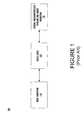
- FIG. 3is a flow chart of the steps of a microcontroller code debugging process 300 in accordance with one embodiment of the present invention. As depicted in FIG. 3 , process 300 shows the steps involved in debugging microcontroller code using a lock step execution ICE system (e.g., system 200 of FIG. 2 ).
- a lock step execution ICE systeme.g., system 200 of FIG. 2
- Process 300begins in step 301 where microcontroller program code is loaded into a target microcontroller and an ICE.
- the debugging processbegins by initializing a first memory of the ICE and a second memory of the microcontroller with microcontroller test code.
- This test codetypically comprises a microcontroller application requiring testing with multiple microcontroller configurations, settings, conditions, and the like.
- code executionsubsequently begins with the code being executed on both the microcontroller (e.g., the target microcontroller) and the ICE in lock step.
- the ICEcomputes the result of a current instruction (e.g., ADD, SUBTRACT, MOVE, etc.).
- the microcontrollercomputes the result of the current instruction and transmits the result to the ICE.
- step 305lock step execution of the microcontroller test code is verified by comparing the current instruction result from the ICE with the current instruction result received from the microcontroller. If the current instruction results match, lock step execution is verified and process 300 proceeds to step 307 . If the current instruction results do not match, lock step execution is not verified and process 300 proceeds to step 306 .
- step 307microcontroller code execution continues with the next line of code being executed and process 300 proceeding to step 303 .
- step 306where lock step execution is not verified, the ICE halts the execution and reports a lock step error.
- the usermay view an execution history of the most recently executed lines of code in a trace buffer to determine a cause of the error.
Landscapes
- Engineering & Computer Science (AREA)
- Computer Hardware Design (AREA)
- General Engineering & Computer Science (AREA)
- Theoretical Computer Science (AREA)
- Quality & Reliability (AREA)
- Physics & Mathematics (AREA)
- General Physics & Mathematics (AREA)
- Test And Diagnosis Of Digital Computers (AREA)
- Debugging And Monitoring (AREA)
Abstract
Description
Claims (25)
Priority Applications (1)
| Application Number | Priority Date | Filing Date | Title |
|---|---|---|---|
| US09/998,859US6922821B1 (en) | 2001-11-15 | 2001-11-15 | System and a method for checking lock step consistency between an in circuit emulation and a microcontroller while debugging process is in progress |
Applications Claiming Priority (1)
| Application Number | Priority Date | Filing Date | Title |
|---|---|---|---|
| US09/998,859US6922821B1 (en) | 2001-11-15 | 2001-11-15 | System and a method for checking lock step consistency between an in circuit emulation and a microcontroller while debugging process is in progress |
Publications (1)
| Publication Number | Publication Date |
|---|---|
| US6922821B1true US6922821B1 (en) | 2005-07-26 |
Family
ID=34750697
Family Applications (1)
| Application Number | Title | Priority Date | Filing Date |
|---|---|---|---|
| US09/998,859Expired - LifetimeUS6922821B1 (en) | 2001-11-15 | 2001-11-15 | System and a method for checking lock step consistency between an in circuit emulation and a microcontroller while debugging process is in progress |
Country Status (1)
| Country | Link |
|---|---|
| US (1) | US6922821B1 (en) |
Cited By (55)
| Publication number | Priority date | Publication date | Assignee | Title |
|---|---|---|---|---|
| US20030237023A1 (en)* | 2002-06-25 | 2003-12-25 | Fujitsu Limited | Associated apparatus and method for supporting development of semiconductor device |
| US7076420B1 (en)* | 2000-10-26 | 2006-07-11 | Cypress Semiconductor Corp. | Emulator chip/board architecture and interface |
| US7162410B1 (en)* | 2000-10-26 | 2007-01-09 | Cypress Semiconductor Corporation | In-circuit emulator with gatekeeper for watchdog timer |
| US20070294055A1 (en)* | 2006-06-16 | 2007-12-20 | Via Technologies, Inc. | Debug device for detecting bus transmission and method thereof |
| US7346481B1 (en)* | 2004-08-31 | 2008-03-18 | Xilinx, Inc. | Hardware co-simulation breakpoints in a high-level modeling system |
| US20080244534A1 (en)* | 2002-11-06 | 2008-10-02 | Valery Golender | System and method for troubleshooting software configuration problems using application tracing |
| US7526422B1 (en) | 2001-11-13 | 2009-04-28 | Cypress Semiconductor Corporation | System and a method for checking lock-step consistency between an in circuit emulation and a microcontroller |
| US20090204384A1 (en)* | 2008-02-12 | 2009-08-13 | Kabushiki Kaisha Toshiba | Debugging device, debugging method and hardware emulator |
| US7737724B2 (en) | 2007-04-17 | 2010-06-15 | Cypress Semiconductor Corporation | Universal digital block interconnection and channel routing |
| US7761845B1 (en) | 2002-09-09 | 2010-07-20 | Cypress Semiconductor Corporation | Method for parameterizing a user module |
| US7765095B1 (en) | 2000-10-26 | 2010-07-27 | Cypress Semiconductor Corporation | Conditional branching in an in-circuit emulation system |
| US20100191941A1 (en)* | 2009-01-29 | 2010-07-29 | Nec Electronics Corporation | Failure analysis apparatus, method |
| US7770113B1 (en) | 2001-11-19 | 2010-08-03 | Cypress Semiconductor Corporation | System and method for dynamically generating a configuration datasheet |
| US7774190B1 (en)* | 2001-11-19 | 2010-08-10 | Cypress Semiconductor Corporation | Sleep and stall in an in-circuit emulation system |
| US20100228918A1 (en)* | 1999-06-10 | 2010-09-09 | Martin Vorbach | Configurable logic integrated circuit having a multidimensional structure of configurable elements |
| US7825688B1 (en) | 2000-10-26 | 2010-11-02 | Cypress Semiconductor Corporation | Programmable microcontroller architecture(mixed analog/digital) |
| US7844437B1 (en) | 2001-11-19 | 2010-11-30 | Cypress Semiconductor Corporation | System and method for performing next placements and pruning of disallowed placements for programming an integrated circuit |
| US7893724B2 (en) | 2004-03-25 | 2011-02-22 | Cypress Semiconductor Corporation | Method and circuit for rapid alignment of signals |
| US8026739B2 (en) | 2007-04-17 | 2011-09-27 | Cypress Semiconductor Corporation | System level interconnect with programmable switching |
| US8040266B2 (en) | 2007-04-17 | 2011-10-18 | Cypress Semiconductor Corporation | Programmable sigma-delta analog-to-digital converter |
| US8049569B1 (en) | 2007-09-05 | 2011-11-01 | Cypress Semiconductor Corporation | Circuit and method for improving the accuracy of a crystal-less oscillator having dual-frequency modes |
| US8069405B1 (en) | 2001-11-19 | 2011-11-29 | Cypress Semiconductor Corporation | User interface for efficiently browsing an electronic document using data-driven tabs |
| US8067948B2 (en) | 2006-03-27 | 2011-11-29 | Cypress Semiconductor Corporation | Input/output multiplexer bus |
| US8069428B1 (en) | 2001-10-24 | 2011-11-29 | Cypress Semiconductor Corporation | Techniques for generating microcontroller configuration information |
| US8069436B2 (en) | 2004-08-13 | 2011-11-29 | Cypress Semiconductor Corporation | Providing hardware independence to automate code generation of processing device firmware |
| US8078894B1 (en) | 2007-04-25 | 2011-12-13 | Cypress Semiconductor Corporation | Power management architecture, method and configuration system |
| US8078970B1 (en) | 2001-11-09 | 2011-12-13 | Cypress Semiconductor Corporation | Graphical user interface with user-selectable list-box |
| US8085067B1 (en) | 2005-12-21 | 2011-12-27 | Cypress Semiconductor Corporation | Differential-to-single ended signal converter circuit and method |
| US8085100B2 (en) | 2005-02-04 | 2011-12-27 | Cypress Semiconductor Corporation | Poly-phase frequency synthesis oscillator |
| US8089461B2 (en) | 2005-06-23 | 2012-01-03 | Cypress Semiconductor Corporation | Touch wake for electronic devices |
| US8092083B2 (en) | 2007-04-17 | 2012-01-10 | Cypress Semiconductor Corporation | Temperature sensor with digital bandgap |
| US8103496B1 (en) | 2000-10-26 | 2012-01-24 | Cypress Semicondutor Corporation | Breakpoint control in an in-circuit emulation system |
| US8103497B1 (en) | 2002-03-28 | 2012-01-24 | Cypress Semiconductor Corporation | External interface for event architecture |
| US8120408B1 (en) | 2005-05-05 | 2012-02-21 | Cypress Semiconductor Corporation | Voltage controlled oscillator delay cell and method |
| US8130025B2 (en) | 2007-04-17 | 2012-03-06 | Cypress Semiconductor Corporation | Numerical band gap |
| US8149048B1 (en) | 2000-10-26 | 2012-04-03 | Cypress Semiconductor Corporation | Apparatus and method for programmable power management in a programmable analog circuit block |
| US8160864B1 (en) | 2000-10-26 | 2012-04-17 | Cypress Semiconductor Corporation | In-circuit emulator and pod synchronized boot |
| US8176296B2 (en) | 2000-10-26 | 2012-05-08 | Cypress Semiconductor Corporation | Programmable microcontroller architecture |
| US8286125B2 (en) | 2004-08-13 | 2012-10-09 | Cypress Semiconductor Corporation | Model for a hardware device-independent method of defining embedded firmware for programmable systems |
| US8402313B1 (en) | 2002-05-01 | 2013-03-19 | Cypress Semiconductor Corporation | Reconfigurable testing system and method |
| US20130091493A1 (en)* | 2011-10-11 | 2013-04-11 | Andrew M. Sowerby | Debugging a Graphics Application Executing on a Target Device |
| US8499270B1 (en) | 2007-04-25 | 2013-07-30 | Cypress Semiconductor Corporation | Configuration of programmable IC design elements |
| US8516025B2 (en) | 2007-04-17 | 2013-08-20 | Cypress Semiconductor Corporation | Clock driven dynamic datapath chaining |
| US20130219366A1 (en)* | 2006-10-31 | 2013-08-22 | Microsoft Corporation | Stepping and application state viewing between points |
| US8527949B1 (en) | 2001-11-19 | 2013-09-03 | Cypress Semiconductor Corporation | Graphical user interface for dynamically reconfiguring a programmable device |
| CN104035829A (en)* | 2014-05-26 | 2014-09-10 | 汉柏科技有限公司 | Lock debugging method and module |
| US20160054388A1 (en)* | 2014-08-22 | 2016-02-25 | Fujitsu Limited | Debugging circuit, debugger device, and debugging method |
| US9292631B1 (en) | 2005-12-29 | 2016-03-22 | The Mathworks, Inc. | Automatic comparison and performance analysis between different implementations |
| US9448964B2 (en) | 2009-05-04 | 2016-09-20 | Cypress Semiconductor Corporation | Autonomous control in a programmable system |
| US9564902B2 (en) | 2007-04-17 | 2017-02-07 | Cypress Semiconductor Corporation | Dynamically configurable and re-configurable data path |
| US9720805B1 (en) | 2007-04-25 | 2017-08-01 | Cypress Semiconductor Corporation | System and method for controlling a target device |
| US9880922B1 (en) | 2005-12-29 | 2018-01-30 | The Mathworks, Inc. | System and method for automatically generating a graphical model from a text-based program |
| US10120785B2 (en)* | 2016-10-21 | 2018-11-06 | Rosemount Aerospace Inc. | Automatic generation of data coupling and control coupling test conditions |
| US10698662B2 (en) | 2001-11-15 | 2020-06-30 | Cypress Semiconductor Corporation | System providing automatic source code generation for personalization and parameterization of user modules |
| US20210117307A1 (en)* | 2020-12-26 | 2021-04-22 | Chris M. MacNamara | Automated verification of platform configuration for workload deployment |
Citations (10)
| Publication number | Priority date | Publication date | Assignee | Title |
|---|---|---|---|---|
| US5331571A (en)* | 1992-07-22 | 1994-07-19 | Nec Electronics, Inc. | Testing and emulation of integrated circuits |
| US5574892A (en)* | 1993-06-30 | 1996-11-12 | Intel Corporation | Use of between-instruction breaks to implement complex in-circuit emulation features |
| US5630102A (en)* | 1994-12-19 | 1997-05-13 | Intel Corporation | In-circuit-emulation event management system |
| US5758058A (en)* | 1993-03-31 | 1998-05-26 | Intel Corporation | Apparatus and method for initializing a master/checker fault detecting microprocessor |
| US5895494A (en)* | 1997-09-05 | 1999-04-20 | International Business Machines Corporation | Method of executing perform locked operation instructions for supporting recovery of data consistency if lost due to processor failure, and a method of recovering the data consistency after processor failure |
| US6134516A (en)* | 1997-05-02 | 2000-10-17 | Axis Systems, Inc. | Simulation server system and method |
| US6202044B1 (en)* | 1997-06-13 | 2001-03-13 | Simpod, Inc, | Concurrent hardware-software co-simulation |
| US6581191B1 (en)* | 1999-11-30 | 2003-06-17 | Synplicity, Inc. | Hardware debugging in a hardware description language |
| US6618854B1 (en)* | 1997-02-18 | 2003-09-09 | Advanced Micro Devices, Inc. | Remotely accessible integrated debug environment |
| US6810442B1 (en)* | 1998-08-31 | 2004-10-26 | Axis Systems, Inc. | Memory mapping system and method |
- 2001
- 2001-11-15USUS09/998,859patent/US6922821B1/ennot_activeExpired - Lifetime
Patent Citations (10)
| Publication number | Priority date | Publication date | Assignee | Title |
|---|---|---|---|---|
| US5331571A (en)* | 1992-07-22 | 1994-07-19 | Nec Electronics, Inc. | Testing and emulation of integrated circuits |
| US5758058A (en)* | 1993-03-31 | 1998-05-26 | Intel Corporation | Apparatus and method for initializing a master/checker fault detecting microprocessor |
| US5574892A (en)* | 1993-06-30 | 1996-11-12 | Intel Corporation | Use of between-instruction breaks to implement complex in-circuit emulation features |
| US5630102A (en)* | 1994-12-19 | 1997-05-13 | Intel Corporation | In-circuit-emulation event management system |
| US6618854B1 (en)* | 1997-02-18 | 2003-09-09 | Advanced Micro Devices, Inc. | Remotely accessible integrated debug environment |
| US6134516A (en)* | 1997-05-02 | 2000-10-17 | Axis Systems, Inc. | Simulation server system and method |
| US6202044B1 (en)* | 1997-06-13 | 2001-03-13 | Simpod, Inc, | Concurrent hardware-software co-simulation |
| US5895494A (en)* | 1997-09-05 | 1999-04-20 | International Business Machines Corporation | Method of executing perform locked operation instructions for supporting recovery of data consistency if lost due to processor failure, and a method of recovering the data consistency after processor failure |
| US6810442B1 (en)* | 1998-08-31 | 2004-10-26 | Axis Systems, Inc. | Memory mapping system and method |
| US6581191B1 (en)* | 1999-11-30 | 2003-06-17 | Synplicity, Inc. | Hardware debugging in a hardware description language |
Non-Patent Citations (5)
| Title |
|---|
| "PSoC Designer: Integrated Development Environment" User Guide; Revision 1.11; CMS10005A; Last Revised: Jul. 17, 2001; Cypress MicroSystems, Inc. |
| Cypress Microsystems Unveils Programmable System-On-A-Chip for Embedded Internet, Communications and Consumer Systems, [online], [retrieved on Nov. 13, 2003]. Retrieved from the Internet<http://www.cypressmicro.com/corporate/CY_Announces_nov_13_2000.html>.* |
| Cypress Microsystems, Cypress Microsystems Unveils Programmable System-On-A-Chip for Embedded Internet, Communications and Consumer Systems, Nov. 13, 2000, http://www.cypressmicro.com/corporate/CY_Announces_nov_13_2000.html. |
| Ing-Jer Huang et al., ICEBERG, An Embedded In-circuit Emulator Synthesizer for Microcontrollers, Proceedings of the 36<SUP>th </SUP>Design Automation Conference, pp. 580-585, Jun. 1999.* |
| Sungjoo Yoo et al., Fast Hardware-Software Coverification by Optimistic Execution of Real Processor, Proceedings of Design, Automation and Test in Europe Conference and Exhibition, pp. 663-668, Mar. 2000.* |
Cited By (90)
| Publication number | Priority date | Publication date | Assignee | Title |
|---|---|---|---|---|
| US8726250B2 (en)* | 1999-06-10 | 2014-05-13 | Pact Xpp Technologies Ag | Configurable logic integrated circuit having a multidimensional structure of configurable elements |
| US20100228918A1 (en)* | 1999-06-10 | 2010-09-09 | Martin Vorbach | Configurable logic integrated circuit having a multidimensional structure of configurable elements |
| US8555032B2 (en) | 2000-10-26 | 2013-10-08 | Cypress Semiconductor Corporation | Microcontroller programmable system on a chip with programmable interconnect |
| US10725954B2 (en) | 2000-10-26 | 2020-07-28 | Monterey Research, Llc | Microcontroller programmable system on a chip |
| US10248604B2 (en) | 2000-10-26 | 2019-04-02 | Cypress Semiconductor Corporation | Microcontroller programmable system on a chip |
| US8736303B2 (en) | 2000-10-26 | 2014-05-27 | Cypress Semiconductor Corporation | PSOC architecture |
| US7162410B1 (en)* | 2000-10-26 | 2007-01-09 | Cypress Semiconductor Corporation | In-circuit emulator with gatekeeper for watchdog timer |
| US10261932B2 (en) | 2000-10-26 | 2019-04-16 | Cypress Semiconductor Corporation | Microcontroller programmable system on a chip |
| US8103496B1 (en) | 2000-10-26 | 2012-01-24 | Cypress Semicondutor Corporation | Breakpoint control in an in-circuit emulation system |
| US10020810B2 (en) | 2000-10-26 | 2018-07-10 | Cypress Semiconductor Corporation | PSoC architecture |
| US7076420B1 (en)* | 2000-10-26 | 2006-07-11 | Cypress Semiconductor Corp. | Emulator chip/board architecture and interface |
| US8149048B1 (en) | 2000-10-26 | 2012-04-03 | Cypress Semiconductor Corporation | Apparatus and method for programmable power management in a programmable analog circuit block |
| US7765095B1 (en) | 2000-10-26 | 2010-07-27 | Cypress Semiconductor Corporation | Conditional branching in an in-circuit emulation system |
| US9843327B1 (en) | 2000-10-26 | 2017-12-12 | Cypress Semiconductor Corporation | PSOC architecture |
| US8160864B1 (en) | 2000-10-26 | 2012-04-17 | Cypress Semiconductor Corporation | In-circuit emulator and pod synchronized boot |
| US8176296B2 (en) | 2000-10-26 | 2012-05-08 | Cypress Semiconductor Corporation | Programmable microcontroller architecture |
| US7236921B1 (en)* | 2000-10-26 | 2007-06-26 | Cypress Semiconductor Corporation | In-circuit emulator with gatekeeper based halt control |
| US9766650B2 (en) | 2000-10-26 | 2017-09-19 | Cypress Semiconductor Corporation | Microcontroller programmable system on a chip with programmable interconnect |
| US8358150B1 (en) | 2000-10-26 | 2013-01-22 | Cypress Semiconductor Corporation | Programmable microcontroller architecture(mixed analog/digital) |
| US7825688B1 (en) | 2000-10-26 | 2010-11-02 | Cypress Semiconductor Corporation | Programmable microcontroller architecture(mixed analog/digital) |
| US10466980B2 (en) | 2001-10-24 | 2019-11-05 | Cypress Semiconductor Corporation | Techniques for generating microcontroller configuration information |
| US8793635B1 (en) | 2001-10-24 | 2014-07-29 | Cypress Semiconductor Corporation | Techniques for generating microcontroller configuration information |
| US8069428B1 (en) | 2001-10-24 | 2011-11-29 | Cypress Semiconductor Corporation | Techniques for generating microcontroller configuration information |
| US8078970B1 (en) | 2001-11-09 | 2011-12-13 | Cypress Semiconductor Corporation | Graphical user interface with user-selectable list-box |
| US7526422B1 (en) | 2001-11-13 | 2009-04-28 | Cypress Semiconductor Corporation | System and a method for checking lock-step consistency between an in circuit emulation and a microcontroller |
| US10698662B2 (en) | 2001-11-15 | 2020-06-30 | Cypress Semiconductor Corporation | System providing automatic source code generation for personalization and parameterization of user modules |
| US7844437B1 (en) | 2001-11-19 | 2010-11-30 | Cypress Semiconductor Corporation | System and method for performing next placements and pruning of disallowed placements for programming an integrated circuit |
| US8370791B2 (en) | 2001-11-19 | 2013-02-05 | Cypress Semiconductor Corporation | System and method for performing next placements and pruning of disallowed placements for programming an integrated circuit |
| US8069405B1 (en) | 2001-11-19 | 2011-11-29 | Cypress Semiconductor Corporation | User interface for efficiently browsing an electronic document using data-driven tabs |
| US7774190B1 (en)* | 2001-11-19 | 2010-08-10 | Cypress Semiconductor Corporation | Sleep and stall in an in-circuit emulation system |
| US7770113B1 (en) | 2001-11-19 | 2010-08-03 | Cypress Semiconductor Corporation | System and method for dynamically generating a configuration datasheet |
| US8527949B1 (en) | 2001-11-19 | 2013-09-03 | Cypress Semiconductor Corporation | Graphical user interface for dynamically reconfiguring a programmable device |
| US8533677B1 (en) | 2001-11-19 | 2013-09-10 | Cypress Semiconductor Corporation | Graphical user interface for dynamically reconfiguring a programmable device |
| US8103497B1 (en) | 2002-03-28 | 2012-01-24 | Cypress Semiconductor Corporation | External interface for event architecture |
| US8402313B1 (en) | 2002-05-01 | 2013-03-19 | Cypress Semiconductor Corporation | Reconfigurable testing system and method |
| US20030237023A1 (en)* | 2002-06-25 | 2003-12-25 | Fujitsu Limited | Associated apparatus and method for supporting development of semiconductor device |
| US8250545B2 (en)* | 2002-06-25 | 2012-08-21 | Fujitsu Semiconductor Limited | Associated apparatus and method for supporting development of semiconductor device |
| US7761845B1 (en) | 2002-09-09 | 2010-07-20 | Cypress Semiconductor Corporation | Method for parameterizing a user module |
| US10073760B2 (en) | 2002-11-06 | 2018-09-11 | Indentify Software Ltd. (IL) | System and method for troubleshooting software configuration problems using application tracing |
| US8762958B2 (en)* | 2002-11-06 | 2014-06-24 | Identify Software, Ltd. | System and method for troubleshooting software configuration problems using application tracing |
| US20080244534A1 (en)* | 2002-11-06 | 2008-10-02 | Valery Golender | System and method for troubleshooting software configuration problems using application tracing |
| US7893724B2 (en) | 2004-03-25 | 2011-02-22 | Cypress Semiconductor Corporation | Method and circuit for rapid alignment of signals |
| US8286125B2 (en) | 2004-08-13 | 2012-10-09 | Cypress Semiconductor Corporation | Model for a hardware device-independent method of defining embedded firmware for programmable systems |
| US8539398B2 (en) | 2004-08-13 | 2013-09-17 | Cypress Semiconductor Corporation | Model for a hardware device-independent method of defining embedded firmware for programmable systems |
| US8069436B2 (en) | 2004-08-13 | 2011-11-29 | Cypress Semiconductor Corporation | Providing hardware independence to automate code generation of processing device firmware |
| US7346481B1 (en)* | 2004-08-31 | 2008-03-18 | Xilinx, Inc. | Hardware co-simulation breakpoints in a high-level modeling system |
| US8085100B2 (en) | 2005-02-04 | 2011-12-27 | Cypress Semiconductor Corporation | Poly-phase frequency synthesis oscillator |
| US8120408B1 (en) | 2005-05-05 | 2012-02-21 | Cypress Semiconductor Corporation | Voltage controlled oscillator delay cell and method |
| US8089461B2 (en) | 2005-06-23 | 2012-01-03 | Cypress Semiconductor Corporation | Touch wake for electronic devices |
| US8085067B1 (en) | 2005-12-21 | 2011-12-27 | Cypress Semiconductor Corporation | Differential-to-single ended signal converter circuit and method |
| US9317629B1 (en)* | 2005-12-29 | 2016-04-19 | The Mathworks, Inc. | Automatic comparison and performance analysis between different implementations |
| US9880922B1 (en) | 2005-12-29 | 2018-01-30 | The Mathworks, Inc. | System and method for automatically generating a graphical model from a text-based program |
| US9292631B1 (en) | 2005-12-29 | 2016-03-22 | The Mathworks, Inc. | Automatic comparison and performance analysis between different implementations |
| US9317628B1 (en) | 2005-12-29 | 2016-04-19 | The Mathworks, Inc. | Automatic comparison and performance analysis between different implementations |
| US8067948B2 (en) | 2006-03-27 | 2011-11-29 | Cypress Semiconductor Corporation | Input/output multiplexer bus |
| US8717042B1 (en) | 2006-03-27 | 2014-05-06 | Cypress Semiconductor Corporation | Input/output multiplexer bus |
| US7610513B2 (en)* | 2006-06-16 | 2009-10-27 | Via Technologies, Inc. | Debug device for detecting bus transmission and method thereof |
| US20070294055A1 (en)* | 2006-06-16 | 2007-12-20 | Via Technologies, Inc. | Debug device for detecting bus transmission and method thereof |
| US20130219366A1 (en)* | 2006-10-31 | 2013-08-22 | Microsoft Corporation | Stepping and application state viewing between points |
| US10769047B2 (en) | 2006-10-31 | 2020-09-08 | Microsoft Technology Licensing, Llc | Stepping and application state viewing between points |
| US9355012B2 (en)* | 2006-10-31 | 2016-05-31 | Microsoft Technology Licensing, Llc | Stepping and application state viewing between points |
| US8040266B2 (en) | 2007-04-17 | 2011-10-18 | Cypress Semiconductor Corporation | Programmable sigma-delta analog-to-digital converter |
| US9564902B2 (en) | 2007-04-17 | 2017-02-07 | Cypress Semiconductor Corporation | Dynamically configurable and re-configurable data path |
| US7737724B2 (en) | 2007-04-17 | 2010-06-15 | Cypress Semiconductor Corporation | Universal digital block interconnection and channel routing |
| US8026739B2 (en) | 2007-04-17 | 2011-09-27 | Cypress Semiconductor Corporation | System level interconnect with programmable switching |
| US8092083B2 (en) | 2007-04-17 | 2012-01-10 | Cypress Semiconductor Corporation | Temperature sensor with digital bandgap |
| US8130025B2 (en) | 2007-04-17 | 2012-03-06 | Cypress Semiconductor Corporation | Numerical band gap |
| US8476928B1 (en) | 2007-04-17 | 2013-07-02 | Cypress Semiconductor Corporation | System level interconnect with programmable switching |
| US8516025B2 (en) | 2007-04-17 | 2013-08-20 | Cypress Semiconductor Corporation | Clock driven dynamic datapath chaining |
| US8499270B1 (en) | 2007-04-25 | 2013-07-30 | Cypress Semiconductor Corporation | Configuration of programmable IC design elements |
| US9720805B1 (en) | 2007-04-25 | 2017-08-01 | Cypress Semiconductor Corporation | System and method for controlling a target device |
| US8909960B1 (en) | 2007-04-25 | 2014-12-09 | Cypress Semiconductor Corporation | Power management architecture, method and configuration system |
| US8078894B1 (en) | 2007-04-25 | 2011-12-13 | Cypress Semiconductor Corporation | Power management architecture, method and configuration system |
| US8049569B1 (en) | 2007-09-05 | 2011-11-01 | Cypress Semiconductor Corporation | Circuit and method for improving the accuracy of a crystal-less oscillator having dual-frequency modes |
| US20090204384A1 (en)* | 2008-02-12 | 2009-08-13 | Kabushiki Kaisha Toshiba | Debugging device, debugging method and hardware emulator |
| US20100191941A1 (en)* | 2009-01-29 | 2010-07-29 | Nec Electronics Corporation | Failure analysis apparatus, method |
| US8423829B2 (en)* | 2009-01-29 | 2013-04-16 | Renesas Electronics Corporation | Failure analysis apparatus, method |
| US9448964B2 (en) | 2009-05-04 | 2016-09-20 | Cypress Semiconductor Corporation | Autonomous control in a programmable system |
| US9298586B2 (en) | 2011-10-11 | 2016-03-29 | Apple Inc. | Suspending and resuming a graphics application executing on a target device for debugging |
| US10901873B2 (en) | 2011-10-11 | 2021-01-26 | Apple Inc. | Suspending and resuming a graphics application executing on a target device for debugging |
| US9892018B2 (en) | 2011-10-11 | 2018-02-13 | Apple Inc. | Suspending and resuming a graphics application executing on a target device for debugging |
| US20130091493A1 (en)* | 2011-10-11 | 2013-04-11 | Andrew M. Sowerby | Debugging a Graphics Application Executing on a Target Device |
| US11487644B2 (en) | 2011-10-11 | 2022-11-01 | Apple Inc. | Graphics processing unit application execution control |
| US8935671B2 (en)* | 2011-10-11 | 2015-01-13 | Apple Inc. | Debugging a graphics application executing on a target device |
| CN104035829A (en)* | 2014-05-26 | 2014-09-10 | 汉柏科技有限公司 | Lock debugging method and module |
| US20160054388A1 (en)* | 2014-08-22 | 2016-02-25 | Fujitsu Limited | Debugging circuit, debugger device, and debugging method |
| JP2016045676A (en)* | 2014-08-22 | 2016-04-04 | 富士通株式会社 | DEBUG CIRCUIT, DEBUGGER DEVICE, SEMICONDUCTOR DEVICE, AND DEBUG METHOD |
| US9857423B2 (en)* | 2014-08-22 | 2018-01-02 | Fujitsu Limited | Debugging circuit, debugger device, and debugging method |
| US10120785B2 (en)* | 2016-10-21 | 2018-11-06 | Rosemount Aerospace Inc. | Automatic generation of data coupling and control coupling test conditions |
| US20210117307A1 (en)* | 2020-12-26 | 2021-04-22 | Chris M. MacNamara | Automated verification of platform configuration for workload deployment |
Similar Documents
| Publication | Publication Date | Title |
|---|---|---|
| US6922821B1 (en) | System and a method for checking lock step consistency between an in circuit emulation and a microcontroller while debugging process is in progress | |
| US8112267B2 (en) | System and a method for checking lock-step consistency between an in circuit emulation and a microcontroller | |
| US6957180B1 (en) | System and a method for communication between an ICE and a production microcontroller while in a halt state | |
| US7076420B1 (en) | Emulator chip/board architecture and interface | |
| US7206733B1 (en) | Host to FPGA interface in an in-circuit emulation system | |
| US7089175B1 (en) | Combined in-circuit emulator and programmer | |
| US7188063B1 (en) | Capturing test/emulation and enabling real-time debugging using an FPGA for in-circuit emulation | |
| US8180620B2 (en) | Apparatus and method for performing hardware and software co-verification testing | |
| US6598178B1 (en) | Peripheral breakpoint signaler | |
| JP2752592B2 (en) | Microprocessor, signal transmission method between microprocessor and debug tool, and tracing method | |
| US5838948A (en) | System and method for simulation of computer systems combining hardware and software interaction | |
| EP1797512B1 (en) | Accelerated hardware emulation environment for processor-based systems | |
| US20040250244A1 (en) | Systems and methods for providing communication between a debugger and a hardware simulator | |
| US9581643B1 (en) | Methods and circuits for testing partial circuit designs | |
| US7765095B1 (en) | Conditional branching in an in-circuit emulation system | |
| US7313729B2 (en) | Low-cost debugging system with a ROM or RAM emulator | |
| US8103496B1 (en) | Breakpoint control in an in-circuit emulation system | |
| WO2006008721A2 (en) | Emulation and debug interfaces for testing an integrated circuit with an asynchronous microcontroller | |
| US7774190B1 (en) | Sleep and stall in an in-circuit emulation system | |
| Turner | System-level verification-a comparison of approaches | |
| US8160864B1 (en) | In-circuit emulator and pod synchronized boot | |
| Li et al. | A readback based general debugging framework for soft-core processors | |
| Eklow et al. | Simulation based system level fault insertion using co-verification tools | |
| Kline et al. | The in-circuit approach to the development of microcomputer-based products | |
| Kao et al. | Hardware-software approaches to in-circuit emulation for embedded processors |
Legal Events
| Date | Code | Title | Description |
|---|---|---|---|
| STCF | Information on status: patent grant | Free format text:PATENTED CASE | |
| FEPP | Fee payment procedure | Free format text:PAYOR NUMBER ASSIGNED (ORIGINAL EVENT CODE: ASPN); ENTITY STATUS OF PATENT OWNER: LARGE ENTITY Free format text:PAYER NUMBER DE-ASSIGNED (ORIGINAL EVENT CODE: RMPN); ENTITY STATUS OF PATENT OWNER: LARGE ENTITY | |
| REMI | Maintenance fee reminder mailed | ||
| FPAY | Fee payment | Year of fee payment:4 | |
| SULP | Surcharge for late payment | ||
| AS | Assignment | Owner name:CYPRESS SEMICONDUCTOR CORPORATION, CALIFORNIA Free format text:ASSIGNMENT OF ASSIGNORS INTEREST;ASSIGNOR:NEMECEK, CRAIG;REEL/FRAME:022629/0021 Effective date:20011114 | |
| FPAY | Fee payment | Year of fee payment:8 | |
| AS | Assignment | Owner name:MORGAN STANLEY SENIOR FUNDING, INC., NEW YORK Free format text:SECURITY INTEREST;ASSIGNORS:CYPRESS SEMICONDUCTOR CORPORATION;SPANSION LLC;REEL/FRAME:035240/0429 Effective date:20150312 | |
| AS | Assignment | Owner name:SPANSION LLC, CALIFORNIA Free format text:PARTIAL RELEASE OF SECURITY INTEREST IN PATENTS;ASSIGNOR:MORGAN STANLEY SENIOR FUNDING, INC., AS COLLATERAL AGENT;REEL/FRAME:039708/0001 Effective date:20160811 Owner name:CYPRESS SEMICONDUCTOR CORPORATION, CALIFORNIA Free format text:PARTIAL RELEASE OF SECURITY INTEREST IN PATENTS;ASSIGNOR:MORGAN STANLEY SENIOR FUNDING, INC., AS COLLATERAL AGENT;REEL/FRAME:039708/0001 Effective date:20160811 | |
| AS | Assignment | Owner name:MONTEREY RESEARCH, LLC, CALIFORNIA Free format text:ASSIGNMENT OF ASSIGNORS INTEREST;ASSIGNOR:CYPRESS SEMICONDUCTOR CORPORATION;REEL/FRAME:040911/0238 Effective date:20160811 | |
| FPAY | Fee payment | Year of fee payment:12 | |
| AS | Assignment | Owner name:MORGAN STANLEY SENIOR FUNDING, INC., NEW YORK Free format text:CORRECTIVE ASSIGNMENT TO CORRECT THE 8647899 PREVIOUSLY RECORDED ON REEL 035240 FRAME 0429. ASSIGNOR(S) HEREBY CONFIRMS THE SECURITY INTERST;ASSIGNORS:CYPRESS SEMICONDUCTOR CORPORATION;SPANSION LLC;REEL/FRAME:058002/0470 Effective date:20150312 |