US6922169B2 - Antenna, base station and power coupler - Google Patents
Antenna, base station and power couplerDownload PDFInfo
- Publication number
- US6922169B2 US6922169B2US10/367,055US36705503AUS6922169B2US 6922169 B2US6922169 B2US 6922169B2US 36705503 AUS36705503 AUS 36705503AUS 6922169 B2US6922169 B2US 6922169B2
- Authority
- US
- United States
- Prior art keywords
- antenna
- beam width
- radiating elements
- signal lines
- phase shifter
- Prior art date
- Legal status (The legal status is an assumption and is not a legal conclusion. Google has not performed a legal analysis and makes no representation as to the accuracy of the status listed.)
- Expired - Lifetime, expires
Links
Images


Classifications
- H—ELECTRICITY
- H01—ELECTRIC ELEMENTS
- H01Q—ANTENNAS, i.e. RADIO AERIALS
- H01Q1/00—Details of, or arrangements associated with, antennas
- H01Q1/12—Supports; Mounting means
- H01Q1/22—Supports; Mounting means by structural association with other equipment or articles
- H01Q1/24—Supports; Mounting means by structural association with other equipment or articles with receiving set
- H01Q1/241—Supports; Mounting means by structural association with other equipment or articles with receiving set used in mobile communications, e.g. GSM
- H01Q1/246—Supports; Mounting means by structural association with other equipment or articles with receiving set used in mobile communications, e.g. GSM specially adapted for base stations
- H—ELECTRICITY
- H01—ELECTRIC ELEMENTS
- H01Q—ANTENNAS, i.e. RADIO AERIALS
- H01Q3/00—Arrangements for changing or varying the orientation or the shape of the directional pattern of the waves radiated from an antenna or antenna system
- H01Q3/26—Arrangements for changing or varying the orientation or the shape of the directional pattern of the waves radiated from an antenna or antenna system varying the relative phase or relative amplitude of energisation between two or more active radiating elements; varying the distribution of energy across a radiating aperture
- H01Q3/30—Arrangements for changing or varying the orientation or the shape of the directional pattern of the waves radiated from an antenna or antenna system varying the relative phase or relative amplitude of energisation between two or more active radiating elements; varying the distribution of energy across a radiating aperture varying the relative phase between the radiating elements of an array
- H01Q3/34—Arrangements for changing or varying the orientation or the shape of the directional pattern of the waves radiated from an antenna or antenna system varying the relative phase or relative amplitude of energisation between two or more active radiating elements; varying the distribution of energy across a radiating aperture varying the relative phase between the radiating elements of an array by electrical means
- H01Q3/40—Arrangements for changing or varying the orientation or the shape of the directional pattern of the waves radiated from an antenna or antenna system varying the relative phase or relative amplitude of energisation between two or more active radiating elements; varying the distribution of energy across a radiating aperture varying the relative phase between the radiating elements of an array by electrical means with phasing matrix
Definitions
- the present inventionrelates in one aspect to an antenna, in another aspect to a base station, and in another aspect to a power coupler.
- the inventionis of use generally, but not exclusively, in land-based communications, typically in a mobile wireless communications network.
- WO 02/05383discloses a land based cellular communication system.
- One embodimentemploys a ten element array with variable downtilt, variable azimuth beam width and variable azimuth beam angle.
- the antenna elementsare coupled to an adjustable power divider which divide power between inner and outer radiating elements to adjust the azimuth beam width.
- the power dividerseach include a pair of hybrid couplers and a phase shifter between the hybrid couplers.
- Another embodimentemploys a four element array, arranged in a diamond configuration. Azimuth and elevation beam width are adjusted together by a single power divider. Azimuth and elevation beam angle are adjusted independently by phase shifters.
- U.S. Pat. No. 5,949,370discloses a positionable satellite antenna with a reconfigurable beam. Adjustment of the relative phases and amplitudes of the signals of the respective feed elements results in adjustment of the configuration of the beam.
- a preferred embodimentprovides in a first aspect a land-based antenna including an array of radiating elements for transmitting and/or receiving radiation via a beam having an elevation beam width and an azimuth beam width; and an elevation beam width adjuster for adjusting the elevation beam width substantially independently of the azimuth beam width, whereby the elevation beam width can be adjusted with substantially no variation in the azimuth beam width.
- a preferred embodimentprovides in a second aspect a power coupler including a differential phase shifter for differentially adjusting the relative phase between signals on a pair of signal lines; and a hybrid coupler which is coupled to the pair of signal lines.
- a preferred embodimentprovides in a third aspect an antenna including first and second signal lines; a differential phase shifter for differentially adjusting the relative phase between signals on the first and second signal lines; a first set of one or more radiating elements; a second set of one or more radiating elements; and a hybrid coupler having a first port coupled to the first signal line, a second port coupled to the second signal line, a third port coupled to the first set of radiating elements, and a fourth port coupled to the second set of radiating elements.
- a preferred embodimentprovides in a fourth aspect a land-based mobile wireless communications network base station comprising a plurality of antennas each having a beam width which is adjustable independently of the beam width of the other antennas.
- the beam widthmay be azimuthal and/or elevation beam width.
- a preferred embodimentprovides in a fifth aspect an antenna including 2n+1 radiating modules; and a cascaded network of 2n ⁇ 1 variable power couplers for varying the division of power between the radiating modules.
- the power couplersmay include a differential phase shifter for differentially adjusting the relative phase between signals on a pair of signal lines; and a hybrid coupler which is coupled to the pair of signal lines, as described above with reference to the second aspect.
- a conventional power couplermay be used—such as the power coupler described in WO 02/05383.
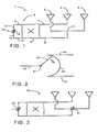
- FIG. 1is a front view of a panel antenna with variable azimuth beam width
- FIG. 2shows a differential phase shifter in detail
- FIG. 3is a front view of a panel antenna with variable azimuth beam width and beam angle
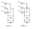
- FIG. 4is a front view of a panel antenna with variable elevation beam width
- FIG. 5is a front view of a panel antenna with variable elevation beam width and beam angle
- FIG. 6is a front view of a panel antenna system with a three column array with adjustable beam width and beam angle in both azimuthal and elevation directions;
- FIG. 7is a variant of FIG. 6 showing a five column array
- FIG. 8is a further variant of FIG. 6 showing a seven column array
- FIG. 9is a plan view of a single cell of a cellular network.
- FIG. 10is a detailed view of a base station.
- an antenna 1 with variable azimuth beam widthcomprising three radiating elements 2 - 4 arranged in a horizontal line and coupled to a power divider/combiner 5 .
- the power divider/combiner 5comprises a 90 degree ring hybrid having antenna ports 7 , 8 and input/output ports 9 , 10 .
- the antenna port 8is coupled to outer elements 2 , 4 via a splitter/combiner 11 , and the antenna port 7 is coupled to the central element 3 .
- the input/output ports 9 , 10are coupled to respective signal lines 12 , 13 of a differential phase shifter 14 .
- the phase shifter 14When working in transmit mode, the phase shifter 14 receives input signals on feed line 15 , splits the signal into two output signals of equal amplitude on lines 12 , 13 , and provides an adjustable differential phase shift between the output signals. Equivalently, in receive mode the phase shifter 14 combines signals on lines 12 , 13 with an adjustable differential relative phase shift.
- the term “differential phase shifter”means an adjustable device which increases the phase of a first signal line, while simultaneously decreases the phase of another signal line by an approximately equal amount.
- the relative power output/input to/from antenna ports 7 , 8varies as a function of the position of the phase shifter 14 . It will be noted that the power coupler 5 is substantially non-attenuating—that is, it does not employ any attenuators (such as resistors) which would result in power loss and overheating.
- the differential phase shifter 14can be any device which simultaneously increases the phase of one line 9 , 10 whilst decreasing the phase of the other line by an approximately equal amount.
- an electromechanical phase shifteris used, which varies phase by adjusting the relative positions of physical components.
- the phase shiftermay comprise a wiper 20 which has a sliding contact with a curved line 22 between signal lines 12 , 13 . Phase is adjusted by rotating wiper 20 about pivot point 21 .
- an arrangement of the type shown in WO 96/14670may be used.
- the phase shiftermay provide continuous adjustment, or may have two or more discrete settings. For instance the phase shifter may have one setting for 33 degree azimuth beam width, and another setting for 45 degree azimuth beam width.
- FIG. 1can also be used to provide azimuth beam steering as shown in FIG. 3 .
- the antenna 30 of FIG. 3is identical to the antenna 1 of FIG. 1 , except that splitter/combiner 11 is replaced by a second differential phase shifter 31 .
- Adjustment of phase shifter 32provides azimuth beam width adjustment, and adjustment of phase shifter 31 provides a progressive phase shift between the three antenna elements, thus providing azimuth beam steering.
- FIGS. 1-3can be extended to providing variable downtilt and elevation beam width as shown in FIGS. 4 and 5 .
- FIGS. 4 and 5are identical to FIGS. 1 and 3 except that the antenna elements 40 - 42 are mounted in a vertical line.
- FIGS. 1-5show linear arrays of antenna elements. However it will be appreciated that the principles exemplified in FIGS. 1-5 can be extended to provide a two-dimensional array with variable beam angle and beam width, each independently adjustable in both azimuth and elevation directions.
- An exampleis given in FIG. 6 .
- First, second and third vertically oriented sub-arrays 53 - 55are each coupled to respective power dividers and phase shifters which provide variable elevation beam angle and variable elevation beam width.
- Variable azimuth beam width and angleis provided by a main hybrid coupler 50 and main phase shifters 51 , 52 .
- a ground plane 56mounted behind the elements 53 - 55 .
- a ground planeis also provided with the antennas of FIGS. 1 , 2 and 4 , 5 but is omitted for clarity.
- azimuth and elevation beam widthcan be adjusted independently in the embodiment of FIG. 6 . That is, elevation beam width can be adjusted whilst keeping the azimuth beam width substantially constant, and vice versa.
- Each parameteris adjusted by its own respective beam width adjuster (ie phase shifter 51 for adjusting azimuth beam width, and three phase shifters 57 - 59 for adjusting elevation beam width).
- the array of FIG. 6could be rotated by 90 degrees: in this case phase shifter 51 would adjust elevation beam width, and phase shifters 57 - 59 would adjust azimuth beam width.
- phase shifters 57 - 59may be driven together in tandem so as to provide uniform elevation beam width adjustment across the width of the array. This may be achieved by means of a mechanical linkage such as a drive rod which drives all three phase shifters 57 - 59 together.
- each line of antenna elements in FIGS. 1-6it will be appreciated that more elements can be added as required.
- the horizontal lines of radiating elementsmay be extended so as to provide a relatively narrow vertically oriented “fan” type of beam pattern, which could for instance be directed onto a tall narrow building.
- the elevation beam widthcan be varied independently of the azimuth beam width—enabling the elevation beam width to be adjusted for the particular height of building.
- Another potential application for independently adjustable elevation beam widthis in a “micro-cellular” mobile wireless communications network.
- a “micro-cellular” networkis a network with a much smaller size and therefore higher capacity than a conventional mobile phone cell, and may be implemented, for example, inside a building. In such a “micro-cellular” network, independent adjustment of elevation beam width may assist network optimisation.
- FIG. 7shows a five column array including a central column 70 , a pair of left-hand columns 71 and a pair of right-hand columns 72 .
- Main power divider 73varies the division of power between the central column 70 and the outer columns 71 , 72 .
- Subsidiary power dividers 74vary the division of power between the inner and outer column of each pair 71 , 72 .
- any arraycan be constructed having 2n+1 rows and 2m+1 columns. Power division between the rows is controlled by a cascaded network of 2n ⁇ 1 power dividers arranged with n cascade levels. Equivalently, power division between the columns is controlled by a cascaded network of 2m ⁇ 1 power dividers arranged with m cascade levels.
- a pair of additional rows and a cascaded power divider networkcan be added to the 3*5 array of FIG. 7 in the same manner, to provide a 5*5 array (not shown).
- an additional pair of columnscan be added as shown in FIG. 8 .
- FIG. 8FIG.
- FIG. 8shows part of the feed network for an array with seven columns and three rows, with three power dividers 81 , 86 , 87 in series controlling the division of power between the columns.
- the radiating elementsare omitted for clarity but their positions are indicated by numerals 82 - 85 .
- Power divider 81varies the division of power between a central column 82 and six outer columns 83 - 85 .
- First subsidiary power dividers 86vary the division of power between the outermost columns 83 and the inner columns 84 , 85 .
- Second subsidiary power dividers 87vary the division of power between columns 84 and 85 .
- a base stationservices a hexagonal cell containing three 120 degree sub-cells 61 - 63 .
- the cellforms part of a cellular or micro-cellular mobile wireless communications network.
- a schematic plan view of the base stationis shown in detail in FIG. 10 .
- the base stationhas three pairs of antennas mounted on a support 107 .
- Antennas 101 , 102have beams 90 , 91 respectively which together service sub-cell 61 .
- Antennas 103 , 104have beams 92 , 93 respectively which together service sub-cell 62 .
- Antennas 105 , 106have beams 94 , 95 respectively which together service sub-cell 63 .
- Each of the antennas 101 - 106has variable downtilt, azimuth beam width and azimuth beam angle as described above.
- the antennas 101 - 106may also incorporate variable elevation beam width.
- the antennas 101 - 106may be panel antennas as shown in FIGS. 6-8 .
- the antennas 101 - 106may be 45 degree dual polarisation antennas, as described for example in WO 02/50953.
- the inventionprovides an antenna in which beam width and/or angle can be varied independently in both azimuth and elevation directions.
- the antennathus allows great flexibility in control of the beam of the antenna to actively control the region covered by an antenna beam in a mobile wireless communications network.
- the inventionis of use generally, but not exclusively, in land-based communications, typically in a mobile wireless communications network.
- the inventionis applicable to a wide range of wireless communications network protocols or frequency bands, including but not limited to cellular, PCS and UMTS.
Landscapes
- Engineering & Computer Science (AREA)
- Computer Networks & Wireless Communication (AREA)
- Variable-Direction Aerials And Aerial Arrays (AREA)
Abstract
Description
Claims (49)
Priority Applications (1)
| Application Number | Priority Date | Filing Date | Title |
|---|---|---|---|
| US10/367,055US6922169B2 (en) | 2003-02-14 | 2003-02-14 | Antenna, base station and power coupler |
Applications Claiming Priority (1)
| Application Number | Priority Date | Filing Date | Title |
|---|---|---|---|
| US10/367,055US6922169B2 (en) | 2003-02-14 | 2003-02-14 | Antenna, base station and power coupler |
Publications (2)
| Publication Number | Publication Date |
|---|---|
| US20040160361A1 US20040160361A1 (en) | 2004-08-19 |
| US6922169B2true US6922169B2 (en) | 2005-07-26 |
Family
ID=32849884
Family Applications (1)
| Application Number | Title | Priority Date | Filing Date |
|---|---|---|---|
| US10/367,055Expired - LifetimeUS6922169B2 (en) | 2003-02-14 | 2003-02-14 | Antenna, base station and power coupler |
Country Status (1)
| Country | Link |
|---|---|
| US (1) | US6922169B2 (en) |
Cited By (20)
| Publication number | Priority date | Publication date | Assignee | Title |
|---|---|---|---|---|
| US20040038714A1 (en)* | 2000-07-10 | 2004-02-26 | Daniel Rhodes | Cellular Antenna |
| US20050017822A1 (en)* | 2002-11-08 | 2005-01-27 | Ems Technologies, Inc. | Variable power divider |
| US20050030249A1 (en)* | 2003-08-06 | 2005-02-10 | Kathrein-Werke Kg | Antenna arrangement and a method in particular for its operation |
| US20050030248A1 (en)* | 2003-08-06 | 2005-02-10 | Kathrein-Werke Kg, | Antenna arrangement |
| US20050037813A1 (en)* | 2003-07-16 | 2005-02-17 | Herbert Germar Jochen | Antenna system for generating and utilizing several small beams from several wide-beam antennas |
| US20060273864A1 (en)* | 2005-06-02 | 2006-12-07 | Zimmerman Martin L | Phase shifter, a phase shifter assembly, feed networks and antennas |
| US20070035361A1 (en)* | 2005-08-12 | 2007-02-15 | Martien Rijssemus | Signal splitter |
| US20070205952A1 (en)* | 2006-03-03 | 2007-09-06 | Gang Yi Deng | Broadband single vertical polarized base station antenna |
| US20080116994A1 (en)* | 2006-11-17 | 2008-05-22 | Hon Hai Precision Industry Co., Ltd. | Circuit topology for multiple loads |
| US20080211600A1 (en)* | 2005-03-22 | 2008-09-04 | Radiaciony Microondas S.A. | Broad Band Mechanical Phase Shifter |
| US20080218425A1 (en)* | 2007-03-05 | 2008-09-11 | Gang Yi Deng | Single pole vertically polarized variable azimuth beamwidth antenna for wireless network |
| US20080246681A1 (en)* | 2007-04-06 | 2008-10-09 | Gang Yi Deng | Dual stagger off settable azimuth beam width controlled antenna for wireless network |
| US20080309568A1 (en)* | 2007-06-13 | 2008-12-18 | Gang Yi Deng | Triple stagger offsetable azimuth beam width controlled antenna for wireless network |
| US20090015498A1 (en)* | 2007-03-08 | 2009-01-15 | Gang Yi Deng | Dual staggered vertically polarized variable azimuth beamwidth antenna for wireless network |
| US20090100491A1 (en)* | 2005-08-12 | 2009-04-16 | Martien Rijssemus | Signal Splitter Circuit |
| US20090146759A1 (en)* | 2007-12-06 | 2009-06-11 | Hon Hai Precision Industry Co., Ltd. | Circuit topology for multiple loads |
| US8912957B2 (en) | 2011-12-12 | 2014-12-16 | Qualcomm Incorporated | Reconfigurable millimeter wave multibeam antenna array |
| US20150023444A1 (en)* | 2009-12-09 | 2015-01-22 | Andrew Wireless Systems Gmbh | Distributed antenna system for mimo signals |
| US10079431B2 (en) | 2008-01-28 | 2018-09-18 | Intel Corporation | Antenna array having mechanically-adjustable radiator elements |
| EP3975339A4 (en)* | 2019-09-12 | 2022-12-21 | Rosenberger Technologies Co., Ltd. | FEED NETWORK TO IMPROVE THE BEAMWIDTH CONVERGENCE OF A BROADBAND ANTENNA |
Families Citing this family (11)
| Publication number | Priority date | Publication date | Assignee | Title |
|---|---|---|---|---|
| KR100482286B1 (en)* | 2002-09-27 | 2005-04-13 | 한국전자통신연구원 | Digital broadcasting service receiver for improving reception ability by switched beamforming |
| US20050219133A1 (en)* | 2004-04-06 | 2005-10-06 | Elliot Robert D | Phase shifting network |
| JP5886401B1 (en)* | 2014-11-13 | 2016-03-16 | 中国電力株式会社 | Combined antenna system |
| CN106159465B (en)* | 2016-09-05 | 2019-08-02 | 广东博纬通信科技有限公司 | Five beam array antenna of wideband |
| WO2018120083A1 (en)* | 2016-12-30 | 2018-07-05 | Panasonic Intellectual Property Corporation Of America | Wireless communication method, apparatus and system |
| EP3419104B1 (en)* | 2017-06-22 | 2022-03-09 | CommScope Technologies LLC | Cellular communication systems having antenna arrays therein with enhanced half power beam width (hpbw) control |
| CN112005503B (en)* | 2018-02-15 | 2022-08-26 | 诺基亚通信公司 | Methods, systems, and apparatus for providing individual antenna configuration selection within a MIMO antenna array |
| CN113315550B (en)* | 2020-02-27 | 2022-03-29 | 上海华为技术有限公司 | Antenna system and access network equipment |
| CN112202413B (en)* | 2020-10-10 | 2023-06-02 | 北京博瑞微电子科技有限公司 | Multi-beam phased array miniaturized asymmetric power synthesis network structure and calibration method |
| CN117353053A (en)* | 2022-06-29 | 2024-01-05 | 华为技术有限公司 | An antenna device and communication equipment |
| CN117117520B (en)* | 2023-10-18 | 2024-01-02 | 中信科移动通信技术股份有限公司 | Antenna |
Citations (21)
| Publication number | Priority date | Publication date | Assignee | Title |
|---|---|---|---|---|
| USRE28546E (en)* | 1972-09-22 | 1975-09-02 | Adjustable polarization antenna system | |
| US4060808A (en)* | 1976-06-30 | 1977-11-29 | Rca Corporation | Antenna system with automatic depolarization correction |
| US4335388A (en) | 1979-02-21 | 1982-06-15 | Ford Aerospace & Communications Corp. | Null control of multiple beam antenna |
| US4626858A (en)* | 1983-04-01 | 1986-12-02 | Kentron International, Inc. | Antenna system |
| US4799065A (en) | 1983-03-17 | 1989-01-17 | Hughes Aircraft Company | Reconfigurable beam antenna |
| US4827270A (en) | 1986-12-22 | 1989-05-02 | Mitsubishi Denki Kabushiki Kaisha | Antenna device |
| USH1034H (en)* | 1990-12-28 | 1992-03-03 | United States Of America | Millimeter wave tracking radar antenna with variable azimuth pattern |
| US5151706A (en) | 1991-01-31 | 1992-09-29 | Agence Spatiale Europeene | Apparatus for electronically controlling the radiation pattern of an antenna having one or more beams of variable width and/or direction |
| US5473294A (en)* | 1993-03-19 | 1995-12-05 | Alenia Spazio S.P.A. | Planar variable power divider |
| WO1996014670A1 (en) | 1994-11-04 | 1996-05-17 | Deltec New Zealand Limited | An antenna control system |
| EP0543509B1 (en) | 1991-11-20 | 1998-07-15 | EMS Technologies, Inc. | Polarization agility in an RF radiator module for use in a phased array |
| US5949370A (en) | 1997-11-07 | 1999-09-07 | Space Systems/Loral, Inc. | Positionable satellite antenna with reconfigurable beam |
| US6208313B1 (en) | 1999-02-25 | 2001-03-27 | Nortel Networks Limited | Sectoral antenna with changeable sector beamwidth capability |
| US6317100B1 (en) | 1999-07-12 | 2001-11-13 | Metawave Communications Corporation | Planar antenna array with parasitic elements providing multiple beams of varying widths |
| WO2002005383A1 (en) | 2000-07-10 | 2002-01-17 | Andrew Corporation | Cellular antenna |
| WO2002015326A2 (en) | 2000-08-15 | 2002-02-21 | Celletra Ltd. | Optimizing clever antenna by beam tilting |
| US20020080068A1 (en) | 2000-12-08 | 2002-06-27 | Kmw Inc. | Base transceiver station having multibeam controllable antenna system |
| WO2002050953A1 (en) | 2000-12-21 | 2002-06-27 | Andrew Corporation | Dual polarisation antenna |
| WO2002061878A2 (en) | 2001-01-29 | 2002-08-08 | Celletra, Ltd. | Antenna arrangements for flexible coverage of a sector in a cellular network |
| US20030153361A1 (en)* | 2002-02-14 | 2003-08-14 | Ntt Docomo, Inc. | Antenna apparatus for base station and method of optimizing traffic capacity in CDMA communications system |
| US20040090286A1 (en) | 2002-11-08 | 2004-05-13 | Ems Technologies, Inc. | Variable power divider |
- 2003
- 2003-02-14USUS10/367,055patent/US6922169B2/ennot_activeExpired - Lifetime
Patent Citations (23)
| Publication number | Priority date | Publication date | Assignee | Title |
|---|---|---|---|---|
| USRE28546E (en)* | 1972-09-22 | 1975-09-02 | Adjustable polarization antenna system | |
| US4060808A (en)* | 1976-06-30 | 1977-11-29 | Rca Corporation | Antenna system with automatic depolarization correction |
| US4335388A (en) | 1979-02-21 | 1982-06-15 | Ford Aerospace & Communications Corp. | Null control of multiple beam antenna |
| US4799065A (en) | 1983-03-17 | 1989-01-17 | Hughes Aircraft Company | Reconfigurable beam antenna |
| US4626858A (en)* | 1983-04-01 | 1986-12-02 | Kentron International, Inc. | Antenna system |
| US4827270A (en) | 1986-12-22 | 1989-05-02 | Mitsubishi Denki Kabushiki Kaisha | Antenna device |
| USH1034H (en)* | 1990-12-28 | 1992-03-03 | United States Of America | Millimeter wave tracking radar antenna with variable azimuth pattern |
| US5151706A (en) | 1991-01-31 | 1992-09-29 | Agence Spatiale Europeene | Apparatus for electronically controlling the radiation pattern of an antenna having one or more beams of variable width and/or direction |
| EP0543509B1 (en) | 1991-11-20 | 1998-07-15 | EMS Technologies, Inc. | Polarization agility in an RF radiator module for use in a phased array |
| US5473294A (en)* | 1993-03-19 | 1995-12-05 | Alenia Spazio S.P.A. | Planar variable power divider |
| WO1996014670A1 (en) | 1994-11-04 | 1996-05-17 | Deltec New Zealand Limited | An antenna control system |
| US6198458B1 (en)* | 1994-11-04 | 2001-03-06 | Deltec Telesystems International Limited | Antenna control system |
| US5949370A (en) | 1997-11-07 | 1999-09-07 | Space Systems/Loral, Inc. | Positionable satellite antenna with reconfigurable beam |
| US6208313B1 (en) | 1999-02-25 | 2001-03-27 | Nortel Networks Limited | Sectoral antenna with changeable sector beamwidth capability |
| US6317100B1 (en) | 1999-07-12 | 2001-11-13 | Metawave Communications Corporation | Planar antenna array with parasitic elements providing multiple beams of varying widths |
| WO2002005383A1 (en) | 2000-07-10 | 2002-01-17 | Andrew Corporation | Cellular antenna |
| WO2002015326A2 (en) | 2000-08-15 | 2002-02-21 | Celletra Ltd. | Optimizing clever antenna by beam tilting |
| US20020080068A1 (en) | 2000-12-08 | 2002-06-27 | Kmw Inc. | Base transceiver station having multibeam controllable antenna system |
| WO2002050953A1 (en) | 2000-12-21 | 2002-06-27 | Andrew Corporation | Dual polarisation antenna |
| WO2002061878A2 (en) | 2001-01-29 | 2002-08-08 | Celletra, Ltd. | Antenna arrangements for flexible coverage of a sector in a cellular network |
| US20040063467A1 (en)* | 2001-01-29 | 2004-04-01 | Joseph Shapira | Antenna arangements for flexible coverage of a sector in a cellular network |
| US20030153361A1 (en)* | 2002-02-14 | 2003-08-14 | Ntt Docomo, Inc. | Antenna apparatus for base station and method of optimizing traffic capacity in CDMA communications system |
| US20040090286A1 (en) | 2002-11-08 | 2004-05-13 | Ems Technologies, Inc. | Variable power divider |
Non-Patent Citations (8)
| Title |
|---|
| Ahmad, "A CDMA Network Architecture Using Optimized Sectoring." IEEE Transactions on Vehicular Technology, vol. 51, No. 3, May 2002. |
| B.M. Schiffman, A New Class of Broad-Band Microwave 90-Degree Phase Shifters, IEEE Transactions on Microwave Theory and Techniques, , vol. 6(2), p. 232-237, Apr. 1958.* |
| D.A. Ellerbruch, Analysis of a Differential Phase Shifter, IEEE Transactions on Microwave Theory and Techniques, vol. 12(4), p. 453-459, Jul. 1964.* |
| F.V. Minnaa et al., A novel ultrawideband microwave differential phase shifter, IEEE Transactions on Microwave Theory and Techniques, vol. 45(8), p. 1249-1252, Aug. 1997.* |
| H. Iwakura et al., 90-degree differential phase shifter using meander-line networks, Electronics-and-Communications-in-Japan Part-1, vol. 68(10), p. 55-62, Oct. 1985.* |
| R.W. Beatty, A Differential Microwave Phase Shifter (Correspondence), IEEE Transactions on Microwave Theory and Techniques, vol. 12(2), p. 250-251, Mar. 1964.* |
| U.S. Appl. No. 60/264,325.* |
| V.P. Meschanov et A new structure of microwave ultrawide-band differential phase shifter, IEEE Transactions on Microwave Theory and Techniques, vol. 42(5), p. 762-765, May 1994.* |
Cited By (44)
| Publication number | Priority date | Publication date | Assignee | Title |
|---|---|---|---|---|
| US7899496B2 (en)* | 2000-07-10 | 2011-03-01 | Andrew Llc | Cellular antenna |
| US20040038714A1 (en)* | 2000-07-10 | 2004-02-26 | Daniel Rhodes | Cellular Antenna |
| US10700754B2 (en) | 2001-11-30 | 2020-06-30 | Andrew Wireless Systems Gmbh | Distributed antenna system for MIMO signals |
| US7474172B2 (en)* | 2002-11-08 | 2009-01-06 | Andrew Corporation | Capacitively coupled variable power divider |
| US20050017822A1 (en)* | 2002-11-08 | 2005-01-27 | Ems Technologies, Inc. | Variable power divider |
| US7221239B2 (en)* | 2002-11-08 | 2007-05-22 | Andrew Corporation | Variable power divider |
| US20070152772A1 (en)* | 2002-11-08 | 2007-07-05 | Runyon Donald L | Capacitively coupled variable power divider |
| US20050037813A1 (en)* | 2003-07-16 | 2005-02-17 | Herbert Germar Jochen | Antenna system for generating and utilizing several small beams from several wide-beam antennas |
| US7280084B2 (en)* | 2003-07-16 | 2007-10-09 | Koninklijke Kpn N.V. | Antenna system for generating and utilizing several small beams from several wide-beam antennas |
| US20050030249A1 (en)* | 2003-08-06 | 2005-02-10 | Kathrein-Werke Kg | Antenna arrangement and a method in particular for its operation |
| US20050030248A1 (en)* | 2003-08-06 | 2005-02-10 | Kathrein-Werke Kg, | Antenna arrangement |
| US7038621B2 (en) | 2003-08-06 | 2006-05-02 | Kathrein-Werke Kg | Antenna arrangement with adjustable radiation pattern and method of operation |
| US7557675B2 (en) | 2005-03-22 | 2009-07-07 | Radiacion Y Microondas, S.A. | Broad band mechanical phase shifter |
| US20080211600A1 (en)* | 2005-03-22 | 2008-09-04 | Radiaciony Microondas S.A. | Broad Band Mechanical Phase Shifter |
| US20060273864A1 (en)* | 2005-06-02 | 2006-12-07 | Zimmerman Martin L | Phase shifter, a phase shifter assembly, feed networks and antennas |
| US7301422B2 (en) | 2005-06-02 | 2007-11-27 | Andrew Corporation | Variable differential phase shifter having a divider wiper arm |
| US7679471B2 (en)* | 2005-08-12 | 2010-03-16 | Technetix Group Limited | Signal splitter circuit with prevention circuitry to reduce generation of intermodulation products |
| TWI399936B (en)* | 2005-08-12 | 2013-06-21 | Technetix Group Ltd | Signal splitter |
| EP2157693A3 (en)* | 2005-08-12 | 2012-02-29 | Technetix Group Limited | Signal splitter |
| US20070035361A1 (en)* | 2005-08-12 | 2007-02-15 | Martien Rijssemus | Signal splitter |
| US20090100491A1 (en)* | 2005-08-12 | 2009-04-16 | Martien Rijssemus | Signal Splitter Circuit |
| US7746194B2 (en)* | 2005-08-12 | 2010-06-29 | Technetix Group Limited | Signal splitter/combiner for reducing noise ingress and cable television network incorporating plurality of same |
| US7864130B2 (en) | 2006-03-03 | 2011-01-04 | Powerwave Technologies, Inc. | Broadband single vertical polarized base station antenna |
| US20070205952A1 (en)* | 2006-03-03 | 2007-09-06 | Gang Yi Deng | Broadband single vertical polarized base station antenna |
| US7843281B2 (en)* | 2006-11-17 | 2010-11-30 | Hon Hai Precision Industry Co., Ltd. | Circuit topology for multiple loads |
| US20080116994A1 (en)* | 2006-11-17 | 2008-05-22 | Hon Hai Precision Industry Co., Ltd. | Circuit topology for multiple loads |
| US20080218425A1 (en)* | 2007-03-05 | 2008-09-11 | Gang Yi Deng | Single pole vertically polarized variable azimuth beamwidth antenna for wireless network |
| US7710344B2 (en) | 2007-03-05 | 2010-05-04 | Powerwave Technologies, Inc. | Single pole vertically polarized variable azimuth beamwidth antenna for wireless network |
| US7990329B2 (en) | 2007-03-08 | 2011-08-02 | Powerwave Technologies Inc. | Dual staggered vertically polarized variable azimuth beamwidth antenna for wireless network |
| US20090015498A1 (en)* | 2007-03-08 | 2009-01-15 | Gang Yi Deng | Dual staggered vertically polarized variable azimuth beamwidth antenna for wireless network |
| US20080246681A1 (en)* | 2007-04-06 | 2008-10-09 | Gang Yi Deng | Dual stagger off settable azimuth beam width controlled antenna for wireless network |
| US8330668B2 (en) | 2007-04-06 | 2012-12-11 | Powerwave Technologies, Inc. | Dual stagger off settable azimuth beam width controlled antenna for wireless network |
| US9806412B2 (en) | 2007-06-13 | 2017-10-31 | Intel Corporation | Triple stagger offsetable azimuth beam width controlled antenna for wireless network |
| US8643559B2 (en) | 2007-06-13 | 2014-02-04 | P-Wave Holdings, Llc | Triple stagger offsetable azimuth beam width controlled antenna for wireless network |
| US20080309568A1 (en)* | 2007-06-13 | 2008-12-18 | Gang Yi Deng | Triple stagger offsetable azimuth beam width controlled antenna for wireless network |
| US20090146759A1 (en)* | 2007-12-06 | 2009-06-11 | Hon Hai Precision Industry Co., Ltd. | Circuit topology for multiple loads |
| US7573353B2 (en)* | 2007-12-06 | 2009-08-11 | Hon Hai Precision Industry Co., Ltd. | Circuit topology for multiple loads |
| US10079431B2 (en) | 2008-01-28 | 2018-09-18 | Intel Corporation | Antenna array having mechanically-adjustable radiator elements |
| US9787385B2 (en) | 2009-12-09 | 2017-10-10 | Andrew Wireless Systems Gmbh | Distributed antenna system for MIMO signals |
| US9246559B2 (en)* | 2009-12-09 | 2016-01-26 | Andrew Wireless Systems Gmbh | Distributed antenna system for MIMO signals |
| US20150023444A1 (en)* | 2009-12-09 | 2015-01-22 | Andrew Wireless Systems Gmbh | Distributed antenna system for mimo signals |
| US8912957B2 (en) | 2011-12-12 | 2014-12-16 | Qualcomm Incorporated | Reconfigurable millimeter wave multibeam antenna array |
| EP3975339A4 (en)* | 2019-09-12 | 2022-12-21 | Rosenberger Technologies Co., Ltd. | FEED NETWORK TO IMPROVE THE BEAMWIDTH CONVERGENCE OF A BROADBAND ANTENNA |
| US12300903B2 (en) | 2019-09-12 | 2025-05-13 | Prose Technologies (Suzhou) Co., Ltd. | Feed network for improving convergence of lobe width of wideband antenna |
Also Published As
| Publication number | Publication date |
|---|---|
| US20040160361A1 (en) | 2004-08-19 |
Similar Documents
| Publication | Publication Date | Title |
|---|---|---|
| US6922169B2 (en) | Antenna, base station and power coupler | |
| CN100508281C (en) | antenna system | |
| US7224246B2 (en) | Apparatus for steering an antenna system | |
| US6963314B2 (en) | Dynamically variable beamwidth and variable azimuth scanning antenna | |
| EP0624919B1 (en) | Multi-beam antenna apparatus | |
| US7450066B2 (en) | Phased array antenna system with adjustable electrical tilt | |
| KR101111467B1 (en) | Phased array antenna system with controllable electrical tilt | |
| TW554570B (en) | Antenna system for use in a wireless communication system | |
| EP0963006B1 (en) | Reconfigurable multiple beam satellite phased array antenna | |
| EP2629362B1 (en) | Shared antenna arrays with multiple independent tilt | |
| US9252485B2 (en) | Phased array antenna system with electrical tilt control | |
| AU2002321653A1 (en) | Antenna system | |
| US6809694B2 (en) | Adjustable beamwidth and azimuth scanning antenna with dipole elements | |
| JP4045793B2 (en) | Multi-beam control antenna system, base station and method | |
| US20040178862A1 (en) | Systems and methods for providing independent transmit paths within a single phased-array antenna | |
| CN116565556B (en) | Ultra-wideband antenna capable of linearly adjusting beam width | |
| HK1074534B (en) | Antenna system | |
| HK1132846A (en) | Antenna system | |
| HK1138111A (en) | Antenna system | |
| AU2002336188A1 (en) | Apparatus for steering an antenna system | |
| HK1099412B (en) | Phased array antenna system with controllable electrical tilt |
Legal Events
| Date | Code | Title | Description |
|---|---|---|---|
| AS | Assignment | Owner name:ANDREW CORP., ILLINOIS Free format text:ASSIGNMENT OF ASSIGNORS INTEREST;ASSIGNORS:IZZAT, NARIAN MOH'D KHEIR MOH'D;ZIMMERMAN, MARTIN LEE;LINEHAN, KEVIN ELDON;REEL/FRAME:014017/0506 Effective date:20030404 | |
| STCF | Information on status: patent grant | Free format text:PATENTED CASE | |
| AS | Assignment | Owner name:BANK OF AMERICA, N.A., AS ADMINISTRATIVE AGENT, CA Free format text:SECURITY AGREEMENT;ASSIGNORS:COMMSCOPE, INC. OF NORTH CAROLINA;ALLEN TELECOM, LLC;ANDREW CORPORATION;REEL/FRAME:020362/0241 Effective date:20071227 Owner name:BANK OF AMERICA, N.A., AS ADMINISTRATIVE AGENT,CAL Free format text:SECURITY AGREEMENT;ASSIGNORS:COMMSCOPE, INC. OF NORTH CAROLINA;ALLEN TELECOM, LLC;ANDREW CORPORATION;REEL/FRAME:020362/0241 Effective date:20071227 | |
| AS | Assignment | Owner name:ANDREW LLC, NORTH CAROLINA Free format text:CHANGE OF NAME;ASSIGNOR:ANDREW CORPORATION;REEL/FRAME:021805/0276 Effective date:20080827 | |
| FPAY | Fee payment | Year of fee payment:4 | |
| AS | Assignment | Owner name:COMMSCOPE, INC. OF NORTH CAROLINA, NORTH CAROLINA Free format text:PATENT RELEASE;ASSIGNOR:BANK OF AMERICA, N.A., AS ADMINISTRATIVE AGENT;REEL/FRAME:026039/0005 Effective date:20110114 Owner name:ANDREW LLC (F/K/A ANDREW CORPORATION), NORTH CAROL Free format text:PATENT RELEASE;ASSIGNOR:BANK OF AMERICA, N.A., AS ADMINISTRATIVE AGENT;REEL/FRAME:026039/0005 Effective date:20110114 Owner name:ALLEN TELECOM LLC, NORTH CAROLINA Free format text:PATENT RELEASE;ASSIGNOR:BANK OF AMERICA, N.A., AS ADMINISTRATIVE AGENT;REEL/FRAME:026039/0005 Effective date:20110114 | |
| AS | Assignment | Owner name:JPMORGAN CHASE BANK, N.A., AS COLLATERAL AGENT, NE Free format text:SECURITY AGREEMENT;ASSIGNORS:ALLEN TELECOM LLC, A DELAWARE LLC;ANDREW LLC, A DELAWARE LLC;COMMSCOPE, INC. OF NORTH CAROLINA, A NORTH CAROLINA CORPORATION;REEL/FRAME:026276/0363 Effective date:20110114 | |
| AS | Assignment | Owner name:JPMORGAN CHASE BANK, N.A., AS COLLATERAL AGENT, NE Free format text:SECURITY AGREEMENT;ASSIGNORS:ALLEN TELECOM LLC, A DELAWARE LLC;ANDREW LLC, A DELAWARE LLC;COMMSCOPE, INC OF NORTH CAROLINA, A NORTH CAROLINA CORPORATION;REEL/FRAME:026272/0543 Effective date:20110114 | |
| FPAY | Fee payment | Year of fee payment:8 | |
| AS | Assignment | Owner name:COMMSCOPE TECHNOLOGIES LLC, NORTH CAROLINA Free format text:CHANGE OF NAME;ASSIGNOR:ANDREW LLC;REEL/FRAME:035283/0849 Effective date:20150301 | |
| AS | Assignment | Owner name:WILMINGTON TRUST, NATIONAL ASSOCIATION, AS COLLATERAL AGENT, CONNECTICUT Free format text:SECURITY INTEREST;ASSIGNORS:ALLEN TELECOM LLC;COMMSCOPE TECHNOLOGIES LLC;COMMSCOPE, INC. OF NORTH CAROLINA;AND OTHERS;REEL/FRAME:036201/0283 Effective date:20150611 Owner name:WILMINGTON TRUST, NATIONAL ASSOCIATION, AS COLLATE Free format text:SECURITY INTEREST;ASSIGNORS:ALLEN TELECOM LLC;COMMSCOPE TECHNOLOGIES LLC;COMMSCOPE, INC. OF NORTH CAROLINA;AND OTHERS;REEL/FRAME:036201/0283 Effective date:20150611 | |
| FPAY | Fee payment | Year of fee payment:12 | |
| AS | Assignment | Owner name:ALLEN TELECOM LLC, NORTH CAROLINA Free format text:RELEASE OF SECURITY INTEREST PATENTS (RELEASES RF 036201/0283);ASSIGNOR:WILMINGTON TRUST, NATIONAL ASSOCIATION;REEL/FRAME:042126/0434 Effective date:20170317 Owner name:REDWOOD SYSTEMS, INC., NORTH CAROLINA Free format text:RELEASE OF SECURITY INTEREST PATENTS (RELEASES RF 036201/0283);ASSIGNOR:WILMINGTON TRUST, NATIONAL ASSOCIATION;REEL/FRAME:042126/0434 Effective date:20170317 Owner name:COMMSCOPE TECHNOLOGIES LLC, NORTH CAROLINA Free format text:RELEASE OF SECURITY INTEREST PATENTS (RELEASES RF 036201/0283);ASSIGNOR:WILMINGTON TRUST, NATIONAL ASSOCIATION;REEL/FRAME:042126/0434 Effective date:20170317 Owner name:COMMSCOPE, INC. OF NORTH CAROLINA, NORTH CAROLINA Free format text:RELEASE OF SECURITY INTEREST PATENTS (RELEASES RF 036201/0283);ASSIGNOR:WILMINGTON TRUST, NATIONAL ASSOCIATION;REEL/FRAME:042126/0434 Effective date:20170317 | |
| AS | Assignment | Owner name:ANDREW LLC, NORTH CAROLINA Free format text:CORRECTIVE ASSIGNMENT TO CORRECT THE DELETE THE WRONG PROPERTY NJMBER PREVIOUSLY RECORDED AT REEL: 021805 FRAME: 0276. ASSIGNOR(S) HEREBY CONFIRMS THE ASSIGNMENT;ASSIGNOR:ANDREW CORPORATION;REEL/FRAME:046377/0458 Effective date:20080827 | |
| AS | Assignment | Owner name:ALLEN TELECOM LLC, ILLINOIS Free format text:RELEASE BY SECURED PARTY;ASSIGNOR:JPMORGAN CHASE BANK, N.A.;REEL/FRAME:048840/0001 Effective date:20190404 Owner name:COMMSCOPE TECHNOLOGIES LLC, NORTH CAROLINA Free format text:RELEASE BY SECURED PARTY;ASSIGNOR:JPMORGAN CHASE BANK, N.A.;REEL/FRAME:048840/0001 Effective date:20190404 Owner name:REDWOOD SYSTEMS, INC., NORTH CAROLINA Free format text:RELEASE BY SECURED PARTY;ASSIGNOR:JPMORGAN CHASE BANK, N.A.;REEL/FRAME:048840/0001 Effective date:20190404 Owner name:COMMSCOPE, INC. OF NORTH CAROLINA, NORTH CAROLINA Free format text:RELEASE BY SECURED PARTY;ASSIGNOR:JPMORGAN CHASE BANK, N.A.;REEL/FRAME:048840/0001 Effective date:20190404 Owner name:ANDREW LLC, NORTH CAROLINA Free format text:RELEASE BY SECURED PARTY;ASSIGNOR:JPMORGAN CHASE BANK, N.A.;REEL/FRAME:048840/0001 Effective date:20190404 Owner name:COMMSCOPE, INC. OF NORTH CAROLINA, NORTH CAROLINA Free format text:RELEASE BY SECURED PARTY;ASSIGNOR:JPMORGAN CHASE BANK, N.A.;REEL/FRAME:049260/0001 Effective date:20190404 Owner name:ALLEN TELECOM LLC, ILLINOIS Free format text:RELEASE BY SECURED PARTY;ASSIGNOR:JPMORGAN CHASE BANK, N.A.;REEL/FRAME:049260/0001 Effective date:20190404 Owner name:ANDREW LLC, NORTH CAROLINA Free format text:RELEASE BY SECURED PARTY;ASSIGNOR:JPMORGAN CHASE BANK, N.A.;REEL/FRAME:049260/0001 Effective date:20190404 Owner name:COMMSCOPE TECHNOLOGIES LLC, NORTH CAROLINA Free format text:RELEASE BY SECURED PARTY;ASSIGNOR:JPMORGAN CHASE BANK, N.A.;REEL/FRAME:049260/0001 Effective date:20190404 Owner name:REDWOOD SYSTEMS, INC., NORTH CAROLINA Free format text:RELEASE BY SECURED PARTY;ASSIGNOR:JPMORGAN CHASE BANK, N.A.;REEL/FRAME:049260/0001 Effective date:20190404 | |
| AS | Assignment | Owner name:JPMORGAN CHASE BANK, N.A., NEW YORK Free format text:TERM LOAN SECURITY AGREEMENT;ASSIGNORS:COMMSCOPE, INC. OF NORTH CAROLINA;COMMSCOPE TECHNOLOGIES LLC;ARRIS ENTERPRISES LLC;AND OTHERS;REEL/FRAME:049905/0504 Effective date:20190404 Owner name:JPMORGAN CHASE BANK, N.A., NEW YORK Free format text:ABL SECURITY AGREEMENT;ASSIGNORS:COMMSCOPE, INC. OF NORTH CAROLINA;COMMSCOPE TECHNOLOGIES LLC;ARRIS ENTERPRISES LLC;AND OTHERS;REEL/FRAME:049892/0396 Effective date:20190404 Owner name:WILMINGTON TRUST, NATIONAL ASSOCIATION, AS COLLATE Free format text:PATENT SECURITY AGREEMENT;ASSIGNOR:COMMSCOPE TECHNOLOGIES LLC;REEL/FRAME:049892/0051 Effective date:20190404 Owner name:WILMINGTON TRUST, NATIONAL ASSOCIATION, AS COLLATERAL AGENT, CONNECTICUT Free format text:PATENT SECURITY AGREEMENT;ASSIGNOR:COMMSCOPE TECHNOLOGIES LLC;REEL/FRAME:049892/0051 Effective date:20190404 | |
| AS | Assignment | Owner name:WILMINGTON TRUST, DELAWARE Free format text:SECURITY INTEREST;ASSIGNORS:ARRIS SOLUTIONS, INC.;ARRIS ENTERPRISES LLC;COMMSCOPE TECHNOLOGIES LLC;AND OTHERS;REEL/FRAME:060752/0001 Effective date:20211115 | |
| AS | Assignment | Owner name:RUCKUS WIRELESS, LLC (F/K/A RUCKUS WIRELESS, INC.), NORTH CAROLINA Free format text:RELEASE OF SECURITY INTEREST AT REEL/FRAME 049905/0504;ASSIGNOR:JPMORGAN CHASE BANK, N.A., AS COLLATERAL AGENT;REEL/FRAME:071477/0255 Effective date:20241217 Owner name:COMMSCOPE TECHNOLOGIES LLC, NORTH CAROLINA Free format text:RELEASE OF SECURITY INTEREST AT REEL/FRAME 049905/0504;ASSIGNOR:JPMORGAN CHASE BANK, N.A., AS COLLATERAL AGENT;REEL/FRAME:071477/0255 Effective date:20241217 Owner name:COMMSCOPE, INC. OF NORTH CAROLINA, NORTH CAROLINA Free format text:RELEASE OF SECURITY INTEREST AT REEL/FRAME 049905/0504;ASSIGNOR:JPMORGAN CHASE BANK, N.A., AS COLLATERAL AGENT;REEL/FRAME:071477/0255 Effective date:20241217 Owner name:ARRIS SOLUTIONS, INC., NORTH CAROLINA Free format text:RELEASE OF SECURITY INTEREST AT REEL/FRAME 049905/0504;ASSIGNOR:JPMORGAN CHASE BANK, N.A., AS COLLATERAL AGENT;REEL/FRAME:071477/0255 Effective date:20241217 Owner name:ARRIS TECHNOLOGY, INC., NORTH CAROLINA Free format text:RELEASE OF SECURITY INTEREST AT REEL/FRAME 049905/0504;ASSIGNOR:JPMORGAN CHASE BANK, N.A., AS COLLATERAL AGENT;REEL/FRAME:071477/0255 Effective date:20241217 Owner name:ARRIS ENTERPRISES LLC (F/K/A ARRIS ENTERPRISES, INC.), NORTH CAROLINA Free format text:RELEASE OF SECURITY INTEREST AT REEL/FRAME 049905/0504;ASSIGNOR:JPMORGAN CHASE BANK, N.A., AS COLLATERAL AGENT;REEL/FRAME:071477/0255 Effective date:20241217 |