US6920925B2 - Wellhead isolation tool - Google Patents
Wellhead isolation toolDownload PDFInfo
- Publication number
- US6920925B2 US6920925B2US10/369,070US36907003AUS6920925B2US 6920925 B2US6920925 B2US 6920925B2US 36907003 AUS36907003 AUS 36907003AUS 6920925 B2US6920925 B2US 6920925B2
- Authority
- US
- United States
- Prior art keywords
- flange
- tubular member
- section
- annular member
- elongate annular
- Prior art date
- Legal status (The legal status is an assumption and is not a legal conclusion. Google has not performed a legal analysis and makes no representation as to the accuracy of the status listed.)
- Expired - Lifetime
Links
- 238000002955isolationMethods0.000titleabstractdescription134
- 238000004519manufacturing processMethods0.000claimsabstractdescription40
- 230000000295complement effectEffects0.000claimsdescription7
- 230000008878couplingEffects0.000claims3
- 238000010168coupling processMethods0.000claims3
- 238000005859coupling reactionMethods0.000claims3
- 238000000034methodMethods0.000description18
- 230000008569processEffects0.000description12
- 238000007789sealingMethods0.000description12
- 238000002360preparation methodMethods0.000description9
- 238000012360testing methodMethods0.000description9
- 230000015572biosynthetic processEffects0.000description4
- 238000005755formation reactionMethods0.000description4
- 230000013011matingEffects0.000description4
- 230000000149penetrating effectEffects0.000description4
- 239000003082abrasive agentSubstances0.000description3
- 230000008901benefitEffects0.000description3
- 230000014759maintenance of locationEffects0.000description3
- 239000000463materialSubstances0.000description3
- 230000000712assemblyEffects0.000description2
- 238000000429assemblyMethods0.000description2
- 238000004891communicationMethods0.000description2
- 230000000694effectsEffects0.000description2
- 210000002445nippleAnatomy0.000description2
- 230000000717retained effectEffects0.000description2
- 239000000725suspensionSubstances0.000description2
- 229910000851Alloy steelInorganic materials0.000description1
- 229910000831SteelInorganic materials0.000description1
- 230000004308accommodationEffects0.000description1
- 230000003466anti-cipated effectEffects0.000description1
- 238000009844basic oxygen steelmakingMethods0.000description1
- 229910001570bauxiteInorganic materials0.000description1
- 238000005266castingMethods0.000description1
- 230000002708enhancing effectEffects0.000description1
- 239000012530fluidSubstances0.000description1
- 238000005242forgingMethods0.000description1
- 229930195733hydrocarbonNatural products0.000description1
- 150000002430hydrocarbonsChemical class0.000description1
- 238000009434installationMethods0.000description1
- 238000003754machiningMethods0.000description1
- 238000012986modificationMethods0.000description1
- 230000004048modificationEffects0.000description1
- 238000012544monitoring processMethods0.000description1
- 230000000246remedial effectEffects0.000description1
- 239000004576sandSubstances0.000description1
- 125000006850spacer groupChemical group0.000description1
- 239000010935stainless steelSubstances0.000description1
- 229910001220stainless steelInorganic materials0.000description1
- 239000010959steelSubstances0.000description1
- 230000000638stimulationEffects0.000description1
Images


Classifications
- E—FIXED CONSTRUCTIONS
- E21—EARTH OR ROCK DRILLING; MINING
- E21B—EARTH OR ROCK DRILLING; OBTAINING OIL, GAS, WATER, SOLUBLE OR MELTABLE MATERIALS OR A SLURRY OF MINERALS FROM WELLS
- E21B33/00—Sealing or packing boreholes or wells
- E21B33/02—Surface sealing or packing
- E21B33/03—Well heads; Setting-up thereof
- E21B33/068—Well heads; Setting-up thereof having provision for introducing objects or fluids into, or removing objects from, wells
Definitions
- the present inventionrelates to wellhead equipment, and to a wellhead tool for isolating wellhead equipment from the extreme pressures and abrasive materials used in oil and gas well stimulation.
- Oil and gas wellsoften require remedial actions in order to enhance production of hydrocarbons from the producing zones of subterranean formations. These actions include a process called fracturing whereby fluids are pumped into the formation at high pressures in order to break up the product bearing zone. This is done to increase the flow of the product to the well bore where it is collected and retrieved. Abrasive materials, such as sand or bauxite, called propates are also pumped into the fractures created in the formation to prop the fractures open allowing an increase in product flow. These procedures are a normal part of placing a new well into production and are common in older wells as the formation near the well bore begins to dry up. These procedures may also be required in older wells that tend to collapse in the subterranean zone as product is depleted in order to maintain open flow paths to the well bore.
- the surface wellhead equipmentis usually rated to handle the anticipated pressures that might be produced by the well when it first enters production.
- the pressures encountered during the fracturing processare normally considerably higher than those of the producing well.
- a meansmust be provided whereby the elevated pressures are safely contained and means must also be provided to control the well pressures. It is common in the industry to accomplish these requirements by using a ‘stinger’ that is rated for the pressures to be encountered. The ‘stinger’ reaches through the wellhead and into the tubing or casing through which the fracturing process is to be communicated to the producing subterranean zone.
- the ‘stinger’also commonly extends through a blow out preventer (BOP) that has been placed on the top of the wellhead to control well pressures. Therefore, the ‘stinger’, by its nature, has a reduced bore which typically restricts the flow into the well during the fracturing process. Additionally, the placement of the BOP on the wellhead requires substantial ancillary equipment due to its size and weight.
- BOPblow out preventer
- the present inventionis directed to a wellhead isolation tool and to a wellhead assembly incorporating the same.
- the present inventionin an exemplary embodiment provides for a wellhead isolation tool, also referred to as a “frac mandrel” that cooperates with a relatively low pressure wellhead to accommodate the elevated pressures encountered during the fracturing process by taking advantage of the heavier material cross-section present in the lower end of wellhead equipment and by isolating the weaker upper portions of the wellhead from high fracturing pressures.
- Said toolprovides a full diameter access into the well bore, thus enhancing the fracturing process, and may be used with common high pressure valves to provide well pressure control.
- the inventionfurther provides for retention of standard profiles within the upper portion of the wellhead allowing the use of standard tubing hangers to support production tubing within the completed well.
- a wellhead deviceis provided that is operable with a conventional high pressure valve for controlling well pressure having at least one string of tubulars.
- the wellhead deviceconsists of a wellhead body member and a cooperating wellhead isolation tool.
- a wellhead body memberis provided with an internal through bore communicating with the upper end of a string of tubulars.
- the lower end of the wellhead body membermay be provided with a means to threadedly engage the tubulars, be welded to the tubulars, or slipped over the tubulars and otherwise sealed.
- the upper end of wellhead body membermay be provided with a flanged connection or otherwise furnished with an alternative means of connecting completion equipment, and is further provided with an internal through bore preparation, known in the art as a bowl, to allow suspension of production tubulars.
- An intermediate connection or connections, either threaded or studded flangeis provided within the wall of the wellhead body member affecting a transverse access port to the annular area between the wellhead body member and the production tubulars.
- a through bore preparation of the wellhead body memberis provided between the transverse access port and lower end tubular accommodation that cooperates with lower end and seals of the wellhead isolation tool.
- the upper flanged end of the wellhead body memberis provided with a plurality of radial threaded ports. Said radial ports are provided with cooperating threaded devices, commonly referred to as lock screws, for the purpose of retaining equipment within the upper bowl of the wellhead body member. The quantity of these lock screws is determined by the pressure rating of the wellhead body member in combination with other parameters.
- the exemplary embodiment wellhead isolation toolis provided with a through bore that equals the through bore of the wellhead tubulars, thus maximizing flow characteristics through the tool.
- the upper end of the wellhead isolation toolis provided with a flange rated to accommodate fracturing pressures and suitable for the installation of equipment pertinent to the fracturing process.
- the outer surface of the lower end of wellhead isolation toolcooperates with the lower bore preparation of the wellhead body member and is equipped with a pair of seals that provide isolation of the through bore of the wellhead isolation tool from the upper bore area of the wellhead body member.
- a radial threaded portis provided in the wall of the wellhead body member in such a location as to provide a means to test the effectiveness of the isolation seals of the wellhead isolation tool after it is installed in the wellhead body member.
- the mediate portion of the wellhead isolation toolis provided with an external profile that cooperates with the upper bowl profile of the wellhead body member to establish the proper vertical positioning of the wellhead isolation tool.
- the outside periphery of this embodiment of the wellhead isolation toolis provided with a pair of grooves formed in the shape of a truncated “V”. The resulting lower conic surface of the lowermost “V” groove cooperates with frustroconical ends of the lock screws when the lock screws are threaded into place through their cooperating ports in the flange of the upper end of the wellhead body member to affect retention of the wellhead isolation tool within the wellhead body member.
- an additional flangeknown in the art as a secondary tie down flange, is provided that cooperates with the upper flange of the wellhead body member by a plurality of bolts or studs installed through matching holes machined in the flanges.
- This additional flangeis also provided with a plurality of radial threaded ports in which cooperating lock screws are installed to provide additional retention capacity of the wellhead isolation tool.
- the frustroconical ends of the latter lock screwscooperate with the lower conic surface of the uppermost “V” groove provided in the wellhead isolation tool to provide the additional strength required to adequately retain the wellhead isolation tool within the wellhead body member.
- the additional flangecould be furnished as an integral part of the wellhead isolation tool.
- the mediate portion of the toolis provided with an external profile that acts independently from the upper bowl profile of the wellhead body member and with a mounting flange that is threadedly connected to the wellhead solation tool.
- the lower end configuration of the second version of the wellhead isolation toolis the same as in the first exemplary embodiment and seals within the cooperating bore of the wellhead body member.
- the mounting flangemay be provided as an integral part of the wellhead isolation tool.
- the wellhead isolation toolpenetrates a tubing head and a mandrel casing hanger which is seated within a casing head. A portion of the tubing head also penetrates the mandrel casing hanger. A latch and a top nut are used to retain mandrel casing hanger in the tubing head. The wellhead isolation tool seals at its lower end against the mandrel casing hanger.
- the wellhead isolation toolpenetrates a combination tubing head/casing head and seals against a casing hanger which is seated within the tubing head/casing head combination.
- the casing hangeris retained within the tubing head/casing head combination by a latch and a top nut.
- the wellhead isolation toolseals at its lower end against the casing hanger.
- the top nut used with any of the aforementioned embodimentscan have an expanded upper portion for the landing of additional wellhead equipment.
- FIG. 1is a partial cross-sectional view of a typical wellhead with an exemplary embodiment wellhead isolation tool of the present invention and a fracturing tree assembly.
- FIG. 2is a partial cross-sectional view of a typical wellhead with another exemplary embodiment wellhead isolation tool of the present invention and a fracturing tree assembly.
- FIG. 3is an enlarged cross-sectional view encircled by arrow 3 — 3 in FIG. 1 .
- FIG. 4Ais an enlarged cross-sectional view encircled by arrow 4 A— 4 A in FIG. 1 .
- FIG. 4Bis the same view as FIG. 4A with the cooperating lock screws shown in a retracted position.
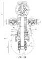
- FIG. 5is an enlarged cross-sectional view of the section encircled by arrow 5 — 5 in FIG. 2 .
- FIG. 6is an enlarged cross-sectional view of the section encircled by arrow 6 — 6 in FIG. 2 .
- FIG. 7Ais a partial cross-sectional view of an exemplary embodiment wellhead incorporating an exemplary embodiment wellhead isolation tool of the present invention.
- FIG. 7Bis an enlarged cross-sectional view of the area encircled by arrow 7 B— 7 B in FIG. 7A ;
- FIG. 8is a partial cross-sectional view of another exemplary embodiment wellhead incorporating another exemplary embodiment wellhead isolation tool of the present invention.
- the exemplary embodiment wellhead assembly 1includes a lower housing assembly 10 also referred to herein as a casing head assembly; an upper assembly 80 also referred to herein as a fracturing tree; an intermediate body member assembly 20 also referred to herein as a tubing head assembly; and a wellhead isolation tool or member 60 , which is an elongate annular member, also referred to herein as a frac mandrel. It will be recognized by those skilled in the art that there may be differing configurations of wellhead assembly 1 .
- the casing head assemblyincludes a casing head 13 defining a well bore 15 .
- the lower end 26 of casing head 13is connected and sealed to surface casing 12 either by a welded connection as shown or by other means such as a threaded connection (not shown).
- the tubing head assembly 20includes a body member referred to herein as the “tubing head” 22 .
- the upper end 14 of casing head 13cooperates with a lower end 24 of body member 22 whether by a flanged connection as shown or by other means.
- a production casing 18is suspended within the well bore 15 by hanger 16 .
- the upper end of production casing 18extends into the body member and cooperates with the lower bore preparation 28 of body member 22 .
- the juncture of production casing 18 and lower bore preparation 28is sealed by seals 32 .
- the seals 32which may be standard or specially molded seals.
- the sealsare self energizing seals such as for example O-ring, T-seal or S-seal types of seals. Self-energizing seals do not need excessive mechanical forces for forming a seal.
- Grooves 33may be formed on the inner surface 35 of the body member 22 to accommodate the seals 32 , as shown in FIG. 3 , so that the seals seal against an outer surface 37 of the production casing 18 and the grooves 33 .
- the seals 32prevent the communication of pressure contained within the production casing inner bore 34 to the cavity 38 defined in the upper portion of the well bore 15 of the casing head 13 .
- groovesmay be formed on the outer surface 37 of the production casing 18 to accommodate the seals 32 . With this embodiment, the seals seal against the inner surface 35 of the body member.
- other seals or methods of sealingmay be used to prevent the communication of pressure contained within the production casing inner bore 34 to cavity 38 defined in the upper portion of the well bore 15 of the casing head 13 .
- the production casing 18may also be threadedly suspended within the casing head 13 by what is known in the art as an extended neck mandrel hanger (not shown) whereby the extended neck of said mandrel hanger cooperates with the lower cylindrical bore preparation 28 of body member 22 in same manner as the upper end of production casing 18 and whose juncture with lower cylindrical bore preparation 28 of body member 22 is sealed in the same manner as previously described.
- the body member 22includes an upper flange 42 .
- a secondary flange 70is installed on the upper flange 42 of body member utilizing a plurality of studs 44 and nuts 45 .
- a spacer 50cooperates with a groove 46 in secondary flange 70 and a groove 48 in the upper flange 42 of body member 22 in order to maintain concentricity between secondary flange 70 and upper flange 42 .
- lock screws 40having frustum-conical ends 66 threadedly cooperate with retainer nuts 68 which, in turn, threadedly cooperate with radial threaded ports 72 in upper flange 42 of body member 22 and radial threaded ports 74 in secondary flange 70 .
- the lock screws 40may be threadedly retracted to allow unrestricted access through bore 92 defined through the secondary flange 70 as for example shown in FIG. 4 B.
- an exemplary embodiment wellhead isolation tool 60is installed through cylindrical bore 92 in secondary flange 70 and into the body member 22 .
- the exemplary embodiment wellhead isolation tool shown in FIG. 1is a generally elongated annular member having an inner surface 200 having a first section 202 having a first diameter and a second section 204 extending below the first section and having diameter smaller than that of the first section (FIG. 4 A). Consequently, a shoulder 206 is defined between the two sections as for example shown in FIG. 4 A.
- a radial flange 208extends from an upper end of the wellhead isolation tool and provides an interface for connecting the upper assembly or fracturing tree 80 as shown in FIG. 1.
- a first annular groove 212is formed over a second annular groove 214 on an outer surface 210 of the wellhead isolation tool, as for example shown in FIGS. 4A and 4B .
- the groovesare frustum-conical, i.e, they have an upper tapering surface 215 and a lower tapering surface 64 as shown in FIG. 4 B.
- a first set of depressions(not shown) is formed over as second set of depressions (not shown) on the outer surface of the wellhead isolation tool. Each set of depressions is radially arranged around the outer surface of the wellhead isolation tool. These depressions also have a frustum-conical cross-sectional shape.
- the outer surface 210 of the well head isolation toolhas an upper tapering portion 54 tapering from a larger diameter upper portion 218 to a smaller diameter lower portion 222 .
- a lower tapering portion 220extends below the upper tapering portion 54 , tapering the outer surface of the wellhead isolation tool to a smaller diameter lower portion 222 .
- the upper outer surface tapering portion 54 of the wellhead isolation toolmates with a complementary tapering inner surface portion 52 of the body member 22 as shown in FIG. 4B.
- a sealis provided between the wellhead isolation tool and the body member 22 .
- the sealmay be provided using seals 56 , as for example self energizing seals such as for example O-ring, T-seal and S-seal type seals fitted in grooves 58 formed on the upper tapering portion 54 of the outer surface of the wellhead isolation tool.
- the sealsare fitted in grooves on the tapering inner surface portion of the body member.
- the lock screws 40 penetrating the secondary flange 70are aligned with the upper groove 212 formed on the wellhead isolation tool outer surface and the lock screws 40 penetrating the upper flange 42 of the body member 22 are aligned with lower groove 214 formed on the outer surface of the wellhead isolation tool.
- the mandrelmay have to be rotated such that the lock screws 40 penetrating the secondary flange are aligned with a first set of depressions (not shown) formed on the wellhead isolation tool outer surface and the lock screws 40 penetrating the upper flange of the body member 22 are aligned with a second set depressions (not shown) formed on the outer surface of the wellhead isolation tool.
- lock screws 40are threadedly inserted so that their frustum conical ends 66 engage the lower tapering surfaces 64 of their respective grooves 212 , 214 formed on the outer surface of the exemplary wellhead isolation too). 60 thereby, retaining the wellhead isolation tool 60 within body member 22 .
- excess loads on the wellhead isolation tool 60 not absorbed by lock screws 40 installed in upper flange 42are absorbed by lock screws 40 installed in secondary flange 70 and redistributed through studs 44 and nuts 45 to upper flange 42 .
- the outer cylindrical surface 78 of the wellhead isolation tool lower portion 222cooperates with inner surface 76 of the body member 22 .
- Seals 82are installed in grooves 84 formed in outer surface 78 of the wellhead isolation tool and cooperate with surfaces 76 to effect a seal between the body member 22 and the wellhead isolation tool 60 .
- the sealsare self energizing seals such as for example O-ring, T-seal or S-seal types of seals.
- the sealsmay be fitted in the grooves formed on in the inner surface 76 of the body member.
- Pipe port 88is radially formed through body member 22 and provides access for testing seals 82 prior to placing the wellhead isolation tool 60 in service. Subsequent to testing, pipe port 88 is sealed in an exemplary embodiment with pipe plug 90 . Testing may be accomplished by applying air pressure through the pipe port 88 and monitoring the pressure for a decrease. A decrease in pressure of a predetermined amount over a predetermined time period may be indicative of seal leakage.
- Cylindrical bores 34 , 36 and 86 defined through the production casing 18 , the exemplary embodiment wellhead isolation tool 60 , and through an annular lip portion 87 the body member 22 , respectively,are in an exemplary embodiment as shown in FIG. 3 equal in diameter thus providing an unrestricted passageway for fracturing materials and/or downhole tools.
- valve 96is connected to body member 22 by pipe nipple 94 .
- Valve 96may also be connected to the body member 22 by a flanged or studded outlet preparation. Valve 96 may then be opened during the fracturing process to bleed high pressures from cavity 98 in the event of leakage past seals 82 .
- FIG. 2shows another exemplary embodiment wellhead assembly 2 consisting of a lower housing assembly 10 also referred to herein as a casing head assembly; an upper assembly 80 also referred to herein as a fracturing tree; an intermediate body member assembly 20 also referred to herein as a body member assembly; and another exemplary embodiment wellhead isolation tool 100 also referred to herein as a wellhead isolation tool.
- a lower housing assembly 10also referred to herein as a casing head assembly
- an upper assembly 80also referred to herein as a fracturing tree
- an intermediate body member assembly 20also referred to herein as a body member assembly
- another exemplary embodiment wellhead isolation tool 100also referred to herein as a wellhead isolation tool.
- a secondary flange 110is provided in an exemplary embodiment with threads 118 , preferably ACME threads, on its inner cylindrical surface that cooperate with threads 116 , also in an exemplary embodiment preferably ACME, on the outer cylindrical surface of wellhead isolation tool 100 .
- secondary flange 110may be incorporated as an integral part of wellhead isolation tool 100 .
- the assembled toolmay be produced more economically with a threaded on secondary flange 110 as for example shown in FIG. 6 .
- the assembly of secondary flange 110 and wellhead isolation tool 100is coupled to on the upper flange 42 of body member 22 utilizing a plurality of studs 44 and nuts 45 .
- a standard sealing gasket 51cooperates with a groove 108 formed in the wellhead isolation tool 100 and groove 48 in the upper flange 42 of body member 22 in order to maintain concentricity and a seal between wellhead isolation tool 100 and upper flange 42 .
- excess loads on the wellhead isolation tool 100are transmitted to the flange 110 and redistributed through studs 44 and nuts 45 to upper flange 42 .
- outer surface 106 of wellhead isolation tool 100cooperates with cylindrical bore surface 76 of body member 22 .
- Seals 112 installed in grooves 104 machined in outer surface 106 of wellhead isolation tool 100cooperate with surfaces 76 to effect a seal between body member 22 and wellhead isolation tool 100 .
- the sealsare fitted in grooves formed on the inner bore surface 76 of body member 22 and cooperate with the outer surface 106 of the wellhead isolation tool.
- the sealsare self energizing seals as for example O-ring, T-seal and S-seal type seals. Other sealing schemes known in the art may also be used in lieu or in combination with the sealing schemes described herein.
- pipe port 88 radially formed through body member 22provides access for testing seals 112 prior to placing wellhead isolation tool 100 in service. Subsequent to testing, pipe port 88 is sealed with pipe plug 90 .
- Cylindrical bores 34 , 102 and 86 formed through the production casing 18 , through the exemplary embodiment wellhead isolation tool 100 , and through the annular lip portion on 87 of the body member 22 , respectively,are in an exemplary embodiment equal in diameter thus providing an unrestricted passageway for fracturing materials and/or downhole tools.
- valve 96is connected to body member 22 by pipe nipple 94 .
- the valve 96may also be connected to body member 22 by a flanged or studded outlet preparation. Valve 96 may then be opened during the fracturing process to bleed high pressures from cavity 114 in the event of leakage past seals 112 .
- an alternate exemplary embodiment of the wellhead isolation tooldoes not have a tapering outer surface mating with the tapering inner surface portion 52 of the body member.
- the wellhead isolation toolhas an outer surface 250 which mates with an inner surface 252 of the body member which extends below the tapering inner surface portion 52 of the body member 22 .
- FIG. 1can interchanged with features of the exemplary embodiment wellhead isolation tool shown in FIG. 2 .
- the exemplary embodiment isolation toolmay be coupled to the secondary flange 70 in the way shown in relation to the exemplary embodiment wellhead isolation tool shown in FIG. 1 .
- the diameter of the tubing head inner surface 291 (shown in FIGS. 1 and 2 ) immediately above the area where the lower portion of the wellhead isolation tool seals against the inner surface head of the tubing headis greater than the diameter of the inner surface of the tubing head against which the wellhead isolation tool seals and is greater than the outer surface diameter of the lower portion of the wellhead isolation tool.
- the wellhead isolation tool with seals 32can be slid into and seal against the body member of the tubing head assembly without being caught.
- a further exemplary embodiment assembly 300comprising a further exemplary embodiment wellhead isolation tool or frac mandrel 302 , includes a lower housing assembly 10 also referred to herein as a casing head assembly, an upper assembly 80 also referred to herein as a fracturing tree, and intermediate body assembly 20 also referred to herein as a tubing head assembly, and the intermediate wellhead isolation tool 302 also referred to herein as a frac mandrel, as shown in FIGS.7A and 7B .
- the casing head assemblyincludes a casing head 304 into which is seated a mandrel casing hanger 306 .
- the casing head 304has an internal annular tapering surface 308 on which is seated a complementary outer tapering surface 310 of the mandrel casing hanger.
- the tapering outer surface 310 of the mandrel casing hangerdefines a lower portion of the mandrel casing hanger.
- Above the tapering outer surface of the mandrel casing hangerextends a first cylindrical outer surface 312 which mates with a cylindrical inner surface of the casing head 304 .
- One or more annular grooves, as for example two annular grooves 316are defined in the first cylindrical outer surface 312 of the mandrel casing hanger and accommodate seals 318 .
- the groovesmay be formed on the inner surface of the casing head port for accommodating the seals.
- the mandrel casing hanger 306has a second cylindrical outer surface 320 extending above the first cylindrical outer surface 312 having a diameter smaller than the diameter of the first cylindrical outer surface.
- a third cylindrical outer surface 322extends from the second cylindrical outer surface and has a diameter slightly smaller than the outer surface diameter of the second cylindrical outer surface.
- External threads 324may be formed on the outer surface of the third cylindrical surface of the mandrel casing hanger.
- An outer annular groove 326is formed at the juncture between the first and second cylindrical outer surfaces of the mandrel casing hanger.
- Internal threads 328are formed at the upper end of the inner surface of the casing head.
- An annular groove 330is formed in the inner surface of the mandrel casing head.
- the inner surface of the madrel casing hangerhas three major sections.
- a first inner surface section 332 at the lower endwhich may be a tapering surface, as for example shown in FIG. 7B.
- a second inner surface 334extends from the first inner surface section 332 .
- a tapering annular surface 336adjoins the first inner surface to the second major inner surface.
- a third inner surface 338extends from the second inner surface.
- An annular tapering surface 340adjoins the third inner surface to the second inner surface.
- An upper end 342 of the third inner surface of the mandrel casing hangerincreases in diameter forming a counterbore 343 and a tapered thread 344 .
- Body member 350also known as a tubing head of the tubing head assembly 20 has a lower cylindrical portion 352 having an outer surface which in the exemplary embodiment threadedly cooperates with inner surface 354 of the third inner surface section of the mandrel casing hanger.
- a protrusion 356is defined in an upper end of the lower cylindrical section of the body member 350 for mating with the counterbore 343 formed at the upper end of the third inner surface of the mandrel casing hanger.
- the body member 350has an upper flange 360 and ports 362 .
- the inner surface of the body memberis a generally cylindrical and includes a first section 363 extending to the lower end of the body member. In the exemplary embodiment shown in FIGS. 7A and 7B , the first section extends from the ports 362 .
- a second section 365extends above the ports 362 and has an outer diameter slightly greater than that of the first section.
- the wellhead isolation toolhas a first external flange 370 for mating with the flange 360 of the body member of the tubing head assembly.
- a second flange 372is formed at the upper end of the wellhead isolation tool for mating with the upper assembly 80 .
- a generally cylindrical sectionextends below the first flange 370 of the wellhead isolation tool.
- the generally cylindrical sectionhas a first lower section 374 having an outer surface diameter equal or slightly smaller than the inner surface diameter of the first inner surface section of the body member of the tubing head assembly.
- a second section 376 of the wellhead isolation tool cylindrical section extending above the first lower section 374has an outer surface diameter slightly smaller than the inner surface diameter of the second section 365 of the body member 350 and greater than the outer surface diameter of the first lower section 374 .
- annular shoulder 371is defined between the two outer surface sections of the wellhead isolation tool cylindrical section.
- the well head isolation toolis fitted within the cylindrical opening of the body member of the tubing head assembly such that the flange 370 of the wellhead isolation tool mates with the flange 360 of the body member 350 .
- the annular shoulder 371 defined between the two outer surface sections of the cylindrical section of the wellhead isolation toolmates with the portion of the first section inner surface 363 of the body member 350 .
- a spring loaded latch ring 380Prior to installing the mandrel casing hanger into the casing head, a spring loaded latch ring 380 is fitted in the outer groove 326 of the mandrel casing hanger.
- the spring loaded latch ringhas a generally upside down “T” shape in cross section comprising a vertical portion 382 and a first horizontal portion 384 for sliding into the outer annular groove 326 formed on the mandrel casing hanger.
- a second horizontal portion 386extends from the other side of the vertical portion opposite the first horizontal portion.
- the spring loaded latch ringis mounted on the mandrel casing hanger such that its first horizontal portion 384 is fitted into the external groove 326 formed in the mandrel casing hanger.
- the spring loaded latch ringbiases against the outer surface of the mandrel casing hanger.
- the outer most surface of the second horizontal portion 386 of the latch ringhas a diameter no greater than the diameter of the first outer surface section 312 of the mandrel casing hanger.
- the mandrel casing hanger with the spring loaded latch ringcan be slipped into the casing head so that the tapering outer surface 310 of the mandrel casing hanger can sit on the tapering inner surface portion 308 of the casing head.
- the body member 350 of the tubing head assemblyis fitted within the casing head such that the lower section of the outer surface of the body member threads on the third section inner surface of the mandrel casing hanger such that the protrusion 356 formed on the outer surface of the body member is mated within the counterbore 343 formed on the upper end of the third section inner surface of the mandrel casing hanger.
- the wellhead isolation toolis then fitted with its cylindrical section within the body member 350 such that the flange 370 of the wellhead isolation tool mates with the flange 360 of the body member.
- the annular shoulder 371 formed on the cylindrical section of the wellhead isolation toolmates with the first section 363 of the inner surface of the body member 350 .
- the lower outer surface section of the cylindrical section of the wellhead isolation toolmates with the inner surface second section 334 of the mandrel casing hanger.
- Seals 388are provided in grooves formed 390 on the outer surface of the lower section of the cylindrical section of the wellhead isolation tool to mate with the second section inner surface of the mandrel casing hanger.
- the sealsmay be positioned in grooves formed on the second section inner surface of the mandrel casing hanger.
- the sealsare self-energizing seals, as for example, O-ring, T-seal or S-seal type seals.
- a top nut 392is fitted between the mandrel casing hanger upper end portion and the upper end of the casing head. More specifically, the top nut has a generally cylindrical inner surface section having a first diameter portion 394 above which extends a second portion 396 having a diameter greater than the diameter of the first portion.
- the outer surface 398 of the top nuthas four sections. A first section 400 extending from the lower end of the top nut having a first diameter. A second section 402 extending above the first section having a second diameter greater than the first diameter. A third section 404 extending from the second section having a third diameter greater than the second diameter.
- a fourth section 406extending from the third section having a fourth diameter greater than the third diameter and greater than the inner surface diameter of the upper end of the mandrel casing hanger.
- Threads 408are formed on the outer surface of the second section 402 of the top nut for threading onto the internal threads 328 formed on the inner surface of the upper end of the mandrel casing head.
- the top nut first and second outer surface sectionsare aligned with the first inner surface section of the top nut.
- a leg 410is defined extending at the lower end of the top nut.
- the top nutis threaded on the inner surface of the casing head.
- the leg 410 of the top nutengages the vertical portion 382 of the spring loaded latch ring, moving the spring loaded latch ring radially outwards against the latch ring spring force such that the second horizontal portion 386 of the latch ring slides into the groove 330 formed on the inner surface of the casing head while the first horizontal portion remains within the groove 326 formed on the outer surface of the mandrel casing head.
- the spring loaded latch ring along with the top nutretain the mandrel casing hanger within the casing head.
- a seal 412is formed on the third outer surface section of the top nut for sealing against the casing head. In the alternative the seal may be formed on the casing head for sealing against the third section of the top nut.
- a seal 414is also formed on the second section inner surface of the top nut for sealing against the outer surface of the mandrel casing hanger. In the alternative, the seal may be formed on the outer surface of the casing hanger for sealing against the second section of the inner surface of the top nut.
- a port 416is defined radially through the flange 370 of the wellhead isolation tool.
- the portprovides access to a passage 415 having a first portion 417 radially extending through the flange 370 , a second portion 418 extending axially along the cylindrical section of the wellhead isolation tool, and a third portion 419 extending radially outward to a location between the seals 388 formed between the lower section of the wellhead isolation tool and the mandrel casing hanger.
- Pressuresuch as air pressure, may be applied to port 416 to test the integrity of the seals 388 . After testing the port 416 is plugged with a pipe plug 413 .
- a passagesuch as the passage 415 shown in FIG. 7A , may be provided through the body of the wellhead isolation to allow for testing the seals or between the seals at the lower end of the wellhead isolation tool from a location on the wellhead isolation tool remote from such seals.
- the upper assemblyis secured on the wellhead isolation tool using methods well known in the art such as bolts and nuts.
- an exemplary embodiment wellhead isolation toolis mounted on the tubing head assembly using bolts 409 and nuts 411 .
- a combination tubing head/casing head body member 420is used instead of a separate tubing head and casing head.
- an elongated tubing head body member coupled to a casing headmay be used.
- the body memberis coupled to the wellhead.
- a wellhead isolation tool 422 used with this embodimentcomprises an intermediate flange 424 located below a flange 426 interfacing with the upper assembly 80 .
- An annular step 425is formed on the lower outer periphery of the intermediate flange.
- the annular step 425 formed on the intermediate flangeseats on an end surface 427 of the body member.
- a seal 429is fitted in a groove formed on the annular step seals against the body member 420 .
- the groove accommodating the sealmay be formed on the body member 420 for sealing against the annular step 425 .
- Outer threads 428are formed on the outer surface of the intermediate flange 424 .
- the intermediate flange 424sits on an end portion of the body member 420 .
- External grooves 430are formed on the outer surface near an upper end of the body member defining wickers. In an alternate embodiment threads may be formed on the outer surface near the upper end of the body member.
- a mandrel casing hanger 452is mated and locked against the body member 420 using a spring loaded latch ring 432 in combination with a top nut 434 in the same manner as described in relation to the exemplary embodiment shown in FIGS. 7A and 7B .
- the top nut 434has an extended portion 436 defining an upper surface 438 allowing for the landing of additional wellhead structure as necessary. For example, another hanger (not shown) may be landed on the upper surface 438 .
- internal threads 454are formed on the inner surface of the body member to thread with external threads formed in a second top nut which along with a spring latch ring that is accommodated in groove 456 formed on the inner surface of the body member 420 can secure any additional wellhead structure such as second mandrel seated on the top of the extended portion of top nut 434 .
- a segmented lock ring 440is mated with the wickers 430 formed on the outer surface of the body member.
- Complementary wickers 431are formed on the inner surface of the segmented lock ring and intermesh with the wickers 430 on the outer surface of the body member.
- the segmented lock ringmay be threaded to a thread formed on the outer surface of the body member.
- An annular nut 442is then threaded on the threads 428 formed on the outer surface of the intermediate flange 424 of the wellhead isolation tool.
- the annular flangehas a portion 444 that extends over and surrounds the segmented lock ring.
- Fasteners 446are threaded through the annular nut and apply pressure against the segmented locking ring 440 locking the portion of the annular nut relative to the segmented lock ring.
- An internal thread 448is formed on the lower inner surface of the annular nut 442 .
- a lock nut 450is threaded onto the internal thread 448 of the annular nut and is sandwiched between the body member 420 and the annular nut 442 .
- the lock nut 450is threaded until it engages the segmented locking ring 440 . Consequently, the wellhead isolation tool 422 is retained in place seated on the body member 420 .
- Seals 460are formed between a lower portion of the wellhead isolation tool 422 and an inner surface of the hanger 452 . This is accomplished by fitting seals 460 in grooves 462 formed on the outer surface of the wellhead isolation tool 422 for sealing against the inner surface of hanger 452 . Alternatively the seals may be fitted in grooves formed on the inner surface of the hanger 452 for sealing against the outer surface of the wellhead isolation tool.
- a port 465is defined through the flange 426 of the wellhead isolation tool and down along the well head isolation tool to a location between the seals 460 formed between the wellhead isolation tool and the hanger 452 .
- the inner surface of the mandrel casing hangerhas three major sections.
- a first inner surface section 332 at the lower endwhich may be a tapering surface, as for example shown in FIG. 7B.
- a second inner surface 334extends from the first inner surface section 332 .
- a tapering annular surface 336adjoins the first inner surface to the second major inner surface.
- a third inner surface 338extends from the second inner surface.
- An annular tapering surface 340adjoins the third inner surface to the second inner surface.
- An upper end 342 of the third inner surface of the mandrel casing hangerincreases in diameter forming a counterbore 343 and a tapered thread 344 .
- any of the aforementioned embodiment wellhead isolation tools and assembliesprovide advantages in that they isolate the wellhead or tubing head body from pressures of refraction in process while at the same time allowing the use of a valve instead of a BOP when forming the upper assembly 80 .
- each of the wellhead isolation exemplary embodiment tools of the present inventionisolate the higher pressures to the lower sections of the tubing head or tubing head/casing head combination which tend to be heavier sections and can better withstand the pressure loads.
- the wellhead isolation tools of the present invention as well as the wellhead assemblies used in combination with the wellhead tools of the present invention including, among other things, the tubing heads and casing headsmay be formed from steel, steel alloys and/or stainless steel. These parts may be formed by various well known methods such as casting, forging and/or machining.
Landscapes
- Life Sciences & Earth Sciences (AREA)
- Engineering & Computer Science (AREA)
- Geology (AREA)
- Mining & Mineral Resources (AREA)
- Physics & Mathematics (AREA)
- Environmental & Geological Engineering (AREA)
- Fluid Mechanics (AREA)
- General Life Sciences & Earth Sciences (AREA)
- Geochemistry & Mineralogy (AREA)
- Excavating Of Shafts Or Tunnels (AREA)
Abstract
Description
Claims (88)
Priority Applications (10)
| Application Number | Priority Date | Filing Date | Title |
|---|---|---|---|
| US10/369,070US6920925B2 (en) | 2002-02-19 | 2003-02-19 | Wellhead isolation tool |
| US10/462,941US20030205385A1 (en) | 2002-02-19 | 2003-06-17 | Connections for wellhead equipment |
| US10/947,778US7493944B2 (en) | 2002-02-19 | 2004-09-23 | Wellhead isolation tool and method of fracturing a well |
| US11/272,289US7322407B2 (en) | 2002-02-19 | 2005-11-09 | Wellhead isolation tool and method of fracturing a well |
| US11/891,431US7416020B2 (en) | 2002-02-19 | 2007-08-09 | Wellhead isolation tool, wellhead assembly incorporating the same, and method of fracturing a well |
| US12/001,621US7520322B2 (en) | 2002-02-19 | 2007-12-11 | Wellhead isolation tool and method of fracturing a well |
| US12/154,338US7726393B2 (en) | 2002-02-19 | 2008-05-21 | Wellhead isolation tool and wellhead assembly incorporating the same |
| US12/757,940US8272433B2 (en) | 2002-02-19 | 2010-04-09 | Wellhead isolation tool and wellhead assembly incorporating the same |
| US13/480,410US8333237B2 (en) | 2002-02-19 | 2012-05-24 | Wellhead isolation tool and wellhead assembly incorporating the same |
| US13/671,415US8863829B2 (en) | 2002-02-19 | 2012-11-07 | Wellhead isolation tool and wellhead assembly incorporating the same |
Applications Claiming Priority (2)
| Application Number | Priority Date | Filing Date | Title |
|---|---|---|---|
| US35793902P | 2002-02-19 | 2002-02-19 | |
| US10/369,070US6920925B2 (en) | 2002-02-19 | 2003-02-19 | Wellhead isolation tool |
Related Child Applications (1)
| Application Number | Title | Priority Date | Filing Date |
|---|---|---|---|
| US10/462,941Continuation-In-PartUS20030205385A1 (en) | 2002-02-19 | 2003-06-17 | Connections for wellhead equipment |
Publications (2)
| Publication Number | Publication Date |
|---|---|
| US20030221823A1 US20030221823A1 (en) | 2003-12-04 |
| US6920925B2true US6920925B2 (en) | 2005-07-26 |
Family
ID=29272966
Family Applications (1)
| Application Number | Title | Priority Date | Filing Date |
|---|---|---|---|
| US10/369,070Expired - LifetimeUS6920925B2 (en) | 2002-02-19 | 2003-02-19 | Wellhead isolation tool |
Country Status (1)
| Country | Link |
|---|---|
| US (1) | US6920925B2 (en) |
Cited By (25)
| Publication number | Priority date | Publication date | Assignee | Title |
|---|---|---|---|---|
| US20050145391A1 (en)* | 2004-01-06 | 2005-07-07 | Huy Lequang | Split locking ring for wellhead components |
| US20060237193A1 (en)* | 2003-05-13 | 2006-10-26 | Oil States Energy Services, Inc. | Casing mandrel with well stimulation tool and tubing head spool for use with the casing mandrel |
| CN100340735C (en)* | 2005-12-19 | 2007-10-03 | 辽河石油勘探局 | Well head device for thick oil extraction by horizontal well SAGD process |
| US20070267198A1 (en)* | 2003-05-19 | 2007-11-22 | Stinger Wellhead Protection, Inc. | Casing mandrel for facilitating well completion, re-completion or workover |
| US20070289748A1 (en)* | 2004-03-29 | 2007-12-20 | Hwces International | System and method for low-pressure well completion |
| US20080011469A1 (en)* | 2005-02-18 | 2008-01-17 | Fmc Technologies, Inc. | Fracturing isolation sleeve |
| US7334634B1 (en)* | 2004-02-02 | 2008-02-26 | Leo William Abel | High pressure adaptor assembly for use on blow out preventors |
| US20080083539A1 (en)* | 2006-10-06 | 2008-04-10 | Stinger Wellhead Protection, Inc. | Retrievable frac mandrel and well control stack to facilitate well completion, re-completion or workover and method of use |
| US20080087439A1 (en)* | 2006-10-12 | 2008-04-17 | Stinger Wellhead Protection, Inc. | Configurable wellhead system with permanent fracturing spool and method of use |
| US20080142210A1 (en)* | 2003-09-04 | 2008-06-19 | Stinger Wellhead Protection, Inc. | Drilling Flange and Independent Screwed Wellhead With Metal-to-Metal Seal and Method of Use |
| US20080196883A1 (en)* | 2006-11-15 | 2008-08-21 | Testa Gero D | Centralizing apparatus |
| US20080230226A1 (en)* | 2007-03-23 | 2008-09-25 | Stream-Flo Industries Ltd. | Method and apparatus for isolating a wellhead for fracturing |
| US20080277120A1 (en)* | 2007-05-11 | 2008-11-13 | Stinger Wellhead Protection, Inc. | Retrievable frac mandrel and well control stack to facilitate well completion, re-completion or workover and method of use |
| US20090250226A1 (en)* | 2008-04-02 | 2009-10-08 | Saudi Arabian Oil Company | Method for hydraulic rupturing of downhole glass disc |
| US20100258295A1 (en)* | 2008-01-04 | 2010-10-14 | Cameron International Corporation | Frac system split ring device |
| US20110108275A1 (en)* | 2009-11-12 | 2011-05-12 | Vetco Gray Inc. | Wellhead isolation protection sleeve |
| US20110139461A1 (en)* | 2008-06-02 | 2011-06-16 | Maersk Olie Og Gas A/S | Assembly for use in a christmas tree |
| US20120056413A1 (en)* | 2009-03-31 | 2012-03-08 | Cameron International Corporation | Multi-component tubular coupling for wellhead systems |
| US8573328B1 (en) | 2010-05-04 | 2013-11-05 | Cameron West Coast Inc. | Hydrocarbon well completion system and method of completing a hydrocarbon well |
| US8727012B2 (en) | 2010-11-08 | 2014-05-20 | Cameron International Corporation | Gasket test protector sleeve for subsea mineral extraction equipment |
| US20150204154A1 (en)* | 2014-01-23 | 2015-07-23 | Mcclinton Energy Group Llc | Segmented locking ring for a wellhead |
| US10018008B2 (en) | 2014-08-06 | 2018-07-10 | Weatherford Technology Holdings, Llc | Composite fracture plug and associated methods |
| US11384876B2 (en) | 2020-07-07 | 2022-07-12 | Safoco, Inc. | Fluid conduit connector system |
| US11519536B2 (en) | 2020-07-07 | 2022-12-06 | Safoco, Inc. | Fluid conduit connector system |
| US11530601B2 (en) | 2020-07-07 | 2022-12-20 | Safoco, Inc. | Fluid conduit connector system |
Families Citing this family (3)
| Publication number | Priority date | Publication date | Assignee | Title |
|---|---|---|---|---|
| US20080110639A1 (en)* | 2006-11-15 | 2008-05-15 | Starr Phillip M | Wellhead isolation mandrel with centralizing device |
| CN113187426B (en)* | 2021-06-01 | 2022-01-04 | 大庆百世圣科石油科技有限公司 | Annular wellhead flow device |
| CN118532139B (en)* | 2024-06-28 | 2024-12-17 | 盐城市煜洋石油机械有限公司 | A simple fracturing wellhead device |
Citations (39)
| Publication number | Priority date | Publication date | Assignee | Title |
|---|---|---|---|---|
| US3166125A (en)* | 1961-11-20 | 1965-01-19 | Texaco Inc | Adjustable casing head |
| US4241786A (en) | 1978-05-02 | 1980-12-30 | Bullen Ronald S | Well tree saver |
| US4867243A (en) | 1988-05-20 | 1989-09-19 | Garner Jonathan W | Wellhead isolation tool and setting and method of using same |
| US4991650A (en) | 1988-12-01 | 1991-02-12 | Mcleod Roderick D | Wellhead isolation tool |
| US4993489A (en) | 1988-10-28 | 1991-02-19 | Mcleod Roderick D | Wellhead isolation tool |
| US5060723A (en) | 1989-08-16 | 1991-10-29 | Sutherland James M | Wellhead isolation tool nipple |
| US5103900A (en) | 1989-09-28 | 1992-04-14 | Mcleod Roderick D | High pressure adapter for well-heads |
| US5143158A (en)* | 1990-04-27 | 1992-09-01 | Dril-Quip, Inc. | Subsea wellhead apparatus |
| US5236037A (en) | 1992-01-06 | 1993-08-17 | Dril-Quip, Inc. | Unitized wellhead system |
| US5285852A (en) | 1991-11-15 | 1994-02-15 | Mcleod Roderick D | Wellhead isolation tool and method of use thereof |
| US5289882A (en)* | 1991-02-06 | 1994-03-01 | Boyd B. Moore | Sealed electrical conductor method and arrangement for use with a well bore in hazardous areas |
| US5372202A (en) | 1992-08-28 | 1994-12-13 | Dallas; Murray | Wellhead isolation tool and method of use |
| US5490565A (en) | 1993-12-06 | 1996-02-13 | Total Tool, Inc. | Casing seal and spool for use in fracturing wells |
| US5540282A (en) | 1994-10-21 | 1996-07-30 | Dallas; L. Murray | Apparatus and method for completing/recompleting production wells |
| US5605194A (en) | 1995-06-19 | 1997-02-25 | J. M. Huber Corporation | Independent screwed wellhead with high pressure capability and method |
| US5819851A (en) | 1997-01-16 | 1998-10-13 | Dallas; L. Murray | Blowout preventer protector for use during high pressure oil/gas well stimulation |
| US5927403A (en) | 1997-04-21 | 1999-07-27 | Dallas; L. Murray | Apparatus for increasing the flow of production stimulation fluids through a wellhead |
| US5975211A (en) | 1998-01-22 | 1999-11-02 | Harris; Monty E. | Wellhead bore isolation tool |
| US6039120A (en) | 1997-12-31 | 2000-03-21 | Kvaerner Oilfield Products | Adjustable isolation sleeve |
| US6092596A (en)* | 1997-10-24 | 2000-07-25 | Plexus Ocean Systems Limited | Clamping well casings |
| US6179053B1 (en) | 1999-08-12 | 2001-01-30 | L. Murray Dallas | Lockdown mechanism for well tools requiring fixed-point packoff |
| US6196323B1 (en) | 1996-05-24 | 2001-03-06 | Mercur Slimhole Drilling And Intervention As | Well head system |
| US6199914B1 (en) | 1998-06-09 | 2001-03-13 | Duhn Oil Tool, Inc. | Drilling quick connectors |
| US6220363B1 (en) | 1999-07-16 | 2001-04-24 | L. Murray Dallas | Wellhead isolation tool and method of using same |
| US6260624B1 (en) | 1998-08-06 | 2001-07-17 | Abb Vetco Gray, Inc. | Internal production riser primary tieback |
| US6289993B1 (en) | 1999-06-21 | 2001-09-18 | L. Murray Dallas | Blowout preventer protector and setting tool |
| US6360822B1 (en) | 2000-07-07 | 2002-03-26 | Abb Vetco Gray, Inc. | Casing annulus monitoring apparatus and method |
| US6364024B1 (en) | 2000-01-28 | 2002-04-02 | L. Murray Dallas | Blowout preventer protector and method of using same |
| US20020062964A1 (en) | 2000-11-29 | 2002-05-30 | Allen Timothy J. | Method and apparatus for injecting a fluid into a well |
| US20020100592A1 (en) | 2001-01-26 | 2002-08-01 | Garrett Michael R. | Production flow tree cap |
| US20020117298A1 (en) | 2000-09-29 | 2002-08-29 | Henry Wong | Wellhead lsolation tool |
| US20020125005A1 (en) | 2001-03-12 | 2002-09-12 | Eslinger David M. | Tubing conveyed fracturing tool and method |
| US20020185276A1 (en) | 2001-06-07 | 2002-12-12 | Muller Laurent E. | Apparatus and method for inserting and retrieving a tool string through well surface equipment |
| US20020195248A1 (en) | 2001-05-15 | 2002-12-26 | Ingram Gary D. | Fracturing port collar for wellbore pack-off system, and method for using same |
| US20030000693A1 (en) | 2001-06-22 | 2003-01-02 | Cooper Cameron Corporation | Blow out preventer testing apparatus |
| US20030019628A1 (en) | 2001-06-29 | 2003-01-30 | Ravensbergen John Edward | Bottom hole assembly |
| US20030024709A1 (en) | 2001-07-31 | 2003-02-06 | Nolan Cuppen | Well tubing rotator and hanger system |
| US6688386B2 (en)* | 2002-01-18 | 2004-02-10 | Stream-Flo Industries Ltd. | Tubing hanger and adapter assembly |
| US6712147B2 (en)* | 2001-11-15 | 2004-03-30 | L. Murray Dallas | Spool for pressure containment used in rigless well completion, re-completion, servicing or workover |
Family Cites Families (1)
| Publication number | Priority date | Publication date | Assignee | Title |
|---|---|---|---|---|
| US4241789A (en)* | 1978-05-12 | 1980-12-30 | Grosch Gottlieb W | Concrete wall casing with centralizers embedded therein |
- 2003
- 2003-02-19USUS10/369,070patent/US6920925B2/ennot_activeExpired - Lifetime
Patent Citations (40)
| Publication number | Priority date | Publication date | Assignee | Title |
|---|---|---|---|---|
| US3166125A (en)* | 1961-11-20 | 1965-01-19 | Texaco Inc | Adjustable casing head |
| US4241786A (en) | 1978-05-02 | 1980-12-30 | Bullen Ronald S | Well tree saver |
| US4867243A (en) | 1988-05-20 | 1989-09-19 | Garner Jonathan W | Wellhead isolation tool and setting and method of using same |
| US4993489A (en) | 1988-10-28 | 1991-02-19 | Mcleod Roderick D | Wellhead isolation tool |
| US4991650A (en) | 1988-12-01 | 1991-02-12 | Mcleod Roderick D | Wellhead isolation tool |
| US5060723A (en) | 1989-08-16 | 1991-10-29 | Sutherland James M | Wellhead isolation tool nipple |
| US5103900A (en) | 1989-09-28 | 1992-04-14 | Mcleod Roderick D | High pressure adapter for well-heads |
| US5143158A (en)* | 1990-04-27 | 1992-09-01 | Dril-Quip, Inc. | Subsea wellhead apparatus |
| US5289882A (en)* | 1991-02-06 | 1994-03-01 | Boyd B. Moore | Sealed electrical conductor method and arrangement for use with a well bore in hazardous areas |
| US5285852A (en) | 1991-11-15 | 1994-02-15 | Mcleod Roderick D | Wellhead isolation tool and method of use thereof |
| US5236037A (en) | 1992-01-06 | 1993-08-17 | Dril-Quip, Inc. | Unitized wellhead system |
| US5372202A (en) | 1992-08-28 | 1994-12-13 | Dallas; Murray | Wellhead isolation tool and method of use |
| US5490565A (en) | 1993-12-06 | 1996-02-13 | Total Tool, Inc. | Casing seal and spool for use in fracturing wells |
| US5540282A (en) | 1994-10-21 | 1996-07-30 | Dallas; L. Murray | Apparatus and method for completing/recompleting production wells |
| US5605194A (en) | 1995-06-19 | 1997-02-25 | J. M. Huber Corporation | Independent screwed wellhead with high pressure capability and method |
| US6196323B1 (en) | 1996-05-24 | 2001-03-06 | Mercur Slimhole Drilling And Intervention As | Well head system |
| US5819851A (en) | 1997-01-16 | 1998-10-13 | Dallas; L. Murray | Blowout preventer protector for use during high pressure oil/gas well stimulation |
| US5927403A (en) | 1997-04-21 | 1999-07-27 | Dallas; L. Murray | Apparatus for increasing the flow of production stimulation fluids through a wellhead |
| US6092596A (en)* | 1997-10-24 | 2000-07-25 | Plexus Ocean Systems Limited | Clamping well casings |
| US6039120A (en) | 1997-12-31 | 2000-03-21 | Kvaerner Oilfield Products | Adjustable isolation sleeve |
| US5975211A (en) | 1998-01-22 | 1999-11-02 | Harris; Monty E. | Wellhead bore isolation tool |
| US6199914B1 (en) | 1998-06-09 | 2001-03-13 | Duhn Oil Tool, Inc. | Drilling quick connectors |
| US6260624B1 (en) | 1998-08-06 | 2001-07-17 | Abb Vetco Gray, Inc. | Internal production riser primary tieback |
| US6289993B1 (en) | 1999-06-21 | 2001-09-18 | L. Murray Dallas | Blowout preventer protector and setting tool |
| US6220363B1 (en) | 1999-07-16 | 2001-04-24 | L. Murray Dallas | Wellhead isolation tool and method of using same |
| US6179053B1 (en) | 1999-08-12 | 2001-01-30 | L. Murray Dallas | Lockdown mechanism for well tools requiring fixed-point packoff |
| US6364024B1 (en) | 2000-01-28 | 2002-04-02 | L. Murray Dallas | Blowout preventer protector and method of using same |
| US6360822B1 (en) | 2000-07-07 | 2002-03-26 | Abb Vetco Gray, Inc. | Casing annulus monitoring apparatus and method |
| US20020117298A1 (en) | 2000-09-29 | 2002-08-29 | Henry Wong | Wellhead lsolation tool |
| US6516861B2 (en) | 2000-11-29 | 2003-02-11 | Cooper Cameron Corporation | Method and apparatus for injecting a fluid into a well |
| US20020062964A1 (en) | 2000-11-29 | 2002-05-30 | Allen Timothy J. | Method and apparatus for injecting a fluid into a well |
| US20020100592A1 (en) | 2001-01-26 | 2002-08-01 | Garrett Michael R. | Production flow tree cap |
| US20020125005A1 (en) | 2001-03-12 | 2002-09-12 | Eslinger David M. | Tubing conveyed fracturing tool and method |
| US20020195248A1 (en) | 2001-05-15 | 2002-12-26 | Ingram Gary D. | Fracturing port collar for wellbore pack-off system, and method for using same |
| US20020185276A1 (en) | 2001-06-07 | 2002-12-12 | Muller Laurent E. | Apparatus and method for inserting and retrieving a tool string through well surface equipment |
| US20030000693A1 (en) | 2001-06-22 | 2003-01-02 | Cooper Cameron Corporation | Blow out preventer testing apparatus |
| US20030019628A1 (en) | 2001-06-29 | 2003-01-30 | Ravensbergen John Edward | Bottom hole assembly |
| US20030024709A1 (en) | 2001-07-31 | 2003-02-06 | Nolan Cuppen | Well tubing rotator and hanger system |
| US6712147B2 (en)* | 2001-11-15 | 2004-03-30 | L. Murray Dallas | Spool for pressure containment used in rigless well completion, re-completion, servicing or workover |
| US6688386B2 (en)* | 2002-01-18 | 2004-02-10 | Stream-Flo Industries Ltd. | Tubing hanger and adapter assembly |
Non-Patent Citations (2)
| Title |
|---|
| Cooper-Cameron 2002-2003 General Catalog, Mar. 2002, see Surface Systems Section.* |
| GUARDIAN, Casing & Tree Savers, 2000, 7 pages. |
Cited By (56)
| Publication number | Priority date | Publication date | Assignee | Title |
|---|---|---|---|---|
| US20110180252A1 (en)* | 2003-05-13 | 2011-07-28 | Stinger Wellhead Protection, Inc. | Casing mandrel for facilitating well completion, re-completion or workover |
| US20060237193A1 (en)* | 2003-05-13 | 2006-10-26 | Oil States Energy Services, Inc. | Casing mandrel with well stimulation tool and tubing head spool for use with the casing mandrel |
| US7237615B2 (en)* | 2003-05-13 | 2007-07-03 | Stinger Wellhead Protection, Inc. | Casing mandrel with well stimulation tool and tubing head spool for use with the casing mandrel |
| US7422070B2 (en) | 2003-05-13 | 2008-09-09 | Stinger Wellhead Protection, Inc. | Casing mandrel with well stimulation tool and tubing head spool for use with the casing mandrel |
| US20100012329A1 (en)* | 2003-05-13 | 2010-01-21 | Stinger Wellhead Protection, Inc. | Casing mandrel for facilitating well completion, re-completion or workover |
| US7921923B2 (en) | 2003-05-13 | 2011-04-12 | Stinger Wellhead Protection, Inc. | Casing mandrel for facilitating well completion, re-completion or workover |
| US8157005B2 (en) | 2003-05-13 | 2012-04-17 | Stinger Wellhead Protection, Inc. | Casing mandrel for facilitating well completion, re-completion or workover |
| US20070267198A1 (en)* | 2003-05-19 | 2007-11-22 | Stinger Wellhead Protection, Inc. | Casing mandrel for facilitating well completion, re-completion or workover |
| US7604058B2 (en) | 2003-05-19 | 2009-10-20 | Stinger Wellhead Protection, Inc. | Casing mandrel for facilitating well completion, re-completion or workover |
| US20080142210A1 (en)* | 2003-09-04 | 2008-06-19 | Stinger Wellhead Protection, Inc. | Drilling Flange and Independent Screwed Wellhead With Metal-to-Metal Seal and Method of Use |
| US7475721B2 (en)* | 2003-09-04 | 2009-01-13 | Stinger Wellhead Protection, Inc. | Drilling flange and independent screwed wellhead with metal-to-metal seal and method of use |
| US7231983B2 (en)* | 2004-01-06 | 2007-06-19 | Fmc Technologies, Inc. | Split locking ring for wellhead components |
| US20050145391A1 (en)* | 2004-01-06 | 2005-07-07 | Huy Lequang | Split locking ring for wellhead components |
| US7334634B1 (en)* | 2004-02-02 | 2008-02-26 | Leo William Abel | High pressure adaptor assembly for use on blow out preventors |
| US7464751B1 (en) | 2004-02-02 | 2008-12-16 | Leo William Abel | High pressure adapter assembly for use on blow out preventers |
| US20070289748A1 (en)* | 2004-03-29 | 2007-12-20 | Hwces International | System and method for low-pressure well completion |
| US7886833B2 (en)* | 2004-03-29 | 2011-02-15 | Stinger Wellhead Protection, Inc. | System and method for low-pressure well completion |
| US7614448B2 (en) | 2005-02-18 | 2009-11-10 | Fmc Technologies, Inc. | Fracturing isolation sleeve |
| US20080011469A1 (en)* | 2005-02-18 | 2008-01-17 | Fmc Technologies, Inc. | Fracturing isolation sleeve |
| US7900697B2 (en) | 2005-02-18 | 2011-03-08 | Fmc Technologies, Inc. | Fracturing isolation sleeve |
| US8302678B2 (en) | 2005-02-18 | 2012-11-06 | Fmc Technologies Inc. | Fracturing isolation sleeve |
| US20090178798A1 (en)* | 2005-02-18 | 2009-07-16 | Fmc Technologies, Inc. | Fracturing isolation sleeve |
| US20110155367A1 (en)* | 2005-02-18 | 2011-06-30 | Fmc Technologies, Inc. | Fracturing isolation sleeve |
| CN100340735C (en)* | 2005-12-19 | 2007-10-03 | 辽河石油勘探局 | Well head device for thick oil extraction by horizontal well SAGD process |
| US20080083539A1 (en)* | 2006-10-06 | 2008-04-10 | Stinger Wellhead Protection, Inc. | Retrievable frac mandrel and well control stack to facilitate well completion, re-completion or workover and method of use |
| US7775288B2 (en) | 2006-10-06 | 2010-08-17 | Stinger Wellhead Protection, Inc. | Retrievable frac mandrel and well control stack to facilitate well completion, re-completion or workover and method of use |
| US20090283277A1 (en)* | 2006-10-12 | 2009-11-19 | Stinger Wellhead Protection, Inc. | Configurable wellhead system with permanent fracturing spool and method of use |
| US7857062B2 (en) | 2006-10-12 | 2010-12-28 | Stinger Wellhead Protection, Inc. | Configurable wellhead system with permanent fracturing spool and method of use |
| US20080087439A1 (en)* | 2006-10-12 | 2008-04-17 | Stinger Wellhead Protection, Inc. | Configurable wellhead system with permanent fracturing spool and method of use |
| US7578351B2 (en) | 2006-10-12 | 2009-08-25 | Stinger Wellhead Protection, Inc. | Configurable wellhead system with permanent fracturing spool and method of use |
| US20080196883A1 (en)* | 2006-11-15 | 2008-08-21 | Testa Gero D | Centralizing apparatus |
| US7743824B2 (en) | 2007-03-23 | 2010-06-29 | Stream-Flo Industries Ltd. | Method and apparatus for isolating a wellhead for fracturing |
| US20080230226A1 (en)* | 2007-03-23 | 2008-09-25 | Stream-Flo Industries Ltd. | Method and apparatus for isolating a wellhead for fracturing |
| US7806175B2 (en) | 2007-05-11 | 2010-10-05 | Stinger Wellhead Protection, Inc. | Retrivevable frac mandrel and well control stack to facilitate well completion, re-completion or workover and method of use |
| US20080277120A1 (en)* | 2007-05-11 | 2008-11-13 | Stinger Wellhead Protection, Inc. | Retrievable frac mandrel and well control stack to facilitate well completion, re-completion or workover and method of use |
| US8544547B2 (en)* | 2008-01-04 | 2013-10-01 | Cameron International Corporation | FRAC system split ring device |
| US20100258295A1 (en)* | 2008-01-04 | 2010-10-14 | Cameron International Corporation | Frac system split ring device |
| US7661480B2 (en) | 2008-04-02 | 2010-02-16 | Saudi Arabian Oil Company | Method for hydraulic rupturing of downhole glass disc |
| US20090250226A1 (en)* | 2008-04-02 | 2009-10-08 | Saudi Arabian Oil Company | Method for hydraulic rupturing of downhole glass disc |
| US20110139461A1 (en)* | 2008-06-02 | 2011-06-16 | Maersk Olie Og Gas A/S | Assembly for use in a christmas tree |
| US8752632B2 (en)* | 2008-06-02 | 2014-06-17 | Maersk Olie Og Gas A/S | Assembly for use in a Christmas tree |
| US9790759B2 (en) | 2009-03-31 | 2017-10-17 | Cameron International Corporation | Multi-component tubular coupling for wellhead systems |
| US20120056413A1 (en)* | 2009-03-31 | 2012-03-08 | Cameron International Corporation | Multi-component tubular coupling for wellhead systems |
| US8893774B2 (en)* | 2009-03-31 | 2014-11-25 | Cameron International Corporation | Multi-component tubular coupling for wellhead systems |
| US8327943B2 (en) | 2009-11-12 | 2012-12-11 | Vetco Gray Inc. | Wellhead isolation protection sleeve |
| US20110108275A1 (en)* | 2009-11-12 | 2011-05-12 | Vetco Gray Inc. | Wellhead isolation protection sleeve |
| US8573328B1 (en) | 2010-05-04 | 2013-11-05 | Cameron West Coast Inc. | Hydrocarbon well completion system and method of completing a hydrocarbon well |
| US8727012B2 (en) | 2010-11-08 | 2014-05-20 | Cameron International Corporation | Gasket test protector sleeve for subsea mineral extraction equipment |
| US9593549B2 (en)* | 2014-01-23 | 2017-03-14 | Mcclinton Energy Group Llc | Segmented locking ring for a wellhead |
| US20150204154A1 (en)* | 2014-01-23 | 2015-07-23 | Mcclinton Energy Group Llc | Segmented locking ring for a wellhead |
| US10018008B2 (en) | 2014-08-06 | 2018-07-10 | Weatherford Technology Holdings, Llc | Composite fracture plug and associated methods |
| US11384876B2 (en) | 2020-07-07 | 2022-07-12 | Safoco, Inc. | Fluid conduit connector system |
| US11519536B2 (en) | 2020-07-07 | 2022-12-06 | Safoco, Inc. | Fluid conduit connector system |
| US11530601B2 (en) | 2020-07-07 | 2022-12-20 | Safoco, Inc. | Fluid conduit connector system |
| US11852267B2 (en) | 2020-07-07 | 2023-12-26 | Safoco, Inc. | Fluid conduit connector system |
| US11905811B2 (en) | 2020-07-07 | 2024-02-20 | Safoco, Inc. | Fluid conduit connector system |
Also Published As
| Publication number | Publication date |
|---|---|
| US20030221823A1 (en) | 2003-12-04 |
Similar Documents
| Publication | Publication Date | Title |
|---|---|---|
| US6920925B2 (en) | Wellhead isolation tool | |
| US7520322B2 (en) | Wellhead isolation tool and method of fracturing a well | |
| US20030205385A1 (en) | Connections for wellhead equipment | |
| US6612368B2 (en) | Flow completion apparatus | |
| US7055632B2 (en) | Well stimulation tool and method for inserting a backpressure plug through a mandrel of the tool | |
| US7025132B2 (en) | Flow completion apparatus | |
| US6851478B2 (en) | Y-body Christmas tree for use with coil tubing | |
| US8960276B2 (en) | Wellhead seal device to seal casing | |
| US4938289A (en) | Surface wellhead | |
| US7493944B2 (en) | Wellhead isolation tool and method of fracturing a well | |
| AU2001247785A2 (en) | Tubing hanger with annulus bore | |
| US5725056A (en) | Wellhead assembly with removable bowl adapter | |
| US20050167095A1 (en) | Through bore wellhead hanger system | |
| US20040200614A1 (en) | Drill-through spool body sleeve assembly | |
| USRE34071E (en) | Surface wellhead | |
| EP1336721A2 (en) | Tubing head seal assembly | |
| CA2482335C (en) | Wellhead isolation tool and method of fracturing a well | |
| WO2024241072A1 (en) | Wellhead assembly |
Legal Events
| Date | Code | Title | Description |
|---|---|---|---|
| AS | Assignment | Owner name:DUHN OIL TOOL, INC., CALIFORNIA Free format text:ASSIGNMENT OF ASSIGNORS INTEREST;ASSIGNORS:DUHN, REX E.;MEEK, ROBERT K.;REEL/FRAME:013794/0699 Effective date:20030215 | |
| STCF | Information on status: patent grant | Free format text:PATENTED CASE | |
| AS | Assignment | Owner name:FREEPORT FINANCIAL LLC, AS AGENT, ILLINOIS Free format text:ASSIGNMENT OF ASSIGNORS INTEREST;ASSIGNOR:DUHN OIL TOOL, INC;REEL/FRAME:020442/0486 Effective date:20071219 | |
| FEPP | Fee payment procedure | Free format text:PAT HOLDER NO LONGER CLAIMS SMALL ENTITY STATUS, ENTITY STATUS SET TO UNDISCOUNTED (ORIGINAL EVENT CODE: STOL); ENTITY STATUS OF PATENT OWNER: LARGE ENTITY | |
| FPAY | Fee payment | Year of fee payment:4 | |
| SULP | Surcharge for late payment | ||
| AS | Assignment | Owner name:SEABOARD INTERNATIONAL INC., TEXAS Free format text:ASSIGNMENT OF ASSIGNORS INTEREST;ASSIGNOR:DUHN OIL TOOL, INC.;REEL/FRAME:027257/0495 Effective date:20111116 | |
| AS | Assignment | Owner name:FREEPORT FINANCIAL LLC, AS AGENT, ILLINOIS Free format text:SUPPLEMENT TO PATENT SECURITY AGREEMENT;ASSIGNOR:SEABOARD INTERNATIONAL INC.;REEL/FRAME:027269/0065 Effective date:20111118 Owner name:DUHN OIL TOOL, INC., CALIFORNIA Free format text:RELEASE BY SECURED PARTY;ASSIGNOR:FREEPORT FINANCIAL LLC, AS AGENT;REEL/FRAME:027265/0961 Effective date:20111118 | |
| AS | Assignment | Owner name:SEABOARD INTERNATIONAL INC., TEXAS Free format text:RELEASE BY SECURED PARTY;ASSIGNOR:FREEPORT FINANCIAL LLC, AS AGENT;REEL/FRAME:027388/0790 Effective date:20111214 Owner name:DUHN OIL TOOL, INC., CALIFORNIA Free format text:RELEASE BY SECURED PARTY;ASSIGNOR:FREEPORT FINANCIAL LLC, AS AGENT;REEL/FRAME:027387/0620 Effective date:20111214 | |
| FPAY | Fee payment | Year of fee payment:8 | |
| AS | Assignment | Owner name:CAMERON INTERNATIONAL CORPORATION, TEXAS Free format text:LICENSE;ASSIGNOR:SEABOARD INTERNATIONAL, INC.;REEL/FRAME:032158/0360 Effective date:20131213 | |
| FPAY | Fee payment | Year of fee payment:12 | |
| AS | Assignment | Owner name:SEABOARD INTERNATIONAL INC., TEXAS Free format text:CORRECTIVE ASSIGNMENT TO CORRECT THE PATENT NO 7332407 PREVIOUSLY RECORDED AT REEL: 027388 FRAME: 0790. ASSIGNOR(S) HEREBY CONFIRMS THE RELEASE BY SECURED PARTY;ASSIGNOR:FREEPORT FINANCIAL LLC., AS AGENT;REEL/FRAME:042763/0595 Effective date:20111214 Owner name:DUHN OIL TOOL, INC., CALIFORNIA Free format text:CORRECTIVE ASSIGNMENT TO CORRECT THE INCORRECT PATENT NO. 7332407 PREVIOUSLY RECORDED AT REEL: 027387 FRAME: 0620. ASSIGNOR(S) HEREBY CONFIRMS THE RELEASE BY SECURED PARTY;ASSIGNOR:FREEPORT FINANCIAL LLC., AS AGENT;REEL/FRAME:042763/0586 Effective date:20111214 | |
| AS | Assignment | Owner name:SEABOARD INTERNATIONAL LLC, TEXAS Free format text:CHANGE OF NAME;ASSIGNOR:SEABOARD INTERNATIONAL INC.;REEL/FRAME:054085/0723 Effective date:20200930 | |
| AS | Assignment | Owner name:SPM OIL & GAS PC LLC, TEXAS Free format text:CHANGE OF NAME;ASSIGNOR:SEABOARD INTERNATIONAL LLC;REEL/FRAME:058264/0095 Effective date:20210211 |