US6920883B2 - Methods and apparatus for skin treatment - Google Patents
Methods and apparatus for skin treatmentDownload PDFInfo
- Publication number
- US6920883B2 US6920883B2US10/291,213US29121302AUS6920883B2US 6920883 B2US6920883 B2US 6920883B2US 29121302 AUS29121302 AUS 29121302AUS 6920883 B2US6920883 B2US 6920883B2
- Authority
- US
- United States
- Prior art keywords
- electrode
- tissue
- distal end
- skin
- probe
- Prior art date
- Legal status (The legal status is an assumption and is not a legal conclusion. Google has not performed a legal analysis and makes no representation as to the accuracy of the status listed.)
- Expired - Fee Related, expires
Links
- 238000000034methodMethods0.000titleclaimsdescription183
- 210000001519tissueAnatomy0.000claimsdescription268
- 239000000523sampleSubstances0.000claimsdescription179
- 210000003491skinAnatomy0.000claimsdescription142
- 238000002679ablationMethods0.000claimsdescription91
- 210000004207dermisAnatomy0.000claimsdescription74
- 210000000577adipose tissueAnatomy0.000claimsdescription71
- 230000037303wrinklesEffects0.000claimsdescription50
- 102000008186CollagenHuman genes0.000claimsdescription49
- 108010035532CollagenProteins0.000claimsdescription49
- 229920001436collagenPolymers0.000claimsdescription48
- 238000007443liposuctionMethods0.000claimsdescription30
- 210000002615epidermisAnatomy0.000claimsdescription28
- 238000007920subcutaneous administrationMethods0.000claimsdescription27
- 230000000694effectsEffects0.000claimsdescription21
- 206010033675panniculitisDiseases0.000claimsdescription17
- 230000008602contractionEffects0.000claimsdescription15
- 230000008021depositionEffects0.000claimsdescription15
- 230000005465channelingEffects0.000claimsdescription5
- FGUUSXIOTUKUDN-IBGZPJMESA-NC1(=CC=CC=C1)N1C2=C(NC([C@H](C1)NC=1OC(=NN=1)C1=CC=CC=C1)=O)C=CC=C2Chemical compoundC1(=CC=CC=C1)N1C2=C(NC([C@H](C1)NC=1OC(=NN=1)C1=CC=CC=C1)=O)C=CC=C2FGUUSXIOTUKUDN-IBGZPJMESA-N0.000claims1
- 230000001131transforming effectEffects0.000claims1
- 239000012530fluidSubstances0.000description175
- 239000010410layerSubstances0.000description74
- 206010040954Skin wrinklingDiseases0.000description41
- 238000010438heat treatmentMethods0.000description36
- 239000012634fragmentSubstances0.000description24
- FAPWRFPIFSIZLT-UHFFFAOYSA-MSodium chlorideChemical compound[Na+].[Cl-]FAPWRFPIFSIZLT-UHFFFAOYSA-M0.000description22
- 235000012431wafersNutrition0.000description22
- 239000000499gelSubstances0.000description19
- 238000005520cutting processMethods0.000description17
- 238000010494dissociation reactionMethods0.000description17
- 230000005593dissociationsEffects0.000description17
- 239000000919ceramicSubstances0.000description15
- 238000001356surgical procedureMethods0.000description15
- 230000006378damageEffects0.000description14
- 238000000151depositionMethods0.000description14
- 239000000463materialSubstances0.000description14
- 239000000835fiberSubstances0.000description13
- 239000002245particleSubstances0.000description13
- 210000004027cellAnatomy0.000description11
- 230000005684electric fieldEffects0.000description11
- 210000005036nerveAnatomy0.000description11
- 210000004204blood vesselAnatomy0.000description10
- 238000005345coagulationMethods0.000description10
- 230000015271coagulationEffects0.000description10
- 230000008878couplingEffects0.000description10
- 238000010168coupling processMethods0.000description10
- 238000005859coupling reactionMethods0.000description10
- 230000004907fluxEffects0.000description10
- 239000007788liquidSubstances0.000description10
- BASFCYQUMIYNBI-UHFFFAOYSA-NplatinumChemical compound[Pt]BASFCYQUMIYNBI-UHFFFAOYSA-N0.000description10
- 230000008569processEffects0.000description10
- PCHJSUWPFVWCPO-UHFFFAOYSA-NgoldChemical compound[Au]PCHJSUWPFVWCPO-UHFFFAOYSA-N0.000description9
- 229910052737goldInorganic materials0.000description9
- 239000010931goldSubstances0.000description9
- 239000004020conductorSubstances0.000description8
- 210000000744eyelidAnatomy0.000description8
- 206010028980NeoplasmDiseases0.000description7
- 230000008901benefitEffects0.000description7
- 239000008280bloodSubstances0.000description7
- 210000004369bloodAnatomy0.000description7
- 239000007789gasSubstances0.000description7
- 230000000670limiting effectEffects0.000description7
- 230000007246mechanismEffects0.000description7
- IJGRMHOSHXDMSA-UHFFFAOYSA-NAtomic nitrogenChemical compoundN#NIJGRMHOSHXDMSA-UHFFFAOYSA-N0.000description6
- CURLTUGMZLYLDI-UHFFFAOYSA-NCarbon dioxideChemical compoundO=C=OCURLTUGMZLYLDI-UHFFFAOYSA-N0.000description6
- PXHVJJICTQNCMI-UHFFFAOYSA-NNickelChemical compound[Ni]PXHVJJICTQNCMI-UHFFFAOYSA-N0.000description6
- 229910045601alloyInorganic materials0.000description6
- 239000000956alloySubstances0.000description6
- 210000002808connective tissueAnatomy0.000description6
- 230000002500effect on skinEffects0.000description6
- 230000006870functionEffects0.000description6
- 230000001965increasing effectEffects0.000description6
- 229910052751metalInorganic materials0.000description6
- VNWKTOKETHGBQD-UHFFFAOYSA-NmethaneChemical compoundCVNWKTOKETHGBQD-UHFFFAOYSA-N0.000description6
- 230000037361pathwayEffects0.000description6
- 239000011780sodium chlorideSubstances0.000description6
- 230000008016vaporizationEffects0.000description6
- 238000011065in-situ storageMethods0.000description5
- 238000004519manufacturing processMethods0.000description5
- 239000002184metalSubstances0.000description5
- 210000003205muscleAnatomy0.000description5
- 230000017074necrotic cell deathEffects0.000description5
- 229910052697platinumInorganic materials0.000description5
- 230000002829reductive effectEffects0.000description5
- 230000000451tissue damageEffects0.000description5
- 231100000827tissue damageToxicity0.000description5
- 210000001015abdomenAnatomy0.000description4
- 230000036760body temperatureEffects0.000description4
- 230000001413cellular effectEffects0.000description4
- 238000013461designMethods0.000description4
- 238000010586diagramMethods0.000description4
- 239000011521glassSubstances0.000description4
- 239000011159matrix materialSubstances0.000description4
- 230000004048modificationEffects0.000description4
- 238000012986modificationMethods0.000description4
- 210000004126nerve fiberAnatomy0.000description4
- 239000004033plasticSubstances0.000description4
- 229920003023plasticPolymers0.000description4
- 230000003716rejuvenationEffects0.000description4
- WFKWXMTUELFFGS-UHFFFAOYSA-NtungstenChemical compound[W]WFKWXMTUELFFGS-UHFFFAOYSA-N0.000description4
- 229910052721tungstenInorganic materials0.000description4
- 239000010937tungstenSubstances0.000description4
- UFHFLCQGNIYNRP-UHFFFAOYSA-NHydrogenChemical compound[H][H]UFHFLCQGNIYNRP-UHFFFAOYSA-N0.000description3
- RTAQQCXQSZGOHL-UHFFFAOYSA-NTitaniumChemical compound[Ti]RTAQQCXQSZGOHL-UHFFFAOYSA-N0.000description3
- QVGXLLKOCUKJST-UHFFFAOYSA-Natomic oxygenChemical compound[O]QVGXLLKOCUKJST-UHFFFAOYSA-N0.000description3
- 230000000740bleeding effectEffects0.000description3
- 239000001569carbon dioxideSubstances0.000description3
- 229910002092carbon dioxideInorganic materials0.000description3
- 230000015556catabolic processEffects0.000description3
- 238000000576coating methodMethods0.000description3
- 239000002537cosmeticSubstances0.000description3
- 238000002224dissectionMethods0.000description3
- 230000023597hemostasisEffects0.000description3
- 239000001257hydrogenSubstances0.000description3
- 229910052739hydrogenInorganic materials0.000description3
- 230000001939inductive effectEffects0.000description3
- 208000014674injuryDiseases0.000description3
- 229910052759nickelInorganic materials0.000description3
- 229910052757nitrogenInorganic materials0.000description3
- 239000001301oxygenSubstances0.000description3
- 229910052760oxygenInorganic materials0.000description3
- 230000036961partial effectEffects0.000description3
- 230000000149penetrating effectEffects0.000description3
- 230000035515penetrationEffects0.000description3
- 210000000578peripheral nerveAnatomy0.000description3
- 125000006850spacer groupChemical group0.000description3
- 239000007921spraySubstances0.000description3
- 238000000859sublimationMethods0.000description3
- 230000008022sublimationEffects0.000description3
- 239000000758substrateSubstances0.000description3
- 229910052719titaniumInorganic materials0.000description3
- 239000010936titaniumSubstances0.000description3
- 210000000689upper legAnatomy0.000description3
- 238000009834vaporizationMethods0.000description3
- 231100000216vascular lesionToxicity0.000description3
- XKRFYHLGVUSROY-UHFFFAOYSA-NArgonChemical compound[Ar]XKRFYHLGVUSROY-UHFFFAOYSA-N0.000description2
- ZOKXTWBITQBERF-UHFFFAOYSA-NMolybdenumChemical compound[Mo]ZOKXTWBITQBERF-UHFFFAOYSA-N0.000description2
- KDLHZDBZIXYQEI-UHFFFAOYSA-NPalladiumChemical compound[Pd]KDLHZDBZIXYQEI-UHFFFAOYSA-N0.000description2
- BQCADISMDOOEFD-UHFFFAOYSA-NSilverChemical compound[Ag]BQCADISMDOOEFD-UHFFFAOYSA-N0.000description2
- 210000001789adipocyteAnatomy0.000description2
- 230000001580bacterial effectEffects0.000description2
- 230000015572biosynthetic processEffects0.000description2
- 230000008859changeEffects0.000description2
- 239000011248coating agentSubstances0.000description2
- 238000007796conventional methodMethods0.000description2
- 238000002316cosmetic surgeryMethods0.000description2
- 201000010251cutis laxaDiseases0.000description2
- 239000012777electrically insulating materialSubstances0.000description2
- 239000002241glass-ceramicSubstances0.000description2
- 210000003128headAnatomy0.000description2
- 230000020169heat generationEffects0.000description2
- WABPQHHGFIMREM-UHFFFAOYSA-Nlead(0)Chemical compound[Pb]WABPQHHGFIMREM-UHFFFAOYSA-N0.000description2
- 229910052750molybdenumInorganic materials0.000description2
- 239000011733molybdenumSubstances0.000description2
- 239000011368organic materialSubstances0.000description2
- 210000004303peritoneumAnatomy0.000description2
- 238000011084recoveryMethods0.000description2
- 238000011160researchMethods0.000description2
- 210000004761scalpAnatomy0.000description2
- 238000000926separation methodMethods0.000description2
- 229910052709silverInorganic materials0.000description2
- 239000004332silverSubstances0.000description2
- 239000000779smokeSubstances0.000description2
- 239000007787solidSubstances0.000description2
- 239000000243solutionSubstances0.000description2
- 241000894007speciesSpecies0.000description2
- 229910001220stainless steelInorganic materials0.000description2
- 239000010935stainless steelSubstances0.000description2
- 210000004304subcutaneous tissueAnatomy0.000description2
- 230000008093supporting effectEffects0.000description2
- 239000002344surface layerSubstances0.000description2
- 208000011580syndromic diseaseDiseases0.000description2
- 230000003685thermal hair damageEffects0.000description2
- 230000009466transformationEffects0.000description2
- 230000008733traumaEffects0.000description2
- 210000003462veinAnatomy0.000description2
- 230000003612virological effectEffects0.000description2
- XLYOFNOQVPJJNP-UHFFFAOYSA-NwaterSubstancesOXLYOFNOQVPJJNP-UHFFFAOYSA-N0.000description2
- 206010004950Birth markDiseases0.000description1
- OKTJSMMVPCPJKN-UHFFFAOYSA-NCarbonChemical compound[C]OKTJSMMVPCPJKN-UHFFFAOYSA-N0.000description1
- 208000032544CicatrixDiseases0.000description1
- XQFRJNBWHJMXHO-RRKCRQDMSA-NIDURChemical compoundC1[C@H](O)[C@@H](CO)O[C@H]1N1C(=O)NC(=O)C(I)=C1XQFRJNBWHJMXHO-RRKCRQDMSA-N0.000description1
- DGAQECJNVWCQMB-PUAWFVPOSA-MIlexoside XXIXChemical compoundC[C@@H]1CC[C@@]2(CC[C@@]3(C(=CC[C@H]4[C@]3(CC[C@@H]5[C@@]4(CC[C@@H](C5(C)C)OS(=O)(=O)[O-])C)C)[C@@H]2[C@]1(C)O)C)C(=O)O[C@H]6[C@@H]([C@H]([C@@H]([C@H](O6)CO)O)O)O.[Na+]DGAQECJNVWCQMB-PUAWFVPOSA-M0.000description1
- 206010067193Naevus flammeusDiseases0.000description1
- 241001631646PapillomaviridaeSpecies0.000description1
- 208000012641Pigmentation diseaseDiseases0.000description1
- 239000004697PolyetherimideSubstances0.000description1
- 239000004642PolyimideSubstances0.000description1
- 208000006787Port-Wine StainDiseases0.000description1
- 229920004738ULTEM®Polymers0.000description1
- 229930003316Vitamin DNatural products0.000description1
- QYSXJUFSXHHAJI-XFEUOLMDSA-NVitamin D3Natural productsC1(/[C@@H]2CC[C@@H]([C@]2(CCC1)C)[C@H](C)CCCC(C)C)=C/C=C1\C[C@@H](O)CCC1=CQYSXJUFSXHHAJI-XFEUOLMDSA-N0.000description1
- 208000027418Wounds and injuryDiseases0.000description1
- HCHKCACWOHOZIP-UHFFFAOYSA-NZincChemical compound[Zn]HCHKCACWOHOZIP-UHFFFAOYSA-N0.000description1
- 230000003213activating effectEffects0.000description1
- 230000001154acute effectEffects0.000description1
- 230000006978adaptationEffects0.000description1
- 239000000853adhesiveSubstances0.000description1
- 230000001070adhesive effectEffects0.000description1
- 229910052782aluminiumInorganic materials0.000description1
- XAGFODPZIPBFFR-UHFFFAOYSA-NaluminiumChemical compound[Al]XAGFODPZIPBFFR-UHFFFAOYSA-N0.000description1
- PNEYBMLMFCGWSK-UHFFFAOYSA-Naluminium oxideInorganic materials[O-2].[O-2].[O-2].[Al+3].[Al+3]PNEYBMLMFCGWSK-UHFFFAOYSA-N0.000description1
- 238000004458analytical methodMethods0.000description1
- 238000013459approachMethods0.000description1
- 239000007864aqueous solutionSubstances0.000description1
- 229910052786argonInorganic materials0.000description1
- 238000003491arrayMethods0.000description1
- 230000000712assemblyEffects0.000description1
- 238000000429assemblyMethods0.000description1
- 238000005452bendingMethods0.000description1
- 230000033228biological regulationEffects0.000description1
- 230000005540biological transmissionEffects0.000description1
- 210000000746body regionAnatomy0.000description1
- 210000000988bone and boneAnatomy0.000description1
- 210000004556brainAnatomy0.000description1
- 230000001680brushing effectEffects0.000description1
- 239000006227byproductSubstances0.000description1
- 239000003990capacitorSubstances0.000description1
- 229910052799carbonInorganic materials0.000description1
- 238000003763carbonizationMethods0.000description1
- 210000000170cell membraneAnatomy0.000description1
- 229910010293ceramic materialInorganic materials0.000description1
- 238000006243chemical reactionMethods0.000description1
- 238000004891communicationMethods0.000description1
- 230000001010compromised effectEffects0.000description1
- 210000003792cranial nerveAnatomy0.000description1
- 230000001186cumulative effectEffects0.000description1
- 230000003247decreasing effectEffects0.000description1
- 201000010099diseaseDiseases0.000description1
- 208000037265diseases, disorders, signs and symptomsDiseases0.000description1
- 239000007772electrode materialSubstances0.000description1
- 239000003792electrolyteSubstances0.000description1
- 238000002674endoscopic surgeryMethods0.000description1
- 238000012976endoscopic surgical procedureMethods0.000description1
- 239000004744fabricSubstances0.000description1
- 230000001815facial effectEffects0.000description1
- 210000000256facial nerveAnatomy0.000description1
- 208000002026familial multiple nevi flammeiDiseases0.000description1
- 239000003925fatSubstances0.000description1
- 238000011010flushing procedureMethods0.000description1
- 239000003574free electronSubstances0.000description1
- 230000005484gravityEffects0.000description1
- 210000004013groinAnatomy0.000description1
- 230000035876healingEffects0.000description1
- 230000002439hemostatic effectEffects0.000description1
- 208000006454hepatitisDiseases0.000description1
- 231100000283hepatitisToxicity0.000description1
- 229930195733hydrocarbonNatural products0.000description1
- 150000002430hydrocarbonsChemical class0.000description1
- 230000001976improved effectEffects0.000description1
- 238000007373indentationMethods0.000description1
- 230000006698inductionEffects0.000description1
- 208000015181infectious diseaseDiseases0.000description1
- 230000002401inhibitory effectEffects0.000description1
- 238000013383initial experimentMethods0.000description1
- 229910010272inorganic materialInorganic materials0.000description1
- 239000011147inorganic materialSubstances0.000description1
- 238000003780insertionMethods0.000description1
- 230000037431insertionEffects0.000description1
- 238000009413insulationMethods0.000description1
- 230000001788irregularEffects0.000description1
- 230000002427irreversible effectEffects0.000description1
- 230000002262irrigationEffects0.000description1
- 238000003973irrigationMethods0.000description1
- 238000002357laparoscopic surgeryMethods0.000description1
- 210000002414legAnatomy0.000description1
- 230000003902lesionEffects0.000description1
- 230000001926lymphatic effectEffects0.000description1
- 230000014759maintenance of locationEffects0.000description1
- 230000008018meltingEffects0.000description1
- 238000002844meltingMethods0.000description1
- 210000004379membraneAnatomy0.000description1
- 239000012528membraneSubstances0.000description1
- 229910001092metal group alloyInorganic materials0.000description1
- 239000007769metal materialSubstances0.000description1
- 229910017464nitrogen compoundInorganic materials0.000description1
- 150000002830nitrogen compoundsChemical class0.000description1
- 230000003287optical effectEffects0.000description1
- 210000000056organAnatomy0.000description1
- 229910052763palladiumInorganic materials0.000description1
- 231100000435percutaneous penetrationToxicity0.000description1
- 230000019612pigmentationEffects0.000description1
- 230000010287polarizationEffects0.000description1
- 229920002530polyetherether ketonePolymers0.000description1
- 229920001601polyetherimidePolymers0.000description1
- 229920001721polyimidePolymers0.000description1
- 229920001296polysiloxanePolymers0.000description1
- -1polytetrafluoroethylenePolymers0.000description1
- 229920001343polytetrafluoroethylenePolymers0.000description1
- 239000004810polytetrafluoroethyleneSubstances0.000description1
- 230000002980postoperative effectEffects0.000description1
- 239000000047productSubstances0.000description1
- 230000035755proliferationEffects0.000description1
- 230000001681protective effectEffects0.000description1
- 238000005086pumpingMethods0.000description1
- 230000005855radiationEffects0.000description1
- 231100000241scarToxicity0.000description1
- 230000037390scarringEffects0.000description1
- 230000037387scarsEffects0.000description1
- 238000007789sealingMethods0.000description1
- 229920002379silicone rubberPolymers0.000description1
- 239000004945silicone rubberSubstances0.000description1
- 229910052708sodiumInorganic materials0.000description1
- 239000011734sodiumSubstances0.000description1
- 210000004872soft tissueAnatomy0.000description1
- 230000007480spreadingEffects0.000description1
- 238000003892spreadingMethods0.000description1
- 230000000087stabilizing effectEffects0.000description1
- 238000010186stainingMethods0.000description1
- 229910001256stainless steel alloyInorganic materials0.000description1
- 230000001954sterilising effectEffects0.000description1
- 230000004936stimulating effectEffects0.000description1
- 238000003860storageMethods0.000description1
- 210000000498stratum granulosumAnatomy0.000description1
- 230000008961swellingEffects0.000description1
- 230000002123temporal effectEffects0.000description1
- 210000002435tendonAnatomy0.000description1
- 230000001225therapeutic effectEffects0.000description1
- 238000002207thermal evaporationMethods0.000description1
- 238000002054transplantationMethods0.000description1
- 238000002604ultrasonographyMethods0.000description1
- 238000011144upstream manufacturingMethods0.000description1
- 210000000752vestibulocochlear nerveAnatomy0.000description1
- 238000012800visualizationMethods0.000description1
- 235000019166vitamin DNutrition0.000description1
- 239000011710vitamin DSubstances0.000description1
- 150000003710vitamin D derivativesChemical class0.000description1
- 229940046008vitamin dDrugs0.000description1
- 229910052725zincInorganic materials0.000description1
- 239000011701zincSubstances0.000description1
Images


Classifications
- A—HUMAN NECESSITIES
- A61—MEDICAL OR VETERINARY SCIENCE; HYGIENE
- A61B—DIAGNOSIS; SURGERY; IDENTIFICATION
- A61B18/00—Surgical instruments, devices or methods for transferring non-mechanical forms of energy to or from the body
- A61B18/18—Surgical instruments, devices or methods for transferring non-mechanical forms of energy to or from the body by applying electromagnetic radiation, e.g. microwaves
- A—HUMAN NECESSITIES
- A61—MEDICAL OR VETERINARY SCIENCE; HYGIENE
- A61B—DIAGNOSIS; SURGERY; IDENTIFICATION
- A61B18/00—Surgical instruments, devices or methods for transferring non-mechanical forms of energy to or from the body
- A61B18/04—Surgical instruments, devices or methods for transferring non-mechanical forms of energy to or from the body by heating
- A61B18/12—Surgical instruments, devices or methods for transferring non-mechanical forms of energy to or from the body by heating by passing a current through the tissue to be heated, e.g. high-frequency current
- A61B18/14—Probes or electrodes therefor
- A—HUMAN NECESSITIES
- A61—MEDICAL OR VETERINARY SCIENCE; HYGIENE
- A61B—DIAGNOSIS; SURGERY; IDENTIFICATION
- A61B18/00—Surgical instruments, devices or methods for transferring non-mechanical forms of energy to or from the body
- A61B18/18—Surgical instruments, devices or methods for transferring non-mechanical forms of energy to or from the body by applying electromagnetic radiation, e.g. microwaves
- A61B18/1815—Surgical instruments, devices or methods for transferring non-mechanical forms of energy to or from the body by applying electromagnetic radiation, e.g. microwaves using microwaves
- A—HUMAN NECESSITIES
- A61—MEDICAL OR VETERINARY SCIENCE; HYGIENE
- A61B—DIAGNOSIS; SURGERY; IDENTIFICATION
- A61B17/00—Surgical instruments, devices or methods
- A61B2017/00831—Material properties
- A61B2017/00867—Material properties shape memory effect
- A—HUMAN NECESSITIES
- A61—MEDICAL OR VETERINARY SCIENCE; HYGIENE
- A61B—DIAGNOSIS; SURGERY; IDENTIFICATION
- A61B18/00—Surgical instruments, devices or methods for transferring non-mechanical forms of energy to or from the body
- A61B2018/00315—Surgical instruments, devices or methods for transferring non-mechanical forms of energy to or from the body for treatment of particular body parts
- A61B2018/00452—Skin
- A61B2018/00458—Deeper parts of the skin, e.g. treatment of vascular disorders or port wine stains
- A61B2018/00464—Subcutaneous fat, e.g. liposuction, lipolysis
- A—HUMAN NECESSITIES
- A61—MEDICAL OR VETERINARY SCIENCE; HYGIENE
- A61B—DIAGNOSIS; SURGERY; IDENTIFICATION
- A61B18/00—Surgical instruments, devices or methods for transferring non-mechanical forms of energy to or from the body
- A61B18/04—Surgical instruments, devices or methods for transferring non-mechanical forms of energy to or from the body by heating
- A61B18/12—Surgical instruments, devices or methods for transferring non-mechanical forms of energy to or from the body by heating by passing a current through the tissue to be heated, e.g. high-frequency current
- A61B18/14—Probes or electrodes therefor
- A61B2018/1467—Probes or electrodes therefor using more than two electrodes on a single probe
- A—HUMAN NECESSITIES
- A61—MEDICAL OR VETERINARY SCIENCE; HYGIENE
- A61B—DIAGNOSIS; SURGERY; IDENTIFICATION
- A61B18/00—Surgical instruments, devices or methods for transferring non-mechanical forms of energy to or from the body
- A61B18/04—Surgical instruments, devices or methods for transferring non-mechanical forms of energy to or from the body by heating
- A61B18/12—Surgical instruments, devices or methods for transferring non-mechanical forms of energy to or from the body by heating by passing a current through the tissue to be heated, e.g. high-frequency current
- A61B18/14—Probes or electrodes therefor
- A61B2018/1472—Probes or electrodes therefor for use with liquid electrolyte, e.g. virtual electrodes
- C—CHEMISTRY; METALLURGY
- C08—ORGANIC MACROMOLECULAR COMPOUNDS; THEIR PREPARATION OR CHEMICAL WORKING-UP; COMPOSITIONS BASED THEREON
- C08L—COMPOSITIONS OF MACROMOLECULAR COMPOUNDS
- C08L2201/00—Properties
- C08L2201/12—Shape memory
Definitions
- the present inventionrelates generally to the field of electrosurgery, and more particularly to surgical devices and methods which employ high frequency electrical energy to remove fatty tissue.
- the present inventionalso relates to methods and apparatus for electrosurgical treatment of skin for contraction of collagen fibers within the skin.
- the present inventionalso relates to methods and apparatus for electrosurgical induction of collagen deposition in the dermis.
- Suction lipectomycommonly known as liposuction or lipoxheresis
- liposuction or lipoxheresisis a well known surgical procedure used for sculpturing or contouring the human body to increase the attractiveness of its form.
- the procedureinvolves the use of a special type of curette or cannula which is coupled to an external source of suction. An incision is made in the target area and the fatty tissue is essentially vacuumed from the patient's body.
- This procedureshas its disadvantages, however, because the fat is relatively difficult to separate from the surrounding tissue. Such separation often causes excessive bleeding and damage to adjacent tissue or muscles.
- a further problemis that the surgeon must be careful not to allow the suction to remove or injure any desirable tissues, such as muscle, blood vessels, skin, subcutaneous tissues and the like.
- ultrasonic probesfor vibrating and aspirating adipose tissue have been developed.
- the ultrasonic vibrationsphysically melt the fatty tissue so that it can be emulsified and aspirated through the probe.
- These ultrasonic probeshave reduced the physical exertion required by the surgeon to remove fatty tissue, increased the speed of the operation and reduced the collateral damage created at the incision point.
- One problem with these probesis excess heat generation at the distal tip of the ultrasonic probe. For example, when the probe has been inserted into the fatty tissue near the skin or the peritoneum, resistance can be met, which increases the wattage at the tip of the probe. The heat generated at the tip of the probe from the increased wattage may be in excess of the heat required for melting the fatty tissue. This excess heat results in burning of tissue, collateral damage to muscles or blood vessels and even penetration of membranes such as the skin or the peritoneum.
- RF energyhas also been used in liposuction procedures to remove fatty tissue.
- microwave and monopolar RF deviceshave been used to heat and soften fatty tissue so that the tissue can be more readily detached from the adjacent tissue with a suction instrument. Similar to ultrasonic energy, however, current microwave and monopolar RF devices have difficulty controlling excess heat generation at the target site, resulting in undesirable collateral tissue damage.
- conventional electrosurgical cutting devicestypically operate by creating a voltage difference between the active electrode and the target tissue, causing an electrical arc to form across the physical gap between the electrode and tissue. At the point of contact of the electric arcs with tissue, rapid tissue heating occurs due to high current density between the electrode and tissue.
- This high current densitycauses cellular fluids to rapidly vaporize into steam, thereby producing a “cutting effect” along the pathway of localized tissue heating.
- This cutting effectgenerally results in the production of smoke, or an electrosurgical plume, which can spread bacterial or viral particles from the tissue to the surgical team or to other portions of the patient's body.
- the tissueis parted along the pathway of evaporated cellular fluid, inducing undesirable collateral tissue damage in regions surrounding the target tissue site.
- monopolar electrosurgery methodsgenerally direct electric current along a defined path from the exposed or active electrode through the patient's body to the return electrode, which is externally attached to a suitable location on the patient's skin.
- the defined path through the patient's bodyhas a relatively high electrical impedance, large voltages must typically be applied between the active and return electrodes to generate a current suitable for cutting or coagulation of the target tissue.
- This currentmay inadvertently flow along localized pathways in the body having less impedance than the defined electrical path. This situation will substantially increase the current flowing through these paths, possibly causing damage to or destroying tissue along and surrounding this pathway.
- the skinis the largest organ of the human body, having a weight of approximately six pounds in the adult.
- the skinhas important functions, including: protection from injury and infection; regulation of body temperature; and storage of fat, water, and vitamin D.
- the skinhas a layered structure comprising the outer epidermis, the dermis, and the inner subcutis.
- the epidermisis a relatively thin layer.
- the dermisis a relatively thick layer containing the protein collagen, which provides strength and resilience to the skin.
- the subcutislies below the dermis and consists of a network of collagen and fat cells.
- a pocketmay be formed beneath the skin whence adipose tissue was removed, wherein the pocket is overlaid by an excessive area of skin or by a region of excessively loose skin.
- the present inventionprovides systems, apparatus and methods for selectively applying electrical energy and suction to fatty or adipose tissue to remove the adipose tissue from the patient (e.g., liposuction, abdominoplasty and the like).
- the present inventionprovides apparatus and methods for performing cosmetic procedures for the rejuvenation of the skin.
- a method for removing adipose or fatty tissue underlying a patient's epidermis in body regionssuch as the abdomen, lower torso, thighs, face and neck, is disclosed.
- This methodincludes positioning one or more active electrode(s) and one or more return electrode(s) in close proximity to a target region of fatty tissue.
- a high frequency voltageis applied between the active and return electrodes, and the fatty tissue or fragments of the fatty tissue are aspirated from the target region.
- the high frequency voltageeither heats and softens or separates the fatty tissue or completely removes at least a portion of the tissue. In both embodiments, the remaining fatty tissue is more readily detached from the adjacent tissue in the absence of energy, and less mechanical force is required for removal.
- the bipolar configuration of the present inventioncontrols the flow of current to the immediate region around the distal end of the probe, which minimizes tissue necrosis and the conduction of current through the patient.
- the residual heat from the electrical energyalso provides simultaneous hemostasis of severed blood vessels, which increases visualization and improves recovery time for the patient.
- the techniques of the present inventionproduce significantly less thermal energy than many conventional techniques, such as conventional ultrasonic and RF devices, which reduces collateral tissue damage and minimizes pain and postoperative scarring.
- the methodcomprises introducing a distal end of an electrosurgical instrument, such as a probe or a catheter, to the target site, and aspirating fatty tissue from the target site through one or more aspiration lumen(s) in the instrument.
- High frequency voltageis applied between one or more aspiration electrode(s) coupled to the aspiration lumen(s) and one or more return electrode(s) so that an electric current flows therebetween.
- the high frequency voltageis sufficient to remove or at least soften a portion of the tissue before the tissue passes into the aspiration lumen(s). This partial or total ablation reduces the size of the aspirated tissue fragments to inhibit clogging of the aspiration lumen.
- the tissuemay be removed and/or softened by an electrosurgical probe having an aspiration lumen and one or more aspiration electrode(s) to prevent clogging of the lumen.
- the aspiration electrode(s)are usually located near or at the distal opening of the aspiration lumen so that tissue can be partially ablated before it becomes clogged in the aspiration lumen.
- the aspiration electrodes(s)are adjacent to the distal opening, or they may extend across the distal opening of the lumen. The latter configuration has the advantage of ensuring that the fatty tissue passing through the aspiration lumen will contact the aspiration electrode(s).
- the aspiration electrode(s)may be positioned within the aspiration lumen just proximal of the distal opening. This embodiment has the advantage of eliminating any possibility of contact between the surrounding tissue and the return electrode.
- the aspiration electrode(s)may comprise a loop, a coiled structure, a hook, or any other geometry suitable for ablating the aspirated tissue.
- the electrosurgical probecomprises a pair of loop electrodes disposed across the distal end of the suction lumen. A more complete description of such a device can be found in Ser. No. 09/010,382, filed Jan. 21, 1998, previously incorporated herein by reference.
- the electrosurgical probewill preferably also include one or more ablation electrode(s) for ablating or softening fatty tissue at the target site prior to aspiration of the remaining tissue fragments from the patient's body.
- the ablation electrode(s)are different from the aspiration electrode(s), although the same electrodes may serve both functions.
- the probeincludes a plurality of electrically isolated electrode terminals surrounding the distal opening of the aspiration lumen. High frequency voltage is applied between the electrode terminals and a return electrode to ablate or soften the fatty tissue at the target site. The non-ablated tissue fragments are then aspirated from the target site.
- one or more of the electrode terminalsare loop electrodes that extend across the distal opening of the suction lumen to ablate, or at least reduce the volume of, the tissue fragments, thereby inhibiting clogging of the lumen.
- the aspiration or loop electrodesmay be energized with the active electrode terminal(s), or they may be isolated from the electrode terminal(s) so that the surgeon may select which electrodes are activated during the procedure.
- the return electrode(s)comprises an annular electrode member on the probe itself, spaced proximally from the aspiration and ablation electrodes.
- electrically conductive fluidsuch as isotonic saline, is preferably used to generate a current flow path between the aspiration and active electrode(s) and the return electrode(s). High frequency voltage is then applied between the aspiration and active electrode(s) and the return electrode(s) through the current flow path created by the electrically conductive fluid.
- the electrically conductive fluidmay be delivered to the target site through, for example, a fluid lumen in the probe or a separate instrument, or the fluid may already be present at the target site, as is the case in many arthroscopic procedures.
- the return electrode(s)are preferably spaced from the active electrode(s) a sufficient distance to prevent arcing therebetween at the voltages suitable for tissue removal, and to prevent contact of the return electrode(s) with the target tissue.
- the current flow path between the active and return electrodesmay be generated by directing an electrically conductive fluid along a fluid path past the return electrode and to the target site, or by locating a viscous electrically conductive fluid, such as a gel, at the target site, and submersing the active and return electrode(s) within the conductive gel.
- the electrically conductive fluidwill be selected to have sufficient electrical conductivity to allow current to pass therethrough from the active to the return electrode, and such that the fluid ionizes into a plasma when subject to sufficient electrical energy, as discussed below.
- the conductive fluidis isotonic saline, although other fluids may be selected, as described in co-pending Provisional Patent Application No. 60/098,122, filed Aug. 27, 1998, the complete disclosure of which is incorporated herein by reference.
- the adipose tissueis removed with molecular dissociation or disintegration processes.
- Conventional electrosurgerycuts through tissue by rapidly heating the tissue until cellular fluids explode, producing a cutting effect along the pathway of localized heating.
- the present inventionvolumetrically removes the tissue along the cutting pathway in a cool ablation process that minimizes thermal damage to surrounding tissue.
- the high frequency voltage applied to the active electrode(s)is sufficient to vaporize an electrically conductive fluid (e.g., gel or saline) between the electrode(s) and the tissue.
- a plasmais formed and charged particles (e.g., electrons) are accelerated towards the tissue to cause the molecular breakdown or disintegration of several cell layers of the tissue.
- This molecular dissociationis accompanied by the volumetric removal of the tissue.
- the ablation of target tissue by this processcan be precisely controlled, thereby avoiding or minimizing damage to non-target tissue.
- This processcan be precisely controlled to effect the volumetric removal of tissue as thin as 10 to 50 microns with minimal heating of, or damage to, surrounding or underlying tissue structures.
- the present inventionoffers a number of advantages over prior art RF, ultrasonic, microwave and laser techniques for removing or softening tissue.
- the ability to precisely control the volumetric removal of tissueresults in a field of tissue removal that is very defined, consistent, and predictable. This precise heating also helps to minimize or completely eliminate damage to healthy tissue structures or nerves that are often adjacent to the target tissue.
- small blood vessels within the skin tissueare simultaneously cauterized and sealed as the tissue is removed to continuously maintain hemostasis during the procedure. This increases the surgeon's field of view, and shortens the length of the procedure.
- isotonic salinemay be used during the procedure. Saline is the preferred medium for irrigation because it has the same concentration as the body's fluids and, therefore, is not absorbed into the body as much as other fluids.
- the inventionprovides a method for improving the appearance of skin on the face and neck using an electrosurgical probe.
- the probeincludes a shaft having a shaft distal end, an active electrode at the shaft distal end, and a return electrode spaced from the active electrode.
- the methodinvolves shrinking the skin at a target site of the patient's face or neck following a face-lift or neck-lift procedure.
- the probeis adapted for penetrating the skin such that the shaft distal end is positioned at a subcutaneous location, and the method involves accessing the patient's dermis from the subcutaneous location.
- the active electrodeis positioned within the dermis at the target site, and a high frequency voltage is applied between the active electrode and the return electrode in the sub-ablation mode, wherein the applied voltage effects contraction of the skin in the vicinity of the target site.
- the sub-ablation voltageis in the range of from about 20 volts RMS to 90 volts RMS.
- the methodmay further involve removing excess tissue, such as adipose tissue or excessively loose skin, from the patient's face or neck prior to electrosurgically shrinking the skin.
- the excess tissuemay be removed using conventional apparatus, or by the application of a high frequency voltage in the ablation mode, wherein the ablation level voltage is sufficient to cut the skin or volumetrically remove excess or unwanted tissue.
- the inventionprovides a method for removing or reducing wrinkles on the skin of a patient.
- the methodinvolves the use of an electrosurgical probe comprising a shaft having a shaft distal end, an active electrode at the shaft distal end, and a return electrode spaced from the active electrode.
- the methodfurther involves positioning the active electrode within the dermis at the location of a wrinkle targeted for treatment.
- positioning the active electrode in the dermisinvolves directly accessing the dermis by advancing the shaft distal end through the epidermis toward the dermis until the active electrode lies within the dermis.
- positioning the active electrode in the dermisinvolves advancing the shaft distal end in a first direction from the epidermis toward the subcutis until the shaft distal end has reached a subcutaneous location, and thereafter advancing the shaft distal end in a second direction from the subcutaneous location toward the epidermis until the active electrode lies within the dermis. That is to say, in the latter embodiment the active electrode is positioned within the dermis by subcutaneously accessing the dermal layer of the skin.
- the shaft distal endis at least somewhat flexible, and the probe is adapted for interconversion between a linear configuration and a curved configuration.
- the shaft distal endmay be selectively deflectable (steerable) during a procedure, or may be pre-bent to a desired extent prior to performing a procedure.
- a sub-ablation voltageis applied between the active electrode and the return electrode, wherein the sub-ablation voltage is sufficient to induce localized collagen deposition.
- Such collagen deposition at the location of the wrinklecauses the wrinkle to be less noticeable (reduced) or essentially disappear (removed).
- an electrically conductive fluidmay be delivered to the working end of the probe to provide a current flow path between the active electrode and the return electrode.
- wrinkles targeted for treatmentare on the face or neck, often being around the eyes or around the mouth.
- the probeincludes a shaft having a shaft distal end, an active electrode disposed at the shaft distal end, and a return electrode spaced from the active electrode.
- the skinis treated electrosurgically in order to shrink and/or tighten the skin in the region of the liposuction procedure.
- the active electrodeis positioned in at least close proximity to the dermis in the region of the liposuction, and a high frequency sub-ablation voltage is applied between the active electrode and the return electrode, wherein the sub-ablation voltage is effective in shrinking the skin due to the controlled heating of collagen fibers in the dermis.
- the electrosurgical treatment(e.g., the voltage parameters) is selected to heat the dermis to a temperature in the range from about 60° C. to 70° C., which is a suitable temperature range for effecting shrinkage of mammalian collagen, as described hereinbelow.
- the active electrodecomprises a material such as tungsten, stainless steel, gold, platinum, titanium, molybdenum, nickel, or their alloys, and the like.
- the instrumentin another embodiment, there is provided a method for performing a face-lift or a neck-lift procedure on a patient, using an electrosurgical instrument.
- the instrumentincludes a shaft having a shaft distal end, an electrically insulating electrode support at the shaft distal end, an active electrode mounted in the electrode support, and a return electrode spaced from the active electrode.
- the methodinvolves accessing the patient's dermis by advancing the shaft distal end from a subcutaneous location (i.e., from the underside of the skin), so that the active electrode is positioned within the dermis or subcutis at a target site.
- a high frequency voltageis applied between the active electrode and the return electrode in the sub-ablation mode, wherein the voltage effects contraction of the skin in the vicinity of the active electrode.
- the active electrodemay be moved over the underside of the skin during application of the high frequency voltage, in order to contract collagen fibers over a relatively large area of the dermis.
- excess skin tissue or adipose tissuemay be selectively removed from one or more regions of the face or neck prior to shrinking the skin.
- the electrode support and the active electrodeare arranged laterally on the shaft distal end to facilitate access to the target site during certain procedures.
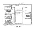
- an electrosurgical instrumentfor treating the skin of a patient.
- the instrumentgenerally comprises a shaft having a shaft distal end and a shaft proximal end, and an electrode assembly disposed at the shaft distal end.
- the shaft distal endis adapted for penetrating the skin to a subcutaneous location.
- the shaftmay comprise a narrow diameter stainless steel rod, e.g., having dimensions similar to those of a hypodermic needle.
- the electrode assemblycomprises an electrically insulating electrode support, an active electrode terminal on the electrode support, and a return electrode disposed proximal to the active electrode terminal.
- the shaft distal endis adapted for transformation (or interconversion) between a linear configuration, adapted for penetrating the skin to a subcutaneous location, and a curved configuration, adapted for guiding the active electrode from the subcutaneous location to a target location within the dermis.
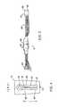
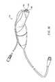
- FIG. 1is a perspective view of an electrosurgical system for treating a patient's skin including an electrosurgical generator and an electrosurgical probe or handpiece;
- FIG. 2is a perspective view of one embodiment of an electrosurgical probe constructed according to the principles of the present invention
- FIGS. 3A-3Care exploded, isometric views of the probe of FIG. 2 ;
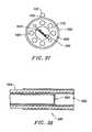
- FIG. 4is an end view of the distal tip of the probe, illustrating an electrode support with a plurality of electrode terminals
- FIG. 5illustrates the electrical connections and the electrode support of the handpiece in greater detail
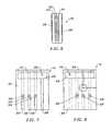
- FIG. 6is an end view of an exemplary electrode support comprising a multi-layer wafer with plated conductors for electrodes;
- FIGS. 7 and 8are side views of the electrode support of FIG. 7 ;
- FIGS. 9A , 10 A, 11 A, 12 A, and 13are side views of the individual wafer layers of the electrode support
- FIGS. 9B , 10 B, 11 B, and 12 Bare cross-sectional views of the individual wafer layers
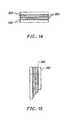
- FIGS. 14 and 15illustrate an alternative multi-layer wafer design according to the present invention
- FIG. 16Aillustrates a method for treating the outer layer of a patient's skin in a skin resurfacing procedure, wherein an outer layer of epidermis is removed or ablated and the collagen fibers in the underlying dermis are contracted;
- FIG. 16Billustrates a method for treating the outer layer of a patient's skin in a skin resurfacing procedure with an electrosurgical probe having a single, active electrode terminal;
- FIG. 17illustrates a method of skin resurfacing wherein the epidermal layer is separated from the dermis, and then removed by wiping away the separated layer;
- FIGS. 18A and 18Billustrate a method for treating a vascular lesion
- FIG. 19illustrates a method of removing scalp tissue and/or hair according to the present invention
- FIG. 20is a cross-sectional view of an alternative electrosurgical probe for applying high frequency voltage to tissue layers on the skin;
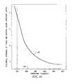
- FIG. 21is a graph illustrating the electrical impedance of tissue and isotonic saline with operating frequency
- FIG. 22illustrates another embodiment of the probe of the present invention, incorporating additional electrodes sized for contraction of tissue
- FIG. 23illustrates another embodiment of the probe of the present invention, specifically designed for creating incisions in external skin surfaces
- FIGS. 24-26illustrates a method according to the present invention for removing fatty tissue under the eyelids to treat “baggy eyelids” syndrome
- FIG. 27is a detailed end view of an electrosurgical probe having an elongate, linear array of electrode terminals suitable for use in surgical cutting;
- FIG. 28is a detailed view of a single electrode terminal having a flattened end at its distal tip
- FIG. 29is a detailed view of a single electrode terminal having a pointed end at its distal tip
- FIG. 30is a perspective view of another embodiment of an electrosurgical probe for use in dermatology procedures.
- FIG. 31is a detailed view of the distal portion of yet another electrosurgical probe according to the present invention.
- FIG. 32is a perspective view of another electrosurgical system incorporating a power supply, an electrosurgical probe and a supply of electrically conductive fluid for delivering the fluid to the target site;
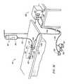
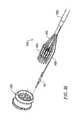
- FIG. 33is a side view of another electrosurgical probe according to the present invention incorporating aspiration electrodes for ablating aspirated tissue fragments and/or tissue strands, such as adipose tissue;
- FIG. 34is an end view of the probe of FIG. 33 ;
- FIG. 35is an exploded view of a proximal portion of the electrosurgical probe
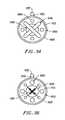
- FIGS. 36-38illustrate alternative probes according to the present invention, incorporating aspiration electrodes
- FIG. 39illustrates a method for removing fatty tissue in the abdomen, groin or thighs region of a patient according to the present invention
- FIG. 40illustrates a method for removing fatty tissue in the head and neck region of a patient according to the present invention
- FIG. 41is a block diagram representing an electrosurgical system, according to one aspect of the invention.
- FIG. 42is a block diagram representing an electrosurgical system, according to the instant invention.
- FIG. 43is a partial sectional view of an electrosurgical probe, according to one embodiment of the invention.
- FIGS. 44A-Ceach show a side view of the working end of an electrosurgical probe having a distal electrode assembly, according to three different embodiments of the invention.
- FIGS. 45A and 45Bshow an electrosurgical probe in a linear configuration and a curved configuration, respectively, according to the invention.
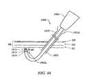
- FIG. 46illustrates subcutaneous access of the underside of the skin by a probe working end introduced via an introducer device, according to one embodiment of the invention
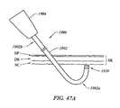
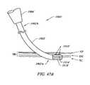
- FIGS. 47A and 47Beach illustrate subcutaneous access of the underside of the skin by a probe working end, according to two different embodiments of the invention.
- FIGS. 48A-Crepresent treatment of a wrinkle in the skin via direct insertion of an electrosurgical instrument into a sub-epidermal layer, according to one embodiment of the invention
- FIGS. 49A-Crepresent treatment of a wrinkle in the skin via subcutaneous access of the underside of the skin by an electrosurgical instrument, according to another embodiment of the invention.
- FIG. 50schematically represents a series of steps involved in a method for electrosurgically treating the skin of a patient, according to one embodiment of the invention.
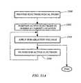
- FIGS. 51A and 51Beach schematically represent a series of steps involved in a method for electrosurgically removing wrinkles in the skin of a patient, according to two different embodiments of the invention.
- the present inventionprovides systems and methods for selectively applying energy to a target location within or on a patient's body, particularly including procedures on an external body surface, such as epidermal and dermal tissues in the skin, or the underlying subcutaneous tissue.
- the present inventionalso provides methods and apparatus for removing fatty or adipose tissue underlying the epidermal and dermal layers of the skin, such as liposuction, abdominoplasties, or other lipectomy procedures.
- the present inventionalso relates to procedures for skin tissue cutting, ablation, incising or removal in the epidermis or dermis, e.g., the removal of pigmentations, vascular lesions (e.g., leg veins), scars, tattoos, etc., and for other surgical procedures on the skin, such as tissue rejuvenation, skin shrinkage, blepharoplasty, browlifts, cosmetic surgery, wrinkle removal, face-lifts and neck-lifts, as well as hair removal and/or hair transplant procedures.
- the present inventionis also concerned with shrinkage of skin by electrosurgical treatment of the underside of the skin, e.g., at the site of a liposuction or face-lift procedure.
- the systems and methodscan be applied equally well to procedures involving other tissues of the body, as well as to other procedures including open surgery, arthroscopic surgery, laparoscopic surgery, thoracoscopic surgery, and other endoscopic surgical procedures.
- the present inventionapplies high frequency (RF) electrical energy to one or more electrode terminals underlying an external body surface, such as the outer surface of the skin, to soften and/or ablate fatty tissue in order to aspirate the fatty tissue from the patient's body.
- RFhigh frequency
- the present inventionmay be used to: (1) volumetrically remove the fatty tissue (i.e., ablate or effect molecular dissociation of adipose tissue); (2) decouple or soften fatty tissue from adjacent tissue so that the fatty tissue can be more easily aspirated; (3) shrink and tighten the skin by controlled heating of the dermis; (4) induce localized collagen deposition in the dermis to reduce or remove skin wrinkles; (5) shrink or contract collagen-containing connective tissue; and/or (6) coagulate blood vessels underlying the surface of the skin.
- the fatty tissuei.e., ablate or effect molecular dissociation of adipose tissue
- decouple or soften fatty tissue from adjacent tissueso that the fatty tissue can be more easily aspirated
- shrink and tighten the skin by controlled heating of the dermis(4) induce localized collagen deposition in the dermis to reduce or remove skin wrinkles
- (5) shrink or contract collagen-containing connective tissueand/or (6) coagulate blood vessels underlying
- the present inventionapplies high frequency (RF) electrical energy to one or more electrode terminals underlying, within, or adjacent to the skin, in order to contract collagen fibers within the dermis.
- the RF energyheats the tissue in a controlled manner, either directly by virtue of the electrical current flowing therethrough, or indirectly by exposing the tissue to fluid heated by the RF energy, to elevate the tissue temperature from normal body temperatures (e.g., 37° C.) to a temperature in the range of from about 45° C. to 90° C., and preferably in the range of from about 60° C. to 70° C.
- Thermal shrinkage of mammalian collagenoccurs within a temperature range of from about 60° C. to 70° C.
- Deak, G., et al.“The Thermal Shrinkage Process of Collagen Fibres as Revealed by Polarization Optical Analysis of Topooptical Staining Reactions,” Acta Morphologica Acad. Sci. of Hungary, Vol. 15(2), pp 195-208, 1967).
- previously reported researchhas attributed thermal shrinkage of collagen to the cleaving of the internal stabilizing cross-linkages within the collagen matrix (Deak, G., et al., ibid.).
- tissueis ablated or removed through molecular dissociation or disintegration of tissue components (i.e., by breaking the molecular bonds of the tissue components).
- a high frequency voltageis applied between one or more electrode terminal(s) and one or more return electrode(s) to develop high electric field intensities in the vicinity of the target tissue site.
- the high electric field intensitieslead to electric field induced molecular breakdown of target tissue through molecular dissociation (rather than thermal evaporation or carbonization).
- Applicantbelieves that the tissue structure is volumetrically removed through molecular disintegration of larger organic molecules into smaller molecules and/or atoms, such as hydrogen, oxides of carbon, hydrocarbons and nitrogen compounds. This molecular disintegration completely removes the tissue structure, as opposed to dehydrating the tissue material by the removal of liquid within the cells of the tissue, as is typically the case with electrosurgical desiccation and vaporization processes of the prior art.
- the high electric field intensitiesmay be generated by applying a high frequency voltage that is sufficient to vaporize an electrically conductive fluid over at least a portion of the electrode terminal(s) in the region between the distal tip of the electrode terminal(s) and the target tissue.
- the electrically conductive fluidmay be a liquid, such as isotonic saline, delivered to the target site, or a viscous fluid, such as a gel, that is located at the target site. In the latter embodiment, the electrode terminal(s) are submersed in the electrically conductive gel during the surgical procedure.
- the vapor layer or vaporized regionSince the vapor layer or vaporized region has a relatively high electrical impedance, it increases the voltage differential between the electrode terminal tip and the tissue and causes ionization within the vapor layer due to the presence of an ionizable species (e.g., sodium when isotonic saline is the electrically conductive fluid). This ionization, under optimal conditions, induces the discharge of energetic electrons and photons from the vapor layer and to the surface of the target tissue. This energy may be in the form of energetic photons (e.g., ultraviolet radiation), energetic particles (e.g., electrons) or a combination thereof. A more detailed description of this phenomenon can be found in commonly assigned U.S. Pat. No. 5,683,366 the complete disclosure of which is incorporated herein by reference.
- energetic photonse.g., ultraviolet radiation
- energetic particlese.g., electrons
- the temperature of the electrode terminal(s)can be carefully controlled such that sufficient thermal energy is transferred to these underlying layers to contract the collagen connective tissue.
- the thermal energymay be transferred directly through RF current that passes through and resistively heats the underlying tissue layers, or it may be transferred indirectly by heating the electrically conductive fluid, and allowing the heated fluid to contact the underlying layers after the epidermal layers have been removed.
- one or more electrode terminalsare brought into close proximity to tissue at a target site, and the power supply is activated in the ablation mode such that sufficient voltage is applied between the electrode terminals and the return electrode to volumetrically remove the tissue through molecular dissociation, as described below.
- the power supplyis activated in the ablation mode such that sufficient voltage is applied between the electrode terminals and the return electrode to volumetrically remove the tissue through molecular dissociation, as described below.
- vessels within the tissuewill be severed. Smaller vessels will be automatically sealed with the system and method of the present invention. Larger vessels, and those with a higher flow rate, such as arterial vessels, may not be automatically sealed in the ablation mode. In these cases, the severed vessels may be sealed by activating a control (e.g., a foot pedal) to reduce the voltage of the power supply into the coagulation (sub-ablation) mode.
- a controle.g., a foot pedal
- the electrode terminalsmay be pressed against the severed vessel to provide sealing and/or coagulation of the vessel.
- a coagulation electrode located on the same or a different instrumentmay be pressed against the severed vessel.
- the present inventionis also useful for ablating, cutting or softening tissue around nerves, such as cranial nerves, e.g., facial nerves, vestibulocochlear nerves and the like.
- nervessuch as cranial nerves, e.g., facial nerves, vestibulocochlear nerves and the like.
- One of the significant drawbacks with prior art RF devices and lasersis that these devices do not differentiate between the target tissue and the surrounding nerves or bone. Therefore, the surgeon must be extremely careful during these procedures to avoid damage to the nerves within and around the target site.
- the CoblationTM process for removing tissueresults in extremely small depths of collateral tissue damage as discussed above. This allows the surgeon to remove, soften or cut tissue close to a nerve without causing collateral damage to the nerve fibers.
- Nervesusually comprise a connective tissue sheath, or epineurium, enclosing the bundles of nerve fibers, each bundle being surrounded by its own sheath of connective tissue (the perineurium) to protect these nerve fibers.
- the outer protective tissue sheath or epineuriumtypically comprises a fatty material having substantially different electrical properties than the normal target tissue, such as collagen-containing connective tissue.
- the system of the present inventionmeasures the electrical properties of the tissue at the tip of the probe with one or more sensing electrode(s). These electrical properties may include electrical conductivity at one, several, or a range of frequencies (e.g., in the range from 1 kHz to 100 MHz), dielectric constant, capacitance, or combinations of these.
- an audible signalmay be produced when the sensing electrode(s) at the tip of the probe detects the fatty material surrounding a nerve, or direct feedback control can be provided to only supply power to the electrode terminal(s), either individually or to the complete array of electrodes, if and when the tissue encountered at the tip or working end of the probe is normal tissue based on the measured electrical properties.
- the Coblation® mechanism of the present inventioncan be manipulated to ablate or cut certain tissue structures, while having little effect on other tissue structures.
- the present inventionuses a technique of vaporizing electrically conductive fluid to form a plasma layer or pocket around the electrode terminal(s), and then inducing the discharge of energy from this plasma or vapor layer to break the molecular bonds of the tissue structure. Based on initial experiments, applicants believe that the free electrons within the ionized vapor layer are accelerated in the high electric fields near the electrode tip(s).
- the electron mean free pathincreases to enable subsequently injected electrons to cause impact ionization within these regions of low density (i.e., vapor layers or bubbles).
- Energy evolved by the energetic electronse.g., 4 to 5 eV
- the energy evolved by the energetic electronsmay be varied by adjusting a variety of factors, such as: the number of electrode terminals; electrode size and spacing; electrode surface area; asperities and sharp edges on the electrode surfaces; electrode materials; applied voltage and power; current limiting means, such as inductors; electrical conductivity of the fluid in contact with the electrodes; density of the fluid; and other factors. Accordingly, these factors can be manipulated to control the energy level of the excited electrons. Since different tissue structures have different molecular bonds, the present invention can be configured to break the molecular bonds of certain tissue, while having too low an energy to break the molecular bonds of other tissue.
- fatty tissuee.g., adipose tissue
- fatty tissuee.g., adipose tissue
- factors such as applied voltage and powermay be adjusted such that the target tissue (e.g., adipose tissue, dermal tissue) may be ablated or modified according to a particular procedure.
- the present inventionmay be used to effectively ablate cells to release the inner fat content in a liquid form.
- the present inventionalso provides systems, apparatus and methods for selectively removing tumors, e.g., facial tumors, or other undesirable body structures while minimizing the spread of viable cells from the tumor.
- Conventional techniques for removing such tumorsgenerally result in the production of smoke in the surgical setting, termed an electrosurgical or laser plume, which can spread intact, viable bacterial or viral particles from the tumor or lesion to the surgical team or to other portions of the patient's body.
- This potential spread of viable cells or particleshas resulted in increased concerns over the proliferation of certain debilitating and fatal diseases, such as hepatitis, herpes, HIV and papillomavirus.
- high frequency voltageis applied between the electrode terminal(s) and one or more return electrode(s) to volumetrically remove at least a portion of the tissue cells in the tumor through the dissociation or disintegration of organic molecules into non-viable atoms and molecules.
- the present inventionconverts the solid tissue and cells into non-condensable gases that are no longer intact or viable, and thus, not capable of spreading viable tumor particles to other portions of the patient's brain or to the surgical staff.
- the high frequency voltageis preferably selected to effect controlled removal of these tissues and cells, while minimizing substantial tissue necrosis to surrounding or underlying tissue.
- the electrosurgical instrumentwill comprise a shaft or a handpiece having a proximal end and a distal end which supports one or more electrode terminal(s).
- the shaft or handpiecemay assume a wide variety of configurations, with the primary purpose being to mechanically support the active electrode and permit the treating physician to manipulate the electrode from a proximal end of the shaft.
- the shaftwill have any suitable length and diameter that would facilitate handling the instrument by the surgeon.
- the shaftwill preferably have a distal end suitable for delivery through a percutaneous penetration in the patient's skin.
- the present inventionmay use a single active electrode terminal or an electrode array distributed over a contact surface of an instrument.
- the electrode arrayusually includes a plurality of independently current-limited and/or power-controlled electrode terminals to apply electrical energy selectively to the target tissue while limiting the unwanted application of electrical energy to the surrounding tissue and environment resulting from power dissipation into surrounding electrically conductive liquids, such as blood, normal saline, electrically conductive gel, and the like.
- the electrode terminalsmay be independently current-limited by isolating the terminals from each other and connecting each terminal to a separate power source that is isolated from the other electrode terminals.
- the electrode terminalsmay be connected to each other at either the proximal or distal ends of the probe to form a single wire that couples to a power source.
- the electrode terminal(s)are preferably supported within or by an inorganic insulating support positioned near the distal end of the instrument shaft.
- the return electrodemay be located on the instrument shaft, on another instrument, or on the external surface of the patient (i.e., a dispersive pad).
- a dispersive padi.e., a dispersive pad.
- the return electrodeis preferably either integrated with the instrument body, or another instrument located in close proximity to the distal end of the instrument.
- the proximal end of the instrumentwill include the appropriate electrical connections for coupling the return electrode(s) and the electrode terminal(s) to a high frequency power supply, such as an electrosurgical generator.
- the current flow path between the electrode terminals and the return electrode(s)may be generated by submerging the tissue site in an electrical conducting fluid (e.g., within a viscous fluid, such as an electrically conductive gel) or by directing an electrically conductive fluid along a fluid path to the target site (i.e., a liquid, such as isotonic saline, or a gas, such as argon).
- the conductive gelmay also be delivered to the target site to achieve a slower more controlled delivery rate of conductive fluid.
- the viscous nature of the gelmay allow the surgeon to more easily contain the gel around the target site (e.g., rather than attempting to contain isotonic saline).
- a liquid electrically conductive fluide.g., isotonic saline
- a liquid electrically conductive fluidmay be used to concurrently “bathe” the target tissue surface to provide an additional means for removing any tissue, and to cool the region of the target tissue ablated in the previous moment.
- the power supplymay include a fluid interlock for interrupting power to the electrode terminal(s) when there is insufficient conductive fluid around the electrode terminal(s). This ensures that the instrument will not be activated when conductive fluid is not present, minimizing the tissue damage that may otherwise occur.
- a fluid interlockcan be found in commonly assigned, co-pending U.S. application Ser. No. 09/058,336, filed Apr. 10, 1998, the complete disclosure of which is incorporated herein by reference.
- the system of the present inventionmay include one or more suction or aspiration lumen(s) in the instrument, or on another instrument, coupled to a suitable vacuum source for aspirating fluids from the target site.
- the inventionmay include one or more aspiration electrode(s) coupled to the distal end of the suction lumen for ablating, or at least reducing the volume of, non-ablated tissue fragments that are aspirated into the lumen.
- the aspiration electrode(s)function mainly to inhibit clogging of the suction lumen that may otherwise occur as larger tissue fragments are drawn therein.
- the aspiration electrode(s)may be different from the ablation electrode terminal(s), or the same electrode(s) may serve both functions.
- a more complete description of instruments incorporating aspiration electrode(s)can be found in commonly assigned, U.S. Pat. No. 6,190,381, the complete disclosure of which is incorporated herein by reference.
- each individual electrode terminal in the electrode arrayis electrically insulated from all other electrode terminals in the array of an electrosurgical instrument, and each terminal is connected to a power source which is isolated from each of the other electrode terminals in the array, or to circuitry which limits or interrupts current flow to the electrode terminal when low resistivity material (e.g., blood, electrically conductive saline irrigant or electrically conductive gel) causes a lower impedance path between the return electrode and the individual electrode terminal.
- the isolated power sources for each individual electrode terminalmay be separate power supply circuits having internal impedance characteristics which limit power to the associated electrode terminal when a low impedance return path is encountered.
- the isolated power sourcemay be a user selectable constant current source.
- a single power sourcemay be connected to each of the electrode terminals through independently actuatable switches, or by independent current limiting elements, such as inductors, capacitors, resistors and/or combinations thereof.
- the current limiting elementsmay be provided in the probe, connectors, cable, controller or along the conductive path from the controller to the distal tip of the probe.
- the resistance and/or capacitancemay occur on the surface of the active electrode terminal(s) due to oxide layers which form selected electrode terminals (e.g., titanium or a resistive coating on the surface of metal, such as platinum).
- the tip region of the probemay comprise many independent electrode terminals designed to deliver electrical energy in the vicinity of the tip.
- the selective application of electrical energy to the conductive fluidis achieved by connecting each individual electrode terminal and the return electrode to a power source having independently controlled or current limited channels.
- the return electrodemay be a tubular member of conductive material, proximal to the electrode array at the tip, which also serves as a conduit for the supply of the electrically conductive fluid between the active and return electrodes.
- the application of high frequency voltage between the return electrode and the electrode arrayresults in the generation of high electric field intensities at the distal tips of the electrode terminals with conduction of high frequency current from each individual electrode terminal to the return electrode.
- the current flow from each individual electrode terminal to the return electrodeis controlled by either active or passive means, or a combination thereof, to deliver electrical energy to the surrounding conductive fluid while minimizing energy delivery to surrounding (non-target) tissue.
- the application of a high frequency voltage between the return electrode and the electrode array for appropriate time intervalseffects heating of the conductive fluid and contraction of the target tissue.
- the tissue volume over which energy is dissipatedi.e., a high current density exists
- the tissue volume over which energy is dissipatedmay be precisely controlled, for example, by the use of a multiplicity of small electrode terminals whose effective diameters or principal dimensions range from about 10 mm to 0.01 mm, preferably from about 5 mm to 0.05 mm, and more preferably from about 3 mm to 0.1 mm.
- Electrode areas for both circular and non-circular terminalswill have a contact area (per electrode terminal) below 25 mm 2 , preferably being in the range from 0.0001 mm 2 to 1 mm 2 , and more preferably from 0.005 mm 2 to 0.5 mm 2 .
- the circumscribed area of the electrode arrayis in the range from 0.25 mm 2 to 75 mm 2 , preferably from 0.5 mm 2 to 40 mm 2 , and will usually include at least two isolated electrode terminals and preferably about three electrode terminals.
- the arraymay include more than three electrode terminals (e.g., 50 or more electrode terminals) disposed over the distal contact surfaces on the shaft.
- the use of small diameter electrode terminalsincreases the electric field intensity and reduces the extent or depth of tissue heating as a consequence of the divergence of current flux lines which emanate from the exposed surface of each electrode terminal.
- the electrode terminal(s)are formed over a tissue treatment surface on the shaft of the electrosurgical probe.
- the return electrode surfacemay be recessed relative to the distal end of the probe and may be recessed within a fluid conduit provided for the introduction of electrically conductive fluid to the site of the target tissue and electrode terminal(s).
- the area of the tissue treatment surfacecan vary widely, and the tissue treatment surface can assume a variety of geometries, with particular areas and geometries being selected for specific applications.
- Active electrode surfacescan have areas in the range from 0.25 mm 2 to 75 mm 2 , usually being from about 0.5 mm 2 to 40 mm 2 .
- the geometriescan be planar, concave, convex, hemispherical, conical, linear “in-line” array, or virtually any other regular or irregular shape.
- the active electrode(s) or electrode terminal(s)will be formed at the distal tip of the electrosurgical probe shaft, frequently being planar, disk-shaped, or hemispherical surfaces for use in reshaping procedures or being linear arrays for use in cutting.
- the active electrode(s)may be formed on lateral surfaces of the electrosurgical probe shaft (e.g., in the manner of a spatula), facilitating access to certain body structures in endoscopic or percutaneous procedures.
- the electrode arraycomprises a plurality of substantially elongate electrode terminals spaced on the contact surface of the shaft.
- the contact surfaceis an electrically insulating electrode support member extending from the shaft of the probe.
- the elongate electrode terminalswill typically have a length of about 0.5 to 30 mm, preferably about 1 to 15 mm, and more preferably about 3 to 7 mm.
- the width of the elongate electrode terminalsis usually about 0.01 to 2 mm, preferably about 0.05 to 1 mm, and more preferably about 0.1 to 0.5 mm.
- the elongate electrode terminalswill be spaced from each other by a distance of about 0.05 to 4 mm, preferably about 0.1 mm to 2 mm.
- the arraymay comprise one electrode terminal or over 50 electrode terminals, applicant has found that two to ten electrode terminals provides a substantially uniform application of energy to the tissue at the treatment site.
- the electrode supportcomprises a plurality of wafer layers bonded together, e.g., by a glass adhesive or the like.
- the wafer layerseach have conductive strips printed thereon to form the electrode terminal(s) and the return electrode(s).
- the proximal end of the wafer layerswill have a number of holes extending from the conductor strips to an exposed surface of the wafer layers for connection to electrical conductor lead traces in the electrosurgical probe or handpiece.
- the wafer layerspreferably comprise a ceramic material, such as alumina, and the electrode will preferably comprise a metallic material, such as gold, platinum, palladium, tungsten, silver, or their alloys, and the like. Suitable multilayer ceramic electrodes are commercially available from e.g., VisPro Corporation of Beaverton, Oreg.
- the electrically conductive fluidshould have a threshold conductivity to provide a suitable conductive path between the return electrode and the electrode terminal(s).
- the electrical conductivity of the fluid(in units of milliSiemens per centimeter or mS/cm) will usually be greater than 0.2 mS/cm, preferably will be greater than 2 mS/cm, and more preferably greater than 10 mS/cm.
- the electrically conductive fluidis isotonic saline, which has a conductivity of about 17 mS/cm.
- the fluidmay be an electrically conductive gel or spray, such as a saline electrolyte gel, a conductive ECG spray, an electrode conductivity gel, an ultrasound transmission or scanning gel, or the like.
- Suitable gels or spraysare commercially available from Graham-Field, Inc. of Hauppauge, N.Y.
- other electrically conductive fluidsmay be used, as described in U.S. Provisional Patent Application No. 60/098,122, filed Aug. 27, 1998, the complete disclosure of which is incorporated herein by reference.
- the electrode support and the fluid outletmay be recessed from an outer surface of the probe or handpiece to confine the electrically conductive fluid to the region immediately surrounding the electrode support.
- the shaftmay be shaped so as to form a cavity around the electrode support and the fluid outlet. This helps to assure that the electrically conductive fluid will remain in contact with the electrode terminal(s) and the return electrode(s) to maintain the conductive path therebetween. In addition, this will help to maintain a vapor or plasma layer between the electrode terminal(s) and the tissue at the treatment site throughout the procedure, which reduces the thermal damage that might otherwise occur if the vapor layer were extinguished due to a lack of conductive fluid.
- the electrically conductive fluidalso helps maintain the tissue temperature as low as possible during the procedure.
- the voltage applied between the return electrode and the electrode arraywill be at high or radio frequency (RF), typically between about 5 kHz and 20 MHz, usually being between about 30 kHz and 2.5 MHz, preferably being between about 50 kHz and 500 kHz, more preferably less than 350 kHz, and often between about 100 kHz and 200 kHz.
- RFradio frequency
- the RMS (root mean square) voltage appliedwill usually be in the range from about 5 volts RMS to 1000 volts RMS, typically being in the range of from about 10 volts RMS to 500 volts RMS, depending on the electrode terminal size, the operating frequency and the operation mode of the particular procedure or desired effect on the tissue (i.e., contraction, coagulation or ablation).
- the peak-to-peak voltagewill be in the range of 10 to 2000 volts, usually in the range of 20 to 1200 volts, and often in the range of from about 40 to 800 volts (again, depending on the electrode size, the operating frequency and the operation mode).
- the frequency of the output voltage of the generatorcan be selected to control the depth of tissue heating.
- the electrical impedance of tissueis known to decrease with increasing frequency due to the electrical properties of cell membranes which surround electrically conductive cellular fluid.
- the electrical impedance of tissue to current at a frequency of 100 kHzis on the order of four times larger than at a frequency of 450 to 500 kHz.
- the current flux linestend to penetrate less deeply resulting in a smaller depth of tissue heating.
- This principle of operation of the present inventioncan be used to advantage in applications where the depth of tissue heating is to be maintained small (e.g., in the range of from about 0.2 to 0.5 mm).
- the operating frequencyshould be below 350 kHz for applications requiring shallow depths of tissue heating (e.g., less than 1.5 mm).
- a higher output voltage frequencymay be used.
- a higher operating frequencymay be used (e.g., 500 kHz).
- the diameter of the electrode terminals and/or the spacing between the outer perimeter of the electrode terminals and the electrode support membermay be selected to increase the depth of current penetration.
- increasing the distance between the outer perimeter of the support member and the electrode terminalswill increase the depth of heating for a given operating frequency.
- the voltageis usually delivered in a series of voltage pulses or alternating current of time varying voltage amplitude with a sufficiently high frequency (e.g., on the order of 5 kHz to 20 MHz) such that the voltage is effectively applied continuously (as compared with e.g., lasers claiming small depths of necrosis, which are generally pulsed at about 10 Hz to 20 Hz).
- the duty cyclei.e., cumulative time in any one-second interval that energy is applied
- the preferred power source of the present inventiondelivers a high frequency current selectable to generate average power levels ranging from several milliwatts to tens of watts per electrode, depending on the volume of target tissue being treated, the total number of electrode(s), and/or the maximum allowed temperature selected for the probe tip.
- the power sourceallows the user to select the voltage level according to the specific requirements of a particular arthroscopic surgery, cosmetic surgery, dermatological procedure, ophthalmic procedures, open surgery or other endoscopic surgery procedure.
- a description of a suitable power sourcecan be found in U.S. Provisional Patent Application No. 60/062,997, filed on Oct. 23, 1997, the complete disclosure of which has been previously incorporated herein by reference.
- the power sourcemay be current limited or otherwise controlled so that undesired heating of the target tissue or surrounding (non-target) tissue does not occur.
- current limiting inductorsare placed in series with each independent electrode terminal, where the inductance of the inductor is in the range of 10 uH to 50,000 uH, depending on the electrical properties of the target tissue, the size of the electrode terminal(s), the desired tissue heating rate and the operating frequency.
- capacitor-inductor (LC) circuit structuresmay be employed, as described previously in PCT application No. PCT/US94/05168, the complete disclosure of which is incorporated herein by reference. Additionally, current limiting resistors may be selected.
- these resistorswill have a large positive temperature coefficient of resistance so that, as the current level begins to rise for any individual electrode terminal in contact with a low resistance medium (e.g., saline irrigant or conductive gel), the resistance of the current limiting resistor increases significantly, thereby minimizing the power delivery from said electrode terminal into the low resistance medium (e.g., saline irrigant or conductive gel).
- a low resistance mediume.g., saline irrigant or conductive gel
- the inventionis not limited to electrically isolated electrode terminals, or even to a plurality of electrode terminals.
- the array of active electrode terminalsmay be connected to a single lead that extends through the probe shaft to a power source of high frequency current.
- the probemay incorporate a single electrode that extends directly through the probe shaft or is connected to a single lead that extends to the power source.
- an electrosurgical system 11generally comprises an electrosurgical handpiece or probe 10 connected to a power supply 28 for providing high frequency voltage to a target site, and a fluid source 21 for supplying electrically conductive fluid 50 to probe 10 .
- Probe 10generally includes a proximal handle 12 and a distal tip 13 having an electrode support member 70 with one or an array of electrode terminals 58 and one or more return electrodes 100 , 102 (see FIGS. 2 , 4 and 5 ) disposed on the support member 70 .
- a connecting cable 34has a connector 26 for electrically coupling the electrodes in probe 10 to power supply 28 .
- the electrode terminals 58are electrically isolated from each other, and each of the terminals 58 is connected to an active or passive control network within power supply 28 by means of a plurality of individually insulated conductors (not shown).
- a fluid supply tube 15is connected to a fluid tube 110 of probe 10 for supplying electrically conductive fluid 50 to a distal tip 13 (see FIGS. 16A , 16 B, and 17 ).
- Power supply 28has an operator controllable voltage level adjustment 30 to change the applied voltage level, which is observable at a voltage level display 32 .
- Power supply 28also includes first, second and third foot pedals 37 , 38 , 39 and a cable 36 which is removably coupled to power supply 28 .
- the foot pedals 37 , 38 , 39allow the surgeon to remotely adjust the energy level applied to electrode terminals 58 .
- first foot pedal 37is used to place the power supply into the “ablation” mode and second foot pedal 38 places power supply 28 into the “sub-ablation” or coagulation mode.
- the third foot pedal 39allows the user to adjust the voltage level within the ablation mode.
- a sufficient voltageis applied to the electrode terminals to establish the requisite conditions for molecular dissociation of the tissue (e.g., by vaporizing a portion of the electrically conductive fluid, ionizing the vapor layer, and accelerating charged particles against the tissue).
- the requisite voltage level for ablationwill vary depending on the number, size, shape and spacing of the electrodes, the distance to which the electrodes extend from the support member, etc.
- voltage level adjustment 30 or third foot pedal 39may be used to adjust the voltage level to adjust the degree or aggressiveness of the ablation.
- the power supply 28applies a low enough voltage to one or more electrode terminals (or one or more coagulation electrodes) to avoid vaporization of the electrically conductive fluid, formation of a plasma and subsequent molecular dissociation of the tissue.
- the surgeonmay automatically toggle the power supply between the ablation and sub-ablation modes by alternatively stepping on foot pedals 37 , 38 , respectively. This allows the surgeon to quickly move between coagulation and ablation in situ, without having to remove his/her concentration from the surgical field or without having to request an assistant to switch the power supply.
- the probetypically will simultaneously seal and/or coagulate small severed vessels within the tissue.
- an exemplary electrosurgical probe 10comprises a shaft or disposable tip 13 removably coupled to a proximal handle 12 , and an electrically insulating electrode support member 70 extending from tip 13 for supporting a plurality of electrode terminals 58 (see FIGS. 2 and 5 ).
- Tip 13 and handle 12typically comprise a plastic material that is easily molded into a suitable shape for handling by the surgeon.
- handle 12defines an inner cavity 72 that houses the electrical connections 74 (discussed below in reference to FIG. 5 ), and provides a suitable interface for connection to electrical connecting cable 34 (see FIG. 1 ).
- handle 12is constructed of a steam autoclavable plastic or metal (e.g., polyethylether ketone, or a stable metal alloy containing aluminum and/or zinc so that it can be re-used by sterilizing handle 12 between surgical procedures.
- a steam autoclavable plastic or metale.g., polyethylether ketone, or a stable metal alloy containing aluminum and/or zinc so that it can be re-used by sterilizing handle 12 between surgical procedures.
- High service temperature materialsare preferred, such as a silicone cable jacket and a polyetherimide or ULTEM® handpiece that can withstand a repeated exposure to high temperatures.
- tip 13preferably comprises first and second housing halves 200 , 202 that snap fit together, and form a recess 204 therebetween for holding electrode support member 70 within the tip 13 .
- Electrode support member 70extends from the distal end of tip 13 (usually by about 0.5 to 20 mm), and provides support for a plurality of electrically isolated electrode terminals 58 and one or more return electrodes 100 , 102 (see FIG. 4 ).
- electrode support member 70may be recessed from the distal end of tip 13 to help confine the electrically conductive fluid around the electrode terminals 58 during the surgical procedure, as discussed above.
- Electrode support member 70has a substantially planar tissue treatment surface 80 that is usually disposed at an angle of about 10° to 90° relative to the longitudinal axis of handle 12 to facilitate handling by the surgeon. In the exemplary embodiment, this function is accomplished by orienting tip 13 at an acute angle relative to the longitudinal axis of handle 12 .
- probe 10includes first and second return electrodes 100 , 102 for completing the current path between electrode terminals 58 and power supply 28 (see FIG. 1 ).
- return electrodes 100 , 102preferably have fluid contact surfaces on either lateral surface 104 , 106 of electrode support member 70 slightly proximal to tissue treatment surface 80 , typically about 0.1 to 2 mm, preferably about 0.2 to 1 mm.
- Return electrodes 100 , 102will usually have an exposed surface area of about 5 mm 2 to 25 mm 2 , preferably about 18 mm 2 to about 20 mm 2 .
- Return electrodes 100 , 102are coupled to a connector 104 (details of this connection are discussed below) that extends to the proximal end of handle 13 , where it is suitably connected to power supply 28 (FIG. 1 ).
- tip 13further includes a proximal hub 206 for supporting a male electrical connector 208 that holds a plurality of wires 210 each coupled to one of the electrode terminals 58 and the return electrodes 100 , 102 on support member 70 (see FIGS. 7-13 for details of the representative support member 70 ).
- a female connector 220 housed within handle 12is removably coupled to male connector 208 , and a plurality of wires 222 extend from female connector 220 through a strain relief 120 to cable 34 . Both sets of wires 210 , 222 are insulated to prevent shorting in the event of fluid ingress into the probe 10 .
- Probe 10will preferably also include an identification element, such as a coded resistor (not shown), for programming a particular voltage output range and mode of operation for the power supply. This allows the power supply to be employed with a variety of different probes for a variety of different applications.
- an identification elementsuch as a coded resistor (not shown), for programming a particular voltage output range and mode of operation for the power supply. This allows the power supply to be employed with a variety of different probes for a variety of different applications.
- probe 10includes a fluid tube 110 ( FIG. 2 ) for delivering electrically conductive fluid to the target site.
- Fluid tube 110is sized to extend through a groove 114 in handle 12 and through an inner cavity 112 (FIG. 3 and FIGS. 3A-3C ) in tip 13 to a distal opening 115 ( FIG. 4 ) located adjacent electrode support member 70 .
- Tube 110extends all the way through inner cavity 112 to opening 115 to eliminate any possible fluid ingress into cavity 112 .
- fluid tube 110includes a proximal connector 111 for coupling tube 110 to an electrically conductive fluid source 21 .
- Probe 10will also include a valve or equivalent structure for controlling the flow rate of the electrically conductive fluid to the target site.
- handle 12comprises a main body 130 coupled between distal hub 118 and strain relief 120 , and a rotatable sleeve 116 around main body 130 .
- Distal hub 118has an opening 119 for receiving proximal hub 206 of tip 13 for removably coupling the tip 13 to the handle 12 .
- Sleeve 116is rotatably coupled to strain relief 120 and distal hub 118 to provide a valve structure for fluid tube 110 .
- fluid tube 110extends through groove 114 from strain relief 120 , through main body 130 and distal hub 118 to tip 13 . Rotation of sleeve 116 will impede, and eventually obstruct, the flow of fluid through tube 110 .
- this fluid controlmay be provided by a variety of other input and valve devices, such as switches, buttons, etc.
- the fluid pathmay be directly formed in probe 10 by, for example, a central inner lumen or an annular gap (not shown) within the handle and the tip.
- This inner lumenmay be formed near the perimeter of the probe 10 such that the electrically conductive fluid tends to flow radially inward towards the target site, or the inner lumen may be formed towards the center of probe 10 so that the fluid flows radially outward.
- the electrically conductive fluidmay be delivered from a fluid delivery element (not shown) that is separate from probe 10 . In arthroscopic surgery, for example, a joint cavity will be flooded with isotonic saline and the probe 10 will be introduced into this flooded cavity.
- electrically isolated electrode terminals 58are spaced apart over tissue treatment surface 80 of electrode support member 70 .
- the tissue treatment surface 80has a rectangular cross-sectional shape with a length L in the range of about 0.5 mm to 20 mm (typically about 2 to 10 mm), and a width W in the range from 0.3 mm to 10 mm (typically about 0.5 to 4 mm).
- the individual electrode terminals 58have the dimensions described above, and in one embodiment terminals 58 are substantially flush with tissue treatment surface 80 .
- the electrode terminals 58may protrude slightly outward from surface 80 , typically by a distance from 0 mm to 2 mm, or the electrode terminals may be recessed from this surface.
- the electrode terminals 58may be recessed by a distance from 0.01 mm to 1 mm, preferably 0.01 mm to 0.2 mm.
- the electrode terminalsare axially adjustable relative to the tissue treatment surface so that the surgeon can adjust the distance between the treatment surface and the electrode terminals.
- electrode support member 70preferably comprises a multilayer substrate comprising a suitable high temperature, electrically insulating material, such as ceramic.
- the multilayer substrateis a thin or thick-film hybrid having conductive strips that are adhered to the ceramic wafer layers (e.g., thick-film printed and fired onto or plated onto the ceramic wafers).
- the conductive stripstypically comprise tungsten, gold, nickel, silver, platinum or equivalent materials.
- the conductive stripscomprise gold, and they are co-fired together with the wafer layers to form an integral package.
- the conductive stripsare coupled to external wire connectors by holes or vias that are drilled through the ceramic layers, and plated or otherwise covered with conductive material.
- support member 70comprises five ceramic layers 201 , 203 , 205 , 207 , 209 (see FIGS. 9 A- 13 ), three gold plated electrode terminals 211 , 212 , 214 and first and second gold plated return electrodes 216 , 218 .
- a first ceramic layer 201which is one of the outer layers of support 70 , includes first gold plated return electrode 216 on a lateral surface 220 thereof.
- First ceramic layer 200further includes a gold conductive strip 223 extending from return electrode 216 to the proximal end of the layer 201 for coupling to a lead wire (not shown), and three gold conductive lines 224 , 226 , 228 extending from a mid-portion of the layer 201 to its proximal end.
- Conductive strips 224 , 226 , 228are each coupled to one of the electrode terminals 210 , 212 , 214 by conductive holes or vias 230 , 232 , 234 , respectively. As shown, all three vias 230 , 232 , 234 extend through wafer layer 201 .
- a second wafer layer 203is bonded between the outer wafer layer 201 and a middle wafer layer 205 (FIGS. 11 A and 11 B).
- first electrode terminal 211is attached to the distal surface of second wafer layer 203
- a conductive strip 240extends to via 230 to couple electrode terminal 211 to a lead wire.
- wafer layers 205 and 207FIGS. 11A and 12B ) each have an electrode terminal 212 , 214 , respectively, plated to their distal surfaces, and a conductive strip 242 , 244 , respectively, extending to one of the vias 232 , 234 , respectively.
- another outer wafer layer 209has a second return electrode 218 plated to the lateral surface 250 of layer 209 .
- the second return electrode 218is coupled directly to the first return electrode 216 through a via 252 extending through the entire ceramic substrate.
- FIGS. 14 and 15illustrate an alternative embodiment of the multilayer ceramic wafer, wherein the electrode terminals comprise planar strips 280 that are plated or otherwise bonded between the ceramic wafer layers 282 .
- the electrode terminalscomprise planar strips 280 that are plated or otherwise bonded between the ceramic wafer layers 282 .
- Each of the planar strips 280has a different length, as shown in FIG. 15 , so that the electrode terminals can be electrically isolated from each other, and coupled to lead wires by vias (not shown).
- distal tip 13 of probe 10is positioned such that electrode support 70 is adjacent to the target tissue 302 at the treatment site 300 .
- Electrically conductive fluid 304is delivered through fluid tube 110 ( FIG. 2 ) through distal opening 115 to the treatment site 300 .
- the rate of fluid flowis controlled with rotatable sleeve 116 ( FIG. 3A ) such that the zone between the tissue 302 and electrode support 70 is constantly immersed in the fluid.
- the power supply 28is then turned on and adjusted such that a high frequency voltage is applied between electrode terminal(s) 58 and return electrodes 100 , 102 .
- the electrically conductive fluid 304provides the conduction path (see current flux lines 310 ) between electrode terminal(s) 58 and the return electrodes 100 , 102 on either side of electrode support 70 .
- the high frequency voltageis sufficient to convert the electrically conductive fluid 304 between the target tissue 302 and electrode terminals 58 into an ionized vapor layer 312 or plasma.
- the applied voltage between electrode terminals 58 and the target tissue 302i.e., the voltage gradient across the plasma layer 312
- charged particles 315 in the plasmaviz., electrons
- these charged particles 315gain sufficient energy to cause dissociation of the molecular bonds of tissue components.
- This molecular dissociationis accompanied by the volumetric removal (i.e., ablative sublimation) of tissue and the production of low molecular weight gases 314 , such as oxygen, nitrogen, carbon dioxide, hydrogen and methane.
- gases 314such as oxygen, nitrogen, carbon dioxide, hydrogen and methane.
- the applied voltagewill be sufficient to apply thermal energy to the underlying tissue 320 , but insufficient to ablate or vaporize the tissue.
- This thermal energywill be sufficient to elevate the tissue temperature from normal body temperatures (e.g., 37° C.) to temperatures in the range of from about 45° C. to 90° C., preferably in the range of from about 55° C. to 70° C. and, for the case of skin, and more preferably in the range of about 55° C. to 62° C.
- This temperature elevationcauses contraction of the collagen fibers within the underlying tissue 320 .
- This methodtightens the underlying dermis to remove wrinkles and rejuvenate the skin. In some embodiments, such tightening of the dermis may be performed in conjunction with removal of the surface layer(s) (epidermis) of the skin.
- FIG. 17An alternative method for skin rejuvenation or wrinkle removal is shown in FIG. 17 .
- this methodwhen a voltage is applied between the electrode terminals 58 and the return electrodes 100 , 102 , electric current flows between the electrode terminals 58 and the return electrode 100 , 102 along current flux lines 350 .
- the current flux lines 350flow a short distance, L 4 into the surface of epidermal tissue 352 and through the electrically conductive fluid 354 in the region above the surface of the tissue to complete the current flow path between the electrode terminals 58 and the return electrodes 100 , 102 .
- heating of the epidermal tissue 352occurs in a region 360 below the surface of the tissue 352 .
- This heatingelevates the temperature of the tissue and separates the epidermal tissue layer 352 from the underlying dermis 362 .
- the epidermal tissue layer 352may then be removed by flushing the treatment site, or by brushing away this tissue layer 352 with, for example, a cloth pad, gauze, etc.
- collagenmay be injected into the dermis after the epidermis has been removed to rejuvenate skin that has lost its elasticity.
- the heating from current flux lines 350may be sufficient to elevate the temperature of the tissue 364 in the dermis 362 from normal body temperature (e.g. 37° C.) to a temperature in the range of from about 55° C. to 85° C., preferably in the range of from about 60° C. to 70° C. This heating of the dermis 362 will cause irreversible contraction of the collagen within the dermis.
- FIGS. 18A and 18Billustrate a method for treating a vascular lesion, such as a port wine stain, face vein, birth mark or the like.
- a vascular lesionsuch as a port wine stain, face vein, birth mark or the like.
- an electrosurgical probe 370is placed on or adjacent to the surface of the skin 372 above the blood vessel 374 to be treated.
- a voltageis applied between the active and return electrodes (not shown) in the presence of electrically conductive fluid 376 to ablate or cause molecular dissociation of the tissue adjacent the probe 370 .
- the probewill be axially translated through the deepening hole to the vessel 374 (note that a substantially linear probe shaft is preferred in this embodiment).
- multiple treatment sitesmay be necessary. As shown in FIG. 18B , it is desirable to locate the first treatment site 380 at a downstream point with respect to the flow of blood in the vessel. The surgeon may then sequentially treat the vessel at multiple sites ( 382 , 384 , 386 ) upstream from the first site 380 .
- a strip of hair (not shown) from a donor regionis first excised from the patient.
- the hairmay be excised by removing the tissue around the strip in a similar manner as described above.
- the hemostatic effects of the electrosurgical system of the present inventionresult in minimal bleeding at the donor site.
- the stripis then lifted from the scalp and sutures are used to close the opening.
- One of the probes described aboveare then used to produce incisions 390 in the recipient area 392 .
- the depth and diameter of the incision 390can be accurately controlled.
- the incisionsare preferably formed at an angle to improve the retention of the graft and to form a more cosmetically suitable appearance.
- FIG. 20illustrates an alternative embodiment, where an electrosurgical probe 430 is utilized to remove the surface layers of the epidermis 440 .
- Probe 430includes a shaft 432 coupled to a proximal handle 434 for holding and controlling shaft 432 . Similar to previous embodiments, probe 430 includes an active electrode array 436 at the distal tip of shaft 432 , an annular return electrode 438 extending through shaft 432 and spaced proximally from the active electrode array 436 , and an annular lumen 442 between return electrode 438 and an outer insulating sheath 444 .
- Probe 430further includes a liquid supply conduit 446 attached to handle 434 and in fluid communication with lumen 442 , and a source of electrically conductive fluid (not shown) for delivering the fluid past return electrode 438 to the target site on the epidermis 440 .
- electrode array 436is preferably flush with the distal end of shaft 432 or distally extended from the distal end by a small distance (on the order of 0.005 inches) so as to minimize the depth of ablation.
- the distal end of shaft 432is beveled to improve access and control of probe 430 while treating the epidermal tissue.
- Electrode terminals 458 , 459may be the same size as ablation electrode terminals 58 , larger as shown in FIG. 22 .
- One operating arrangementis to connect electrode terminals 458 , 459 to two poles of a high frequency generator to form a bipolar circuit allowing current to flow between terminals 458 , 459 as shown by current flux lines 460 .
- the electrode terminals 458 , 459are electrically isolated from ablation electrodes 58 .
- the current flux lines 460can be caused to flow below the epidermal layer to effect collagen shrinkage in region 320 as described hereinabove.
- the voltagewill preferably be sufficient to establish high electric field intensities between the active electrode array 436 and the epidermal tissue 440 to thereby induce molecular breakdown or disintegration of several cell layers of the epidermal tissue.
- a sufficient voltagewill be applied to develop a thin layer of vapor within the electrically conductive fluid and to ionize the vaporized layer or region between the active electrode(s) and the target tissue.
- Energy in the form of photons and/or energetic electronsare discharged from the vapor layer to ablate the epidermal tissue, thereby minimizing necrosis of surrounding tissue and underlying cell layers, such as cell structures in the stratum lucidium and/or stratum granulosum.
- FIG. 23illustrates a distal portion of another electrosurgical probe 500 according to the present invention, particularly useful for cutting or creating incisions in an external skin surface.
- Probe 500comprises a support member 502 coupled to a shaft or disposable tip (not shown) as described in previous embodiments.
- Support member 502preferably comprises an inorganic electrically insulating material, such as ceramic, glass or glass-ceramic.
- support member 502may comprise an organic material, such as plastic, because the active electrode 506 and return electrode 508 are both spaced away from support member 502 .
- the high intensity electric fieldsmay be far enough away from support member 502 so as to allow an organic material.
- Electrode assembly 504extends from a distal end of support member 502 , preferably by a distance of about 2 to 20 mm. Electrode assembly 504 comprises a single, active electrode 506 and a return electrode sleeve 508 spaced proximally from active electrode 506 by an insulation member 510 , which preferably comprises an inorganic material, such as ceramic, glass or glass-ceramic. As shown, active electrode 506 preferably tapers to a sharp distal end 512 to facilitate the cutting or incising of tissue. In the exemplary embodiment, active electrode 506 has a proximal diameter of about 0.2 to 20 mm and a distal diameter of less than about 0.2 mm.
- Return electrode 508is spaced from active electrode 506 by a sufficient distance to prevent shorting or arcing therebetween at sufficient voltages to allow the volumetric removal of tissue.
- the distal exposed portion of return electrode 508is spaced about 0.5 to about 5 mm from the proximal exposed portion of active electrode 506 .
- the present inventionis not limited to the particular dimensions and configuration of the electrode assembly 504 described herein, and a variety of different embodiments may be envisioned depending on the surgical application.
- probe 500includes a fluid lumen 520 passing through support member 502 to a distal opening (not shown) at the distal end of support member 502 .
- Fluid lumen 520is coupled to a supply of electrically conductive fluid, such as isotonic saline, or other suitable conductive fluid for delivery of such fluid to the target site.
- the probeis designed such that lumen 520 will be positioned above electrode assembly 504 during use such that the conductive fluid exiting the distal opening of lumen 520 will naturally pass over return electrode 508 and active electrode 506 thereby creating a current path therebetween.
- the conductive fluidwill be sufficient to cover the active electrode 506 such that the conditions for plasma formation can be met, as described in detail above.
- FIGS. 24-26a blepharoplasty procedure for removing fatty tissue underlying a patient's eyelids will now be described according to the present invention.
- a front view of the orbit of the eye 530reveals the important periocular structures relevant to blepharoplasty surgery.
- the two fat compartments of the upper lid, the central and medial compartments 532 , 534are divided by the superior oblique muscle 536 .
- the inferior orbital fatis divided into three compartments, the medial compartment 538 , the lateral fat compartment 539 and the central fat compartment 540 .
- Medial fathas more blood vessels and nerves than the other fat compartments in both the upper and lower eyelid.
- this fatis more sensitive to the application of energy in conventional systems.
- the present inventionis designed to facilitate access to these fat compartments of the upper and lower eyelids such that a portion of the fat therein can be removed to treat “baggy eyelids” syndrome.
- the electrosurgical probe 500is positioned adjacent the target area, in this case the patient's upper eyelid 550 .
- the power supplyis activated such that a high frequency voltage is applied between the active and return electrodes 506 , 508 and electrically conductive fluid 552 is delivered to the target area, either by gravity, pump or other means.
- the surgeonthen positions the tip of the active electrode 506 adjacent to or in contact with the external skin 554 , and translates the tip across the upper eyelid 550 to form an incision 556 therein.
- the high frequency voltageis sufficient to convert the electrically conductive fluid between the target tissue and active electrode 506 into an ionized vapor layer or plasma.
- the surgeonwill typically create an upper incision line 560 and a lower incision line 562 to form a crescent shaped flap of skin 564 between the two incision lines 560 , 562 .
- the flap of skin 564is then removed, either completely or by folding it over with a pair of forceps 568 , to expose the underlying orbital septum 570 .
- the orbital septum 570is then pierced with the electrosurgical probe of the present invention or with conventional tools, such as a scalpel, and the underlying fat is excised, e.g., with forceps or other conventional tools.
- the probe 500may be used to effect hemostasis of any severed blood vessels at the surgical site. Once the desired amount of fat tissue has been removed, the surgeon reattaches the flap of skin 564 and cleans up the surgical site.
- FIG. 27illustrates yet another embodiment designed for cutting of body structures, particularly creating incisions in external skin surfaces.
- the electrode terminals 604are arranged in a linear or columnar array of one of more closely spaced columns so that as the electrodes 604 are moved along the longer axis (denoted by arrow 160 in FIG. 27 ), the current flux lines are narrowly confined at the tip of the electrode terminals 604 and result in a cutting effect in the body structure being treated.
- the current flux lines 660 emanating from the electrode terminals 604pass through the electrically conducting liquid to the return electrode structure 612 located proximal to the probe tip.
- FIGS. 28 and 29alternative geometries are shown for the electrode terminals 604 .
- These alternative electrode geometriesallow the electrical current densities emanating from the electrode terminals 604 to be concentrated to achieve an increased ablation rate and/or a more concentrated ablation effect due to the fact that sharper edges (i.e., regions of smaller radii of curvature) result in higher current densities.
- FIG. 28illustrates a flattened extension of a round wire electrode terminal 604 which results in higher current densities at the edges 680 .
- FIG. 29shows another example in which the electrode terminal 604 is formed into a cone shaped point 682 resulting in higher current densities at the tip of the cone.
- FIG. 30illustrates yet another embodiment of a probe 710 designed for cutting or incising tissue.
- the electrically isolated electrode terminals 758are spaced apart over a tissue treatment surface 780 of the electrode support member 770 , preferably in a linear array.
- three electrode terminals 758are arranged in a linear array extending distally from surface 780 .
- Electrode terminals 758will usually extend a distance of about 0.5 to 20 mm from tissue treatment surface 780 , preferably about 1 to 5 mm. Applicant has found that this configuration increases the electric field intensities and associated current densities at the distal edges of electrode terminals 758 , which increases the rate of tissue cutting.
- the tissue treatment surface 780has a circular cross-sectional shape with a diameter in the range of about 0.5 mm to 20 mm (preferably about 2 to 10 mm).
- the individual electrode terminals 758preferably taper outward as shown, or they may form a distal edge, such as the electrodes shown in FIG. 28
- FIG. 31illustrates an electrosurgical probe 890 comprising a shaft 800 and at least two electrode terminals 804 extending from a support matrix 802 at the distal end of the shaft.
- the electrode terminals 804preferably define a distal edge 806 for cutting an incision in tissue.
- the edges 806 of the electrode terminals 804are substantially parallel with each other and usually spaced a distance of about 4 to 15 mm, preferably about 8-10 mm.
- the edges 806extend from the distal end of support matrix 802 by a distance of about 0.5 to 10 mm, preferably about 2 to 5 mm.
- probe 890will include a return electrode 812 spaced proximally from the electrode terminals 804 .
- the return electrode 812may be one of the electrode terminals 804 , or it may be a dispersive pad located on an external surface of the patient's body.
- electrosurgical system 911for lipectomy procedures will now be described.
- the system 911generally applies electrical energy to the fatty tissue to either remove or abate the fatty tissue in situ, soften or separate the fatty tissue from surrounding tissue and then aspirate the fatty tissue fragments from the patient, or a combination thereof.
- electrosurgical system 911generally comprises an electrosurgical handpiece or probe 910 connected to a power supply 928 for providing high frequency voltage to a target site and a fluid source 921 for supplying electrically conductive fluid 950 to probe 910 .
- electrosurgical system 911may include an endoscope (not shown) with a fiber optic head light for viewing the surgical site.
- the endoscopemay be integral with probe 910 , or it may be part of a separate instrument.
- the system 911may also include a vacuum source (not shown) for coupling to a suction lumen or tube 962 (see FIG. 39 ) in the probe 910 for aspirating excess or unwanted materials from the target site.
- probe 910generally includes a proximal handle 919 and an elongate shaft 918 having an array 912 of electrode terminals 958 at its distal end.
- a connecting cable 939has a connector 926 for electrically coupling the electrode terminals 958 to power supply 928 .
- the electrode terminals 958are electrically isolated from each other and each of the terminals 958 is connected to an active or passive control network within power supply 928 by means of a plurality of individually insulated conductors (not shown).
- a fluid supply tube 915is connected to a fluid tube 914 of probe 910 for supplying electrically conductive fluid 950 to the target site.
- power supply 928has an operator controllable voltage level adjustment 930 to change the applied voltage level, which is observable at a voltage level display 932 .
- Power supply 928also includes first, second and third foot pedals 937 , 938 , 939 and a cable 936 which is removably coupled to power supply 928 .
- the foot pedals 37 , 38 , 39allow the surgeon to remotely adjust the energy level applied to electrode terminals 958 .
- FIGS. 33-35illustrate an exemplary electrosurgical probe 990 constructed according to the principles of the present invention.
- probe 990generally includes an elongated shaft 1000 which may be flexible or rigid, a handle 1104 coupled to the proximal end of shaft 1000 and an electrode support member 1002 coupled to the distal end of shaft 1000 .
- shaft 1000comprises an electrically conducting material, usually metal, which is selected from the group comprising tungsten, stainless steel alloys, platinum or its alloys, titanium or its alloys, molybdenum or its alloys, and nickel or its alloys.
- shaft 1000includes an electrically insulating jacket 1008 , which is typically formed as one or more electrically insulating sheaths or coatings, such as polytetrafluoroethylene, polyimide, and the like.
- electrically insulating jacket 1008is typically formed as one or more electrically insulating sheaths or coatings, such as polytetrafluoroethylene, polyimide, and the like.
- the provision of the electrically insulating jacket over the shaftprevents direct electrical contact between these metal elements and any adjacent body structure or the surgeon. Such direct electrical contact between a body structure (e.g., tendon) and an exposed electrode could result in unwanted heating of the structure at the point of contact causing necrosis.
- Handle 1104typically comprises a plastic material that is easily molded into a suitable shape for handling by the surgeon. Handle 1104 defines an inner cavity (not shown) that houses the electrical connections 1150 (FIG. 35 ), and provides a suitable interface for connection to an electrical connecting cable 934 (see FIG. 32 ). Electrode support member 1002 extends from the distal end of shaft 1000 (usually about 1 to 20 mm), and provides support for a plurality of electrically isolated electrode terminals 1004 (see FIG. 34 ). As shown in FIG. 33 , a fluid tube 1133 extends through an opening in handle 1104 , and includes a connector 1135 for connection to a fluid supply source, for supplying electrically conductive fluid to the target site.
- fluid tube 1133may extend through a single lumen (not shown) in shaft 1000 , or it may be coupled to a plurality of lumens (also not shown) that extend through shaft 1000 to a plurality of openings at its distal end.
- fluid tube 1133extends along the exterior of shaft 1000 to a point just proximal of return electrode 1012 (see FIG. 33 ).
- the fluidis directed through an opening 1137 past return electrode 1012 to the electrode terminals 1004 .
- Probe 990may also include a valve 917 ( FIG. 32 ) or equivalent structure for controlling the flow rate of the electrically conductive fluid to the target site.
- Electrode support member 1002has a substantially planar tissue treatment surface 1112 that is usually at an angle of about 10 to 90 degrees relative to the longitudinal axis of shaft 1100 , preferably about 30 to 60 degrees and more preferably about 45 degrees.
- the distal portion of shaft 1000comprises a flexible material which can be deflected relative to the longitudinal axis of the shaft. Such deflection may be selectively induced by mechanical tension of a pull wire, for example, or by a shape memory wire that expands or contracts by externally applied temperature changes.
- U.S. Pat. No. 5,697,909the complete disclosure of which is incorporated herein by reference for all purposes.
- probe 990includes a return electrode 1012 for completing the current path between electrode terminals 1004 and a high frequency power supply 928 (see FIG. 32 ).
- return electrode 1012preferably comprises an annular conductive band coupled to the distal end of shaft 1000 slightly proximal to tissue treatment surface 1112 of electrode support member 1002 , typically about 0.05 to 10 mm and more preferably about 1 to 10 mm.
- Return electrode 1012is coupled to a connector 1158 that extends to the proximal end of probe 910 , where it is suitably connected to power supply 928 .
- return electrode 1012is not directly connected to electrode terminals 1004 .
- electrically conductive fluide.g., isotonic saline
- the electrically conductive fluidis delivered through fluid tube 1133 to opening 1137 , as described above.
- the fluidmay be delivered by a fluid delivery element (not shown) that is separate from probe 990 . Electrically conductive fluid will be continually resupplied to maintain the conduction path between return electrode 1012 and electrode terminals 1004 .
- the electrically conductive fluidmay be delivered to the working end of probe 990 by, for example, an inner lumen or an annular gap between the return electrode and a tubular support member within shaft 1000 .
- This annular gapmay be formed near the perimeter of the shaft 1000 such that the electrically conductive fluid tends to flow radially inward towards the target site, or it may be formed towards the center of shaft 1000 so that the fluid flows radially outward.
- a fluid sourcee.g., a bag of fluid elevated above the surgical site or having a pumping device
- a fluid supply tubenot shown
- a more complete description of an electrosurgical probe incorporating one or more fluid lumen(s)can be found in U.S. Pat. No. 5,697,281, the complete disclosure of which has previously been incorporated herein by reference.
- the electrically isolated electrode terminals 1004are spaced apart over tissue treatment surface 1112 of electrode support member 1002 .
- the tissue treatment surface and individual electrode terminals 1004will usually have dimensions within the ranges set forth above.
- the probeincludes a single, larger opening 1109 in the center of tissue treatment surface 1112 , and a plurality of electrode terminals (e.g., about 3-15) around the perimeter of surface 1112 .
- the probemay include a single, annular, or partially annular, electrode terminal at the perimeter of the tissue treatment surface.
- the central opening 1109is coupled to a suction lumen (not shown) within shaft 1000 and a suction tube 1111 (or lumen) for aspirating tissue, fluids and/or gases from the target site.
- the electrically conductive fluidgenerally flows radially inward past electrode terminals 1004 and then back through the opening 1109 . Aspirating the electrically conductive fluid during surgery allows the surgeon to see the target site, and it prevents the fluid from flowing into the patient's body.
- one or more of the electrode terminalscomprise loop electrodes 1040 that extend across distal opening 1109 of the suction lumen within shaft 1000 .
- two of the electrode terminalscomprise loop electrodes 1040 that cross over the distal opening 1109 .
- the electrodesmay have shapes other than loops, such as the coiled configurations shown in FIGS. 36 and 37 .
- the electrodesmay be formed within the suction lumen proximal to the distal opening 1109 , as shown in FIG. 38 .
- the main function of loop electrodes 1040is to ablate portions of tissue that are drawn towards or into the suction lumen to prevent clogging of the lumen.
- Loop electrodes 1040are electrically isolated from the other electrode terminals 1004 , which can be referred to hereinafter as the ablation electrodes 1004 . Loop electrodes 1040 may or may not be electrically isolated from each other. Loop electrodes 1040 will usually extend only about 0.05 to 4 mm, preferably about 0.1 to 1 mm from the tissue treatment surface of electrode support member 1004 .
- the distal tip of probemay have a variety of different configurations.
- the probemay include a plurality of openings 1109 around the outer perimeter of tissue treatment surface 1112 .
- the electrode terminals 1004extend from the center of tissue treatment surface 1112 radially inward from openings 1109 .
- the openingsare suitably coupled to fluid tube 1133 for delivering electrically conductive fluid to the target site, and a suction tube 1111 for aspirating the fluid after it has completed the conductive path between the return electrode 1012 and the electrode terminals 1004 .
- the ablation electrode terminals 1004are close enough to openings 1109 to ablate most of the large tissue fragments that are drawn into these openings.
- FIG. 35illustrates the electrical connections 1150 within handle 1104 for coupling electrode terminals 1004 and return electrode 1012 to the power supply 928 .
- a plurality of wires 1152extend through shaft 1000 to couple terminals 1004 to a plurality of pins 1154 , which are plugged into a connector block 1156 for coupling to a connecting cable 922 (FIG. 32 ).
- return electrode 1012is coupled to connector block 1156 via a wire 1158 and a plug 1160 .
- the aspiration electrodesmay comprise a pair of coiled electrodes 1050 that extend across distal opening 1109 of the suction lumen.
- the larger surface area of the coiled electrodes 1050usually increases the effectiveness of the electrodes 1050 on tissue fragments passing through opening 1109 .
- the aspiration electrodecomprises a single coiled electrode 1052 passing across the distal opening 1109 of suction lumen. This single electrode 1052 may be sufficient to inhibit clogging of the suction lumen.
- the aspiration electrodesmay be positioned within the suction lumen proximal to the distal opening 1109 .
- these electrodesare close to opening 1109 so that tissue does not clog the opening 1109 before it reaches electrodes 1054 .
- a separate return electrode 1056may be provided within the suction lumen to confine the electric currents therein.
- an aspiration electrode 1060within the aspiration lumen 1062 of the probe.
- the electrode 1060is positioned just proximal of distal opening 1109 so that the tissue fragments are ablated as they enter lumen 1062 .
- the aspiration electrode 1060comprises a loop electrode that stretches across the aspiration lumen 1062 .
- the return electrode 1064is located outside of the probe as in the previously embodiments.
- the return electrode(s)may be located within the aspiration lumen 1062 with the aspiration electrode 1060 .
- an inner insulating coatingmay be exposed at portions within the lumen 1062 to provide a conductive path between this exposed portion of return electrode 1064 and the aspiration electrode 1060 .
- the latter embodimenthas the advantage of confining the electric currents to within the aspiration lumen.
- itis usually easier to maintain a conductive fluid path between the active and return electrodes in the latter embodiment because the conductive fluid is aspirated through the aspiration lumen 1062 along with the tissue fragments.
- FIG. 39schematically illustrates a lipectomy procedure in the abdomen according to the present invention.
- Liposuction in the abdomen, lower torso and thighs according to the present inventionremoves excess adipose tissue from these regions while leaving the fascial, neurovascular, and lymphatic network intact or only mildly compromised.
- access incisions 1200are typically positioned in natural skin creases remote from the areas to be liposuctioned.
- an electrosurgical instrument 1202is introduced through one or more of the incisions 1200 and one or more electrode terminal(s) 1004 ( FIG. 33 ) are positioned adjacent to the adipose tissue to be removed.
- Electrically conductive fluide.g., isotonic saline
- the fluidflows past the return electrode 1012 to the electrode terminals 1004 at the distal end of the shaft.
- the rate of fluid flowis controlled with valve 917 ( FIG. 32 ) such that the zone between the tissue and electrode support 1002 is constantly immersed in the fluid.
- the power supply 928is then turned on and adjusted such that a high frequency voltage is applied between electrode terminals 1004 and return electrode 1012 .
- the electrically conductive fluidprovides a current flow path between electrode terminals 1004 and the return electrode 1012 .
- the high frequency voltageis sufficient to convert the electrically conductive fluid (not shown) between the target tissue and electrode terminals 1004 into an ionized vapor layer or plasma (not shown).
- the applied voltage between electrode terminal(s) 1004 and the target tissuei.e., the voltage gradient across the plasma layer
- charged particles in the plasmae.g., electrons
- these charged particlesgain sufficient energy to cause dissociation of the molecular bonds within tissue structures. This molecular dissociation is accompanied by the volumetric removal (i.e., ablative sublimation) of tissue and the production of low molecular weight gases, such as oxygen, nitrogen, carbon dioxide, hydrogen and methane.
- the high frequency voltageis sufficient to heat and soften or separate portions of the fatty tissue from the surrounding tissue.
- Suctionis then applied from a vacuum source (not shown) through lumen 962 to aspirate or draw away the heated fatty tissue.
- a temperature of about 45° C.softens fatty tissue, and a temperature of about 50° C. tends to liquefy ordinary fat in adipose tissue. This heating and softening of the fatty tissue reduces the collateral damage created when the heated tissue is then removed by aspiration.
- the present inventionmay employ a combination of ablation through molecular dissociation, as described above, and heating or softening of the fatty tissue. In this embodiment, some of the fatty tissue is ablated in situ, while other portions are softened to facilitate removal by suction.
- gasesmay be aspirated through opening 1109 and suction tube 1111 to a vacuum source.
- excess electrically conductive fluid, and other fluidse.g., blood
- tissue fragmentsare also aspirated through opening 1109 into suction lumen and tube 1111 during the procedure. These tissue fragments may be ablated or dissociated with loop electrodes 1040 via a mechanism similar to that described above.
- loop electrodes 1040As electrically conductive fluid and tissue fragments are aspirated into loop electrodes 1040 , these electrodes are activated so that high frequency voltage is applied to loop electrodes 1040 and return electrode 1012 (of course, the probe may include a different, separate return electrode for this purpose).
- the voltageis sufficient to vaporize electrically conductive fluid, and to create a plasma layer between loop electrodes 1040 and the tissue fragments so that portions of the tissue fragments are ablated or removed. This reduces the volume of the tissue fragments as they pass through suction lumen to minimize clogging of the lumen.
- loop electrodes 1040are electrically isolated from the other electrode terminals 1004 , and they must be separately activated at the power supply 928 . In other embodiments, loop electrodes 1040 will be activated at the same time that electrode terminals 1004 are activated. In this case, applicant has found that the plasma layer typically forms when tissue is drawn adjacent to loop electrodes 1040 .
- FIG. 40illustrates a cervical liposuction procedure in the face and neck according to the present invention.
- the distal portion of the electrosurgical probe 1202may be inserted in either submental or retroauricular incisions 1204 in the face and neck.
- the probe 1202is preferably passed through a portion of the fatty tissue with the power supply 928 activated, but without suction, to establish a plane of dissection at the most superficial level of desired fat removal. This plane of dissection allows a smooth, supple, redraping of the region after liposuction has been completed.
- the cannulahas a tendency to pull the skin inward, creating small pockets and indentations in the skin, which becomes evident as superficial irregularities after healing. Pretunneling also enables accurate, safe and proper removal of fat deposits, while preserving a fine cushion of subdermal fat.
- the present inventionmay also be used to perform lipectomies in combination with face and neck lifts to facilitate the latter procedures.
- the skin flapsare elevated in the temporal, cheek and lateral regions.
- the lateral neck skin flap dissectionis greatly facilitated by the previous suction lipectomy in that region, and the medial and central skin flap elevation may be virtually eliminated.
- FIG. 41is a block diagram representing an electrosurgical system 1300 , according to one aspect of the instant invention.
- System 1300includes an electrosurgical probe 1301 coupled to a high frequency power supply 1328 .
- Probe 1301includes a shaft 1302 , an active electrode 1310 , and a return electrode 1318 .
- active electrode 1310 and return electrode 1318are disposed at the distal or working end of shaft 1302 (e.g., FIGS. 43 , 44 A-C).
- Shaft 1302may be straight (linear), rigid, curved, flexible, or steerable (e.g., FIGS. 45 A-B).
- power supply 1328may be used to apply a high frequency voltage between active electrode 1310 and return electrode 1318 at a pre-selected voltage level and frequency.
- System 1300is adapted for operation in the sub-ablation mode (e.g., for the contraction, shrinkage, or other modification of tissue in the absence, or substantial absence, of ablation). Typically, system 1300 is further adapted for operation in the ablation mode (e.g., for the ablation, volumetric removal, or vaporization of tissue). System 1300 may be switched or toggled between the sub-ablation mode and the ablation mode, e.g., via foot pedals (FIG. 1 ). Probe 1301 further includes a fluid delivery unit 1330 for delivering an electrically conductive fluid to the working or distal end of probe 1301 , and an aspiration unit 1340 for removing unwanted or excess materials from the surgical site during a procedure.
- a fluid delivery unit 1330for delivering an electrically conductive fluid to the working or distal end of probe 1301
- an aspiration unit 1340for removing unwanted or excess materials from the surgical site during a procedure.
- FIG. 42is a block diagram representing an electrosurgical system 1400 , according to the instant invention.
- System 1400includes a shaft 1402 , and an electrode assembly 1420 disposed on shaft 1402 .
- Electrode assembly 1420includes an electrode support 1414 , an active electrode 1410 disposed on electrode support 1414 , and a return electrode 1418 spaced from active electrode 1410 by electrode support 1414 .
- System 1400further includes a handle 1404 housing a connection block 1406 , and a high frequency power supply 1428 . Active electrode 1410 and return electrode 1418 are coupled to power supply 1428 via connection block 1406 .
- Power supply 1428is adapted for applying a high frequency voltage between active electrode 1410 and return electrode 1418 in, at least, the sub-ablation mode (essentially as described hereinabove for power supply 1328 , FIG. 41 ).
- System 1400may be used in conjunction with a fluid delivery unit and an aspiration unit (essentially as described hereinabove with reference to system 1300 , FIG. 41 ).
- FIG. 43is a partial sectional view of an electrosurgical probe 1500 , according to one embodiment of the instant invention.
- Probe 1500includes a shaft 1502 , having a shaft distal end 1502 a and a shaft proximal end 1502 b , and a handle 1504 affixed to proximal end 1502 b .
- Handle 1504houses a connection block 1506 .
- Probe 1500further includes an active electrode 1510 and a return electrode 1518 . Active electrode 1510 and return electrode 1518 are typically coupled to connection block 1506 via leads, wires, or filaments (not shown in FIG. 43 ).
- Connection block 1506provides a convenient mechanism for the facile and reliable coupling of active electrode 1510 and return electrode 1518 to a high frequency power supply (e.g., FIG.
- active electrode 1510is disposed at the distal terminus of probe 1500 on an electrically insulating electrode support 1514 .
- Return electrode 1518is spaced proximally from active electrode 1510 by electrode support 1514 .
- shaft 1502comprises a metal tube partially ensheathed within an electrically insulating sleeve, and return electrode 1518 comprises an exposed (non-insulated) portion of shaft 1502 .
- probe 1500further includes an integral fluid delivery unit and an integral aspiration unit.
- the fluid delivery unitincludes a distal fluid delivery port 1532 , a fluid delivery lumen 1534 , and a proximal fluid delivery tube 1536 .
- Fluid delivery tube 1536may be coupled to a suitable source of an electrically conductive fluid (e.g., FIG. 1 ).
- the electrically conductive fluid delivered to the working end of the probeprovides a current flow path between active electrode 1510 and return electrode 1518 .
- the flow rate of electrically conductive fluid(represented in FIG. 43 by solid arrows) may be controlled by one or more pumps, valves, or other functionally analogous devices.
- the aspiration unit of probe 1500includes a distal aspiration port 1542 , an aspiration lumen 1544 , and a proximal aspiration tube 1546 .
- Aspiration tube 1546may be coupled to a suitable vacuum source (not shown) in order to draw an aspiration stream from port 1542 through lumen 1544 .
- Excess or unwanted materialse.g., ablation by-products, tissue fragments, etc.
- the flow rate of the aspiration stream(represented in FIG. 43 by open arrows) may be controlled by a valve or similar element.
- FIGS. 44A-Ceach show a side view of the distal or working end of an electrosurgical probe 1600 , according to three different embodiments of the invention.
- Probe 1600includes an electrode assembly 1620 at shaft distal end 1602 a .
- Electrode assembly 1620includes an electrically insulating electrode support 1614 having a treatment surface 1622 , and a return electrode 1618 proximal to electrode support 1614 .
- Electrode support 1614may comprise a metal such as a ceramic, a glass, or a silicone rubber.
- Return electrode 1618may comprise an exposed (non-insulated) portion of shaft distal end 1602 a .
- a pair of electrode terminals 1610extend distally from treatment surface 1622 .
- FIG. 44Aa pair of electrode terminals 1610 extend distally from treatment surface 1622 .
- electrode terminals 1610 ′are substantially flush with treatment surface 1622 .
- the configuration of FIG. 44Beliminates sharp edges or corners of electrode terminals 1610 ′, thereby decreasing the risk of damage (e.g., physical trauma) to the patient's tissues.
- electrode terminals 1610 ′′are recessed from treatment surface 1622 within electrode support 1614 .
- Electrode assembly 1620is depicted in FIGS. 44A-C as being mounted terminally on shaft distal end 1602 a , in alternative embodiments the electrode assembly may be mounted laterally on the shaft (e.g., FIG. 47 B).
- shaft distal end 1602 ais shown as being essentially linear, in some embodiments distal end 1602 a may be curved, bent, or bendable (e.g., FIG. 45 B).
- shaft distal end 1602 amay be curved such that treatment surface 1622 is at an angle in the range of from about 10° to 90° with respect to the longitudinal axis of the probe.
- FIGS. 45A and 45Bshow an electrosurgical probe 1700 in a linear configuration and a curved configuration, respectively.
- Probe 1700includes a shaft 1702 , having a shaft distal end 1702 a and a shaft proximal end 1702 b , and a handle 1704 affixed to shaft proximal end 1702 b .
- An electrode assembly 1720is disposed at shaft distal end 1702 a .
- Electrode assembly 1720includes at least one active electrode terminal, e.g., a single electrode terminal or an electrode array comprising a plurality of active electrode terminals (e.g., FIGS. 17 , 20 , 23 , 34 , 43 ).
- Electrode assembly 1720further includes at least one return electrode spaced from the active electrode(s) by an electrically insulating spacer or electrode support (e.g., FIGS. 44 A-C). In one embodiment, electrode assembly 1720 may further include at least one aspiration electrode (e.g., FIGS. 36 , 38 ) for digesting or vaporizing fragments of tissue removed from the surgical site during certain procedures.
- an electrically insulating spacer or electrode supporte.g., FIGS. 44 A-C
- electrode assembly 1720may further include at least one aspiration electrode (e.g., FIGS. 36 , 38 ) for digesting or vaporizing fragments of tissue removed from the surgical site during certain procedures.
- shaft distal end 1702 amay adopt a linear configuration ( FIG. 45A ) or a curved configuration represented as 1702 a ′ (FIG. 45 B).
- Shaft distal end 1702 a / 1702 a ′may be transformed between the linear configuration and the curved configuration by pull wires, shape memory actuators, or other known mechanisms, for effecting selective deflection of shaft distal end 1702 a .
- shaft distal end 1702 amay be bent by the surgeon to the appropriate degree, e.g., using a conventional bending tool.
- a curved configuration, or selective deflection of shaft distal end 1702 apermits or facilitates guiding or steering the active electrode(s) to a target site during certain procedures.
- shaft distal end 1702 a ′may be guided from a subcutaneous location to access the dermis for treatment of the “underside” of the skin (e.g., FIGS. 49 A-B).
- FIGS. 49 A-BA more complete description of apparatus having a deflectable working end is provided in commonly assigned U.S. Pat. No.
- probe 1700may be used in conjunction with a suitable introducer device 1750 or a hypodermic needle, e.g., for advancing shaft distal end 1702 a percutaneously toward a target site (e.g., FIG. 46 ).
- FIG. 46illustrates subcutaneous access of the underside of the skin, SK of a patient by the working end of an electrosurgical probe 1800 , according to one embodiment of the invention.
- the skin, SKincludes the outer epidermis, EP, the dermis, DE, and the inner subcutis, SC.
- Probe 1800includes an elongate shaft 1802 having a shaft distal end 1802 a and a shaft proximal end 1802 b .
- a handle 1804is affixed to shaft proximal end 1802 b .
- Shaft distal end 1802 ais adapted for passage within an introducer device 1850 .
- shaft distal end 1802 ais capable of adopting a curved configuration.
- deflection of shaft distal end 1802 amay be selectively induced by mechanical tension of a pull wire, or by a shape memory wire that expands or contracts by externally applied temperature changes.
- Such steering mechanismsare well known in the art.
- shaft distal end 1802 amay be advanced beyond the distal end of introducer 1850 to a location beneath skin, SK (i.e., to a subcutaneous location).
- An electrode assemblyis disposed at shaft distal end 1802 a .
- the electrode assemblyincludes an active electrode 1810 disposed on an electrode support or spacer 1814 , and a return electrode 1818 spaced proximally from active electrode 1810 .
- other arrangements, numbers, and configurations for an electrode assembly of the probeare also within the scope of the invention.
- active electrode 1810may be guided, e.g., in the direction indicated by arrow, AR, toward the epidermis, EP to a target site within the dermis, DE or subcutis, SC.
- active electrode 1810is positioned in the dermis, DE for contraction of collagen fibers within the dermis.
- active electrode 1810may be positioned in the subcutis, SC, which consists of a network of collagen and fat cells.
- Collagen fibers in the dermis and/or subcutismay be contracted by the controlled heating of tissue at a target site by application of a high frequency voltage between active electrode 1810 and return electrode 1818 , with the power supply operating in the sub-ablation mode.
- the voltage parametersare within the ranges cited hereinabove for the sub-ablation mode, and the applied voltage heats the target tissue in a controlled manner to a temperature in the range of from about 60° C. to 70° C.
- Probe 1800may be used for contracting the skin in the face or neck (e.g., in the submental or retroauricular locations) following, or as part of, a face-lift or neck-lift procedure.
- excess skin or excess adipose tissuemay be removed from a patient having a double chin or excessively large jowls.
- excess skin or adipose tissuemay be removed electrosurgically (e.g., vaporized) using an electrosurgical apparatus of the invention operating in the ablation mode.
- the skin of a patientmay be shrunk in the manner depicted in FIG. 46 following a conventional liposuction procedure.
- An example of a conventional liposuction procedureis the Klein method, which involves the use of a tumescent solution (Klein solution), as is well known in the art.
- FIG. 47Aillustrates subcutaneous access of the underside of the skin, SK by the working end of an electrosurgical probe 1900 , according to another embodiment of the invention.
- Probe 1900includes a shaft 1902 having a shaft distal end 1902 a and a shaft proximal end 1902 b .
- a handle 1904is affixed to shaft proximal end 1902 b .
- Shaft 1902is adapted for transformation between a linear configuration and a curved configuration.
- shaft 1902may comprise a flexible material which can be deflected relative to the longitudinal axis of probe 1900 , e.g., by mechanical tension of a pull wire, etc.
- shaft distal end 1902 ais selectively deflected during the course of a procedure, e.g., after distal end 1902 a has reached a subcutaneous location.
- shaft distal end 1902 amay be pre-bent to a suitable degree by the surgeon prior to beginning a procedure.
- shaft 1902is in the form of a slender rod having a diameter in the range of from about 0.2 mm to 3.0 mm, and often in the range of from about 0.25 mm to 1.5 mm.
- shaft 1902has dimensions similar to those of a 20-30 gauge hypodermic needle.
- Shaft distal end 1902 amay be advanced percutaneously (in either the linear or curved configuration) by exertion of a mechanical force thereon, by electrosurgical channeling through the skin (via localized ablation of tissue), or by a combination of electrosurgical channeling and mechanical force.
- shaft distal end 1902 amay be introduced through a small incision in skin, SK.
- electrode assembly 1920may be guided to a target location within dermis, DE, or subcutis, SC, by manipulating probe 1900 via handle 1904 .
- a sub-ablation voltageis applied between the active electrode and the return electrode, wherein the voltage effects the controlled heating of the tissue in the vicinity of electrode assembly 1920 .
- the tissueis typically heated to a temperature in the range of from about 60° C. to 70° C.
- the dermismay be heated by the application of a sub-ablation voltage in order to induce localized collagen deposition.
- the skinmay be treated from the underside to modify the skin in a range of cosmetic procedures, for example, by contracting collagen fibers in the dermis, and/or by stimulating deposition of new collagen.
- FIG. 47Bshows subcutaneous access of the dermis, DE of the skin, SK by the working end of an electrosurgical probe 1900 ′, according to another embodiment of the invention.
- Probe 1900 ′includes a shaft 1902 ′ having a shaft distal end 1902 ′ a and a shaft proximal end 1902 ′ b .
- a handle 1904 ′is affixed to shaft proximal end 1902 ′ b .
- Shaft distal end 1902 ′ ahas a curved configuration.
- Probe 1900 ′may be provided (i.e., manufactured) with the shaft having a range of different lengths, diameters, and curvatures, for use in a range of different target sites and dermatological procedures.
- shaft distal end 1902 ′ amay be bent to a suitable degree by the surgeon prior to a procedure in order to “customize” the probe for the particular procedure/target site.
- shaft 1902 ′is in the form of a slender rod having a diameter in the range of from about 0.2 mm to 3.0 mm.
- active electrode terminals 1910 ′are arranged laterally on shaft distal end 1902 ′ a . Active electrode terminals 1910 ′ are spaced from a return electrode 1918 ′ by an electrically insulating electrode support 1914 ′.
- probe 1900 ′is coupled to a high frequency power supply capable of operating in at least the sub-ablation mode. In some embodiments, probe 1900 ′ is coupled to a high frequency power supply capable of operating in both the sub-ablation mode and the ablation mode.
- SKe.g. for contraction of collagen fibers in the dermis, DE, or subeutis, SC
- probe 1900 ′is typically operated in the sub-ablation mode.
- FIGS. 48A-Cschematically represents an apparatus and procedure for treatment of a wrinkle in the skin of a patient.
- FIG. 48Ashows a wrinkle, WR targeted for treatment in the skin, SK.
- FIG. 48Bshows an electrosurgical probe 2000 including a shaft 2002 , a handle 2004 at the proximal end of shaft 2002 , and an electrode assembly 2020 at the distal end of shaft 2002 .
- Electrode assembly 2020includes at least one active electrode terminal and a return electrode spaced from the active electrode terminal(s).
- electrode assembly 2020may have a configuration as described hereinabove for electrosurgical instruments according to the various embodiments of the invention.
- Shaft 2002is directly inserted in skin, SK at the location of wrinkle, WR such that electrode assembly 2020 is positioned in the dermis beneath wrinkle, WR.
- a high frequency voltageis applied between the active electrode terminal(s) and the return electrode in the sub-ablation mode, in order to effect the controlled heating of the dermis at the location beneath the wrinkle, WR.
- the voltage parametersmay be pre-selected or adjusted to provide sufficient heat to the dermis, whereby the dermis is induced to deposit new collagen directly beneath the wrinkle, WR.
- the targeted wrinkleis reduced or removed, as indicated at the location labeled WR′ in FIG. 48 C.
- FIGS. 49A-Crepresent treatment of a wrinkle, WR in the skin via subcutaneous access of the underside of the skin, SK by an electrosurgical probe 2100 .
- Probe 2100includes a shaft 2102 , having a shaft distal end 2102 a and a shaft proximal end 2102 b ; a handle 2104 at shaft proximal end 2102 b ; and an electrode assembly 2120 at shaft distal end 2102 a .
- Shaft distal end 2102 ais adapted for being deflected to a curved or bent configuration (FIG. 49 B).
- FIG. 49Ashows shaft 2102 advanced through skin, SK such that electrode assembly 2120 is in a subcutaneous location, with shaft distal end 2102 a in a linear configuration.
- Shaft distal end 2102 ais deflected as appropriate in order to guide electrode assembly 2120 to a location in the dermis beneath a wrinkle, WR targeted for treatment, as shown in FIG. 49 B.
- a high frequency voltageis applied between the active electrode terminal(s) and the return electrode, in the sub-ablation mode, wherein the applied voltage is selected to effect the controlled heating of the dermis such that collagen deposition is induced at a location directly beneath the wrinkle, WR.
- the targeted wrinkleis removed or reduced, as indicated at the location labeled WR′ in FIG. 49 C.
- FIG. 50schematically represents a series of steps involved in a method for electrosurgically treating the skin of a patient, according to one embodiment of the invention.
- the method of FIG. 50may be used after, or as part of, an electrosurgical or conventional liposuction procedure.
- the method of FIG. 50may also be used after, or as part of, an electrosurgical or conventional face-lift or neck-lift procedure.
- Step 2200involves providing an electrosurgical apparatus or system.
- the apparatus or systemmay have the characteristics, features, and elements described hereinabove for various embodiments of the invention.
- the apparatuscomprises an electrosurgical probe including a shaft, and an electrode assembly at the distal or working end of the shaft.
- the electrode assemblyincludes at least one active electrode and a return electrode.
- the active electrode and the return electrodeare coupled to opposite poles of a high frequency power supply, wherein the power supply can be operated in the ablation mode or the sub-ablation mode.
- the shaft distal endis bent or deflectable, whereby the electrode assembly can be steered or guided to a particular target location.
- Optional step 2202involves removing excess tissue in a region of the skin to be treated. Such excess tissue may be adipose tissue, or skin tissue in an area from which adipose tissue has been removed during a liposuction procedure. Step 2202 may be performed electrosurgically, for example, using various instruments and methods described herein, or by conventional mechanical instruments. In one embodiment, electrosurgical removal of excess tissue in step 2202 involves positioning the active electrode in at least close proximity to the tissue to be removed, and thereafter applying a high frequency voltage between the active electrode and the return electrode in the ablation mode. Typically, the voltage applied in the ablation mode is within the ranges cited hereinabove, for example, from about 200 volts RMS to 1000 volts RMS.
- Electrosurgical instruments and methods of the inventionoffer a number of advantages, as compared with conventional procedures, including minimal scaring, electrosurgical coagulation of severed blood vessels resulting in improved visibility at the surgical site and less bleeding, and more rapid recovery from the procedure.
- the method described with reference to FIG. 50may be used to shrink the skin in an area where a liposuction procedure has been performed, prior to closing the surgical site.
- Step 2204involves accessing the dermis at the location targeted for treatment.
- an incisionis formed in the skin, e.g., at a submental location, to provide a flap of skin; and the flap of skin may be elevated away from the neck and face to allow positioning of the shaft distal end beneath the flap of skin.
- step 2204involves advancing the shaft distal end through the skin until the electrode assembly is positioned at a subcutaneous location, and thereafter guiding the shaft distal end through the subcutis layer toward the epidermis until the electrode assembly is positioned within the dermis.
- step 2204involves advancing the shaft distal end through the epidermis toward the dermis, such that the electrode assembly/active electrode is positioned within the dermis.
- the shaft distal endmay be introduced via an incision in the skin, wherein the incision was made for the purpose of removing excess tissue during step 2202 .
- Step 2206involves applying a high frequency voltage between the active electrode and the return electrode, in the sub-ablation mode, such that the dermis undergoes localized heating in a controlled manner.
- the dermal tissueis typically heated to a temperature in the range of from about 60° C. to 70° C.
- the dermal tissue at the target locationis heated via resistive heating as a result of current flow through the tissue in the vicinity of the active electrode.
- Step 2208involves moving the active electrode with respect to the skin.
- the active electrodeis moved during step 2206 .
- the powercan be turned off, and the active electrode may be moved to a new location of the skin prior to turning the power back on.
- the active electrodeis moved by manipulating the probe via the handle.
- FIG. 51Aschematically represents a series of steps involved in a method for electrosurgically reducing or removing wrinkles in the skin of a patient, according to another embodiment of the invention.
- Step 2300involves providing an electrosurgical probe.
- the probeincludes a shaft having a narrow diameter, e.g., having a diameter in the range of from about 0.25 mm to 2.5 mm, and an electrode assembly disposed at the shaft distal end.
- the electrode assemblytypically includes an active electrode and a return electrode spaced from the active electrode by an electrically insulating electrode support or spacer.
- the electrode assembly and the shaft distal endare adapted for direct penetration into the skin through the epidermis, and advancement of the electrode assembly into the dermis.
- Step 2302involves positioning the active electrode in the dermis at a target location.
- the target locationis directly beneath a wrinkle targeted for treatment.
- wrinkles targeted for treatmentare on the face or neck, and often such wrinkles are located around the eyes or around the mouth.
- step 2304involves applying a sub-ablation voltage between the active electrode and the return electrode, wherein the sub-ablation voltage is selected to induce collagen deposition in the dermis at the location of the target wrinkle.
- the sub-ablation voltageis within the ranges cited hereinabove for the sub-ablation mode, for example, in the range of from about 20 volts RMS to 90 volts RMS, at a frequency in the range of from about 50 kHz to 500 kHz.
- treatmentmay necessitate repositioning of the active electrode within the dermis in order to treat an additional region of the wrinkle.
- step 2306involves repositioning the active electrode with respect to the wrinkle targeted for treatment. Thereafter, step 2304 may be repeated to induce collagen deposition at the additional region. Steps 2304 and 2306 may be sequentially repeated until the wrinkle targeted for treatment has been treated over an appropriate length. Often, the entire length of the wrinkle is treated according to the method of FIG. 51 A.
- FIG. 51Bschematically represents a series of steps involved in a method for electrosurgically removing wrinkles in the skin of a patient, according to another embodiment of the invention, wherein step 2400 involves providing an electrosurgical probe.
- the probe provided in step 2400includes a narrow diameter shaft, e.g., having a diameter in the range of from about 0.25 mm to 2.5 mm, and an electrode assembly disposed at the shaft distal end.
- the shaftis adapted for passage within an introducer needle for percutaneous advancement to a location beneath the skin of the patient.
- the shaftis adapted for channeling directly through the skin of the patient, without the use of an introducer needle, until the shaft distal end is positioned at a subcutaneous location (i.e., beneath the skin).
- the probemay also have certain additional elements, features, or characteristics as described hereinabove for the various embodiments of the invention.
- the shaft distal endis curved or deflectable, whereby the electrode assembly can be guided to a particular target location.
- Step 2402involves advancing the shaft in a first direction, from the epidermis toward the subcutis, until the shaft distal end is at a subcutaneous location adjacent to the wrinkle targeted for treatment.
- step 2404involves guiding the shaft distal end in a second direction, toward the epidermis, such that the active electrode is positioned within the dermis at a target location (step 2406 ).
- the target locationis directly beneath the wrinkle targeted for treatment.
- Step 2408involves applying a sub-ablation voltage between the active electrode and the return electrode, wherein the sub-ablation voltage is selected to be effective in inducing collagen deposition in the dermis at the target location, essentially as described hereinabove with reference to FIG. 51 A.
- the applied voltagehas parameters within the ranges cited hereinabove for the sub-ablation mode.
- an electrically conductive fluidmay be delivered to the electrode assembly or to the target location, to provide a current flow path between the active electrode and the return electrode.
- Optional step 2410involves repositioning the active electrode beneath an additional region of the wrinkle targeted for treatment. Thereafter, step 2408 may be repeated to induce collagen deposition at the additional region, essentially as described hereinabove for steps 2304 and 2306 according to the method of FIG. 51 A.
Landscapes
- Health & Medical Sciences (AREA)
- Surgery (AREA)
- Life Sciences & Earth Sciences (AREA)
- Engineering & Computer Science (AREA)
- Biomedical Technology (AREA)
- Molecular Biology (AREA)
- Nuclear Medicine, Radiotherapy & Molecular Imaging (AREA)
- Veterinary Medicine (AREA)
- Physics & Mathematics (AREA)
- Heart & Thoracic Surgery (AREA)
- Medical Informatics (AREA)
- Otolaryngology (AREA)
- Animal Behavior & Ethology (AREA)
- General Health & Medical Sciences (AREA)
- Public Health (AREA)
- Electromagnetism (AREA)
- Plasma & Fusion (AREA)
- Surgical Instruments (AREA)
Abstract
Description
Claims (29)
Priority Applications (1)
| Application Number | Priority Date | Filing Date | Title |
|---|---|---|---|
| US10/291,213US6920883B2 (en) | 2001-11-08 | 2002-11-08 | Methods and apparatus for skin treatment |
Applications Claiming Priority (2)
| Application Number | Priority Date | Filing Date | Title |
|---|---|---|---|
| US33749601P | 2001-11-08 | 2001-11-08 | |
| US10/291,213US6920883B2 (en) | 2001-11-08 | 2002-11-08 | Methods and apparatus for skin treatment |
Publications (2)
| Publication Number | Publication Date |
|---|---|
| US20030120269A1 US20030120269A1 (en) | 2003-06-26 |
| US6920883B2true US6920883B2 (en) | 2005-07-26 |
Family
ID=26966642
Family Applications (1)
| Application Number | Title | Priority Date | Filing Date |
|---|---|---|---|
| US10/291,213Expired - Fee RelatedUS6920883B2 (en) | 2001-11-08 | 2002-11-08 | Methods and apparatus for skin treatment |
Country Status (1)
| Country | Link |
|---|---|
| US (1) | US6920883B2 (en) |
Cited By (223)
| Publication number | Priority date | Publication date | Assignee | Title |
|---|---|---|---|---|
| US20010025177A1 (en)* | 1992-01-07 | 2001-09-27 | Jean Woloszko | Apparatus and methods for electrosurgical ablation and resection of target tissue |
| US20040049180A1 (en)* | 1996-07-16 | 2004-03-11 | Arthrocare Corporation | Systems and methods for electrosurgical prevention of disc herniations |
| US20050049658A1 (en)* | 2003-08-25 | 2005-03-03 | Connors Kevin P. | System and method for heating skin using light to provide tissue treatment |
| US20050171581A1 (en)* | 2003-08-25 | 2005-08-04 | Connors Kevin P. | System and method for heating skin using light to provide tissue treatment |
| US20050217909A1 (en)* | 2002-02-22 | 2005-10-06 | Etienne Guay | Three-wheeled vehicle having a split radiator and an interior storage compartment |
| US20050234446A1 (en)* | 2003-08-11 | 2005-10-20 | Van Wyk Robert A | Electrosurgical device with floating-potential electrode and methods of using same |
| US20060084891A1 (en)* | 2004-10-06 | 2006-04-20 | Guided Therapy Systems, L.L.C. | Method and system for ultra-high frequency ultrasound treatment |
| US20070129720A1 (en)* | 2002-04-08 | 2007-06-07 | Ardian, Inc. | Methods and apparatus for performing a non-continuous circumferential treatment of a body lumen |
| US20070135880A1 (en)* | 2005-12-09 | 2007-06-14 | Apsara Medical Corporation | Method and apparatus for carrying out the controlled heating of tissue in the region of dermis |
| US7241293B2 (en) | 1998-11-20 | 2007-07-10 | Arthrocare Corporation | Electrode screen enhanced electrosurgical apparatus and methods for ablating tissue |
| US20070213705A1 (en)* | 2006-03-08 | 2007-09-13 | Schmid Peter M | Insulated needle and system |
| US7270661B2 (en) | 1995-11-22 | 2007-09-18 | Arthocare Corporation | Electrosurgical apparatus and methods for treatment and removal of tissue |
| US7270658B2 (en) | 2000-05-12 | 2007-09-18 | Arthrocare Corporation | Systems and methods for electrosurgery |
| US20070265610A1 (en)* | 2006-05-12 | 2007-11-15 | Thapliyal Hira V | Device for Ablating Body Tissue |
| US7297145B2 (en) | 1997-10-23 | 2007-11-20 | Arthrocare Corporation | Bipolar electrosurgical clamp for removing and modifying tissue |
| US7297143B2 (en) | 2003-02-05 | 2007-11-20 | Arthrocare Corporation | Temperature indicating electrosurgical apparatus and methods |
| US7318823B2 (en) | 1995-04-13 | 2008-01-15 | Arthrocare Corporation | Methods for repairing damaged intervertebral discs |
| US7331957B2 (en) | 1993-05-10 | 2008-02-19 | Arthrocare Corporation | Electrosurgical apparatus and methods for laparoscopy |
| US7331956B2 (en) | 2000-09-28 | 2008-02-19 | Arthrocare Corporation | Methods and apparatus for treating back pain |
| US20080097557A1 (en)* | 2006-10-19 | 2008-04-24 | Apsara Medical Corporation | Method and apparatus for carrying out the controlled heating of tissue in the region of dermis |
| US7387625B2 (en) | 1995-06-07 | 2008-06-17 | Arthrocare Corporation | Methods and apparatus for treating intervertebral discs |
| US7393351B2 (en) | 1995-06-07 | 2008-07-01 | Arthrocare Corporation | Apparatus and methods for treating cervical inter-vertebral discs |
| US7419488B2 (en) | 2001-02-09 | 2008-09-02 | Arthrocare Corporation | Electrosurgical probe with movable return electrode and methods related thereto |
| US7422585B1 (en) | 1992-01-07 | 2008-09-09 | Arthrocare Corporation | System for electrosurgical myocardial revascularization |
| US7429260B2 (en) | 1996-07-16 | 2008-09-30 | Arthrocare Corporation | Systems and methods for electrosurgical tissue contraction within the spine |
| US7435247B2 (en) | 1998-08-11 | 2008-10-14 | Arthrocare Corporation | Systems and methods for electrosurgical tissue treatment |
| US7442191B2 (en) | 1995-06-07 | 2008-10-28 | Arthrocare Corporation | Systems and methods for electrosurgical treatment of turbinates |
| US7445618B2 (en) | 1993-05-10 | 2008-11-04 | Arthrocare Corporation | Methods for tissue ablation using pulsed energy |
| US7449019B2 (en) | 1999-01-25 | 2008-11-11 | Smith & Nephew, Inc. | Intervertebral decompression |
| US20080306476A1 (en)* | 2005-05-18 | 2008-12-11 | Cooltouch Incorporated | Thermally mediated tissue molding |
| US20080306418A1 (en)* | 2007-06-05 | 2008-12-11 | Reliant Technologies, Inc. | Method for Reducing Pain of Dermatological Treatments |
| US7468059B2 (en) | 1992-01-07 | 2008-12-23 | Arthrocare Corporation | System and method for epidermal tissue ablation |
| US7491200B2 (en) | 2004-03-26 | 2009-02-17 | Arthrocare Corporation | Method for treating obstructive sleep disorder includes removing tissue from base of tongue |
| US7505812B1 (en) | 1993-05-10 | 2009-03-17 | Arthrocare Corporation | Electrosurgical system for treating restenosis of body lumens |
| US7507236B2 (en) | 1992-01-07 | 2009-03-24 | Arthrocare Corporation | System and method for electrosurgical cutting and ablation |
| US20090112205A1 (en)* | 2007-10-31 | 2009-04-30 | Primaeva Medical, Inc. | Cartridge electrode device |
| US20090156958A1 (en)* | 2007-12-12 | 2009-06-18 | Mehta Bankim H | Devices and methods for percutaneous energy delivery |
| US7572251B1 (en) | 1995-06-07 | 2009-08-11 | Arthrocare Corporation | Systems and methods for electrosurgical tissue treatment |
| US7613523B2 (en) | 2003-12-11 | 2009-11-03 | Apsara Medical Corporation | Aesthetic thermal sculpting of skin |
| US7632267B2 (en) | 2005-07-06 | 2009-12-15 | Arthrocare Corporation | Fuse-electrode electrosurgical apparatus |
| US20090312673A1 (en)* | 2008-06-14 | 2009-12-17 | Vytronus, Inc. | System and method for delivering energy to tissue |
| US20090312693A1 (en)* | 2008-06-13 | 2009-12-17 | Vytronus, Inc. | System and method for delivering energy to tissue |
| US20100016854A1 (en)* | 2003-08-11 | 2010-01-21 | Electromedical Associates Llc | Bipolar electrosurgical device with floating-potential electrodes |
| US20100049099A1 (en)* | 2008-07-18 | 2010-02-25 | Vytronus, Inc. | Method and system for positioning an energy source |
| US7678069B1 (en) | 1995-11-22 | 2010-03-16 | Arthrocare Corporation | System for electrosurgical tissue treatment in the presence of electrically conductive fluid |
| US7691101B2 (en) | 2006-01-06 | 2010-04-06 | Arthrocare Corporation | Electrosurgical method and system for treating foot ulcer |
| US7704249B2 (en) | 2004-05-07 | 2010-04-27 | Arthrocare Corporation | Apparatus and methods for electrosurgical ablation and resection of target tissue |
| US7708733B2 (en) | 2003-10-20 | 2010-05-04 | Arthrocare Corporation | Electrosurgical method and apparatus for removing tissue within a bone body |
| US20100113985A1 (en)* | 2008-10-30 | 2010-05-06 | Vytronus, Inc. | System and method for energy delivery to tissue while monitoring position, lesion depth, and wall motion |
| US20100114094A1 (en)* | 2008-10-30 | 2010-05-06 | Vytronus, Inc. | System and method for anatomical mapping of tissue and planning ablation paths therein |
| US20100113928A1 (en)* | 2008-10-30 | 2010-05-06 | Vytronus, Inc. | System and method for delivery of energy to tissue while compensating for collateral tissue |
| US20100125198A1 (en)* | 2008-11-17 | 2010-05-20 | Vytronus, Inc. | Systems and methods for ablating body tissue |
| US20100152582A1 (en)* | 2008-06-13 | 2010-06-17 | Vytronus, Inc. | Handheld system and method for delivering energy to tissue |
| US20100179455A1 (en)* | 2009-01-12 | 2010-07-15 | Solta Medical, Inc. | Tissue treatment apparatus with functional mechanical stimulation and methods for reducing pain during tissue treatments |
| US20100179531A1 (en)* | 2009-01-09 | 2010-07-15 | Solta Medical, Inc. | Tissue treatment apparatus and systems with pain mitigation and methods for mitigating pain during tissue treatments |
| US7758537B1 (en) | 1995-11-22 | 2010-07-20 | Arthrocare Corporation | Systems and methods for electrosurgical removal of the stratum corneum |
| US20100217254A1 (en)* | 2009-02-25 | 2010-08-26 | Primaeva Medical, Inc. | Methods for applying energy to tissue using isolated energy sources |
| US7794456B2 (en) | 2003-05-13 | 2010-09-14 | Arthrocare Corporation | Systems and methods for electrosurgical intervertebral disc replacement |
| US7824398B2 (en) | 1995-06-07 | 2010-11-02 | Arthrocare Corporation | Electrosurgical systems and methods for removing and modifying tissue |
| US7862560B2 (en) | 2007-03-23 | 2011-01-04 | Arthrocare Corporation | Ablation apparatus having reduced nerve stimulation and related methods |
| US7879034B2 (en) | 2006-03-02 | 2011-02-01 | Arthrocare Corporation | Internally located return electrode electrosurgical apparatus, system and method |
| US7891362B2 (en) | 2005-12-23 | 2011-02-22 | Candela Corporation | Methods for treating pigmentary and vascular abnormalities in a dermal region |
| US7892230B2 (en) | 2004-06-24 | 2011-02-22 | Arthrocare Corporation | Electrosurgical device having planar vertical electrode and related methods |
| WO2011039522A1 (en) | 2009-10-02 | 2011-04-07 | Creo Medical Limited | Cosmetic surgery apparatus and method |
| US7935110B1 (en)* | 2007-06-25 | 2011-05-03 | Ellman International, Inc. | Eyelid RF surgery |
| US20110144729A1 (en)* | 1998-05-28 | 2011-06-16 | Paul Joseph Weber | Facial tissue strengthening and tightening device and methods |
| US20110202048A1 (en)* | 2010-02-12 | 2011-08-18 | Solta Medical, Inc. | Methods for pain reduction with functional thermal stimulation and tissue treatment systems |
| US8007493B2 (en) | 2006-10-16 | 2011-08-30 | Syneron Medical Ltd. | Methods and devices for treating tissue |
| US8012153B2 (en) | 2003-07-16 | 2011-09-06 | Arthrocare Corporation | Rotary electrosurgical apparatus and methods thereof |
| US8066641B2 (en) | 2004-10-06 | 2011-11-29 | Guided Therapy Systems, L.L.C. | Method and system for treating photoaged tissue |
| US8114071B2 (en) | 2006-05-30 | 2012-02-14 | Arthrocare Corporation | Hard tissue ablation system |
| US8133216B2 (en) | 2006-10-16 | 2012-03-13 | Syneron Medical Ltd. | Methods and devices for treating tissue |
| US8133180B2 (en) | 2004-10-06 | 2012-03-13 | Guided Therapy Systems, L.L.C. | Method and system for treating cellulite |
| US8142426B2 (en) | 2006-10-16 | 2012-03-27 | Syneron Medical Ltd. | Methods and devices for treating tissue |
| US8166332B2 (en) | 2005-04-25 | 2012-04-24 | Ardent Sound, Inc. | Treatment system for enhancing safety of computer peripheral for use with medical devices by isolating host AC power |
| US8167868B1 (en)* | 2008-10-14 | 2012-05-01 | Alfredo Ernesto Hoyos Ariza | VASER assisted high definition liposculpture |
| USD658760S1 (en) | 2010-10-15 | 2012-05-01 | Arthrocare Corporation | Wound care electrosurgical wand |
| US8192424B2 (en) | 2007-01-05 | 2012-06-05 | Arthrocare Corporation | Electrosurgical system with suction control apparatus, system and method |
| US8222822B2 (en) | 2009-10-27 | 2012-07-17 | Tyco Healthcare Group Lp | Inductively-coupled plasma device |
| US8235909B2 (en) | 2004-05-12 | 2012-08-07 | Guided Therapy Systems, L.L.C. | Method and system for controlled scanning, imaging and/or therapy |
| US8257350B2 (en) | 2009-06-17 | 2012-09-04 | Arthrocare Corporation | Method and system of an electrosurgical controller with wave-shaping |
| US8273080B2 (en) | 2006-10-16 | 2012-09-25 | Syneron Medical Ltd. | Methods and devices for treating tissue |
| US8277495B2 (en) | 2005-01-13 | 2012-10-02 | Candela Corporation | Method and apparatus for treating a diseased nail |
| US8278291B1 (en)* | 1999-08-13 | 2012-10-02 | Curadis Gmbh | Treatment of wrinkles and strias with 4-hydroxyandrostenedione or a derivative thereof |
| US8282554B2 (en) | 2004-10-06 | 2012-10-09 | Guided Therapy Systems, Llc | Methods for treatment of sweat glands |
| US8317786B2 (en) | 2009-09-25 | 2012-11-27 | AthroCare Corporation | System, method and apparatus for electrosurgical instrument with movable suction sheath |
| US8323279B2 (en) | 2009-09-25 | 2012-12-04 | Arthocare Corporation | System, method and apparatus for electrosurgical instrument with movable fluid delivery sheath |
| US8348938B2 (en) | 2008-05-06 | 2013-01-08 | Old Dominian University Research Foundation | Apparatus, systems and methods for treating a human tissue condition |
| US8355799B2 (en) | 2008-12-12 | 2013-01-15 | Arthrocare Corporation | Systems and methods for limiting joint temperature |
| US8372067B2 (en) | 2009-12-09 | 2013-02-12 | Arthrocare Corporation | Electrosurgery irrigation primer systems and methods |
| US8409097B2 (en) | 2000-12-28 | 2013-04-02 | Ardent Sound, Inc | Visual imaging system for ultrasonic probe |
| US20130096547A1 (en)* | 2011-10-17 | 2013-04-18 | Beaver-Visitec International (Us), Inc. | Method of, and device for, marking a patient's eye for reference during a toric lens implantation procedure |
| US8425490B2 (en) | 2011-06-28 | 2013-04-23 | Alfredo Ernesto Hoyos Ariza | Dynamic liposculpting method |
| US8439940B2 (en) | 2010-12-22 | 2013-05-14 | Cabochon Aesthetics, Inc. | Dissection handpiece with aspiration means for reducing the appearance of cellulite |
| US8444562B2 (en) | 2004-10-06 | 2013-05-21 | Guided Therapy Systems, Llc | System and method for treating muscle, tendon, ligament and cartilage tissue |
| US8480585B2 (en) | 1997-10-14 | 2013-07-09 | Guided Therapy Systems, Llc | Imaging, therapy and temperature monitoring ultrasonic system and method |
| US8518069B2 (en) | 2005-09-07 | 2013-08-27 | Cabochon Aesthetics, Inc. | Dissection handpiece and method for reducing the appearance of cellulite |
| US8535228B2 (en) | 2004-10-06 | 2013-09-17 | Guided Therapy Systems, Llc | Method and system for noninvasive face lifts and deep tissue tightening |
| US20130245490A1 (en)* | 2011-09-08 | 2013-09-19 | Checkpoint Surgical, Llc | System for providing targeted electrical stimulation to tissue |
| US8568405B2 (en) | 2010-10-15 | 2013-10-29 | Arthrocare Corporation | Electrosurgical wand and related method and system |
| US8575843B2 (en) | 2008-05-30 | 2013-11-05 | Colorado State University Research Foundation | System, method and apparatus for generating plasma |
| US8574187B2 (en) | 2009-03-09 | 2013-11-05 | Arthrocare Corporation | System and method of an electrosurgical controller with output RF energy control |
| US8632528B2 (en) | 2008-04-11 | 2014-01-21 | Jorge Fausto Ottini | Methods for nonablative photorejuvenation |
| US8663112B2 (en) | 2004-10-06 | 2014-03-04 | Guided Therapy Systems, Llc | Methods and systems for fat reduction and/or cellulite treatment |
| US8663216B2 (en) | 1998-08-11 | 2014-03-04 | Paul O. Davison | Instrument for electrosurgical tissue treatment |
| US8685018B2 (en) | 2010-10-15 | 2014-04-01 | Arthrocare Corporation | Electrosurgical wand and related method and system |
| US8690779B2 (en) | 2004-10-06 | 2014-04-08 | Guided Therapy Systems, Llc | Noninvasive aesthetic treatment for tightening tissue |
| US8696659B2 (en) | 2010-04-30 | 2014-04-15 | Arthrocare Corporation | Electrosurgical system and method having enhanced temperature measurement |
| US8708935B2 (en) | 2004-09-16 | 2014-04-29 | Guided Therapy Systems, Llc | System and method for variable depth ultrasound treatment |
| US8715186B2 (en) | 2009-11-24 | 2014-05-06 | Guided Therapy Systems, Llc | Methods and systems for generating thermal bubbles for improved ultrasound imaging and therapy |
| US8747401B2 (en) | 2011-01-20 | 2014-06-10 | Arthrocare Corporation | Systems and methods for turbinate reduction |
| US8747400B2 (en) | 2008-08-13 | 2014-06-10 | Arthrocare Corporation | Systems and methods for screen electrode securement |
| US8747399B2 (en) | 2010-04-06 | 2014-06-10 | Arthrocare Corporation | Method and system of reduction of low frequency muscle stimulation during electrosurgical procedures |
| US8764687B2 (en) | 2007-05-07 | 2014-07-01 | Guided Therapy Systems, Llc | Methods and systems for coupling and focusing acoustic energy using a coupler member |
| US8788060B2 (en) | 2009-07-16 | 2014-07-22 | Solta Medical, Inc. | Tissue treatment systems with high powered functional electrical stimulation and methods for reducing pain during tissue treatments |
| US8845630B2 (en) | 2007-06-15 | 2014-09-30 | Syneron Medical Ltd | Devices and methods for percutaneous energy delivery |
| US8858471B2 (en) | 2011-07-10 | 2014-10-14 | Guided Therapy Systems, Llc | Methods and systems for ultrasound treatment |
| US8857438B2 (en) | 2010-11-08 | 2014-10-14 | Ulthera, Inc. | Devices and methods for acoustic shielding |
| US8876746B2 (en) | 2006-01-06 | 2014-11-04 | Arthrocare Corporation | Electrosurgical system and method for treating chronic wound tissue |
| US8876799B1 (en) | 2008-10-14 | 2014-11-04 | Alfredo Ernesto Hoyos Ariza | Vaser assisted high definition liposculpture |
| US8915906B2 (en)* | 2003-08-25 | 2014-12-23 | Cutera, Inc. | Method for treatment of post-partum abdominal skin redundancy or laxity |
| US8915870B2 (en) | 2004-10-06 | 2014-12-23 | Guided Therapy Systems, Llc | Method and system for treating stretch marks |
| US8979838B2 (en) | 2010-05-24 | 2015-03-17 | Arthrocare Corporation | Symmetric switching electrode method and related system |
| US8992521B2 (en) | 2010-04-22 | 2015-03-31 | Electromedical Associates, Llc | Flexible electrosurgical ablation and aspiration electrode with beveled active surface |
| US8994270B2 (en) | 2008-05-30 | 2015-03-31 | Colorado State University Research Foundation | System and methods for plasma application |
| US9011473B2 (en) | 2005-09-07 | 2015-04-21 | Ulthera, Inc. | Dissection handpiece and method for reducing the appearance of cellulite |
| US9011337B2 (en) | 2011-07-11 | 2015-04-21 | Guided Therapy Systems, Llc | Systems and methods for monitoring and controlling ultrasound power output and stability |
| US9011336B2 (en) | 2004-09-16 | 2015-04-21 | Guided Therapy Systems, Llc | Method and system for combined energy therapy profile |
| US9011428B2 (en) | 2011-03-02 | 2015-04-21 | Arthrocare Corporation | Electrosurgical device with internal digestor electrode |
| US9011426B2 (en) | 2010-04-22 | 2015-04-21 | Electromedical Associates, Llc | Flexible electrosurgical ablation and aspiration electrode with beveled active surface |
| US9028656B2 (en) | 2008-05-30 | 2015-05-12 | Colorado State University Research Foundation | Liquid-gas interface plasma device |
| US9028469B2 (en) | 2005-09-28 | 2015-05-12 | Candela Corporation | Method of treating cellulite |
| US9114247B2 (en) | 2004-09-16 | 2015-08-25 | Guided Therapy Systems, Llc | Method and system for ultrasound treatment with a multi-directional transducer |
| US9131597B2 (en) | 2011-02-02 | 2015-09-08 | Arthrocare Corporation | Electrosurgical system and method for treating hard body tissue |
| US9149658B2 (en) | 2010-08-02 | 2015-10-06 | Guided Therapy Systems, Llc | Systems and methods for ultrasound treatment |
| US9155588B2 (en) | 2008-06-13 | 2015-10-13 | Vytronus, Inc. | System and method for positioning an elongate member with respect to an anatomical structure |
| US9168082B2 (en) | 2011-02-09 | 2015-10-27 | Arthrocare Corporation | Fine dissection electrosurgical device |
| US9168084B2 (en) | 2010-05-11 | 2015-10-27 | Electromedical Associates, Llc | Brazed electrosurgical device |
| US9216276B2 (en) | 2007-05-07 | 2015-12-22 | Guided Therapy Systems, Llc | Methods and systems for modulating medicants using acoustic energy |
| US9220924B2 (en) | 2008-10-30 | 2015-12-29 | Vytronus, Inc. | System and method for energy delivery to tissue while monitoring position, lesion depth, and wall motion |
| US9248317B2 (en) | 2005-12-02 | 2016-02-02 | Ulthera, Inc. | Devices and methods for selectively lysing cells |
| US9254166B2 (en) | 2013-01-17 | 2016-02-09 | Arthrocare Corporation | Systems and methods for turbinate reduction |
| US9263663B2 (en) | 2012-04-13 | 2016-02-16 | Ardent Sound, Inc. | Method of making thick film transducer arrays |
| US9272124B2 (en) | 2005-12-02 | 2016-03-01 | Ulthera, Inc. | Systems and devices for selective cell lysis and methods of using same |
| US9272359B2 (en) | 2008-05-30 | 2016-03-01 | Colorado State University Research Foundation | Liquid-gas interface plasma device |
| US9271784B2 (en) | 2011-02-09 | 2016-03-01 | Arthrocare Corporation | Fine dissection electrosurgical device |
| US9288886B2 (en) | 2008-05-30 | 2016-03-15 | Colorado State University Research Foundation | Plasma-based chemical source device and method of use thereof |
| US9358063B2 (en) | 2008-02-14 | 2016-06-07 | Arthrocare Corporation | Ablation performance indicator for electrosurgical devices |
| US9358064B2 (en) | 2009-08-07 | 2016-06-07 | Ulthera, Inc. | Handpiece and methods for performing subcutaneous surgery |
| US9358033B2 (en) | 2005-09-07 | 2016-06-07 | Ulthera, Inc. | Fluid-jet dissection system and method for reducing the appearance of cellulite |
| US9486274B2 (en) | 2005-09-07 | 2016-11-08 | Ulthera, Inc. | Dissection handpiece and method for reducing the appearance of cellulite |
| US9504446B2 (en) | 2010-08-02 | 2016-11-29 | Guided Therapy Systems, Llc | Systems and methods for coupling an ultrasound source to tissue |
| US9510802B2 (en) | 2012-09-21 | 2016-12-06 | Guided Therapy Systems, Llc | Reflective ultrasound technology for dermatological treatments |
| US9526556B2 (en) | 2014-02-28 | 2016-12-27 | Arthrocare Corporation | Systems and methods systems related to electrosurgical wands with screen electrodes |
| US9532826B2 (en) | 2013-03-06 | 2017-01-03 | Covidien Lp | System and method for sinus surgery |
| US9555145B2 (en) | 2013-03-13 | 2017-01-31 | Covidien Lp | System and method for biofilm remediation |
| US9566454B2 (en) | 2006-09-18 | 2017-02-14 | Guided Therapy Systems, Llc | Method and sysem for non-ablative acne treatment and prevention |
| US9643255B2 (en) | 2010-04-22 | 2017-05-09 | Electromedical Associates, Llc | Flexible electrosurgical ablation and aspiration electrode with beveled active surface |
| US9693818B2 (en) | 2013-03-07 | 2017-07-04 | Arthrocare Corporation | Methods and systems related to electrosurgical wands |
| US9694212B2 (en) | 2004-10-06 | 2017-07-04 | Guided Therapy Systems, Llc | Method and system for ultrasound treatment of skin |
| US9713489B2 (en) | 2013-03-07 | 2017-07-25 | Arthrocare Corporation | Electrosurgical methods and systems |
| US9737323B2 (en) | 2008-11-17 | 2017-08-22 | Vytronus, Inc. | Systems and methods for imaging and ablating body tissue |
| US9788882B2 (en) | 2011-09-08 | 2017-10-17 | Arthrocare Corporation | Plasma bipolar forceps |
| US9801678B2 (en) | 2013-03-13 | 2017-10-31 | Arthrocare Corporation | Method and system of controlling conductive fluid flow during an electrosurgical procedure |
| US9827140B2 (en) | 2013-07-17 | 2017-11-28 | William Thomas McClellan | Percutaneous blepharoplasty device and method |
| US9827449B2 (en) | 2004-10-06 | 2017-11-28 | Guided Therapy Systems, L.L.C. | Systems for treating skin laxity |
| US9888954B2 (en) | 2012-08-10 | 2018-02-13 | Cook Medical Technologies Llc | Plasma resection electrode |
| US9888933B1 (en) | 2008-10-14 | 2018-02-13 | Alfredo Ernesto Hoyos Ariza | Vaser assisted high definition liposculpture |
| US9962150B2 (en) | 2013-12-20 | 2018-05-08 | Arthrocare Corporation | Knotless all suture tissue repair |
| EP3488815A1 (en) | 2009-08-04 | 2019-05-29 | Pollogen Ltd | Cosmetic skin rejuvination |
| US10363057B2 (en) | 2008-07-18 | 2019-07-30 | Vytronus, Inc. | System and method for delivering energy to tissue |
| US10420960B2 (en) | 2013-03-08 | 2019-09-24 | Ulthera, Inc. | Devices and methods for multi-focus ultrasound therapy |
| US10420607B2 (en) | 2014-02-14 | 2019-09-24 | Arthrocare Corporation | Methods and systems related to an electrosurgical controller |
| US10448992B2 (en) | 2010-10-22 | 2019-10-22 | Arthrocare Corporation | Electrosurgical system with device specific operational parameters |
| US10492849B2 (en) | 2013-03-15 | 2019-12-03 | Cynosure, Llc | Surgical instruments and systems with multimodes of treatments and electrosurgical operation |
| US10537304B2 (en) | 2008-06-06 | 2020-01-21 | Ulthera, Inc. | Hand wand for ultrasonic cosmetic treatment and imaging |
| US10548659B2 (en) | 2006-01-17 | 2020-02-04 | Ulthera, Inc. | High pressure pre-burst for improved fluid delivery |
| US10561862B2 (en) | 2013-03-15 | 2020-02-18 | Guided Therapy Systems, Llc | Ultrasound treatment device and methods of use |
| US10575897B2 (en) | 2004-04-01 | 2020-03-03 | The General Hospital Corporation | Method and apparatus for dermatological treatment and tissue reshaping |
| US10603521B2 (en) | 2014-04-18 | 2020-03-31 | Ulthera, Inc. | Band transducer ultrasound therapy |
| USD883767S1 (en) | 2018-10-10 | 2020-05-12 | A Hoyos Llc | Handle |
| US10758741B2 (en) | 2015-04-14 | 2020-09-01 | Vasily Dronov | System and method for selective treatment of skin and subcutaneous fat using a single frequency dual mode radio frequency antenna device |
| US10864385B2 (en) | 2004-09-24 | 2020-12-15 | Guided Therapy Systems, Llc | Rejuvenating skin by heating tissue for cosmetic treatment of the face and body |
| US10980925B1 (en) | 2008-10-14 | 2021-04-20 | A Hoyos Llc | High definition liposculpture |
| US11096708B2 (en) | 2009-08-07 | 2021-08-24 | Ulthera, Inc. | Devices and methods for performing subcutaneous surgery |
| US11141219B1 (en) | 2016-08-16 | 2021-10-12 | BTL Healthcare Technologies, a.s. | Self-operating belt |
| US11185690B2 (en) | 2016-05-23 | 2021-11-30 | BTL Healthcare Technologies, a.s. | Systems and methods for tissue treatment |
| US11207548B2 (en) | 2004-10-07 | 2021-12-28 | Guided Therapy Systems, L.L.C. | Ultrasound probe for treating skin laxity |
| US11224895B2 (en) | 2016-01-18 | 2022-01-18 | Ulthera, Inc. | Compact ultrasound device having annular ultrasound array peripherally electrically connected to flexible printed circuit board and method of assembly thereof |
| US11235179B2 (en) | 2004-10-06 | 2022-02-01 | Guided Therapy Systems, Llc | Energy based skin gland treatment |
| US11241218B2 (en) | 2016-08-16 | 2022-02-08 | Ulthera, Inc. | Systems and methods for cosmetic ultrasound treatment of skin |
| US11247039B2 (en) | 2016-05-03 | 2022-02-15 | Btl Healthcare Technologies A.S. | Device including RF source of energy and vacuum system |
| US11247063B2 (en) | 2019-04-11 | 2022-02-15 | Btl Healthcare Technologies A.S. | Methods and devices for aesthetic treatment of biological structures by radiofrequency and magnetic energy |
| US11253718B2 (en) | 2015-07-01 | 2022-02-22 | Btl Healthcare Technologies A.S. | High power time varying magnetic field therapy |
| US11253717B2 (en) | 2015-10-29 | 2022-02-22 | Btl Healthcare Technologies A.S. | Aesthetic method of biological structure treatment by magnetic field |
| US11266852B2 (en) | 2016-07-01 | 2022-03-08 | Btl Healthcare Technologies A.S. | Aesthetic method of biological structure treatment by magnetic field |
| US11298568B2 (en) | 2008-10-30 | 2022-04-12 | Auris Health, Inc. | System and method for energy delivery to tissue while monitoring position, lesion depth, and wall motion |
| TWI764576B (en)* | 2021-02-19 | 2022-05-11 | 晉弘科技股份有限公司 | Image sensor package and endoscope |
| US11464993B2 (en) | 2016-05-03 | 2022-10-11 | Btl Healthcare Technologies A.S. | Device including RF source of energy and vacuum system |
| US11464994B2 (en) | 2016-05-10 | 2022-10-11 | Btl Medical Solutions A.S. | Aesthetic method of biological structure treatment by magnetic field |
| US11484727B2 (en) | 2016-07-01 | 2022-11-01 | Btl Medical Solutions A.S. | Aesthetic method of biological structure treatment by magnetic field |
| US11491342B2 (en) | 2015-07-01 | 2022-11-08 | Btl Medical Solutions A.S. | Magnetic stimulation methods and devices for therapeutic treatments |
| US11491329B2 (en) | 2020-05-04 | 2022-11-08 | Btl Healthcare Technologies A.S. | Device and method for unattended treatment of a patient |
| US11534235B2 (en) | 2019-04-04 | 2022-12-27 | Acclarent, Inc. | Needle instrument for posterior nasal neurectomy ablation |
| US11534619B2 (en) | 2016-05-10 | 2022-12-27 | Btl Medical Solutions A.S. | Aesthetic method of biological structure treatment by magnetic field |
| US11612758B2 (en) | 2012-07-05 | 2023-03-28 | Btl Medical Solutions A.S. | Device for repetitive nerve stimulation in order to break down fat tissue means of inductive magnetic fields |
| US11633596B2 (en) | 2020-05-04 | 2023-04-25 | Btl Healthcare Technologies A.S. | Device and method for unattended treatment of a patient |
| US11717661B2 (en) | 2007-05-07 | 2023-08-08 | Guided Therapy Systems, Llc | Methods and systems for ultrasound assisted delivery of a medicant to tissue |
| US11724133B2 (en) | 2004-10-07 | 2023-08-15 | Guided Therapy Systems, Llc | Ultrasound probe for treatment of skin |
| US11786296B2 (en) | 2019-02-15 | 2023-10-17 | Accularent, Inc. | Instrument for endoscopic posterior nasal nerve ablation |
| USD1005484S1 (en) | 2019-07-19 | 2023-11-21 | Cynosure, Llc | Handheld medical instrument and docking base |
| US11819259B2 (en) | 2018-02-07 | 2023-11-21 | Cynosure, Inc. | Methods and apparatus for controlled RF treatments and RF generator system |
| US11883688B2 (en) | 2004-10-06 | 2024-01-30 | Guided Therapy Systems, Llc | Energy based fat reduction |
| WO2024020661A1 (en)* | 2022-07-26 | 2024-02-01 | Adoxy Comercio E Serviços Ltda | Hair removal equipment |
| US11896816B2 (en) | 2021-11-03 | 2024-02-13 | Btl Healthcare Technologies A.S. | Device and method for unattended treatment of a patient |
| US11944849B2 (en) | 2018-02-20 | 2024-04-02 | Ulthera, Inc. | Systems and methods for combined cosmetic treatment of cellulite with ultrasound |
| US12011213B2 (en) | 2019-03-29 | 2024-06-18 | Acclarent, Inc. | System and method for treating epistaxis |
| US12064163B2 (en) | 2021-10-13 | 2024-08-20 | Btl Medical Solutions A.S. | Methods and devices for aesthetic treatment of biological structures by radiofrequency and magnetic energy |
| US12076591B2 (en) | 2018-01-26 | 2024-09-03 | Ulthera, Inc. | Systems and methods for simultaneous multi-focus ultrasound therapy in multiple dimensions |
| US12102473B2 (en) | 2008-06-06 | 2024-10-01 | Ulthera, Inc. | Systems for ultrasound treatment |
| US12156689B2 (en) | 2019-04-11 | 2024-12-03 | Btl Medical Solutions A.S. | Methods and devices for aesthetic treatment of biological structures by radiofrequency and magnetic energy |
| US12377293B2 (en) | 2019-07-15 | 2025-08-05 | Ulthera, Inc. | Systems and methods for measuring elasticity with imaging of ultrasound multi-focus shearwaves in multiple dimensions |
| US12376898B2 (en) | 2016-07-01 | 2025-08-05 | Cynosure, Llc | Non-invasive, uniform and non-uniform RF methods and systems related applications |
Families Citing this family (29)
| Publication number | Priority date | Publication date | Assignee | Title |
|---|---|---|---|---|
| DE102004033595A1 (en)* | 2004-07-07 | 2006-02-16 | Celon Ag Medical Instruments | Bipolar coagulation electrode |
| CA2475901A1 (en)* | 2002-02-12 | 2003-08-21 | Oratec Interventions, Inc. | Radiofrequency arthroscopic ablation device |
| US8066700B2 (en)* | 2003-01-31 | 2011-11-29 | Smith & Nephew, Inc. | Cartilage treatment probe |
| DE602004012232T2 (en) | 2003-01-31 | 2009-03-12 | Smith & Nephew, Inc., Andover | CARTILAGE TREATMENT PROBE |
| US7975702B2 (en) | 2005-04-05 | 2011-07-12 | El.En. S.P.A. | System and method for laser lipolysis |
| WO2006109334A1 (en)* | 2005-04-14 | 2006-10-19 | Francesco Peluso | Portable electric stimulator for wrinkles with interchangeable microelectrodes applicator |
| US7967763B2 (en)* | 2005-09-07 | 2011-06-28 | Cabochon Aesthetics, Inc. | Method for treating subcutaneous tissues |
| US8852184B2 (en)* | 2005-09-15 | 2014-10-07 | Cannuflow, Inc. | Arthroscopic surgical temperature control system |
| US7789882B2 (en)* | 2006-05-09 | 2010-09-07 | Kirwan Surgical Products, Inc. | Electrosurgical forceps with composite material tips |
| US20080027520A1 (en)* | 2006-07-25 | 2008-01-31 | Zoom Therapeutics, Inc. | Laser treatment of tissue |
| US8177784B2 (en) | 2006-09-27 | 2012-05-15 | Electromedical Associates, Llc | Electrosurgical device having floating potential electrode and adapted for use with a resectoscope |
| WO2008131306A1 (en) | 2007-04-19 | 2008-10-30 | The Foundry, Inc. | Systems and methods for creating an effect using microwave energy to specified tissue |
| EP2767308B1 (en) | 2007-04-19 | 2016-04-13 | Miramar Labs, Inc. | Devices, and systems for non-invasive delivery of microwave therapy |
| BRPI0810066A2 (en) | 2007-04-19 | 2015-05-05 | The Foundry Inc | Systems and methods for creating an effect using microwave energy for specific tissue |
| CA2685563A1 (en)* | 2007-04-30 | 2008-11-06 | Andrew Technologies Llc | Liposuction based on tissue liquefaction |
| US8430920B2 (en)* | 2007-09-28 | 2013-04-30 | Kasey K. LI | Device and methods for treatment of tissue |
| US20120022504A1 (en)* | 2008-09-11 | 2012-01-26 | Syneron Medical Ltd. | Device, apparatus, and method of adipose tissue treatment |
| US8246615B2 (en)* | 2009-05-19 | 2012-08-21 | Vivant Medical, Inc. | Tissue impedance measurement using a secondary frequency |
| US9314301B2 (en) | 2011-08-01 | 2016-04-19 | Miramar Labs, Inc. | Applicator and tissue interface module for dermatological device |
| US20130325088A1 (en)* | 2012-04-16 | 2013-12-05 | Andrew Technologies Llc | Post-liposuction skin tightening |
| US10779885B2 (en) | 2013-07-24 | 2020-09-22 | Miradry. Inc. | Apparatus and methods for the treatment of tissue using microwave energy |
| US20160270715A1 (en)* | 2015-03-18 | 2016-09-22 | Elc Management Llc | Methods of Treating Wrinkles, Developing Wrinkle Treatments And Evaluating Treatment Efficacy, Based On Newly Discovered Similarities Between Wrinkles And Skin Wounds |
| ES2571460B1 (en)* | 2015-10-23 | 2017-01-05 | Indiba, S.A. | Cosmetic procedure for the reduction or prevention of the accumulation of adipose tissue |
| KR101822916B1 (en)* | 2016-11-25 | 2018-01-31 | 주식회사 서린메디케어 | Skin treatment apparatus using fractional plasma |
| US11112869B2 (en) | 2017-01-27 | 2021-09-07 | Northwestern University | Epidermal virtual reality devices |
| US11395911B2 (en)* | 2018-11-16 | 2022-07-26 | Agnes Medical Co., Ltd. | Skin treatment needle with energy uniformity corrugations and skin treatment device |
| US11049694B2 (en)* | 2019-09-27 | 2021-06-29 | Applied Materials, Inc. | Modular microwave source with embedded ground surface |
| EP3928723A1 (en)* | 2020-06-24 | 2021-12-29 | Avister-Medical | Device, a control device, a system and a method for liposuction |
| US20220280231A1 (en)* | 2021-03-05 | 2022-09-08 | GYRUS ACMI, INC., d/b/a Olympus Surgical Technologies America | Tripolar electrosurgical electrode and control |
Citations (257)
| Publication number | Priority date | Publication date | Assignee | Title |
|---|---|---|---|---|
| US2056377A (en) | 1933-08-16 | 1936-10-06 | Wappler Frederick Charles | Electrodic instrument |
| US3815604A (en) | 1972-06-19 | 1974-06-11 | Malley C O | Apparatus for intraocular surgery |
| US3828780A (en) | 1973-03-26 | 1974-08-13 | Valleylab Inc | Combined electrocoagulator-suction instrument |
| US3901242A (en) | 1974-05-30 | 1975-08-26 | Storz Endoskop Gmbh | Electric surgical instrument |
| US3920021A (en) | 1973-05-16 | 1975-11-18 | Siegfried Hiltebrandt | Coagulating devices |
| US3939839A (en) | 1974-06-26 | 1976-02-24 | American Cystoscope Makers, Inc. | Resectoscope and electrode therefor |
| US3970088A (en) | 1974-08-28 | 1976-07-20 | Valleylab, Inc. | Electrosurgical devices having sesquipolar electrode structures incorporated therein |
| US4040426A (en) | 1976-01-16 | 1977-08-09 | Valleylab, Inc. | Electrosurgical method and apparatus for initiating an electrical discharge in an inert gas flow |
| US4043342A (en) | 1974-08-28 | 1977-08-23 | Valleylab, Inc. | Electrosurgical devices having sesquipolar electrode structures incorporated therein |
| US4074718A (en) | 1976-03-17 | 1978-02-21 | Valleylab, Inc. | Electrosurgical instrument |
| US4092986A (en) | 1976-06-14 | 1978-06-06 | Ipco Hospital Supply Corporation (Whaledent International Division) | Constant output electrosurgical unit |
| US4116198A (en) | 1975-05-15 | 1978-09-26 | Delma, Elektro Und Medizinische Apparatebaugesellschaft M.B.H. | Electro - surgical device |
| FR2313949B1 (en) | 1975-06-11 | 1979-01-19 | Wolf Gmbh Richard | |
| US4181131A (en) | 1977-02-28 | 1980-01-01 | Olympus Optical Co., Ltd. | High frequency electrosurgical instrument for cutting human body cavity structures |
| US4184492A (en) | 1975-08-07 | 1980-01-22 | Karl Storz Endoscopy-America, Inc. | Safety circuitry for high frequency cutting and coagulating devices |
| US4202337A (en) | 1977-06-14 | 1980-05-13 | Concept, Inc. | Bipolar electrosurgical knife |
| US4228800A (en) | 1978-04-04 | 1980-10-21 | Concept, Inc. | Bipolar electrosurgical knife |
| US4232676A (en) | 1978-11-16 | 1980-11-11 | Corning Glass Works | Surgical cutting instrument |
| US4248231A (en) | 1978-11-16 | 1981-02-03 | Corning Glass Works | Surgical cutting instrument |
| US4326529A (en) | 1978-05-26 | 1982-04-27 | The United States Of America As Represented By The United States Department Of Energy | Corneal-shaping electrode |
| JPS57117843U (en) | 1981-01-16 | 1982-07-21 | ||
| JPS5757802Y2 (en) | 1980-03-21 | 1982-12-11 | ||
| US4381007A (en) | 1981-04-30 | 1983-04-26 | The United States Of America As Represented By The United States Department Of Energy | Multipolar corneal-shaping electrode with flexible removable skirt |
| US4476862A (en) | 1980-12-08 | 1984-10-16 | Pao David S C | Method of scleral marking |
| US4532924A (en) | 1980-05-13 | 1985-08-06 | American Hospital Supply Corporation | Multipolar electrosurgical device and method |
| US4548207A (en) | 1982-11-17 | 1985-10-22 | Mentor O & O, Inc. | Disposable coagulator |
| US4567890A (en) | 1983-08-09 | 1986-02-04 | Tomio Ohta | Pair of bipolar diathermy forceps for surgery |
| US4590934A (en) | 1983-05-18 | 1986-05-27 | Jerry L. Malis | Bipolar cutter/coagulator |
| US4593691A (en) | 1983-07-13 | 1986-06-10 | Concept, Inc. | Electrosurgery electrode |
| US4658817A (en) | 1985-04-01 | 1987-04-21 | Children's Hospital Medical Center | Method and apparatus for transmyocardial revascularization using a laser |
| US4660571A (en) | 1985-07-18 | 1987-04-28 | Cordis Corporation | Percutaneous lead having radially adjustable electrode |
| US4674499A (en) | 1980-12-08 | 1987-06-23 | Pao David S C | Coaxial bipolar probe |
| US4682596A (en) | 1984-05-22 | 1987-07-28 | Cordis Corporation | Electrosurgical catheter and method for vascular applications |
| US4706667A (en) | 1984-06-25 | 1987-11-17 | Berchtold Medizin-Elektronik Gmbh & Co. | Electro surgical high frequency cutting instrument |
| US4727874A (en) | 1984-09-10 | 1988-03-01 | C. R. Bard, Inc. | Electrosurgical generator with high-frequency pulse width modulated feedback power control |
| US4736743A (en) | 1986-05-12 | 1988-04-12 | Surgical Laser Technology, Inc. | Vaporization contact laser probe |
| US4737678A (en) | 1985-08-06 | 1988-04-12 | Pioneer Electronic Corporation | Cooling system for projection television receiver |
| US4762128A (en) | 1986-12-09 | 1988-08-09 | Advanced Surgical Intervention, Inc. | Method and apparatus for treating hypertrophy of the prostate gland |
| US4765331A (en) | 1987-02-10 | 1988-08-23 | Circon Corporation | Electrosurgical device with treatment arc of less than 360 degrees |
| US4785806A (en) | 1987-01-08 | 1988-11-22 | Yale University | Laser ablation process and apparatus |
| US4785823A (en) | 1987-07-21 | 1988-11-22 | Robert F. Shaw | Methods and apparatus for performing in vivo blood thermodilution procedures |
| US4799480A (en) | 1987-08-04 | 1989-01-24 | Conmed | Electrode for electrosurgical apparatus |
| US4805616A (en) | 1980-12-08 | 1989-02-21 | Pao David S C | Bipolar probes for ophthalmic surgery and methods of performing anterior capsulotomy |
| US4823791A (en) | 1987-05-08 | 1989-04-25 | Circon Acmi Division Of Circon Corporation | Electrosurgical probe apparatus |
| US4832048A (en) | 1987-10-29 | 1989-05-23 | Cordis Corporation | Suction ablation catheter |
| WO1990003152A1 (en) | 1988-09-24 | 1990-04-05 | John Considine | Electro-surgical apparatus for removing tumours from hollow organs of the body |
| US4920978A (en) | 1988-08-31 | 1990-05-01 | Triangle Research And Development Corporation | Method and apparatus for the endoscopic treatment of deep tumors using RF hyperthermia |
| US4931047A (en) | 1987-09-30 | 1990-06-05 | Cavitron, Inc. | Method and apparatus for providing enhanced tissue fragmentation and/or hemostasis |
| US4936301A (en) | 1987-06-23 | 1990-06-26 | Concept, Inc. | Electrosurgical method using an electrically conductive fluid |
| US4936281A (en) | 1989-04-13 | 1990-06-26 | Everest Medical Corporation | Ultrasonically enhanced RF ablation catheter |
| WO1990007303A1 (en) | 1989-01-06 | 1990-07-12 | Angioplasty Systems, Inc. | Electrosurgical catheter for resolving atherosclerotic plaque |
| US4943290A (en) | 1987-06-23 | 1990-07-24 | Concept Inc. | Electrolyte purging electrode tip |
| US4966597A (en) | 1988-11-04 | 1990-10-30 | Cosman Eric R | Thermometric cardiac tissue ablation electrode with ultra-sensitive temperature detection |
| US4968314A (en) | 1987-10-07 | 1990-11-06 | University College | Surgical apparatus |
| US4967765A (en) | 1988-07-28 | 1990-11-06 | Bsd Medical Corporation | Urethral inserted applicator for prostate hyperthermia |
| US4976711A (en) | 1989-04-13 | 1990-12-11 | Everest Medical Corporation | Ablation catheter with selectively deployable electrodes |
| US4979948A (en) | 1989-04-13 | 1990-12-25 | Purdue Research Foundation | Method and apparatus for thermally destroying a layer of an organ |
| US4998933A (en) | 1988-06-10 | 1991-03-12 | Advanced Angioplasty Products, Inc. | Thermal angioplasty catheter and method |
| US5007437A (en) | 1989-06-16 | 1991-04-16 | Mmtc, Inc. | Catheters for treating prostate disease |
| US5007908A (en) | 1989-09-29 | 1991-04-16 | Everest Medical Corporation | Electrosurgical instrument having needle cutting electrode and spot-coag electrode |
| US5009656A (en) | 1989-08-17 | 1991-04-23 | Mentor O&O Inc. | Bipolar electrosurgical instrument |
| US5035696A (en) | 1990-02-02 | 1991-07-30 | Everest Medical Corporation | Electrosurgical instrument for conducting endoscopic retrograde sphincterotomy |
| US5037421A (en) | 1989-10-06 | 1991-08-06 | Coherent, Inc., Medical Group | Mid-infrared laser arthroscopic procedure |
| US5047026A (en) | 1989-09-29 | 1991-09-10 | Everest Medical Corporation | Electrosurgical implement for tunneling through tissue |
| US5047027A (en) | 1990-04-20 | 1991-09-10 | Everest Medical Corporation | Tumor resector |
| WO1991013650A1 (en) | 1988-11-21 | 1991-09-19 | Technomed International | Method and apparatus for the surgical treatment of tissues by thermal effect and in particular the prostate, using a urethral microwave-emitting probe means |
| US5059192A (en) | 1990-04-24 | 1991-10-22 | Nardo Zaias | Method of hair depilation |
| US5061266A (en) | 1988-03-30 | 1991-10-29 | Hakky Said I | Laser resectoscope and method |
| US5065515A (en) | 1991-01-24 | 1991-11-19 | Warner-Lambert Company | Thermally assisted shaving system |
| US5078717A (en) | 1989-04-13 | 1992-01-07 | Everest Medical Corporation | Ablation catheter with selectively deployable electrodes |
| US5080660A (en) | 1990-05-11 | 1992-01-14 | Applied Urology, Inc. | Electrosurgical electrode |
| US5084044A (en) | 1989-07-14 | 1992-01-28 | Ciron Corporation | Apparatus for endometrial ablation and method of using same |
| US5085659A (en) | 1990-11-21 | 1992-02-04 | Everest Medical Corporation | Biopsy device with bipolar coagulation capability |
| US5088997A (en) | 1990-03-15 | 1992-02-18 | Valleylab, Inc. | Gas coagulation device |
| US5098431A (en) | 1989-04-13 | 1992-03-24 | Everest Medical Corporation | RF ablation catheter |
| US5099840A (en) | 1988-01-20 | 1992-03-31 | Goble Nigel M | Diathermy unit |
| US5102410A (en) | 1990-02-26 | 1992-04-07 | Dressel Thomas D | Soft tissue cutting aspiration device and method |
| US5108391A (en) | 1988-05-09 | 1992-04-28 | Karl Storz Endoscopy-America, Inc. | High-frequency generator for tissue cutting and for coagulating in high-frequency surgery |
| US5112330A (en) | 1988-09-16 | 1992-05-12 | Olympus Optical Co., Ltd. | Resectoscope apparatus |
| US5122138A (en) | 1990-11-28 | 1992-06-16 | Manwaring Kim H | Tissue vaporizing accessory and method for an endoscope |
| US5125928A (en) | 1989-04-13 | 1992-06-30 | Everest Medical Corporation | Ablation catheter with selectively deployable electrodes |
| US5143063A (en) | 1988-02-09 | 1992-09-01 | Fellner Donald G | Method of removing adipose tissue from the body |
| US5147354A (en) | 1988-08-19 | 1992-09-15 | Coherent, Inc. | Mid-infrared laser endoscope |
| US5167659A (en) | 1990-05-16 | 1992-12-01 | Aloka Co., Ltd. | Blood coagulating apparatus |
| WO1992021278A1 (en) | 1991-05-24 | 1992-12-10 | Ep Technologies, Inc. | Combination monophasic action potential/ablation catheter and high-performance filter system |
| US5171311A (en) | 1990-04-30 | 1992-12-15 | Everest Medical Corporation | Percutaneous laparoscopic cholecystectomy instrument |
| US5178620A (en) | 1988-06-10 | 1993-01-12 | Advanced Angioplasty Products, Inc. | Thermal dilatation catheter and method |
| US5182857A (en) | 1989-11-02 | 1993-02-02 | U.S. Philips Corp. | Shaving apparatus |
| US5190517A (en) | 1991-06-06 | 1993-03-02 | Valleylab Inc. | Electrosurgical and ultrasonic surgical system |
| US5192280A (en) | 1991-11-25 | 1993-03-09 | Everest Medical Corporation | Pivoting multiple loop bipolar cutting device |
| US5195959A (en) | 1991-05-31 | 1993-03-23 | Paul C. Smith | Electrosurgical device with suction and irrigation |
| US5197466A (en) | 1983-01-21 | 1993-03-30 | Med Institute Inc. | Method and apparatus for volumetric interstitial conductive hyperthermia |
| US5197963A (en) | 1991-12-02 | 1993-03-30 | Everest Medical Corporation | Electrosurgical instrument with extendable sheath for irrigation and aspiration |
| US5207675A (en) | 1991-07-15 | 1993-05-04 | Jerome Canady | Surgical coagulation device |
| US5217457A (en) | 1990-03-15 | 1993-06-08 | Valleylab Inc. | Enhanced electrosurgical apparatus |
| US5217459A (en) | 1991-08-27 | 1993-06-08 | William Kamerling | Method and instrument for performing eye surgery |
| US5217455A (en) | 1991-08-12 | 1993-06-08 | Tan Oon T | Laser treatment method for removing pigmentations, lesions, and abnormalities from the skin of a living human |
| US5226907A (en) | 1991-10-29 | 1993-07-13 | Tankovich Nikolai I | Hair removal device and method |
| WO1993013816A1 (en) | 1992-01-07 | 1993-07-22 | Angiocare Corp | Method and apparatus for advancing catheters |
| US5231984A (en) | 1989-12-11 | 1993-08-03 | Lasb Laser, Corp. | Laser therapeutic apparatus |
| US5241972A (en) | 1991-05-03 | 1993-09-07 | Meditron Devices, Inc. | Method for debulking tissue to remove pressure on a nerve |
| WO1993020747A1 (en) | 1992-04-21 | 1993-10-28 | St. Jude Medical, Inc. | Electrosurgical apparatus and method |
| US5261410A (en) | 1991-02-07 | 1993-11-16 | Alfano Robert R | Method for determining if a tissue is a malignant tumor tissue, a benign tumor tissue, or a normal or benign tissue using Raman spectroscopy |
| US5267997A (en) | 1991-01-16 | 1993-12-07 | Erbe Elektromedizin Gmbh | High-frequency electrosurgery apparatus with limitation of effective value of current flowing through a surgical instrument |
| US5267994A (en) | 1992-02-10 | 1993-12-07 | Conmed Corporation | Electrosurgical probe |
| US5273524A (en) | 1991-10-09 | 1993-12-28 | Ethicon, Inc. | Electrosurgical device |
| US5277201A (en) | 1992-05-01 | 1994-01-11 | Vesta Medical, Inc. | Endometrial ablation apparatus and method |
| US5287380A (en) | 1993-02-19 | 1994-02-15 | Candela Laser Corporation | Method and apparatus for generating long output pulses from flashlamp-excited lasers |
| US5290282A (en) | 1992-06-26 | 1994-03-01 | Christopher D. Casscells | Coagulating cannula |
| WO1994004220A1 (en) | 1992-08-12 | 1994-03-03 | Vidamed, Inc. | Medical probe device and method |
| US5300099A (en) | 1992-03-06 | 1994-04-05 | Urologix, Inc. | Gamma matched, helical dipole microwave antenna |
| US5300069A (en) | 1992-08-12 | 1994-04-05 | Daniel Hunsberger | Electrosurgical apparatus for laparoscopic procedures and method of use |
| US5301687A (en) | 1991-06-06 | 1994-04-12 | Trustees Of Dartmouth College | Microwave applicator for transurethral hyperthermia |
| US5304170A (en) | 1993-03-12 | 1994-04-19 | Green Howard A | Method of laser-induced tissue necrosis in carotenoid-containing skin structures |
| US5304169A (en) | 1985-09-27 | 1994-04-19 | Laser Biotech, Inc. | Method for collagen shrinkage |
| US5306238A (en) | 1990-03-16 | 1994-04-26 | Beacon Laboratories, Inc. | Laparoscopic electrosurgical pencil |
| US5312395A (en) | 1990-03-14 | 1994-05-17 | Boston University | Method of treating pigmented lesions using pulsed irradiation |
| US5312400A (en) | 1992-10-09 | 1994-05-17 | Symbiosis Corporation | Cautery probes for endoscopic electrosurgical suction-irrigation instrument |
| US5314406A (en) | 1992-10-09 | 1994-05-24 | Symbiosis Corporation | Endoscopic electrosurgical suction-irrigation instrument |
| US5320618A (en) | 1990-04-09 | 1994-06-14 | Morgan Gustafsson | Device for treatment of undesired skin disfigurements |
| US5322507A (en) | 1992-08-11 | 1994-06-21 | Myriadlase, Inc. | Endoscope for treatment of prostate |
| US5324254A (en) | 1990-05-25 | 1994-06-28 | Phillips Edward H | Tool for laparoscopic surgery |
| WO1994014383A1 (en) | 1992-12-22 | 1994-07-07 | Laser Engineering, Inc. | Handpiece for transmyocardial vascularization heart-synchronized pulsed laser system |
| US5330470A (en) | 1991-07-04 | 1994-07-19 | Delma Elektro-Und Medizinische Apparatebau Gesellschaft Mbh | Electro-surgical treatment instrument |
| US5329943A (en) | 1993-07-12 | 1994-07-19 | Jeffrey W. Johnson | Endoscopic assisted abdominoplasty |
| US5330518A (en) | 1992-03-06 | 1994-07-19 | Urologix, Inc. | Method for treating interstitial tissue associated with microwave thermal therapy |
| US5336217A (en) | 1986-04-24 | 1994-08-09 | Institut National De La Sante Et De La Recherche Medicale (Insepm) | Process for treatment by irradiating an area of a body, and treatment apparatus usable in dermatology for the treatment of cutaneous angio dysplasias |
| US5342357A (en) | 1992-11-13 | 1994-08-30 | American Cardiac Ablation Co., Inc. | Fluid cooled electrosurgical cauterization system |
| WO1994008654B1 (en) | 1993-09-29 | 1994-09-15 | Minimally invasive irrigator/aspirator surgical probe and method of using same | |
| US5360447A (en) | 1993-02-03 | 1994-11-01 | Coherent, Inc. | Laser assisted hair transplant method |
| US5370642A (en) | 1991-09-25 | 1994-12-06 | Keller; Gregory S. | Method of laser cosmetic surgery |
| US5375588A (en) | 1992-08-17 | 1994-12-27 | Yoon; Inbae | Method and apparatus for use in endoscopic procedures |
| US5380316A (en) | 1990-12-18 | 1995-01-10 | Advanced Cardiovascular Systems, Inc. | Method for intra-operative myocardial device revascularization |
| US5383917A (en) | 1991-07-05 | 1995-01-24 | Jawahar M. Desai | Device and method for multi-phase radio-frequency ablation |
| US5383876A (en) | 1992-11-13 | 1995-01-24 | American Cardiac Ablation Co., Inc. | Fluid cooled electrosurgical probe for cutting and cauterizing tissue |
| US5389096A (en) | 1990-12-18 | 1995-02-14 | Advanced Cardiovascular Systems | System and method for percutaneous myocardial revascularization |
| US5395312A (en) | 1991-10-18 | 1995-03-07 | Desai; Ashvin | Surgical tool |
| US5417687A (en) | 1993-04-30 | 1995-05-23 | Medical Scientific, Inc. | Bipolar electrosurgical trocar |
| US5419767A (en) | 1992-01-07 | 1995-05-30 | Thapliyal And Eggers Partners | Methods and apparatus for advancing catheters through severely occluded body lumens |
| US5423882A (en) | 1991-12-26 | 1995-06-13 | Cordis-Webster, Inc. | Catheter having electrode with annular recess and method of using same |
| US5423810A (en) | 1992-02-27 | 1995-06-13 | G2 Design Limited | Cauterising apparatus |
| US5423803A (en) | 1991-10-29 | 1995-06-13 | Thermotrex Corporation | Skin surface peeling process using laser |
| US5425728A (en) | 1991-10-29 | 1995-06-20 | Tankovich; Nicolai I. | Hair removal device and method |
| US5433708A (en) | 1991-05-17 | 1995-07-18 | Innerdyne, Inc. | Method and device for thermal ablation having improved heat transfer |
| US5436566A (en) | 1992-03-17 | 1995-07-25 | Conmed Corporation | Leakage capacitance compensating current sensor for current supplied to medical device loads |
| US5438302A (en) | 1993-07-12 | 1995-08-01 | Gyrus Medical Limited | Electrosurgical radiofrequency generator having regulated voltage across switching device |
| US5441499A (en) | 1993-07-14 | 1995-08-15 | Dekna Elektro-U. Medizinische Apparatebau Gesellschaft Mbh | Bipolar radio-frequency surgical instrument |
| US5449378A (en) | 1992-05-08 | 1995-09-12 | Schouenborg; Jens | Method and apparatus for the electric stimulation of skin receptors |
| US5451224A (en) | 1992-02-27 | 1995-09-19 | G2 Design Limited | Apparatus for radio frequency bipolar electrosurgery |
| WO1995034259A1 (en) | 1994-06-14 | 1995-12-21 | Desai Ashvin H | Endoscopic surgical instrument |
| WO1996000042A1 (en) | 1994-06-24 | 1996-01-04 | Vidacare International | Thin layer ablation apparatus |
| US5484435A (en) | 1992-01-15 | 1996-01-16 | Conmed Corporation | Bipolar electrosurgical instrument for use in minimally invasive internal surgical procedures |
| US5490850A (en) | 1993-05-20 | 1996-02-13 | Ellman; Alan G. | Graft harvesting hair transplants with electrosurgery |
| US5496317A (en) | 1993-05-04 | 1996-03-05 | Gyrus Medical Limited | Laparoscopic surgical instrument |
| US5496314A (en) | 1992-05-01 | 1996-03-05 | Hemostatic Surgery Corporation | Irrigation and shroud arrangement for electrically powered endoscopic probes |
| US5496312A (en) | 1993-10-07 | 1996-03-05 | Valleylab Inc. | Impedance and temperature generator control |
| US5507790A (en) | 1994-03-21 | 1996-04-16 | Weiss; William V. | Method of non-invasive reduction of human site-specific subcutaneous fat tissue deposits by accelerated lipolysis metabolism |
| US5514130A (en) | 1994-10-11 | 1996-05-07 | Dorsal Med International | RF apparatus for controlled depth ablation of soft tissue |
| US5522813A (en) | 1994-09-23 | 1996-06-04 | Coherent, Inc. | Method of treating veins |
| US5556397A (en) | 1994-10-26 | 1996-09-17 | Laser Centers Of America | Coaxial electrosurgical instrument |
| US5569242A (en) | 1994-05-06 | 1996-10-29 | Lax; Ronald G. | Method and apparatus for controlled contraction of soft tissue |
| US5571100A (en) | 1993-11-01 | 1996-11-05 | Gyrus Medical Limited | Electrosurgical apparatus |
| EP0740926A2 (en) | 1995-05-03 | 1996-11-06 | Gebr. Berchtold GmbH & Co. | Arc generating electrosurgical instrument |
| WO1996034568A1 (en) | 1995-05-05 | 1996-11-07 | Knowlton Edward W | Apparatus for skin resurfacing |
| US5578029A (en) | 1994-09-23 | 1996-11-26 | Coherent, Inc. | Method of treating veins |
| US5584872A (en) | 1992-11-13 | 1996-12-17 | Scimed Life Systems, Inc. | Electrophysiology energy treatment devices and methods of use |
| WO1997000647A1 (en) | 1995-06-23 | 1997-01-09 | Gyrus Medical Limited | An electrosurgical instrument |
| WO1997000646A1 (en) | 1995-06-23 | 1997-01-09 | Gyrus Medical Limited | An electrosurgical instrument |
| US5609151A (en) | 1994-09-08 | 1997-03-11 | Medtronic, Inc. | Method for R-F ablation |
| WO1997015238A1 (en) | 1995-10-24 | 1997-05-01 | Oratec Interventions, Inc. | Rf method and apparatus for controlled depth ablation of soft tissue, such as collagen |
| US5633578A (en) | 1991-06-07 | 1997-05-27 | Hemostatic Surgery Corporation | Electrosurgical generator adaptors |
| WO1997024073A1 (en) | 1995-12-29 | 1997-07-10 | Gyrus Medical Limited | An electrosurgical instrument and an electrosurgical electrode assembly |
| WO1997024074A1 (en) | 1995-12-29 | 1997-07-10 | Microgyn, Inc. | Apparatus and method for electrosurgery |
| US5647869A (en) | 1994-06-29 | 1997-07-15 | Gyrus Medical Limited | Electrosurgical apparatus |
| GB2308979A (en) | 1996-01-09 | 1997-07-16 | Gyrus Medical Ltd | An electrosurgical instrument and electrode assembly |
| GB2308980A (en) | 1996-01-09 | 1997-07-16 | Gyrus Medical Ltd | Electrode construction for an electrosurgical instrument |
| GB2308981A (en) | 1996-01-09 | 1997-07-16 | Gyrus Medical Ltd | An electrosurgical instrument |
| WO1997024993A1 (en) | 1996-01-09 | 1997-07-17 | Gyrus Medical Limited | An electrosurgical instrument |
| WO1997024994A1 (en) | 1996-01-09 | 1997-07-17 | Gyrus Medical Limited | An underwater electrosurgical instrument |
| WO1997024992A1 (en) | 1996-01-05 | 1997-07-17 | Knowlton Edward W | Method for scar collagen formation and contraction |
| US5662680A (en) | 1991-10-18 | 1997-09-02 | Desai; Ashvin H. | Endoscopic surgical instrument |
| US5676693A (en) | 1992-11-13 | 1997-10-14 | Scimed Life Systems, Inc. | Electrophysiology device |
| US5681282A (en) | 1992-01-07 | 1997-10-28 | Arthrocare Corporation | Methods and apparatus for ablation of luminal tissues |
| US5683386A (en) | 1995-11-20 | 1997-11-04 | Ellman; Alan G. | Electrosurgical electrode for nail spicule removal procedure |
| US5683387A (en) | 1996-01-29 | 1997-11-04 | Garito; Jon C. | Electrosurgical electrode for skin grafting |
| US5683366A (en) | 1992-01-07 | 1997-11-04 | Arthrocare Corporation | System and method for electrosurgical tissue canalization |
| US5695495A (en) | 1995-11-20 | 1997-12-09 | Ellman; Alan G. | Electrosurgical electrode for sclerotherapy |
| US5697909A (en) | 1992-01-07 | 1997-12-16 | Arthrocare Corporation | Methods and apparatus for surgical cutting |
| US5697882A (en) | 1992-01-07 | 1997-12-16 | Arthrocare Corporation | System and method for electrosurgical cutting and ablation |
| US5697281A (en) | 1991-10-09 | 1997-12-16 | Arthrocare Corporation | System and method for electrosurgical cutting and ablation |
| US5700262A (en) | 1995-10-16 | 1997-12-23 | Neuro Navigational, L.L.C. | Bipolar electrode with fluid channels for less invasive neurosurgery |
| WO1997048345A1 (en) | 1996-06-20 | 1997-12-24 | Gyrus Medical Limited | Underwater treatments |
| WO1997048346A1 (en) | 1996-06-20 | 1997-12-24 | Gyrus Medical Limited | Under water treatment |
| WO1998007468A1 (en) | 1996-08-20 | 1998-02-26 | Oratec Interventions, Inc. | Apparatus for treating chondromalicia |
| WO1998011944A1 (en) | 1996-09-17 | 1998-03-26 | Oratec Interventions, Inc. | Method and apparatus for controlled contraction of soft tissue |
| US5746746A (en) | 1996-08-30 | 1998-05-05 | Garito; Jon C. | Electrosurgical electrode and method for skin resurfacing |
| US5755753A (en)* | 1995-05-05 | 1998-05-26 | Thermage, Inc. | Method for controlled contraction of collagen tissue |
| US5766153A (en) | 1993-05-10 | 1998-06-16 | Arthrocare Corporation | Methods and apparatus for surgical cutting |
| WO1998027879A1 (en) | 1996-12-20 | 1998-07-02 | Electroscope, Inc. | Bipolar coagulation apparatus and method for arthroscopy |
| WO1998027880A1 (en) | 1996-12-20 | 1998-07-02 | Gyrus Medical Limited | Electrosurgical generator and system for underwater operation |
| US5807395A (en) | 1993-08-27 | 1998-09-15 | Medtronic, Inc. | Method and apparatus for RF ablation and hyperthermia |
| US5810809A (en) | 1997-01-13 | 1998-09-22 | Enhanced Orthopaedic Technologies, Inc. | Arthroscopic shaver incorporating electrocautery |
| WO1998044968A1 (en) | 1997-04-10 | 1998-10-15 | Sonique Surgical Systems, Inc. | Microwave-assisted liposuction apparatus |
| US5843078A (en) | 1997-07-01 | 1998-12-01 | Sharkey; Hugh R. | Radio frequency device for resurfacing skin and method |
| US5843019A (en) | 1992-01-07 | 1998-12-01 | Arthrocare Corporation | Shaped electrodes and methods for electrosurgical cutting and ablation |
| US5860975A (en) | 1994-12-21 | 1999-01-19 | Gyrus Medical Limited | Electrosurgical instrument |
| GB2327351A (en) | 1997-07-18 | 1999-01-27 | Gyrus Medical Ltd | Electrosurgical instrument |
| GB2327350A (en) | 1997-07-18 | 1999-01-27 | Gyrus Medical Ltd | Electrosurgical instrument |
| GB2327352A (en) | 1997-07-18 | 1999-01-27 | Gyrus Medical Ltd | Electrosurgical instrument |
| US5885277A (en) | 1994-07-15 | 1999-03-23 | Olympus Winter & Ibe Gmbh | High-frequency surgical instrument for minimally invasive surgery |
| US5897553A (en) | 1995-11-02 | 1999-04-27 | Medtronic, Inc. | Ball point fluid-assisted electrocautery device |
| US5902272A (en) | 1992-01-07 | 1999-05-11 | Arthrocare Corporation | Planar ablation probe and method for electrosurgical cutting and ablation |
| EP0515867B1 (en) | 1991-05-01 | 1999-07-07 | The Trustees Of Columbia University In The City Of New York | Myocardial revascularization through the endocardial surface using a laser |
| WO1999051158A1 (en) | 1998-04-03 | 1999-10-14 | Gyrus Medical Limited | An electrode assembly for an electrosurgical instrument |
| WO1999051155A1 (en) | 1998-04-03 | 1999-10-14 | Gyrus Medical Limited | Endoscope |
| US6024733A (en) | 1995-06-07 | 2000-02-15 | Arthrocare Corporation | System and method for epidermal tissue ablation |
| US6039734A (en) | 1995-10-24 | 2000-03-21 | Gyrus Medical Limited | Electrosurgical hand-held battery-operated instrument |
| US6047215A (en) | 1998-03-06 | 2000-04-04 | Sonique Surgical Systems, Inc. | Method and apparatus for electromagnetically assisted liposuction |
| US6063079A (en) | 1995-06-07 | 2000-05-16 | Arthrocare Corporation | Methods for electrosurgical treatment of turbinates |
| US6074386A (en) | 1995-12-29 | 2000-06-13 | Gyrus Medical Limited | Electrosurgical instrument and an electrosurgical electrode assembly |
| US6090106A (en) | 1996-01-09 | 2000-07-18 | Gyrus Medical Limited | Electrosurgical instrument |
| US6102046A (en) | 1995-11-22 | 2000-08-15 | Arthrocare Corporation | Systems and methods for electrosurgical tissue revascularization |
| US6109268A (en) | 1995-06-07 | 2000-08-29 | Arthrocare Corporation | Systems and methods for electrosurgical endoscopic sinus surgery |
| US6117109A (en)* | 1995-11-22 | 2000-09-12 | Arthrocare Corporation | Systems and methods for electrosurgical incisions on external skin surfaces |
| US6126682A (en) | 1996-08-13 | 2000-10-03 | Oratec Interventions, Inc. | Method for treating annular fissures in intervertebral discs |
| US6142992A (en) | 1993-05-10 | 2000-11-07 | Arthrocare Corporation | Power supply for limiting power in electrosurgery |
| US6149620A (en) | 1995-11-22 | 2000-11-21 | Arthrocare Corporation | System and methods for electrosurgical tissue treatment in the presence of electrically conductive fluid |
| US6159194A (en) | 1992-01-07 | 2000-12-12 | Arthrocare Corporation | System and method for electrosurgical tissue contraction |
| US6159208A (en) | 1995-06-07 | 2000-12-12 | Arthocare Corporation | System and methods for electrosurgical treatment of obstructive sleep disorders |
| US6168593B1 (en) | 1997-02-12 | 2001-01-02 | Oratec Interventions, Inc. | Electrode for electrosurgical coagulation of tissue |
| US6179824B1 (en) | 1993-05-10 | 2001-01-30 | Arthrocare Corporation | System and methods for electrosurgical restenosis of body lumens |
| US6183469B1 (en) | 1997-08-27 | 2001-02-06 | Arthrocare Corporation | Electrosurgical systems and methods for the removal of pacemaker leads |
| US6190381B1 (en) | 1995-06-07 | 2001-02-20 | Arthrocare Corporation | Methods for tissue resection, ablation and aspiration |
| US6203542B1 (en) | 1995-06-07 | 2001-03-20 | Arthrocare Corporation | Method for electrosurgical treatment of submucosal tissue |
| US6210402B1 (en) | 1995-11-22 | 2001-04-03 | Arthrocare Corporation | Methods for electrosurgical dermatological treatment |
| US6228081B1 (en) | 1999-05-21 | 2001-05-08 | Gyrus Medical Limited | Electrosurgery system and method |
| US6235020B1 (en) | 1993-05-10 | 2001-05-22 | Arthrocare Corporation | Power supply and methods for fluid delivery in electrosurgery |
| US6238391B1 (en) | 1995-06-07 | 2001-05-29 | Arthrocare Corporation | Systems for tissue resection, ablation and aspiration |
| US6254600B1 (en) | 1993-05-10 | 2001-07-03 | Arthrocare Corporation | Systems for tissue ablation and aspiration |
| US6261286B1 (en) | 1995-06-23 | 2001-07-17 | Gyrus Medical Limited | Electrosurgical generator and system |
| US6264652B1 (en) | 1995-11-22 | 2001-07-24 | Arthro Care Corporation | Electrosurgical systems for treating tissue |
| US6277112B1 (en) | 1996-07-16 | 2001-08-21 | Arthrocare Corporation | Methods for electrosurgical spine surgery |
| US6277116B1 (en) | 1994-05-06 | 2001-08-21 | Vidaderm | Systems and methods for shrinking collagen in the dermis |
| US6296638B1 (en) | 1993-05-10 | 2001-10-02 | Arthrocare Corporation | Systems for tissue ablation and aspiration |
| US6322549B1 (en) | 1998-02-20 | 2001-11-27 | Arthocare Corporation | Systems and methods for electrosurgical treatment of tissue in the brain and spinal cord |
| US6355032B1 (en) | 1995-06-07 | 2002-03-12 | Arthrocare Corporation | Systems and methods for selective electrosurgical treatment of body structures |
| US6363937B1 (en) | 1995-06-07 | 2002-04-02 | Arthrocare Corporation | System and methods for electrosurgical treatment of the digestive system |
| US6391023B1 (en)* | 1998-05-28 | 2002-05-21 | Pearl Technology Holdings, Llc | Thermal radiation facelift device |
| US6391025B1 (en) | 1993-05-10 | 2002-05-21 | Arthrocare Corporation | Electrosurgical scalpel and methods for tissue cutting |
| US20020120260A1 (en) | 2001-02-28 | 2002-08-29 | Morris David L. | Tissue surface treatment apparatus and method |
| DE3930451C2 (en) | 1989-09-12 | 2002-09-26 | Leibinger Gmbh | Device for high-frequency coagulation of biological tissue |
| US6461350B1 (en)* | 1995-11-22 | 2002-10-08 | Arthrocare Corporation | Systems and methods for electrosurgical-assisted lipectomy |
| US6468274B1 (en) | 1996-07-16 | 2002-10-22 | Arthrocare Corporation | Systems and methods for treating spinal pain |
| US6530922B2 (en) | 1993-12-15 | 2003-03-11 | Sherwood Services Ag | Cluster ablation electrode system |
| EP0703461B1 (en) | 1994-09-23 | 2003-05-07 | Ethicon Endo-Surgery, Inc. | Impedance feedback monitor for electrosurgical instrument |
| US6602248B1 (en) | 1995-06-07 | 2003-08-05 | Arthro Care Corp. | Methods for repairing damaged intervertebral discs |
| US6632193B1 (en) | 1995-06-07 | 2003-10-14 | Arthrocare Corporation | Systems and methods for electrosurgical tissue treatment |
Family Cites Families (1)
| Publication number | Priority date | Publication date | Assignee | Title |
|---|---|---|---|---|
| TW259716B (en) | 1992-10-09 | 1995-10-11 | Birtcher Med Syst |
- 2002
- 2002-11-08USUS10/291,213patent/US6920883B2/ennot_activeExpired - Fee Related
Patent Citations (302)
| Publication number | Priority date | Publication date | Assignee | Title |
|---|---|---|---|---|
| US2056377A (en) | 1933-08-16 | 1936-10-06 | Wappler Frederick Charles | Electrodic instrument |
| US3815604A (en) | 1972-06-19 | 1974-06-11 | Malley C O | Apparatus for intraocular surgery |
| US3828780A (en) | 1973-03-26 | 1974-08-13 | Valleylab Inc | Combined electrocoagulator-suction instrument |
| US3920021A (en) | 1973-05-16 | 1975-11-18 | Siegfried Hiltebrandt | Coagulating devices |
| US3901242A (en) | 1974-05-30 | 1975-08-26 | Storz Endoskop Gmbh | Electric surgical instrument |
| US3939839A (en) | 1974-06-26 | 1976-02-24 | American Cystoscope Makers, Inc. | Resectoscope and electrode therefor |
| US3970088A (en) | 1974-08-28 | 1976-07-20 | Valleylab, Inc. | Electrosurgical devices having sesquipolar electrode structures incorporated therein |
| US4043342A (en) | 1974-08-28 | 1977-08-23 | Valleylab, Inc. | Electrosurgical devices having sesquipolar electrode structures incorporated therein |
| US4116198A (en) | 1975-05-15 | 1978-09-26 | Delma, Elektro Und Medizinische Apparatebaugesellschaft M.B.H. | Electro - surgical device |
| FR2313949B1 (en) | 1975-06-11 | 1979-01-19 | Wolf Gmbh Richard | |
| US4184492A (en) | 1975-08-07 | 1980-01-22 | Karl Storz Endoscopy-America, Inc. | Safety circuitry for high frequency cutting and coagulating devices |
| US4040426A (en) | 1976-01-16 | 1977-08-09 | Valleylab, Inc. | Electrosurgical method and apparatus for initiating an electrical discharge in an inert gas flow |
| US4074718A (en) | 1976-03-17 | 1978-02-21 | Valleylab, Inc. | Electrosurgical instrument |
| US4092986A (en) | 1976-06-14 | 1978-06-06 | Ipco Hospital Supply Corporation (Whaledent International Division) | Constant output electrosurgical unit |
| US4181131A (en) | 1977-02-28 | 1980-01-01 | Olympus Optical Co., Ltd. | High frequency electrosurgical instrument for cutting human body cavity structures |
| US4202337A (en) | 1977-06-14 | 1980-05-13 | Concept, Inc. | Bipolar electrosurgical knife |
| US4228800A (en) | 1978-04-04 | 1980-10-21 | Concept, Inc. | Bipolar electrosurgical knife |
| US4326529A (en) | 1978-05-26 | 1982-04-27 | The United States Of America As Represented By The United States Department Of Energy | Corneal-shaping electrode |
| US4232676A (en) | 1978-11-16 | 1980-11-11 | Corning Glass Works | Surgical cutting instrument |
| US4248231A (en) | 1978-11-16 | 1981-02-03 | Corning Glass Works | Surgical cutting instrument |
| JPS5757802Y2 (en) | 1980-03-21 | 1982-12-11 | ||
| US4532924A (en) | 1980-05-13 | 1985-08-06 | American Hospital Supply Corporation | Multipolar electrosurgical device and method |
| US4805616A (en) | 1980-12-08 | 1989-02-21 | Pao David S C | Bipolar probes for ophthalmic surgery and methods of performing anterior capsulotomy |
| US4674499A (en) | 1980-12-08 | 1987-06-23 | Pao David S C | Coaxial bipolar probe |
| US4476862A (en) | 1980-12-08 | 1984-10-16 | Pao David S C | Method of scleral marking |
| JPS57117843U (en) | 1981-01-16 | 1982-07-21 | ||
| US4381007A (en) | 1981-04-30 | 1983-04-26 | The United States Of America As Represented By The United States Department Of Energy | Multipolar corneal-shaping electrode with flexible removable skirt |
| US4548207A (en) | 1982-11-17 | 1985-10-22 | Mentor O & O, Inc. | Disposable coagulator |
| US5197466A (en) | 1983-01-21 | 1993-03-30 | Med Institute Inc. | Method and apparatus for volumetric interstitial conductive hyperthermia |
| US4590934A (en) | 1983-05-18 | 1986-05-27 | Jerry L. Malis | Bipolar cutter/coagulator |
| US4593691A (en) | 1983-07-13 | 1986-06-10 | Concept, Inc. | Electrosurgery electrode |
| US4567890A (en) | 1983-08-09 | 1986-02-04 | Tomio Ohta | Pair of bipolar diathermy forceps for surgery |
| US4682596A (en) | 1984-05-22 | 1987-07-28 | Cordis Corporation | Electrosurgical catheter and method for vascular applications |
| US4706667A (en) | 1984-06-25 | 1987-11-17 | Berchtold Medizin-Elektronik Gmbh & Co. | Electro surgical high frequency cutting instrument |
| US4727874A (en) | 1984-09-10 | 1988-03-01 | C. R. Bard, Inc. | Electrosurgical generator with high-frequency pulse width modulated feedback power control |
| US4658817A (en) | 1985-04-01 | 1987-04-21 | Children's Hospital Medical Center | Method and apparatus for transmyocardial revascularization using a laser |
| US4660571A (en) | 1985-07-18 | 1987-04-28 | Cordis Corporation | Percutaneous lead having radially adjustable electrode |
| US4737678A (en) | 1985-08-06 | 1988-04-12 | Pioneer Electronic Corporation | Cooling system for projection television receiver |
| US5304169A (en) | 1985-09-27 | 1994-04-19 | Laser Biotech, Inc. | Method for collagen shrinkage |
| US5336217A (en) | 1986-04-24 | 1994-08-09 | Institut National De La Sante Et De La Recherche Medicale (Insepm) | Process for treatment by irradiating an area of a body, and treatment apparatus usable in dermatology for the treatment of cutaneous angio dysplasias |
| US4736743A (en) | 1986-05-12 | 1988-04-12 | Surgical Laser Technology, Inc. | Vaporization contact laser probe |
| US4762128A (en) | 1986-12-09 | 1988-08-09 | Advanced Surgical Intervention, Inc. | Method and apparatus for treating hypertrophy of the prostate gland |
| US4785806A (en) | 1987-01-08 | 1988-11-22 | Yale University | Laser ablation process and apparatus |
| US4765331A (en) | 1987-02-10 | 1988-08-23 | Circon Corporation | Electrosurgical device with treatment arc of less than 360 degrees |
| US4823791A (en) | 1987-05-08 | 1989-04-25 | Circon Acmi Division Of Circon Corporation | Electrosurgical probe apparatus |
| US4936301A (en) | 1987-06-23 | 1990-06-26 | Concept, Inc. | Electrosurgical method using an electrically conductive fluid |
| US4943290A (en) | 1987-06-23 | 1990-07-24 | Concept Inc. | Electrolyte purging electrode tip |
| US4785823A (en) | 1987-07-21 | 1988-11-22 | Robert F. Shaw | Methods and apparatus for performing in vivo blood thermodilution procedures |
| US4799480A (en) | 1987-08-04 | 1989-01-24 | Conmed | Electrode for electrosurgical apparatus |
| US4931047A (en) | 1987-09-30 | 1990-06-05 | Cavitron, Inc. | Method and apparatus for providing enhanced tissue fragmentation and/or hemostasis |
| US4968314A (en) | 1987-10-07 | 1990-11-06 | University College | Surgical apparatus |
| US4832048A (en) | 1987-10-29 | 1989-05-23 | Cordis Corporation | Suction ablation catheter |
| US5099840A (en) | 1988-01-20 | 1992-03-31 | Goble Nigel M | Diathermy unit |
| US5143063A (en) | 1988-02-09 | 1992-09-01 | Fellner Donald G | Method of removing adipose tissue from the body |
| US5061266A (en) | 1988-03-30 | 1991-10-29 | Hakky Said I | Laser resectoscope and method |
| US5108391A (en) | 1988-05-09 | 1992-04-28 | Karl Storz Endoscopy-America, Inc. | High-frequency generator for tissue cutting and for coagulating in high-frequency surgery |
| US5178620A (en) | 1988-06-10 | 1993-01-12 | Advanced Angioplasty Products, Inc. | Thermal dilatation catheter and method |
| US4998933A (en) | 1988-06-10 | 1991-03-12 | Advanced Angioplasty Products, Inc. | Thermal angioplasty catheter and method |
| US4967765A (en) | 1988-07-28 | 1990-11-06 | Bsd Medical Corporation | Urethral inserted applicator for prostate hyperthermia |
| US5147354B1 (en) | 1988-08-19 | 1997-10-14 | Coherent Inc | Mid-infrared laser endoscope |
| US5147354A (en) | 1988-08-19 | 1992-09-15 | Coherent, Inc. | Mid-infrared laser endoscope |
| US4920978A (en) | 1988-08-31 | 1990-05-01 | Triangle Research And Development Corporation | Method and apparatus for the endoscopic treatment of deep tumors using RF hyperthermia |
| US5112330A (en) | 1988-09-16 | 1992-05-12 | Olympus Optical Co., Ltd. | Resectoscope apparatus |
| WO1990003152A1 (en) | 1988-09-24 | 1990-04-05 | John Considine | Electro-surgical apparatus for removing tumours from hollow organs of the body |
| US4966597A (en) | 1988-11-04 | 1990-10-30 | Cosman Eric R | Thermometric cardiac tissue ablation electrode with ultra-sensitive temperature detection |
| WO1991013650A1 (en) | 1988-11-21 | 1991-09-19 | Technomed International | Method and apparatus for the surgical treatment of tissues by thermal effect and in particular the prostate, using a urethral microwave-emitting probe means |
| WO1990007303A1 (en) | 1989-01-06 | 1990-07-12 | Angioplasty Systems, Inc. | Electrosurgical catheter for resolving atherosclerotic plaque |
| US5454809A (en) | 1989-01-06 | 1995-10-03 | Angioplasty Systems, Inc. | Electrosurgical catheter and method for resolving atherosclerotic plaque by radio frequency sparking |
| US5078717A (en) | 1989-04-13 | 1992-01-07 | Everest Medical Corporation | Ablation catheter with selectively deployable electrodes |
| US4936281A (en) | 1989-04-13 | 1990-06-26 | Everest Medical Corporation | Ultrasonically enhanced RF ablation catheter |
| US4979948A (en) | 1989-04-13 | 1990-12-25 | Purdue Research Foundation | Method and apparatus for thermally destroying a layer of an organ |
| US4976711A (en) | 1989-04-13 | 1990-12-11 | Everest Medical Corporation | Ablation catheter with selectively deployable electrodes |
| US5098431A (en) | 1989-04-13 | 1992-03-24 | Everest Medical Corporation | RF ablation catheter |
| US5125928A (en) | 1989-04-13 | 1992-06-30 | Everest Medical Corporation | Ablation catheter with selectively deployable electrodes |
| US5007437A (en) | 1989-06-16 | 1991-04-16 | Mmtc, Inc. | Catheters for treating prostate disease |
| US5084044A (en) | 1989-07-14 | 1992-01-28 | Ciron Corporation | Apparatus for endometrial ablation and method of using same |
| US5009656A (en) | 1989-08-17 | 1991-04-23 | Mentor O&O Inc. | Bipolar electrosurgical instrument |
| DE3930451C2 (en) | 1989-09-12 | 2002-09-26 | Leibinger Gmbh | Device for high-frequency coagulation of biological tissue |
| US5047026A (en) | 1989-09-29 | 1991-09-10 | Everest Medical Corporation | Electrosurgical implement for tunneling through tissue |
| US5007908A (en) | 1989-09-29 | 1991-04-16 | Everest Medical Corporation | Electrosurgical instrument having needle cutting electrode and spot-coag electrode |
| US5037421A (en) | 1989-10-06 | 1991-08-06 | Coherent, Inc., Medical Group | Mid-infrared laser arthroscopic procedure |
| US5182857A (en) | 1989-11-02 | 1993-02-02 | U.S. Philips Corp. | Shaving apparatus |
| US5231984A (en) | 1989-12-11 | 1993-08-03 | Lasb Laser, Corp. | Laser therapeutic apparatus |
| US5035696A (en) | 1990-02-02 | 1991-07-30 | Everest Medical Corporation | Electrosurgical instrument for conducting endoscopic retrograde sphincterotomy |
| US5102410A (en) | 1990-02-26 | 1992-04-07 | Dressel Thomas D | Soft tissue cutting aspiration device and method |
| US5312395A (en) | 1990-03-14 | 1994-05-17 | Boston University | Method of treating pigmented lesions using pulsed irradiation |
| US5088997A (en) | 1990-03-15 | 1992-02-18 | Valleylab, Inc. | Gas coagulation device |
| US5217457A (en) | 1990-03-15 | 1993-06-08 | Valleylab Inc. | Enhanced electrosurgical apparatus |
| US5306238A (en) | 1990-03-16 | 1994-04-26 | Beacon Laboratories, Inc. | Laparoscopic electrosurgical pencil |
| US5320618A (en) | 1990-04-09 | 1994-06-14 | Morgan Gustafsson | Device for treatment of undesired skin disfigurements |
| US5047027A (en) | 1990-04-20 | 1991-09-10 | Everest Medical Corporation | Tumor resector |
| US5059192A (en) | 1990-04-24 | 1991-10-22 | Nardo Zaias | Method of hair depilation |
| US5171311A (en) | 1990-04-30 | 1992-12-15 | Everest Medical Corporation | Percutaneous laparoscopic cholecystectomy instrument |
| US5080660A (en) | 1990-05-11 | 1992-01-14 | Applied Urology, Inc. | Electrosurgical electrode |
| US5167659A (en) | 1990-05-16 | 1992-12-01 | Aloka Co., Ltd. | Blood coagulating apparatus |
| US5324254A (en) | 1990-05-25 | 1994-06-28 | Phillips Edward H | Tool for laparoscopic surgery |
| US5380277A (en) | 1990-05-25 | 1995-01-10 | Phillips; Edward H. | Tool for laparoscopic surgery |
| US5334140A (en) | 1990-05-25 | 1994-08-02 | Phillips Edward H | Tool for laparoscopic surgery |
| US5085659A (en) | 1990-11-21 | 1992-02-04 | Everest Medical Corporation | Biopsy device with bipolar coagulation capability |
| US5122138A (en) | 1990-11-28 | 1992-06-16 | Manwaring Kim H | Tissue vaporizing accessory and method for an endoscope |
| US5380316A (en) | 1990-12-18 | 1995-01-10 | Advanced Cardiovascular Systems, Inc. | Method for intra-operative myocardial device revascularization |
| US5389096A (en) | 1990-12-18 | 1995-02-14 | Advanced Cardiovascular Systems | System and method for percutaneous myocardial revascularization |
| US5267997A (en) | 1991-01-16 | 1993-12-07 | Erbe Elektromedizin Gmbh | High-frequency electrosurgery apparatus with limitation of effective value of current flowing through a surgical instrument |
| US5065515A (en) | 1991-01-24 | 1991-11-19 | Warner-Lambert Company | Thermally assisted shaving system |
| US5261410A (en) | 1991-02-07 | 1993-11-16 | Alfano Robert R | Method for determining if a tissue is a malignant tumor tissue, a benign tumor tissue, or a normal or benign tissue using Raman spectroscopy |
| EP0515867B1 (en) | 1991-05-01 | 1999-07-07 | The Trustees Of Columbia University In The City Of New York | Myocardial revascularization through the endocardial surface using a laser |
| US5241972A (en) | 1991-05-03 | 1993-09-07 | Meditron Devices, Inc. | Method for debulking tissue to remove pressure on a nerve |
| US5433708A (en) | 1991-05-17 | 1995-07-18 | Innerdyne, Inc. | Method and device for thermal ablation having improved heat transfer |
| WO1992021278A1 (en) | 1991-05-24 | 1992-12-10 | Ep Technologies, Inc. | Combination monophasic action potential/ablation catheter and high-performance filter system |
| US5195959A (en) | 1991-05-31 | 1993-03-23 | Paul C. Smith | Electrosurgical device with suction and irrigation |
| US5190517A (en) | 1991-06-06 | 1993-03-02 | Valleylab Inc. | Electrosurgical and ultrasonic surgical system |
| US5301687A (en) | 1991-06-06 | 1994-04-12 | Trustees Of Dartmouth College | Microwave applicator for transurethral hyperthermia |
| US5633578A (en) | 1991-06-07 | 1997-05-27 | Hemostatic Surgery Corporation | Electrosurgical generator adaptors |
| US5330470A (en) | 1991-07-04 | 1994-07-19 | Delma Elektro-Und Medizinische Apparatebau Gesellschaft Mbh | Electro-surgical treatment instrument |
| US5383917A (en) | 1991-07-05 | 1995-01-24 | Jawahar M. Desai | Device and method for multi-phase radio-frequency ablation |
| US5207675A (en) | 1991-07-15 | 1993-05-04 | Jerome Canady | Surgical coagulation device |
| US5290273A (en) | 1991-08-12 | 1994-03-01 | Tan Oon T | Laser treatment method for removing pigement containing lesions from the skin of a living human |
| US5217455A (en) | 1991-08-12 | 1993-06-08 | Tan Oon T | Laser treatment method for removing pigmentations, lesions, and abnormalities from the skin of a living human |
| US5217459A (en) | 1991-08-27 | 1993-06-08 | William Kamerling | Method and instrument for performing eye surgery |
| US5445634A (en) | 1991-09-25 | 1995-08-29 | Keller; Gregory S. | Method of laser cosmetic surgery |
| US5370642A (en) | 1991-09-25 | 1994-12-06 | Keller; Gregory S. | Method of laser cosmetic surgery |
| US5273524A (en) | 1991-10-09 | 1993-12-28 | Ethicon, Inc. | Electrosurgical device |
| US5697281A (en) | 1991-10-09 | 1997-12-16 | Arthrocare Corporation | System and method for electrosurgical cutting and ablation |
| US5395312A (en) | 1991-10-18 | 1995-03-07 | Desai; Ashvin | Surgical tool |
| US5662680A (en) | 1991-10-18 | 1997-09-02 | Desai; Ashvin H. | Endoscopic surgical instrument |
| US5423803A (en) | 1991-10-29 | 1995-06-13 | Thermotrex Corporation | Skin surface peeling process using laser |
| US5425728A (en) | 1991-10-29 | 1995-06-20 | Tankovich; Nicolai I. | Hair removal device and method |
| US5226907A (en) | 1991-10-29 | 1993-07-13 | Tankovich Nikolai I | Hair removal device and method |
| US5192280A (en) | 1991-11-25 | 1993-03-09 | Everest Medical Corporation | Pivoting multiple loop bipolar cutting device |
| US5197963A (en) | 1991-12-02 | 1993-03-30 | Everest Medical Corporation | Electrosurgical instrument with extendable sheath for irrigation and aspiration |
| US5423882A (en) | 1991-12-26 | 1995-06-13 | Cordis-Webster, Inc. | Catheter having electrode with annular recess and method of using same |
| US5888198A (en) | 1992-01-07 | 1999-03-30 | Arthrocare Corporation | Electrosurgical system for resection and ablation of tissue in electrically conductive fluids |
| US5366443A (en) | 1992-01-07 | 1994-11-22 | Thapliyal And Eggers Partners | Method and apparatus for advancing catheters through occluded body lumens |
| US5681282A (en) | 1992-01-07 | 1997-10-28 | Arthrocare Corporation | Methods and apparatus for ablation of luminal tissues |
| US6416507B1 (en) | 1992-01-07 | 2002-07-09 | Arthrocare Corporation | Method for treating articular cartilage defects |
| US5810764A (en) | 1992-01-07 | 1998-09-22 | Arthrocare Corporation | Resecting loop electrode and method for electrosurgical cutting and ablation |
| WO1993013816A1 (en) | 1992-01-07 | 1993-07-22 | Angiocare Corp | Method and apparatus for advancing catheters |
| US5683366A (en) | 1992-01-07 | 1997-11-04 | Arthrocare Corporation | System and method for electrosurgical tissue canalization |
| US5697882A (en) | 1992-01-07 | 1997-12-16 | Arthrocare Corporation | System and method for electrosurgical cutting and ablation |
| US6179836B1 (en) | 1992-01-07 | 2001-01-30 | Arthrocare Corporation | Planar ablation probe for electrosurgical cutting and ablation |
| US5843019A (en) | 1992-01-07 | 1998-12-01 | Arthrocare Corporation | Shaped electrodes and methods for electrosurgical cutting and ablation |
| US5860951A (en) | 1992-01-07 | 1999-01-19 | Arthrocare Corporation | Systems and methods for electrosurgical myocardial revascularization |
| US6159194A (en) | 1992-01-07 | 2000-12-12 | Arthrocare Corporation | System and method for electrosurgical tissue contraction |
| US5419767A (en) | 1992-01-07 | 1995-05-30 | Thapliyal And Eggers Partners | Methods and apparatus for advancing catheters through severely occluded body lumens |
| US6632220B1 (en) | 1992-01-07 | 2003-10-14 | Arthrocare Corp. | Systems for electrosurgical tissue treatment in conductive fluid |
| US5902272A (en) | 1992-01-07 | 1999-05-11 | Arthrocare Corporation | Planar ablation probe and method for electrosurgical cutting and ablation |
| US6224592B1 (en) | 1992-01-07 | 2001-05-01 | Arthrocare Corporation | Systems and methods for electrosurgical tissue treatment in conductive fluid |
| US5871469A (en) | 1992-01-07 | 1999-02-16 | Arthro Care Corporation | System and method for electrosurgical cutting and ablation |
| US5873855A (en) | 1992-01-07 | 1999-02-23 | Arthrocare Corporation | Systems and methods for electrosurgical myocardial revascularization |
| US6066134A (en) | 1992-01-07 | 2000-05-23 | Arthrocare Corporation | Method for electrosurgical cutting and ablation |
| US5697909A (en) | 1992-01-07 | 1997-12-16 | Arthrocare Corporation | Methods and apparatus for surgical cutting |
| US5697536A (en) | 1992-01-07 | 1997-12-16 | Arthrocare Corporation | System and method for electrosurgical cutting and ablation |
| US6312408B1 (en) | 1992-01-07 | 2001-11-06 | Arthrocare Corporation | Electrosurgical probe for treating tissue in electrically conductive fluid |
| US5484435A (en) | 1992-01-15 | 1996-01-16 | Conmed Corporation | Bipolar electrosurgical instrument for use in minimally invasive internal surgical procedures |
| US5267994A (en) | 1992-02-10 | 1993-12-07 | Conmed Corporation | Electrosurgical probe |
| US5451224A (en) | 1992-02-27 | 1995-09-19 | G2 Design Limited | Apparatus for radio frequency bipolar electrosurgery |
| US5423810A (en) | 1992-02-27 | 1995-06-13 | G2 Design Limited | Cauterising apparatus |
| US5300099A (en) | 1992-03-06 | 1994-04-05 | Urologix, Inc. | Gamma matched, helical dipole microwave antenna |
| US5330518A (en) | 1992-03-06 | 1994-07-19 | Urologix, Inc. | Method for treating interstitial tissue associated with microwave thermal therapy |
| US5436566A (en) | 1992-03-17 | 1995-07-25 | Conmed Corporation | Leakage capacitance compensating current sensor for current supplied to medical device loads |
| WO1993020747A1 (en) | 1992-04-21 | 1993-10-28 | St. Jude Medical, Inc. | Electrosurgical apparatus and method |
| US5496314A (en) | 1992-05-01 | 1996-03-05 | Hemostatic Surgery Corporation | Irrigation and shroud arrangement for electrically powered endoscopic probes |
| US5277201A (en) | 1992-05-01 | 1994-01-11 | Vesta Medical, Inc. | Endometrial ablation apparatus and method |
| US5449378A (en) | 1992-05-08 | 1995-09-12 | Schouenborg; Jens | Method and apparatus for the electric stimulation of skin receptors |
| US5290282A (en) | 1992-06-26 | 1994-03-01 | Christopher D. Casscells | Coagulating cannula |
| US5322507A (en) | 1992-08-11 | 1994-06-21 | Myriadlase, Inc. | Endoscope for treatment of prostate |
| US5300069A (en) | 1992-08-12 | 1994-04-05 | Daniel Hunsberger | Electrosurgical apparatus for laparoscopic procedures and method of use |
| US5370675A (en) | 1992-08-12 | 1994-12-06 | Vidamed, Inc. | Medical probe device and method |
| WO1994004220A1 (en) | 1992-08-12 | 1994-03-03 | Vidamed, Inc. | Medical probe device and method |
| US5375588A (en) | 1992-08-17 | 1994-12-27 | Yoon; Inbae | Method and apparatus for use in endoscopic procedures |
| US5312400A (en) | 1992-10-09 | 1994-05-17 | Symbiosis Corporation | Cautery probes for endoscopic electrosurgical suction-irrigation instrument |
| US5314406A (en) | 1992-10-09 | 1994-05-24 | Symbiosis Corporation | Endoscopic electrosurgical suction-irrigation instrument |
| US5342357A (en) | 1992-11-13 | 1994-08-30 | American Cardiac Ablation Co., Inc. | Fluid cooled electrosurgical cauterization system |
| US5383876A (en) | 1992-11-13 | 1995-01-24 | American Cardiac Ablation Co., Inc. | Fluid cooled electrosurgical probe for cutting and cauterizing tissue |
| US5584872A (en) | 1992-11-13 | 1996-12-17 | Scimed Life Systems, Inc. | Electrophysiology energy treatment devices and methods of use |
| US5676693A (en) | 1992-11-13 | 1997-10-14 | Scimed Life Systems, Inc. | Electrophysiology device |
| WO1994014383A1 (en) | 1992-12-22 | 1994-07-07 | Laser Engineering, Inc. | Handpiece for transmyocardial vascularization heart-synchronized pulsed laser system |
| US5360447A (en) | 1993-02-03 | 1994-11-01 | Coherent, Inc. | Laser assisted hair transplant method |
| US5287380A (en) | 1993-02-19 | 1994-02-15 | Candela Laser Corporation | Method and apparatus for generating long output pulses from flashlamp-excited lasers |
| US5304170A (en) | 1993-03-12 | 1994-04-19 | Green Howard A | Method of laser-induced tissue necrosis in carotenoid-containing skin structures |
| US5417687A (en) | 1993-04-30 | 1995-05-23 | Medical Scientific, Inc. | Bipolar electrosurgical trocar |
| US5496317A (en) | 1993-05-04 | 1996-03-05 | Gyrus Medical Limited | Laparoscopic surgical instrument |
| US5891095A (en) | 1993-05-10 | 1999-04-06 | Arthrocare Corporation | Electrosurgical treatment of tissue in electrically conductive fluid |
| US6254600B1 (en) | 1993-05-10 | 2001-07-03 | Arthrocare Corporation | Systems for tissue ablation and aspiration |
| US6416508B1 (en) | 1993-05-10 | 2002-07-09 | Arthrocare Corporation | Methods for electrosurgical tissue treatment in conductive fluid |
| US6142992A (en) | 1993-05-10 | 2000-11-07 | Arthrocare Corporation | Power supply for limiting power in electrosurgery |
| US6391025B1 (en) | 1993-05-10 | 2002-05-21 | Arthrocare Corporation | Electrosurgical scalpel and methods for tissue cutting |
| US5766153A (en) | 1993-05-10 | 1998-06-16 | Arthrocare Corporation | Methods and apparatus for surgical cutting |
| US6235020B1 (en) | 1993-05-10 | 2001-05-22 | Arthrocare Corporation | Power supply and methods for fluid delivery in electrosurgery |
| US6179824B1 (en) | 1993-05-10 | 2001-01-30 | Arthrocare Corporation | System and methods for electrosurgical restenosis of body lumens |
| US6296638B1 (en) | 1993-05-10 | 2001-10-02 | Arthrocare Corporation | Systems for tissue ablation and aspiration |
| US5490850A (en) | 1993-05-20 | 1996-02-13 | Ellman; Alan G. | Graft harvesting hair transplants with electrosurgery |
| US5438302A (en) | 1993-07-12 | 1995-08-01 | Gyrus Medical Limited | Electrosurgical radiofrequency generator having regulated voltage across switching device |
| US5329943A (en) | 1993-07-12 | 1994-07-19 | Jeffrey W. Johnson | Endoscopic assisted abdominoplasty |
| US5441499A (en) | 1993-07-14 | 1995-08-15 | Dekna Elektro-U. Medizinische Apparatebau Gesellschaft Mbh | Bipolar radio-frequency surgical instrument |
| US5807395A (en) | 1993-08-27 | 1998-09-15 | Medtronic, Inc. | Method and apparatus for RF ablation and hyperthermia |
| WO1994008654B1 (en) | 1993-09-29 | 1994-09-15 | Minimally invasive irrigator/aspirator surgical probe and method of using same | |
| US5496312A (en) | 1993-10-07 | 1996-03-05 | Valleylab Inc. | Impedance and temperature generator control |
| US5571100A (en) | 1993-11-01 | 1996-11-05 | Gyrus Medical Limited | Electrosurgical apparatus |
| US5571100B1 (en) | 1993-11-01 | 1998-01-06 | Gyrus Medical Ltd | Electrosurgical apparatus |
| US6530922B2 (en) | 1993-12-15 | 2003-03-11 | Sherwood Services Ag | Cluster ablation electrode system |
| US5507790A (en) | 1994-03-21 | 1996-04-16 | Weiss; William V. | Method of non-invasive reduction of human site-specific subcutaneous fat tissue deposits by accelerated lipolysis metabolism |
| US5569242A (en) | 1994-05-06 | 1996-10-29 | Lax; Ronald G. | Method and apparatus for controlled contraction of soft tissue |
| US6277116B1 (en) | 1994-05-06 | 2001-08-21 | Vidaderm | Systems and methods for shrinking collagen in the dermis |
| US6296636B1 (en) | 1994-05-10 | 2001-10-02 | Arthrocare Corporation | Power supply and methods for limiting power in electrosurgery |
| WO1995034259A1 (en) | 1994-06-14 | 1995-12-21 | Desai Ashvin H | Endoscopic surgical instrument |
| WO1996000042A1 (en) | 1994-06-24 | 1996-01-04 | Vidacare International | Thin layer ablation apparatus |
| EP0694290B1 (en) | 1994-06-29 | 2000-11-15 | Gyrus Medical Limited | Electrosurgical apparatus |
| US5647869A (en) | 1994-06-29 | 1997-07-15 | Gyrus Medical Limited | Electrosurgical apparatus |
| US5885277A (en) | 1994-07-15 | 1999-03-23 | Olympus Winter & Ibe Gmbh | High-frequency surgical instrument for minimally invasive surgery |
| US5725524A (en) | 1994-09-08 | 1998-03-10 | Medtronic, Inc. | Apparatus for R-F ablation |
| US5609151A (en) | 1994-09-08 | 1997-03-11 | Medtronic, Inc. | Method for R-F ablation |
| EP0703461B1 (en) | 1994-09-23 | 2003-05-07 | Ethicon Endo-Surgery, Inc. | Impedance feedback monitor for electrosurgical instrument |
| US5522813A (en) | 1994-09-23 | 1996-06-04 | Coherent, Inc. | Method of treating veins |
| US5578029A (en) | 1994-09-23 | 1996-11-26 | Coherent, Inc. | Method of treating veins |
| US5514130A (en) | 1994-10-11 | 1996-05-07 | Dorsal Med International | RF apparatus for controlled depth ablation of soft tissue |
| US5556397A (en) | 1994-10-26 | 1996-09-17 | Laser Centers Of America | Coaxial electrosurgical instrument |
| US5860975A (en) | 1994-12-21 | 1999-01-19 | Gyrus Medical Limited | Electrosurgical instrument |
| EP0740926A2 (en) | 1995-05-03 | 1996-11-06 | Gebr. Berchtold GmbH & Co. | Arc generating electrosurgical instrument |
| US5660836A (en) | 1995-05-05 | 1997-08-26 | Knowlton; Edward W. | Method and apparatus for controlled contraction of collagen tissue |
| WO1996034568A1 (en) | 1995-05-05 | 1996-11-07 | Knowlton Edward W | Apparatus for skin resurfacing |
| US5948011A (en) | 1995-05-05 | 1999-09-07 | Thermage, Inc. | Method for controlled contraction of collagen tissue via non-continuous energy delivery |
| US5755753A (en)* | 1995-05-05 | 1998-05-26 | Thermage, Inc. | Method for controlled contraction of collagen tissue |
| US6432103B1 (en) | 1995-06-07 | 2002-08-13 | Arthrocare Corporation | System for electrosurgical treatment of submucosal tissue |
| US6159208A (en) | 1995-06-07 | 2000-12-12 | Arthocare Corporation | System and methods for electrosurgical treatment of obstructive sleep disorders |
| US6632193B1 (en) | 1995-06-07 | 2003-10-14 | Arthrocare Corporation | Systems and methods for electrosurgical tissue treatment |
| US6602248B1 (en) | 1995-06-07 | 2003-08-05 | Arthro Care Corp. | Methods for repairing damaged intervertebral discs |
| US6190381B1 (en) | 1995-06-07 | 2001-02-20 | Arthrocare Corporation | Methods for tissue resection, ablation and aspiration |
| US6238391B1 (en) | 1995-06-07 | 2001-05-29 | Arthrocare Corporation | Systems for tissue resection, ablation and aspiration |
| US6203542B1 (en) | 1995-06-07 | 2001-03-20 | Arthrocare Corporation | Method for electrosurgical treatment of submucosal tissue |
| US6363937B1 (en) | 1995-06-07 | 2002-04-02 | Arthrocare Corporation | System and methods for electrosurgical treatment of the digestive system |
| US6109268A (en) | 1995-06-07 | 2000-08-29 | Arthrocare Corporation | Systems and methods for electrosurgical endoscopic sinus surgery |
| US6024733A (en) | 1995-06-07 | 2000-02-15 | Arthrocare Corporation | System and method for epidermal tissue ablation |
| US6355032B1 (en) | 1995-06-07 | 2002-03-12 | Arthrocare Corporation | Systems and methods for selective electrosurgical treatment of body structures |
| US6063079A (en) | 1995-06-07 | 2000-05-16 | Arthrocare Corporation | Methods for electrosurgical treatment of turbinates |
| WO1997000647A1 (en) | 1995-06-23 | 1997-01-09 | Gyrus Medical Limited | An electrosurgical instrument |
| US6306134B1 (en) | 1995-06-23 | 2001-10-23 | Gyrus Medical Limited | Electrosurgical generator and system |
| US6293942B1 (en) | 1995-06-23 | 2001-09-25 | Gyrus Medical Limited | Electrosurgical generator method |
| US6261286B1 (en) | 1995-06-23 | 2001-07-17 | Gyrus Medical Limited | Electrosurgical generator and system |
| WO1997000646A1 (en) | 1995-06-23 | 1997-01-09 | Gyrus Medical Limited | An electrosurgical instrument |
| US6027501A (en) | 1995-06-23 | 2000-02-22 | Gyrus Medical Limited | Electrosurgical instrument |
| US20020029036A1 (en) | 1995-06-23 | 2002-03-07 | Gyrus Medical Limited | Electrosurgical generator and system |
| EP0754437B1 (en) | 1995-06-23 | 2001-10-31 | Gyrus Medical Limited | An electrosurgical generator and system |
| US6056746A (en) | 1995-06-23 | 2000-05-02 | Gyrus Medical Limited | Electrosurgical instrument |
| US6004319A (en) | 1995-06-23 | 1999-12-21 | Gyrus Medical Limited | Electrosurgical instrument |
| US5700262A (en) | 1995-10-16 | 1997-12-23 | Neuro Navigational, L.L.C. | Bipolar electrode with fluid channels for less invasive neurosurgery |
| WO1997015238A1 (en) | 1995-10-24 | 1997-05-01 | Oratec Interventions, Inc. | Rf method and apparatus for controlled depth ablation of soft tissue, such as collagen |
| US6039734A (en) | 1995-10-24 | 2000-03-21 | Gyrus Medical Limited | Electrosurgical hand-held battery-operated instrument |
| US5897553A (en) | 1995-11-02 | 1999-04-27 | Medtronic, Inc. | Ball point fluid-assisted electrocautery device |
| US5695495A (en) | 1995-11-20 | 1997-12-09 | Ellman; Alan G. | Electrosurgical electrode for sclerotherapy |
| US5683386A (en) | 1995-11-20 | 1997-11-04 | Ellman; Alan G. | Electrosurgical electrode for nail spicule removal procedure |
| US6149620A (en) | 1995-11-22 | 2000-11-21 | Arthrocare Corporation | System and methods for electrosurgical tissue treatment in the presence of electrically conductive fluid |
| US6210402B1 (en) | 1995-11-22 | 2001-04-03 | Arthrocare Corporation | Methods for electrosurgical dermatological treatment |
| US6264652B1 (en) | 1995-11-22 | 2001-07-24 | Arthro Care Corporation | Electrosurgical systems for treating tissue |
| US6102046A (en) | 1995-11-22 | 2000-08-15 | Arthrocare Corporation | Systems and methods for electrosurgical tissue revascularization |
| US6461350B1 (en)* | 1995-11-22 | 2002-10-08 | Arthrocare Corporation | Systems and methods for electrosurgical-assisted lipectomy |
| US6309387B1 (en)* | 1995-11-22 | 2001-10-30 | Arthrocare Corporation | Systems and methods for electrosurgical skin resurfacing |
| US6117109A (en)* | 1995-11-22 | 2000-09-12 | Arthrocare Corporation | Systems and methods for electrosurgical incisions on external skin surfaces |
| WO1997024073A1 (en) | 1995-12-29 | 1997-07-10 | Gyrus Medical Limited | An electrosurgical instrument and an electrosurgical electrode assembly |
| WO1997024074A1 (en) | 1995-12-29 | 1997-07-10 | Microgyn, Inc. | Apparatus and method for electrosurgery |
| US6074386A (en) | 1995-12-29 | 2000-06-13 | Gyrus Medical Limited | Electrosurgical instrument and an electrosurgical electrode assembly |
| WO1997024992A1 (en) | 1996-01-05 | 1997-07-17 | Knowlton Edward W | Method for scar collagen formation and contraction |
| GB2308981A (en) | 1996-01-09 | 1997-07-16 | Gyrus Medical Ltd | An electrosurgical instrument |
| US6015406A (en) | 1996-01-09 | 2000-01-18 | Gyrus Medical Limited | Electrosurgical instrument |
| US6090106A (en) | 1996-01-09 | 2000-07-18 | Gyrus Medical Limited | Electrosurgical instrument |
| GB2308979A (en) | 1996-01-09 | 1997-07-16 | Gyrus Medical Ltd | An electrosurgical instrument and electrode assembly |
| WO1997024994A1 (en) | 1996-01-09 | 1997-07-17 | Gyrus Medical Limited | An underwater electrosurgical instrument |
| WO1997024993A1 (en) | 1996-01-09 | 1997-07-17 | Gyrus Medical Limited | An electrosurgical instrument |
| GB2308980A (en) | 1996-01-09 | 1997-07-16 | Gyrus Medical Ltd | Electrode construction for an electrosurgical instrument |
| US6013076A (en) | 1996-01-09 | 2000-01-11 | Gyrus Medical Limited | Electrosurgical instrument |
| US5683387A (en) | 1996-01-29 | 1997-11-04 | Garito; Jon C. | Electrosurgical electrode for skin grafting |
| US5944715A (en) | 1996-06-20 | 1999-08-31 | Gyrus Medical Limited | Electrosurgical instrument |
| WO1997048346A1 (en) | 1996-06-20 | 1997-12-24 | Gyrus Medical Limited | Under water treatment |
| WO1997048345A1 (en) | 1996-06-20 | 1997-12-24 | Gyrus Medical Limited | Underwater treatments |
| US6468274B1 (en) | 1996-07-16 | 2002-10-22 | Arthrocare Corporation | Systems and methods for treating spinal pain |
| US6277112B1 (en) | 1996-07-16 | 2001-08-21 | Arthrocare Corporation | Methods for electrosurgical spine surgery |
| US6126682A (en) | 1996-08-13 | 2000-10-03 | Oratec Interventions, Inc. | Method for treating annular fissures in intervertebral discs |
| WO1998007468A1 (en) | 1996-08-20 | 1998-02-26 | Oratec Interventions, Inc. | Apparatus for treating chondromalicia |
| US6068628A (en) | 1996-08-20 | 2000-05-30 | Oratec Interventions, Inc. | Apparatus for treating chondromalacia |
| US5746746A (en) | 1996-08-30 | 1998-05-05 | Garito; Jon C. | Electrosurgical electrode and method for skin resurfacing |
| WO1998011944A1 (en) | 1996-09-17 | 1998-03-26 | Oratec Interventions, Inc. | Method and apparatus for controlled contraction of soft tissue |
| WO1998027879A1 (en) | 1996-12-20 | 1998-07-02 | Electroscope, Inc. | Bipolar coagulation apparatus and method for arthroscopy |
| US6093186A (en) | 1996-12-20 | 2000-07-25 | Gyrus Medical Limited | Electrosurgical generator and system |
| WO1998027880A1 (en) | 1996-12-20 | 1998-07-02 | Gyrus Medical Limited | Electrosurgical generator and system for underwater operation |
| US5810809A (en) | 1997-01-13 | 1998-09-22 | Enhanced Orthopaedic Technologies, Inc. | Arthroscopic shaver incorporating electrocautery |
| US6168593B1 (en) | 1997-02-12 | 2001-01-02 | Oratec Interventions, Inc. | Electrode for electrosurgical coagulation of tissue |
| WO1998044968A1 (en) | 1997-04-10 | 1998-10-15 | Sonique Surgical Systems, Inc. | Microwave-assisted liposuction apparatus |
| US5931807A (en) | 1997-04-10 | 1999-08-03 | Sonique Surgical Systems, Inc. | Microwave-assisted liposuction apparatus |
| US5843078A (en) | 1997-07-01 | 1998-12-01 | Sharkey; Hugh R. | Radio frequency device for resurfacing skin and method |
| US6383184B1 (en)* | 1997-07-01 | 2002-05-07 | Hugh R. Sharkey | Radio frequency device for resurfacing skin and method |
| GB2327352A (en) | 1997-07-18 | 1999-01-27 | Gyrus Medical Ltd | Electrosurgical instrument |
| GB2327351A (en) | 1997-07-18 | 1999-01-27 | Gyrus Medical Ltd | Electrosurgical instrument |
| GB2327350A (en) | 1997-07-18 | 1999-01-27 | Gyrus Medical Ltd | Electrosurgical instrument |
| US6183469B1 (en) | 1997-08-27 | 2001-02-06 | Arthrocare Corporation | Electrosurgical systems and methods for the removal of pacemaker leads |
| US6379351B1 (en) | 1997-08-27 | 2002-04-30 | Arthrocare Corporation | Electrosurgical method for the removal of pacemaker leads |
| US6322549B1 (en) | 1998-02-20 | 2001-11-27 | Arthocare Corporation | Systems and methods for electrosurgical treatment of tissue in the brain and spinal cord |
| US6047215A (en) | 1998-03-06 | 2000-04-04 | Sonique Surgical Systems, Inc. | Method and apparatus for electromagnetically assisted liposuction |
| WO1999051158A1 (en) | 1998-04-03 | 1999-10-14 | Gyrus Medical Limited | An electrode assembly for an electrosurgical instrument |
| WO1999051155A1 (en) | 1998-04-03 | 1999-10-14 | Gyrus Medical Limited | Endoscope |
| US6391023B1 (en)* | 1998-05-28 | 2002-05-21 | Pearl Technology Holdings, Llc | Thermal radiation facelift device |
| US6228081B1 (en) | 1999-05-21 | 2001-05-08 | Gyrus Medical Limited | Electrosurgery system and method |
| US20020120260A1 (en) | 2001-02-28 | 2002-08-29 | Morris David L. | Tissue surface treatment apparatus and method |
Non-Patent Citations (40)
| Title |
|---|
| A.K. Dobbie Bio-Medical Engineering vol. 4, pp. 206-216 (1969). |
| Arnaud Wattiez et al., "Electrosurgery in Operative Endoscopy," Electrosurgical Effects, Blackwell Science, pp. 85-93, 1995. |
| B. Lee et al. JACC vol. 13(5), pp. 1167-1175 (1989). |
| C.P. Swain, et al., Gut vol. 25, pp. 1424-1431 (1984). |
| Codman & Shurtleff, Inc. "The Malis Bipolar Coagulating and Bipolar Cutting System CMC-II" brochure, early 1991. |
| Codman & Shurtleff, Inc. "The Malis Bipolar Electrosurgical System CMC-III Instruction Manual" Jul. 1991. |
| Cook and Webster, "Therapeutic Medical Devices: Application and Design," 1982 . |
| Ian E. Shuman, "Bipolar Versus Monopolar Electrosurgery: Clinical Applications," Dentistry Today, vol. 20, No. 12, Dec. 2001. |
| J.W. Ramsey et al. Urological Research vol. 13, pp. 99-102 (1985). |
| Jacob Kline, Handbook of Biomedical Engineering, Academic Press Inc., N.Y., pp. 98-113, 1988. |
| K. Barry et al. American Heart Journal vol. 117, pp. 332-341 (1982). |
| Kramolowsky et al. J. of Urology vol. 143, pp. 275-277 (1990). |
| Kramolowsky et al. J. of Urology vol. 146, pp. 669-674 (1991). |
| L. Malis, "Electrosurgery, Technical Note," J. Neursurg., vol. 85, 970-975, Nov. 1996. |
| L. Malis, "Excerpted from a seminar by Leonard I. Malis, M.D. at the 1995 American Association of Neurological Surgeons Meeting," 1995. |
| L. Malis, "The Value of Irrigation During Bipolar Coagulation" See ARTC 21602, early Apr. 9, 1993. |
| Leonard I. Malis, "New Trends in Microsurgery and Applied Technology," Advanced Technology in Neurosurgery, 1-16, 1988. |
| Leonard Malis, "Instrumenation for Microvascular Neurosurgery" Cerebrovascular Surgery, vol. 1, 245-260, 1985. |
| Leslie A. Geddes, "Medical Device Accidents: With Illustrative Cases" CRC Press, 1998. |
| Letter from Department of Health to Jerry Malis dated Apr. 15, 1985. |
| Letter from Department of Health to Jerry Malis dated Apr. 22, 1991. |
| Letter from Jerry Malis to FDA dated Jul. 25, 1985. |
| Olsen MD, Bipolar Laparoscopic Cholecstectomy Lecture (marked confidential), Oct. 7, 1991. |
| P.C. Nardella (1989) SPIE 1068: 42-49 Radio Frequency Energy and Impedance Feedback. |
| Pearce, John A. (1986) Electrosurgery, pp. 17, 69-75, 87, John Wiley & Sons, New York. |
| Piercey et al., Gastroenterology vol. 74(3), pp. 527-534 (1978). |
| R. Tucker et al. J. of Urology vol. 141, pp. 662-665, (1989). |
| R. Tucker et al. Urological Research vol. 18, pp. 291-294 (1990). |
| R. Tucker et al., Abstract P14-11, p. 248, "A Bipolar Electrosurgical Turp Loop". |
| Robert D. Tucker et al., "Demodulated Low Frequency Currents from Electrosurgical Procedures," Surgery, Gynecology and Obstetrics, 159:39-43, 1984. |
| Selikowitz & LaCourse, "Electric Current and Voltage Recordings on the Myocardium During Electrosurgical Procedures in Canines," Surgery, Gynecology & Obstetrics, vol. 164, 219-224, Mar. 1987. |
| Slager et al. JACC 5(6):1382-6 (1985). |
| Slager et al. Z. Kardiol. 76:Suppl. 6, 67-71 (1987). |
| US 5,326,343, 7/1994, Rudie (withdrawn) |
| V.E. Elasasser et al. Acta Medicotechnica vol. 24, No. 4, pp. 129-134 (1976). |
| Valley Forge Scientific Corp., "Summary of Safety and Effective Information from 510K," 1991. |
| Valley Forge's New Products, CLINICA, 475, 5, Nov. 6, 1991. |
| Valleylab SSE2L Instruction Manual, Jan. 6, 1983. |
| Valleylab, Inc. "Valleylab Part No. 945 100 102 A" Surgistat Service Manual, Jul. 1988. |
| W. Honig IEEE pp. 58-65 (1975). |
Cited By (425)
| Publication number | Priority date | Publication date | Assignee | Title |
|---|---|---|---|---|
| US20010025177A1 (en)* | 1992-01-07 | 2001-09-27 | Jean Woloszko | Apparatus and methods for electrosurgical ablation and resection of target tissue |
| US7468059B2 (en) | 1992-01-07 | 2008-12-23 | Arthrocare Corporation | System and method for epidermal tissue ablation |
| US7507236B2 (en) | 1992-01-07 | 2009-03-24 | Arthrocare Corporation | System and method for electrosurgical cutting and ablation |
| US7429262B2 (en) | 1992-01-07 | 2008-09-30 | Arthrocare Corporation | Apparatus and methods for electrosurgical ablation and resection of target tissue |
| US7824405B2 (en) | 1992-01-07 | 2010-11-02 | Arthrocare Corporation | Electrosurgical apparatus and methods for laparoscopy |
| US7422585B1 (en) | 1992-01-07 | 2008-09-09 | Arthrocare Corporation | System for electrosurgical myocardial revascularization |
| US7717912B2 (en) | 1992-01-07 | 2010-05-18 | Arthrocare Corporation | Bipolar electrosurgical clamp for removing and modifying tissue |
| US7819863B2 (en) | 1992-01-07 | 2010-10-26 | Arthrocare Corporation | System and method for electrosurgical cutting and ablation |
| US7331957B2 (en) | 1993-05-10 | 2008-02-19 | Arthrocare Corporation | Electrosurgical apparatus and methods for laparoscopy |
| US7445618B2 (en) | 1993-05-10 | 2008-11-04 | Arthrocare Corporation | Methods for tissue ablation using pulsed energy |
| US7505812B1 (en) | 1993-05-10 | 2009-03-17 | Arthrocare Corporation | Electrosurgical system for treating restenosis of body lumens |
| US7318823B2 (en) | 1995-04-13 | 2008-01-15 | Arthrocare Corporation | Methods for repairing damaged intervertebral discs |
| US7442191B2 (en) | 1995-06-07 | 2008-10-28 | Arthrocare Corporation | Systems and methods for electrosurgical treatment of turbinates |
| US7824398B2 (en) | 1995-06-07 | 2010-11-02 | Arthrocare Corporation | Electrosurgical systems and methods for removing and modifying tissue |
| US7572251B1 (en) | 1995-06-07 | 2009-08-11 | Arthrocare Corporation | Systems and methods for electrosurgical tissue treatment |
| US7393351B2 (en) | 1995-06-07 | 2008-07-01 | Arthrocare Corporation | Apparatus and methods for treating cervical inter-vertebral discs |
| USRE40156E1 (en) | 1995-06-07 | 2008-03-18 | Arthrocare Corporation | Methods for repairing damaged intervertebral discs |
| US7387625B2 (en) | 1995-06-07 | 2008-06-17 | Arthrocare Corporation | Methods and apparatus for treating intervertebral discs |
| US7678069B1 (en) | 1995-11-22 | 2010-03-16 | Arthrocare Corporation | System for electrosurgical tissue treatment in the presence of electrically conductive fluid |
| US7988689B2 (en) | 1995-11-22 | 2011-08-02 | Arthrocare Corporation | Electrosurgical apparatus and methods for treatment and removal of tissue |
| US7758537B1 (en) | 1995-11-22 | 2010-07-20 | Arthrocare Corporation | Systems and methods for electrosurgical removal of the stratum corneum |
| US7270661B2 (en) | 1995-11-22 | 2007-09-18 | Arthocare Corporation | Electrosurgical apparatus and methods for treatment and removal of tissue |
| US20040049180A1 (en)* | 1996-07-16 | 2004-03-11 | Arthrocare Corporation | Systems and methods for electrosurgical prevention of disc herniations |
| US7357798B2 (en) | 1996-07-16 | 2008-04-15 | Arthrocare Corporation | Systems and methods for electrosurgical prevention of disc herniations |
| US7429260B2 (en) | 1996-07-16 | 2008-09-30 | Arthrocare Corporation | Systems and methods for electrosurgical tissue contraction within the spine |
| US7449021B2 (en) | 1996-07-16 | 2008-11-11 | Arthrocare Corporation | Systems and methods for electrosurgical tissue contraction within the spine |
| US8480585B2 (en) | 1997-10-14 | 2013-07-09 | Guided Therapy Systems, Llc | Imaging, therapy and temperature monitoring ultrasonic system and method |
| US9272162B2 (en) | 1997-10-14 | 2016-03-01 | Guided Therapy Systems, Llc | Imaging, therapy, and temperature monitoring ultrasonic method |
| US7297145B2 (en) | 1997-10-23 | 2007-11-20 | Arthrocare Corporation | Bipolar electrosurgical clamp for removing and modifying tissue |
| US20110144729A1 (en)* | 1998-05-28 | 2011-06-16 | Paul Joseph Weber | Facial tissue strengthening and tightening device and methods |
| US8663216B2 (en) | 1998-08-11 | 2014-03-04 | Paul O. Davison | Instrument for electrosurgical tissue treatment |
| US7435247B2 (en) | 1998-08-11 | 2008-10-14 | Arthrocare Corporation | Systems and methods for electrosurgical tissue treatment |
| US7241293B2 (en) | 1998-11-20 | 2007-07-10 | Arthrocare Corporation | Electrode screen enhanced electrosurgical apparatus and methods for ablating tissue |
| US7449019B2 (en) | 1999-01-25 | 2008-11-11 | Smith & Nephew, Inc. | Intervertebral decompression |
| US8278291B1 (en)* | 1999-08-13 | 2012-10-02 | Curadis Gmbh | Treatment of wrinkles and strias with 4-hydroxyandrostenedione or a derivative thereof |
| US7462178B2 (en) | 2000-05-12 | 2008-12-09 | Arthrocare Corporation | Systems and methods for electrosurgical spine surgery |
| US7270658B2 (en) | 2000-05-12 | 2007-09-18 | Arthrocare Corporation | Systems and methods for electrosurgery |
| US7331956B2 (en) | 2000-09-28 | 2008-02-19 | Arthrocare Corporation | Methods and apparatus for treating back pain |
| US9907535B2 (en) | 2000-12-28 | 2018-03-06 | Ardent Sound, Inc. | Visual imaging system for ultrasonic probe |
| US8409097B2 (en) | 2000-12-28 | 2013-04-02 | Ardent Sound, Inc | Visual imaging system for ultrasonic probe |
| US7419488B2 (en) | 2001-02-09 | 2008-09-02 | Arthrocare Corporation | Electrosurgical probe with movable return electrode and methods related thereto |
| US20050217909A1 (en)* | 2002-02-22 | 2005-10-06 | Etienne Guay | Three-wheeled vehicle having a split radiator and an interior storage compartment |
| US20070129720A1 (en)* | 2002-04-08 | 2007-06-07 | Ardian, Inc. | Methods and apparatus for performing a non-continuous circumferential treatment of a body lumen |
| US8347891B2 (en)* | 2002-04-08 | 2013-01-08 | Medtronic Ardian Luxembourg S.A.R.L. | Methods and apparatus for performing a non-continuous circumferential treatment of a body lumen |
| US7297143B2 (en) | 2003-02-05 | 2007-11-20 | Arthrocare Corporation | Temperature indicating electrosurgical apparatus and methods |
| US7951141B2 (en) | 2003-05-13 | 2011-05-31 | Arthrocare Corporation | Systems and methods for electrosurgical intervertebral disc replacement |
| US7794456B2 (en) | 2003-05-13 | 2010-09-14 | Arthrocare Corporation | Systems and methods for electrosurgical intervertebral disc replacement |
| US8012153B2 (en) | 2003-07-16 | 2011-09-06 | Arthrocare Corporation | Rotary electrosurgical apparatus and methods thereof |
| US20050234446A1 (en)* | 2003-08-11 | 2005-10-20 | Van Wyk Robert A | Electrosurgical device with floating-potential electrode and methods of using same |
| US8308724B2 (en) | 2003-08-11 | 2012-11-13 | Electromedical Associates, Llc | Bipolar electrosurgical device with floating-potential electrodes |
| US20100016854A1 (en)* | 2003-08-11 | 2010-01-21 | Electromedical Associates Llc | Bipolar electrosurgical device with floating-potential electrodes |
| US7566333B2 (en)* | 2003-08-11 | 2009-07-28 | Electromedical Associates Llc | Electrosurgical device with floating-potential electrode and methods of using the same |
| US20050171581A1 (en)* | 2003-08-25 | 2005-08-04 | Connors Kevin P. | System and method for heating skin using light to provide tissue treatment |
| US7722600B2 (en) | 2003-08-25 | 2010-05-25 | Cutera, Inc. | System and method for heating skin using light to provide tissue treatment |
| US8870856B2 (en) | 2003-08-25 | 2014-10-28 | Cutera, Inc. | Method for heating skin using light to provide tissue treatment |
| US8915906B2 (en)* | 2003-08-25 | 2014-12-23 | Cutera, Inc. | Method for treatment of post-partum abdominal skin redundancy or laxity |
| US20050049658A1 (en)* | 2003-08-25 | 2005-03-03 | Connors Kevin P. | System and method for heating skin using light to provide tissue treatment |
| US8801705B2 (en) | 2003-10-20 | 2014-08-12 | Arthrocare Corporation | Electrosurgical method and apparatus for removing tissue within a bone body |
| US7708733B2 (en) | 2003-10-20 | 2010-05-04 | Arthrocare Corporation | Electrosurgical method and apparatus for removing tissue within a bone body |
| US7613523B2 (en) | 2003-12-11 | 2009-11-03 | Apsara Medical Corporation | Aesthetic thermal sculpting of skin |
| US7491200B2 (en) | 2004-03-26 | 2009-02-17 | Arthrocare Corporation | Method for treating obstructive sleep disorder includes removing tissue from base of tongue |
| US10575897B2 (en) | 2004-04-01 | 2020-03-03 | The General Hospital Corporation | Method and apparatus for dermatological treatment and tissue reshaping |
| US7704249B2 (en) | 2004-05-07 | 2010-04-27 | Arthrocare Corporation | Apparatus and methods for electrosurgical ablation and resection of target tissue |
| US8235909B2 (en) | 2004-05-12 | 2012-08-07 | Guided Therapy Systems, L.L.C. | Method and system for controlled scanning, imaging and/or therapy |
| US7892230B2 (en) | 2004-06-24 | 2011-02-22 | Arthrocare Corporation | Electrosurgical device having planar vertical electrode and related methods |
| US9011336B2 (en) | 2004-09-16 | 2015-04-21 | Guided Therapy Systems, Llc | Method and system for combined energy therapy profile |
| US8708935B2 (en) | 2004-09-16 | 2014-04-29 | Guided Therapy Systems, Llc | System and method for variable depth ultrasound treatment |
| US9114247B2 (en) | 2004-09-16 | 2015-08-25 | Guided Therapy Systems, Llc | Method and system for ultrasound treatment with a multi-directional transducer |
| US10039938B2 (en) | 2004-09-16 | 2018-08-07 | Guided Therapy Systems, Llc | System and method for variable depth ultrasound treatment |
| US10328289B2 (en) | 2004-09-24 | 2019-06-25 | Guided Therapy Systems, Llc | Rejuvenating skin by heating tissue for cosmetic treatment of the face and body |
| US9095697B2 (en) | 2004-09-24 | 2015-08-04 | Guided Therapy Systems, Llc | Methods for preheating tissue for cosmetic treatment of the face and body |
| US11590370B2 (en) | 2004-09-24 | 2023-02-28 | Guided Therapy Systems, Llc | Rejuvenating skin by heating tissue for cosmetic treatment of the face and body |
| US10864385B2 (en) | 2004-09-24 | 2020-12-15 | Guided Therapy Systems, Llc | Rejuvenating skin by heating tissue for cosmetic treatment of the face and body |
| US9895560B2 (en) | 2004-09-24 | 2018-02-20 | Guided Therapy Systems, Llc | Methods for rejuvenating skin by heating tissue for cosmetic treatment of the face and body |
| US10888718B2 (en) | 2004-10-06 | 2021-01-12 | Guided Therapy Systems, L.L.C. | Ultrasound probe for treating skin laxity |
| US10525288B2 (en) | 2004-10-06 | 2020-01-07 | Guided Therapy Systems, Llc | System and method for noninvasive skin tightening |
| US9320537B2 (en) | 2004-10-06 | 2016-04-26 | Guided Therapy Systems, Llc | Methods for noninvasive skin tightening |
| US11235180B2 (en) | 2004-10-06 | 2022-02-01 | Guided Therapy Systems, Llc | System and method for noninvasive skin tightening |
| US9283409B2 (en) | 2004-10-06 | 2016-03-15 | Guided Therapy Systems, Llc | Energy based fat reduction |
| US9283410B2 (en) | 2004-10-06 | 2016-03-15 | Guided Therapy Systems, L.L.C. | System and method for fat and cellulite reduction |
| US9421029B2 (en) | 2004-10-06 | 2016-08-23 | Guided Therapy Systems, Llc | Energy based hyperhidrosis treatment |
| US20060084891A1 (en)* | 2004-10-06 | 2006-04-20 | Guided Therapy Systems, L.L.C. | Method and system for ultra-high frequency ultrasound treatment |
| US9427601B2 (en) | 2004-10-06 | 2016-08-30 | Guided Therapy Systems, Llc | Methods for face and neck lifts |
| US9427600B2 (en) | 2004-10-06 | 2016-08-30 | Guided Therapy Systems, L.L.C. | Systems for treating skin laxity |
| US11207547B2 (en) | 2004-10-06 | 2021-12-28 | Guided Therapy Systems, Llc | Probe for ultrasound tissue treatment |
| US9440096B2 (en) | 2004-10-06 | 2016-09-13 | Guided Therapy Systems, Llc | Method and system for treating stretch marks |
| US11235179B2 (en) | 2004-10-06 | 2022-02-01 | Guided Therapy Systems, Llc | Energy based skin gland treatment |
| US9522290B2 (en) | 2004-10-06 | 2016-12-20 | Guided Therapy Systems, Llc | System and method for fat and cellulite reduction |
| US8066641B2 (en) | 2004-10-06 | 2011-11-29 | Guided Therapy Systems, L.L.C. | Method and system for treating photoaged tissue |
| US9533175B2 (en) | 2004-10-06 | 2017-01-03 | Guided Therapy Systems, Llc | Energy based fat reduction |
| US9694211B2 (en) | 2004-10-06 | 2017-07-04 | Guided Therapy Systems, L.L.C. | Systems for treating skin laxity |
| US8133180B2 (en) | 2004-10-06 | 2012-03-13 | Guided Therapy Systems, L.L.C. | Method and system for treating cellulite |
| US9694212B2 (en) | 2004-10-06 | 2017-07-04 | Guided Therapy Systems, Llc | Method and system for ultrasound treatment of skin |
| US9700340B2 (en) | 2004-10-06 | 2017-07-11 | Guided Therapy Systems, Llc | System and method for ultra-high frequency ultrasound treatment |
| US9707412B2 (en) | 2004-10-06 | 2017-07-18 | Guided Therapy Systems, Llc | System and method for fat and cellulite reduction |
| US9713731B2 (en) | 2004-10-06 | 2017-07-25 | Guided Therapy Systems, Llc | Energy based fat reduction |
| US11179580B2 (en) | 2004-10-06 | 2021-11-23 | Guided Therapy Systems, Llc | Energy based fat reduction |
| US9039619B2 (en) | 2004-10-06 | 2015-05-26 | Guided Therapy Systems, L.L.C. | Methods for treating skin laxity |
| US11167155B2 (en) | 2004-10-06 | 2021-11-09 | Guided Therapy Systems, Llc | Ultrasound probe for treatment of skin |
| US7758524B2 (en) | 2004-10-06 | 2010-07-20 | Guided Therapy Systems, L.L.C. | Method and system for ultra-high frequency ultrasound treatment |
| US9827450B2 (en) | 2004-10-06 | 2017-11-28 | Guided Therapy Systems, L.L.C. | System and method for fat and cellulite reduction |
| US9827449B2 (en) | 2004-10-06 | 2017-11-28 | Guided Therapy Systems, L.L.C. | Systems for treating skin laxity |
| US9833640B2 (en) | 2004-10-06 | 2017-12-05 | Guided Therapy Systems, L.L.C. | Method and system for ultrasound treatment of skin |
| US11338156B2 (en) | 2004-10-06 | 2022-05-24 | Guided Therapy Systems, Llc | Noninvasive tissue tightening system |
| US9833639B2 (en) | 2004-10-06 | 2017-12-05 | Guided Therapy Systems, L.L.C. | Energy based fat reduction |
| US8282554B2 (en) | 2004-10-06 | 2012-10-09 | Guided Therapy Systems, Llc | Methods for treatment of sweat glands |
| US9974982B2 (en) | 2004-10-06 | 2018-05-22 | Guided Therapy Systems, Llc | System and method for noninvasive skin tightening |
| US11400319B2 (en) | 2004-10-06 | 2022-08-02 | Guided Therapy Systems, Llc | Methods for lifting skin tissue |
| US8932224B2 (en) | 2004-10-06 | 2015-01-13 | Guided Therapy Systems, Llc | Energy based hyperhidrosis treatment |
| US10960236B2 (en) | 2004-10-06 | 2021-03-30 | Guided Therapy Systems, Llc | System and method for noninvasive skin tightening |
| US8333700B1 (en) | 2004-10-06 | 2012-12-18 | Guided Therapy Systems, L.L.C. | Methods for treatment of hyperhidrosis |
| US10010721B2 (en) | 2004-10-06 | 2018-07-03 | Guided Therapy Systems, L.L.C. | Energy based fat reduction |
| US11697033B2 (en) | 2004-10-06 | 2023-07-11 | Guided Therapy Systems, Llc | Methods for lifting skin tissue |
| US10888716B2 (en) | 2004-10-06 | 2021-01-12 | Guided Therapy Systems, Llc | Energy based fat reduction |
| US8366622B2 (en) | 2004-10-06 | 2013-02-05 | Guided Therapy Systems, Llc | Treatment of sub-dermal regions for cosmetic effects |
| US10888717B2 (en) | 2004-10-06 | 2021-01-12 | Guided Therapy Systems, Llc | Probe for ultrasound tissue treatment |
| US8920324B2 (en) | 2004-10-06 | 2014-12-30 | Guided Therapy Systems, Llc | Energy based fat reduction |
| US8915853B2 (en) | 2004-10-06 | 2014-12-23 | Guided Therapy Systems, Llc | Methods for face and neck lifts |
| US8915870B2 (en) | 2004-10-06 | 2014-12-23 | Guided Therapy Systems, Llc | Method and system for treating stretch marks |
| US11717707B2 (en) | 2004-10-06 | 2023-08-08 | Guided Therapy Systems, Llc | System and method for noninvasive skin tightening |
| US10610705B2 (en) | 2004-10-06 | 2020-04-07 | Guided Therapy Systems, L.L.C. | Ultrasound probe for treating skin laxity |
| US10610706B2 (en) | 2004-10-06 | 2020-04-07 | Guided Therapy Systems, Llc | Ultrasound probe for treatment of skin |
| US8915854B2 (en) | 2004-10-06 | 2014-12-23 | Guided Therapy Systems, Llc | Method for fat and cellulite reduction |
| US8444562B2 (en) | 2004-10-06 | 2013-05-21 | Guided Therapy Systems, Llc | System and method for treating muscle, tendon, ligament and cartilage tissue |
| US10010726B2 (en) | 2004-10-06 | 2018-07-03 | Guided Therapy Systems, Llc | Ultrasound probe for treatment of skin |
| US8460193B2 (en) | 2004-10-06 | 2013-06-11 | Guided Therapy Systems Llc | System and method for ultra-high frequency ultrasound treatment |
| US10603519B2 (en) | 2004-10-06 | 2020-03-31 | Guided Therapy Systems, Llc | Energy based fat reduction |
| US10010725B2 (en) | 2004-10-06 | 2018-07-03 | Guided Therapy Systems, Llc | Ultrasound probe for fat and cellulite reduction |
| US8506486B2 (en) | 2004-10-06 | 2013-08-13 | Guided Therapy Systems, Llc | Ultrasound treatment of sub-dermal tissue for cosmetic effects |
| US10603523B2 (en) | 2004-10-06 | 2020-03-31 | Guided Therapy Systems, Llc | Ultrasound probe for tissue treatment |
| US10010724B2 (en) | 2004-10-06 | 2018-07-03 | Guided Therapy Systems, L.L.C. | Ultrasound probe for treating skin laxity |
| US10046181B2 (en) | 2004-10-06 | 2018-08-14 | Guided Therapy Systems, Llc | Energy based hyperhidrosis treatment |
| US10046182B2 (en) | 2004-10-06 | 2018-08-14 | Guided Therapy Systems, Llc | Methods for face and neck lifts |
| US8523775B2 (en) | 2004-10-06 | 2013-09-03 | Guided Therapy Systems, Llc | Energy based hyperhidrosis treatment |
| US8535228B2 (en) | 2004-10-06 | 2013-09-17 | Guided Therapy Systems, Llc | Method and system for noninvasive face lifts and deep tissue tightening |
| US10238894B2 (en) | 2004-10-06 | 2019-03-26 | Guided Therapy Systems, L.L.C. | Energy based fat reduction |
| US10245450B2 (en) | 2004-10-06 | 2019-04-02 | Guided Therapy Systems, Llc | Ultrasound probe for fat and cellulite reduction |
| US10252086B2 (en) | 2004-10-06 | 2019-04-09 | Guided Therapy Systems, Llc | Ultrasound probe for treatment of skin |
| US10265550B2 (en) | 2004-10-06 | 2019-04-23 | Guided Therapy Systems, L.L.C. | Ultrasound probe for treating skin laxity |
| US11883688B2 (en) | 2004-10-06 | 2024-01-30 | Guided Therapy Systems, Llc | Energy based fat reduction |
| US8690778B2 (en) | 2004-10-06 | 2014-04-08 | Guided Therapy Systems, Llc | Energy-based tissue tightening |
| US8690780B2 (en) | 2004-10-06 | 2014-04-08 | Guided Therapy Systems, Llc | Noninvasive tissue tightening for cosmetic effects |
| US8636665B2 (en) | 2004-10-06 | 2014-01-28 | Guided Therapy Systems, Llc | Method and system for ultrasound treatment of fat |
| US8690779B2 (en) | 2004-10-06 | 2014-04-08 | Guided Therapy Systems, Llc | Noninvasive aesthetic treatment for tightening tissue |
| US8641622B2 (en) | 2004-10-06 | 2014-02-04 | Guided Therapy Systems, Llc | Method and system for treating photoaged tissue |
| US10532230B2 (en) | 2004-10-06 | 2020-01-14 | Guided Therapy Systems, Llc | Methods for face and neck lifts |
| US8672848B2 (en) | 2004-10-06 | 2014-03-18 | Guided Therapy Systems, Llc | Method and system for treating cellulite |
| US8663112B2 (en) | 2004-10-06 | 2014-03-04 | Guided Therapy Systems, Llc | Methods and systems for fat reduction and/or cellulite treatment |
| US11724133B2 (en) | 2004-10-07 | 2023-08-15 | Guided Therapy Systems, Llc | Ultrasound probe for treatment of skin |
| US11207548B2 (en) | 2004-10-07 | 2021-12-28 | Guided Therapy Systems, L.L.C. | Ultrasound probe for treating skin laxity |
| US8277495B2 (en) | 2005-01-13 | 2012-10-02 | Candela Corporation | Method and apparatus for treating a diseased nail |
| US8166332B2 (en) | 2005-04-25 | 2012-04-24 | Ardent Sound, Inc. | Treatment system for enhancing safety of computer peripheral for use with medical devices by isolating host AC power |
| US8868958B2 (en) | 2005-04-25 | 2014-10-21 | Ardent Sound, Inc | Method and system for enhancing computer peripheral safety |
| US8439045B2 (en) | 2005-05-18 | 2013-05-14 | Cooltouch Incorporated | Thermally mediated tissue molding |
| US20080306476A1 (en)* | 2005-05-18 | 2008-12-11 | Cooltouch Incorporated | Thermally mediated tissue molding |
| US8276590B2 (en)* | 2005-05-18 | 2012-10-02 | Cooltouch Incorporated | Thermally mediated tissue molding |
| US7632267B2 (en) | 2005-07-06 | 2009-12-15 | Arthrocare Corporation | Fuse-electrode electrosurgical apparatus |
| US8518069B2 (en) | 2005-09-07 | 2013-08-27 | Cabochon Aesthetics, Inc. | Dissection handpiece and method for reducing the appearance of cellulite |
| US9179928B2 (en) | 2005-09-07 | 2015-11-10 | Ulthera, Inc. | Dissection handpiece and method for reducing the appearance of cellulite |
| US9486274B2 (en) | 2005-09-07 | 2016-11-08 | Ulthera, Inc. | Dissection handpiece and method for reducing the appearance of cellulite |
| US9011473B2 (en) | 2005-09-07 | 2015-04-21 | Ulthera, Inc. | Dissection handpiece and method for reducing the appearance of cellulite |
| US9005229B2 (en) | 2005-09-07 | 2015-04-14 | Ulthera, Inc. | Dissection handpiece and method for reducing the appearance of cellulite |
| US9358033B2 (en) | 2005-09-07 | 2016-06-07 | Ulthera, Inc. | Fluid-jet dissection system and method for reducing the appearance of cellulite |
| US9364246B2 (en) | 2005-09-07 | 2016-06-14 | Ulthera, Inc. | Dissection handpiece and method for reducing the appearance of cellulite |
| US9028469B2 (en) | 2005-09-28 | 2015-05-12 | Candela Corporation | Method of treating cellulite |
| US9248317B2 (en) | 2005-12-02 | 2016-02-02 | Ulthera, Inc. | Devices and methods for selectively lysing cells |
| US9272124B2 (en) | 2005-12-02 | 2016-03-01 | Ulthera, Inc. | Systems and devices for selective cell lysis and methods of using same |
| US20070135880A1 (en)* | 2005-12-09 | 2007-06-14 | Apsara Medical Corporation | Method and apparatus for carrying out the controlled heating of tissue in the region of dermis |
| US7920926B2 (en) | 2005-12-09 | 2011-04-05 | Apsara Medical Corporation | Method and apparatus for carrying out the controlled heating of tissue in the region of dermis |
| US7891362B2 (en) | 2005-12-23 | 2011-02-22 | Candela Corporation | Methods for treating pigmentary and vascular abnormalities in a dermal region |
| US9168087B2 (en) | 2006-01-06 | 2015-10-27 | Arthrocare Corporation | Electrosurgical system and method for sterilizing chronic wound tissue |
| US8876746B2 (en) | 2006-01-06 | 2014-11-04 | Arthrocare Corporation | Electrosurgical system and method for treating chronic wound tissue |
| US8663153B2 (en) | 2006-01-06 | 2014-03-04 | Arthrocare Corporation | Electrosurgical method and system for treating foot ulcer |
| US8663154B2 (en) | 2006-01-06 | 2014-03-04 | Arthrocare Corporation | Electrosurgical method and system for treating foot ulcer |
| US9254167B2 (en) | 2006-01-06 | 2016-02-09 | Arthrocare Corporation | Electrosurgical system and method for sterilizing chronic wound tissue |
| US8663152B2 (en) | 2006-01-06 | 2014-03-04 | Arthrocare Corporation | Electrosurgical method and system for treating foot ulcer |
| US7691101B2 (en) | 2006-01-06 | 2010-04-06 | Arthrocare Corporation | Electrosurgical method and system for treating foot ulcer |
| US8636685B2 (en) | 2006-01-06 | 2014-01-28 | Arthrocare Corporation | Electrosurgical method and system for treating foot ulcer |
| US10548659B2 (en) | 2006-01-17 | 2020-02-04 | Ulthera, Inc. | High pressure pre-burst for improved fluid delivery |
| US7879034B2 (en) | 2006-03-02 | 2011-02-01 | Arthrocare Corporation | Internally located return electrode electrosurgical apparatus, system and method |
| US7901403B2 (en) | 2006-03-02 | 2011-03-08 | Arthrocare Corporation | Internally located return electrode electrosurgical apparatus, system and method |
| US8292887B2 (en) | 2006-03-02 | 2012-10-23 | Arthrocare Corporation | Internally located return electrode electrosurgical apparatus, system and method |
| US20070213705A1 (en)* | 2006-03-08 | 2007-09-13 | Schmid Peter M | Insulated needle and system |
| US10052121B2 (en) | 2006-05-12 | 2018-08-21 | Vytronus, Inc. | Method for ablating body tissue |
| US7942871B2 (en) | 2006-05-12 | 2011-05-17 | Vytronus, Inc. | Device for ablating body tissue |
| US8146603B2 (en) | 2006-05-12 | 2012-04-03 | Vytronus, Inc. | Method for ablating body tissue |
| US10349966B2 (en) | 2006-05-12 | 2019-07-16 | Vytronus, Inc. | Method for ablating body tissue |
| US7950397B2 (en) | 2006-05-12 | 2011-05-31 | Vytronus, Inc. | Method for ablating body tissue |
| US20070265610A1 (en)* | 2006-05-12 | 2007-11-15 | Thapliyal Hira V | Device for Ablating Body Tissue |
| US20110230798A1 (en)* | 2006-05-12 | 2011-09-22 | Vytronus, Inc. | Method for ablating body tissue |
| US10980565B2 (en) | 2006-05-12 | 2021-04-20 | Auris Health, Inc. | Method for ablating body tissue |
| US9737325B2 (en) | 2006-05-12 | 2017-08-22 | Vytronus, Inc. | Method for ablating body tissue |
| US8511317B2 (en) | 2006-05-12 | 2013-08-20 | Vytronus, Inc. | Method for ablating body tissue |
| US8607800B2 (en) | 2006-05-12 | 2013-12-17 | Vytronus, Inc. | Method for ablating body tissue |
| US20070265609A1 (en)* | 2006-05-12 | 2007-11-15 | Thapliyal Hira V | Method for Ablating Body Tissue |
| US8444638B2 (en) | 2006-05-30 | 2013-05-21 | Arthrocare Corporation | Hard tissue ablation system |
| US8114071B2 (en) | 2006-05-30 | 2012-02-14 | Arthrocare Corporation | Hard tissue ablation system |
| US9566454B2 (en) | 2006-09-18 | 2017-02-14 | Guided Therapy Systems, Llc | Method and sysem for non-ablative acne treatment and prevention |
| US8419726B2 (en) | 2006-10-16 | 2013-04-16 | Syneron Medical Ltd. | Methods and devices for treating tissue |
| US8585693B2 (en) | 2006-10-16 | 2013-11-19 | Syneron Medical Ltd. | Methods and devices for treating tissue |
| US8273080B2 (en) | 2006-10-16 | 2012-09-25 | Syneron Medical Ltd. | Methods and devices for treating tissue |
| US8007493B2 (en) | 2006-10-16 | 2011-08-30 | Syneron Medical Ltd. | Methods and devices for treating tissue |
| US8133216B2 (en) | 2006-10-16 | 2012-03-13 | Syneron Medical Ltd. | Methods and devices for treating tissue |
| US8979833B2 (en) | 2006-10-16 | 2015-03-17 | Syneron Medical Ltd. | Methods and devices for treating tissue |
| US8945109B2 (en) | 2006-10-16 | 2015-02-03 | Syneron Medical Ltd | Methods and devices for treating tissue |
| US8142426B2 (en) | 2006-10-16 | 2012-03-27 | Syneron Medical Ltd. | Methods and devices for treating tissue |
| US8512327B2 (en) | 2006-10-16 | 2013-08-20 | Syneron Medical Ltd. | Methods and devices for treating tissue |
| US20080097557A1 (en)* | 2006-10-19 | 2008-04-24 | Apsara Medical Corporation | Method and apparatus for carrying out the controlled heating of tissue in the region of dermis |
| US8192424B2 (en) | 2007-01-05 | 2012-06-05 | Arthrocare Corporation | Electrosurgical system with suction control apparatus, system and method |
| US9254164B2 (en) | 2007-01-05 | 2016-02-09 | Arthrocare Corporation | Electrosurgical system with suction control apparatus, system and method |
| US8870866B2 (en) | 2007-01-05 | 2014-10-28 | Arthrocare Corporation | Electrosurgical system with suction control apparatus, system and method |
| US7862560B2 (en) | 2007-03-23 | 2011-01-04 | Arthrocare Corporation | Ablation apparatus having reduced nerve stimulation and related methods |
| US9216276B2 (en) | 2007-05-07 | 2015-12-22 | Guided Therapy Systems, Llc | Methods and systems for modulating medicants using acoustic energy |
| US8764687B2 (en) | 2007-05-07 | 2014-07-01 | Guided Therapy Systems, Llc | Methods and systems for coupling and focusing acoustic energy using a coupler member |
| US11717661B2 (en) | 2007-05-07 | 2023-08-08 | Guided Therapy Systems, Llc | Methods and systems for ultrasound assisted delivery of a medicant to tissue |
| US9364287B2 (en) | 2007-06-05 | 2016-06-14 | Reliant Technologies, Inc. | Method for reducing pain of dermatological treatments |
| US20080306418A1 (en)* | 2007-06-05 | 2008-12-11 | Reliant Technologies, Inc. | Method for Reducing Pain of Dermatological Treatments |
| US8845630B2 (en) | 2007-06-15 | 2014-09-30 | Syneron Medical Ltd | Devices and methods for percutaneous energy delivery |
| US7935110B1 (en)* | 2007-06-25 | 2011-05-03 | Ellman International, Inc. | Eyelid RF surgery |
| US9039722B2 (en) | 2007-10-09 | 2015-05-26 | Ulthera, Inc. | Dissection handpiece with aspiration means for reducing the appearance of cellulite |
| US10220122B2 (en) | 2007-10-09 | 2019-03-05 | Ulthera, Inc. | System for tissue dissection and aspiration |
| US20090112205A1 (en)* | 2007-10-31 | 2009-04-30 | Primaeva Medical, Inc. | Cartridge electrode device |
| US20090156958A1 (en)* | 2007-12-12 | 2009-06-18 | Mehta Bankim H | Devices and methods for percutaneous energy delivery |
| US9358063B2 (en) | 2008-02-14 | 2016-06-07 | Arthrocare Corporation | Ablation performance indicator for electrosurgical devices |
| US8632528B2 (en) | 2008-04-11 | 2014-01-21 | Jorge Fausto Ottini | Methods for nonablative photorejuvenation |
| US8348938B2 (en) | 2008-05-06 | 2013-01-08 | Old Dominian University Research Foundation | Apparatus, systems and methods for treating a human tissue condition |
| US8575843B2 (en) | 2008-05-30 | 2013-11-05 | Colorado State University Research Foundation | System, method and apparatus for generating plasma |
| US9272359B2 (en) | 2008-05-30 | 2016-03-01 | Colorado State University Research Foundation | Liquid-gas interface plasma device |
| US9287091B2 (en) | 2008-05-30 | 2016-03-15 | Colorado State University Research Foundation | System and methods for plasma application |
| US8994270B2 (en) | 2008-05-30 | 2015-03-31 | Colorado State University Research Foundation | System and methods for plasma application |
| US9288886B2 (en) | 2008-05-30 | 2016-03-15 | Colorado State University Research Foundation | Plasma-based chemical source device and method of use thereof |
| US9028656B2 (en) | 2008-05-30 | 2015-05-12 | Colorado State University Research Foundation | Liquid-gas interface plasma device |
| US12102473B2 (en) | 2008-06-06 | 2024-10-01 | Ulthera, Inc. | Systems for ultrasound treatment |
| US11723622B2 (en) | 2008-06-06 | 2023-08-15 | Ulthera, Inc. | Systems for ultrasound treatment |
| US10537304B2 (en) | 2008-06-06 | 2020-01-21 | Ulthera, Inc. | Hand wand for ultrasonic cosmetic treatment and imaging |
| US11123039B2 (en) | 2008-06-06 | 2021-09-21 | Ulthera, Inc. | System and method for ultrasound treatment |
| US9155588B2 (en) | 2008-06-13 | 2015-10-13 | Vytronus, Inc. | System and method for positioning an elongate member with respect to an anatomical structure |
| US20100152582A1 (en)* | 2008-06-13 | 2010-06-17 | Vytronus, Inc. | Handheld system and method for delivering energy to tissue |
| US20090312693A1 (en)* | 2008-06-13 | 2009-12-17 | Vytronus, Inc. | System and method for delivering energy to tissue |
| US20090312673A1 (en)* | 2008-06-14 | 2009-12-17 | Vytronus, Inc. | System and method for delivering energy to tissue |
| US11207549B2 (en) | 2008-07-18 | 2021-12-28 | Auris Health, Inc. | System and method for delivering energy to tissue |
| US20100049099A1 (en)* | 2008-07-18 | 2010-02-25 | Vytronus, Inc. | Method and system for positioning an energy source |
| US10368891B2 (en) | 2008-07-18 | 2019-08-06 | Vytronus, Inc. | System and method for delivering energy to tissue |
| US10363057B2 (en) | 2008-07-18 | 2019-07-30 | Vytronus, Inc. | System and method for delivering energy to tissue |
| US8747400B2 (en) | 2008-08-13 | 2014-06-10 | Arthrocare Corporation | Systems and methods for screen electrode securement |
| US8876799B1 (en) | 2008-10-14 | 2014-11-04 | Alfredo Ernesto Hoyos Ariza | Vaser assisted high definition liposculpture |
| US8167868B1 (en)* | 2008-10-14 | 2012-05-01 | Alfredo Ernesto Hoyos Ariza | VASER assisted high definition liposculpture |
| US9888933B1 (en) | 2008-10-14 | 2018-02-13 | Alfredo Ernesto Hoyos Ariza | Vaser assisted high definition liposculpture |
| US10980925B1 (en) | 2008-10-14 | 2021-04-20 | A Hoyos Llc | High definition liposculpture |
| US20100113928A1 (en)* | 2008-10-30 | 2010-05-06 | Vytronus, Inc. | System and method for delivery of energy to tissue while compensating for collateral tissue |
| US20100114094A1 (en)* | 2008-10-30 | 2010-05-06 | Vytronus, Inc. | System and method for anatomical mapping of tissue and planning ablation paths therein |
| US20100113985A1 (en)* | 2008-10-30 | 2010-05-06 | Vytronus, Inc. | System and method for energy delivery to tissue while monitoring position, lesion depth, and wall motion |
| US9833641B2 (en) | 2008-10-30 | 2017-12-05 | Vytronus, Inc. | System and method for energy delivery to tissue while monitoring position, lesion depth, and wall motion |
| US11298568B2 (en) | 2008-10-30 | 2022-04-12 | Auris Health, Inc. | System and method for energy delivery to tissue while monitoring position, lesion depth, and wall motion |
| US9033885B2 (en) | 2008-10-30 | 2015-05-19 | Vytronus, Inc. | System and method for energy delivery to tissue while monitoring position, lesion depth, and wall motion |
| US9907983B2 (en) | 2008-10-30 | 2018-03-06 | Vytronus, Inc. | System and method for ultrasound ablation of tissue while compensating for collateral tissue |
| US9192789B2 (en) | 2008-10-30 | 2015-11-24 | Vytronus, Inc. | System and method for anatomical mapping of tissue and planning ablation paths therein |
| US10850133B2 (en) | 2008-10-30 | 2020-12-01 | Auris Health, Inc. | System and method for anatomical mapping of tissue and planning ablation paths therein |
| US8414508B2 (en) | 2008-10-30 | 2013-04-09 | Vytronus, Inc. | System and method for delivery of energy to tissue while compensating for collateral tissue |
| US9220924B2 (en) | 2008-10-30 | 2015-12-29 | Vytronus, Inc. | System and method for energy delivery to tissue while monitoring position, lesion depth, and wall motion |
| US9737323B2 (en) | 2008-11-17 | 2017-08-22 | Vytronus, Inc. | Systems and methods for imaging and ablating body tissue |
| US8475379B2 (en) | 2008-11-17 | 2013-07-02 | Vytronus, Inc. | Systems and methods for ablating body tissue |
| US20100125198A1 (en)* | 2008-11-17 | 2010-05-20 | Vytronus, Inc. | Systems and methods for ablating body tissue |
| US10154831B2 (en) | 2008-11-17 | 2018-12-18 | Vytronus, Inc. | Methods for imaging and ablating body tissue |
| US9452008B2 (en) | 2008-12-12 | 2016-09-27 | Arthrocare Corporation | Systems and methods for limiting joint temperature |
| US8355799B2 (en) | 2008-12-12 | 2013-01-15 | Arthrocare Corporation | Systems and methods for limiting joint temperature |
| US8882758B2 (en) | 2009-01-09 | 2014-11-11 | Solta Medical, Inc. | Tissue treatment apparatus and systems with pain mitigation and methods for mitigating pain during tissue treatments |
| US20100179531A1 (en)* | 2009-01-09 | 2010-07-15 | Solta Medical, Inc. | Tissue treatment apparatus and systems with pain mitigation and methods for mitigating pain during tissue treatments |
| US8506506B2 (en) | 2009-01-12 | 2013-08-13 | Solta Medical, Inc. | Tissue treatment apparatus with functional mechanical stimulation and methods for reducing pain during tissue treatments |
| US20100179455A1 (en)* | 2009-01-12 | 2010-07-15 | Solta Medical, Inc. | Tissue treatment apparatus with functional mechanical stimulation and methods for reducing pain during tissue treatments |
| US20100217254A1 (en)* | 2009-02-25 | 2010-08-26 | Primaeva Medical, Inc. | Methods for applying energy to tissue using isolated energy sources |
| US8574187B2 (en) | 2009-03-09 | 2013-11-05 | Arthrocare Corporation | System and method of an electrosurgical controller with output RF energy control |
| US8257350B2 (en) | 2009-06-17 | 2012-09-04 | Arthrocare Corporation | Method and system of an electrosurgical controller with wave-shaping |
| US9138282B2 (en) | 2009-06-17 | 2015-09-22 | Arthrocare Corporation | Method and system of an electrosurgical controller with wave-shaping |
| US8788060B2 (en) | 2009-07-16 | 2014-07-22 | Solta Medical, Inc. | Tissue treatment systems with high powered functional electrical stimulation and methods for reducing pain during tissue treatments |
| EP3488815A1 (en) | 2009-08-04 | 2019-05-29 | Pollogen Ltd | Cosmetic skin rejuvination |
| US10485573B2 (en) | 2009-08-07 | 2019-11-26 | Ulthera, Inc. | Handpieces for tissue treatment |
| US8920452B2 (en) | 2009-08-07 | 2014-12-30 | Ulthera, Inc. | Methods of tissue release to reduce the appearance of cellulite |
| US9078688B2 (en) | 2009-08-07 | 2015-07-14 | Ulthera, Inc. | Handpiece for use in tissue dissection |
| US9510849B2 (en) | 2009-08-07 | 2016-12-06 | Ulthera, Inc. | Devices and methods for performing subcutaneous surgery |
| US8979881B2 (en) | 2009-08-07 | 2015-03-17 | Ulthera, Inc. | Methods and handpiece for use in tissue dissection |
| US10531888B2 (en) | 2009-08-07 | 2020-01-14 | Ulthera, Inc. | Methods for efficiently reducing the appearance of cellulite |
| US10271866B2 (en) | 2009-08-07 | 2019-04-30 | Ulthera, Inc. | Modular systems for treating tissue |
| US11337725B2 (en) | 2009-08-07 | 2022-05-24 | Ulthera, Inc. | Handpieces for tissue treatment |
| US8906054B2 (en) | 2009-08-07 | 2014-12-09 | Ulthera, Inc. | Apparatus for reducing the appearance of cellulite |
| US8900261B2 (en) | 2009-08-07 | 2014-12-02 | Ulthera, Inc. | Tissue treatment system for reducing the appearance of cellulite |
| US8900262B2 (en) | 2009-08-07 | 2014-12-02 | Ulthera, Inc. | Device for dissection of subcutaneous tissue |
| US8894678B2 (en) | 2009-08-07 | 2014-11-25 | Ulthera, Inc. | Cellulite treatment methods |
| US9757145B2 (en) | 2009-08-07 | 2017-09-12 | Ulthera, Inc. | Dissection handpiece and method for reducing the appearance of cellulite |
| US9358064B2 (en) | 2009-08-07 | 2016-06-07 | Ulthera, Inc. | Handpiece and methods for performing subcutaneous surgery |
| US9044259B2 (en) | 2009-08-07 | 2015-06-02 | Ulthera, Inc. | Methods for dissection of subcutaneous tissue |
| US11096708B2 (en) | 2009-08-07 | 2021-08-24 | Ulthera, Inc. | Devices and methods for performing subcutaneous surgery |
| US8323279B2 (en) | 2009-09-25 | 2012-12-04 | Arthocare Corporation | System, method and apparatus for electrosurgical instrument with movable fluid delivery sheath |
| US8317786B2 (en) | 2009-09-25 | 2012-11-27 | AthroCare Corporation | System, method and apparatus for electrosurgical instrument with movable suction sheath |
| WO2011039522A1 (en) | 2009-10-02 | 2011-04-07 | Creo Medical Limited | Cosmetic surgery apparatus and method |
| US8878434B2 (en) | 2009-10-27 | 2014-11-04 | Covidien Lp | Inductively-coupled plasma device |
| US8222822B2 (en) | 2009-10-27 | 2012-07-17 | Tyco Healthcare Group Lp | Inductively-coupled plasma device |
| US8715186B2 (en) | 2009-11-24 | 2014-05-06 | Guided Therapy Systems, Llc | Methods and systems for generating thermal bubbles for improved ultrasound imaging and therapy |
| US9039617B2 (en) | 2009-11-24 | 2015-05-26 | Guided Therapy Systems, Llc | Methods and systems for generating thermal bubbles for improved ultrasound imaging and therapy |
| US9345910B2 (en) | 2009-11-24 | 2016-05-24 | Guided Therapy Systems Llc | Methods and systems for generating thermal bubbles for improved ultrasound imaging and therapy |
| US9095358B2 (en) | 2009-12-09 | 2015-08-04 | Arthrocare Corporation | Electrosurgery irrigation primer systems and methods |
| US8372067B2 (en) | 2009-12-09 | 2013-02-12 | Arthrocare Corporation | Electrosurgery irrigation primer systems and methods |
| US20110202048A1 (en)* | 2010-02-12 | 2011-08-18 | Solta Medical, Inc. | Methods for pain reduction with functional thermal stimulation and tissue treatment systems |
| US8747399B2 (en) | 2010-04-06 | 2014-06-10 | Arthrocare Corporation | Method and system of reduction of low frequency muscle stimulation during electrosurgical procedures |
| US9011426B2 (en) | 2010-04-22 | 2015-04-21 | Electromedical Associates, Llc | Flexible electrosurgical ablation and aspiration electrode with beveled active surface |
| US8992521B2 (en) | 2010-04-22 | 2015-03-31 | Electromedical Associates, Llc | Flexible electrosurgical ablation and aspiration electrode with beveled active surface |
| US9643255B2 (en) | 2010-04-22 | 2017-05-09 | Electromedical Associates, Llc | Flexible electrosurgical ablation and aspiration electrode with beveled active surface |
| US8696659B2 (en) | 2010-04-30 | 2014-04-15 | Arthrocare Corporation | Electrosurgical system and method having enhanced temperature measurement |
| US9168084B2 (en) | 2010-05-11 | 2015-10-27 | Electromedical Associates, Llc | Brazed electrosurgical device |
| US8979838B2 (en) | 2010-05-24 | 2015-03-17 | Arthrocare Corporation | Symmetric switching electrode method and related system |
| US10603066B2 (en) | 2010-05-25 | 2020-03-31 | Ulthera, Inc. | Fluid-jet dissection system and method for reducing the appearance of cellulite |
| US9149658B2 (en) | 2010-08-02 | 2015-10-06 | Guided Therapy Systems, Llc | Systems and methods for ultrasound treatment |
| US10183182B2 (en) | 2010-08-02 | 2019-01-22 | Guided Therapy Systems, Llc | Methods and systems for treating plantar fascia |
| US9504446B2 (en) | 2010-08-02 | 2016-11-29 | Guided Therapy Systems, Llc | Systems and methods for coupling an ultrasound source to tissue |
| USD658760S1 (en) | 2010-10-15 | 2012-05-01 | Arthrocare Corporation | Wound care electrosurgical wand |
| US8685018B2 (en) | 2010-10-15 | 2014-04-01 | Arthrocare Corporation | Electrosurgical wand and related method and system |
| US8568405B2 (en) | 2010-10-15 | 2013-10-29 | Arthrocare Corporation | Electrosurgical wand and related method and system |
| US10448992B2 (en) | 2010-10-22 | 2019-10-22 | Arthrocare Corporation | Electrosurgical system with device specific operational parameters |
| US8857438B2 (en) | 2010-11-08 | 2014-10-14 | Ulthera, Inc. | Devices and methods for acoustic shielding |
| US11213618B2 (en) | 2010-12-22 | 2022-01-04 | Ulthera, Inc. | System for tissue dissection and aspiration |
| US8439940B2 (en) | 2010-12-22 | 2013-05-14 | Cabochon Aesthetics, Inc. | Dissection handpiece with aspiration means for reducing the appearance of cellulite |
| US8747401B2 (en) | 2011-01-20 | 2014-06-10 | Arthrocare Corporation | Systems and methods for turbinate reduction |
| US9131597B2 (en) | 2011-02-02 | 2015-09-08 | Arthrocare Corporation | Electrosurgical system and method for treating hard body tissue |
| US9271784B2 (en) | 2011-02-09 | 2016-03-01 | Arthrocare Corporation | Fine dissection electrosurgical device |
| US9168082B2 (en) | 2011-02-09 | 2015-10-27 | Arthrocare Corporation | Fine dissection electrosurgical device |
| US9011428B2 (en) | 2011-03-02 | 2015-04-21 | Arthrocare Corporation | Electrosurgical device with internal digestor electrode |
| US8425490B2 (en) | 2011-06-28 | 2013-04-23 | Alfredo Ernesto Hoyos Ariza | Dynamic liposculpting method |
| US9452302B2 (en) | 2011-07-10 | 2016-09-27 | Guided Therapy Systems, Llc | Systems and methods for accelerating healing of implanted material and/or native tissue |
| US8858471B2 (en) | 2011-07-10 | 2014-10-14 | Guided Therapy Systems, Llc | Methods and systems for ultrasound treatment |
| US9011337B2 (en) | 2011-07-11 | 2015-04-21 | Guided Therapy Systems, Llc | Systems and methods for monitoring and controlling ultrasound power output and stability |
| US9788882B2 (en) | 2011-09-08 | 2017-10-17 | Arthrocare Corporation | Plasma bipolar forceps |
| US20130245490A1 (en)* | 2011-09-08 | 2013-09-19 | Checkpoint Surgical, Llc | System for providing targeted electrical stimulation to tissue |
| US10117703B2 (en)* | 2011-10-17 | 2018-11-06 | Beaver-Visitec International (Us), Inc. | Method of, and device for, marking a patients eye for reference during a toric lens implantation procedure |
| US20130096547A1 (en)* | 2011-10-17 | 2013-04-18 | Beaver-Visitec International (Us), Inc. | Method of, and device for, marking a patient's eye for reference during a toric lens implantation procedure |
| US9263663B2 (en) | 2012-04-13 | 2016-02-16 | Ardent Sound, Inc. | Method of making thick film transducer arrays |
| US11612758B2 (en) | 2012-07-05 | 2023-03-28 | Btl Medical Solutions A.S. | Device for repetitive nerve stimulation in order to break down fat tissue means of inductive magnetic fields |
| US9888954B2 (en) | 2012-08-10 | 2018-02-13 | Cook Medical Technologies Llc | Plasma resection electrode |
| US9802063B2 (en) | 2012-09-21 | 2017-10-31 | Guided Therapy Systems, Llc | Reflective ultrasound technology for dermatological treatments |
| US9510802B2 (en) | 2012-09-21 | 2016-12-06 | Guided Therapy Systems, Llc | Reflective ultrasound technology for dermatological treatments |
| US9254166B2 (en) | 2013-01-17 | 2016-02-09 | Arthrocare Corporation | Systems and methods for turbinate reduction |
| US9649144B2 (en) | 2013-01-17 | 2017-05-16 | Arthrocare Corporation | Systems and methods for turbinate reduction |
| US9532826B2 (en) | 2013-03-06 | 2017-01-03 | Covidien Lp | System and method for sinus surgery |
| US10524848B2 (en) | 2013-03-06 | 2020-01-07 | Covidien Lp | System and method for sinus surgery |
| US9693818B2 (en) | 2013-03-07 | 2017-07-04 | Arthrocare Corporation | Methods and systems related to electrosurgical wands |
| US9713489B2 (en) | 2013-03-07 | 2017-07-25 | Arthrocare Corporation | Electrosurgical methods and systems |
| US10420960B2 (en) | 2013-03-08 | 2019-09-24 | Ulthera, Inc. | Devices and methods for multi-focus ultrasound therapy |
| US11969609B2 (en) | 2013-03-08 | 2024-04-30 | Ulthera, Inc. | Devices and methods for multi-focus ultrasound therapy |
| US11517772B2 (en) | 2013-03-08 | 2022-12-06 | Ulthera, Inc. | Devices and methods for multi-focus ultrasound therapy |
| US9555145B2 (en) | 2013-03-13 | 2017-01-31 | Covidien Lp | System and method for biofilm remediation |
| US9801678B2 (en) | 2013-03-13 | 2017-10-31 | Arthrocare Corporation | Method and system of controlling conductive fluid flow during an electrosurgical procedure |
| US11389226B2 (en) | 2013-03-15 | 2022-07-19 | Cynosure, Llc | Surgical instruments and systems with multimodes of treatments and electrosurgical operation |
| US10492849B2 (en) | 2013-03-15 | 2019-12-03 | Cynosure, Llc | Surgical instruments and systems with multimodes of treatments and electrosurgical operation |
| US10561862B2 (en) | 2013-03-15 | 2020-02-18 | Guided Therapy Systems, Llc | Ultrasound treatment device and methods of use |
| US9827140B2 (en) | 2013-07-17 | 2017-11-28 | William Thomas McClellan | Percutaneous blepharoplasty device and method |
| US9962150B2 (en) | 2013-12-20 | 2018-05-08 | Arthrocare Corporation | Knotless all suture tissue repair |
| US10420607B2 (en) | 2014-02-14 | 2019-09-24 | Arthrocare Corporation | Methods and systems related to an electrosurgical controller |
| US9526556B2 (en) | 2014-02-28 | 2016-12-27 | Arthrocare Corporation | Systems and methods systems related to electrosurgical wands with screen electrodes |
| US11351401B2 (en) | 2014-04-18 | 2022-06-07 | Ulthera, Inc. | Band transducer ultrasound therapy |
| US10603521B2 (en) | 2014-04-18 | 2020-03-31 | Ulthera, Inc. | Band transducer ultrasound therapy |
| US10758741B2 (en) | 2015-04-14 | 2020-09-01 | Vasily Dronov | System and method for selective treatment of skin and subcutaneous fat using a single frequency dual mode radio frequency antenna device |
| US11266850B2 (en) | 2015-07-01 | 2022-03-08 | Btl Healthcare Technologies A.S. | High power time varying magnetic field therapy |
| US11253718B2 (en) | 2015-07-01 | 2022-02-22 | Btl Healthcare Technologies A.S. | High power time varying magnetic field therapy |
| US11491342B2 (en) | 2015-07-01 | 2022-11-08 | Btl Medical Solutions A.S. | Magnetic stimulation methods and devices for therapeutic treatments |
| US11253717B2 (en) | 2015-10-29 | 2022-02-22 | Btl Healthcare Technologies A.S. | Aesthetic method of biological structure treatment by magnetic field |
| US11224895B2 (en) | 2016-01-18 | 2022-01-18 | Ulthera, Inc. | Compact ultrasound device having annular ultrasound array peripherally electrically connected to flexible printed circuit board and method of assembly thereof |
| US11883643B2 (en) | 2016-05-03 | 2024-01-30 | Btl Healthcare Technologies A.S. | Systems and methods for treatment of a patient including RF and electrical energy |
| US11464993B2 (en) | 2016-05-03 | 2022-10-11 | Btl Healthcare Technologies A.S. | Device including RF source of energy and vacuum system |
| US11602629B2 (en) | 2016-05-03 | 2023-03-14 | Btl Healthcare Technologies A.S. | Systems and methods for treatment of a patient including rf and electrical energy |
| US11247039B2 (en) | 2016-05-03 | 2022-02-15 | Btl Healthcare Technologies A.S. | Device including RF source of energy and vacuum system |
| US11464994B2 (en) | 2016-05-10 | 2022-10-11 | Btl Medical Solutions A.S. | Aesthetic method of biological structure treatment by magnetic field |
| US12151120B2 (en) | 2016-05-10 | 2024-11-26 | Btl Medical Solutions A.S. | Aesthetic method of biological structure treatment by magnetic field |
| US11691024B2 (en) | 2016-05-10 | 2023-07-04 | Btl Medical Solutions A.S. | Aesthetic method of biological structure treatment by magnetic field |
| US11534619B2 (en) | 2016-05-10 | 2022-12-27 | Btl Medical Solutions A.S. | Aesthetic method of biological structure treatment by magnetic field |
| US11590356B2 (en) | 2016-05-10 | 2023-02-28 | Btl Medical Solutions A.S. | Aesthetic method of biological structure treatment by magnetic field |
| US12109426B2 (en) | 2016-05-10 | 2024-10-08 | Btl Medical Solutions A.S. | Aesthetic method of biological structure treatment by magnetic field |
| US11878162B2 (en) | 2016-05-23 | 2024-01-23 | Btl Healthcare Technologies A.S. | Systems and methods for tissue treatment |
| US11185690B2 (en) | 2016-05-23 | 2021-11-30 | BTL Healthcare Technologies, a.s. | Systems and methods for tissue treatment |
| US11896821B2 (en) | 2016-05-23 | 2024-02-13 | Btl Healthcare Technologies A.S. | Systems and methods for tissue treatment |
| US11623083B2 (en) | 2016-05-23 | 2023-04-11 | Btl Healthcare Technologies A.S. | Systems and methods for tissue treatment |
| US11458307B2 (en) | 2016-05-23 | 2022-10-04 | Btl Healthcare Technologies A.S. | Systems and methods for tissue treatment |
| US11524171B2 (en) | 2016-07-01 | 2022-12-13 | Btl Medical Solutions A.S. | Aesthetic method of biological structure treatment by magnetic field |
| US11794029B2 (en) | 2016-07-01 | 2023-10-24 | Btl Medical Solutions A.S. | Aesthetic method of biological structure treatment by magnetic field |
| US11266852B2 (en) | 2016-07-01 | 2022-03-08 | Btl Healthcare Technologies A.S. | Aesthetic method of biological structure treatment by magnetic field |
| US11628308B2 (en) | 2016-07-01 | 2023-04-18 | Btl Medical Solutions A.S. | Aesthetic method of biological structure treatment by magnetic field |
| US11607556B2 (en) | 2016-07-01 | 2023-03-21 | Btl Medical Solutions A.S. | Aesthetic method of biological structure treatment by magnetic field |
| US11484727B2 (en) | 2016-07-01 | 2022-11-01 | Btl Medical Solutions A.S. | Aesthetic method of biological structure treatment by magnetic field |
| US11497925B2 (en) | 2016-07-01 | 2022-11-15 | Btl Medical Solutions A.S. | Aesthetic method of biological structure treatment by magnetic field |
| US12376898B2 (en) | 2016-07-01 | 2025-08-05 | Cynosure, Llc | Non-invasive, uniform and non-uniform RF methods and systems related applications |
| US11679270B2 (en) | 2016-07-01 | 2023-06-20 | Btl Medical Solutions A.S. | Aesthetic method of biological structure treatment by magnetic field |
| US12109427B2 (en) | 2016-07-01 | 2024-10-08 | Btl Medical Solutions A.S. | Aesthetic method of biological structure treatment by magnetic field |
| US11141219B1 (en) | 2016-08-16 | 2021-10-12 | BTL Healthcare Technologies, a.s. | Self-operating belt |
| US11896299B2 (en) | 2016-08-16 | 2024-02-13 | Btl Healthcare Technologies A.S. | Modular treatment device |
| US12274494B2 (en) | 2016-08-16 | 2025-04-15 | Btl Healthcare Technologies A.S. | Treatment device |
| US11241218B2 (en) | 2016-08-16 | 2022-02-08 | Ulthera, Inc. | Systems and methods for cosmetic ultrasound treatment of skin |
| US12076591B2 (en) | 2018-01-26 | 2024-09-03 | Ulthera, Inc. | Systems and methods for simultaneous multi-focus ultrasound therapy in multiple dimensions |
| US11819259B2 (en) | 2018-02-07 | 2023-11-21 | Cynosure, Inc. | Methods and apparatus for controlled RF treatments and RF generator system |
| US11944849B2 (en) | 2018-02-20 | 2024-04-02 | Ulthera, Inc. | Systems and methods for combined cosmetic treatment of cellulite with ultrasound |
| USD883767S1 (en) | 2018-10-10 | 2020-05-12 | A Hoyos Llc | Handle |
| US11786296B2 (en) | 2019-02-15 | 2023-10-17 | Accularent, Inc. | Instrument for endoscopic posterior nasal nerve ablation |
| US12011213B2 (en) | 2019-03-29 | 2024-06-18 | Acclarent, Inc. | System and method for treating epistaxis |
| US11534235B2 (en) | 2019-04-04 | 2022-12-27 | Acclarent, Inc. | Needle instrument for posterior nasal neurectomy ablation |
| US11247063B2 (en) | 2019-04-11 | 2022-02-15 | Btl Healthcare Technologies A.S. | Methods and devices for aesthetic treatment of biological structures by radiofrequency and magnetic energy |
| US11484725B2 (en) | 2019-04-11 | 2022-11-01 | Btl Medical Solutions A.S. | Methods and devices for aesthetic treatment of biological structures by radiofrequency and magnetic energy |
| US12076576B2 (en) | 2019-04-11 | 2024-09-03 | Btl Medical Solutions A.S. | Methods and devices for aesthetic treatment of biological structures by radiofrequency and magnetic energy |
| US12156689B2 (en) | 2019-04-11 | 2024-12-03 | Btl Medical Solutions A.S. | Methods and devices for aesthetic treatment of biological structures by radiofrequency and magnetic energy |
| US12377293B2 (en) | 2019-07-15 | 2025-08-05 | Ulthera, Inc. | Systems and methods for measuring elasticity with imaging of ultrasound multi-focus shearwaves in multiple dimensions |
| USD1097149S1 (en) | 2019-07-19 | 2025-10-07 | Cynosure, Llc | Handheld medical instrument |
| USD1025356S1 (en) | 2019-07-19 | 2024-04-30 | Cynosure, Llc | Handheld medical instrument and optional docking base |
| USD1005484S1 (en) | 2019-07-19 | 2023-11-21 | Cynosure, Llc | Handheld medical instrument and docking base |
| US11806528B2 (en) | 2020-05-04 | 2023-11-07 | Btl Healthcare Technologies A.S. | Device and method for unattended treatment of a patient |
| US11633596B2 (en) | 2020-05-04 | 2023-04-25 | Btl Healthcare Technologies A.S. | Device and method for unattended treatment of a patient |
| US12029905B2 (en) | 2020-05-04 | 2024-07-09 | Btl Healthcare Technologies A.S. | Device and method for unattended treatment of a patient |
| US11491329B2 (en) | 2020-05-04 | 2022-11-08 | Btl Healthcare Technologies A.S. | Device and method for unattended treatment of a patient |
| US11878167B2 (en) | 2020-05-04 | 2024-01-23 | Btl Healthcare Technologies A.S. | Device and method for unattended treatment of a patient |
| US12427307B2 (en) | 2020-05-04 | 2025-09-30 | Btl Healthcare Technologies A.S. | Device and method for unattended treatment of a patient |
| US11826565B2 (en) | 2020-05-04 | 2023-11-28 | Btl Healthcare Technologies A.S. | Device and method for unattended treatment of a patient |
| US11813451B2 (en) | 2020-05-04 | 2023-11-14 | Btl Healthcare Technologies A.S. | Device and method for unattended treatment of a patient |
| US12311170B2 (en) | 2020-05-04 | 2025-05-27 | Btl Healthcare Technologies A.S. | Device and method for unattended treatment of a patient |
| US11679255B2 (en) | 2020-05-04 | 2023-06-20 | Btl Healthcare Technologies A.S. | Device and method for unattended treatment of a patient |
| US11986149B2 (en) | 2021-02-19 | 2024-05-21 | Medimaging Integrated Solution, Inc. | Packaged image sensor and endoscope |
| TWI764576B (en)* | 2021-02-19 | 2022-05-11 | 晉弘科技股份有限公司 | Image sensor package and endoscope |
| US12064163B2 (en) | 2021-10-13 | 2024-08-20 | Btl Medical Solutions A.S. | Methods and devices for aesthetic treatment of biological structures by radiofrequency and magnetic energy |
| US11896816B2 (en) | 2021-11-03 | 2024-02-13 | Btl Healthcare Technologies A.S. | Device and method for unattended treatment of a patient |
| US12115365B2 (en) | 2021-11-03 | 2024-10-15 | Btl Healthcare Technologies A.S. | Device and method for unattended treatment of a patient |
| WO2024020661A1 (en)* | 2022-07-26 | 2024-02-01 | Adoxy Comercio E Serviços Ltda | Hair removal equipment |
Also Published As
| Publication number | Publication date |
|---|---|
| US20030120269A1 (en) | 2003-06-26 |
Similar Documents
| Publication | Publication Date | Title |
|---|---|---|
| US6920883B2 (en) | Methods and apparatus for skin treatment | |
| US6461350B1 (en) | Systems and methods for electrosurgical-assisted lipectomy | |
| US6896672B1 (en) | Methods for electrosurgical incisions on external skin surfaces | |
| US6117109A (en) | Systems and methods for electrosurgical incisions on external skin surfaces | |
| EP1041933B1 (en) | Systems for electrosurgical treatment of the skin | |
| US7758537B1 (en) | Systems and methods for electrosurgical removal of the stratum corneum | |
| US6461354B1 (en) | Systems for electrosurgical dermatological treatment | |
| US6264652B1 (en) | Electrosurgical systems for treating tissue | |
| US6228082B1 (en) | Systems and methods for electrosurgical treatment of vascular disorders | |
| US6045532A (en) | Systems and methods for electrosurgical treatment of tissue in the brain and spinal cord | |
| US20020133149A1 (en) | Electrosurgical systems and methods for hair transplantation and epilation | |
| US6391025B1 (en) | Electrosurgical scalpel and methods for tissue cutting | |
| US7717912B2 (en) | Bipolar electrosurgical clamp for removing and modifying tissue | |
| US6974453B2 (en) | Dual mode electrosurgical clamping probe and related methods | |
| US6837888B2 (en) | Electrosurgical probe with movable return electrode and methods related thereto | |
| US6770071B2 (en) | Bladed electrosurgical probe | |
| US6915806B2 (en) | Method for harvesting graft vessel | |
| US6766202B2 (en) | Systems and methods for intradermal collagen stimulation | |
| US20060095031A1 (en) | Selectively controlled active electrodes for electrosurgical probe |
Legal Events
| Date | Code | Title | Description |
|---|---|---|---|
| AS | Assignment | Owner name:ARTHOCARE CORPORATION, CALIFORNIA Free format text:ASSIGNMENT OF ASSIGNORS INTEREST;ASSIGNORS:BESSETTE, ANDREW P.;PACEK, JAMES L.;REEL/FRAME:013793/0904;SIGNING DATES FROM 20030113 TO 20030120 | |
| AS | Assignment | Owner name:BANK OF AMERICA, N.A.,WASHINGTON Free format text:PATENT SECURITY AGREEMENT;ASSIGNOR:ARTHROCARE CORPORATION;REEL/FRAME:017105/0855 Effective date:20060113 Owner name:BANK OF AMERICA, N.A., WASHINGTON Free format text:PATENT SECURITY AGREEMENT;ASSIGNOR:ARTHROCARE CORPORATION;REEL/FRAME:017105/0855 Effective date:20060113 | |
| FPAY | Fee payment | Year of fee payment:4 | |
| AS | Assignment | Owner name:ARTHROCARE CORPORATION, TEXAS Free format text:RELEASE OF PATENT SECURITY AGREEMENT RECORDED AT REEL 017105 FRAME 0855;ASSIGNOR:BANK OF AMERICA, N.A.;REEL/FRAME:023180/0892 Effective date:20060113 Owner name:ARTHROCARE CORPORATION,TEXAS Free format text:RELEASE OF PATENT SECURITY AGREEMENT RECORDED AT REEL 017105 FRAME 0855;ASSIGNOR:BANK OF AMERICA, N.A.;REEL/FRAME:023180/0892 Effective date:20060113 | |
| AS | Assignment | Owner name:ARTHROCARE CORPORATION, CALIFORNIA Free format text:CORRECTIVE ASSIGNMENT TO CORRECT THE FIRST ASSIGNOR'S FIRST NAME TO ANDRE AND TO CORRECT THE ASSIGNEE'S NAME TO ARTHROCARE CORPORATION PREVIOUSLY RECORDED ON REEL 013793 FRAME 0904;ASSIGNORS:BESSETTE, ANDRE P.;PACEK, JAMES L.;REEL/FRAME:023208/0805;SIGNING DATES FROM 20030113 TO 20030120 | |
| FPAY | Fee payment | Year of fee payment:8 | |
| REMI | Maintenance fee reminder mailed | ||
| LAPS | Lapse for failure to pay maintenance fees | Free format text:PATENT EXPIRED FOR FAILURE TO PAY MAINTENANCE FEES (ORIGINAL EVENT CODE: EXP.) | |
| STCH | Information on status: patent discontinuation | Free format text:PATENT EXPIRED DUE TO NONPAYMENT OF MAINTENANCE FEES UNDER 37 CFR 1.362 | |
| FP | Lapsed due to failure to pay maintenance fee | Effective date:20170726 |