US6920690B1 - Method of manufacturing a fuel injector seat - Google Patents
Method of manufacturing a fuel injector seatDownload PDFInfo
- Publication number
- US6920690B1 US6920690B1US09/559,749US55974900AUS6920690B1US 6920690 B1US6920690 B1US 6920690B1US 55974900 AUS55974900 AUS 55974900AUS 6920690 B1US6920690 B1US 6920690B1
- Authority
- US
- United States
- Prior art keywords
- seat
- transverse cross
- sectional area
- needle
- fuel injector
- Prior art date
- Legal status (The legal status is an assumption and is not a legal conclusion. Google has not performed a legal analysis and makes no representation as to the accuracy of the status listed.)
- Expired - Lifetime
Links
- 239000000446fuelSubstances0.000titleclaimsabstractdescription72
- 238000004519manufacturing processMethods0.000titleabstractdescription3
- 238000007789sealingMethods0.000claimsabstractdescription53
- 230000007704transitionEffects0.000claimsabstractdescription41
- 238000000034methodMethods0.000claimsabstractdescription17
- 238000000227grindingMethods0.000claimsdescription25
- 238000011144upstream manufacturingMethods0.000claimsdescription19
- 230000007423decreaseEffects0.000claimsdescription13
- 230000015572biosynthetic processEffects0.000abstractdescription13
- 238000000576coating methodMethods0.000abstractdescription13
- 238000002485combustion reactionMethods0.000abstractdescription12
- 239000011248coating agentSubstances0.000abstractdescription11
- 239000004033plasticSubstances0.000description4
- 230000006870functionEffects0.000description3
- 238000002347injectionMethods0.000description3
- 239000007924injectionSubstances0.000description3
- 230000002411adverseEffects0.000description2
- 230000008859changeEffects0.000description2
- 238000004891communicationMethods0.000description2
- 239000012530fluidSubstances0.000description2
- 230000000873masking effectEffects0.000description2
- 238000005259measurementMethods0.000description2
- 125000006850spacer groupChemical group0.000description2
- 239000007921spraySubstances0.000description2
- OKTJSMMVPCPJKN-UHFFFAOYSA-NCarbonChemical compound[C]OKTJSMMVPCPJKN-UHFFFAOYSA-N0.000description1
- 230000004075alterationEffects0.000description1
- XAGFODPZIPBFFR-UHFFFAOYSA-NaluminiumChemical compound[Al]XAGFODPZIPBFFR-UHFFFAOYSA-N0.000description1
- 229910052782aluminiumInorganic materials0.000description1
- 238000013459approachMethods0.000description1
- 229910052799carbonInorganic materials0.000description1
- 239000000919ceramicSubstances0.000description1
- 150000001875compoundsChemical class0.000description1
- 230000008878couplingEffects0.000description1
- 238000010168coupling processMethods0.000description1
- 238000005859coupling reactionMethods0.000description1
- 238000005553drillingMethods0.000description1
- 238000011156evaluationMethods0.000description1
- 239000004811fluoropolymerSubstances0.000description1
- 239000000463materialSubstances0.000description1
- 239000007769metal materialSubstances0.000description1
- 238000012986modificationMethods0.000description1
- 230000004048modificationEffects0.000description1
- 230000009257reactivityEffects0.000description1
- 238000007740vapor depositionMethods0.000description1
- 238000003466weldingMethods0.000description1
Images


Classifications
- F—MECHANICAL ENGINEERING; LIGHTING; HEATING; WEAPONS; BLASTING
- F02—COMBUSTION ENGINES; HOT-GAS OR COMBUSTION-PRODUCT ENGINE PLANTS
- F02M—SUPPLYING COMBUSTION ENGINES IN GENERAL WITH COMBUSTIBLE MIXTURES OR CONSTITUENTS THEREOF
- F02M61/00—Fuel-injectors not provided for in groups F02M39/00 - F02M57/00 or F02M67/00
- F02M61/16—Details not provided for in, or of interest apart from, the apparatus of groups F02M61/02 - F02M61/14
- F02M61/18—Injection nozzles, e.g. having valve seats; Details of valve member seated ends, not otherwise provided for
- F02M61/188—Spherical or partly spherical shaped valve member ends
- F—MECHANICAL ENGINEERING; LIGHTING; HEATING; WEAPONS; BLASTING
- F02—COMBUSTION ENGINES; HOT-GAS OR COMBUSTION-PRODUCT ENGINE PLANTS
- F02M—SUPPLYING COMBUSTION ENGINES IN GENERAL WITH COMBUSTIBLE MIXTURES OR CONSTITUENTS THEREOF
- F02M51/00—Fuel-injection apparatus characterised by being operated electrically
- F02M51/06—Injectors peculiar thereto with means directly operating the valve needle
- F02M51/061—Injectors peculiar thereto with means directly operating the valve needle using electromagnetic operating means
- F02M51/0625—Injectors peculiar thereto with means directly operating the valve needle using electromagnetic operating means characterised by arrangement of mobile armatures
- F02M51/0664—Injectors peculiar thereto with means directly operating the valve needle using electromagnetic operating means characterised by arrangement of mobile armatures having a cylindrically or partly cylindrically shaped armature, e.g. entering the winding; having a plate-shaped or undulated armature entering the winding
- F02M51/0671—Injectors peculiar thereto with means directly operating the valve needle using electromagnetic operating means characterised by arrangement of mobile armatures having a cylindrically or partly cylindrically shaped armature, e.g. entering the winding; having a plate-shaped or undulated armature entering the winding the armature having an elongated valve body attached thereto
- F—MECHANICAL ENGINEERING; LIGHTING; HEATING; WEAPONS; BLASTING
- F02—COMBUSTION ENGINES; HOT-GAS OR COMBUSTION-PRODUCT ENGINE PLANTS
- F02M—SUPPLYING COMBUSTION ENGINES IN GENERAL WITH COMBUSTIBLE MIXTURES OR CONSTITUENTS THEREOF
- F02M61/00—Fuel-injectors not provided for in groups F02M39/00 - F02M57/00 or F02M67/00
- F02M61/04—Fuel-injectors not provided for in groups F02M39/00 - F02M57/00 or F02M67/00 having valves, e.g. having a plurality of valves in series
- F02M61/10—Other injectors with elongated valve bodies, i.e. of needle-valve type
- F02M61/12—Other injectors with elongated valve bodies, i.e. of needle-valve type characterised by the provision of guiding or centring means for valve bodies
- F—MECHANICAL ENGINEERING; LIGHTING; HEATING; WEAPONS; BLASTING
- F02—COMBUSTION ENGINES; HOT-GAS OR COMBUSTION-PRODUCT ENGINE PLANTS
- F02M—SUPPLYING COMBUSTION ENGINES IN GENERAL WITH COMBUSTIBLE MIXTURES OR CONSTITUENTS THEREOF
- F02M61/00—Fuel-injectors not provided for in groups F02M39/00 - F02M57/00 or F02M67/00
- F02M61/16—Details not provided for in, or of interest apart from, the apparatus of groups F02M61/02 - F02M61/14
- F02M61/162—Means to impart a whirling motion to fuel upstream or near discharging orifices
- F—MECHANICAL ENGINEERING; LIGHTING; HEATING; WEAPONS; BLASTING
- F02—COMBUSTION ENGINES; HOT-GAS OR COMBUSTION-PRODUCT ENGINE PLANTS
- F02M—SUPPLYING COMBUSTION ENGINES IN GENERAL WITH COMBUSTIBLE MIXTURES OR CONSTITUENTS THEREOF
- F02M61/00—Fuel-injectors not provided for in groups F02M39/00 - F02M57/00 or F02M67/00
- F02M61/16—Details not provided for in, or of interest apart from, the apparatus of groups F02M61/02 - F02M61/14
- F02M61/166—Selection of particular materials
- F—MECHANICAL ENGINEERING; LIGHTING; HEATING; WEAPONS; BLASTING
- F02—COMBUSTION ENGINES; HOT-GAS OR COMBUSTION-PRODUCT ENGINE PLANTS
- F02M—SUPPLYING COMBUSTION ENGINES IN GENERAL WITH COMBUSTIBLE MIXTURES OR CONSTITUENTS THEREOF
- F02M61/00—Fuel-injectors not provided for in groups F02M39/00 - F02M57/00 or F02M67/00
- F02M61/16—Details not provided for in, or of interest apart from, the apparatus of groups F02M61/02 - F02M61/14
- F02M61/168—Assembling; Disassembling; Manufacturing; Adjusting
- F—MECHANICAL ENGINEERING; LIGHTING; HEATING; WEAPONS; BLASTING
- F02—COMBUSTION ENGINES; HOT-GAS OR COMBUSTION-PRODUCT ENGINE PLANTS
- F02M—SUPPLYING COMBUSTION ENGINES IN GENERAL WITH COMBUSTIBLE MIXTURES OR CONSTITUENTS THEREOF
- F02M61/00—Fuel-injectors not provided for in groups F02M39/00 - F02M57/00 or F02M67/00
- F02M61/16—Details not provided for in, or of interest apart from, the apparatus of groups F02M61/02 - F02M61/14
- F02M61/18—Injection nozzles, e.g. having valve seats; Details of valve member seated ends, not otherwise provided for
- F02M61/1806—Injection nozzles, e.g. having valve seats; Details of valve member seated ends, not otherwise provided for characterised by the arrangement of discharge orifices, e.g. orientation or size
- Y—GENERAL TAGGING OF NEW TECHNOLOGICAL DEVELOPMENTS; GENERAL TAGGING OF CROSS-SECTIONAL TECHNOLOGIES SPANNING OVER SEVERAL SECTIONS OF THE IPC; TECHNICAL SUBJECTS COVERED BY FORMER USPC CROSS-REFERENCE ART COLLECTIONS [XRACs] AND DIGESTS
- Y10—TECHNICAL SUBJECTS COVERED BY FORMER USPC
- Y10T—TECHNICAL SUBJECTS COVERED BY FORMER US CLASSIFICATION
- Y10T29/00—Metal working
- Y10T29/49—Method of mechanical manufacture
- Y10T29/49229—Prime mover or fluid pump making
- Y10T29/49298—Poppet or I.C. engine valve or valve seat making
- Y10T29/49306—Valve seat making
- Y—GENERAL TAGGING OF NEW TECHNOLOGICAL DEVELOPMENTS; GENERAL TAGGING OF CROSS-SECTIONAL TECHNOLOGIES SPANNING OVER SEVERAL SECTIONS OF THE IPC; TECHNICAL SUBJECTS COVERED BY FORMER USPC CROSS-REFERENCE ART COLLECTIONS [XRACs] AND DIGESTS
- Y10—TECHNICAL SUBJECTS COVERED BY FORMER USPC
- Y10T—TECHNICAL SUBJECTS COVERED BY FORMER US CLASSIFICATION
- Y10T29/00—Metal working
- Y10T29/49—Method of mechanical manufacture
- Y10T29/49405—Valve or choke making
- Y10T29/49409—Valve seat forming
Definitions
- a fuel injector seathas a coating to control the formation of combustion chamber deposits in a first set of critical areas, and is uncoated in a second set of critical areas to facilitate the attachment and operation of the seat.
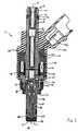
- FIG. 1illustrates a fuel injector assembly 10 , such as a high-pressure, direct-injection fuel injector assembly 10 .
- the fuel injector assembly 10has a housing, which includes a fuel inlet 12 , a fuel outlet 14 , and a fuel passageway 16 extending from the fuel inlet 12 to the fuel outlet 14 along a longitudinal axis 18 .
- the housingincludes an overmolded plastic member 20 cincturing a metallic support member 22 .
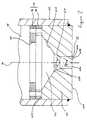
- the orifice portion 608has a first transverse cross-sectional area relative to the longitudinal axis 18 . That is to say, the first cross-sectional area can be measured in each of the imaginary planes that are oriented orthogonally to the longitudinal axis 18 as it extends through the orifice portion 608 , or it can be measured in each of the imaginary planes within the orifice portion 608 that are parallel to the downstream face 604 . It is most frequently the case that the downstream face 604 is oriented substantially orthogonal to the longitudinal axis 18 , and the longitudinal axis 18 consists of a straight line extending throughout the entire fuel injector assembly 10 . Consequently, the first cross-sectional area can be measured in each of the imaginary planes that are both oriented orthogonally to the longitudinal axis 18 and parallel to the downstream face 604 .
Landscapes
- Engineering & Computer Science (AREA)
- Chemical & Material Sciences (AREA)
- Combustion & Propulsion (AREA)
- Mechanical Engineering (AREA)
- General Engineering & Computer Science (AREA)
- Physics & Mathematics (AREA)
- Electromagnetism (AREA)
- Manufacturing & Machinery (AREA)
- Fuel-Injection Apparatus (AREA)
Abstract
Description
Claims (8)
Priority Applications (1)
| Application Number | Priority Date | Filing Date | Title |
|---|---|---|---|
| US09/559,749US6920690B1 (en) | 1999-04-27 | 2000-04-27 | Method of manufacturing a fuel injector seat |
Applications Claiming Priority (2)
| Application Number | Priority Date | Filing Date | Title |
|---|---|---|---|
| US13125199P | 1999-04-27 | 1999-04-27 | |
| US09/559,749US6920690B1 (en) | 1999-04-27 | 2000-04-27 | Method of manufacturing a fuel injector seat |
Publications (1)
| Publication Number | Publication Date |
|---|---|
| US6920690B1true US6920690B1 (en) | 2005-07-26 |
Family
ID=34752655
Family Applications (1)
| Application Number | Title | Priority Date | Filing Date |
|---|---|---|---|
| US09/559,749Expired - LifetimeUS6920690B1 (en) | 1999-04-27 | 2000-04-27 | Method of manufacturing a fuel injector seat |
Country Status (1)
| Country | Link |
|---|---|
| US (1) | US6920690B1 (en) |
Cited By (5)
| Publication number | Priority date | Publication date | Assignee | Title |
|---|---|---|---|---|
| EP1767774A1 (en)* | 2005-09-23 | 2007-03-28 | Siemens Aktiengesellschaft | Method and apparatus for manufacturing a valve group for an injector |
| US20110147636A1 (en)* | 2009-12-21 | 2011-06-23 | Denso Corporation | Constant residual pressure valve |
| US20160261064A1 (en)* | 2015-03-03 | 2016-09-08 | Teledyne Instruments, Inc. | Source energy connector pigtail |
| GB2561574A (en)* | 2017-04-18 | 2018-10-24 | Delphi Int Operations Luxembourg Sarl | Needle coating for injector closed loop |
| US20200271078A1 (en)* | 2015-12-29 | 2020-08-27 | Robert Bosch Gmbh | Fuel injector |
Citations (37)
| Publication number | Priority date | Publication date | Assignee | Title |
|---|---|---|---|---|
| US2273830A (en) | 1940-11-29 | 1942-02-24 | Ralph C Brierly | Method of making nozzle sprayer plates |
| US2534531A (en)* | 1945-11-08 | 1950-12-19 | Rossmanith Wolfgang | Machine for grinding internal cone surfaces |
| US2927737A (en) | 1952-04-12 | 1960-03-08 | Bosch Gmbh Robert | Fuel injection valves |
| US3430388A (en)* | 1965-02-11 | 1969-03-04 | Gilberta Gabrielli | Automatic or semi-automatic multi1 spindle grinder for diesel engine fuel nozzles |
| US3980237A (en)* | 1975-11-17 | 1976-09-14 | Allis-Chalmers Corporation | Differential valve in fuel injection nozzle |
| US4120456A (en) | 1976-01-28 | 1978-10-17 | Diesel Kiki Co., Ltd. | Fuel injection valve with vortex chamber occupying auxiliary valve |
| GB2029508A (en) | 1978-09-08 | 1980-03-19 | Bendix Corp | Fuel injector valve with contoured flow nozzle |
| DE2912814A1 (en)* | 1979-03-30 | 1980-10-09 | Gehring Gmbh Maschf | Finishing grinder for conical fuel injector seat - has tail sleeve holding and guiding workpiece in its bore, with grinding tool spindle extending through sleeve |
| GB2073954A (en) | 1978-11-17 | 1981-10-21 | Rech Soc Civ D Etudes | Electromagnetic injectors and methods for making same |
| DE3208536A1 (en)* | 1982-03-10 | 1983-09-15 | Maschinenfabrik Gehring Gmbh & Co Kg, 7302 Ostfildern | GRINDING DEVICE |
| GB2140626A (en) | 1983-04-25 | 1984-11-28 | Gerhard Mesenich | Electromagnetic actuator incorporating anti-chatter device |
| GB2151516A (en)* | 1983-11-30 | 1985-07-24 | Honda Motor Co Ltd | Manufacturing valve seat- forming member |
| US4643359A (en) | 1985-03-19 | 1987-02-17 | Allied Corporation | Mini injector valve |
| JPH0241973A (en) | 1988-07-30 | 1990-02-13 | Chigusa Sakudo Kk | Man truck for single-rail carriage car |
| US4984549A (en)* | 1984-03-05 | 1991-01-15 | Coltec Industries Inc. | Electromagnetic injection valve |
| US5114077A (en) | 1990-12-12 | 1992-05-19 | Siemens Automotive L.P. | Fuel injector end cap |
| JPH04232378A (en)* | 1990-12-28 | 1992-08-20 | Japan Electron Control Syst Co Ltd | Method for forming injection port of fuel injection valve |
| US5207384A (en) | 1991-09-18 | 1993-05-04 | Siemens Automotive L.P. | Swirl generator for an injector |
| US5241938A (en) | 1990-03-14 | 1993-09-07 | Aisan Kogyo Kabushiki Kaisha | Injector with assist air passage for atomizing fuel |
| US5271563A (en) | 1992-12-18 | 1993-12-21 | Chrysler Corporation | Fuel injector with a narrow annular space fuel chamber |
| DE4222137A1 (en) | 1992-07-06 | 1994-01-13 | Bosch Gmbh Robert | Fuel injection nozzle for diesel engines - with fine hole-jets in nozzle body reduced in size near outlet by convergent deposit of hard metal or ceramic |
| US5409169A (en) | 1991-06-19 | 1995-04-25 | Hitachi America, Ltd. | Air-assist fuel injection system |
| US5462231A (en) | 1994-08-18 | 1995-10-31 | Siemens Automotive L.P. | Coil for small diameter welded fuel injector |
| US5494224A (en) | 1994-08-18 | 1996-02-27 | Siemens Automotive L.P. | Flow area armature for fuel injector |
| US5601476A (en)* | 1993-12-15 | 1997-02-11 | Kadia-Maschinenbau Kopp Gmbh & Co. | Method for precision-grinding a bezel at the inlet bore a workpiece |
| US5625946A (en) | 1995-05-19 | 1997-05-06 | Siemens Automotive Corporation | Armature guide for an electromechanical fuel injector and method of assembly |
| US5630400A (en) | 1995-10-17 | 1997-05-20 | Mitsubishi Denki Kabushiki Kaisha | Fuel injection valve for an internal combustion engine |
| US5636796A (en) | 1994-03-03 | 1997-06-10 | Nippondenso Co., Ltd. | Fluid injection nozzle |
| JPH10128647A (en)* | 1996-10-29 | 1998-05-19 | Toyo A Tec Kk | Deburring method and deburring structure of grinding wheel used in the deburring method |
| US5871157A (en) | 1996-07-29 | 1999-02-16 | Mitsubishi Denki Kabushiki Kaisha | Fuel injection valve |
| US5875972A (en) | 1997-02-06 | 1999-03-02 | Siemens Automotive Corporation | Swirl generator in a fuel injector |
| WO1999010649A1 (en) | 1997-08-22 | 1999-03-04 | Robert Bosch Gmbh | Fuel injection valve |
| WO1999010648A1 (en) | 1997-08-22 | 1999-03-04 | Robert Bosch Gmbh | Fuel injection valve |
| FR2772432A1 (en) | 1997-12-12 | 1999-06-18 | Magneti Marelli France | PETROL INJECTOR WITH ANTI-CALAMINE COATING, FOR DIRECT INJECTION |
| DE19907859A1 (en) | 1998-08-27 | 2000-03-02 | Bosch Gmbh Robert | Fuel injection valve for direct injection into combustion chamber of internal combustion engine has activatable operating component with valve closure body movable axially along valve longitudinal axis |
| US6173494B1 (en)* | 1998-05-06 | 2001-01-16 | Ernst Thielenhaus Kg | Method of making a valve seat |
| US6189816B1 (en)* | 1997-12-20 | 2001-02-20 | Robert Bosch Gmbh | Method for producing a valve-seat body for a fuel injection valve, and corresponding fuel injection valve |
- 2000
- 2000-04-27USUS09/559,749patent/US6920690B1/ennot_activeExpired - Lifetime
Patent Citations (39)
| Publication number | Priority date | Publication date | Assignee | Title |
|---|---|---|---|---|
| US2273830A (en) | 1940-11-29 | 1942-02-24 | Ralph C Brierly | Method of making nozzle sprayer plates |
| US2534531A (en)* | 1945-11-08 | 1950-12-19 | Rossmanith Wolfgang | Machine for grinding internal cone surfaces |
| US2927737A (en) | 1952-04-12 | 1960-03-08 | Bosch Gmbh Robert | Fuel injection valves |
| US3430388A (en)* | 1965-02-11 | 1969-03-04 | Gilberta Gabrielli | Automatic or semi-automatic multi1 spindle grinder for diesel engine fuel nozzles |
| US3980237A (en)* | 1975-11-17 | 1976-09-14 | Allis-Chalmers Corporation | Differential valve in fuel injection nozzle |
| US4120456A (en) | 1976-01-28 | 1978-10-17 | Diesel Kiki Co., Ltd. | Fuel injection valve with vortex chamber occupying auxiliary valve |
| GB2029508A (en) | 1978-09-08 | 1980-03-19 | Bendix Corp | Fuel injector valve with contoured flow nozzle |
| GB2073954A (en) | 1978-11-17 | 1981-10-21 | Rech Soc Civ D Etudes | Electromagnetic injectors and methods for making same |
| DE2912814A1 (en)* | 1979-03-30 | 1980-10-09 | Gehring Gmbh Maschf | Finishing grinder for conical fuel injector seat - has tail sleeve holding and guiding workpiece in its bore, with grinding tool spindle extending through sleeve |
| US4545152A (en)* | 1982-03-10 | 1985-10-08 | Maschinenfabrik Gehring, Gmbh & Co. Kommanditgesellschaft | Grinding apparatus |
| DE3208536A1 (en)* | 1982-03-10 | 1983-09-15 | Maschinenfabrik Gehring Gmbh & Co Kg, 7302 Ostfildern | GRINDING DEVICE |
| GB2140626A (en) | 1983-04-25 | 1984-11-28 | Gerhard Mesenich | Electromagnetic actuator incorporating anti-chatter device |
| GB2151516A (en)* | 1983-11-30 | 1985-07-24 | Honda Motor Co Ltd | Manufacturing valve seat- forming member |
| US4984549A (en)* | 1984-03-05 | 1991-01-15 | Coltec Industries Inc. | Electromagnetic injection valve |
| US4643359A (en) | 1985-03-19 | 1987-02-17 | Allied Corporation | Mini injector valve |
| JPH0241973A (en) | 1988-07-30 | 1990-02-13 | Chigusa Sakudo Kk | Man truck for single-rail carriage car |
| US5241938A (en) | 1990-03-14 | 1993-09-07 | Aisan Kogyo Kabushiki Kaisha | Injector with assist air passage for atomizing fuel |
| US5114077A (en) | 1990-12-12 | 1992-05-19 | Siemens Automotive L.P. | Fuel injector end cap |
| JPH04232378A (en)* | 1990-12-28 | 1992-08-20 | Japan Electron Control Syst Co Ltd | Method for forming injection port of fuel injection valve |
| US5409169A (en) | 1991-06-19 | 1995-04-25 | Hitachi America, Ltd. | Air-assist fuel injection system |
| US5207384A (en) | 1991-09-18 | 1993-05-04 | Siemens Automotive L.P. | Swirl generator for an injector |
| DE4222137A1 (en) | 1992-07-06 | 1994-01-13 | Bosch Gmbh Robert | Fuel injection nozzle for diesel engines - with fine hole-jets in nozzle body reduced in size near outlet by convergent deposit of hard metal or ceramic |
| US5271563A (en) | 1992-12-18 | 1993-12-21 | Chrysler Corporation | Fuel injector with a narrow annular space fuel chamber |
| US5601476A (en)* | 1993-12-15 | 1997-02-11 | Kadia-Maschinenbau Kopp Gmbh & Co. | Method for precision-grinding a bezel at the inlet bore a workpiece |
| US5636796A (en) | 1994-03-03 | 1997-06-10 | Nippondenso Co., Ltd. | Fluid injection nozzle |
| US5462231A (en) | 1994-08-18 | 1995-10-31 | Siemens Automotive L.P. | Coil for small diameter welded fuel injector |
| US5494224A (en) | 1994-08-18 | 1996-02-27 | Siemens Automotive L.P. | Flow area armature for fuel injector |
| US5625946A (en) | 1995-05-19 | 1997-05-06 | Siemens Automotive Corporation | Armature guide for an electromechanical fuel injector and method of assembly |
| US5630400A (en) | 1995-10-17 | 1997-05-20 | Mitsubishi Denki Kabushiki Kaisha | Fuel injection valve for an internal combustion engine |
| US5871157A (en) | 1996-07-29 | 1999-02-16 | Mitsubishi Denki Kabushiki Kaisha | Fuel injection valve |
| JPH10128647A (en)* | 1996-10-29 | 1998-05-19 | Toyo A Tec Kk | Deburring method and deburring structure of grinding wheel used in the deburring method |
| US5875972A (en) | 1997-02-06 | 1999-03-02 | Siemens Automotive Corporation | Swirl generator in a fuel injector |
| WO1999010649A1 (en) | 1997-08-22 | 1999-03-04 | Robert Bosch Gmbh | Fuel injection valve |
| WO1999010648A1 (en) | 1997-08-22 | 1999-03-04 | Robert Bosch Gmbh | Fuel injection valve |
| FR2772432A1 (en) | 1997-12-12 | 1999-06-18 | Magneti Marelli France | PETROL INJECTOR WITH ANTI-CALAMINE COATING, FOR DIRECT INJECTION |
| WO1999031382A1 (en) | 1997-12-12 | 1999-06-24 | Magneti Marelli France | Fuel injector with anti-scale ceramic coating for direct injection |
| US6189816B1 (en)* | 1997-12-20 | 2001-02-20 | Robert Bosch Gmbh | Method for producing a valve-seat body for a fuel injection valve, and corresponding fuel injection valve |
| US6173494B1 (en)* | 1998-05-06 | 2001-01-16 | Ernst Thielenhaus Kg | Method of making a valve seat |
| DE19907859A1 (en) | 1998-08-27 | 2000-03-02 | Bosch Gmbh Robert | Fuel injection valve for direct injection into combustion chamber of internal combustion engine has activatable operating component with valve closure body movable axially along valve longitudinal axis |
Non-Patent Citations (5)
| Title |
|---|
| English Translation of 60-019957 (YUJI).* |
| Geometrical Effects on Flow Characteristics of Gasoline High Pressure Direct Injecter, W.M. Ren, J. Shen, J.F. Nally Jr., p. 1-7, (97FL-95). |
| Patent Abstracts of Japan JP 59-180062 (Oct. 12, 1984); Isuzu Motors, Ltd. |
| Patent Abstracts of Japan JP 60-019957 (Feb. 1, 1985); Japan Electronic Control Syst. Co. Ltd. |
| Roberson, J. A. & Crowne, C.T. "Engineering Fluid Mechanics." 6th ed. 1997. p. 531-534.* |
Cited By (7)
| Publication number | Priority date | Publication date | Assignee | Title |
|---|---|---|---|---|
| EP1767774A1 (en)* | 2005-09-23 | 2007-03-28 | Siemens Aktiengesellschaft | Method and apparatus for manufacturing a valve group for an injector |
| US20110147636A1 (en)* | 2009-12-21 | 2011-06-23 | Denso Corporation | Constant residual pressure valve |
| US20160261064A1 (en)* | 2015-03-03 | 2016-09-08 | Teledyne Instruments, Inc. | Source energy connector pigtail |
| US9761994B2 (en)* | 2015-03-03 | 2017-09-12 | Teledyne Instruments, Inc. | Source energy connector pigtail |
| US20200271078A1 (en)* | 2015-12-29 | 2020-08-27 | Robert Bosch Gmbh | Fuel injector |
| GB2561574A (en)* | 2017-04-18 | 2018-10-24 | Delphi Int Operations Luxembourg Sarl | Needle coating for injector closed loop |
| GB2561574B (en)* | 2017-04-18 | 2020-09-23 | Delphi Tech Ip Ltd | Needle coating for injector closed loop |
Similar Documents
| Publication | Publication Date | Title |
|---|---|---|
| US6334434B1 (en) | Fuel injector seat with a sharp edge | |
| US4890794A (en) | Perforated body for a fuel injection valve | |
| US5016821A (en) | Fuel injection valve | |
| US4951372A (en) | Method for adjusting injection ports in a fuel injection valve | |
| EP1111231A2 (en) | A fuel injector having an integrated seat and swirl generator | |
| JPH0530987B2 (en) | ||
| JPH0534515B2 (en) | ||
| US20080006713A1 (en) | Fuel injector having an internally mounted cross-flow nozzle for enhanced compressed natural gas jet spray | |
| JP4435161B2 (en) | Orifice disk for fuel injector and method of forming the same | |
| CN1058070C (en) | Fuel spraying valve | |
| US6920690B1 (en) | Method of manufacturing a fuel injector seat | |
| KR940011344B1 (en) | Fuel injection valve | |
| GB2198476A (en) | Fuel injection valve | |
| US6820826B2 (en) | Spray targeting to an arcuate sector with non-angled orifices in fuel injection metering disc and method | |
| JP2003184706A (en) | Fuel injection valve | |
| JP3726830B2 (en) | Fuel injection nozzle and fuel supply device | |
| JP3336697B2 (en) | Swirl nozzle in fuel injection valve | |
| US7108201B2 (en) | Injection valve | |
| US6047473A (en) | Inlet port flat wall section |
Legal Events
| Date | Code | Title | Description |
|---|---|---|---|
| AS | Assignment | Owner name:SIEMENS AUTOMOTIVE CORPORATION, MICHIGAN Free format text:ASSIGNMENT OF ASSIGNORS INTEREST;ASSIGNOR:IMOEHL, WILLIAM JAMES;REEL/FRAME:011653/0418 Effective date:20000929 | |
| AS | Assignment | Owner name:SIEMENS VDO AUTOMOTIVE CORP., MICHIGAN Free format text:ASSIGNMENT OF ASSIGNORS INTEREST;ASSIGNOR:SIEMENS AUTOMOTIVE CORP.;REEL/FRAME:015451/0652 Effective date:20020101 | |
| STCF | Information on status: patent grant | Free format text:PATENTED CASE | |
| AS | Assignment | Owner name:TECHLAND RESEARCH, INC., OHIO Free format text:ASSIGNMENT OF ASSIGNORS INTEREST;ASSIGNORS:SANDERS, BOBBY W.;SANDERS, CHARLOTTE A.;WEIR, LOIS J.;REEL/FRAME:017006/0988;SIGNING DATES FROM 20050811 TO 20050827 | |
| FEPP | Fee payment procedure | Free format text:PAYER NUMBER DE-ASSIGNED (ORIGINAL EVENT CODE: RMPN); ENTITY STATUS OF PATENT OWNER: LARGE ENTITY Free format text:PAYOR NUMBER ASSIGNED (ORIGINAL EVENT CODE: ASPN); ENTITY STATUS OF PATENT OWNER: LARGE ENTITY | |
| FPAY | Fee payment | Year of fee payment:4 | |
| FPAY | Fee payment | Year of fee payment:8 | |
| AS | Assignment | Owner name:CONTINENTAL AUTOMOTIVE SYSTEMS US, INC., MICHIGAN Free format text:CHANGE OF NAME;ASSIGNOR:SIEMENS VDO AUTOMOTIVE CORPORATION;REEL/FRAME:035197/0309 Effective date:20071203 | |
| AS | Assignment | Owner name:CONTINENTAL AUTOMOTIVE SYSTEMS, INC., MICHIGAN Free format text:MERGER;ASSIGNOR:CONTINENTAL AUTOMOTIVE SYSTEMS US, INC.;REEL/FRAME:035217/0258 Effective date:20121212 | |
| FPAY | Fee payment | Year of fee payment:12 |