US6920493B1 - System and method for communicating coalesced rule parameters in a distributed computing environment - Google Patents
System and method for communicating coalesced rule parameters in a distributed computing environmentDownload PDFInfo
- Publication number
- US6920493B1 US6920493B1US09/812,841US81284101AUS6920493B1US 6920493 B1US6920493 B1US 6920493B1US 81284101 AUS81284101 AUS 81284101AUS 6920493 B1US6920493 B1US 6920493B1
- Authority
- US
- United States
- Prior art keywords
- tree
- packet
- rule parameters
- validation
- concast
- Prior art date
- Legal status (The legal status is an assumption and is not a legal conclusion. Google has not performed a legal analysis and makes no representation as to the accuracy of the status listed.)
- Expired - Lifetime, expires
Links
Images


Classifications
- H—ELECTRICITY
- H04—ELECTRIC COMMUNICATION TECHNIQUE
- H04L—TRANSMISSION OF DIGITAL INFORMATION, e.g. TELEGRAPHIC COMMUNICATION
- H04L63/00—Network architectures or network communication protocols for network security
- H04L63/10—Network architectures or network communication protocols for network security for controlling access to devices or network resources
- H04L63/104—Grouping of entities
- H—ELECTRICITY
- H04—ELECTRIC COMMUNICATION TECHNIQUE
- H04L—TRANSMISSION OF DIGITAL INFORMATION, e.g. TELEGRAPHIC COMMUNICATION
- H04L63/00—Network architectures or network communication protocols for network security
- H04L63/14—Network architectures or network communication protocols for network security for detecting or protecting against malicious traffic
- H04L63/1441—Countermeasures against malicious traffic
- H04L63/1458—Denial of Service
Definitions
- the present inventionrelates in general to packet validation device communication and, in particular, to a system and method for communicating coalesced rule parameters in a distributed computing environment.
- Intranetworksinclude individual computers and shared resources interconnected within a shared common network domain.
- Internetworksconsist of interconnected intranetworks and geographically distributed computational resources which, when taken as a whole, comprise a unified set of loosely associated computers.
- Each separate component within an internetworkhas a unique address.
- the Internetfor example, is a public internetwork interconnecting computers worldwide.
- TCP/IPTransmission Control Protocol/Internet Protocol
- TCPTransmission Control Protocol
- TCP-based networksare also particularly susceptible to denial of service (“DoS”) attacks.
- DoSdenial of service
- TCP serversreserve state, such as memory buffers and ports, upon receiving a service request from a client during a communication session initiation.
- a state consumption DoS attackattempts to force a victim server to needlessly allocate and waste resources used to hold per-connection state information.
- the attackersends a high volume of bogus service requests to the victim server, which continues to allocate resources for per-connection state until all available resources are utilized. No additional state is left to be allocated for valid requesters and service is denied.
- a distributed DoS (DDoS) attackoccurs when the attacker engages compromised hosts to participate in the attack by also sending bogus service requests.
- DoS attacksare difficult to detect because the bogus service requests are indistinguishable from normal network traffic.
- One form of DoS attackemploys “spoofed” packet source addresses. TCP alone does not provide means for ensuring that packet source addresses are valid. Rather, upper layer protocols must be used in conjunction with TCP to guarantee that a packet originated from the host located at the source address specified in the packet header. Attackers take advantage of this security hole by sending bogus service request packets using fraudulent source addresses to disguise their identity. The fraudulent source addresses could be the address of another system or might be a source address that is valid yet not presently in use.
- intermediary-based packet validation deviceshave been employed to counter spoofed DoS attacks. These devices include conventional firewalls and proxy firewalls which are situated between a protected network domain or servers and potential attackers. In one form, these devices filter packets by applying validation rules. The source addresses of incoming packets are compared to parameterized lists of individual addresses for “bad” hosts.
- a “bad” hostis a server which either originated a bogus service request or caused a bogus service request to be sent using a fraudulent source address.
- Packet validation devicesare typically deployed in two configurations.
- a parallel configurationa plurality of devices commonly protect a shared network enclave or server farm having a shared network domain.
- a parallel configurationcould be found in, for instance, a multi-pathed server environment.
- a serial configurationoccurs where packet validation devices are deployed at various network points, including within an intranetwork and throughout an internetwork. Serial devices do not share common network domains.
- Both parallel- and serially-configured packet validation devicesoperate independently of each other. No communication channel interfacing the various devices exists. Consequently, while any given device may independently detect and respond to a DoS attack, the knowledge of the attack, in particular, the parameters identifying the bad host address, are not shared with other devices.
- each deviceimplements a finite amount of table space in which to list bad hosts.
- the table spacecan become saturated and the reallocation of additional space can cause delays.
- propagation delayscan occur through the serialization of sequential devices where each device checks and rechecks packet traffic against their own individual parametized lists of bad hosts.
- traffic originating from that same validated hostmust either undergo re-validation with the peer devices or risk being dropped as un-validated traffic.
- a concast treeincludes a plurality of hierarchically structured tree nodes through which packet validation rule parameters are received, consolidated and forwarded to a next-higher layer.
- Individual packet validation devicesapply parameterized validation rules to validate transiting network traffic.
- the rule parametersare forwarded into a lowest layer of the concast tree.
- Duplicate rule parameters and those parameters sharing a common network Domain Name System (DNS) domain space or Internet Protocol (IP) subnetare consolidated and forwarded to the next higher layer in the concast tree.
- a control centerreceives the aggregate rule parameters and disseminates the parameters back to the individual packet validation devices for application.
- DNSDomain Name System
- IPInternet Protocol
- An embodiment of the present inventionis a system and a method for dynamically configuring parameterized validation rules in a distributed computing environment.
- a plurality of packet validation devicesis each situated within the distributed computing environment at packet routing points. Each packet validation device validates packet traffic using parameterized validation rules.
- a plurality of hierarchical tree nodesare structured into a plurality of tiered layers with each tree node interfaced to at least one other tree node. Those tree nodes at a lowermost layer are further interfaced to at least one packet validation device from which validation rule parameters are retrieved and processed.
- a root tree nodeis interfaced to an uppermost layer of tree nodes from which validation rule parameters, retrieved from the root tree node, are disseminated to each of the packet validation devices.
- a further embodimentis a system and a method for communicating coalesced rule parameters in a distributed computing environment.
- a plurality of packet validation devicesis communicatively interposed between network routing points within the distributed computing environment. The packet validation devices apply parameterized rules to transiting network packet traffic.
- a plurality of processing tree nodesis configured into a concast tree. In a lowermost layer of the concast tree, each processing tree node collects and coalesces rule parameters from at least one packet validation device. In each successive layer of the concast tree, each processing tree node collects and coalesce the rule parameters from at least one processing tree node in a next lower layer of the concast tree.
- a control centerassembles the coalesced rule parameters from each packet validation device in an uppermost layer of the concast tree. The coalesced rule parameters are forwarded from the control center to each packet validation device along a dissemination path.
- FIG. 1is a functional block diagram showing a distributed computing environment, including a system for communicating coalesced rule parameters, in accordance with the present invention.
- FIG. 2is a network diagram illustrating, by way of example, the progression of a distributed denial of service attack.
- FIG. 3is a block diagram showing the system for communicating coalesced rule parameters of FIG. 1 .
- FIG. 4is a tree diagram showing, by way of example, the removal of duplicate rule parameters.
- FIG. 5is a tree diagram showing, by way of example, the coalescing of network address space.
- FIG. 6is a block diagram showing, by way of example, the application of a vicinity affinity filter.
- FIG. 7is a flow diagram showing a method for communicating coalesced rule parameters for an individual packet validation device in accordance with the present invention.
- FIG. 8is a flow diagram showing a method for communicating coalesced rule parameters for a node in a concast tree in accordance with the present invention.
- FIG. 9is a flow diagram showing a method for communicating coalesced rule parameters for a control center in accordance with the present invention.
- FIG. 1is a functional block diagram showing a distributed computing environment 10 , including a system for communicating coalesced rule parameters, in accordance with the present invention.
- a host server 11operates within an internet protocol (IP) based network subdomain 12 .
- the host server 11is interconnected to the internetwork 14 through the network subdomain 12 via a router 13 .
- a plurality of remote serversincluding server A 15 , server B 18 , and server C 21 , each operate in their respective network subdomains 16 , 19 , 22 and are interconnected to the internetwork 14 via a router 17 , 20 , 23 .
- Each individual network subdomain 12 , 16 , 19 , 22includes a packet validation device (not shown) incorporated within each of the respective routers 13 , 17 , 20 , 23 .
- the packet validation devicesapply parameterized validation rules to packet traffic flowing into and out of their respective network subdomains 12 , 16 , 19 , 22 .
- “Negative” validation rulesdisallow the forwarding of packets originating from “bad” hosts, that is, hosts within the network that have either been previously identified as passing invalid traffic, such as a bogus service request, or fraudulently addressed packets
- “positive” validation rulesonly allow the forwarding of packets originating from specifically authorized or validated” “good” hosts.
- the packet validation devicescan apply either negative or positive validation rules.
- the parameters storing the identified “bad” hosts (negative parameters) or “good” hosts (positive parameters)are forwarded to tree nodes 24 interfaced to each of the routers 13 , 17 , 20 , 23 .
- the tree nodes 24constitute a lowermost layer of a hierarchically structured concast tree.
- the concast treeconcentrates the transferal and exchange of validation rule parameters for communication between each of the other packet validation devices.
- the validation rule parametersare passed from the individual routers 13 , 17 , 20 , 23 to the tree nodes 24 in the lowermost layer of the concast tree.
- the parametersare subsequently forwarded to tree nodes 25 in one or more intermediate layers of the concast tree and finally to a tree node 26 in the uppermost layer.
- the forwarded validation rule parametersare received by a centralized control center (CC) 27 which disseminates the parameters back down to the individual packet validation devices.
- CCcentralized control center
- the rulesare coalesced into increasingly refined values which remove duplicate and commonly shared address space parameters based on the global knowledge received from other packet validation devices.
- each of the packet validation devicesapplies a vicinity affinity filter to the coalesced packet validation parameters to limit the scope of the parameterized validation rules in use at any given time to the fewest required rules.
- the individual computer systemsincluding servers 11 , 15 , 18 , 21 , are general purpose, programmed digital computing devices consisting of a central processing unit (CPU), random access memory (RAM), non-volatile secondary storage, such as a hard drive or CD ROM drive, network interfaces, and peripheral devices, including user interfacing means, such as a keyboard and display.
- Program codeincluding software programs, and data are loaded into the RAM for execution and processing by the CPU and results are generated for display, output, transmittal, or storage.
- FIG. 2is a network diagram 30 illustrating, by way of example, the progression of a spoofed denial of service (DoS) attack.
- DoSdenial of service
- the goal of the spoofed DoS attackis to induce a victim server T 32 into allocating state, such as memory buffers, ports and similar limited resources, through incomplete bogus service requests.
- Spoofed DoS attacksusually occur in TCP/IP compliant environments, particularly with connection-oriented protocols, such as TCP.
- Spoofed DoS attacksrefer to the generic category of DoS attacks in which the source address of packets used in an attack are forged with either an address of another server or with an unused yet valid network address. This type of attack relies upon the inherent trust placed in network traffic.
- a flooding attackis a specific form of DoS attack that attempts to saturate scarce network resources by either causing traffic congestion or resource consumption. Generally, the packets used in effecting a flooding attack are spoofed.
- an attacker 31selects a target 32 interconnected via an internetwork 33 .
- the target 32will be situated on a remote intranetwork 34 with the attacker 31 and remote intranetwork 34 interconnected to the internetwork 33 using routers 35 or similar connectivity devices.
- the attacker 31will send a large volume of packets 36 and attempt to cause a sufficiently high volume of packet traffic along the path leading to the target 32 (step ⁇ circle around (1) ⁇ ).
- the link to the target 32will become congested and saturated with traffic or the target 32 will exhaust substantially all available resources, at which point a denial of service is achieved.
- the attacker 31could enlist the assistance of compromised or “stooged” hosts 37 a , 37 b , 37 c in a multi-source flooding attack.
- the compromised hosts 37 a , 37 b , 37 care interconnected via an intranetwork 39 in turn interconnected to the internetwork 33 via a router 38 or similar connectivity device.
- the attacker 31coordinates the transmittal of spoofed packets 40 a , 40 b , 40 c from the compromised hosts 37 a , 37 b , 37 c which collectively converge on the target 32 (step ⁇ circle around (2) ⁇ ).
- the link to the target 32eventually becomes congested and saturated with spoofed packet traffic, or the target 32 allocates substantially all available state, thereby achieving a denial of service.
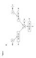
- FIG. 3is a block diagram showing the system for communicating coalesced rule parameters 50 of FIG. 1 .
- the system 50includes three primary groups of components: packet validation devices 59 - 62 , a concast tree 63 , and a control center (CC) 67 . These components cooperatively exchange rule parameters on a continuing basis, as further described below beginning with reference to FIG. 7 .
- Each componentis a computer program, procedure or module written as source code in a conventional programming language, such as the C++ programming language, and is presented for execution by the CPU as object or byte code, as is known in the art.
- the various implementations of the source code and object and byte codescan be held on a computer-readable storage medium or embodied on a transmission medium in a carrier wave.
- the componentsoperate in accordance with a sequence of process steps, as further described below beginning with reference to FIG. 7 .
- a plurality of network subdomains IP H 51 , IP X 52 , IP Y 53are interconnected via an intranetwork 54 .
- Each of the network subdomains IP H 51 , IP X 52 , IP Y 53are either individual servers or hosts or intranetworks connecting multiple servers, hosts and clients, or some combination thereof
- each of the network subdomains IP H 51 , IP X 52 , IP Y 53are interconnected to the internetwork 54 via a router 55 or similar connectivity device (shown only for subdomain IP H 51 ).
- the internetwork 54includes multiple routers 56 , 57 , 58 for internally routing packet traffic.
- the internetwork 54is an IP-compliant network and packet traffic is internally routed using the border gateway protocol or similar form of dynamic routing protocol, such as described in W. R. Stephens, “TCP/IP Illustrated, Vol. 1,” Ch. 10, Addison Wesley Publishing Co. (1994), the disclosure of which is incorporated by reference.
- the individual routers 55 - 58are paired with a packet validation device 59 - 62 .
- each of the routers 55 - 58could implement the packet validation rule sets as part of their functionality.
- Each of the packet validation devices 59 - 62applies parameterized packet validation rules to packet traffic transiting through the associated router 55 - 58 .
- each packet validation device 59 - 62is situated at a packet routing point within the internetwork 54 .
- the parameterized packet validation ruleseither exclude those packets originating from either a known attacker or a network address that has not been validated (negative validation rules) or include only those packets originating from a validated host (positive validation rules).
- the packet validation devices 59 - 62operate independently of each other, , H but communicate to an associated node 68 a-d in a lowermost layer 64 of the concast tree 63 . Upon the non-validation of a packet, the rule parameters are forwarded to the associated node 68 a-d.
- the concast tree 63can have an arbitrary number of layers. However, those nodes 68 a-d in the lowermost layer 64 of the concast tree 63 function as the origination point of coalesced rule parameters received from packet validation devices 59 - 62 . The received rule parameters are collected and coalesced by the interior node 69 a-b in the intermediate layers 65 of the concast tree 63 . The interior nodes 69 a-b remove duplicate rule parameters and consolidate commonly-identified network address space to successively refine the sets of rule parameters traveling upwards in the concast tree 63 .
- the concast tree 63includes a root node 70 in an uppermost layer 66 .
- the root node 70collects all of the forwarded rule parameters into a single centralized point.
- the root node 70periodically forwards the consolidated rule parameters to a control center (CC) 67 , possibly incorporated into part of the concast tree 63 .
- the control center 67disseminates the rule parameters to the individual packet validation devices 59 - 62 .
- the communication of the rule parameters upwards through the concast tree 63 and downwards to the packet validation devices 59 - 62is logically separable.
- the concast tree 63is a hierarchical structure requiring the rule parameters to travel from the lowermost layer 64 to the uppermost layer 66 via the interior layers 65 .
- the interior nodes 69 a-bcoalesce the forwarded rule parameters, as further described below with reference to FIGS. 4 and 5 .
- the dissemination of coalesced rule parameters from the control center 67 to the packet validation devices 59 - 62need not travel along the same path and can occur directly between the control center 67 and each device.
- the communication to, from and between the nodes comprising the concast tree 63can occur via in-band or out-of-band communications, or via some combination thereof
- An in-band communications channelcould be formed, by way of example, by reserving bandwidth within the internetwork 54 for communicating between the various nodes.
- An out-of-band communications channelcould be formed using interconnections peripheral to the internetwork 54 .
- the dissemination of rule parameters from the control center 67 to the packet validation devices 59 - 62could also occur via in-band or out-of-band communications, including via a Global Satellite Broadcast channel, or via some combination thereof.
- FIG. 4is a tree diagram showing, by way of example, the removal of duplicate rule parameters.
- a set of peer nodes 83 a , 83 b in an intermediate layer 81 of a concast tree 80both forward a set of rule parameters 84 , 85 containing a network address of 190.165.1.100.
- Each of these address sets 84 , 85have been respectively received from different packet validation devices 59 - 62 (shown in FIG. 3 ). However, by implication, the source address 190.165.1.100 is from a “bad” host that was non-validated by at least the two packet validation devices 59 - 62 .
- a parent node 86 in the next higher layer 82 of the concast tree 80removes the duplicate rule parameters and forwards a single rule parameter 87 containing the identified network address 190.165.1.100.
- FIG. 5is a tree diagram showing, by way of example, the coalescing of rule parameters.
- a set of peer nodes 93 a , 93 b in intermediate layer 91 of a concast tree 90forward a set of rule parameters 94 , 95 respectively containing the network addresses 190.165.1.63 and 190.165.1.101.
- these rule parametersindicate that at least two of the packet validation devices 59 - 62 have non-validated packets received from separate “bad” hosts having a “source” address of 190.165.1.63 and 190.165.1.101.
- rule parameters 94 , 95are coalesced upon the occurrence of at least four separately-identified network address spaces, although as few as two can suffice in some network environments.
- two aggregation heuristicscan be applied to the rule parameters to determine a commonly identified network address space.
- expansive aggregationapplies a netmask that covers the largest possible network address space. For example, a netmask of 255.255.255.240 is the most expansive unifier. Applying this netmask to rule parameter 94 would result in a network address space of 190.165.1.48 and to rule parameter 95 would result in a network address space of 190.165.1.96.
- negative aggregationapplies a netmask that most limits the network address space.
- a netmask of 255.255.255.160is aggregate of 190.165.1.48 ⁇ 190.165.1.96 and is therefore the most restrictive unifier. Applying this netmask to rule parameter 94 or to rule parameter 95 in both cases would result in a network address space of 190.165.1.32.
- Other aggregation heuristicsare possible, as would be recognized by one skilled in the art.
- FIG. 6is a block diagram showing, by way of example, the application of a vicinity affinity filter 100 .
- the vicinity affinity filter 100is applied by each individual packet validation device 59 - 62 (shown in FIG. 3 ) to limit the application of the coalesced rule parameters 104 received from the control center 67 (shown in FIG. 3 ).
- certain packet validation devices 59 - 62validate network traffic from a limited address space within the internetwork 54 .
- a packet validation device 101 operating in conjunction with a router 102 in support of a network subdomain 103 having a network address space of 190.165.1.XXXneed not consider rule parameters falling outside of that domain for outgoing packets.
- a rule parameter 105 specifying a domain address of 190.165.1.1would be extracted from a set of coalesced rule parameters 104 into an abbreviated rule parameter set 106 containing just the rule parameter 105 for the network address 190.165.1.1.
- the vicinity affinity filter 100is applied for those network domains 103 falling within three “hops” of the packet validation device 101 , although link paths having other lengths are also feasible.
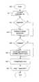
- FIG. 7is a flow diagram showing a method 120 for communicating coalesced rule parameters for an individual packet validation device 59 - 62 in accordance with the present invention.
- the purpose of the method 120is to forward rule parameters from the packet validation device 59 - 62 (shown in FIG. 3 ) to the nodes 68 a-b in the lower-most layer 64 of the concast tree 63 .
- the actual validation of packetsis omitted from discussion and outside the subject matter of the present invention.
- An approach to validating packets using negative packet validation rulesis described in D. X. Song et al., “Advanced and Authenticated Marking Schemes for IP Traceback,” Tech. Rep. No. UCB/CSD-00-1107, Univ. of Cal. (June 2000), the disclosure of which is incorporated by reference.
- Transiting network packetsare processed in an iterative loop (blocks 121 - 127 ) as follows. First, if the packet contains rule parameters (block 123 ) and, by application of the vicinity affinity filter 100 (shown in FIG. 6 ), the parameters are within the network domain of the packet validation device (block 123 ), the rule parameters are saved and applied to future packets transiting the packet validation device (block 124 ). Otherwise, if the packet does not contain a set of rule parameters (block 122 ), the packet is validated (block 125 ).
- the rule parameteris sent (block 127 ) to the associated node 68 a-d in the lowermost layer 64 of the concast tree 63 . Processing continues for each subsequent packet (block 128 ), after which processing terminates.
- FIG. 8is a flow diagram showing a method 140 for communicating coalesced rule parameters for a node in a concast tree in accordance with the present invention.
- the purpose of the method 140is to process rule parameters received from either a packet validation device 59 - 62 (shown in FIG. 3 ) or a child node from the next lower layer in the concast tree 63 .
- Rule parametersare processed in an iterative loop (block 141 - 147 ) as follows. First, if the rule parameters are duplicated (block 142 ), the duplicate rule parameters are removed (block 143 ) and only a unique occurrence is forwarded to the next layer in the concast tree 63 .
- the rule parametersare coalesced (block 144 ) to consolidate any commonly identified address spaces (block 145 ) shared by two or more of the rule parameters.
- the consolidated rule parameteris forwarded to the next higher layer in the concast tree 63 or, if the node is the root node 70 , to the control center 67 (block 146 ). Processing of each successive rule parameter set continues (block 147 ) until all sets have been processed, after which the routine terminates.
- FIG. 9is a flow diagram showing a method 160 for communicating coalesced rule parameters for a control center in accordance with the present invention.
- the purpose of the method 160is to forward consolidated rule parameters to the individual packet validation devices 59 - 62 (shown in FIG. 3 ).
- the dissemination of the rule parametersis performed in an iterative loop (blocks 161 - 163 ) during each iteration of which the consolidated packet validation rules are disseminated to the individual packet validation devices 59 - 62 (block 162 ). Iterative processing continues for each of the rule parameters (block 163 ), after which the routine terminates.
Landscapes
- Engineering & Computer Science (AREA)
- Computer Security & Cryptography (AREA)
- Computer Hardware Design (AREA)
- Computing Systems (AREA)
- General Engineering & Computer Science (AREA)
- Computer Networks & Wireless Communication (AREA)
- Signal Processing (AREA)
- Data Exchanges In Wide-Area Networks (AREA)
Abstract
Description
Claims (28)
Priority Applications (1)
| Application Number | Priority Date | Filing Date | Title |
|---|---|---|---|
| US09/812,841US6920493B1 (en) | 2001-03-19 | 2001-03-19 | System and method for communicating coalesced rule parameters in a distributed computing environment |
Applications Claiming Priority (1)
| Application Number | Priority Date | Filing Date | Title |
|---|---|---|---|
| US09/812,841US6920493B1 (en) | 2001-03-19 | 2001-03-19 | System and method for communicating coalesced rule parameters in a distributed computing environment |
Publications (1)
| Publication Number | Publication Date |
|---|---|
| US6920493B1true US6920493B1 (en) | 2005-07-19 |
Family
ID=34740186
Family Applications (1)
| Application Number | Title | Priority Date | Filing Date |
|---|---|---|---|
| US09/812,841Expired - LifetimeUS6920493B1 (en) | 2001-03-19 | 2001-03-19 | System and method for communicating coalesced rule parameters in a distributed computing environment |
Country Status (1)
| Country | Link |
|---|---|
| US (1) | US6920493B1 (en) |
Cited By (28)
| Publication number | Priority date | Publication date | Assignee | Title |
|---|---|---|---|---|
| US20060010389A1 (en)* | 2004-07-09 | 2006-01-12 | International Business Machines Corporation | Identifying a distributed denial of service (DDoS) attack within a network and defending against such an attack |
| US20060031575A1 (en)* | 2004-02-18 | 2006-02-09 | Thusitha Jayawardena | Distributed denial-of-service attack mitigation by selective black-holing in IP networks |
| US20060153154A1 (en)* | 2004-12-29 | 2006-07-13 | Samsung Electronics Co., Ltd. | Data forwarding method for reliable service in sensor networks |
| US20060173857A1 (en)* | 2005-01-31 | 2006-08-03 | Cassatt Corporation | Autonomic control of a distributed computing system using rule-based sensor definitions |
| US20060174035A1 (en)* | 2005-01-28 | 2006-08-03 | At&T Corp. | System, device, & method for applying COS policies |
| US20060173856A1 (en)* | 2005-01-31 | 2006-08-03 | Jackson Jerry R | Autonomic control of a distributed computing system in accordance with a hierachical model |
| US20060173994A1 (en)* | 2005-01-31 | 2006-08-03 | Cassatt Corporation | Autonomic control of a distributed computing system using an application matrix to control application deployment |
| US20060174238A1 (en)* | 2005-01-28 | 2006-08-03 | Henseler David A | Updating software images associated with a distributed computing system |
| US20060173993A1 (en)* | 2005-01-28 | 2006-08-03 | Henseler David A | Management of software images for computing nodes of a distributed computing system |
| US20060173895A1 (en)* | 2005-01-31 | 2006-08-03 | Engquist James D | Distributed computing system having hierachical organization |
| US20060200494A1 (en)* | 2005-03-02 | 2006-09-07 | Jonathan Sparks | Automated discovery and inventory of nodes within an autonomic distributed computing system |
| US7263609B1 (en)* | 2003-04-29 | 2007-08-28 | Cisco Technology, Inc. | Method and apparatus for packet quarantine processing over a secure connection |
| US20080082473A1 (en)* | 2006-09-14 | 2008-04-03 | Genady Grabarnik | Peer based event conversion |
| US20080244074A1 (en)* | 2007-03-30 | 2008-10-02 | Paul Baccas | Remedial action against malicious code at a client facility |
| US7478097B2 (en) | 2005-01-31 | 2009-01-13 | Cassatt Corporation | Application governor providing application-level autonomic control within a distributed computing system |
| US20110276801A1 (en)* | 2010-05-07 | 2011-11-10 | Tak Ming Pang | Communicating admission decisions and status information to a client |
| US8793360B1 (en)* | 2003-05-23 | 2014-07-29 | Verizon Laboratories Inc. | Systems and methods for testing denial of service attacks |
| US8984644B2 (en) | 2003-07-01 | 2015-03-17 | Securityprofiling, Llc | Anti-vulnerability system, method, and computer program product |
| US9100431B2 (en) | 2003-07-01 | 2015-08-04 | Securityprofiling, Llc | Computer program product and apparatus for multi-path remediation |
| US9118709B2 (en) | 2003-07-01 | 2015-08-25 | Securityprofiling, Llc | Anti-vulnerability system, method, and computer program product |
| US9117069B2 (en) | 2003-07-01 | 2015-08-25 | Securityprofiling, Llc | Real-time vulnerability monitoring |
| US9118710B2 (en) | 2003-07-01 | 2015-08-25 | Securityprofiling, Llc | System, method, and computer program product for reporting an occurrence in different manners |
| US9118708B2 (en) | 2003-07-01 | 2015-08-25 | Securityprofiling, Llc | Multi-path remediation |
| US9118711B2 (en) | 2003-07-01 | 2015-08-25 | Securityprofiling, Llc | Anti-vulnerability system, method, and computer program product |
| US9350752B2 (en) | 2003-07-01 | 2016-05-24 | Securityprofiling, Llc | Anti-vulnerability system, method, and computer program product |
| US10212623B2 (en)* | 2016-12-28 | 2019-02-19 | Intel IP Corporation | Apparatus, system and method of packet coalescing |
| US10999245B2 (en)* | 2015-06-01 | 2021-05-04 | Ntt Communications Corporation | Communication path control method, communication path control device, and communication path control program that divide a path leading to a network that accommodates a specific device into a path that passes through a filter device and a path that does not pass through a filter device |
| CN117973452A (en)* | 2024-02-18 | 2024-05-03 | 腾讯科技(深圳)有限公司 | Method and device for processing data |
Citations (8)
| Publication number | Priority date | Publication date | Assignee | Title |
|---|---|---|---|---|
| US5926463A (en)* | 1997-10-06 | 1999-07-20 | 3Com Corporation | Method and apparatus for viewing and managing a configuration of a computer network |
| US5968176A (en)* | 1997-05-29 | 1999-10-19 | 3Com Corporation | Multilayer firewall system |
| US6041347A (en)* | 1997-10-24 | 2000-03-21 | Unified Access Communications | Computer system and computer-implemented process for simultaneous configuration and monitoring of a computer network |
| US6158008A (en)* | 1997-10-23 | 2000-12-05 | At&T Wireless Svcs. Inc. | Method and apparatus for updating address lists for a packet filter processor |
| US6243815B1 (en)* | 1997-04-25 | 2001-06-05 | Anand K. Antur | Method and apparatus for reconfiguring and managing firewalls and security devices |
| US20020080784A1 (en)* | 2000-12-21 | 2002-06-27 | 802 Systems, Inc. | Methods and systems using PLD-based network communication protocols |
| US20020107960A1 (en)* | 2001-02-05 | 2002-08-08 | Wetherall David J. | Network traffic regulation including consistency based detection and filtering of packets with spoof source addresses |
| US6535883B1 (en)* | 1999-08-04 | 2003-03-18 | Mdsi Software Srl | System and method for creating validation rules used to confirm input data |
- 2001
- 2001-03-19USUS09/812,841patent/US6920493B1/ennot_activeExpired - Lifetime
Patent Citations (8)
| Publication number | Priority date | Publication date | Assignee | Title |
|---|---|---|---|---|
| US6243815B1 (en)* | 1997-04-25 | 2001-06-05 | Anand K. Antur | Method and apparatus for reconfiguring and managing firewalls and security devices |
| US5968176A (en)* | 1997-05-29 | 1999-10-19 | 3Com Corporation | Multilayer firewall system |
| US5926463A (en)* | 1997-10-06 | 1999-07-20 | 3Com Corporation | Method and apparatus for viewing and managing a configuration of a computer network |
| US6158008A (en)* | 1997-10-23 | 2000-12-05 | At&T Wireless Svcs. Inc. | Method and apparatus for updating address lists for a packet filter processor |
| US6041347A (en)* | 1997-10-24 | 2000-03-21 | Unified Access Communications | Computer system and computer-implemented process for simultaneous configuration and monitoring of a computer network |
| US6535883B1 (en)* | 1999-08-04 | 2003-03-18 | Mdsi Software Srl | System and method for creating validation rules used to confirm input data |
| US20020080784A1 (en)* | 2000-12-21 | 2002-06-27 | 802 Systems, Inc. | Methods and systems using PLD-based network communication protocols |
| US20020107960A1 (en)* | 2001-02-05 | 2002-08-08 | Wetherall David J. | Network traffic regulation including consistency based detection and filtering of packets with spoof source addresses |
Non-Patent Citations (7)
| Title |
|---|
| Calvert et al., "Building a Programmable Multiplexing Service Using Concast," Nov. 17, 2000, Proceedings, 2000 International Conference on Network Protocols, pp. 230-239.* |
| Calvert et al., "Concast: Design and Implementation of a New Network Service," Nov. 3, 1999, Proceedings, Seventh International Conference on Network Protocols, pp. 335-344.* |
| Calvert et al., "Concast: Design and Implementation of an Active Network Service," Mar., 2001, IEEE Journal on Selected Areas in Communications, vol. 19, Issue 3, pp. 426-437.* |
| Calvert et al., "Internet Concast Service" Jul. 2000, Internet-Draft, University of Kentucky, from http://ftp.ist.utl.pt/pub/drafts/draft-calvert-concast-svs-00.txt, pp. 1-12 as printed.* |
| Calvert et al., "Internet Concast Service," Nov. 2000, Internet-Draft, University of Kentucky, from http://ftp.ist.utl.pt/pub/drafts/draft-calvert-concast-svc-00.txt, pp. 1-12 as printed.* |
| Dawn X. Song and Adian Perrig, Advanced and Authenticated Marking Schemes for IP Tradeback, report, Jun. 2000, Computer Sciences Division, University of California at Berkeley, Berkeley, California. |
| Hazelhurst et al., "Algorithms for Improving the Dependability of Firewall and Filter Rule Lists," Jun. 28, 2000, Proceedings, International Conference on Dependable Systems and Networks, 2000, pp. 576-585.* |
Cited By (50)
| Publication number | Priority date | Publication date | Assignee | Title |
|---|---|---|---|---|
| US7263609B1 (en)* | 2003-04-29 | 2007-08-28 | Cisco Technology, Inc. | Method and apparatus for packet quarantine processing over a secure connection |
| US8793360B1 (en)* | 2003-05-23 | 2014-07-29 | Verizon Laboratories Inc. | Systems and methods for testing denial of service attacks |
| US9225686B2 (en) | 2003-07-01 | 2015-12-29 | Securityprofiling, Llc | Anti-vulnerability system, method, and computer program product |
| US9117069B2 (en) | 2003-07-01 | 2015-08-25 | Securityprofiling, Llc | Real-time vulnerability monitoring |
| US8984644B2 (en) | 2003-07-01 | 2015-03-17 | Securityprofiling, Llc | Anti-vulnerability system, method, and computer program product |
| US10104110B2 (en) | 2003-07-01 | 2018-10-16 | Securityprofiling, Llc | Anti-vulnerability system, method, and computer program product |
| US10050988B2 (en) | 2003-07-01 | 2018-08-14 | Securityprofiling, Llc | Computer program product and apparatus for multi-path remediation |
| US9100431B2 (en) | 2003-07-01 | 2015-08-04 | Securityprofiling, Llc | Computer program product and apparatus for multi-path remediation |
| US9118709B2 (en) | 2003-07-01 | 2015-08-25 | Securityprofiling, Llc | Anti-vulnerability system, method, and computer program product |
| US9118710B2 (en) | 2003-07-01 | 2015-08-25 | Securityprofiling, Llc | System, method, and computer program product for reporting an occurrence in different manners |
| US9118711B2 (en) | 2003-07-01 | 2015-08-25 | Securityprofiling, Llc | Anti-vulnerability system, method, and computer program product |
| US9118708B2 (en) | 2003-07-01 | 2015-08-25 | Securityprofiling, Llc | Multi-path remediation |
| US10154055B2 (en) | 2003-07-01 | 2018-12-11 | Securityprofiling, Llc | Real-time vulnerability monitoring |
| US9350752B2 (en) | 2003-07-01 | 2016-05-24 | Securityprofiling, Llc | Anti-vulnerability system, method, and computer program product |
| US10021124B2 (en) | 2003-07-01 | 2018-07-10 | Securityprofiling, Llc | Computer program product and apparatus for multi-path remediation |
| US7444417B2 (en)* | 2004-02-18 | 2008-10-28 | Thusitha Jayawardena | Distributed denial-of-service attack mitigation by selective black-holing in IP networks |
| US20060031575A1 (en)* | 2004-02-18 | 2006-02-09 | Thusitha Jayawardena | Distributed denial-of-service attack mitigation by selective black-holing in IP networks |
| US20060010389A1 (en)* | 2004-07-09 | 2006-01-12 | International Business Machines Corporation | Identifying a distributed denial of service (DDoS) attack within a network and defending against such an attack |
| US20060153154A1 (en)* | 2004-12-29 | 2006-07-13 | Samsung Electronics Co., Ltd. | Data forwarding method for reliable service in sensor networks |
| US8014285B2 (en)* | 2004-12-29 | 2011-09-06 | Samsung Electronics Co., Ltd. | Data forwarding method for reliable service in sensor networks |
| US7516206B2 (en) | 2005-01-28 | 2009-04-07 | Cassatt Corporation | Management of software images for computing nodes of a distributed computing system |
| US20060173993A1 (en)* | 2005-01-28 | 2006-08-03 | Henseler David A | Management of software images for computing nodes of a distributed computing system |
| US20060174238A1 (en)* | 2005-01-28 | 2006-08-03 | Henseler David A | Updating software images associated with a distributed computing system |
| US20060174035A1 (en)* | 2005-01-28 | 2006-08-03 | At&T Corp. | System, device, & method for applying COS policies |
| US8387037B2 (en) | 2005-01-28 | 2013-02-26 | Ca, Inc. | Updating software images associated with a distributed computing system |
| US20100241741A1 (en)* | 2005-01-31 | 2010-09-23 | Computer Associates Think, Inc. | Distributed computing system having hierarchical organization |
| US7478097B2 (en) | 2005-01-31 | 2009-01-13 | Cassatt Corporation | Application governor providing application-level autonomic control within a distributed computing system |
| US8135751B2 (en) | 2005-01-31 | 2012-03-13 | Computer Associates Think, Inc. | Distributed computing system having hierarchical organization |
| US20060173857A1 (en)* | 2005-01-31 | 2006-08-03 | Cassatt Corporation | Autonomic control of a distributed computing system using rule-based sensor definitions |
| US20060173856A1 (en)* | 2005-01-31 | 2006-08-03 | Jackson Jerry R | Autonomic control of a distributed computing system in accordance with a hierachical model |
| US20060173994A1 (en)* | 2005-01-31 | 2006-08-03 | Cassatt Corporation | Autonomic control of a distributed computing system using an application matrix to control application deployment |
| US20060173895A1 (en)* | 2005-01-31 | 2006-08-03 | Engquist James D | Distributed computing system having hierachical organization |
| US7685148B2 (en) | 2005-01-31 | 2010-03-23 | Computer Associates Think, Inc. | Automatically configuring a distributed computing system according to a hierarchical model |
| US7680799B2 (en) | 2005-01-31 | 2010-03-16 | Computer Associates Think, Inc. | Autonomic control of a distributed computing system in accordance with a hierarchical model |
| US7454427B2 (en)* | 2005-01-31 | 2008-11-18 | Cassatt Corporation | Autonomic control of a distributed computing system using rule-based sensor definitions |
| US7571154B2 (en) | 2005-01-31 | 2009-08-04 | Cassatt Corporation | Autonomic control of a distributed computing system using an application matrix to control application deployment |
| US20060200494A1 (en)* | 2005-03-02 | 2006-09-07 | Jonathan Sparks | Automated discovery and inventory of nodes within an autonomic distributed computing system |
| US8706879B2 (en) | 2005-03-02 | 2014-04-22 | Ca, Inc. | Automated discovery and inventory of nodes within an autonomic distributed computing system |
| US20100005160A1 (en)* | 2005-03-02 | 2010-01-07 | Computer Associates Think, Inc. | Automated discovery and inventory of nodes within an autonomic distributed computing system |
| US7590653B2 (en) | 2005-03-02 | 2009-09-15 | Cassatt Corporation | Automated discovery and inventory of nodes within an autonomic distributed computing system |
| US7827132B2 (en) | 2006-09-14 | 2010-11-02 | International Business Machines Corporation | Peer based event conversion |
| US20080082473A1 (en)* | 2006-09-14 | 2008-04-03 | Genady Grabarnik | Peer based event conversion |
| US20080244074A1 (en)* | 2007-03-30 | 2008-10-02 | Paul Baccas | Remedial action against malicious code at a client facility |
| US9112899B2 (en) | 2007-03-30 | 2015-08-18 | Sophos Limited | Remedial action against malicious code at a client facility |
| US8782786B2 (en)* | 2007-03-30 | 2014-07-15 | Sophos Limited | Remedial action against malicious code at a client facility |
| US8700900B2 (en)* | 2010-05-07 | 2014-04-15 | Cisco Technology, Inc. | Communicating admission decisions and status information to a client |
| US20110276801A1 (en)* | 2010-05-07 | 2011-11-10 | Tak Ming Pang | Communicating admission decisions and status information to a client |
| US10999245B2 (en)* | 2015-06-01 | 2021-05-04 | Ntt Communications Corporation | Communication path control method, communication path control device, and communication path control program that divide a path leading to a network that accommodates a specific device into a path that passes through a filter device and a path that does not pass through a filter device |
| US10212623B2 (en)* | 2016-12-28 | 2019-02-19 | Intel IP Corporation | Apparatus, system and method of packet coalescing |
| CN117973452A (en)* | 2024-02-18 | 2024-05-03 | 腾讯科技(深圳)有限公司 | Method and device for processing data |
Similar Documents
| Publication | Publication Date | Title |
|---|---|---|
| US6920493B1 (en) | System and method for communicating coalesced rule parameters in a distributed computing environment | |
| US7360245B1 (en) | Method and system for filtering spoofed packets in a network | |
| Andersen et al. | Accountable internet protocol (AIP) | |
| EP3298719B1 (en) | Network device and method for processing a session using a packet signature | |
| EP2345212B1 (en) | Method and apparatus for forwarding data packets using aggregating router keys | |
| JP3459183B2 (en) | Packet verification method | |
| JP3443529B2 (en) | Method of providing firewall service and computer system providing firewall service | |
| US8006297B2 (en) | Method and system for combined security protocol and packet filter offload and onload | |
| JP3464610B2 (en) | Packet verification method | |
| Blaze et al. | Trust management for IPsec | |
| JP3492920B2 (en) | Packet verification method | |
| US7280540B2 (en) | Processing of data packets within a network element cluster | |
| US7146421B2 (en) | Handling state information in a network element cluster | |
| JP4690480B2 (en) | How to provide firewall service | |
| US6772334B1 (en) | System and method for preventing a spoofed denial of service attack in a networked computing environment | |
| US9882904B2 (en) | System and method for filtering network traffic | |
| Kantola | 6G network needs to support embedded trust | |
| US7551559B1 (en) | System and method for performing security actions for inter-layer binding protocol traffic | |
| Bhattacharjee et al. | Postmodern internetwork architecture | |
| WO2022115129A1 (en) | Border gateway protocol (bgp) flowspec origination authorization using route origin authorization (roa) | |
| Akashi et al. | A vulnerability of dynamic network address translation to denial-of-service attacks | |
| EP1189410B1 (en) | Processing of data packets within a network cluster | |
| US7920564B1 (en) | Differential services support for control traffic from privileged nodes in IP networks | |
| Wachs | A secure and resilient communication infrastructure for decentralized networking applications | |
| RU2758997C1 (en) | Method for protecting computer network against intrusion |
Legal Events
| Date | Code | Title | Description |
|---|---|---|---|
| AS | Assignment | Owner name:NETWORKS ASSOCIATES TECHNOLOGY, INC., CALIFORNIA Free format text:ASSIGNMENT OF ASSIGNORS INTEREST;ASSIGNOR:SCHWAB, STEPHEN S.;REEL/FRAME:011642/0487 Effective date:20010315 | |
| AS | Assignment | Owner name:MCAFEE, INC.,CALIFORNIA Free format text:MERGER;ASSIGNOR:NETWORKS ASSOCIATES TECHNOLOGY, INC.;REEL/FRAME:016646/0513 Effective date:20041119 Owner name:MCAFEE, INC., CALIFORNIA Free format text:MERGER;ASSIGNOR:NETWORKS ASSOCIATES TECHNOLOGY, INC.;REEL/FRAME:016646/0513 Effective date:20041119 | |
| STCF | Information on status: patent grant | Free format text:PATENTED CASE | |
| FPAY | Fee payment | Year of fee payment:4 | |
| FEPP | Fee payment procedure | Free format text:PAYER NUMBER DE-ASSIGNED (ORIGINAL EVENT CODE: RMPN); ENTITY STATUS OF PATENT OWNER: LARGE ENTITY Free format text:PAYOR NUMBER ASSIGNED (ORIGINAL EVENT CODE: ASPN); ENTITY STATUS OF PATENT OWNER: LARGE ENTITY | |
| AS | Assignment | Owner name:MCAFEE, INC., CALIFORNIA Free format text:MERGER;ASSIGNOR:NETWORKS ASSOCIATES TECHNOLOGY, INC.;REEL/FRAME:025645/0472 Effective date:20041123 | |
| CC | Certificate of correction | ||
| REMI | Maintenance fee reminder mailed | ||
| FPAY | Fee payment | Year of fee payment:8 | |
| SULP | Surcharge for late payment | Year of fee payment:7 | |
| REMI | Maintenance fee reminder mailed | ||
| FPAY | Fee payment | Year of fee payment:12 | |
| SULP | Surcharge for late payment | Year of fee payment:11 | |
| AS | Assignment | Owner name:MCAFEE, LLC, CALIFORNIA Free format text:CHANGE OF NAME AND ENTITY CONVERSION;ASSIGNOR:MCAFEE, INC.;REEL/FRAME:043665/0918 Effective date:20161220 | |
| AS | Assignment | Owner name:JPMORGAN CHASE BANK, N.A., NEW YORK Free format text:SECURITY INTEREST;ASSIGNOR:MCAFEE, LLC;REEL/FRAME:045055/0786 Effective date:20170929 Owner name:MORGAN STANLEY SENIOR FUNDING, INC., MARYLAND Free format text:SECURITY INTEREST;ASSIGNOR:MCAFEE, LLC;REEL/FRAME:045056/0676 Effective date:20170929 | |
| AS | Assignment | Owner name:MORGAN STANLEY SENIOR FUNDING, INC., MARYLAND Free format text:CORRECTIVE ASSIGNMENT TO CORRECT THE REMOVE PATENT 6336186 PREVIOUSLY RECORDED ON REEL 045056 FRAME 0676. ASSIGNOR(S) HEREBY CONFIRMS THE SECURITY INTEREST;ASSIGNOR:MCAFEE, LLC;REEL/FRAME:054206/0593 Effective date:20170929 Owner name:JPMORGAN CHASE BANK, N.A., NEW YORK Free format text:CORRECTIVE ASSIGNMENT TO CORRECT THE REMOVE PATENT 6336186 PREVIOUSLY RECORDED ON REEL 045055 FRAME 786. ASSIGNOR(S) HEREBY CONFIRMS THE SECURITY INTEREST;ASSIGNOR:MCAFEE, LLC;REEL/FRAME:055854/0047 Effective date:20170929 | |
| AS | Assignment | Owner name:MCAFEE, LLC, CALIFORNIA Free format text:RELEASE OF INTELLECTUAL PROPERTY COLLATERAL - REEL/FRAME 045055/0786;ASSIGNOR:JPMORGAN CHASE BANK, N.A., AS COLLATERAL AGENT;REEL/FRAME:054238/0001 Effective date:20201026 | |
| AS | Assignment | Owner name:MCAFEE, LLC, CALIFORNIA Free format text:RELEASE OF INTELLECTUAL PROPERTY COLLATERAL - REEL/FRAME 045056/0676;ASSIGNOR:MORGAN STANLEY SENIOR FUNDING, INC., AS COLLATERAL AGENT;REEL/FRAME:059354/0213 Effective date:20220301 |