US6919806B2 - Deactivatable radio frequency security label - Google Patents
Deactivatable radio frequency security labelDownload PDFInfo
- Publication number
- US6919806B2 US6919806B2US10/236,809US23680902AUS6919806B2US 6919806 B2US6919806 B2US 6919806B2US 23680902 AUS23680902 AUS 23680902AUS 6919806 B2US6919806 B2US 6919806B2
- Authority
- US
- United States
- Prior art keywords
- pair
- capacitor plates
- tag
- dielectric layer
- capacitor
- Prior art date
- Legal status (The legal status is an assumption and is not a legal conclusion. Google has not performed a legal analysis and makes no representation as to the accuracy of the status listed.)
- Expired - Lifetime, expires
Links
- 239000003990capacitorSubstances0.000claimsabstractdescription57
- 230000005672electromagnetic fieldEffects0.000claimsabstractdescription15
- 230000009849deactivationEffects0.000claimsabstractdescription14
- 230000004044responseEffects0.000claimsabstractdescription6
- 239000004020conductorSubstances0.000claimsdescription22
- 239000003989dielectric materialSubstances0.000claimsdescription10
- 239000011800void materialSubstances0.000claimsdescription9
- 239000011230binding agentSubstances0.000claimsdescription8
- 239000000203mixtureSubstances0.000claimsdescription4
- 239000000463materialSubstances0.000claimsdescription2
- 239000010410layerSubstances0.000description14
- 238000001514detection methodMethods0.000description3
- 238000010586diagramMethods0.000description3
- RYGMFSIKBFXOCR-UHFFFAOYSA-NCopperChemical compound[Cu]RYGMFSIKBFXOCR-UHFFFAOYSA-N0.000description2
- 229910052802copperInorganic materials0.000description2
- 239000010949copperSubstances0.000description2
- 239000011159matrix materialSubstances0.000description2
- 238000000034methodMethods0.000description2
- 239000000758substrateSubstances0.000description2
- 229910000906BronzeInorganic materials0.000description1
- OKTJSMMVPCPJKN-UHFFFAOYSA-NCarbonChemical compound[C]OKTJSMMVPCPJKN-UHFFFAOYSA-N0.000description1
- 239000000853adhesiveSubstances0.000description1
- 230000001070adhesive effectEffects0.000description1
- 239000012790adhesive layerSubstances0.000description1
- 229910052782aluminiumInorganic materials0.000description1
- XAGFODPZIPBFFR-UHFFFAOYSA-NaluminiumChemical compound[Al]XAGFODPZIPBFFR-UHFFFAOYSA-N0.000description1
- -1and the likeSubstances0.000description1
- 239000010974bronzeSubstances0.000description1
- 229910052799carbonInorganic materials0.000description1
- 238000010000carbonizingMethods0.000description1
- KUNSUQLRTQLHQQ-UHFFFAOYSA-Ncopper tinChemical compound[Cu].[Sn]KUNSUQLRTQLHQQ-UHFFFAOYSA-N0.000description1
- 230000007246mechanismEffects0.000description1
- 229910052751metalInorganic materials0.000description1
- 239000002184metalSubstances0.000description1
- 238000012986modificationMethods0.000description1
- 230000004048modificationEffects0.000description1
- 239000012811non-conductive materialSubstances0.000description1
- 238000004806packaging method and processMethods0.000description1
- 229920000642polymerPolymers0.000description1
- 239000004814polyurethaneSubstances0.000description1
- 229920002635polyurethanePolymers0.000description1
- 238000009877renderingMethods0.000description1
- 239000002966varnishSubstances0.000description1
Images


Classifications
- G—PHYSICS
- G08—SIGNALLING
- G08B—SIGNALLING OR CALLING SYSTEMS; ORDER TELEGRAPHS; ALARM SYSTEMS
- G08B13/00—Burglar, theft or intruder alarms
- G08B13/22—Electrical actuation
- G08B13/24—Electrical actuation by interference with electromagnetic field distribution
- G08B13/2402—Electronic Article Surveillance [EAS], i.e. systems using tags for detecting removal of a tagged item from a secure area, e.g. tags for detecting shoplifting
- G08B13/2405—Electronic Article Surveillance [EAS], i.e. systems using tags for detecting removal of a tagged item from a secure area, e.g. tags for detecting shoplifting characterised by the tag technology used
- G08B13/2414—Electronic Article Surveillance [EAS], i.e. systems using tags for detecting removal of a tagged item from a secure area, e.g. tags for detecting shoplifting characterised by the tag technology used using inductive tags
- G08B13/242—Tag deactivation
Definitions
- the inventionrelates to radio frequency (RF) security labels having a deactivatable resonant circuit.
- EASElectronic article surveillance
- each article or item to be protectedcarries a security tag or label, which may be affixed on or inside packaging or as a label for the article or item, or on or inside the article or item itself, containing an electronic circuit, such as an inductor/capacitor resonant circuit.
- the resonant tag circuitis detected or identified by equipment for establishing an RF electromagnetic field in a surveillance zone at the exit of the surveillance area.
- the detectable resonant circuit of the EAS tagis a small, generally planar, multi-layer structure having a dielectric substrate and conductive layers on opposite sides of the substrate that define an inductor and at least one capacitor that provide a circuit resonant at at least one predetermined detection frequency.
- Removal of a tagged article from the surveillance areais typically authorized at a checkout counter, where the clerk deactivates the tag.
- the security tagmay be deactivated by changing the resonant frequency of the tag so that the tag resonates outside of the predetermined detection frequency or by altering the resonant circuit so that the circuit no longer resonates.
- a typical deactivation techniqueis accomplished electronically, by passing the tag through a deactivating RF field that disables the detectable resonant circuit.
- Such deactivationinvolves exposing the resonant tag circuit to an RF field having a predetermined minimum energy level sufficient to cause either short-circuiting of the resonant circuit or creation of an open circuit and thereby preventing the circuit from resonating at the predetermined detection frequency.
- a portion of one conductor in a multi-layer resonant tag circuitis indented or “dimpled”. Deactivation is accomplished by exposure of the tag to a specific RF field at a predetermined energy level that causes a short circuit at the indent or dimple, which results in the desired deactivation of the resonant circuit being targeted. Examples of “dimpled” deactivation tag devices are shown in U.S. Pat. Nos. 4,567,473 and 5,841,350. Other deactivation techniques include the use of fuseable links as shown in U.S. Pat. Nos. 4,802,944 and 5,059,950.
- the present inventionis a deactivation apparatus for an electronic article surveillance tag having a plurality of layers and an equivalent resonant circuit containing an inductor and a capacitor.
- the apparatusincludes: a capacitor formed by a pair of conductive capacitor plates separated apart by a dielectric layer; an inductor connected to each of the pair of capacitor plates where an electromagnetic field of a preselected frequency at a first magnitude impinging upon the tag causes the equivalent resonant circuit to resonate and produce a detectable response from the tag; and, an electrically weakened area in the dielectric layer between the pair of conductive capacitor plates where the electromagnetic field at a second magnitude higher than the first magnitude impinging upon the tag causes a conductive path through the weakened area electrically connecting the pair of capacitor plates together and deactivating the tag.
- the electrically weakened areacan be a mixture of a conductive material and a nonconductive binder disposed in a void area of the dielectric layer between the pair of capacitor plates.
- the electrically weakened areacan alternately include an oxide layer between each of the pair of capacitor plates and the dielectric layer, and a conductive material disposed in a void area of the dielectric material between the pair of capacitor plates.
- FIG. 1is a schematic diagram of the resonant circuit used in the present invention.
- FIG. 2is a schematic diagram of one embodiment of the present invention.
- FIG. 3is a top plan view of one embodiment of the present invention.
- FIG. 4is a bottom plan view of that shown in FIG. 3 .
- FIG. 5is a schematic diagram of an alternate embodiment of the present invention.
- the basic resonant circuit associated with the present inventionincludes capacitor C 1 and inductor L 1 .
- a conductor coil on one or more layers of a multi-layered EAS labeltypically forms inductor L 1 .
- Two conductive plates separated by a dielectric materialform capacitor C 1 .
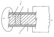
- inductor L 1is connected to conductive capacitor plates 2 and 4 as shown in the illustration of the relevant portions of an RF EAS tag 1 , according to one embodiment of the present invention.
- Capacitor plates 2 and 4 of capacitor C 1are separated by dielectric material 6 .
- Dielectric material 6can be an adhesive layer that retains plates 2 and 4 in their desired position.
- Inlaid in a cutout or void area of dielectric material 6is a matrix made of a conductive material in a nonconductive binder 8 .
- the conductive materialcan be any suitable conductive material that is adapted to be mixed with a binder, and can include, but is not limited to, a metal such as copper, aluminum, bronze, and the like, or a conductive material such as carbon.
- the nonconductive bindercan be made of, but is not limited to, varnish, polymers, polyurethane, and other nonconductive materials, the selection of which is well known in the art.
- the matrix of conductive material and nonconductive binder 8forms a carbonized or conductive path between capacitor plates 2 and 4 .
- the carbonized pathshorts plates 2 and 4 of capacitor C 1 rendering the EAS tag 1 non-resonant at its operating frequency, or deactivated.
- the field level required to resonate tag 1 for normal operationis lower than the magnitude required to short capacitor C 1 . Normal operation means that when tag 1 resonates it produces a signal detectable by an electronic article surveillance receiver (not shown). Deactivation occurs only when tag 1 is radiated with a field level of sufficient magnitude required for deactivation, which shorts plates 2 and 4 .
- inductor L 1may be formed by a coil of copper or other suitable conductor material on adhesive dielectric material 6 , which also carries conductor plate 2 of capacitor C 1 . Additional layers may be present, but are not shown. Inductor L 1 is connected to through contact 9 .
- FIG. 4a bottom plan view of the embodiment illustrated in FIG. 3 shows through contact 9 in electrical connection with conductor plate 4 of capacitor C 1 .
- the electrical circuitis thus completed as illustrated in FIG. 1 .
- additional layersmay be present, as well as other physical implementations of coil L 1 and capacitor plates 2 and 4 .
- conductive capacitor plates 12 and 14are both separated from dielectric material 6 by an oxide layer 16 .
- a conductive material 18which can be a conductive material as described hereinabove or another conductive material, is inlaid in an opening or void area in dielectric material 6 .
- Exposing tag 1 to an electromagnetic field of sufficient magnitude, frequency, and durationcauses a carbonizing path through oxide layer 16 between the conductive plates 12 and 14 and conductive material 18 .
- the resulting short circuit of capacitor C 1renders tag 10 non-resonating at the intended operating frequency, and deactivates tag 10 .
- one resonant frequency selectionis about 8 MHz, but the invention is not so limited and can be used at other frequencies.
- the desired deactivation electromagnetic fieldcan be a similar RF field but of relatively high magnitude, and can be an RF pulse.
- the inventioncan be implemented at other frequencies as long as a suitable shorting deactivation mechanism can be implemented by an electrically weakened area as disclosed herein.
Landscapes
- Physics & Mathematics (AREA)
- Engineering & Computer Science (AREA)
- Automation & Control Theory (AREA)
- Computer Security & Cryptography (AREA)
- Electromagnetism (AREA)
- General Physics & Mathematics (AREA)
- Burglar Alarm Systems (AREA)
Abstract
Description
Claims (8)
Priority Applications (7)
| Application Number | Priority Date | Filing Date | Title |
|---|---|---|---|
| US10/236,809US6919806B2 (en) | 2002-09-06 | 2002-09-06 | Deactivatable radio frequency security label |
| ARP030103125AAR041084A1 (en) | 2002-09-06 | 2003-08-28 | RADIO FREQUENCY SAFETY MARBET |
| PCT/US2003/027865WO2004023416A2 (en) | 2002-09-06 | 2003-09-05 | Deactivatable radio frequency security label |
| EP03794631AEP1540614A4 (en) | 2002-09-06 | 2003-09-05 | Deactivatable radio frequency security label |
| CA2496202ACA2496202C (en) | 2002-09-06 | 2003-09-05 | Deactivatable radio frequency security label |
| AU2003265946AAU2003265946A1 (en) | 2002-09-06 | 2003-09-05 | Deactivatable radio frequency security label |
| CN03821035.5ACN1679059A (en) | 2002-09-06 | 2003-09-05 | Deactivatable Radio Frequency Security Tags |
Applications Claiming Priority (1)
| Application Number | Priority Date | Filing Date | Title |
|---|---|---|---|
| US10/236,809US6919806B2 (en) | 2002-09-06 | 2002-09-06 | Deactivatable radio frequency security label |
Publications (2)
| Publication Number | Publication Date |
|---|---|
| US20040046665A1 US20040046665A1 (en) | 2004-03-11 |
| US6919806B2true US6919806B2 (en) | 2005-07-19 |
Family
ID=31977674
Family Applications (1)
| Application Number | Title | Priority Date | Filing Date |
|---|---|---|---|
| US10/236,809Expired - LifetimeUS6919806B2 (en) | 2002-09-06 | 2002-09-06 | Deactivatable radio frequency security label |
Country Status (7)
| Country | Link |
|---|---|
| US (1) | US6919806B2 (en) |
| EP (1) | EP1540614A4 (en) |
| CN (1) | CN1679059A (en) |
| AR (1) | AR041084A1 (en) |
| AU (1) | AU2003265946A1 (en) |
| CA (1) | CA2496202C (en) |
| WO (1) | WO2004023416A2 (en) |
Cited By (4)
| Publication number | Priority date | Publication date | Assignee | Title |
|---|---|---|---|---|
| US7286053B1 (en)* | 2004-07-31 | 2007-10-23 | Kovio, Inc. | Electronic article surveillance (EAS) tag/device with coplanar and/or multiple coil circuits, an EAS tag/device with two or more memory bits, and methods for tuning the resonant frequency of an RLC EAS tag/device |
| US20070279233A1 (en)* | 2006-06-01 | 2007-12-06 | Ccl Label, Inc. | Label with Removable RFID Portion |
| US20080174434A1 (en)* | 2007-01-18 | 2008-07-24 | Checkpoint Systems, Inc. | Permanently destructible resonant circuit with non-self-healing capacitor |
| US20130193215A1 (en)* | 2012-02-01 | 2013-08-01 | Checkpoint Systems, Inc. | Permanently deactivatable security tag |
Families Citing this family (5)
| Publication number | Priority date | Publication date | Assignee | Title |
|---|---|---|---|---|
| FR2848324B3 (en)* | 2002-12-06 | 2005-01-21 | Lionel Prat | DISPLACEMENT FLIGHT SECURITY DEVICE OF THE LABEL TYPE |
| EP1807814A1 (en)* | 2004-11-05 | 2007-07-18 | Qinetiq Limited | Detunable rf tags |
| GB0501199D0 (en)* | 2005-01-21 | 2005-03-02 | Qinetiq Ltd | Improved RF tags |
| WO2007000578A2 (en) | 2005-06-25 | 2007-01-04 | Omni-Id Limited | Electromagnetic radiation decoupler |
| US10380857B1 (en)* | 2018-03-05 | 2019-08-13 | Sensormatic Electronics, LLC | Systems and methods for radio frequency identification enabled deactivation of acousto-magnetic ferrite based marker |
Citations (10)
| Publication number | Priority date | Publication date | Assignee | Title |
|---|---|---|---|---|
| US4567473A (en) | 1982-05-10 | 1986-01-28 | Lichtblau G J | Resonant tag and deactivator for use in an electronic security system |
| US4682154A (en)* | 1986-02-12 | 1987-07-21 | E.A.S. Technologies, Inc. | Label for use in anti-theft surveillance system |
| US4802944A (en) | 1986-09-29 | 1989-02-07 | Monarch Marking Systems, Inc. | Method of making deactivatable tags |
| US5059950A (en) | 1990-09-04 | 1991-10-22 | Monarch Marking Systems, Inc. | Deactivatable electronic article surveillance tags, tag webs and method of making tag webs |
| US5754110A (en) | 1996-03-07 | 1998-05-19 | Checkpoint Systems, Inc. | Security tag and manufacturing method |
| US5841350A (en) | 1997-06-27 | 1998-11-24 | Checkpoint Systems, Inc. | Electronic security tag useful in electronic article indentification and surveillance system |
| US6091607A (en)* | 1998-12-10 | 2000-07-18 | Checkpoint Systems, Inc. | Resonant tag with a conductive composition closing an electrical circuit |
| US6400271B1 (en)* | 2000-03-20 | 2002-06-04 | Checkpoint Systems, Inc. | Activate/deactiveable security tag with enhanced electronic protection for use with an electronic security system |
| US6480110B2 (en)* | 2000-12-01 | 2002-11-12 | Microchip Technology Incorporated | Inductively tunable antenna for a radio frequency identification tag |
| US6549132B2 (en)* | 2000-06-19 | 2003-04-15 | Westvaco Packaging Group, Inc. | Deactivatable electronic article surveillance tag and method for making same |
Family Cites Families (2)
| Publication number | Priority date | Publication date | Assignee | Title |
|---|---|---|---|---|
| CH680823A5 (en)* | 1990-08-17 | 1992-11-13 | Kobe Properties Ltd | |
| DK166176C (en)* | 1990-11-23 | 1993-08-09 | Poul Richter Joergensen | PROCEDURE FOR MANUFACTURING CIRCULAR LABELS WITH A CIRCUIT CIRCUIT WHICH CAN BE ACTIVATED AND DISABLED |
- 2002
- 2002-09-06USUS10/236,809patent/US6919806B2/ennot_activeExpired - Lifetime
- 2003
- 2003-08-28ARARP030103125Apatent/AR041084A1/enactiveIP Right Grant
- 2003-09-05EPEP03794631Apatent/EP1540614A4/enactivePending
- 2003-09-05WOPCT/US2003/027865patent/WO2004023416A2/ennot_activeApplication Discontinuation
- 2003-09-05AUAU2003265946Apatent/AU2003265946A1/ennot_activeAbandoned
- 2003-09-05CACA2496202Apatent/CA2496202C/ennot_activeExpired - Fee Related
- 2003-09-05CNCN03821035.5Apatent/CN1679059A/enactivePending
Patent Citations (10)
| Publication number | Priority date | Publication date | Assignee | Title |
|---|---|---|---|---|
| US4567473A (en) | 1982-05-10 | 1986-01-28 | Lichtblau G J | Resonant tag and deactivator for use in an electronic security system |
| US4682154A (en)* | 1986-02-12 | 1987-07-21 | E.A.S. Technologies, Inc. | Label for use in anti-theft surveillance system |
| US4802944A (en) | 1986-09-29 | 1989-02-07 | Monarch Marking Systems, Inc. | Method of making deactivatable tags |
| US5059950A (en) | 1990-09-04 | 1991-10-22 | Monarch Marking Systems, Inc. | Deactivatable electronic article surveillance tags, tag webs and method of making tag webs |
| US5754110A (en) | 1996-03-07 | 1998-05-19 | Checkpoint Systems, Inc. | Security tag and manufacturing method |
| US5841350A (en) | 1997-06-27 | 1998-11-24 | Checkpoint Systems, Inc. | Electronic security tag useful in electronic article indentification and surveillance system |
| US6091607A (en)* | 1998-12-10 | 2000-07-18 | Checkpoint Systems, Inc. | Resonant tag with a conductive composition closing an electrical circuit |
| US6400271B1 (en)* | 2000-03-20 | 2002-06-04 | Checkpoint Systems, Inc. | Activate/deactiveable security tag with enhanced electronic protection for use with an electronic security system |
| US6549132B2 (en)* | 2000-06-19 | 2003-04-15 | Westvaco Packaging Group, Inc. | Deactivatable electronic article surveillance tag and method for making same |
| US6480110B2 (en)* | 2000-12-01 | 2002-11-12 | Microchip Technology Incorporated | Inductively tunable antenna for a radio frequency identification tag |
Cited By (7)
| Publication number | Priority date | Publication date | Assignee | Title |
|---|---|---|---|---|
| US7286053B1 (en)* | 2004-07-31 | 2007-10-23 | Kovio, Inc. | Electronic article surveillance (EAS) tag/device with coplanar and/or multiple coil circuits, an EAS tag/device with two or more memory bits, and methods for tuning the resonant frequency of an RLC EAS tag/device |
| US7498948B1 (en) | 2004-07-31 | 2009-03-03 | Kovio, Inc. | Electronic article surveillance (EAS) tag/device with coplanar and/or multiple coil circuits, an EAS tag/device with two or more memory bits, and methods for tuning the resonant frequency of an RLC EAS tag/device |
| US20070279233A1 (en)* | 2006-06-01 | 2007-12-06 | Ccl Label, Inc. | Label with Removable RFID Portion |
| US7425898B2 (en) | 2006-06-01 | 2008-09-16 | Ccl Label, Inc. | Label with removable RFID portion |
| US20080174434A1 (en)* | 2007-01-18 | 2008-07-24 | Checkpoint Systems, Inc. | Permanently destructible resonant circuit with non-self-healing capacitor |
| US20130193215A1 (en)* | 2012-02-01 | 2013-08-01 | Checkpoint Systems, Inc. | Permanently deactivatable security tag |
| US8985467B2 (en)* | 2012-02-01 | 2015-03-24 | Checkpoint Systems, Inc. | Permanently deactivatable security tag |
Also Published As
| Publication number | Publication date |
|---|---|
| US20040046665A1 (en) | 2004-03-11 |
| WO2004023416A3 (en) | 2004-11-25 |
| AU2003265946A1 (en) | 2004-03-29 |
| CA2496202A1 (en) | 2004-03-18 |
| WO2004023416A2 (en) | 2004-03-18 |
| CN1679059A (en) | 2005-10-05 |
| AU2003265946A8 (en) | 2004-03-29 |
| AR041084A1 (en) | 2005-04-27 |
| EP1540614A2 (en) | 2005-06-15 |
| EP1540614A4 (en) | 2005-10-12 |
| CA2496202C (en) | 2012-03-06 |
Similar Documents
| Publication | Publication Date | Title |
|---|---|---|
| US5276431A (en) | Security tag for use with article having inherent capacitance | |
| CA2064001C (en) | Activatable/deactivatable security tag for use with an electronic security system | |
| US4835524A (en) | Deactivatable security tag | |
| US6400271B1 (en) | Activate/deactiveable security tag with enhanced electronic protection for use with an electronic security system | |
| EP0714540B1 (en) | Multiple frequency tag | |
| JP3940187B2 (en) | Security tag that can be disabled | |
| KR100832919B1 (en) | Integrated Hybrid Electronic Surveillance Markers | |
| US5182544A (en) | Security tag with electrostatic protection | |
| AU2001240056A2 (en) | Activatable/deactivatable security tag with enhanced electrostatic protection for use with an electronic security system | |
| AU2001240056A1 (en) | Activatable/deactivatable security tag with enhanced electrostatic protection for use with an electronic security system | |
| US6919806B2 (en) | Deactivatable radio frequency security label | |
| HK1082087A (en) | Deactivatable radio frequency security label | |
| MXPA00002812A (en) | Deactivateable resonant circuit |
Legal Events
| Date | Code | Title | Description |
|---|---|---|---|
| AS | Assignment | Owner name:SENSORMATIC ELECTRONICS CORPORATION, FLORIDA Free format text:ASSIGNMENT OF ASSIGNORS INTEREST;ASSIGNORS:NARLOW, DOUGLAS;PATTERSON, HUBERT A.;REEL/FRAME:013274/0785 Effective date:20020906 | |
| STCF | Information on status: patent grant | Free format text:PATENTED CASE | |
| FPAY | Fee payment | Year of fee payment:4 | |
| AS | Assignment | Owner name:SENSORMATIC ELECTRONICS, LLC,FLORIDA Free format text:MERGER;ASSIGNOR:SENSORMATIC ELECTRONICS CORPORATION;REEL/FRAME:024213/0049 Effective date:20090922 Owner name:SENSORMATIC ELECTRONICS, LLC, FLORIDA Free format text:MERGER;ASSIGNOR:SENSORMATIC ELECTRONICS CORPORATION;REEL/FRAME:024213/0049 Effective date:20090922 | |
| FPAY | Fee payment | Year of fee payment:8 | |
| AS | Assignment | Owner name:ADT SERVICES GMBH, SWITZERLAND Free format text:ASSIGNMENT OF ASSIGNORS INTEREST;ASSIGNOR:SENSORMATIC ELECTRONICS, LLC;REEL/FRAME:029894/0856 Effective date:20130214 | |
| AS | Assignment | Owner name:TYCO FIRE & SECURITY GMBH, SWITZERLAND Free format text:MERGER;ASSIGNOR:ADT SERVICES GMBH;REEL/FRAME:030290/0731 Effective date:20130326 | |
| FPAY | Fee payment | Year of fee payment:12 | |
| AS | Assignment | Owner name:SENSORMATIC ELECTRONICS, LLC, FLORIDA Free format text:ASSIGNMENT OF ASSIGNORS INTEREST;ASSIGNOR:TYCO FIRE & SECURITY GMBH;REEL/FRAME:047182/0674 Effective date:20180927 | |
| AS | Assignment | Owner name:SENSORMATIC ELECTRONICS, LLC, FLORIDA Free format text:ASSIGNMENT OF ASSIGNORS INTEREST;ASSIGNOR:TYCO FIRE & SECURITY GMBH;REEL/FRAME:047188/0715 Effective date:20180927 |