US6917855B2 - Real-time target tracking of an unpredictable target amid unknown obstacles - Google Patents
Real-time target tracking of an unpredictable target amid unknown obstaclesDownload PDFInfo
- Publication number
- US6917855B2 US6917855B2US10/435,934US43593403AUS6917855B2US 6917855 B2US6917855 B2US 6917855B2US 43593403 AUS43593403 AUS 43593403AUS 6917855 B2US6917855 B2US 6917855B2
- Authority
- US
- United States
- Prior art keywords
- escape
- target
- risk
- path
- observer robot
- Prior art date
- Legal status (The legal status is an assumption and is not a legal conclusion. Google has not performed a legal analysis and makes no representation as to the accuracy of the status listed.)
- Expired - Lifetime, expires
Links
- 230000033001locomotionEffects0.000claimsabstractdescription56
- 238000004364calculation methodMethods0.000claimsdescription29
- 238000000034methodMethods0.000claimsdescription27
- 238000001514detection methodMethods0.000claimsdescription15
- 241000124008MammaliaSpecies0.000claims1
- 238000005259measurementMethods0.000abstractdescription8
- 230000006870functionEffects0.000description23
- 230000009471actionEffects0.000description20
- 230000000007visual effectEffects0.000description7
- 230000007704transitionEffects0.000description6
- 238000013459approachMethods0.000description4
- 230000008859changeEffects0.000description4
- 238000007796conventional methodMethods0.000description3
- 230000008569processEffects0.000description3
- 230000008901benefitEffects0.000description2
- 230000007423decreaseEffects0.000description2
- 230000001419dependent effectEffects0.000description2
- 238000010586diagramMethods0.000description2
- 230000004807localizationEffects0.000description2
- 238000013507mappingMethods0.000description2
- 230000007246mechanismEffects0.000description2
- 239000007787solidSubstances0.000description2
- 241001465754MetazoaSpecies0.000description1
- 230000002411adverseEffects0.000description1
- 230000004931aggregating effectEffects0.000description1
- 230000003042antagnostic effectEffects0.000description1
- 238000010420art techniqueMethods0.000description1
- 238000010276constructionMethods0.000description1
- 238000013461designMethods0.000description1
- 230000000694effectsEffects0.000description1
- 238000002474experimental methodMethods0.000description1
- 238000009472formulationMethods0.000description1
- 238000003384imaging methodMethods0.000description1
- 230000001524infective effectEffects0.000description1
- 239000000203mixtureSubstances0.000description1
- 238000012544monitoring processMethods0.000description1
- 210000000056organAnatomy0.000description1
- 238000012545processingMethods0.000description1
- 238000009877renderingMethods0.000description1
- 238000000926separation methodMethods0.000description1
- 239000000779smokeSubstances0.000description1
- 238000001356surgical procedureMethods0.000description1
- 230000001052transient effectEffects0.000description1
- 238000011179visual inspectionMethods0.000description1
Images


Classifications
- G—PHYSICS
- G05—CONTROLLING; REGULATING
- G05D—SYSTEMS FOR CONTROLLING OR REGULATING NON-ELECTRIC VARIABLES
- G05D1/00—Control of position, course, altitude or attitude of land, water, air or space vehicles, e.g. using automatic pilots
- G05D1/12—Target-seeking control
- G—PHYSICS
- G05—CONTROLLING; REGULATING
- G05D—SYSTEMS FOR CONTROLLING OR REGULATING NON-ELECTRIC VARIABLES
- G05D1/00—Control of position, course, altitude or attitude of land, water, air or space vehicles, e.g. using automatic pilots
- G05D1/0094—Control of position, course, altitude or attitude of land, water, air or space vehicles, e.g. using automatic pilots involving pointing a payload, e.g. camera, weapon, sensor, towards a fixed or moving target
- G—PHYSICS
- G05—CONTROLLING; REGULATING
- G05D—SYSTEMS FOR CONTROLLING OR REGULATING NON-ELECTRIC VARIABLES
- G05D1/00—Control of position, course, altitude or attitude of land, water, air or space vehicles, e.g. using automatic pilots
- G05D1/02—Control of position or course in two dimensions
- G05D1/021—Control of position or course in two dimensions specially adapted to land vehicles
- G05D1/0268—Control of position or course in two dimensions specially adapted to land vehicles using internal positioning means
- G05D1/0274—Control of position or course in two dimensions specially adapted to land vehicles using internal positioning means using mapping information stored in a memory device
- G—PHYSICS
- G05—CONTROLLING; REGULATING
- G05D—SYSTEMS FOR CONTROLLING OR REGULATING NON-ELECTRIC VARIABLES
- G05D1/00—Control of position, course, altitude or attitude of land, water, air or space vehicles, e.g. using automatic pilots
- G05D1/02—Control of position or course in two dimensions
- G05D1/021—Control of position or course in two dimensions specially adapted to land vehicles
- G05D1/0212—Control of position or course in two dimensions specially adapted to land vehicles with means for defining a desired trajectory
- G05D1/0217—Control of position or course in two dimensions specially adapted to land vehicles with means for defining a desired trajectory in accordance with energy consumption, time reduction or distance reduction criteria
- G—PHYSICS
- G05—CONTROLLING; REGULATING
- G05D—SYSTEMS FOR CONTROLLING OR REGULATING NON-ELECTRIC VARIABLES
- G05D1/00—Control of position, course, altitude or attitude of land, water, air or space vehicles, e.g. using automatic pilots
- G05D1/02—Control of position or course in two dimensions
- G05D1/021—Control of position or course in two dimensions specially adapted to land vehicles
- G05D1/0231—Control of position or course in two dimensions specially adapted to land vehicles using optical position detecting means
- G05D1/0238—Control of position or course in two dimensions specially adapted to land vehicles using optical position detecting means using obstacle or wall sensors
- G05D1/024—Control of position or course in two dimensions specially adapted to land vehicles using optical position detecting means using obstacle or wall sensors in combination with a laser
- G—PHYSICS
- G05—CONTROLLING; REGULATING
- G05D—SYSTEMS FOR CONTROLLING OR REGULATING NON-ELECTRIC VARIABLES
- G05D1/00—Control of position, course, altitude or attitude of land, water, air or space vehicles, e.g. using automatic pilots
- G05D1/02—Control of position or course in two dimensions
- G05D1/021—Control of position or course in two dimensions specially adapted to land vehicles
- G05D1/0231—Control of position or course in two dimensions specially adapted to land vehicles using optical position detecting means
- G05D1/0246—Control of position or course in two dimensions specially adapted to land vehicles using optical position detecting means using a video camera in combination with image processing means
- G—PHYSICS
- G05—CONTROLLING; REGULATING
- G05D—SYSTEMS FOR CONTROLLING OR REGULATING NON-ELECTRIC VARIABLES
- G05D1/00—Control of position, course, altitude or attitude of land, water, air or space vehicles, e.g. using automatic pilots
- G05D1/02—Control of position or course in two dimensions
- G05D1/021—Control of position or course in two dimensions specially adapted to land vehicles
- G05D1/0268—Control of position or course in two dimensions specially adapted to land vehicles using internal positioning means
- G05D1/0272—Control of position or course in two dimensions specially adapted to land vehicles using internal positioning means comprising means for registering the travel distance, e.g. revolutions of wheels
Definitions
- the present inventionrelates to robotic systems having a target tracking capability. More specifically, the present invention relates to a target tracking algorithm that provides, among other things, real-time tracking of an unpredictable target located amid unknown obstacles.
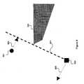
- FIG. 1illustrates an observer robot 103 following a moving target 101 through a workspace 100 .
- the observer robot 103includes a sensor that provides it with a localized visibility region 109 of the workspace 100 .
- the observer robot 103has no prior knowledge of the workspace 100 or the target's trajectory. Accordingly, the observer robot 103 wants to keep the target 101 within the visibility region 109 in order to track changes in the target's movement. Complicating the observer robot's task are various obstacles 105 , 111 and occlusions produced by those obstacles.
- the observer robot 103will not be able to identify the target 103 in the visibility region 109 and will likely lose track of the target 101 altogether. While the workspace 100 is shown in FIG. 1 as a bounded area, the workspace 100 is theoretically unbounded.
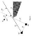
- FIG. 2illustrates a problem that arises when the tracking algorithm used by the observer robot 103 employs only visual servoing to follow the target 101 .
- Sensors associated with the observer robotproduce visibility regions 109 a - 109 c .
- the observer robot 103identifies the target 101 in each of the visibility regions 109 a - 109 c and moves progressively from location 103 a to location 103 c as the target moves from location 101 a to 101 c .
- the target's trajectorypasses behind the edge to location 101 d . From visibility region 109 d , the observer robot 103 will not be able to identify the target 101 due to the edge of obstacle 111 .
- the observer robot's visual servoing controlwill not know what steering command to next render to the observer robot 103 .
- the observer robot 103will likely lose track of the target 101 unless the target's trajectory just happens to take it past the interposing obstacle 111 .
- the tracking problem presented in FIG. 2somewhat resembles the problem that a large hauling truck faces while trying to round a corner without passing over the curb of the near-side street.
- the observer robot 103cannot see through the obstacle 111 and cannot pass over it either. Accordingly, pure visual servoing does not provide an appropriate solution for workspaces like the workspace 100 .
- Tracking problemshave been encountered in various other disciplines. However, avoiding occlusions are not typically a concern of the tracking solution. For instance, missile control systems do not typically need to solve occlusion problems. Similarly, tracking targets through obstacles in known environments is not typically a major problem. If the observer robot has a priori knowledge of the workspace, it can react to trajectories selected by the target. For instance, the prior art includes solutions to problems known as “guarding the art gallery” in which a target having an unknown trajectory moves through a workspace (e.g., an art gallery) similar to that shown in FIG. 1 . In this problem, fixed sensors at various locations in the workspace are used to track the moving target.
- guarding the art galleryin which a target having an unknown trajectory moves through a workspace (e.g., an art gallery) similar to that shown in FIG. 1 . In this problem, fixed sensors at various locations in the workspace are used to track the moving target.
- the fixed sensorstypically have knowledge of the workspace and knowledge about the location of the other fixed sensors.
- the observer robothas a prior knowledge of the target's trajectory, it can plan for the target's movements and is less reliant upon sensor data.
- Prior knowledgeeven allows solutions to be developed off-line and even outside the observer robot using more powerful computing devices than those likely to be available in a small robot.
- on-line game-theoretic planning solutionsinvolve preparing probabilistic models of a target's behavior and typically include prior knowledge of the workspace.
- solutionsare typically computationally intense and may not be suitable for implementation in many robotic applications.
- a solutionis needed for the problem of tracking targets having unknown trajectories through an unknown workspace by a mobile observer robot.
- the solutionshould be sufficiently elegant so as to minimize the impact on the computational resources of the mobile observer robot.
- Embodiments of the inventionprovide a strategy for computing the motions of an observer robot tracking a target in an unknown environment and with no prior knowledge of the target's intentions or the distribution of obstacles in the environment.
- Embodiments of the inventionprovide an algorithm that governs the motion of the observer robot based on measurements of the target's position and the location of obstacles in the environment. The algorithm computes a description of the geometric arrangement between the target and the observer's visibility region produced by the obstacles and computes a continuous control rule using this description.
- Embodiments of the inventionprovide a method for tracking a target moving among a plurality of obstacles in a workspace.
- the methodcalls for preparing a visibility region that identifies the locations of obstacles from the plurality of obstacles and identifies the location of the target using data received from a sensor.
- a plurality of escape paths for the targetare calculated using the visibility region, each escape path representing a route that would occlude the target from future detection by the sensor.
- An escape path set from among the plurality of escape pathsis identified such that the escape path set represents escape routes having the shortest length.
- An escape risk gradientis calculated for the escape path set that can be used to prepare a steering command for an observer robot tracking the target.
- Embodiments of the inventionalso provide a system for tracking a target moving among a plurality of obstacles in a workspace.
- the systemincludes a visibility acquisition module configured to prepare a visibility region that identifies locations of obstacles from the plurality of obstacles using data received from a sensor.
- a target acquisition moduleis configured to locate the target in the visibility region.
- An escape-path tree building moduleidentifies a plurality of escape paths for the target using the visibility region, each escape path representing a route that would occlude the target from further detection by the sensor.
- a shortest escape-path tree calculation moduleis configured to identify an escape path set from among the plurality of escape paths such that the escape path set represents the routes having the shortest length.
- a risk gradient calculation modulecalculates an escape risk gradient for the escape path set that can be provided to an observer robot tracking the target.
- Embodiments of the inventionfurther provide a method for tracking a target in a workspace.
- the methodcalls for sensing the workspace to obtain a visibility region that identifies the target and at least one obstacle.
- An escape riskis calculated from the visibility region, the escape risk representing the risk that a trajectory of the target will escape further detection from an observer robot. Escape from the observer robot includes movement outside the visibility region and movement into an occlusion produced by the at least one obstacle.
- a steering command for the observer robotcan be composed using the escape risk. The steering command reduces the target's ability to escape detection from the observer robot.
- Embodiments of the inventionalso provide a system for tracking a target in a workspace.
- a sensorobtains data that describes the workspace.
- a visibility region acquisition moduleuses data received from the sensor to produce a visibility region that identifies a plurality of obstacles in the workspace.
- a target acquisition moduleis configured to identify the target in the workspace.
- a risk association moduleuses the visibility region to determine an escape risk that the target will escape detection from an observer robot, where escape from the observer robot includes both target movement outside the visibility region and target movement into an occlusion produced by at least one obstacle of the plurality of obstacles.
- a motion command calculation modulecomposes a steering command for the observer robot that reduces a target's ability to escape detection from the observer robot.
- Embodiments of the inventionfurther provide a method for tracking a target moving in a workspace.
- the methodcalls for preparing an escape-path tree having the target as a head node.
- a plurality of escape pathsare identified for the target, each escape path representing a route through the workspace that would occlude the target from at least one sensor.
- Each escape path of the plurality of escape pathsis placed as a child node in the escape-path tree, and each escape path is ordered in the escape-path tree such that escape paths having shorter lengths reside higher in the escape-path tree than escape paths having longer lengths.
- a set of escape paths having shorter lengthsis selected from the escape-path tree.
- An escape risk for the targetis calculated using the set of escape paths.
- Embodiments of the inventionalso provide a system for tracking a target moving in a workspace.
- An escape-path tree building moduleis configured to prepare an escape-path tree having the target as a head node and identify a plurality of escape paths for the target, where each escape path represents a route through the workspace that would occlude the target from at least one sensor.
- the building moduleis also configured to place each escape path of the plurality of escape paths as a child node in the escape-path tree and order the escape paths in the tree such that escape paths having shorter lengths reside higher in the escape-path tree than escape paths having longer lengths.
- a shortest escape-path tree calculation moduleselects a set of escape paths having shorter lengths from the escape-path tree.
- a risk association moduleis configured to calculate an escape risk for the target using the selected set of escape paths.
- Embodiments of the inventionalso provide a computer readable medium that comprises an escape-path tree data structure, location data for the target, and location data for an observer robot tracking the target.
- the escape-path tree data structureis configured to represent escape paths that the target could use to escape detection by a sensor.
- FIG. 1illustrates a mobile observer robot following a moving target through a workspace.
- FIG. 2illustrates a problem that arises when the tracking algorithm used by the observer robot employs only visual servoing to follow the target.
- FIG. 3illustrates the movements of an observer robot applying a tracking algorithm to follow a moving target as it moves around an obstacle, according to an embodiment of the invention.
- FIG. 4is a flowchart that depicts the steps performed by the tracking algorithm, according to an embodiment of the invention.
- FIG. 5illustrates sensor data supplied to the track algorithm by a sensor that can be used to determine the visibility region and locate the target, according to an embodiment of the invention.
- FIG. 6illustrates a visibility region containing obstacles identified by the track algorithm, according to an embodiment of the invention.
- FIG. 7illustrates a first step in the transition of the visibility region into an escape path tree (“EPT”), according to an embodiment of the invention.
- EPTescape path tree
- FIG. 8illustrates an escape-path tree imposed over the visibility region, according to an embodiment of the invention.
- FIG. 9illustrates some initial considerations for a tracking algorithm's risk-based strategy, according to an embodiment of the invention.
- FIG. 10illustrates further movement of the target towards the occlusion created by the obstacle and the role of the reactive component, according to an embodiment of the invention.
- FIG. 11illustrates the combination of the reactive component and a look-ahead component and into a trajectory for the observer robot, according to an embodiment of the invention.
- FIG. 12further illustrates the role of the look-ahead component by providing an example in which the target is on the same side of the obstacle as the observer robot.
- FIG. 13is a block diagram of an observer robot configured to perform the tracking algorithm, according to an embodiment of the invention.
- Embodiments of the inventionprovide a strategy for computing the motions of a mobile robot operating without prior knowledge of the target's intentions or the distribution of obstacles in the environment.
- Embodiments of the inventionalso provide an algorithm that governs the motion of the observer robot based on measurements of the target's position and the location of obstacles in the environment. The algorithm computes a description of the geometric arrangement between the target and the observer's visibility region produced by the obstacles and computes a continuous control rule using this description.
- FIG. 3illustrates the movements of an observer robot 303 applying a tracking algorithm to follow a moving target 301 as it moves around an obstacle 111 , according to an embodiment of the invention.
- the target 301could be any moving object, from a robot, to a mechanical device, to an animal, such as a human.
- the observer robot 303receives data from a controllable sensor.
- the observer robot 303may include a controllable vision sensor mounted on the robot, as well as software that executes the tracking algorithm.
- the observer robot 303need not know the target's trajectory in advance in order for the tracking algorithm to provide appropriate instructions to the observer robot 303 .
- the observer robot 303also requires no prior model, or map, of a workspace 305 and does not know the location of obstacles, such as the obstacle 111 . Accordingly, the tracking algorithm aims to avoid sensor (e.g., visual) separation between the observer robot 303 and the moving target 301 .
- the tracking algorithmassumes that any obstacle in the workspace 305 that obstructs the observer robot's field of view also constrains the motions of both the observer robot 303 and the target 301 , and vice-versa (e.g., no transparent objects or smoke screens), according to an embodiment of the invention.
- the observer robot 303determines a visibility region 309 a - 309 e (e.g., a local map) for the workspace 301 .
- the observer robot 303relies on the visibility region 309 a - 309 e , computed on-the-fly from the measurements, produced by its sensor in an embodiment of the invention, to determine its own trajectory while following the target 303 .
- the observer robot's tracking algorithmdetermines that if the target 301 moves around obstacle 111 , then the observer robot 303 will lose sensor contact with the target 301 . Accordingly, and in contrast to the observer robot motion shown in FIG.
- the observer robot 303moves slightly away from the obstacle 111 as the observer robot 303 tracks the target 301 .
- the observer robot 303does not lose sensor contact with the target 303 , as shown by the sensor sweep indicated in visibility region 309 e.
- the observer robot's tracking algorithmis analogous to the actions of a person tracking a moving target in an unknown environment using a flashlight that projects only a plane of light. Moreover, the person's flashlight flickers on and off and the person cannot assume that if they lose sight of the target that they can re-locate the target by running after it. The interested reader will find a detailed mathematical description of the tracking problem and its solution following FIG. 13 .
- the tracking algorithmneeds to account for the geometry of the workspace 305 .
- obstaclesconstrain the area of the workspace 305 that is visible to the observer robot 303 .
- the observer robot 303cannot see around the corner of obstacle 111 , which is why the tracking algorithm causes the observer robot's movements from positions 303 a - 303 c to move slightly away from the obstacle 111 and facilitate the observer robot's goal of staying in sensor contact with the target 301 .
- the observer robot's equipment configurationdetermines the field of view of its sensors.
- the observer robot's visibilitymay be limited to a fixed cone (of various sizes) or restricted by lower and/or upper bounds on the sensor range.
- the visibility regions shown in FIG. 3comprise the sectors shown as 309 a - 309 e .
- the tracking algorithmcan compute the visibility region from a synthetic model or from sensor measurements. In the former case, a ray-sweep algorithm can be used to compute the visibility region for conventional polygonal models. For the latter, the visibility region can be measured with a laser range-finder using conventional techniques. A suitable ray-sweep algorithm is discussed in the detailed mathematical description following FIG. 13 .
- Target trackingcomprises computing a function—a tracking strategy—such that the target 301 remains in view by the observer robot 303 at all times. Additionally, the tracking strategy may optimize other criteria, such as the total distance traversed by the observer robot 303 , the distance from the observer 303 to the target 301 , or a quality measure of the sensor information. In some embodiments, losing track of the target 303 may be unavoidable, in which case an optimal tracking strategy may comprise maximizing the target's “escape time” or “time to escape” (t esc )—the time when the observer robot 303 first loses the target 301 . For example, as shown in FIG. 2 , the escape time is the instant when the target's movement interposes the obstacle 111 between the target 301 and the observer robot 303 .
- the target 301is said to be “predictable.” In such cases, the optimal tracking strategy can typically be calculated off-line before the observer robot 303 begins to track the target 301 . Because the location of the target 301 is known for all times, the observer robot 303 may re-acquire the target 301 if it becomes lost. For cases where it is impossible to track the target 301 for all times, an alternative is to maximize the “exposure”—the total time the target 301 is visible to the observer robot 303 —as an alternative to maximizing the escape time. For example, as shown in FIG. 2 , the exposure of the observer robot 103 to the target 101 roughly corresponds to the observer robot's positions 103 a - 103 c.
- the tracking strategyis computed as a function of the target's state at a particular time, then the strategy operates in a closed loop. Otherwise, the tracking strategy runs in open loop. Closed-loop strategies are typically preferred over open-loop ones even for predictable cases, unless there is a guarantee that the target's motion models and position measurements are exact.
- FIGS. 2 and 3both illustrate the movement of unpredictable targets.
- the unpredictable casecan be analyzed in two ways. If the target actions are modeled as “nondeterministic uncertainty,” then it is assumed that the target's set of possible actions is known but not the specific action to be taken at a specific time. Thus, the action set is known but not the specific action selected by the target 301 at any instance. In this case, a tracking strategy can be designed that performs the best given the worst-case choices for each given time. Alternatively, if a “probabilistic uncertainty” model is available (e.g., the probability density function is known), then it is possible to compute a motion plan that is the best in the expected sense.
- a “probabilistic uncertainty” modele.g., the probability density function is known
- a good tracking algorithm in the observer robot 303seeks to maximize the escape time as opposed to maximizing the exposure.
- a strategy designed for the worst-case scenarioanticipates the target's most adverse action for a future time horizon, executes a small (possibly differential) initial portion of the computed tracking strategy, and repeats the entire process again.
- a tracking strategy designed to anticipate the expected target's actionseeks to maximize the probability of future sensor visibility of the target 301 to the observer robot 303 .
- Worst-case tracking based on maximizing the time to escapeis especially suitable for antagonistic targets that actively try to avoid the observer robot. Solving this tracking problem can be computationally expensive, especially in a small robot.
- Embodiments of the inventionuse the notion of escape risk as a proxy function of the escape time. As will be described, the gradient of the escape risk can be computed analytically resulting in a fast tracking algorithm.
- FIG. 4is a flowchart that depicts the steps performed by the tracking algorithm, according to an embodiment of the invention.
- the tracking algorithmminimizes for the observer robot (e.g., the observer robot 303 shown in FIG. 3 ) the risk that the target (e.g., the target 301 shown in FIG. 3 ) may escape the observer robot's visibility region.
- the tracking algorithmrequires no prior model of the workspace (e.g., the workspace 305 shown in FIG. 3 ).
- the tracking algorithmaccommodates transient targets having unknown trajectories.
- the tracking algorithmcombines both a reactive term and a look-ahead term that together improve the observer robot's ability to stay in contact with the target.
- the tracking algorithmhas been experimentally shown to work well with aggressive targets having highly unpredictable trajectories.
- the tracking algorithmrepeatedly performs steps 401 - 411 .
- the track algorithmevaluates the change in the risk of the target's escape ( ⁇ ) at each time step using two geometric computations.
- the track algorithmacquires 401 a visibility region (e.g., the visibility region 309 a shown in FIG. 3 ) of the workspace.
- Step 401yields the observer robot's visibility region (e.g., region 309 a ) in the workspace (e.g., the workspace 305 shown in FIG. 3 ).
- the sensor's characteristicse.g., its minimum and maximum range
- This visibility datamay also be supplied to the track algorithm in other ways (e.g., from other sensors in the workspace). Having its visibility data, the track algorithm can locate 403 the target (e.g., the target 301 shown in FIG. 3 ) within the visibility region.
- the targete.g., the target 301 shown in FIG. 3
- the specific choice of methods for obstacle and target detectionis typically application dependent.
- a second geometric computation 405produces the escape-path tree (“EPT”), a data structure containing the worst-case paths that the target may select to escape from the observer's visibility region.
- EPTescape-path tree
- the track algorithmuses the target's location, calculates a shortest escape path for the target.
- the track algorithmnext associates an escape risk 407 with the shortest escape paths for the target using information from the EPT. Calculation and use of the EPT are discussed in greater detail below.
- the track algorithmnext computes 409 a risk gradient. Differential changes in the observer robot's position typically produce differential changes in the EPT, which in turn produces differential changes in the risk ⁇ . Because the track algorithm may compute-this differential change analytically, then the gradient of ⁇ can be used to direct the motion of the observer robot. This approach provides an on-line strategy for controlling mobile robots, as well as a differential strategy (e.g., a feedback controller).
- the escape risk gradient computationcomprises determining ⁇ e for each free edge e in the workspace, where ⁇ e is a measure of the target's escape risk associated to the free edge e.
- the risk gradient computationcomprises calculating ⁇ overscore ( ⁇ ) ⁇ using the escape-path tree prepared in step 405 .
- the track algorithmthen computes 411 a motion command for the observer robot (e.g., the observer robot 303 shown in FIG. 3 ) as a recursive average of the risk gradients.
- the observer robotcan then be steered using ⁇ overscore ( ⁇ ) ⁇ as a robot control.
- Steps 401 - 411 of the track algorithmhave been shown sequentially in FIG. 4 for clarity purposes. However, it is typically more efficient in actual implementations to intermingle some of these steps. Steps 401 - 403 and 411 are implementation dependent. Acquiring location and target data depends upon the sensor(s) deployed, and steering control for the robot depends upon the design specifications of the actual robot used. Step 407 comprises evaluating the gradient of an escape equation (to be discussed below) for the escape paths. Step 409 comprises computing a recursive average of the risks of the various escape paths in the EPT developed in step 405 .
- step 405greatly influences the performance of the tracking algorithm as a whole.
- the computation of the EPTshould be performed efficiently.
- a ray-sweep algorithmrepresents a suitable approach to efficient performance of the EPT, according to an embodiment of the invention. The characteristics of an appropriate ray-sweep algorithm are provided below.
- the track algorithmredirects the observer robot (e.g., the observer robot 303 shown in FIG. 3 ) several times per second based on the differential change in a measure ⁇ of the risk that the target escapes its field of view, according to an embodiment of the invention.
- the track algorithmcomputes ⁇ deterministically as a function of how quickly the target can escape and how easy it is for the observer robot to react to such an event. For example, if the target can escape by moving around a corner (e.g., the obstacle 111 shown in FIG. 3 ), then ⁇ grows with the distance between the observer robot and the corner. This approach acknowledges that occlusions may be difficult to clear if the observer robot is far away from the edge that produces the occlusion.
- FIGS. 5-8provide additional information on acquisition of the visibility region, location of the target, construction of the EPT, and determination of the shortest escape paths.
- FIG. 5illustrates sensor data 509 supplied to the track algorithm by a sensor 503 that can be used to determine the visibility region (e.g., the visibility region 309 a shown in FIG. 3 ) and locate the target, according to an embodiment of the invention.
- the illustrated sensor data 509represents a single plane of information about the workspace.
- the track algorithmmay use the sensor data 509 to determine the observer robot's visibility region by identifying obstacles 501 a - 501 b and identifying the target 301 .
- the track algorithmhas already identified the target, as indicated by the smooth circle placed around the target 301 .
- identification of the targetmay be simplified when some characteristics of the target are known to the track algorithm.
- the track algorithmmay more easily identify the target than in the absence of such information.
- the jagged marks showing obstacles 501 a - 501 bindicate that the track algorithm has not yet identified this sensor data as “obstacles” in the visibility region.
- FIG. 6illustrates the visibility region 609 containing obstacles 601 a - 601 e identified by the track algorithm, according to an embodiment of the invention.
- the obstacles 601 a - 601 econstitute escape risks in that the observer robot may lose sensor contact with the target should one of the obstacles become interposed between the observer and the target.
- the visibility region 609provides the track algorithm with an instantaneous map of the workspace (or at least the portion of the workspace recognizable by the observer robot's sensors).
- FIG. 7illustrates a first step in the transition of the visibility region 609 into an escape path tree (“EPT”), according to an embodiment of the invention.
- the track algorithmcan next determine the possible occlusions 703 a - 703 f represented by those obstacles. For example, based on the observer robot's position if the target 301 passed into occlusion 703 a , then the observer robot 303 would lose track of the target 301 due to the obstacle 601 b .
- the region represented by each occlusion 703 a - 703 fprovides the target with escape opportunities.
- the target 301need not just barely slip by an obstacle (e.g., obstacle 601 b ), instead the target 301 just needs to slip into the obstacle's occlusion field (e.g., anywhere in the occlusion field 703 a ). Accordingly, the shortest escape path for the target can be determined based upon the target's distance to the edge of an occlusion region.
- An “escape path” for the target 303is any collision-free path connecting the target 303 to a point outside the observer robot's visibility region (e.g., the occlusion 703 c ).
- the “escape point” of this pathis the point where the path intersects the boundary of the observer robot's visibility region, which always occurs along a free edge.
- a free edge of an occlusion regiontypically represents a portion of the occlusion (e.g., the occlusion 703 c ) that is not an obstacle (e.g., the obstacle 601 a ) since the obstacles are assumed to be impenetrable by the target 301 in this embodiment.
- FIG. 8illustrates an escape-path tree 811 imposed over the visibility region 609 , according to an embodiment of the invention.
- the EPT 811represents a data structure typically stored in memory in the observer robot.
- the EPT 811has been imposed over the visibility region 609 to assist the reader's understanding of the EPT and its relationship to the sensor data received by the tracking algorithm.
- escape pathsare computed for a configuration, these form a tree structure, the “escape-path tree.”
- the root of this treeis the target (e.g., the target 301 ), and each branch in the tree terminates in a free edge.
- the complexity of this treeis linear, since each node (e.g., node 807 ) in the EPT is a vertex in the visibility region.
- the EPT 811maps that possible paths that the target 301 could take to escape from view by the observer robot 303 .
- the pathcan be drawn to the edge of an occlusion or to an obstacle's edge.
- the EPT 811also indicates distance relationships between escape paths. For instance, the EPT 811 indicates that escape path 801 a is a parent of escape path 801 d . In other words, the target 301 would travel along escape path 801 a to reach escape path 801 d .
- Visual inspection of EPT 811indicates that the shortest two escape paths for the target 301 are escape path 801 b and escape path 801 c.
- FIGS. 9-12describe the reactive term and the look-ahead term that are included in the tracking algorithm and that together improve the observer robot's ability to stay in contact with the target (e.g., the target 301 ).
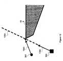
- FIG. 9illustrates some initial considerations for a tracking algorithm's risk-based strategy, according to an embodiment of the invention.
- the observer robot 303reacts by moving away from the occlusion.
- a line 901indicates the observer robot's loss of sensor contact with the target 301 based upon the target's passage into the occlusion represented by the edge of the obstacle 105 .
- the observer robot 303reacts by moving along a path 905 .
- the risk that the target 301 can escape from the observer robotcan be represented as a monotonically increasing function of the multiplicative inverse of the length of the shortest escape path (e.g., path 903 ).
- FIG. 10illustrates further movement of the target 301 towards the occlusion created by the obstacle 105 and the role of the reactive component, according to an embodiment of the invention.
- the shortest escape path for target 301is no longer path 903 but becomes path 1003 instead.
- a line 1001now represents the observer robot's loss of sensor contact with the target 301 based upon the target's passage into the occlusion created by the obstacle 105 .
- this new escape pathcan be used to determine another location for the observer robot 303 .
- FIGS. 9 and 10have described the “reactive” component of the tracking algorithm, according to an embodiment of the invention.
- Thisis the portion of the tracking algorithm that responds to the movement of the target 301 by attempting to minimize the risk associated with the shortest escape path.
- minimizing this riskis not the only factor that the tracking algorithm should consider. For instance, if the target takes a particular trajectory towards the occlusion created by the obstacle 105 , then the tracking algorithm (in the absence of a “lookahead” component) would continue to move away from the obstacle 105 so as to delay the loss of contact with the target 301 .
- the observer robot 303continues to follow the “reactive” component's trajectory, then the distance between the target 301 and the obstacle 105 will continue to grow. The increase in this distance could cause problems for the observer robot 303 in future trajectories adopted by the target 301 .
- FIG. 11illustrates the combination of the reactive component 905 and a look-ahead component 1103 and into a trajectory 1107 for the observer robot, according to an embodiment of the invention.
- FIG. 12further illustrates the role of the look-ahead component 1103 by providing an example in which the target 301 is on the same side of the obstacle 105 as the observer robot 303 .
- the target's shortest escape path 1201is toward the obstacle 105 .
- the observer robot's trajectory(for the illustrated time period) essentially amounts to a race along the observer robot's occlusion line 1203 .
- the look-ahead componentcan be represented by the square of the distance between the observer robot and the occlusion point.
- the observer robot's pathfollows neither the trajectory of the reactive component 905 nor the trajectory of the look-ahead component 1103 .
- the tracking algorithmcombines both the reactive component 905 and the look-ahead component such that the observer robot moves along the trajectory 1107 .
- cr o 2is the “look-ahead” component because its minimization increases the future ability of the observer robot to track.
- ⁇ (1/h)is the “reactive” component because its minimization decreases the likelihood that the target escapes the current visibility region. Specific embodiments of ⁇ (1/h) are log(1/h 2 +1), and (1/h) m+2 , where m is a non-negative integer.
- the gradient of the tracking equationis given by different formulas depending on the way the escape path SEP(e, q t ) exits V(q 0 ) (e.g., through a vertex of V(q 0 ) or through a corner).
- ⁇ ′(1/h)is the mathematical derivative of ⁇ (1/h) and ⁇ h is the gradient of h.
- ⁇ his calculated according to the geometry of the escape path SEP(e, q t ) associated to the edge e.
- the gradient computationcan be degenerate when the target is a single point, but it is well defined for targets with physical dimensions. Because ⁇ e is computed analytically, the track algorithm only requires current sensor information. For example, in an embodiment of the invention the function ⁇ (1/h) is equal to (1/h) 2 .
- cis a constant
- his a shortest distance between the target and the occlusion between an observer robot and the target
- r ois a distance from the observer robot to the obstacle that causes the occlusion
- ⁇is the distance from the target to said obstacle
- ais the target's radius
- ( ⁇ circumflex over (p) ⁇ , t)is a coordinate system local to the observer robot.
- the tracking strategycomprises moving the observer robot (e.g., the observer robot 303 shown in FIG. 3 ) in the opposite direction of the average of ⁇ e over all free edges e in V(q o ).
- ⁇ overscore ( ⁇ ) ⁇denote this average.
- ⁇ overscore ( ⁇ ) ⁇can be computed using the escape-path tree as explained before. However, other ways of aggregating the individual risks are possible.
- FIG. 13is a block diagram of an observer robot 1301 configured to perform the tracking algorithm, according to an embodiment of the invention.
- a CPU 1305 on the robot 1301contains instructions for carrying out the various steps of the tracking algorithm (e.g., the steps 401 - 411 shown in FIG. 4 ).
- the CPU 1305may contain software modules such as a visibility region acquisition module 1303 , a target acquisition module 1307 , an escape-path tree building module 1309 , a shortest EPT calculation module 1311 , a risk association module 1313 , a risk gradient calculation module 1321 , and a motion command calculation module 1323 .
- the visibility module 1303produces from sensor data the visibility region (e.g., the visibility region described in step 401 of FIG. 4 ) used by the tracking algorithm.
- the target acquisition module 1307performs the step (e.g., the target acquisition step 405 of FIG. 4 ) of identifying the target in the visibility region.
- the escape-path tree building module 1309constructs an EPT from the data included in the visibility region.
- the shortest EPT calculation module 1307determines the shortest escape path for the target in the EPT produced by the module 1309 .
- the risk association module 1313performs the step (e.g., the step 407 of FIG. 4 ) of associating risk with the shortest escape path determined by the module 1307 .
- the risk gradient calculation module 1321performs the step (e.g., the step 409 of FIG. 4 ) of computing the risk gradient.
- the motion command calculation module 1323uses the risk gradient calculation provided by the module 1321 to provide a motion command to the robot 1301 .
- the tracking algorithm modulesare all shown in the CPU 1305 in FIG. 13 for clarity. In actual implementation, a module (or even a portion of a module) only needs to be in the CPU 1305 at the instant in which its instructions need to be executed.
- the tracking algorithmhas been described here as comprising various software modules, the tracking algorithm could be embodied in physical hardware in a form such as an application specific integrated circuit (“ASIC”) or other suitable hardware. Accordingly, the tracking algorithm can be deployed in a variety of robotic platforms.
- ASICapplication specific integrated circuit
- the robot 1301also contains a data repository 1315 that contains a non-volatile copy of the tracking software that can be copied into the CPU 1305 as needed.
- the data repository 1315can also contain the EPT produced by the EPT module 1309 , as well as other data produced by the various modules of the tracking algorithm.
- a sensor 1319provides the raw sensor data to the visibility region acquisition module 1303 that is used to form the visibility region and that is also used by the target acquisition module 1307 to identify the target in the visibility region.
- An actuator 1317receives the motion commands provided by the command calculation module 1323 to move the robot 1301 in such a manner so as to maintain sensor contact with the target (e.g., the target 301 shown in FIG. 3 ).
- the observer robot 1301can successfully track fairly swift targets despite an abundance of data being acquired by the sensor 1319 .
- the control rate for the EPT module 1309 and the risk gradient calculation module 1321is approximately 10 Hz. Accordingly, the actuator 1317 of the robot 1301 is receiving new commands on a fairly rapid basis.
- Improvements to the tracking processingmay be achieved by embedding the tracking algorithm in a faster processor or a specialized circuit.
- the tracking processcould also be aided by improvements in the speed of the sensor 1319 , as well as the addition of other sensors (e.g., another camera) that could assist in the process of target acquisition and obstacle identification.
- the tracking problemis often interwoven with that of robot self-localization. This happens when the tracking algorithm uses a prior map of the environment to calculate the observer robot's actions. Self-localization is typically performed using landmarks. In some prior art systems, landmarks comprise artificial ceiling landmarks scattered throughout the workspace. The observer robot localizes itself with good precision if a landmark is visible. Otherwise, the observer robot navigates by dead reckoning, and the observer's position uncertainty increases until the next landmark observation.
- the tracking algorithmhas been described herein as an operation based on sensor data for a single plane.
- the tracking algorithmwould operate in a similar manner if additional planes of data were provided. For instance, this additional information could be used to more precisely identify obstacles through which the target and observer robot could not pass. Additionally, the tracking algorithm can model as obstacles objects such as holes, stairs, and poles with which the target could move either up or down.
- the following sectionprovides a more precise and detailed mathematical description of the tracking algorithm described in FIGS. 3-13 .
- a more precise statement of the problem solved by the tracking algorithmis that the observer robot (e.g., the observer robot 303 shown in FIG. 3 ) and the target (e.g., the target 301 shown in FIG. 3 ) move in a bounded Euclidean subspace W ⁇ 2 (e.g., the workspace 305 ).
- the observer robot 303 and the target 301are assumed to be rigid bodies, and their free configuration spaces are denoted C 0 and C t , respectively.
- C 0 and C tfree configuration spaces
- the Cartesian product C 0 ⁇ C tis equal to ⁇ in the absence of dynamics. In general, however, C 0 ⁇ C t is a subspace of the state space.
- the observer robot's configuration at time tis defined as q 0 (t) ⁇ C 0 and x 0 (t) as its state.
- the function ⁇ 0models the observer's dynamics and may encode non-holonomic restrictions or other constraints. For example, the function ⁇ 0 describes the observer robot's movement from 303 a to 303 b in FIG. 3 .
- q t (t) ⁇ C tbe the configuration of the target 301 at time t and x t (t) its state.
- ⁇ tdepends on x 0 (t) or q 0 (t).
- the tracking algorithm described hereinrequires no advanced knowledge of the target's movements.
- ⁇ 0for the observer robot 303
- ⁇ tfor the target 301
- the observer's configurationdetermines the field of view of its sensors (e.g., the sensor 503 shown in FIG. 5 ). More precisely, let V(q 0 ) ⁇ W be the set of all locations where the target 301 is visible to an observer robot 303 located at q 0 (e.g., q 0 is the observer's position at 303 a in FIG. 3 ).
- the set V(q 0 )is the “visibility region” at the observer's position q 0 and can be defined in several ways. For example, the observer may have a 360-degree field of view and the target may be a point in W.
- the targetis said to be visible if and only if (“iff”) the line-of-sight to the observer is un-obstructed.
- visibilitymay be limited to some fixed cone or restricted by lower and/or upper bounds on the sensor range.
- the visibility regions shown in FIG. 7comprises the shaded portion of the semi-circle that contains the target 301 .
- the tracking algorithmcan compute the visibility region from a synthetic model or from sensor measurements. In the former case, a ray-sweep algorithm can be used to compute the visibility region for conventional polygonal models. For the latter, the visibility region can be measured with a laser range-finder using conventional techniques.
- Target trackingcomprises computing a function u*(t)—a tracking strategy—such that the target 301 remains in view by the observer robot 303 for all t ⁇ [0,T] (where T is the horizon of the problem). Additionally, the tracking strategy may optimize other criteria, such as the total distance traversed by the observer robot 303 , the distance from the observer robot 303 to the target 301 , or a quality measure of the visual information. In some embodiments, losing track of the target 301 may be unavoidable, in which case an optimal tracking strategy may comprise maximizing the target's “escape time” or “time to escape” (t esc )—the time when the observer robot 303 first loses the target 301 . For example, as shown in FIG. 2 , the escape time is the instant when the target 101 rounds the obstacle 111 .
- the target 301is said to be “predictable.” In such cases, the optimal tracking strategy can typically be calculated off-line before the observer robot 303 begins to track the target 301 . Because the location of the target 301 is known for all t, the observer robot 303 may re-acquire the target 301 when it is lost. Therefore, for cases where it is impossible to track the target 301 for all t ⁇ T, an alternative is to maximize the “exposure”—the total time the target 301 is visible to the observer robot 303 —as an alternative to maximizing the escape time. For example, as shown in FIG. 2 , the exposure of the observer robot 103 to the target 101 roughly corresponds to the observer robot's positions 103 a - 103 c.
- the strategyIf the tracking strategy u*(t) is computed as a function of the state x(t), then the strategy operates in a closed loop. Otherwise, the tracking strategy runs in open loop. Closed-loop strategies are typically preferred over open-loop ones even for the predictable case, unless there is a guarantee that the target's motion models and position measurements are exact.
- FIGS. 2 and 3both illustrate the movement of unpredictable targets.
- the unpredictable casecan be analyzed in two ways. If the target actions are modeled as “non deterministic uncertainty,” then it is assumed that ⁇ is known but not a specific ⁇ (t) ⁇ . Thus, the action set is known but not the specific action selected by the target 301 at any instance. In this case, a tracking strategy can be designed that performs the best given the worst-case choices for ⁇ (t). Alternatively, if a “probabilistic uncertainty” model is available (e.g., the probability density function p( ⁇ (t)) is known), then it is possible to compute a motion plan that is the best in the expected sense.
- a “probabilistic uncertainty” modele.g., the probability density function p( ⁇ (t)) is known
- V(q 0 )is the set of all locations where the target (e.g., the target 301 shown in FIG. 3 ) is visible to an observer robot (e.g., the observer robot 303 shown in FIG. 3 ).
- V(q 0 )is represented by a list of vertices ordered counter-clockwise. The contents of this list may be split into the lists L l and L r , where L l is the list of all vertices of V(q 0 ) to the left of l(q 0 , q t ), and L r is the list of all vertices to the right of l(q 0 , q t ).
- a ray-sweep algorithmcomprises computing the shortest path from q t to the every vertex in V(q 0 ) by performing a sequential scan of L l followed by a similar scan on L r .
- Step 2Repeat until size_of ( ⁇ i ) ⁇ 3 or Step 2 fails:
- the ray-scan algorithmexploits the fact that once a vertex is no longer a member of an escape path, it will not become one again. This is a consequence of Theorem 1 discussed below.
- a path shortest escape path SEP(q t , e)is computed from a pivot list ⁇ i , at the currently visited vertex v i .
- v iThere are three mutually exclusive cases for v i and the algorithm acts differently in each case:
- each vertex in L 1 and L ris appended to the pivot list exactly once, according an embodiment of the invention. Similarly, each removed vertex is not reinserted into the list.
- the computational cost of the ray-sweep algorithmis proportional to the number of vertices stored in L 1 and L r .
- the cost for computing all the escape pathsis that O(n). This is also the cost for computing the escape-path tree, since each node in the tree is a vertex in V(q 0 ).
- the region V(q 0 ) inside a polygonal workspaceis also a polygon (in fact, the polygon is typically a star polygon).
- This visibility polygonhas linear complexity and its boundaries are composed of solid and free edges.
- a solid edgerepresents an observed section of the workspace (e.g., it is part of a physical obstacle).
- a free edge eis caused by an occlusion, and it is contained inside the workspace (e.g., it is an element of C free ⁇ W).
- An “escape path” for a target 301 located at q tis any collision-free path connecting q t to a point in W outside V(q 0 ).
- an escape path for the target 301is to place obstacle 111 , or an occlusion created by obstacle 111 , between it and the observer robot 303 .
- the “escape point” of the escape pathis the point where the path intersects the boundary of V(q 0 ), which always occurs along a free edge.
- SEP(q t , e)is called the target's “shortest escape path” through the free edge e.
- the length of SEP(q t , e)is the shortest distance to escape through e (SDE(q t , e)).
- the shortest time in which the target 301 may traverse an escape pathis the “escape time” for that path.
- the SEP(q t , e)the SEP(q t , e).
- t esc (q t , q 0 )denotes the minimum escape time along all escape paths leaving V(q 0 ) and originating in q t .
- the tracking algorithmcan compute SEP(q t , e) ⁇ e bounding V(q 0 ).
- V(q 0 )is bounded by n ⁇ free edges, there are n ⁇ “shortest” escape paths.
- the shortest SEP(q t , e) over all e bounding V(q 0 )is the shortest escape path SEP(q t , q 0 ) for the configuration (q t , q 0 ). Its length is SDE(q t , q 0 ). If the target is holonomic and has negligible inertia then SDE(q t , q 0 ) equals t esc (q t ,q 0 ) multiplied by the target's maximum speed.
- SEP(q t , e)is a polygonal line connecting q t to a point in a free edge e bounding V(q 0 ). Each vertex of this polygonal line, if any, is a vertex of V(q 0 ).
- L 1be the list of vertices of V(q 0 ) that lie to the left of l(q t , q 0 ), sorted in counter-clockwise order.
- L ras the list of vertices of V(q 0 ) to the right of l(q t , q 0 ), sorted in clockwise order. If l(q t , q 0 ) passes through a vertex of V(q 0 ), then let this vertex be included in both L 1 and L r .
- Theorem 1If the shortest path from q t to an obstacle vertex v in L 1 (or L r ) does not pass through a previous vertex u in L 1 (or L r ), then neither the shortest path from q t to any vertex w appearing after v in L 1 (or L r ) passes through u.
- Theorem 1implies that SEP(q t , e) can be constructed incrementally with a ray-sweep algorithm, such as the algorithm described above. It is only necessary to remember the shortest path from q t to the most recently visited obstacle vertex during the scanning of L 1 (or L r ).
- suitable algorithmscomprise discretizing the problem in stages of some small duration ⁇ t.
- the algorithmfinds a control action u k for the observer robot by solving the following equation: u k * ⁇ maximizing value of t esc ( q k+1 0 ( q k 0 ,u k ), q k t ) over all u k in U, where the target is assumed to remain at the same location until the next stage calculation, e.g., the acquisition of a next visibility region.
- a key to the equation aboveis the calculation of t esc . This can be a computationally expensive calculation.
- t escis upper bounded by a factor proportional to the SDE, which is a lot easier to compute.
- the following equationapproximates the equation above by solving: u k * ⁇ maximizing value of SDE ( q k+1 0 ( q k 0 ,u k ), q k t ) over all u k in U, which essentially uses the SDE as a proxy function of the escape time. In practice, this strategy typically produces poor results in all but simulated experiments and holonomic observers without dynamics. There are two problems with the equation above. One is due to the nature of the SDE function.
- cr o 2is the “look-ahead” component because its minimization increases the future ability of the observer robot to track.
- ⁇ (1/h)is the “reactive” component because its minimization decreases the likelihood that the target escapes the current visibility region.
- log(1/h 2 +1) and (1/h) m+2are examples of ⁇ (1/h).
- Observer robots employing the inventioncan autonomously monitor targets moving unpredictable in environments cluttered by obstacles.
- a robot equipped with a cameraknown as an autonomous observer (“AO”) can assist geographically distributed teams debug robotic software.
- the AOcontinuously tracks a second robot (the target) executing an independent task.
- the information acquired by the AOis supplied to remote workstations where a three-dimensional graphic rendering of the target and its environment allows the programmers to detect and correct bugs in the target's software.
- Target-tracking techniques in obstacle-laden environmentscan also be employed for the graphic animation of digital actors to select the successive viewpoints (positions of a virtual camera) under which an actor is to be displayed as it moves in its environment.
- Controllable cameras employed in surgerycould keep a patient's organ or tissue under continuous observation, despite unpredictable motions of potentially obstructing people or instruments.
- the track algorithmcan also be used to map new environments for other robots.
- the track algorithmcould be used in a robot assigned to explore new environments.
- an observer robot having the track algorithmcould be assigned to follow a target throughout an office floor, mapping the floor as it follows the target. This map could then be supplied to direct robots assigned to perform various tasks on the floor.
- the observer robotcould even be supplied with multiple sensors, such as a low-resolution sensor whose data provided the visibility regions for the observer robot's navigation and a high-resolution sensor that rendered detailed maps of the floor plan as the observer robot traversed the floor. The detailed maps could then be provided to the follow-on robots whose navigation could be controlled by other algorithms.
- the tracking algorithmmay be included in any type of mobile robot, including an anthropomorphic human robot such as the Honda ASIMO robot. Additionally, neither the sensor(s) whose data ultimately provides the visibility region, nor the track algorithm itself, necessarily needs to reside on the observer robot, provided the tracking commands can be supplied (e.g., transmitted) to the observer robot, according to an embodiment of the invention.
Landscapes
- Engineering & Computer Science (AREA)
- Radar, Positioning & Navigation (AREA)
- Aviation & Aerospace Engineering (AREA)
- Remote Sensing (AREA)
- Physics & Mathematics (AREA)
- General Physics & Mathematics (AREA)
- Automation & Control Theory (AREA)
- Control Of Position, Course, Altitude, Or Attitude Of Moving Bodies (AREA)
- Radar Systems Or Details Thereof (AREA)
Abstract
Description
φe=cro2ƒ(1/h) (The Tracking Equation),
where h=SDE(e, qt) is the shortest distance between the target and the edge e, rois the distance from the observer robot (q0) to the corner causing the occlusion at e, d is the distance between the target (qt) to this corner, c>0 is a constant and ƒ(1/h) is a monotonically increasing function of 1/h. The term cro2is the “look-ahead” component because its minimization increases the future ability of the observer robot to track. The term ƒ(1/h) is the “reactive” component because its minimization decreases the likelihood that the target escapes the current visibility region. Specific embodiments of ƒ(1/h) are log(1/h2+1), and (1/h)m+2, where m is a non-negative integer.
−∇φe=2croƒ(1/h)+c(ro/h)2ƒ′(1/h)∇h.
Here, ƒ′(1/h) is the mathematical derivative of ƒ(1/h) and ∇h is the gradient of h. ∇h is calculated according to the geometry of the escape path SEP(e, qt) associated to the edge e. The gradient computation can be degenerate when the target is a single point, but it is well defined for targets with physical dimensions. Because ∇φeis computed analytically, the track algorithm only requires current sensor information. For example, in an embodiment of the invention the function ƒ(1/h) is equal to (1/h)2. For the scenario shown in
−∇φe=−2cro(1/h)2{circumflex over (p)}+2cδro(1/h)3t,
and for the scenario shown in
−∇φe=−2cro(1/h)2{circumflex over (p)}+2cσro(1/h)3t.
Here c is a constant, h is a shortest distance between the target and the occlusion between an observer robot and the target, rois a distance from the observer robot to the obstacle that causes the occlusion, δ is the distance from the target to said obstacle, a is the target's radius, and ({circumflex over (p)}, t) is a coordinate system local to the observer robot.
uk*←maximizing value oftesc(qk+10(qk0,uk),qkt) over allukinU,
where the target is assumed to remain at the same location until the next stage calculation, e.g., the acquisition of a next visibility region. A key to the equation above is the calculation of tesc. This can be a computationally expensive calculation.
uk*←maximizing value ofSDE(qk+10(qk0,uk),qkt) over allukinU,
which essentially uses the SDE as a proxy function of the escape time. In practice, this strategy typically produces poor results in all but simulated experiments and holonomic observers without dynamics. There are two problems with the equation above. One is due to the nature of the SDE function. As the observer robot moves, new occlusions form and old ones disappear, and new escape paths become the shortest escape path. As a result, the value of uk* can change abruptly from one state to the next producing a shattering effect on the control signal. Un-modeled observer robot dynamics will be excited by a shattering signal, producing very erratic and unpredictable motions in the observer robot. The second problem is that the SDE is not a good proxy function for tesc. The relationship between SDE and tescis not linear. In fact, a large SDE makes it increasingly harder for the target to escape. To understand this, imagine a situation where the SDE becomes increasingly larger. Tracking becomes easier not only because the target has to travel a longer distance in order to escape, but also because the observer robot has time to improve its ability to track the target in the future. Both problems associated with the second equation above can be solved by using the following proxy function for tesc. This function is the “escape risk,” defined for every free edge e as follows:
φe=cro2ƒ(1/h),
where h=SDE(e, qt) is the shortest distance between the target and the edge e, rois the distance from the observer robot (q0) to the corner causing the occlusion at e, d is the distance between the target (qt) to said corner, c>0 is a constant and ƒ(1/h) is a monotonically increasing function of 1/h. The term cro2is the “look-ahead” component because its minimization increases the future ability of the observer robot to track. The term ƒ(1/h) is the “reactive” component because its minimization decreases the likelihood that the target escapes the current visibility region. The functions log(1/h2+1) and (1/h)m+2(for a non-negative integer m) are examples of ƒ(1/h).
Applications of the Tracking Algorithm
Claims (27)
φe=cro2ƒ(1/h),
φe=cro2ƒ(1/h),
−∇φe=2croƒ(1/h)+c(ro/h)2ƒ′(1/h)∇h,
−∇φe=2croƒ′(1/h)+c(ro/h)2ƒ′(1/h)∇h,
Priority Applications (1)
| Application Number | Priority Date | Filing Date | Title |
|---|---|---|---|
| US10/435,934US6917855B2 (en) | 2002-05-10 | 2003-05-12 | Real-time target tracking of an unpredictable target amid unknown obstacles |
Applications Claiming Priority (2)
| Application Number | Priority Date | Filing Date | Title |
|---|---|---|---|
| US37801502P | 2002-05-10 | 2002-05-10 | |
| US10/435,934US6917855B2 (en) | 2002-05-10 | 2003-05-12 | Real-time target tracking of an unpredictable target amid unknown obstacles |
Publications (2)
| Publication Number | Publication Date |
|---|---|
| US20040073368A1 US20040073368A1 (en) | 2004-04-15 |
| US6917855B2true US6917855B2 (en) | 2005-07-12 |
Family
ID=29420361
Family Applications (1)
| Application Number | Title | Priority Date | Filing Date |
|---|---|---|---|
| US10/435,934Expired - LifetimeUS6917855B2 (en) | 2002-05-10 | 2003-05-12 | Real-time target tracking of an unpredictable target amid unknown obstacles |
Country Status (5)
| Country | Link |
|---|---|
| US (1) | US6917855B2 (en) |
| EP (1) | EP1504277B1 (en) |
| JP (1) | JP3875988B2 (en) |
| AU (1) | AU2003229008A1 (en) |
| WO (1) | WO2003096054A2 (en) |
Cited By (41)
| Publication number | Priority date | Publication date | Assignee | Title |
|---|---|---|---|---|
| US20040167669A1 (en)* | 2002-12-17 | 2004-08-26 | Karlsson L. Niklas | Systems and methods for using multiple hypotheses in a visual simultaneous localization and mapping system |
| US20040230340A1 (en)* | 2003-03-28 | 2004-11-18 | Masaki Fukuchi | Behavior controlling apparatus, behavior control method, behavior control program and mobile robot apparatus |
| US20040249504A1 (en)* | 2001-11-30 | 2004-12-09 | Steffen Gutmann | Robot self-position identification system and self-position identification method |
| US20050182518A1 (en)* | 2004-02-13 | 2005-08-18 | Evolution Robotics, Inc. | Robust sensor fusion for mapping and localization in a simultaneous localization and mapping (SLAM) system |
| US20060031015A1 (en)* | 2004-08-09 | 2006-02-09 | M/A-Com, Inc. | Imminent-collision detection system and process |
| US20060095170A1 (en)* | 2004-11-03 | 2006-05-04 | Samsung Electronics Co., Ltd. | System and method for identifying objects in a space |
| US20060106496A1 (en)* | 2004-11-18 | 2006-05-18 | Tamao Okamoto | Method of controlling movement of mobile robot |
| US20060108960A1 (en)* | 2002-07-18 | 2006-05-25 | Michiharu Tanaka | Robot controller and robot system |
| US20060149489A1 (en)* | 2004-04-16 | 2006-07-06 | Frank Joublin | Self-calibrating sensor orienting system |
| US20060177101A1 (en)* | 2005-02-10 | 2006-08-10 | Hitachi, Ltd. | Self-locating device and program for executing self-locating method |
| US20060293792A1 (en)* | 2005-06-17 | 2006-12-28 | Honda Motor Co., Ltd. | Path generator for mobile object |
| US20060293790A1 (en)* | 2005-05-31 | 2006-12-28 | Michael Gienger | Controlling the trajectory of an effector |
| US20070038398A1 (en)* | 2005-08-10 | 2007-02-15 | Frank Joublin | Increasing robustness of online calibration through motion detection |
| US20070100498A1 (en)* | 2005-10-27 | 2007-05-03 | Kosei Matsumoto | Mobile robot |
| US20070199108A1 (en)* | 2005-09-30 | 2007-08-23 | Colin Angle | Companion robot for personal interaction |
| US20080079383A1 (en)* | 2006-09-28 | 2008-04-03 | Kabushiki Kaisha Toshiba | Method of controlling movement of robot, mobile robot, and computer program product |
| US20080269017A1 (en)* | 2007-04-30 | 2008-10-30 | Nike, Inc. | Adaptive Training System |
| US20080306628A1 (en)* | 2007-06-08 | 2008-12-11 | Honda Motor Co., Ltd. | Multi-Modal Push Planner for Humanoid Robots |
| US20090012667A1 (en)* | 2007-07-04 | 2009-01-08 | Kosei Matsumoto | Mobile device, moving system, moving method, and moving program |
| US7509177B2 (en) | 2004-04-16 | 2009-03-24 | Honda Research Institute Europe Gmbh | Self-calibrating orienting system for a manipulating device |
| US20090254235A1 (en)* | 2008-04-03 | 2009-10-08 | Honda Motor Co., Ltd. | Object recognition system for autonomous mobile body |
| US20100036556A1 (en)* | 2006-09-28 | 2010-02-11 | Sang-Ik Na | Autonomous mobile robot capable of detouring obstacle and method thereof |
| US20100063627A1 (en)* | 2007-06-15 | 2010-03-11 | Toyota Jidosha Kabushiki Kaisha | Autonomous mobile apparatus and method of mobility |
| US20100117889A1 (en)* | 2008-11-10 | 2010-05-13 | The Boeing Company | System and method for detecting performance of a sensor field at all points within a geographic area of regard |
| US20100174435A1 (en)* | 2009-01-07 | 2010-07-08 | Samsung Electronics Co., Ltd. | Path planning apparatus of robot and method thereof |
| US8260485B1 (en)* | 2007-04-26 | 2012-09-04 | The Boeing Company | Adaptive multi-vehicle area coverage optimization system and method |
| US8525836B1 (en)* | 2012-02-07 | 2013-09-03 | Google Inc. | Systems and methods for representing information associated with objects in an area |
| US8798840B2 (en) | 2011-09-30 | 2014-08-05 | Irobot Corporation | Adaptive mapping with spatial summaries of sensor data |
| US9020637B2 (en) | 2012-11-02 | 2015-04-28 | Irobot Corporation | Simultaneous localization and mapping for a mobile robot |
| US9037396B2 (en) | 2013-05-23 | 2015-05-19 | Irobot Corporation | Simultaneous localization and mapping for a mobile robot |
| US9286810B2 (en) | 2010-09-24 | 2016-03-15 | Irobot Corporation | Systems and methods for VSLAM optimization |
| US9321173B2 (en) | 2012-06-22 | 2016-04-26 | Microsoft Technology Licensing, Llc | Tracking and following people with a mobile robotic device |
| WO2016126297A3 (en)* | 2014-12-24 | 2016-11-03 | Irobot Corporation | Mobile security robot |
| US10100968B1 (en) | 2017-06-12 | 2018-10-16 | Irobot Corporation | Mast systems for autonomous mobile robots |
| US10471611B2 (en) | 2016-01-15 | 2019-11-12 | Irobot Corporation | Autonomous monitoring robot systems |
| US11110595B2 (en) | 2018-12-11 | 2021-09-07 | Irobot Corporation | Mast systems for autonomous mobile robots |
| US11325252B2 (en)* | 2018-09-15 | 2022-05-10 | X Development Llc | Action prediction networks for robotic grasping |
| US11417105B1 (en) | 2021-02-16 | 2022-08-16 | Motorola Solutions, Inc. | Identifying individuals who witnessed a fleeing suspect |
| US11498587B1 (en)* | 2019-01-25 | 2022-11-15 | Amazon Technologies, Inc. | Autonomous machine motion planning in a dynamic environment |
| US20240109177A1 (en)* | 2022-10-01 | 2024-04-04 | Tianqi (George) Sun | Small intelligent robot system |
| US12443181B2 (en) | 2023-04-26 | 2025-10-14 | Irobot Corporation | Autonomous monitoring robot systems |
Families Citing this family (47)
| Publication number | Priority date | Publication date | Assignee | Title |
|---|---|---|---|---|
| EP1504277B1 (en) | 2002-05-10 | 2012-10-10 | Honda Giken Kogyo Kabushiki Kaisha | Real-time target tracking of an unpredictable target amid unknown obstacles |
| US7908040B2 (en)* | 2004-07-15 | 2011-03-15 | Raytheon Company | System and method for automated search by distributed elements |
| US8000837B2 (en) | 2004-10-05 | 2011-08-16 | J&L Group International, Llc | Programmable load forming system, components thereof, and methods of use |
| US20060235610A1 (en)* | 2005-04-14 | 2006-10-19 | Honeywell International Inc. | Map-based trajectory generation |
| US7533073B2 (en) | 2005-12-05 | 2009-05-12 | Raytheon Company | Methods and apparatus for heuristic search to optimize metrics in generating a plan having a series of actions |
| JP4699426B2 (en)* | 2006-08-08 | 2011-06-08 | パナソニック株式会社 | Obstacle avoidance method and obstacle avoidance moving device |
| JP2008191781A (en)* | 2007-02-01 | 2008-08-21 | Hitachi Ltd | Collision avoidance system |
| JP5159369B2 (en)* | 2008-02-29 | 2013-03-06 | 三菱電機株式会社 | Search and monitoring method with multiple robots |
| EP2107504A1 (en)* | 2008-03-31 | 2009-10-07 | Harman Becker Automotive Systems GmbH | Method and device for generating a real time environment model for vehicles |
| JP5160322B2 (en)* | 2008-06-30 | 2013-03-13 | 株式会社Ihi | Autonomous mobile robot apparatus and control method for autonomous mobile robot apparatus |
| MX2011006855A (en)* | 2008-12-23 | 2012-01-25 | Evan Baumgarten | Chasing training device. |
| US20110161060A1 (en)* | 2009-12-29 | 2011-06-30 | Changkyu Kim | Optimization-Based exact formulation and solution of crowd simulation in virtual worlds |
| US20120150573A1 (en)* | 2010-12-13 | 2012-06-14 | Omar Soubra | Real-time site monitoring design |
| US20130197736A1 (en)* | 2012-01-30 | 2013-08-01 | Google Inc. | Vehicle control based on perception uncertainty |
| US9760092B2 (en) | 2012-03-16 | 2017-09-12 | Waymo Llc | Actively modifying a field of view of an autonomous vehicle in view of constraints |
| KR20140137893A (en)* | 2013-05-24 | 2014-12-03 | 한국전자통신연구원 | Method and appratus for tracking object |
| US10963133B2 (en) | 2014-01-07 | 2021-03-30 | Honeywell International Inc. | Enhanced awareness of obstacle proximity |
| US10431105B2 (en)* | 2014-01-07 | 2019-10-01 | Honeywell International Inc. | Enhanced awareness of obstacle proximity |
| CN104317299B (en)* | 2014-11-11 | 2017-01-25 | 东南大学 | Mixed control method based on trace tracking of wheeled mobile robot |
| CN104932506B (en)* | 2015-06-09 | 2017-09-19 | 东南大学 | Trajectory Tracking Method for Wheeled Mobile Robot Based on Fast Terminal Sliding Mode |
| JP6680498B2 (en)* | 2015-09-28 | 2020-04-15 | 株式会社日立システムズ | Autonomous flying vehicle, target tracking method |
| US9744665B1 (en)* | 2016-01-27 | 2017-08-29 | X Development Llc | Optimization of observer robot locations |
| EP3568842B1 (en) | 2017-01-10 | 2022-06-29 | Alarm.com Incorporated | Emergency drone guidance device |
| WO2018136510A1 (en)* | 2017-01-17 | 2018-07-26 | Babak Rezvani | Dynamic drone navigation |
| US10754351B2 (en)* | 2017-02-28 | 2020-08-25 | Toyota Jidosha Kabushiki Kaisha | Observability grid-based autonomous environment search |
| US10816974B2 (en) | 2017-02-28 | 2020-10-27 | Toyota Jidosha Kabushiki Kaisha | Proactive acquisition of data for maintenance of appearance model by mobile robot |
| JP7017025B2 (en)* | 2017-03-08 | 2022-02-08 | 日本電気株式会社 | Autonomous mobile robots, control methods and control programs for autonomous mobile robots |
| CN110462546A (en)* | 2017-03-28 | 2019-11-15 | 日本电产株式会社 | Moving body |
| US11856938B1 (en) | 2017-03-31 | 2024-01-02 | Alarm.Com Incorporated | Robotic rover |
| JP6825715B2 (en)* | 2017-10-06 | 2021-02-03 | 株式会社豊田自動織機 | Mobile vehicle |
| CN108037767A (en)* | 2017-12-13 | 2018-05-15 | 王俊梅 | A kind of unmanned plane visual dead angles turn to escape flight system |
| US12019452B2 (en)* | 2018-03-26 | 2024-06-25 | Jabil Inc | Apparatus, system, and method of using depth assessment for autonomous robot navigation |
| JP6988637B2 (en)* | 2018-03-28 | 2022-01-05 | トヨタ自動車株式会社 | Automatic driving course determination device |
| EP3823795A4 (en)* | 2018-07-16 | 2022-04-06 | Brain Corporation | SYSTEMS AND METHODS FOR OPTIMIZING ROUTE PLANNING FOR TIGHT TURNS FOR ROBOTIC APPLIANCES |
| CN109085836A (en)* | 2018-08-29 | 2018-12-25 | 深圳市浦硕科技有限公司 | A kind of method that sweeping robot returns designated position minimal path |
| KR102749960B1 (en)* | 2018-12-26 | 2025-01-03 | 삼성전자주식회사 | Cleaning robot and Method of performing task thereof |
| CN111714028A (en)* | 2019-03-18 | 2020-09-29 | 北京奇虎科技有限公司 | Method, device, device and readable storage medium for getting out of restricted area of cleaning equipment |
| CN110103237A (en)* | 2019-05-13 | 2019-08-09 | 湖北经济学院 | The follower type robot Fellow of view-based access control model target following |
| CN112748720A (en)* | 2019-10-29 | 2021-05-04 | 北京百度网讯科技有限公司 | Control method, device, equipment and storage medium for automatic driving vehicle |
| CN112824832B (en)* | 2019-11-20 | 2024-07-19 | 炬星科技(深圳)有限公司 | Obstacle movement track prediction method, system, equipment and computer readable storage medium |
| US11438886B2 (en)* | 2020-02-27 | 2022-09-06 | Psj International Ltd. | System for establishing positioning map data and method for the same |
| WO2021246170A1 (en)* | 2020-06-03 | 2021-12-09 | ソニーグループ株式会社 | Information processing device, information processing system and method, and program |
| CN112965490B (en)* | 2021-02-07 | 2024-07-19 | 京东科技信息技术有限公司 | Method and device for controlling robot and non-transitory computer readable storage medium |
| CN114049602B (en)* | 2021-10-29 | 2022-06-14 | 哈尔滨工业大学 | A method and system for evasive target tracking based on intent reasoning |
| CN114518754B (en)* | 2022-01-28 | 2024-04-23 | 西北工业大学 | Multi-agent escape problem modeling and trapping strategy generation method |
| CN115008465B (en)* | 2022-06-29 | 2025-08-26 | 武汉擎朗智能科技有限公司 | Robot control method, robot, and computer-readable storage medium |
| CN118484000B (en)* | 2024-05-07 | 2025-01-17 | 浙江神州明月智能科技有限公司 | Robot autonomous navigation obstacle avoidance system and method based on multi-sensor fusion |
Citations (13)
| Publication number | Priority date | Publication date | Assignee | Title |
|---|---|---|---|---|
| US4627511A (en)* | 1984-10-18 | 1986-12-09 | Casio Computer Co., Ltd. | Optical tracking robot system |
| US4747458A (en) | 1984-06-27 | 1988-05-31 | Commissariat A L'energie Atomique | Process for the control of active moving body relative to a local passive environment with the aid of local proximetric transducers |
| US4761595A (en)* | 1987-05-01 | 1988-08-02 | General Motors Corporation | Motion control system having adaptive feedforward path tracking |
| US4980626A (en)* | 1989-08-10 | 1990-12-25 | The United States Of America As Represented By The Administrator Of The National Aeronautics And Space Administration | Method and apparatus for positioning a robotic end effector |
| US5006999A (en)* | 1988-04-01 | 1991-04-09 | Toyota Jidosha Kabushiki Kaisha | Real-time robot control system tracking based on a standard path |
| US5416713A (en)* | 1992-10-30 | 1995-05-16 | Mitsubishi Denki Kabushiki Kaisha | Obstacle avoidance apparatus |
| US5506682A (en)* | 1982-02-16 | 1996-04-09 | Sensor Adaptive Machines Inc. | Robot vision using targets |
| US5999881A (en)* | 1997-05-05 | 1999-12-07 | General Electric Company | Automated path planning |
| US6201231B1 (en)* | 1997-10-02 | 2001-03-13 | Diehl Stiftung & Co. | Testing system for measuring and optimising target tracking systems |
| US20020022927A1 (en) | 1993-08-11 | 2002-02-21 | Lemelson Jerome H. | GPS vehicle collision avoidance warning and control system and method |
| US6442476B1 (en)* | 1998-04-15 | 2002-08-27 | Research Organisation | Method of tracking and sensing position of objects |
| US6463356B1 (en)* | 1999-11-24 | 2002-10-08 | Sony Corporation | Legged mobile robot and method of controlling operation of the same |
| WO2003096054A2 (en) | 2002-05-10 | 2003-11-20 | Honda Giken Kogyo Kabushiki Kaisha | Real-time target tracking of an unpredictable target amid unknown obstacles |
Family Cites Families (4)
| Publication number | Priority date | Publication date | Assignee | Title |
|---|---|---|---|---|
| US4023178A (en) | 1974-07-24 | 1977-05-10 | Sanyo Electric Co., Ltd. | Radio-controlled vehicle with RF noise elimination feature and with ultrasonic anti-collision means insensitive to mechanical shocks |
| US4747758A (en)* | 1986-04-17 | 1988-05-31 | Saurwein Albert C | Fluid pressure-intensifier |
| DE4326016C1 (en)* | 1993-08-03 | 1994-09-15 | Bail Guenther | Self-propelled vehicle, preferably golf trolley |
| DE19509320A1 (en) | 1995-03-15 | 1996-09-19 | Technologietransfer Anstalt Te | Sequence control for a self-driving vehicle |
- 2003
- 2003-05-12EPEP03726788Apatent/EP1504277B1/ennot_activeExpired - Lifetime
- 2003-05-12WOPCT/US2003/014809patent/WO2003096054A2/enactiveApplication Filing
- 2003-05-12USUS10/435,934patent/US6917855B2/ennot_activeExpired - Lifetime
- 2003-05-12AUAU2003229008Apatent/AU2003229008A1/ennot_activeAbandoned
- 2003-05-12JPJP2005518132Apatent/JP3875988B2/ennot_activeExpired - Fee Related
Patent Citations (13)
| Publication number | Priority date | Publication date | Assignee | Title |
|---|---|---|---|---|
| US5506682A (en)* | 1982-02-16 | 1996-04-09 | Sensor Adaptive Machines Inc. | Robot vision using targets |
| US4747458A (en) | 1984-06-27 | 1988-05-31 | Commissariat A L'energie Atomique | Process for the control of active moving body relative to a local passive environment with the aid of local proximetric transducers |
| US4627511A (en)* | 1984-10-18 | 1986-12-09 | Casio Computer Co., Ltd. | Optical tracking robot system |
| US4761595A (en)* | 1987-05-01 | 1988-08-02 | General Motors Corporation | Motion control system having adaptive feedforward path tracking |
| US5006999A (en)* | 1988-04-01 | 1991-04-09 | Toyota Jidosha Kabushiki Kaisha | Real-time robot control system tracking based on a standard path |
| US4980626A (en)* | 1989-08-10 | 1990-12-25 | The United States Of America As Represented By The Administrator Of The National Aeronautics And Space Administration | Method and apparatus for positioning a robotic end effector |
| US5416713A (en)* | 1992-10-30 | 1995-05-16 | Mitsubishi Denki Kabushiki Kaisha | Obstacle avoidance apparatus |
| US20020022927A1 (en) | 1993-08-11 | 2002-02-21 | Lemelson Jerome H. | GPS vehicle collision avoidance warning and control system and method |
| US5999881A (en)* | 1997-05-05 | 1999-12-07 | General Electric Company | Automated path planning |
| US6201231B1 (en)* | 1997-10-02 | 2001-03-13 | Diehl Stiftung & Co. | Testing system for measuring and optimising target tracking systems |
| US6442476B1 (en)* | 1998-04-15 | 2002-08-27 | Research Organisation | Method of tracking and sensing position of objects |
| US6463356B1 (en)* | 1999-11-24 | 2002-10-08 | Sony Corporation | Legged mobile robot and method of controlling operation of the same |
| WO2003096054A2 (en) | 2002-05-10 | 2003-11-20 | Honda Giken Kogyo Kabushiki Kaisha | Real-time target tracking of an unpredictable target amid unknown obstacles |
Non-Patent Citations (23)
| Title |
|---|
| C. B. Congdon et al., "CARMEL vs. Flakey: A Comparison of Two Robots," Internet, Draft Jan. 1994, pp. 1-52. |
| C. Becker et al., "An Intelligent Observer," in Proc 4<SUP>th </SUP>International Symposium on Experimental Robotics, 1995, Springer, pp. 153-160. |
| D. P. Huttenlocher et al., "Tracking Non-Rigid Objects in Complex Scenes," IEEE, Proc. 4<SUP>th </SUP>Int. Conf. on Computer Vision, 1993, pp. 93-101. |
| H. Choset, "Topological Simultaneous Localization and Mapping (SLAM): Toward Exact Localization Without Explicit Localization," IEEE, 2001, pp. 125-137. |
| H. González-Banos and J.C. Latombe, "Robot Navigation for Automatic Model Construction Using Safe Regions," Lecture Notes in Control and Information Sciences, 271, D. Russ and S. Singh, Eds. 2001, pp. 405-415. |
| H. González-Banos et al., "Planning Robot Motion Strategies for Efficient Model Construction," Robotics Research-the Ninth Int. Symp., J. Hollerbach and D. Koditschek, Eds., Salt Lake City, UT, 1999, Springer-Berlag, pp. 345-352. |
| H. González-Banos et al., "The Autonomous Observer: A Tool for Remote Experimentation in Robotics," Telemanipulator and Telepresence Technologies VI, Matthew Stein, Ed., Sep. 1999, vol. 3840, SPIE Proc., pp. 210-221. |
| H. González-Banos, "Motion Strategies for Autonomous Observers," Ph.D. Thesis, Stanford University, Mar. 2001. |
| H. Li et al., "An Embedded System for Autonomous Collision Avoidance and Line Tracking Using Artificial CMOS Retina Sensor," IEEE, Intelligent Vehicles Sumposium, 2000, pp. 279-283. |
| I. Ishiguro et al., "Robovie: A Robot Generates Episode Chains in our Daily Life," Proc. Of the 32<SUP>nd </SUP>International Symp. Of Robotics, Apr. 2001, 6 pp. |
| L. J. Guibas et al., "A Visibility-Based Pursuit-Evasion Problem," Int. J. of Computational Geometry and Applications, vol. 9, Nos. 4&5, 1999, pp. 471-493. |
| Mehlhorn, K., Naher, S., Leda: A Platform of Combinatorial and Geometric Computing, 1999, pp. 637-656, Cambridge University Press, Cambridge UK. |
| N. P. Papanikolopoulos et al., "Visual Tracking of a Moving Target by a Camera Mounted on a Robot: A Combination of Control and Vision," IEEE Trans. On Robotics and Automation, vol. 9, No. 1, Feb. 1993, pp. 14-35. |
| O'Rourke, J., "Visibility," Handbook of Discrete and Computational, Geometry, 1997, pp. 467-479, CRC Press, Boca Raton, FL, USA. |
| P. Fabiani and J.C. Latombe, Dealing with Geometric Constraints in Game-Theoretic Planning, in Proc Int. Joint Conf. On Artif. Intell., 1999, pp. 942-947. |
| P. Fabiani et al., "Tracking a Partially Predictable Target with Uncertainties and Visibility Constraints," Preprint submitted to Elsevier Preprint, Nov. 15, 2000, pp. 1-24. |
| P. Ögren and N. Leonard, "A Provably Convergent Dynamic Window Approach Obstacle Avoidance," Internet, 2001, pp. 1-6. |
| S. Hutchinson et al., "A Tutorial on Visual Servo Control," IEEE Trans. Robotics and Automation, vol. 12, No. 5, Oct. 1996, pp. 651-670. |
| S. M. LaValle et al., "Motion Strategies for Maintaining Visibility of Moving Target," Proc. 1997 IEEE Int'l. Conf. On Robotics and Automation, Apr. 1997, pp. 731-736. |
| S. M. LaValle, "A Game-Theoretic Framework for Robot Motion Planning," Ph. D. Thesis, University of Illinois, Urbana, IL, Jul. 1995. |
| Slotine, J.J.-E., Li, Weiping, Applied Linear Control, 1991, pp. 283-284, Prentice-Hall, Inc., Englewood Cliffs, NJ, USA. |
| T. Shermer, "Recent Results in Art Galleries," Proc. IEEE, vol. 80, No. 9, Sep. 1992, pp. 1384-1399. |
| T. Y. Li et al., "Automatically Generating Virtual Guided Tours," Proc. Of the 1999 Computer Animation Conference, May 1999, pp. 99-106. |
Cited By (101)
| Publication number | Priority date | Publication date | Assignee | Title |
|---|---|---|---|---|
| US20040249504A1 (en)* | 2001-11-30 | 2004-12-09 | Steffen Gutmann | Robot self-position identification system and self-position identification method |
| US7263412B2 (en)* | 2001-11-30 | 2007-08-28 | Sony Corporation | Robot self-position identification system and self-position identification method |
| US7391178B2 (en)* | 2002-07-18 | 2008-06-24 | Kabushiki Kaisha Yaskawa Denki | Robot controller and robot system |
| US20060108960A1 (en)* | 2002-07-18 | 2006-05-25 | Michiharu Tanaka | Robot controller and robot system |
| US8274406B2 (en) | 2002-12-17 | 2012-09-25 | Evolution Robotics, Inc. | Systems and methods for using multiple hypotheses in a visual simultaneous localization and mapping system |
| US8508388B2 (en) | 2002-12-17 | 2013-08-13 | Irobot Corporation | Systems and methods for using multiple hypotheses in a visual simultaneous localization and mapping system |
| US20100268697A1 (en)* | 2002-12-17 | 2010-10-21 | Evolution Robotics, Inc. | Systems and methods for using multiple hypotheses in a visual simultaneous localization and mapping system |
| US20040167688A1 (en)* | 2002-12-17 | 2004-08-26 | Karlsson L. Niklas | Systems and methods for correction of drift via global localization with a visual landmark |
| US20100286905A1 (en)* | 2002-12-17 | 2010-11-11 | Evolution Robotics, Inc. | Systems and methods for filtering potentially unreliable visual data for visual simultaneous localization and mapping |
| US20060012493A1 (en)* | 2002-12-17 | 2006-01-19 | Karlsson L N | Systems and methods for incrementally updating a pose of a mobile device calculated by visual simultaneous localization and mapping techniques |
| US20100284621A1 (en)* | 2002-12-17 | 2010-11-11 | Evolution Robotics, Inc. | Systems and methods for adding a landmarks for visual simultaneous localization and mapping |
| US7015831B2 (en)* | 2002-12-17 | 2006-03-21 | Evolution Robotics, Inc. | Systems and methods for incrementally updating a pose of a mobile device calculated by visual simultaneous localization and mapping techniques |
| US8086419B2 (en) | 2002-12-17 | 2011-12-27 | Evolution Robotics, Inc. | Systems and methods for adding landmarks for visual simultaneous localization and mapping |
| US8095336B2 (en) | 2002-12-17 | 2012-01-10 | Evolution Robotics, Inc. | Systems and methods for determining whether to add a landmark for visual simultaneous localization and mapping |
| US20040167670A1 (en)* | 2002-12-17 | 2004-08-26 | Goncalves Luis Filipe Domingues | Systems and methods for computing a relative pose for global localization in a visual simultaneous localization and mapping system |
| US8150650B2 (en) | 2002-12-17 | 2012-04-03 | Evolution Robotics, Inc. | Systems and methods for filtering potentially unreliable visual data for visual simultaneous localization and mapping |
| US7774158B2 (en) | 2002-12-17 | 2010-08-10 | Evolution Robotics, Inc. | Systems and methods for landmark generation for visual simultaneous localization and mapping |
| US7135992B2 (en)* | 2002-12-17 | 2006-11-14 | Evolution Robotics, Inc. | Systems and methods for using multiple hypotheses in a visual simultaneous localization and mapping system |
| US7145478B2 (en) | 2002-12-17 | 2006-12-05 | Evolution Robotics, Inc. | Systems and methods for controlling a density of visual landmarks in a visual simultaneous localization and mapping system |
| US9886037B2 (en) | 2002-12-17 | 2018-02-06 | Irobot Corporation | Systems and methods for using multiple hypotheses in a visual simultaneous localization and mapping system |
| US8830091B2 (en) | 2002-12-17 | 2014-09-09 | Irobot Corporation | Systems and methods for using multiple hypotheses in a visual simultaneous localization and mapping system |
| US7162338B2 (en) | 2002-12-17 | 2007-01-09 | Evolution Robotics, Inc. | Systems and methods for computing a relative pose for global localization in a visual simultaneous localization and mapping system |
| US7177737B2 (en) | 2002-12-17 | 2007-02-13 | Evolution Robotics, Inc. | Systems and methods for correction of drift via global localization with a visual landmark |
| US20040167716A1 (en)* | 2002-12-17 | 2004-08-26 | Goncalves Luis Filipe Domingues | Systems and methods for controlling a density of visual landmarks in a visual simultaneous localization and mapping system |
| US20040168148A1 (en)* | 2002-12-17 | 2004-08-26 | Goncalves Luis Filipe Domingues | Systems and methods for landmark generation for visual simultaneous localization and mapping |
| US20040167667A1 (en)* | 2002-12-17 | 2004-08-26 | Goncalves Luis Filipe Domingues | Systems and methods for filtering potentially unreliable visual data for visual simultaneous localization and mapping |
| US20040167669A1 (en)* | 2002-12-17 | 2004-08-26 | Karlsson L. Niklas | Systems and methods for using multiple hypotheses in a visual simultaneous localization and mapping system |
| US7272467B2 (en) | 2002-12-17 | 2007-09-18 | Evolution Robotics, Inc. | Systems and methods for filtering potentially unreliable visual data for visual simultaneous localization and mapping |
| US9110470B2 (en) | 2002-12-17 | 2015-08-18 | Irobot Corporation | Systems and methods for using multiple hypotheses in a visual simultaneous localization and mapping system |
| US20040230340A1 (en)* | 2003-03-28 | 2004-11-18 | Masaki Fukuchi | Behavior controlling apparatus, behavior control method, behavior control program and mobile robot apparatus |
| US7689321B2 (en)* | 2004-02-13 | 2010-03-30 | Evolution Robotics, Inc. | Robust sensor fusion for mapping and localization in a simultaneous localization and mapping (SLAM) system |
| US20050182518A1 (en)* | 2004-02-13 | 2005-08-18 | Evolution Robotics, Inc. | Robust sensor fusion for mapping and localization in a simultaneous localization and mapping (SLAM) system |
| US7509177B2 (en) | 2004-04-16 | 2009-03-24 | Honda Research Institute Europe Gmbh | Self-calibrating orienting system for a manipulating device |
| US7324907B2 (en)* | 2004-04-16 | 2008-01-29 | Honda Research Institute Europe Gmbh | Self-calibrating sensor orienting system |
| US20060149489A1 (en)* | 2004-04-16 | 2006-07-06 | Frank Joublin | Self-calibrating sensor orienting system |
| US7409295B2 (en)* | 2004-08-09 | 2008-08-05 | M/A-Com, Inc. | Imminent-collision detection system and process |
| US20060031015A1 (en)* | 2004-08-09 | 2006-02-09 | M/A-Com, Inc. | Imminent-collision detection system and process |
| US7539563B2 (en)* | 2004-11-03 | 2009-05-26 | Samsung Electronics Co., Ltd. | System and method for identifying objects in a space |
| US20060095170A1 (en)* | 2004-11-03 | 2006-05-04 | Samsung Electronics Co., Ltd. | System and method for identifying objects in a space |
| US20060106496A1 (en)* | 2004-11-18 | 2006-05-18 | Tamao Okamoto | Method of controlling movement of mobile robot |
| US7818090B2 (en)* | 2004-11-18 | 2010-10-19 | Panasonic Corporation | Method of controlling movement of mobile robot |
| US20060177101A1 (en)* | 2005-02-10 | 2006-08-10 | Hitachi, Ltd. | Self-locating device and program for executing self-locating method |
| US8509951B2 (en) | 2005-05-31 | 2013-08-13 | Honda Research Institute Europe Gmbh | Controlling the trajectory of an effector |
| US20060293790A1 (en)* | 2005-05-31 | 2006-12-28 | Michael Gienger | Controlling the trajectory of an effector |
| US7519457B2 (en)* | 2005-06-17 | 2009-04-14 | Honda Motor Company, Ltd. | Path generator for mobile object |
| US20060293792A1 (en)* | 2005-06-17 | 2006-12-28 | Honda Motor Co., Ltd. | Path generator for mobile object |
| US20070038398A1 (en)* | 2005-08-10 | 2007-02-15 | Frank Joublin | Increasing robustness of online calibration through motion detection |
| US7295942B2 (en) | 2005-08-10 | 2007-11-13 | Honda Research Institute Europe Gmbh | Increasing robustness of online calibration through motion detection |
| US20070199108A1 (en)* | 2005-09-30 | 2007-08-23 | Colin Angle | Companion robot for personal interaction |
| US9878445B2 (en) | 2005-09-30 | 2018-01-30 | Irobot Corporation | Displaying images from a robot |
| US10661433B2 (en) | 2005-09-30 | 2020-05-26 | Irobot Corporation | Companion robot for personal interaction |
| US8583282B2 (en)* | 2005-09-30 | 2013-11-12 | Irobot Corporation | Companion robot for personal interaction |
| US20070100498A1 (en)* | 2005-10-27 | 2007-05-03 | Kosei Matsumoto | Mobile robot |
| US8036775B2 (en)* | 2005-10-27 | 2011-10-11 | Hitachi, Ltd. | Obstacle avoidance system for a user guided mobile robot |
| US20100036556A1 (en)* | 2006-09-28 | 2010-02-11 | Sang-Ik Na | Autonomous mobile robot capable of detouring obstacle and method thereof |
| US7554282B2 (en)* | 2006-09-28 | 2009-06-30 | Kabushiki Kaisha Toshiba | Method of controlling movement of robot, mobile robot, and computer program product |
| US20080079383A1 (en)* | 2006-09-28 | 2008-04-03 | Kabushiki Kaisha Toshiba | Method of controlling movement of robot, mobile robot, and computer program product |
| US8620510B1 (en)* | 2007-04-26 | 2013-12-31 | The Boeing Company | Adaptive multi-vehicle area coverage optimization system and method |
| US8260485B1 (en)* | 2007-04-26 | 2012-09-04 | The Boeing Company | Adaptive multi-vehicle area coverage optimization system and method |
| US7878945B2 (en) | 2007-04-30 | 2011-02-01 | Nike, Inc. | Adaptive training system with aerial mobility system |
| US7658694B2 (en)* | 2007-04-30 | 2010-02-09 | Nike, Inc. | Adaptive training system |
| US20080269016A1 (en)* | 2007-04-30 | 2008-10-30 | Joseph Ungari | Adaptive Training System with Aerial Mobility |
| US7625314B2 (en)* | 2007-04-30 | 2009-12-01 | Nike, Inc. | Adaptive training system with aerial mobility system |
| US20080269017A1 (en)* | 2007-04-30 | 2008-10-30 | Nike, Inc. | Adaptive Training System |
| US20100041517A1 (en)* | 2007-04-30 | 2010-02-18 | Nike, Inc. | Adaptive Training System With Aerial Mobility System |
| US8116908B2 (en)* | 2007-06-08 | 2012-02-14 | Honda Motor Co., Ltd. | Multi-modal push planner for humanoid robots |
| US20080306628A1 (en)* | 2007-06-08 | 2008-12-11 | Honda Motor Co., Ltd. | Multi-Modal Push Planner for Humanoid Robots |
| US8234009B2 (en)* | 2007-06-15 | 2012-07-31 | Toyota Jidosha Kabushiki Kaisha | Autonomous mobile apparatus and method of mobility |
| US20100063627A1 (en)* | 2007-06-15 | 2010-03-11 | Toyota Jidosha Kabushiki Kaisha | Autonomous mobile apparatus and method of mobility |
| US20090012667A1 (en)* | 2007-07-04 | 2009-01-08 | Kosei Matsumoto | Mobile device, moving system, moving method, and moving program |
| US8175748B2 (en)* | 2007-07-04 | 2012-05-08 | Hitachi, Ltd. | Mobile device, moving system, moving method, and moving program |
| US8793069B2 (en)* | 2008-04-03 | 2014-07-29 | Honda Motor Co., Ltd. | Object recognition system for autonomous mobile body |
| US20090254235A1 (en)* | 2008-04-03 | 2009-10-08 | Honda Motor Co., Ltd. | Object recognition system for autonomous mobile body |
| US7961137B2 (en)* | 2008-11-10 | 2011-06-14 | The Boeing Company | System and method for detecting performance of a sensor field at all points within a geographic area of regard |
| US20100117889A1 (en)* | 2008-11-10 | 2010-05-13 | The Boeing Company | System and method for detecting performance of a sensor field at all points within a geographic area of regard |
| US8666548B2 (en)* | 2009-01-07 | 2014-03-04 | Samsung Electronics Co., Ltd. | Path planning apparatus of robot and method thereof |
| US20100174435A1 (en)* | 2009-01-07 | 2010-07-08 | Samsung Electronics Co., Ltd. | Path planning apparatus of robot and method thereof |
| US9286810B2 (en) | 2010-09-24 | 2016-03-15 | Irobot Corporation | Systems and methods for VSLAM optimization |
| US9910444B2 (en) | 2010-09-24 | 2018-03-06 | Irobot Corporation | Systems and methods for VSLAM optimization |
| US9952053B2 (en) | 2011-09-30 | 2018-04-24 | Irobot Corporation | Adaptive mapping with spatial summaries of sensor data |
| US8798840B2 (en) | 2011-09-30 | 2014-08-05 | Irobot Corporation | Adaptive mapping with spatial summaries of sensor data |
| US9404756B2 (en) | 2011-09-30 | 2016-08-02 | Irobot Corporation | Adaptive mapping with spatial summaries of sensor data |
| US9218003B2 (en) | 2011-09-30 | 2015-12-22 | Irobot Corporation | Adaptive mapping with spatial summaries of sensor data |
| US10962376B2 (en) | 2011-09-30 | 2021-03-30 | Irobot Corporation | Adaptive mapping with spatial summaries of sensor data |
| US8525836B1 (en)* | 2012-02-07 | 2013-09-03 | Google Inc. | Systems and methods for representing information associated with objects in an area |
| US9321173B2 (en) | 2012-06-22 | 2016-04-26 | Microsoft Technology Licensing, Llc | Tracking and following people with a mobile robotic device |
| US9400501B2 (en) | 2012-11-02 | 2016-07-26 | Irobot Corporation | Simultaneous localization and mapping for a mobile robot |
| US9020637B2 (en) | 2012-11-02 | 2015-04-28 | Irobot Corporation | Simultaneous localization and mapping for a mobile robot |
| US9037396B2 (en) | 2013-05-23 | 2015-05-19 | Irobot Corporation | Simultaneous localization and mapping for a mobile robot |
| US9329598B2 (en) | 2013-05-23 | 2016-05-03 | Irobot Corporation | Simultaneous localization and mapping for a mobile robot |
| WO2016126297A3 (en)* | 2014-12-24 | 2016-11-03 | Irobot Corporation | Mobile security robot |
| US11662722B2 (en) | 2016-01-15 | 2023-05-30 | Irobot Corporation | Autonomous monitoring robot systems |
| US10471611B2 (en) | 2016-01-15 | 2019-11-12 | Irobot Corporation | Autonomous monitoring robot systems |
| US10458593B2 (en) | 2017-06-12 | 2019-10-29 | Irobot Corporation | Mast systems for autonomous mobile robots |
| US10100968B1 (en) | 2017-06-12 | 2018-10-16 | Irobot Corporation | Mast systems for autonomous mobile robots |
| US11325252B2 (en)* | 2018-09-15 | 2022-05-10 | X Development Llc | Action prediction networks for robotic grasping |
| US11110595B2 (en) | 2018-12-11 | 2021-09-07 | Irobot Corporation | Mast systems for autonomous mobile robots |
| US11498587B1 (en)* | 2019-01-25 | 2022-11-15 | Amazon Technologies, Inc. | Autonomous machine motion planning in a dynamic environment |
| US11417105B1 (en) | 2021-02-16 | 2022-08-16 | Motorola Solutions, Inc. | Identifying individuals who witnessed a fleeing suspect |
| US20240109177A1 (en)* | 2022-10-01 | 2024-04-04 | Tianqi (George) Sun | Small intelligent robot system |
| US12443181B2 (en) | 2023-04-26 | 2025-10-14 | Irobot Corporation | Autonomous monitoring robot systems |
Also Published As
| Publication number | Publication date |
|---|---|
| EP1504277A2 (en) | 2005-02-09 |
| JP3875988B2 (en) | 2007-01-31 |
| US20040073368A1 (en) | 2004-04-15 |
| JP2006520459A (en) | 2006-09-07 |
| EP1504277B1 (en) | 2012-10-10 |
| WO2003096054A3 (en) | 2004-04-01 |
| WO2003096054A8 (en) | 2005-07-14 |
| WO2003096054A2 (en) | 2003-11-20 |
| AU2003229008A1 (en) | 2003-11-11 |
| EP1504277A4 (en) | 2010-11-24 |
| AU2003229008A8 (en) | 2003-11-11 |
Similar Documents
| Publication | Publication Date | Title |
|---|---|---|
| US6917855B2 (en) | Real-time target tracking of an unpredictable target amid unknown obstacles | |
| Labbé et al. | Long-term online multi-session graph-based SPLAM with memory management | |
| González-Banos et al. | Real-time combinatorial tracking of a target moving unpredictably among obstacles | |
| Matthies et al. | Stereo vision-based obstacle avoidance for micro air vehicles using disparity space | |
| US8271132B2 (en) | System and method for seamless task-directed autonomy for robots | |
| Argyros et al. | Semi-autonomous navigation of a robotic wheelchair | |
| Zhang et al. | An indoor navigation aid for the visually impaired | |
| Stoeter et al. | Real-time door detection in cluttered environments | |
| Rodrigues et al. | Low-level active visual navigation: Increasing robustness of vision-based localization using potential fields | |
| Holz et al. | Continuous 3D sensing for navigation and SLAM in cluttered and dynamic environments | |
| Smith et al. | Real-time egocentric navigation using 3d sensing | |
| Sidaoui et al. | A-slam: Human in-the-loop augmented slam | |
| Bandyopadhyay et al. | Stealth tracking of an unpredictable target among obstacles | |
| Wang et al. | Continuous Robotic Tracking of Dynamic Targets in Complex Environments Based on Detectability | |
| Hexmoor | Reactive navigation | |
| Cherubini et al. | A redundancy-based approach for visual navigation with collision avoidance | |
| Lopes et al. | Autonomous exploration of unknown terrain for groups of mobile robots | |
| Hsu et al. | A graph-based exploration strategy of indoor environments by an autonomous mobile robot | |
| Franz et al. | A robot system for biomimetic navigation–from snapshots to metric embeddings of view graphs | |
| Skrzypczyński | Uncertainty models of vision sensors in mobile robot positioning | |
| Sehn | Pathfinder: Local obstacle avoidance for long-term autonomous path following | |
| Bershadsky et al. | Indoor GPS-denied context based SLAM aided guidance for autonomous unmanned aerial systems | |
| Malartre et al. | Real-time dense digital elevation map estimation using laserscanner and camera slam process | |
| Zhang et al. | Appearance-based mobile robot navigation using omnidirectional camera | |
| Stelzer et al. | Trail-Map-based homing under the presence of sensor noise |
Legal Events
| Date | Code | Title | Description |
|---|---|---|---|
| AS | Assignment | Owner name:BOARD OF TRUSTEES OF THE LELAND STANFORD JUNIOR UN Free format text:ASSIGNMENT OF ASSIGNORS INTEREST;ASSIGNOR:LATOMBE, JEAN-CLAUDE;REEL/FRAME:015301/0226 Effective date:20031121 | |
| AS | Assignment | Owner name:HONDA MOTOR CO., LTD., JAPAN Free format text:ASSIGNMENT OF ASSIGNORS INTEREST;ASSIGNOR:GONZALEZ-BANOS, HECTOR;REEL/FRAME:015326/0889 Effective date:20041028 | |
| AS | Assignment | Owner name:BOARD OF TRUSTEES OF THE LELAND STANFORD JUNIOR UN Free format text:ASSIGNMENT OF ASSIGNORS INTEREST;ASSIGNOR:LEE, CHENG-YU;REEL/FRAME:015479/0600 Effective date:20041112 | |
| STCF | Information on status: patent grant | Free format text:PATENTED CASE | |
| CC | Certificate of correction | ||
| REFU | Refund | Free format text:REFUND - PAYMENT OF MAINTENANCE FEE, 4TH YEAR, LARGE ENTITY (ORIGINAL EVENT CODE: R1551); ENTITY STATUS OF PATENT OWNER: LARGE ENTITY Free format text:REFUND - SURCHARGE FOR LATE PAYMENT, LARGE ENTITY (ORIGINAL EVENT CODE: R1554); ENTITY STATUS OF PATENT OWNER: LARGE ENTITY | |
| REMI | Maintenance fee reminder mailed | ||
| FPAY | Fee payment | Year of fee payment:4 | |
| SULP | Surcharge for late payment | ||
| FPAY | Fee payment | Year of fee payment:8 | |
| FPAY | Fee payment | Year of fee payment:12 |