US6917301B2 - Floor display system with variable image orientation - Google Patents
Floor display system with variable image orientationDownload PDFInfo
- Publication number
- US6917301B2 US6917301B2US10/682,435US68243503AUS6917301B2US 6917301 B2US6917301 B2US 6917301B2US 68243503 AUS68243503 AUS 68243503AUS 6917301 B2US6917301 B2US 6917301B2
- Authority
- US
- United States
- Prior art keywords
- display system
- floor
- floor display
- image
- configurable
- Prior art date
- Legal status (The legal status is an assumption and is not a legal conclusion. Google has not performed a legal analysis and makes no representation as to the accuracy of the status listed.)
- Expired - Lifetime
Links
- 230000001681protective effectEffects0.000claimsabstractdescription37
- 230000007246mechanismEffects0.000claimsabstractdescription14
- 239000003205fragranceSubstances0.000claimsabstractdescription10
- 238000000576coating methodMethods0.000claimsdescription14
- 239000000463materialSubstances0.000claimsdescription14
- 239000011248coating agentSubstances0.000claimsdescription10
- 239000006117anti-reflective coatingSubstances0.000claimsdescription8
- 230000000007visual effectEffects0.000claimsdescription6
- 239000002131composite materialSubstances0.000claimsdescription5
- 238000004078waterproofingMethods0.000claimsdescription3
- 239000000109continuous materialSubstances0.000claimsdescription2
- 238000005516engineering processMethods0.000abstractdescription14
- 230000002265preventionEffects0.000abstractdescription4
- 238000009826distributionMethods0.000abstractdescription3
- 239000010410layerSubstances0.000description16
- 238000003860storageMethods0.000description16
- 230000000875corresponding effectEffects0.000description9
- 238000000034methodMethods0.000description8
- 229920003023plasticPolymers0.000description8
- 239000004033plasticSubstances0.000description7
- 238000013519translationMethods0.000description7
- 230000004044responseEffects0.000description6
- 230000003068static effectEffects0.000description5
- 239000011324beadSubstances0.000description4
- 239000002775capsuleSubstances0.000description4
- 238000004891communicationMethods0.000description4
- 230000001276controlling effectEffects0.000description4
- 229920000642polymerPolymers0.000description4
- 239000010409thin filmSubstances0.000description4
- 238000012546transferMethods0.000description4
- 230000008901benefitEffects0.000description3
- 150000001875compoundsChemical class0.000description3
- 238000001514detection methodMethods0.000description3
- 239000003973paintSubstances0.000description3
- 238000004382pottingMethods0.000description3
- 239000011241protective layerSubstances0.000description3
- XLYOFNOQVPJJNP-UHFFFAOYSA-NwaterSubstancesOXLYOFNOQVPJJNP-UHFFFAOYSA-N0.000description3
- 239000000853adhesiveSubstances0.000description2
- 230000001070adhesive effectEffects0.000description2
- 238000013459approachMethods0.000description2
- 238000013475authorizationMethods0.000description2
- 230000008859changeEffects0.000description2
- 230000002596correlated effectEffects0.000description2
- 229920001971elastomerPolymers0.000description2
- 230000002452interceptive effectEffects0.000description2
- 239000003562lightweight materialSubstances0.000description2
- 239000004973liquid crystal related substanceSubstances0.000description2
- 239000002184metalSubstances0.000description2
- 229910052751metalInorganic materials0.000description2
- 229920001296polysiloxanePolymers0.000description2
- 230000000284resting effectEffects0.000description2
- 238000006748scratchingMethods0.000description2
- 230000002393scratching effectEffects0.000description2
- 239000000565sealantSubstances0.000description2
- 239000005341toughened glassSubstances0.000description2
- 239000002023woodSubstances0.000description2
- 229920002799BoPETPolymers0.000description1
- OKTJSMMVPCPJKN-UHFFFAOYSA-NCarbonChemical compound[C]OKTJSMMVPCPJKN-UHFFFAOYSA-N0.000description1
- 239000004593EpoxySubstances0.000description1
- 244000043261Hevea brasiliensisSpecies0.000description1
- 239000005041Mylar™Substances0.000description1
- 230000001154acute effectEffects0.000description1
- 230000002411adverseEffects0.000description1
- 239000002386air freshenerSubstances0.000description1
- 238000003491arrayMethods0.000description1
- 239000010426asphaltSubstances0.000description1
- 230000005540biological transmissionEffects0.000description1
- 229910052799carbonInorganic materials0.000description1
- -1carpetingSubstances0.000description1
- 239000000919ceramicSubstances0.000description1
- 239000000571cokeSubstances0.000description1
- 239000004567concreteSubstances0.000description1
- 238000010276constructionMethods0.000description1
- 239000002537cosmeticSubstances0.000description1
- 238000003066decision treeMethods0.000description1
- 239000003599detergentSubstances0.000description1
- 229910003460diamondInorganic materials0.000description1
- 239000010432diamondSubstances0.000description1
- 239000012769display materialSubstances0.000description1
- 230000000694effectsEffects0.000description1
- 230000005684electric fieldEffects0.000description1
- 230000002708enhancing effectEffects0.000description1
- 230000007613environmental effectEffects0.000description1
- OSUHJPCHFDQAIT-UHFFFAOYSA-Nethyl 2-{4-[(6-chloroquinoxalin-2-yl)oxy]phenoxy}propanoateChemical groupC1=CC(OC(C)C(=O)OCC)=CC=C1OC1=CN=C(C=C(Cl)C=C2)C2=N1OSUHJPCHFDQAIT-UHFFFAOYSA-N0.000description1
- 239000002979fabric softenerSubstances0.000description1
- 239000000835fiberSubstances0.000description1
- 239000012530fluidSubstances0.000description1
- 229920001821foam rubberPolymers0.000description1
- 230000006870functionEffects0.000description1
- 230000004313glareEffects0.000description1
- 239000011521glassSubstances0.000description1
- 238000003384imaging methodMethods0.000description1
- 230000001939inductive effectEffects0.000description1
- 229910010272inorganic materialInorganic materials0.000description1
- 239000011147inorganic materialSubstances0.000description1
- 230000003993interactionEffects0.000description1
- 229910052741iridiumInorganic materials0.000description1
- GKOZUEZYRPOHIO-UHFFFAOYSA-Niridium atomChemical compound[Ir]GKOZUEZYRPOHIO-UHFFFAOYSA-N0.000description1
- 239000007788liquidSubstances0.000description1
- 239000006210lotionSubstances0.000description1
- QSHDDOUJBYECFT-UHFFFAOYSA-NmercuryChemical compound[Hg]QSHDDOUJBYECFT-UHFFFAOYSA-N0.000description1
- 229910052753mercuryInorganic materials0.000description1
- 229910044991metal oxideInorganic materials0.000description1
- 150000004706metal oxidesChemical class0.000description1
- 239000003094microcapsuleSubstances0.000description1
- 238000004377microelectronicMethods0.000description1
- 239000008267milkSubstances0.000description1
- 210000004080milkAnatomy0.000description1
- 235000013336milkNutrition0.000description1
- 239000000203mixtureSubstances0.000description1
- 238000012986modificationMethods0.000description1
- 230000004048modificationEffects0.000description1
- 229920003052natural elastomerPolymers0.000description1
- 229920001194natural rubberPolymers0.000description1
- 230000003287optical effectEffects0.000description1
- 239000013307optical fiberSubstances0.000description1
- 239000002245particleSubstances0.000description1
- 230000000737periodic effectEffects0.000description1
- 239000004417polycarbonateSubstances0.000description1
- 229920000515polycarbonatePolymers0.000description1
- 238000003825pressingMethods0.000description1
- 230000008569processEffects0.000description1
- 238000012545processingMethods0.000description1
- 230000001737promoting effectEffects0.000description1
- 238000005086pumpingMethods0.000description1
- 238000005096rolling processMethods0.000description1
- 239000004576sandSubstances0.000description1
- 229920002379silicone rubberPolymers0.000description1
- 150000003384small moleculesChemical class0.000description1
- 239000000344soapSubstances0.000description1
- 238000000638solvent extractionMethods0.000description1
- 239000007921spraySubstances0.000description1
- 239000000126substanceSubstances0.000description1
- 230000007704transitionEffects0.000description1
- 150000003673urethanesChemical class0.000description1
- 125000000391vinyl groupChemical group[H]C([*])=C([H])[H]0.000description1
- 229920002554vinyl polymerPolymers0.000description1
Images


Classifications
- G—PHYSICS
- G09—EDUCATION; CRYPTOGRAPHY; DISPLAY; ADVERTISING; SEALS
- G09F—DISPLAYING; ADVERTISING; SIGNS; LABELS OR NAME-PLATES; SEALS
- G09F9/00—Indicating arrangements for variable information in which the information is built-up on a support by selection or combination of individual elements
- G09F9/30—Indicating arrangements for variable information in which the information is built-up on a support by selection or combination of individual elements in which the desired character or characters are formed by combining individual elements
- A—HUMAN NECESSITIES
- A47—FURNITURE; DOMESTIC ARTICLES OR APPLIANCES; COFFEE MILLS; SPICE MILLS; SUCTION CLEANERS IN GENERAL
- A47L—DOMESTIC WASHING OR CLEANING; SUCTION CLEANERS IN GENERAL
- A47L23/00—Cleaning footwear
- A47L23/22—Devices or implements resting on the floor for removing mud, dirt, or dust from footwear
- A47L23/26—Mats or gratings combined with brushes ; Mats
- A47L23/266—Mats
- G—PHYSICS
- G09—EDUCATION; CRYPTOGRAPHY; DISPLAY; ADVERTISING; SEALS
- G09F—DISPLAYING; ADVERTISING; SIGNS; LABELS OR NAME-PLATES; SEALS
- G09F19/00—Advertising or display means not otherwise provided for
- G09F19/12—Advertising or display means not otherwise provided for using special optical effects
- G09F19/20—Advertising or display means not otherwise provided for using special optical effects with colour-mixing effects
- G—PHYSICS
- G09—EDUCATION; CRYPTOGRAPHY; DISPLAY; ADVERTISING; SEALS
- G09F—DISPLAYING; ADVERTISING; SIGNS; LABELS OR NAME-PLATES; SEALS
- G09F19/00—Advertising or display means not otherwise provided for
- G09F19/22—Advertising or display means on roads, walls or similar surfaces, e.g. illuminated
- G09F19/228—Ground signs, i.e. display signs fixed on the ground
Definitions
- vertical spacethat is, billboards, walls, ceiling-mounted displays, and the like.
- floor spacewhich may be characterized as “horizontal space.”
- FIGS. 1 and 2 A- 2 Dshow a floor display system according to embodiments of the present invention
- FIGS. 8A-8Dillustrate various arrangements for configuring a floor display system according to embodiments of the present invention with selected content
- FIGS. 12A and 12Bshow a protective cover according to embodiments of the present invention
- FIGS. 14 and 15show an alarm system according to embodiments of the present invention.
- FIGS. 16-18show components and assembly of a floor display system according to embodiments of the present invention.
- Embodiments of the present inventionrelate to a floor display system with, among other features, variable image orientation. More specifically, an image displayed by the floor display system may be oriented and/or reoriented depending on the perspective of viewers, in order to make the image more easily seen and understood. To orient and/or re-orient the image, the image may be rotated or otherwise moved or shifted.
- U.S. Pat. No. 6,417,778discloses a system for electronically conveying information via a floor display.
- the floor displaymay incorporate a modifiable electronic display surface presenting for example, a liquid crystal display.
- the displaycould be connected to a computer and a computer generated image could be displayed on the display.
- the image displayed on the displaycould be modified by generating a different computer image and displaying that computer image on the display.
- the displaycould be associated with a base portion of a floor covering, such as included within a recess thereof, or could be included on a bottom surface, facing upward, of an insert portion of the floor covering.
- the displaycould be integrally formed with either of the base portion or the insert portion.
- the modifiable displaycould utilize a plurality of different graphics that can be displayed in any of a variety of manners on the display.
- the graphicscould be displayed in a generally fixed position on the display or could scroll across the display, with both exemplary methodologies displaying multiple graphics either individually or in combination.
- Electric paperis available from Xerox and is described in U.S. Pat. Nos. 5,723,204, 5,604,027, 4,126,854, and 4,143,103, which are incorporated herein by reference in their entirety.
- Electric paperemploys thousands of tiny, electrically charged beads, called Gyricon, each about the width of a human hair, to create pixels.
- the two-tone beadsare embedded inside a liquid-filled plastic sheeting that forms the surface of the paper.
- Electromagnetic styluses and printer-like devicescan be used for getting images onto the paper.
- Electronic inkis available from E Ink Corp., at 45 Spinelli PI., Cambridge, Mass. 02138.
- Electronic inkuses a microencapsulated micromechanical display system. Tiny microcapsules are captured between two sheets of plastic to create pixels. Alternatively, the capsules may be sprayed on a surface. The result is a flexible display material. The tiny capsules are transparent and contain a mixture of dark ink and white paint chips. An electric charge is passed through the capsules. Depending on the electrostatic charge, the paint chips float at the top or rest on the bottom of each capsule. When the paint chips float at the top, the surface appears white. When they rest at the bottom, and thus under the ink, the surface appears black. Each of the two states is stable: black or white.
- a transparent electromagnetic grid laid over the sheet's surfacecontrols the shape of the image.
- the displaymay be wirelessly connected to, for example, a computer and thus, the World Wide Web by utilizing, for example, a Motorola paging system. Text on all displays, if multiple displays are used, can be changed at once by a single editor, through a Web page.
- FIG. 1A floor display system 100 according to embodiments of the present invention is shown in FIG. 1 .
- the floor display system 100includes an electronic display device 101 associated with a floor covering 102 . More specifically, the display device 101 may be at least partly connected to, supported by, received within or otherwise associated with the floor covering 102 .
- the floor covering 102 and associated electronic display device 101may take many structural forms and be constructed from various types of materials, and are not limited to the specific forms illustrated herein.
- FIGS. 2A and 2Bare a top or plan view, and a side orthogonal or elevation view, respectively, of the floor covering 102 .
- the floor covering 102could comprise at least one inclined surface. More specifically, the floor covering 102 could comprise a plurality of inclined surfaces 212 , 213 , 214 and 215 that slope downward and away from a top surface 200 (which could be the surface of a protective covering of the display device 101 , as described above) so that the entire perimeter of the floor covering presents an inclined surface to a person approaching the floor covering.
- Such a structuremay make the floor covering easier to cross over, either by a person walking over the floor covering, or by a wheeled shopping cart, for example, if the floor covering is placed in the aisles of a commercial establishment.
- at least a portion of the display device 101could be arranged to be co-planar with one or more of the inclined surfaces of the floor covering. This could make a display of the display device easier to view for a person at a distance from or approaching the floor covering, since the display would be slightly elevated.
- FIGS. 2C and 2Dillustrate that embodiments of the invention may further comprise a flexible or compressible border member 220 .
- the border member 220may be arranged to abut edges of the inclined surfaces 212 , 213 , 214 and 215 .
- the border member 1430may abut an edge 221 of inclined surface 215 .
- the border membermay cause a less abrupt transition from the floor to the floor covering 102 to be perceived by a person traversing the floor covering.
- the border membercould be made from material such as, by way of example only, metal, wood, plastic, natural rubber, silicon rubber, foam rubber, or urethanes.
- the electronic display device 101 associated with the floor covering 102may be configured to electronically display graphical images and alphanumeric data in either a static (not moving or changing) or dynamic (e.g., scrolling or otherwise moving or changing) format. More specifically, the electronic display device 101 may be coupled by wired or wireless means to a controller 103 and modifiable via the controller 103 to display any content chosen by a user. For example, as shown in FIG. 1 , the electronic display device 101 may be coupled to the controller 103 via a display driver circuit such as a video graphics adapter card 105 .
- the controller 103may include any kind of electronic logic circuit: for example, a general microprocessor configurable with software, or an ASIC (application specific integrated circuit).
- the controllermay be coupled to a storage medium 104 , which could be any form of medium suitable for storing digital data, including RAM (random access memory), ROM (read-only memory), flash or other non-volatile solid-state electronic storage, EEPROM (electronically erasable and programmable read only memory), or magnetic and/or optical disk storage.
- the storage medium 104may store, for example, control software for execution by the controller 103 and video content of choice for display, under the control of the control software, on the electronic display 101 .
- a user interface(not shown), such as a personal computer with a display monitor and keyboard, may be coupled to the controller to enable configuration of the controller with specific user input, such as specific control programs to produce specific displays and/or audio output.
- An audio device 111such as a loudspeaker, may further be coupled to the controller 103 via a sound card 110 .
- the audio device 111may output audio content of choice, stored in the storage medium 104 , under the control of the controller 103 .
- Components of the floor display system 100may be powered by a power supply 114 .
- the floor display systemmay further comprise a sensing device 113 to provide for a variety of interactive applications of the floor display system, as described in more detail below.
- the sensing device 113could be coupled to the controller 113 and provide signals thereto.
- the connection of the sensing device to the controllercould be wired or wireless.
- the floor display systemmay further comprise a wireless port 107 implemented, for example, using a wireless WAN/LAN card. Through the wireless port 107 , the floor display system 100 may be coupled to and communicate with a network 125 .
- the networkcould be any kind of network, including a wide area network (WAN) such as the Internet, or a local area network (LAN) including, for example, other floor display systems.
- WANwide area network
- LANlocal area network
- the floor display system 100may be coupled, for example, via a wireless communication device 112 , to a server computer 108 of the network.
- the server computer 108may be coupled to a database 109 .
- the database 109may store information relevant to operation of the floor display system 100 .
- the databasemay contain video and audio content or control software that is downloadable to the storage medium 104 of the floor display system.
- the floor display system 100may be remotely controllable.
- the floor display system 100need not be networked, and could be controlled locally by, for example, downloading content and control software locally via data port 106 .
- wireless communication methods and systemsare illustrated in FIG. 1 , wired systems could also be used, or could be combined with wireless systems.
- Display technologiesthat may be utilized in embodiments of the present invention, in addition to those described earlier, include: liquid crystal displays (LCDs), light-emitting diodes (LEDs), organic light-emitting diodes (OLEDs), electroluminescent (EL) displays, plasma display panels (PDPs), field emission displays (FEDs) including printable field emitters, ferroelectric displays, polymeric light emitting diodes (PLEDs), light emitting poiymers (LEPs), electronic paper, and light-emitting ceramic or other light-emitting inorganic materials.
- LCDsliquid crystal displays
- LEDslight-emitting diodes
- OLEDsorganic light-emitting diodes
- ELelectroluminescent
- PDPsplasma display panels
- FEDsfield emission displays
- ferroelectric displaysferroelectric displays
- PLEDspolymeric light emitting diodes
- LEPslight emitting poiymers
- electronic paperand light-emitting ceramic or other light-emitting inorganic materials
- the remote image light sourcecould be internal or external to the floor covering.
- Other contemplated display technologiesinclude holographic displays. In this technique, either a white-light or laser hologram may generated either internally or eternally to the floor covering 102 , and focused by a lens, possibly a Fresnel lens, to make it visible to persons viewing the display 101 at an acute angle.
- Various digital video file formatscould be used to generate images on the electronic display device 101 , including MPEG (Moving Picture Experts Group), DVD (digital versatile disc) or digital video disc, and Flash.
- MPEGMotion Picture Experts Group
- DVDdigital versatile disc
- Flashdigital video disc
- conventional video content used, for example, in network televisioncould be converted into digital video content for display on an electronic display device 101 according to embodiments of the present invention.
- One such converting processinvolves taking conventional NTSC (National Television Systems Committee) video from a tape, and capturing it on a computer through a video capture card.
- An example of this type of cardis a Targa 2000 RTX board.
- the videomay be compressed into a file with a format that can be played by digital equipment.
- the filecould be saved in MPEG 1 or MPEG 2 format, for example.
- components of the floor display system 100 as described abovecould be housed completely internally to the floor covering 102 , completely externally to the floor covering 102 , or some components could be internal to the floor covering 102 , while others are external.
- FIG. 3illustrates a floor display system with variable image orientation according to embodiments of the present invention.
- “Image”means anything capable of visual representation, including pictures, designs, text, numbers, etc., either solely or in any combination, in either static or dynamic formats or combinations thereof.
- a floor display system 100is shown with versions 320 , 335 of the same image, where each version is oriented for viewing from a respective different direction. More specifically, an image 335 may be substantially “right side up” from a perspective of a first viewer, while image 320 may be substantially “upside down” from the perspective of the first viewer.
- an electronic display device 101 of the systemmay include a plurality of separate display modules or panels 310 , 315 , 325 , 330 associated with a floor covering 102 .
- Each panelmay independently incorporate any of the display technologies described above.
- Two or more panelsmay be configurable to display a composite image: for example, respective displays on panels 325 and 330 form a composite image 335 .
- each of the separate panelsmay be configurable to display an image independently. “Independently” in this context means not as part of a composite image. Further, each panel may be configurable to display an image with a different orientation from an image on another panel.
- certain standard LCD displays having a very shallow viewing anglemay work well. That is, by appropriately orienting display panels 310 , 315 , 325 , 330 incorporating such standard LCD technology, it may be possible to cause a corresponding display to be substantially visible when viewed from one direction, but substantially not visible when viewed from another. For example, depending on the LCD technology used, a viewer approaching or standing near an edge 327 of the panels may be able to clearly see an image on panels 310 and 315 , but not be able to clearly see an image on panels 325 and 330 .
- a viewer approaching or standing near an edge 329 of the panelsmay be able to clearly see an image on panels 325 and 330 , but not be able to clearly see an image on panels 310 and 315 .
- Selectively orienting the panels in this waymay prevent a viewer approaching the floor display system from seeing and therefore struggling to understand an image that would appear upside down or skewed to him.
- FIG. 4shows another possible application of a multi-panel display as discussed above.
- each panelcould be configured to display an image independently of the other panels (as opposed to forming a composite image using two or more panels).
- each panel 310 , 315 , 325 , 330shows a respective different complete image 410 , 415 , 425 , 430 , where each image has an orientation different from at least one of the other images.
- the respective orientations of each imagemay be selected to be best suited for viewing from a respective different direction.
- Such a featurecould be used, for example, to display different messages to people approaching from respective different directions.
- 3 and 4may be particularly advantageous when arranged in a location where people walk principally in two mutually opposite directions, for example, in the aisle of a grocery store, at the top or bottom of a flight of stairs, or in entrance/exit ways. It is noted that a multi-panel display according to embodiments of the present invention is not limited to four panels; more or fewer panels are possible.
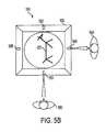
- the floor display system 100could comprise an electronically rotatable and translatable (i.e., movable or shiftable) image 520 .
- the floor display systemcould further comprise a plurality of proximity detectors 530 , 540 , 550 , 560 , for example, included in a sensing device 113 . Based on signals from the proximity detectors, the rotatable and translatable image could be rotated and/or translated to a desired orientation for viewing by a viewer, based on criteria such as how close the viewer is to the floor display system.
- the proximity detectors 530 , 540 , 550 , 560could be, for example, mounted in, attached to, or otherwise associated with edges of the floor covering 102 .
- the proximity detectors 530 , 540 , 550 , 560could respectively be associated with the inclined surfaces 212 , 213 , 214 and 215 of the floor covering.
- the proximity detectorscould be used to determine an orientation of a given image 520 at a given time, depending on the proximity of viewers.
- the proximity detectorscould be coupled to the controller 103 of the floor display system and send signals to the controller.
- a first viewer 580is closer to, say, proximity detector 550 than a second viewer 590 is to proximity detector 540 .
- the determination by the controllercould be made, for example, by executing a suitable hardware and/or software algorithm. Under the conditions shown in FIG. 5A , for example, the controller could cause image 520 to be rotated and/or translated so that it was right side up from the perspective of viewer 580 .
- FIG. 5Bit could be determined based on inputs from the proximity detectors that viewer 590 was closer to proximity detector 540 than viewer 580 was to proximity detector 550 .
- image 520could be rotated and/or translated so that it was right side up from the perspective of viewer 590 .
- itcould be determined based on inputs from the proximity detectors that viewer 595 was closer to proximity detector 530 than viewer 590 was to proximity detector 540 . Under these conditions, image 520 could be rotated and/or translated so that it was right side up from the perspective of viewer 595 .
- a controller 103could execute decision software to implement, for example, decision trees to decide which of a plurality of viewers is closest to, and to which edge of, the floor display system. The controller could then execute corresponding rotation and/or translation software to rotate and/or translate a displayed image accordingly. It is noted that image rotation and/or translation need not occur in 90-degree increments as shown in FIGS. 5A-5C ; finer increments in rotation are possible, down to fractions of a degree.
- image rotation and/or translation softwareis one possibility for implementation
- another possibilitycould be to store images in a plurality of different, fixed orientations, and to select a given image from among the stored images for display depending on a proximity decision.
- proximitymight not be the only basis for selecting a particular image orientation; other bases are possible.
- the imagemight be configured to cycle through a plurality of different orientations periodically. There could be a default orientation for the image if no viewer is sufficiently near, or if a decision on proximity cannot be reached.
- Embodiments of the inventioncould further include a “screen-saver” mode, and either start or stop video output based on the proximity of persons.
- Proximity detectorscould be implemented in a variety of forms, inducing, for example: ultrasonic detectors, thermal detectors, motion detectors, IR (infrared) range finders, electric eyes, cameras, charge coupled devices (CCDs) or other imaging systems.
- an outline 577is intended to represent either part of an electronically-generated graphic, or a actual physical edge of an electronic display device 101 of the floor display system that has a substantially circular form, as opposed to a substantially square or rectangular form as shown in previous figures.
- a substantially circular electronic display device according to embodiments of the present inventioncould be mechanically rotated to re-orient images based on signals from proximity sensors.
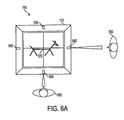
- FIGS. 6A and 6Billustrate electronic (e.g., software-driven) image rotation and/or translation where the electronic display device of the floor display system comprises multiple modules or panels in a substantially square or rectangular configuration as described earlier.
- FIG. 7illustrates that proximity detection need not necessarily be performed by proximity detectors located in or on the floor covering 102 . Instead, for example, proximity detectors could be located in, on, or be otherwise associated with an object near the floor display system 100 .
- FIG. 7shows proximity detectors 715 , 720 , and 730 located on shelving 710 adjacent a floor display system 100 . Based on signals received from proximity detectors 715 , 720 and 730 , a controller 103 of the floor display system could determine which of a plurality of viewers was closest, and orient a rotatable/translatable image 720 accordingly. This determination could be made, for example, based on known distances of respective detectors from the floor display system. Proximity detectors could also be placed in ceilings or suspended from ceilings, for example on tracks.
- floor display systemsmay be deployed in many types of public buildings, including commercial establishments (e.g., markets, stores).
- commercial establishmentse.g., markets, stores
- the plurality of floor display systemscould be used, for example, to announce sales and prices, provide product descriptions, direct customers to specific locations within a commercial establishment, and the like.
- the video/audio content output by a given floor display systemcould, for example, relate to nearby products, such as products on adjacent shelving.
- embodiments of present inventionrelate to configuring floor display systems to generate particular video/audio output, as described below.
- a usermay locally configure a floor display system 100 by physically connecting a configuring device 800 such as a hand-held controller/storage device (CSD) to the floor display system 100 .
- the connectionmay be, e.g., via a direct link 801 , such as a cable link to, e.g., a data port 106 of the floor display system.
- the usermay then download selected video/audio content and/or control software from the device 800 into a storage medium 104 of the floor display system. What data is downloaded to a floor display system may depend, for example, on where the floor display system is located, and thus what content might be relevant.
- the video/audio content downloadedmay be changed by downloading new video/audio content by the same method.
- LANLocal Area Network
- a usermay remotely configure a floor display system, for example, as follows: the user may connect a device 800 to a computer 108 (e.g., a network server; see FIG. 1 ) in a building; this connection could be implemented, for example, wirelessly via IRDA (Infrared Data Association), or via a wired USB link.
- the network sever 108may in turn be connected, by wired or wireless connections (e.g., using a LAN 125 and Ethernet), to a plurality of floor display systems 100 in the building.
- Video/audio content and/or control softwaremay then be downloaded from the device 800 to the network server 108 , and from the network server, to each connected floor display system 100 .
- Data downloaded to a first floor display systemmay be different from data that is downloaded to a second floor display system, depending, for example, on the respective locations of the first and second floor display systems.
- the device 800could be, for example, a CSD, a personal or laptop computer, or the like.
- the server 108could be linked to a database 109 containing content and control software, and a user could direct the server 108 to download content and/or control software from the database 109 to the floor display systems.
- a userneed not connect to a network server computer as described above. Instead, the user need only be in the vicinity of the plurality of floor display systems to be configured, and remotely configure the floor display systems wirelessly from as much as 100 feet away or more.
- the usercould, for example, have a device 800 such as a laptop computer or CSD equipped with a short-range wireless transmitter that can send a wireless signal 802 to communicate with each floor display system 100 in a commercial establishment via, for example, CDMA (code division multiple access) or other similar communication protocol.
- CDMAcode division multiple access
- content and/or control softwarecan be wirelessly downloaded to each floor display system without going through a network.
- the same short-range wireless transmissioncould be used to send data to a network server 108 , which would then distribute the data to each floor display system.
- Video/audio content and/or control softwaremay then be downloaded from the central control location 803 to each LAN, which may then transmit the video/audio content and/or control software to the plurality of floor display systems. Since, as discussed above, it may be desirable to have respective floor display systems in the same establishment generate different video/audio output, each floor display system could have a unique identifier code assigned to it. This identifier code could be provided in a header of the digital data corresponding to the video/audio content and/or control software intended for a particular floor display system. The header information could be used to ensure that each floor display system received the data intended for it.
- satellite network downloadcould be used where the wide area network is provided via satellite constellation.
- a satellitemay broadcast data point-to-multi-point to receivers (e.g., dish receivers) in each establishment containing floor display systems.
- the datamay then be disseminated via LAN, e.g., to respective floor display systems.
- Satellite systemssuch as Motorola's Iridium, Hughes' Direct TV, and Boeing Digital Cinema have already demonstrated such capabilities.
- a floor display system 100may be linked to a POS (point of sale) system of an establishment.
- a POS systemmay be used to gather information about consumer preferences.
- Information about the effectiveness of specific advertising content in generating salescould be gathered, for example, by correlating sales of a given item in an establishment with the timing of given content displayed on a floor display system. This could be accomplished, for example, by electronically cross-referencing sales transactions, at the time they occur, with the scheduling of particular advertising for display on a floor display system.
- the floor display systemcould be connected directly to computers or servers of the POS system.
- a server computer of a LANcould control the scheduling of content on the various floor display systems of an establishment, and provide the scheduling information to a server of the POS system so that it could be correlated in “real time,” i.e., contemporaneously, with sales transactions.
- the scheduling informationcould be correlated with sales records “offline” at a later time.
- Embodiments of a floor display system according to the present inventionmay include interactive features, as discussed below.
- Embodiments of the present inventionmay include the capabilities of asking consumers for information and recording the requested information.
- An illustrative exampleis shown in FIG. 9 .
- the interactivity devicesmay include, for example, a speech input device 900 , such as a microphone, a keyboard or keypad 901 for entering alphanumeric data, a touch-sensitive display screen 902 , a card reader 903 , a bar code scanner 905 , and a coupon dispenser 907 .
- Each of the devicesmay be arranged at a comfortable level for speaking or typing into, or otherwise handling.
- the floor display system 100could include speech recognition software for performing speech recognition processing of utterances directed by a person into the speech input device 900 .
- the floor display systemmight further include pressure sensors 909 under a top surface of a display area of the floor display system.
- the pressure sensors 909could implemented as, for example, thin-film contact switches.
- Each of the foregoing interactivity devicescould be coupled to a controller 103 of the floor display system for sending signals to the controller.
- the controllercould be programmed to perform a desired function depending on the signals received.
- the floor display system 100 and associated interactivity devicesmay be arranged, for example, in a convenient location in a commercial establishment.
- the floor display system 100could generate requests for information, either visually or audibly, to customers passing by.
- the floor display systemcould generate the requests when the proximity of persons was sensed by sensing device 113 .
- the floor display systemcould, for example, request consumer opinion regarding pricing, product specifications, product preferences, coupons, or any other kind of desired information.
- the floor display systemcould prompt a customer to reply, for example, by speaking into the speech input device 900 , by keying in information on the keyboard/keypad 901 , by pressing certain fields in a display of the touch-sensitive screen 902 , by stepping on specified portions of the floor display system to register responses via pressure on the pressure sensors 909 , or by any combination of these.
- the floor display system 100could record customer responses in a storage medium such as storage medium 104 . When enough responses had been collected, the information could be downloaded and analyzed, for example, by brand marketers to determine customer preferences.
- the floor display system 100could also be configured to respond, either by visual or audio output, to a request from a person, where the request is made either by speaking or by entering data using any of the interactivity devices described above (e.g., keyboard/keypad 901 , touch-sensitive screen 902 ).
- the card reader 903could be used, for example, to obtain identity information from customers.
- identity informationmay include, but is not limited to: name, age, history of purchases, frequency of store visits, most commonly purchased items, store credit amount, information pertaining to a store discount, and the like.
- the identity informationcould be, for example, magnetically encoded on a card 904 readable by the card reader 903 .
- the card 904could be, for example, a “smart” card. Smart cards (or electronic cards) are known devices that typically contain an embedded computer chip and are typically the size of a conventional credit or debit card.
- the bar code scanner 905could be used, for example, to enable a customer to scan a coupon 906 .
- the floor display systemcould generate a visual and/or audio message concerning the coupon. The message might, for instance, inform the customer that the coupon is still valid, or that it is worth double, or the like.
- the customermight also be enabled to scan a product at the bar code scanner 905 , and receive a coupon in response.
- a coupon 908could be printed or otherwise generated, and dispensed by the coupon dispenser 907 .
- the coupon dispenser 907could include a counter to count how many coupons are dispensed and for what products. This information could be recorded by the floor display system and used by marketers, for example, to gauge consumer reaction to advertisements, prices, and so on.
- Embodiments of the present inventionmay include an interactivity device implemented as a camera to capture a person's image and cause it to be displayed on a floor display system.
- An illustrative exampleis shown in FIG. 10.
- a camera 1000may be mounted near a floor display system 100 on a floor 1050 , for example, on shelving 1020 .
- the camera 1000may be positioned so as to capture an image of a person 1030 walking or standing near the floor display system.
- the person's image 1060could, for example, be incorporated into an advertisement 1070 displayed on the floor display system.
- the person's imagecould be displayed, for example, as continuous motion video, or in a still image.
- a “frame-grabber” feature of the cameracould be used to create a still image.
- the still imagemight be modified, for example, by image editing software, to convey some entertaining message.
- a milk mustachecould be superimposed onto the face of the person.
- Techniques for enhancing visibility or a visual effect of a displayinclude the use of prisms.
- Diffractive or Fresnel prismsare known and are commercially available, for example, under the brand name ReflexiteTM.
- Such diffractive prismsmay be as thin as a few millimeters or even a fraction of a millimeter.
- a thin layer of material comprising a diffractive prismmay be arranged over an electronic display device of a floor display system. Placing such a diffractive prism over an electronic display device could enable a corresponding display to be more easily visible, particularly along a specific direction.
- FIG. 11illustrates arranging a layer of material 1100 comprising a thin diffractive prism over an electronic display device 101 of a floor display system 100 .
- Embodiments of the present inventionmay provide for carefully controlling the amount of sound generated by an audio device 111 of a floor display system, in particular, for example, with a view to minimizing disturbance to visitors of a commercial establishment or other public building containing a plurality of floor display systems.
- volume and bandwidth of sound output by the audio devicemay be controlled to limit how far the sound travels. For example, lower frequency sound waves (e.g., less than around 200 to 300 Hz) will travel farther with less attenuation than sound waves at higher frequencies.
- embodiments of the inventionmay comprise control mechanisms, such as controller 103 executing suitable software, for controlling audio output to include frequencies slightly higher than around 200 to 300 Hz, and for controlling amplitude so that the audio output is optimally perceivable by a person within a predetermined range.
- control mechanismssuch as controller 103 executing suitable software, for controlling audio output to include frequencies slightly higher than around 200 to 300 Hz, and for controlling amplitude so that the audio output is optimally perceivable by a person within a predetermined range.
- Embodimentsmay further include proximity detectors to provide signals for making determinations relating to what kind of audio output should be generated.
- the proximity detectorscould detect when a person was within a predetermined distance from a floor display system, and send corresponding signals to a controller of the floor display system. Based on the signals received from the proximity detectors, the controller could start or stop audio output, control audio frequency and volume, and the like. Controllers of respective floor display systems could also be linked to a central computer, as described above in connection with the various network configurations possible for floor display systems. The central computer could control the audio output of respective floor display systems to, for example, prevent floor display systems within a predetermined distance of each other from generating audio output simultaneously.
- the audio device 111could further include directional speakers, for example either incorporated into the floor covering or arranged nearby.
- the directional speakerscould be pointed in a direction or directions in which it is expected that persons will approach.
- Proximity detectorscould detect what direction a person is approaching from, and this information could be used by a controller to cause a corresponding directional speaker to generate audio output.
- embodiments of the present inventionmay provide for controlling video and/or audio output based on the proximity of persons. More specifically, based on the proximity of persons, a floor display system according to embodiments of the present invention could start or stop either video or audio output, and adjust image orientation and audio output characteristics, either separately or in combination.
- embodiments of the inventionmay comprise a sturdy protective cover for the electronic display device. Further implementation details, according to possible embodiments, for such a protective cover are discussed below with reference to FIGS. 12A-12B .
- a protective cover 1200may comprise a strong transparent member 1210 , constructed from, by way of example only, glass or a rigid plastic.
- the protective covermay include a hard coating 1220 over the transparent member 1210 , where the coating 1220 is, for example, a diamond-like coating , such as known hard dense carbon coatings that have mechanical properties similar to diamond, but are not as expensive.
- the coating 1220could also be formed from or include plastic or polymeric coatings, such as those used to coat plastic lenses that are well known in the art.
- the protective covermay further include an anti-reflective coating 1230 over the hard coating 1220 .
- the anti-reflective coating 1230may include, for example, multiple layer or organic metal oxides or organic or polymeric coatings with various index of refraction that reduce reflection as known in the lens coating art. Though not shown, in embodiments there could be an anti-reflective coating on a bottom surface 1205 of the transparent member 1210 . Coatings as described in the preceding may reduce glare and resist scratching.
- FIG. 12Bshows an alternative embodiment where hard coating 1220 is omitted and only an anti-reflective coating 1230 is provided on a top surface of the transparent member 1210 . Again, though not shown, in embodiments there could also be an anti-reflective coating on a bottom surface 1205 of the transparent member 1210 .
- Embodiments of the present inventionmay further comprise a removable transparent protective sheet.
- the removable transparent protective sheetmay include an anti-slip feature to help reduce the likelihood of a person slipping when he/she steps on the floor display system, for example due to moisture or wetness.
- the removable transparent protective sheet 1300may be arranged over the protective cover 1200 described above.
- the sheet 1300may have a slip-resistant surface, where the resistance to slipping may be provided by particles such as grit or sand on or incorporated into the surface, by treads, apertures, or any other kind of discontinuity 1300.1 in the surface, by water-absorbing and/or water-dissipating materials in the sheet, or any other material properties of the sheet contributing to slip-resistance, an anti-slip coating on the surface, or any combination of the foregoing.
- the sheetcould cover the entire floor display system, including the electronic display device and the floor covering, or could cover only portions thereof.
- Anti-slip materialcould be, for example, distributed across the floor display system in the form of strips.
- embodimentscould include a plurality of protective sheets in the form of a stack 1301 , where sheets could be individually removable. When a top sheet of the stack became soiled, it could be removed and discarded to expose a fresh sheet below.
- an anti-slip protective sheet materialcould be in the form of a roll of continuous material 1302 , where clean material is dispensed by, for example, a timing mechanism or a dirt-detection mechanism.
- Embodiments of the present inventionmay comprise fragrance technology.
- a stack of layered sheets with a scent or fragrance trapped between each sheetcould be provided in a dispenser used in conjunction with a floor display system.
- the stack of layered sheetscould be arranged in a dispenser provided on or near the floor display system, for example on a stand.
- a layer of transparent scented sheetscould be arranged over all or portions of a floor display system, for example on the inclined surfaces of the floor covering.
- Such a featuremay be especially effective in the marketing of soaps, lotions, cosmetics, laundry detergents, fabric softeners, air fresheners and many other products that utilize scent or fragrance as a primary feature.
- the floor display system 100could include an electromechanical fragrance dispenser 1400 that releases a puff of fragrance on a periodic basis or in conjunction with a given advertisement.
- the dispenser 1400could, for example, be connected to, in or on the floor covering 102 or be otherwise associated with the floor display system.
- Such dispenser deviceshave been developed using small piezoelectric actuators to create very small pumps that spray a small amount of a stored fragrance.
- MEMsMicroelectronic Mechanical Systems
- Embodiments of the present inventionmay provide for theft prevention, as discussed below.
- a floor display systemmay comprise an alarm system configured to be activated if the floor display system is moved without authorization.
- the alarm systemmay comprise an unauthorized-motion motion detection device 1500 able to detect whether the floor display system is moved.
- the device 1500could, for example, be connected to, in or on the floor covering 102 or be otherwise associated with the floor display system 100 .
- the devicecould include, for example, an accelerometer or mercury switch coupled to the controller 103 .
- the deviceUpon detecting a change in position of the floor display system, the device could send a signal to the controller. The controller might then make a determination as to whether an audible and/or visible alarm should be generated.
- the alarmcould include, for example, emitting a siren sound or the like, and/or causing a message such as “WARNING” or “THIEF” to flash on and off on the display device.
- a switch or software settingcould be used to deactivate the alarm system so that the floor display system could be moved without the alarm being generated.
- a floor display systemmay comprise an alarm system including a device able to detect whether the floor display system is moved, as described above.
- the alarm systemmay be configured to emit an electrical pulse if the floor display system is moved without authorization.
- the floor display system 100could include an electrical pulse generator 1501 .
- the electrical pulse generatorcould, for example, be connected to, in or on the floor covering 102 or be otherwise associated with the floor display system.
- the electrical pulse generator 1501could generate an electrical pulse that may cause an unauthorized handler of the floor display system to refrain from further handling of the floor display system.
- a switch or software settingcould be used to deactivate the electrical pulse generator so that the floor display system could be moved without the pulse being generated.
- FIG. 16illustrates details of possible implementations of embodiments of the present invention.
- a floor covering 102 of the floor display system 100may comprise four electronic inverters 1620 , 1630 , 1640 , 1650 for providing power for driving a back light on each of, for example, four LCD displays in a four-panel electronic display device as discussed above with reference to FIG. 3 .
- Powermay be supplied via cables 1660 .
- a controllersuch as controller 103 might be constructed to be small or thin enough to be held within the borders of the floor covering 102 when other components are added to form a more complete assembly, as discussed below.
- FIG. 17is an exploded view of the floor display system 100 .
- a base component 1710may be configured to receive and support a wiring assembly 1720 comprising the four inverters 1620 , 1630 , 1640 , 1650 and cables 1660 as described above.
- a structure 1730may be arranged over the wiring assembly 1720 ; structure 1730 may be formed from plastic or other material and provide support for the inclined surfaces 212 , 213 , 214 , 215 described above.
- the structure 1730may further be configured to receive, for example in recesses formed therein, an electronic display device 101 comprising four separate panels.
- Sections of surfacing material 1750may be placed over structure 1730 , to form inclined surfaces 212 , 213 , 214 , 215 .
- a plate of tempered glass including support ribs 1770may be used as a protective covering 1200 for the electronic display device 101 .
- Components of the floor display systemmay be held together, for example, with adhesive, epoxy or mechanical fasteners.
- a plurality of separable protective sheets 1301may be placed over the tempered glass 1200 .
- the protective sheets 1301may include anti-slip features 1300 . 1 .
- an audio device 110could be included in the above-described assembly.
- the audio devicecould be formed, for example, from thin profile speakers or piezoelectric speakers.
- FIG. 18shows assembled components of a floor display system 100 according to embodiments, resting on a tiled floor 1820 .
- Heat generated by electronics of the floor display systemcould be managed by potting compounds known for such purposes.
- the electronicscould, for example, be potted and bonded to a thin metal plate that would act as a heat sink.
- Embodiments of the present inventionmay further comprise waterproofing elements, to prevent moisture from, for example, foot traffic from damaging electronic components.
- waterproofing elementscould include, for example, potting compounds used as sealants in interstices which could admit damaging moisture.
- a potting compoundcould be used in spaces between the electronic display device and the floor covering to block out moisture.
- a water-resistant substancesuch as silicone could also be used for such a purpose.
- a water-resistant sealcould be formed between a protective cover of the electronic display device and other surfaces of the floor display system.
- a sealant such as siliconecould be used to form the water-resistant seal.
- Embodiments of the present inventionmay include a floor display system implemented as a “track-and-trench” system.
- the track-and-trench systemmay be configured to support the deployment of one or more electronic display devices in a floor.
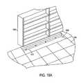
- FIG. 19Ashows an illustrative example.
- a trench 1910is formed in a floor 1905 .
- a track 1915is arranged within the trench.
- Shelving 1920may be arranged adjacent to the track and trench.
- the track 1915may include elements for supplying electric power and for transfer of electronic data.
- electric power cabling and data transfer cablingcould be fastened to, or enclosed within, or otherwise associated with the track 1915 .
- the power cabling and data transfer cablingcould include a plurality of connections for connecting electronic devices thereto, in order for the devices to receive power and/or data via the cabling.
- FIG. 19Bshows an electronic display device 1925 arranged in the trench 1910 .
- the electronic display device 1925may be connected in some way to the track 1915 : for example, it could be hooked or snapped into the track 1915 .
- the electronic display device 1925may include any of the display technologies and capabilities discussed above. Further, though not shown in FIG. 19B , it should be understood that the electronic display device 1925 may be associated with any of the devices discussed above, including audio devices, sensing devices, interactivity devices, network devices, and so on. More specifically, for example, the electronic display device may 1925 be coupled by wired or wireless means to a controller such as controller 103 , and modifiable via the controller to display any content chosen by a user as described above.
- a controllersuch as controller 103
- the electronic display device 1925 and corresponding controllermay be connected to a power supply of the track 1915 .
- the controllermay further be coupled to a storage medium such as storage medium 104 .
- Datamay be stored in the storage medium using, for example, a data port such as data port 106 coupled to a common bus.
- the data portcould be coupled to the data transfer cabling of the track and receive content through the cabling for storage in the storage medium and display on the electronic display device 1925 under the control of the controller.
- the electronic display device 1925may be configurable to display electronically modifiable arbitrary content, support image rotation and/or translation, or otherwise include any of the capabilities discussed above in connection with an electronic display device.
- space in the trench 1910may be closed or covered by fitted sections such as sections 1930 .
- fitted sectionscould be used to close up space in the trench not filled by an electronic display device 1925 .
- Embodiments of the inventioncould further comprise a protective covering 1935 for the electronic display device.
- the protective covering 1935could be transparent in its entirety, or could be partly opaque and include a transparent window 1935 . 1 for viewing the electronic display device.
- FIG. 19Dshows a cross-section along the line 19 D- 19 D.
- Reference numbers 1950 and 1955correspond to a data cable and a power cable, respectively.
- embodiments of the inventionmay further comprise a riser 1960 to raise the electronic display device 1925 to a desired level, and further for providing support, together with the track 1915 , for the protective covering 1935 .
- embodiments including a track-and-trench system as described aboveinclude that, because an electronic display device may be placed below or substantially at floor level, there is no impediment to foot or other traffic presented. Also, a shared power and data supply via a track may enable relatively economical implementations.
- Embodiments of the present inventionmay relate to a floor display system including mechanisms for positioning an electronic display device associated with a floor at a selected inclination for better viewing.
- FIGS. 20A-20Cshow an illustrative example, where FIG. 20B is an orthogonal side view corresponding to FIG. 20 A.
- an electronic display device 2000may be resting on, hingedly fastened to, or otherwise associated with a floor 2015 .
- a positioning device 2020may be coupled to the electronic display device 2000 to position it at a predetermined angle theta relative to the floor 2015 . This may make the electronic display device easier to see from a distance.
- the positioning device 2020may, for example, comprise a spring or other flexible or expandable mechanism. As shown in FIG.
- the positioning device 2020may be compressible or retractable to allow the electronic display device 2000 to be moved closer to the floor 2015 by the pressure of, for example, a person's foot 2030 .
- An advantage of the foregoing arrangementis that an area occupied by the electronic display device may be used for foot or other traffic.
- the electronic display device 2000may include any of the display technologies and capabilities discussed above, and be associated with any of the devices discussed above.
- the electronic display device 2000may be configurable to display electronically modifiable arbitrary content, support image rotation and/or translation, or otherwise include any of the capabilities discussed above in connection with an electronic display device.
- FIGS. 20D-20Eillustrate an alternative embodiment, where FIG. 20D is an orthogonal side view corresponding to FIG. 20 A.
- two electronic display devices 2000each individually configured as described with reference to FIGS. 20A-20C above, may be arranged back-to-back and share a common positioning device 2020
- FIGS. 21A-21CAn electronic display device according to embodiments of the present invention could be formed from very thin, flexible, lightweight materials.
- An illustrative exampleis shown in FIGS. 21A-21C .
- an electronic display device 2100could comprise lightweight materials able to flex and bend as shown in FIG. 21 A. More specifically, the electronic display device 2100 may include a lightweight flexible display element layer 2120 and a lightweight flexible frame 2110 .
- the display element layer 2120may comprise such display elements as small molecule OLEDs, polymeric OLEDs, PLEDs or LEPs.
- FIGS. 21B and 21Care cross-sectional views along lines 21 B— 21 B and 21 C— 21 C, respectively. As shown in FIG.
- the flexible frame 2110may include a lightweight flexible transparent protective layer 2130 and a lightweight flexible backing layer 2160 .
- the display element layer 2120may be arranged between the backing layer 2160 and the transparent protective layer 2130 .
- the transparent protective layercould comprise, for example, polycarbonate, Mylar, or other rugged transparent plastic.
- the electronic display device 2100might further comprise a lightweight flexible thin film battery 2170 to power the display.
- the thin film battery 2170could be arranged between the display element layer 2120 and the backing layer 2160 .
- the electronic display device 2100may further comprise lightweight control electronics 2140 for driving a display of the display element layer.
- the control electronics 2140may be housed with the frame 2110 , laterally to the display element layer 2120 .
- the control electronicscould be arranged, for example, between the display element layer 2120 and the backing layer 2160 (FIG. 21 B), or between the backing layer 2160 and the thin film battery 2170 (FIG. 21 C).
- the electronic display device 2100may be associated with any of the devices discussed above, and be configurable to display electronically modifiable arbitrary content, support image rotation and/or translation, or otherwise include any of the capabilities discussed above in connection with an electronic display device.
- an electronic display device 2100 as described abovewould very lightweight and therefore easily portable.
- the electronic display device 2100could be rolled up and carried under one's arm like a newspaper.
Landscapes
- Physics & Mathematics (AREA)
- General Physics & Mathematics (AREA)
- Engineering & Computer Science (AREA)
- Theoretical Computer Science (AREA)
- Business, Economics & Management (AREA)
- Accounting & Taxation (AREA)
- Marketing (AREA)
- Devices For Indicating Variable Information By Combining Individual Elements (AREA)
Abstract
Description
Claims (63)
Priority Applications (24)
| Application Number | Priority Date | Filing Date | Title |
|---|---|---|---|
| US10/682,435US6917301B2 (en) | 1999-05-04 | 2003-10-10 | Floor display system with variable image orientation |
| US10/759,167US7205903B2 (en) | 1999-05-04 | 2004-01-20 | Interactive and dynamic electronic floor advertising/messaging display |
| JP2006502864AJP2006518870A (en) | 2003-01-22 | 2004-01-20 | Interactive and dynamic electronic floor advertising / message display |
| BR0406569-7ABRPI0406569A (en) | 2003-01-22 | 2004-01-20 | Dynamic interactive interactive message display / floor ad |
| CA2514113ACA2514113C (en) | 2003-01-22 | 2004-01-20 | Interactive and dynamic electronic floor advertising/messaging displaying |
| HK06111128.6AHK1090463B (en) | 2003-01-22 | 2004-01-20 | Interactive and dynamic electronic floor advertising/messaging displaying |
| PCT/US2004/001159WO2004068452A2 (en) | 2003-01-22 | 2004-01-20 | Interactive and dynamic electronic floor advertising/messaging displaying |
| AU2004207380AAU2004207380B2 (en) | 2003-01-22 | 2004-01-20 | Interactive and dynamic electronic floor advertising/messaging displaying |
| KR1020057013243AKR20050088360A (en) | 2003-01-22 | 2004-01-20 | Interactive and dynamic electronic floor advertising/messaging display |
| EP04703560AEP1586083A2 (en) | 2003-01-22 | 2004-01-20 | Interactive and dynamic electronic floor advertising/messaging displaying |
| MXPA05007681AMXPA05007681A (en) | 2003-01-22 | 2004-01-20 | Interactive and dynamic electronic floor advertising/messaging displaying. |
| ARP040100174AR042748A1 (en) | 2003-01-22 | 2004-01-22 | INTERACTIVE ELECTRONIC DISPLAY AND PUBLICITY DYNAMICS / FLOOR MESSAGES |
| TW93101749ATWI302680B (en) | 2003-01-22 | 2004-01-27 | Interactive and dynamic electronic floor advertising/messaging display |
| US10/804,090US20040217877A1 (en) | 1999-05-04 | 2004-03-19 | Flexible electronic display and wireless communication system |
| ARP040100927AR043664A1 (en) | 2003-03-21 | 2004-03-19 | FLEXIBLE ELECTRONIC EXHIBITOR AND WIRELESS COMMUNICATION SYSTEM |
| PCT/US2004/008697WO2004086338A2 (en) | 2003-03-21 | 2004-03-19 | Flexible electronic display and wireless communication system |
| TW093107615ATW200502916A (en) | 2003-03-21 | 2004-03-22 | Flexible electronic display and wireless communication system |
| US11/002,276US7145469B2 (en) | 1999-05-04 | 2004-12-03 | Display system for use on horizontal or non-horizontal surfaces |
| US11/199,130US7358861B2 (en) | 1999-05-04 | 2005-08-09 | Electronic floor display with alerting |
| US11/231,772US7109881B2 (en) | 1999-05-04 | 2005-09-22 | Electronic floor display with weight measurement and reflective display |
| US11/735,908US7511630B2 (en) | 1999-05-04 | 2007-04-16 | Dynamic electronic display system with brightness control |
| US11/769,418US7629896B2 (en) | 1999-05-04 | 2007-06-27 | Floor display system with interactive features and variable image rotation |
| US11/928,264US20080278408A1 (en) | 1999-05-04 | 2007-10-30 | Floor display systems and additional display systems, and methods and computer program products for using floor display systems and additional display system |
| US12/104,191US20080230497A1 (en) | 1999-05-04 | 2008-04-16 | Edge display |
Applications Claiming Priority (10)
| Application Number | Priority Date | Filing Date | Title |
|---|---|---|---|
| US09/304,051US6219876B1 (en) | 1999-05-04 | 1999-05-04 | Floor mat |
| US41875299A | 1999-10-15 | 1999-10-15 | |
| US09/767,846US6417778B2 (en) | 1999-05-04 | 2001-01-24 | Advanced floor mat |
| US10/137,357US6507285B2 (en) | 1999-05-04 | 2002-05-03 | Cleaning system with electronic display |
| US41862602P | 2002-10-12 | 2002-10-12 | |
| US10/285,639US6873266B2 (en) | 1999-05-04 | 2002-11-01 | Electronic floor display |
| US42838702P | 2002-11-21 | 2002-11-21 | |
| US42904402P | 2002-11-23 | 2002-11-23 | |
| US10/438,923US6982649B2 (en) | 1999-05-04 | 2003-05-16 | Floor display system with interactive features |
| US10/682,435US6917301B2 (en) | 1999-05-04 | 2003-10-10 | Floor display system with variable image orientation |
Related Parent Applications (4)
| Application Number | Title | Priority Date | Filing Date |
|---|---|---|---|
| US10/438,923Continuation-In-PartUS6982649B2 (en) | 1999-05-04 | 2003-05-16 | Floor display system with interactive features |
| US10/454,631Continuation-In-PartUS7009523B2 (en) | 1999-05-04 | 2003-06-05 | Modular protective structure for floor display |
| US11/199,130Continuation-In-PartUS7358861B2 (en) | 1999-05-04 | 2005-08-09 | Electronic floor display with alerting |
| US11/735,908Continuation-In-PartUS7511630B2 (en) | 1999-05-04 | 2007-04-16 | Dynamic electronic display system with brightness control |
Related Child Applications (6)
| Application Number | Title | Priority Date | Filing Date |
|---|---|---|---|
| US10/759,167Continuation-In-PartUS7205903B2 (en) | 1999-05-04 | 2004-01-20 | Interactive and dynamic electronic floor advertising/messaging display |
| US10/804,090Continuation-In-PartUS20040217877A1 (en) | 1999-05-04 | 2004-03-19 | Flexible electronic display and wireless communication system |
| US11/002,276Continuation-In-PartUS7145469B2 (en) | 1999-05-04 | 2004-12-03 | Display system for use on horizontal or non-horizontal surfaces |
| US11/199,130Continuation-In-PartUS7358861B2 (en) | 1999-05-04 | 2005-08-09 | Electronic floor display with alerting |
| US11/231,772Continuation-In-PartUS7109881B2 (en) | 1999-05-04 | 2005-09-22 | Electronic floor display with weight measurement and reflective display |
| US11/735,908Continuation-In-PartUS7511630B2 (en) | 1999-05-04 | 2007-04-16 | Dynamic electronic display system with brightness control |
Publications (2)
| Publication Number | Publication Date |
|---|---|
| US20040119602A1 US20040119602A1 (en) | 2004-06-24 |
| US6917301B2true US6917301B2 (en) | 2005-07-12 |
Family
ID=32601268
Family Applications (1)
| Application Number | Title | Priority Date | Filing Date |
|---|---|---|---|
| US10/682,435Expired - LifetimeUS6917301B2 (en) | 1999-05-04 | 2003-10-10 | Floor display system with variable image orientation |
Country Status (1)
| Country | Link |
|---|---|
| US (1) | US6917301B2 (en) |
Cited By (27)
| Publication number | Priority date | Publication date | Assignee | Title |
|---|---|---|---|---|
| US20020156634A1 (en)* | 1999-05-04 | 2002-10-24 | Blum Ronald D. | Floor mat with voice-responsive display |
| US20020174009A1 (en)* | 2001-05-17 | 2002-11-21 | Jeff Myers | Integrated system for gathering commerce information and distributing advertising using a global computer network |
| US20040102247A1 (en)* | 2002-11-05 | 2004-05-27 | Smoot Lanny Starkes | Video actuated interactive environment |
| US20060044149A1 (en)* | 1999-05-04 | 2006-03-02 | Blum Ronald D | Electronic floor display with alerting |
| US20060049955A1 (en)* | 1999-05-04 | 2006-03-09 | Blum Ronald D | Electronic floor display with weight measurement and reflective display |
| US20060087501A1 (en)* | 2003-02-20 | 2006-04-27 | Blum Ronald D | Electronic display device with separately articulated portions for floor advertising/messaging |
| US7079389B2 (en)* | 2003-09-24 | 2006-07-18 | Kabushiki Kaisha Toshiba | Electronic apparatus with unit having inclined surface |
| WO2007015657A1 (en)* | 2005-08-03 | 2007-02-08 | Tigran Armenakovich Akopyan | Aromatic advertising stand |
| US20070188483A1 (en)* | 2006-01-30 | 2007-08-16 | The Samson Group, Llc | Display apparatus for outdoor signs and related system of displays and methods of use |
| US20080030300A1 (en)* | 2005-02-10 | 2008-02-07 | Fujitsu Limited | Information providing apparatus and information providing system |
| US20080106441A1 (en)* | 2006-11-06 | 2008-05-08 | Wayne Gen Chiang | Keyboard in the form of a carpet or a mat |
| WO2008130804A1 (en)* | 2007-04-16 | 2008-10-30 | Intellimat, Inc. | Dynamic electronic display system with brightness control |
| US7456755B2 (en)* | 1999-05-04 | 2008-11-25 | Intellimat, Inc. | Floor mat and system having electronic display device connectable to a network |
| US20090273568A1 (en)* | 2008-05-01 | 2009-11-05 | John Groves Milner | Information management and display system |
| US20090282716A1 (en)* | 2008-05-14 | 2009-11-19 | Barbieri Allen C | Devices and methods for presenting information in traffic areas |
| US20100040844A1 (en)* | 2007-04-25 | 2010-02-18 | Tesserae Technologies | System and method for color-changing decorative construction materials |
| US20100118215A1 (en)* | 2008-10-28 | 2010-05-13 | Bussiere Paul A | Robust display device |
| US20100231576A1 (en)* | 2009-03-13 | 2010-09-16 | Hong Fu Jin Precision Industry (Shenzhen) Co., Ltd | Digital photo frame with mirror function |
| US20110220527A1 (en)* | 2008-09-23 | 2011-09-15 | Airbus Operations Gmbh | Sealable apparatus with data- and energy transmission through electromagnetic induction |
| US20110279962A1 (en)* | 2010-05-13 | 2011-11-17 | Wistron Corporation | Support Frame and Electronic Apparatus |
| US20130143052A1 (en)* | 2006-10-04 | 2013-06-06 | Eastman Chemical Company | Encapsulation of electrically energized articles |
| US9150006B2 (en) | 2011-06-23 | 2015-10-06 | Eastman Chemical Company | Lamination process optimization utilizing neopentyl glycol-modified polyesters |
| TWI511053B (en)* | 2013-05-28 | 2015-12-01 | Univ Nat Taiwan Science Tech | Display system and method thereof |
| US9262015B2 (en)* | 2010-06-28 | 2016-02-16 | Intel Corporation | System for portable tangible interaction |
| US11126393B1 (en) | 2018-04-20 | 2021-09-21 | Quizzit, Inc. | Card products utilizing thin screen displays |
| USD942364S1 (en)* | 2017-05-19 | 2022-02-01 | Mark Chawa | Secondary containment structure for vehicles with handles |
| US20220050537A1 (en)* | 2020-08-14 | 2022-02-17 | Asustek Computer Inc. | Electronic device |
Families Citing this family (33)
| Publication number | Priority date | Publication date | Assignee | Title |
|---|---|---|---|---|
| US20080278408A1 (en)* | 1999-05-04 | 2008-11-13 | Intellimat, Inc. | Floor display systems and additional display systems, and methods and computer program products for using floor display systems and additional display system |
| DE10040680A1 (en)* | 2000-08-19 | 2002-02-28 | Philips Corp Intellectual Pty | TV with additional functions |
| US20040157430A1 (en)* | 2003-02-07 | 2004-08-12 | Asml Netherlands B.V. | Methods and apparatus for processing semiconductor wafers with plasma processing chambers in a wafer track environment |
| JP4625641B2 (en)* | 2004-02-13 | 2011-02-02 | 日立オムロンターミナルソリューションズ株式会社 | Interactive screen system |
| GB0712092D0 (en)* | 2007-06-22 | 2007-08-01 | South Bank Univ Entpr Ltd | Illumination device |
| US20090154198A1 (en)* | 2007-12-14 | 2009-06-18 | Joo Hoon Lee | Reflection type display apparatus |
| JP5396769B2 (en)* | 2008-08-04 | 2014-01-22 | セイコーエプソン株式会社 | Audio output control device, audio output device, audio output control method, and program |
| JP4725625B2 (en)* | 2008-09-30 | 2011-07-13 | ソニー株式会社 | Information processing apparatus, information processing method, and program |
| US9323333B2 (en)* | 2009-12-16 | 2016-04-26 | Avaya Inc. | Detecting patterns with proximity sensors |
| US9086435B2 (en) | 2011-05-10 | 2015-07-21 | Arkalumen Inc. | Circuits for sensing current levels within a lighting apparatus incorporating a voltage converter |
| US9089024B2 (en) | 2010-05-11 | 2015-07-21 | Arkalumen Inc. | Methods and apparatus for changing a DC supply voltage applied to a lighting circuit |
| NZ602965A (en)* | 2010-05-18 | 2014-04-30 | Total Range Design Pty Ltd | Apparatus and method for display of electronic advertising |
| TWI473026B (en)* | 2010-06-30 | 2015-02-11 | Hon Hai Prec Ind Co Ltd | Image display system, display apparatus, and image display method |
| TWI478076B (en)* | 2010-06-30 | 2015-03-21 | Hon Hai Prec Ind Co Ltd | Image management system, display apparatus, and image display method |
| US9192009B2 (en)* | 2011-02-14 | 2015-11-17 | Arkalumen Inc. | Lighting apparatus and method for detecting reflected light from local objects |
| US8941308B2 (en) | 2011-03-16 | 2015-01-27 | Arkalumen Inc. | Lighting apparatus and methods for controlling lighting apparatus using ambient light levels |
| US8939604B2 (en) | 2011-03-25 | 2015-01-27 | Arkalumen Inc. | Modular LED strip lighting apparatus |
| US9060400B2 (en) | 2011-07-12 | 2015-06-16 | Arkalumen Inc. | Control apparatus incorporating a voltage converter for controlling lighting apparatus |
| BE1019933A3 (en)* | 2012-03-08 | 2013-02-05 | Tait Technologies Bvba | PLATFORMS SYSTEM, COMPOSITION OF VIDEO MODULES AND METHOD FOR MOUNTING THE PLATFORMS SYSTEM. |
| TWI492150B (en)* | 2013-09-10 | 2015-07-11 | Utechzone Co Ltd | Method and apparatus for playing multimedia information |
| US9992836B2 (en) | 2015-05-05 | 2018-06-05 | Arkawmen Inc. | Method, system and apparatus for activating a lighting module using a buffer load module |
| US9992829B2 (en) | 2015-05-05 | 2018-06-05 | Arkalumen Inc. | Control apparatus and system for coupling a lighting module to a constant current DC driver |
| US10225904B2 (en) | 2015-05-05 | 2019-03-05 | Arkalumen, Inc. | Method and apparatus for controlling a lighting module based on a constant current level from a power source |
| US9775211B2 (en) | 2015-05-05 | 2017-09-26 | Arkalumen Inc. | Circuit and apparatus for controlling a constant current DC driver output |
| US10568180B2 (en) | 2015-05-05 | 2020-02-18 | Arkalumen Inc. | Method and apparatus for controlling a lighting module having a plurality of LED groups |
| AU2016340057B2 (en)* | 2015-10-14 | 2019-06-27 | Milliken & Company | Flooring system |
| BR102017012338A2 (en)* | 2017-06-09 | 2018-12-26 | Ricardo Pocai | interactive multimedia system, method and carpet for information and ordering of passenger access to aircraft |
| US10582831B2 (en)* | 2017-10-19 | 2020-03-10 | Darren Mckeown | Doormat with changeable display and method therefor |
| EP3920127B1 (en)* | 2019-01-29 | 2024-05-01 | Pocai, Ricardo | Method and system for informing, organizing, transporting, boarding and accommodating passengers in aircraft, equipment and related computer programs |
| US20210141967A1 (en)* | 2019-11-13 | 2021-05-13 | Awan Capital Partners IP, LLC | System and Method of Imaging a Construction Plan onto a Walkable Area |
| EP4191510A4 (en)* | 2020-07-28 | 2024-05-29 | Pocai, Ricardo | SYSTEM AND METHOD FOR PROCESSING BOARDING INFORMATION AND GENERATION OF A BIOMIMETIC VIRTUAL GUIDE, CORRESPONDING EQUIPMENT AND COMPUTER READ MEMORY |
| CN215406379U (en)* | 2021-06-21 | 2022-01-04 | 上海科勒电子科技有限公司 | Intelligent closestool remote controller and intelligent closestool control system |
| WO2024067898A2 (en)* | 2022-09-28 | 2024-04-04 | WE-EF LEUCHTEN GmbH | Display system, method and use |
Citations (148)
| Publication number | Priority date | Publication date | Assignee | Title |
|---|---|---|---|---|
| GB319416A (en) | 1928-07-31 | 1929-09-26 | Morland Micholl Dessau | Improvements in and connected with rubber floor covering and like material |
| GB433133A (en) | 1934-02-08 | 1935-08-08 | Joseph Henry Nicholls | Improvements relating to boot and shoe cleaning appliances |
| US2191704A (en) | 1935-03-26 | 1940-02-27 | Bennett Arthur | Transfer adhesive process and product |
| US2254830A (en) | 1940-05-29 | 1941-09-02 | Norman F Schloss | Bath tub and shower mat |
| US2282672A (en) | 1941-05-14 | 1942-05-12 | Nelson Vern | Sanitary door mat |
| US2512310A (en) | 1949-01-28 | 1950-06-20 | William G Corson | Rubber floor mat |
| US2800215A (en) | 1955-04-13 | 1957-07-23 | Converse Products Inc | Method and means for cleaning type |
| US2843686A (en) | 1948-08-05 | 1958-07-15 | Fed Pacific Electric Co | Push button stations |
| US2919456A (en) | 1958-04-11 | 1960-01-05 | Walter F Spivey | Door mat |
| US3078490A (en) | 1960-11-25 | 1963-02-26 | Kenneth E Etcher | Shoe mat |
| US3083393A (en) | 1961-11-24 | 1963-04-02 | John J Nappi | Shoe sole cleaner |
| US3141522A (en) | 1962-10-29 | 1964-07-21 | Raymond P Fitzpatrick | Disposable absorptive mat |
| US3183116A (en) | 1960-03-14 | 1965-05-11 | Kendall & Co | Method of making perforated adhesive tapes |
| US3300275A (en) | 1963-12-23 | 1967-01-24 | Alfred F Lorman | Germicidal hospital mat |
| US3400421A (en) | 1966-05-19 | 1968-09-10 | Nappi | Shoe sole cleaner |
| US3435481A (en) | 1966-12-06 | 1969-04-01 | Milton Kessler | Protective floor covering |
| US3501797A (en) | 1968-09-09 | 1970-03-24 | John J Nappi | Tacky mat with improved sheet separating means |
| US3517407A (en) | 1967-04-14 | 1970-06-30 | Gerald W Wyant | Disposable carpet made from polyethylene coated sheet material with moisture absorbing paper layers |
| US3578738A (en) | 1969-02-25 | 1971-05-18 | Bissell Inc | Floor mat |
| US3663980A (en) | 1970-09-23 | 1972-05-23 | Roland H Conklin | Door mat |
| US3665543A (en) | 1970-11-19 | 1972-05-30 | John J Nappi | Tacky mat stack |
| US3696459A (en) | 1971-02-12 | 1972-10-10 | Alfred J Kucera | Shoe cleaning mat assembly |
| US3699926A (en) | 1970-10-19 | 1972-10-24 | Rubber Ind Vasto Nv | Floor mat for animals |
| US3717897A (en) | 1970-06-18 | 1973-02-27 | H Amos | Tacky floor pad |
| US3785102A (en) | 1971-11-01 | 1974-01-15 | Edward T Strickland | Tacky floor pad |
| US3886620A (en) | 1971-09-17 | 1975-06-03 | Harold Miller | Door or shoe mat |
| US3906578A (en) | 1973-10-17 | 1975-09-23 | W Rene Huber | Lint remover having localized projections |
| US3909996A (en) | 1974-12-12 | 1975-10-07 | Economics Lab | Modular floor mat |
| US3916401A (en) | 1973-08-24 | 1975-10-28 | Harrod E Freeman | Method of reminding and apparatus for its practice |
| US3930084A (en) | 1974-10-21 | 1975-12-30 | Royal Industries | Plastic decorative inlay in a floor mat |
| US4107811A (en) | 1977-04-19 | 1978-08-22 | Arbrook, Inc. | Tacky floor mat with improved peeling provision |
| US4126854A (en) | 1976-05-05 | 1978-11-21 | Xerox Corporation | Twisting ball panel display |
| US4143103A (en) | 1976-05-04 | 1979-03-06 | Xerox Corporation | Method of making a twisting ball panel display |
| US4143194A (en) | 1977-03-01 | 1979-03-06 | Arbrook, Inc. | Disposable floor mat combination |
| US4328275A (en) | 1980-09-10 | 1982-05-04 | Vargo Louis M | Disposable floor mat |
| EP0009891B1 (en) | 1978-10-05 | 1982-09-29 | Ernst Spirig | Dirt collecting floor mat apparatus |
| US4353944A (en) | 1979-11-10 | 1982-10-12 | Hiroyuki Tarui | Shoe scraper mat |
| DE3147113A1 (en) | 1981-11-27 | 1983-06-01 | Siegfried 8000 München Saumweber | Double plate having luminous elements |
| US4421809A (en) | 1982-09-20 | 1983-12-20 | The Procter & Gamble Company | Floor mat with flock fibers adhesively bonded onto a thin polymeric film |
| FR2532095A1 (en) | 1982-08-12 | 1984-02-24 | Messerschmitt Boelkow Blohm | Activation control of LCD panel |
| US4435451A (en) | 1981-08-17 | 1984-03-06 | Clean-Tex A/S | Floor mats of the washable, dirt adsorbing type |
| US4439474A (en) | 1981-10-30 | 1984-03-27 | The Procter & Gamble Company | Disposable floor mat with improved wet soil absorptivity |
| US4482593A (en) | 1982-09-20 | 1984-11-13 | The Procter & Gamble Company | Flocked floor mat with hydrophilic adhesive |
| US4484250A (en) | 1981-03-16 | 1984-11-20 | Pervel Industries, Inc. | Static dissipative mat |
| US4559250A (en) | 1984-03-21 | 1985-12-17 | Paige Raymond J | Contamination-control mats |
| US4564546A (en) | 1984-12-24 | 1986-01-14 | Kimberly-Clark Corporation | Easily releasable mat holder |
| US4609580A (en) | 1985-01-07 | 1986-09-02 | Kimberly-Clark Corporation | Absorbent floor mat |
| US4614679A (en) | 1982-11-29 | 1986-09-30 | The Procter & Gamble Company | Disposable absorbent mat structure for removal and retention of wet and dry soil |
| DE8701817U1 (en) | 1987-02-06 | 1987-03-19 | Coronet - Werke Heinrich Schlerf Gmbh, 6948 Wald-Michelbach | Doormat |
| US4660828A (en) | 1983-06-15 | 1987-04-28 | Allen Schwab | Reactive control apparatus |
| US4665342A (en) | 1984-07-02 | 1987-05-12 | Cordis Corporation | Screen printable polymer electroluminescent display with isolation |
| GB2182242A (en) | 1985-10-23 | 1987-05-13 | Mccordall Ltd Derek | Entrance mat |
| US4707895A (en) | 1981-05-26 | 1987-11-24 | Clean-Tex A/S | Method of providing nap map or carpet of washable type having increased liquid removal therefrom during washing thereof |
| US4720789A (en) | 1985-10-31 | 1988-01-19 | Bally Manufacturing Corporation | Video exercise or game floor controller with position indicating foot pads |
| US4752114A (en) | 1984-03-08 | 1988-06-21 | Stephen French | Decorative covering including pile fabric and co-terminous optical fiber cables |
| US4798754A (en) | 1987-08-10 | 1989-01-17 | Tomek Lawrence S | Oil-absorbent floor mat |
| US4822669A (en) | 1987-08-21 | 1989-04-18 | Colgate-Palmolive Company | Absorbent floor mat |
| EP0202846B1 (en) | 1985-05-20 | 1989-07-26 | Richard A. Morrison | Non-slip floor mat assembly |
| US4853678A (en) | 1987-02-05 | 1989-08-01 | Bishop Jr Chester O | Advertising device |
| EP0353139A2 (en) | 1988-07-25 | 1990-01-31 | Jorge Julian | Athletic shoe dewaxing mat |
| US4917975A (en) | 1989-02-03 | 1990-04-17 | Guzman Joselito S De | Contamination control mats and methods and apparatus for removing sheets therefrom |
| US4959265A (en) | 1989-04-17 | 1990-09-25 | Minnesota Mining And Manufacturing Company | Pressure-sensitive adhesive tape fastener for releasably attaching an object to a fabric |
| US4974857A (en) | 1988-10-20 | 1990-12-04 | Arachnid, Inc. | Electronic dart game |
| EP0421258A1 (en) | 1989-10-02 | 1991-04-10 | Construction Specialties, Inc. | Floor mat with rigid rails joined by living hinges |
| US5018235A (en) | 1988-09-13 | 1991-05-28 | Kimberly-Clark Corporation | Mat holder |
| WO1991008701A1 (en) | 1989-12-07 | 1991-06-27 | Antonio Rotoli | Cleaning and disinfecting carpet |
| DE4006781A1 (en) | 1990-03-03 | 1991-09-05 | Gerard Brozio | Advertising device for display window and other places - senses person and turns and/or moves according to person's movements to increase attention and observation time |
| EP0199537B1 (en) | 1985-04-19 | 1991-09-25 | Minnesota Mining And Manufacturing Company | Floor mat |
| US5071628A (en) | 1988-02-02 | 1991-12-10 | Jean Alazet | Device for disinfection of soles of shoes |
| DE3915254C2 (en) | 1989-05-10 | 1992-02-20 | Berg Gmbh, 3008 Garbsen, De | |
| EP0354281B1 (en) | 1985-10-31 | 1992-08-19 | Aikoh Co. Ltd. | A deodorant composition and use thereof |
| US5142733A (en) | 1989-12-15 | 1992-09-01 | Kimberly-Clark Corporation | Mat holders |
| EP0365869B1 (en) | 1988-10-11 | 1992-09-16 | Construction Specialties, Inc. | Floor mat with rigid rails joined by living hinges |
| US5161041A (en) | 1990-04-26 | 1992-11-03 | Ois Optical Imaging Systems, Inc. | Lighting assembly for a backlit electronic display including an integral image splitting and collimating means |
| US5204159A (en) | 1991-03-29 | 1993-04-20 | Tan Domingo K L | Deformable, slip-free, anti-skid pads for snow and ice |
| EP0374860B1 (en) | 1988-12-20 | 1993-10-06 | The Dow Chemical Company | Removable polyurethane adhesive and process for preparing the same |
| WO1993020536A1 (en) | 1992-04-06 | 1993-10-14 | Eastman Kodak Company | Cordless electronic stylus and electronic ink-well |
| US5293660A (en) | 1993-04-21 | 1994-03-15 | Park Jai H | Foot scrub mat |
| US5335788A (en) | 1992-03-27 | 1994-08-09 | Sonoco Products Company | Self-opening polyethylene bag stack and process for producing same |
| US5344693A (en) | 1990-03-16 | 1994-09-06 | Bernard Sanders | Component with spacing means |
| EP0448768B1 (en) | 1990-03-13 | 1994-10-12 | Nagase Kenko Corporation | Indoor sport floor mat comprising a plurality of fastenable/unfastenable mat units |
| JPH0690891B2 (en) | 1989-10-16 | 1994-11-14 | リンナイ株式会社 | An actuator with a push button switch |
| EP0624681A2 (en) | 1993-05-10 | 1994-11-17 | E.I. Du Pont De Nemours And Company | Method for preparing carpets having primary and secondary fabric backings |
| JPH0736395A (en) | 1993-07-16 | 1995-02-07 | Toray Ind Inc | Light guide and display object |
| EP0514191B1 (en) | 1991-05-17 | 1995-08-23 | Collie Carpets Limited | Threshold carpeting |
| US5460381A (en) | 1994-10-20 | 1995-10-24 | Smith; Raymond W. | Pirate game apparatus |
| US5461748A (en) | 1993-08-30 | 1995-10-31 | Houei Co., Ltd. | Mat, mat with name and method for anchoring name seal |
| EP0554641B1 (en) | 1992-02-07 | 1996-02-21 | Yugengaisya Towa | Door mat and a method of manufacture thereof |
| US5500267A (en) | 1994-08-22 | 1996-03-19 | Canning; George | Slip-resistant mat for absorbing oil and other liquids |
| EP0573277B1 (en) | 1992-06-02 | 1996-04-10 | Kimberly-Clark Limited | Apertured abrasive absorbent composite nonwoven web |
| US5556685A (en) | 1995-07-25 | 1996-09-17 | Swicegood, Jr.; Glenn M. | Shoe wiping mat assembly |
| JPH08239988A (en) | 1995-03-02 | 1996-09-17 | Meitaku Syst:Kk | Floor surface lighting display device |
| US5561446A (en) | 1994-01-28 | 1996-10-01 | Montlick; Terry F. | Method and apparatus for wireless remote information retrieval and pen-based data entry |
| US5562580A (en) | 1992-03-27 | 1996-10-08 | Sonoco Products Company | Self-opening polyethylene bag stack and process for producing same |
| US5571626A (en) | 1993-05-13 | 1996-11-05 | Polaroid Corporation | Electroluminescent devices comprising polymers, and processes for their use |
| US5589246A (en) | 1994-10-17 | 1996-12-31 | Minnesota Mining And Manufacturing Company | Heat-activatable adhesive article |
| EP0751213A1 (en) | 1995-06-27 | 1997-01-02 | The Procter & Gamble Company | Carpet cleaning compositions and method for cleaning carpets |
| US5604027A (en) | 1995-01-03 | 1997-02-18 | Xerox Corporation | Some uses of microencapsulation for electric paper |
| US5646818A (en) | 1993-08-19 | 1997-07-08 | Siemens Aktiengesellschaft | Electronic appliance with lateral support for display unit and keyboard |
| US5658637A (en) | 1994-09-09 | 1997-08-19 | Foamex L.P. | Floor mat |
| EP0794244A1 (en) | 1996-03-04 | 1997-09-10 | The Procter & Gamble Company | Method of cleaning carpets |
| US5703564A (en) | 1995-11-21 | 1997-12-30 | Klever-Kart, Inc. | Mobile advertising device with electronic transmission capabilities |
| US5723204A (en) | 1995-12-26 | 1998-03-03 | Xerox Corporation | Two-sided electrical paper |
| JPH1057728A (en) | 1996-08-13 | 1998-03-03 | Shinon Denki Sangyo Kk | Mat for removing dust |
| US5747133A (en) | 1996-12-19 | 1998-05-05 | E. I. Du Pont De Nemours And Company | Decorative composite floor coverings |
| EP0839900A1 (en) | 1996-10-31 | 1998-05-06 | The Procter & Gamble Company | Carpet cleaning compositions and method for cleaning carpets |
| US5805117A (en) | 1994-05-12 | 1998-09-08 | Samsung Electronics Co., Ltd. | Large area tiled modular display system |
| DE29811821U1 (en) | 1998-07-02 | 1998-09-17 | Thierling, Jens, 22459 Hamburg | Audiovisual information system |
| US5816550A (en) | 1993-04-26 | 1998-10-06 | Ncr Corporation | Shelf mounting arrangements for electronic shelf displays or similar articles |
| US5815995A (en) | 1996-08-01 | 1998-10-06 | Diversified Industrial Technologies, Inc. | Slip-resistant floor covering system |
| US5826874A (en) | 1996-11-12 | 1998-10-27 | Vr Sports, Inc. | Magnetic golf club swing sensor and golf simulator |
| US5839976A (en) | 1996-10-09 | 1998-11-24 | Darr; Elsie A. | Game mat apparatus |
| US5848830A (en) | 1996-05-10 | 1998-12-15 | Castle; Peter L. | Illuminated floor mat advertiser |
| US5869350A (en) | 1991-02-27 | 1999-02-09 | The Regents Of The University Of California | Fabrication of visible light emitting diodes soluble semiconducting polymers |
| US5886474A (en) | 1995-10-13 | 1999-03-23 | Sony Corporation | Luminescent device having drive-current controlled pixels and method therefor |
| US5885684A (en) | 1997-11-11 | 1999-03-23 | Hefner; Gary L. | Rug having relief pattern, and method for forming |
| JPH11109901A (en) | 1997-08-04 | 1999-04-23 | Masahide Baba | Planar advertisement carrier |
| EP0624125B1 (en) | 1992-01-31 | 1999-06-09 | Ogden Inc. | Slip-resistant, sheet material |
| US5913727A (en) | 1995-06-02 | 1999-06-22 | Ahdoot; Ned | Interactive movement and contact simulation game |
| US5945502A (en) | 1997-11-13 | 1999-08-31 | Xerox Corporation | Electroluminescent polymer compositions and processes thereof |
| US5971761A (en) | 1998-11-12 | 1999-10-26 | Tillman, Sr.; Chitunda | Educational electronic baby mat |
| US6010429A (en) | 1997-07-29 | 2000-01-04 | Prueitt; Daniel S. | Interactive aerobic exercise machine |
| WO2000007811A1 (en) | 1998-08-03 | 2000-02-17 | Milliken Research Corporation | Floor mat exhibiting reduced rippling effects and improved delaminating characteristics of its tufted pile fibers |
| WO2000016682A1 (en) | 1998-09-22 | 2000-03-30 | Minnesota Mining And Manufacturing Company | Mat base and floor mat |
| JP2000105558A (en) | 1998-09-30 | 2000-04-11 | Mitsubishi Materials Corp | Mat for light emitting sign floor using el light emitting sheet |
| EP0648834B1 (en) | 1993-10-19 | 2000-05-17 | Reckitt & Colman Inc. | Carpet cleaner |
| US6067080A (en)* | 1997-02-21 | 2000-05-23 | Electronics For Imaging | Retrofittable apparatus for converting a substantially planar surface into an electronic data capture device |
| WO2000029209A1 (en) | 1998-11-12 | 2000-05-25 | The Procter & Gamble Company | A flexible mat for absorbing liquids comprising polymeric foam materials |
| US6084526A (en) | 1999-05-12 | 2000-07-04 | Time Warner Entertainment Co., L.P. | Container with means for displaying still and moving images |
| EP0512904B1 (en) | 1991-05-03 | 2000-08-16 | COLLINS & AIKMAN ACCESSORY MATS, INC | Floor mat and method of making same |
| WO2001027909A1 (en) | 1999-10-14 | 2001-04-19 | Illumagraphics, Llc | Remotely programmable control device for use in electroluminescent displays and lighting systems |
| US6219876B1 (en) | 1999-05-04 | 2001-04-24 | Tech Mats, L.L.C. | Floor mat |
| US6233776B1 (en) | 1999-05-04 | 2001-05-22 | Tech Mats, L.L.C | Advanced floor mat |
| US6247650B1 (en) | 1998-12-21 | 2001-06-19 | Eastman Kodak Company | Integral image element with display control parameters |
| EP0971064A3 (en) | 1998-07-10 | 2002-01-02 | Milliken & Company | Floor mat solely comprised of monofilament nylon fiber and having an ozone resistant non-staining backing sheet |
| JP2002000059A (en) | 2000-06-20 | 2002-01-08 | Yanmar Agricult Equip Co Ltd | Combine |
| WO2002011110A1 (en) | 2000-07-28 | 2002-02-07 | Jcdecaux Sa | Public site interactive device |
| JP2002062832A (en) | 2000-08-16 | 2002-02-28 | Nippon Signal Co Ltd:The | Floor embedment display device |
| WO2002022972A1 (en) | 2000-09-18 | 2002-03-21 | Roger Planzer | Toilets |
| US6378925B1 (en) | 1997-10-10 | 2002-04-30 | Peter A. Greenlee | Hand grip orthosis |
| US6417778B2 (en) | 1999-05-04 | 2002-07-09 | Tech Mats Llc | Advanced floor mat |
| US20020167500A1 (en)* | 1998-09-11 | 2002-11-14 | Visible Techknowledgy, Llc | Smart electronic label employing electronic ink |
| EP0895745B1 (en) | 1997-08-01 | 2002-12-04 | Rileys Limited | Turtle shaped door closer/stopper cum bootwiper/boot mat/bootscraper made mainly of coco fibre and process of manufacture |
| WO2002065451A9 (en) | 2001-02-14 | 2003-02-13 | Tech Mats Llc | Floor mat with voice-responsive display |
| US20030132924A1 (en)* | 2002-01-16 | 2003-07-17 | Hamilton Robert S. | E-paper labels on recordable/removable media with optical data link and optical power supply |
| US6639578B1 (en)* | 1995-07-20 | 2003-10-28 | E Ink Corporation | Flexible displays |
| US20040041800A1 (en)* | 2002-09-04 | 2004-03-04 | Daniels John James | Thin, lightweight, flexible, bright, wireless display |
| US20040067777A1 (en)* | 2002-10-02 | 2004-04-08 | Salmon Peter C. | Apparatus and method for deploying an information retrieval system |
Family Cites Families (5)
| Publication number | Priority date | Publication date | Assignee | Title |
|---|---|---|---|---|
| US2843868A (en)* | 1956-03-19 | 1958-07-22 | Bruce W Borgstrom | Disposable door mats |
| SE405540B (en)* | 1976-06-10 | 1978-12-18 | Alfa Laval Ab | CONTROL DEVICE FOR AUTOMATIC REMOVAL OF THE MILKING ORGAN |
| DE4303653A1 (en)* | 1993-02-09 | 1994-08-11 | Hoechst Ag | Halogen-free, flame-retardant polymer compositions |
| US5808117A (en)* | 1996-01-22 | 1998-09-15 | Chowdhury; Pritish Kumar | Process for the production of 16-Dehydropregenolone acetate form diosgenin |
| US5826593A (en)* | 1997-05-15 | 1998-10-27 | Haubrich; Joan M. | Hair retainer |
- 2003
- 2003-10-10USUS10/682,435patent/US6917301B2/ennot_activeExpired - Lifetime
Patent Citations (152)
| Publication number | Priority date | Publication date | Assignee | Title |
|---|---|---|---|---|
| GB319416A (en) | 1928-07-31 | 1929-09-26 | Morland Micholl Dessau | Improvements in and connected with rubber floor covering and like material |
| GB433133A (en) | 1934-02-08 | 1935-08-08 | Joseph Henry Nicholls | Improvements relating to boot and shoe cleaning appliances |
| US2191704A (en) | 1935-03-26 | 1940-02-27 | Bennett Arthur | Transfer adhesive process and product |
| US2254830A (en) | 1940-05-29 | 1941-09-02 | Norman F Schloss | Bath tub and shower mat |
| US2282672A (en) | 1941-05-14 | 1942-05-12 | Nelson Vern | Sanitary door mat |
| US2843686A (en) | 1948-08-05 | 1958-07-15 | Fed Pacific Electric Co | Push button stations |
| US2512310A (en) | 1949-01-28 | 1950-06-20 | William G Corson | Rubber floor mat |
| US2800215A (en) | 1955-04-13 | 1957-07-23 | Converse Products Inc | Method and means for cleaning type |
| US2919456A (en) | 1958-04-11 | 1960-01-05 | Walter F Spivey | Door mat |
| US3183116A (en) | 1960-03-14 | 1965-05-11 | Kendall & Co | Method of making perforated adhesive tapes |
| US3078490A (en) | 1960-11-25 | 1963-02-26 | Kenneth E Etcher | Shoe mat |
| US3083393A (en) | 1961-11-24 | 1963-04-02 | John J Nappi | Shoe sole cleaner |
| US3141522A (en) | 1962-10-29 | 1964-07-21 | Raymond P Fitzpatrick | Disposable absorptive mat |
| US3300275A (en) | 1963-12-23 | 1967-01-24 | Alfred F Lorman | Germicidal hospital mat |
| US3400421A (en) | 1966-05-19 | 1968-09-10 | Nappi | Shoe sole cleaner |
| US3435481A (en) | 1966-12-06 | 1969-04-01 | Milton Kessler | Protective floor covering |
| US3517407A (en) | 1967-04-14 | 1970-06-30 | Gerald W Wyant | Disposable carpet made from polyethylene coated sheet material with moisture absorbing paper layers |
| US3501797A (en) | 1968-09-09 | 1970-03-24 | John J Nappi | Tacky mat with improved sheet separating means |
| US3578738A (en) | 1969-02-25 | 1971-05-18 | Bissell Inc | Floor mat |
| US3717897A (en) | 1970-06-18 | 1973-02-27 | H Amos | Tacky floor pad |
| US3663980A (en) | 1970-09-23 | 1972-05-23 | Roland H Conklin | Door mat |
| US3699926A (en) | 1970-10-19 | 1972-10-24 | Rubber Ind Vasto Nv | Floor mat for animals |
| US3665543A (en) | 1970-11-19 | 1972-05-30 | John J Nappi | Tacky mat stack |
| US3696459A (en) | 1971-02-12 | 1972-10-10 | Alfred J Kucera | Shoe cleaning mat assembly |
| US3886620A (en) | 1971-09-17 | 1975-06-03 | Harold Miller | Door or shoe mat |
| US3785102A (en) | 1971-11-01 | 1974-01-15 | Edward T Strickland | Tacky floor pad |
| US3916401A (en) | 1973-08-24 | 1975-10-28 | Harrod E Freeman | Method of reminding and apparatus for its practice |
| US3906578A (en) | 1973-10-17 | 1975-09-23 | W Rene Huber | Lint remover having localized projections |
| US3930084A (en) | 1974-10-21 | 1975-12-30 | Royal Industries | Plastic decorative inlay in a floor mat |
| US3909996A (en) | 1974-12-12 | 1975-10-07 | Economics Lab | Modular floor mat |
| US4143103A (en) | 1976-05-04 | 1979-03-06 | Xerox Corporation | Method of making a twisting ball panel display |
| US4126854A (en) | 1976-05-05 | 1978-11-21 | Xerox Corporation | Twisting ball panel display |
| US4143194A (en) | 1977-03-01 | 1979-03-06 | Arbrook, Inc. | Disposable floor mat combination |
| US4107811A (en) | 1977-04-19 | 1978-08-22 | Arbrook, Inc. | Tacky floor mat with improved peeling provision |
| EP0009891B1 (en) | 1978-10-05 | 1982-09-29 | Ernst Spirig | Dirt collecting floor mat apparatus |
| US4353944A (en) | 1979-11-10 | 1982-10-12 | Hiroyuki Tarui | Shoe scraper mat |
| US4328275A (en) | 1980-09-10 | 1982-05-04 | Vargo Louis M | Disposable floor mat |
| US4484250A (en) | 1981-03-16 | 1984-11-20 | Pervel Industries, Inc. | Static dissipative mat |
| US4707895A (en) | 1981-05-26 | 1987-11-24 | Clean-Tex A/S | Method of providing nap map or carpet of washable type having increased liquid removal therefrom during washing thereof |
| US4435451A (en) | 1981-08-17 | 1984-03-06 | Clean-Tex A/S | Floor mats of the washable, dirt adsorbing type |
| US4439474A (en) | 1981-10-30 | 1984-03-27 | The Procter & Gamble Company | Disposable floor mat with improved wet soil absorptivity |
| DE3147113A1 (en) | 1981-11-27 | 1983-06-01 | Siegfried 8000 München Saumweber | Double plate having luminous elements |
| FR2532095A1 (en) | 1982-08-12 | 1984-02-24 | Messerschmitt Boelkow Blohm | Activation control of LCD panel |
| US4421809A (en) | 1982-09-20 | 1983-12-20 | The Procter & Gamble Company | Floor mat with flock fibers adhesively bonded onto a thin polymeric film |
| US4482593A (en) | 1982-09-20 | 1984-11-13 | The Procter & Gamble Company | Flocked floor mat with hydrophilic adhesive |
| US4614679A (en) | 1982-11-29 | 1986-09-30 | The Procter & Gamble Company | Disposable absorbent mat structure for removal and retention of wet and dry soil |
| US4660828A (en) | 1983-06-15 | 1987-04-28 | Allen Schwab | Reactive control apparatus |
| US4752114A (en) | 1984-03-08 | 1988-06-21 | Stephen French | Decorative covering including pile fabric and co-terminous optical fiber cables |
| US4559250A (en) | 1984-03-21 | 1985-12-17 | Paige Raymond J | Contamination-control mats |
| US4665342A (en) | 1984-07-02 | 1987-05-12 | Cordis Corporation | Screen printable polymer electroluminescent display with isolation |
| US4564546A (en) | 1984-12-24 | 1986-01-14 | Kimberly-Clark Corporation | Easily releasable mat holder |
| US4609580A (en) | 1985-01-07 | 1986-09-02 | Kimberly-Clark Corporation | Absorbent floor mat |
| EP0188005B2 (en) | 1985-01-07 | 1993-12-15 | Kimberly-Clark Corporation | Absorbent floor mat |
| EP0199537B1 (en) | 1985-04-19 | 1991-09-25 | Minnesota Mining And Manufacturing Company | Floor mat |
| EP0202846B1 (en) | 1985-05-20 | 1989-07-26 | Richard A. Morrison | Non-slip floor mat assembly |
| GB2182242A (en) | 1985-10-23 | 1987-05-13 | Mccordall Ltd Derek | Entrance mat |
| US4720789A (en) | 1985-10-31 | 1988-01-19 | Bally Manufacturing Corporation | Video exercise or game floor controller with position indicating foot pads |
| EP0354281B1 (en) | 1985-10-31 | 1992-08-19 | Aikoh Co. Ltd. | A deodorant composition and use thereof |
| US4853678A (en) | 1987-02-05 | 1989-08-01 | Bishop Jr Chester O | Advertising device |
| DE8701817U1 (en) | 1987-02-06 | 1987-03-19 | Coronet - Werke Heinrich Schlerf Gmbh, 6948 Wald-Michelbach | Doormat |
| US4798754A (en) | 1987-08-10 | 1989-01-17 | Tomek Lawrence S | Oil-absorbent floor mat |
| US4822669A (en) | 1987-08-21 | 1989-04-18 | Colgate-Palmolive Company | Absorbent floor mat |
| US5071628A (en) | 1988-02-02 | 1991-12-10 | Jean Alazet | Device for disinfection of soles of shoes |
| EP0353139A2 (en) | 1988-07-25 | 1990-01-31 | Jorge Julian | Athletic shoe dewaxing mat |
| EP0359478B1 (en) | 1988-09-13 | 1995-08-09 | Kimberly-Clark Limited | Improvements in and relating to a mat holder |
| US5018235A (en) | 1988-09-13 | 1991-05-28 | Kimberly-Clark Corporation | Mat holder |
| EP0365869B1 (en) | 1988-10-11 | 1992-09-16 | Construction Specialties, Inc. | Floor mat with rigid rails joined by living hinges |
| US4974857A (en) | 1988-10-20 | 1990-12-04 | Arachnid, Inc. | Electronic dart game |
| EP0374860B1 (en) | 1988-12-20 | 1993-10-06 | The Dow Chemical Company | Removable polyurethane adhesive and process for preparing the same |
| US4917975A (en) | 1989-02-03 | 1990-04-17 | Guzman Joselito S De | Contamination control mats and methods and apparatus for removing sheets therefrom |
| US4959265A (en) | 1989-04-17 | 1990-09-25 | Minnesota Mining And Manufacturing Company | Pressure-sensitive adhesive tape fastener for releasably attaching an object to a fabric |
| DE3915254C2 (en) | 1989-05-10 | 1992-02-20 | Berg Gmbh, 3008 Garbsen, De | |
| EP0421258A1 (en) | 1989-10-02 | 1991-04-10 | Construction Specialties, Inc. | Floor mat with rigid rails joined by living hinges |
| JPH0690891B2 (en) | 1989-10-16 | 1994-11-14 | リンナイ株式会社 | An actuator with a push button switch |
| WO1991008701A1 (en) | 1989-12-07 | 1991-06-27 | Antonio Rotoli | Cleaning and disinfecting carpet |
| US5142733A (en) | 1989-12-15 | 1992-09-01 | Kimberly-Clark Corporation | Mat holders |
| DE4006781A1 (en) | 1990-03-03 | 1991-09-05 | Gerard Brozio | Advertising device for display window and other places - senses person and turns and/or moves according to person's movements to increase attention and observation time |
| EP0448768B1 (en) | 1990-03-13 | 1994-10-12 | Nagase Kenko Corporation | Indoor sport floor mat comprising a plurality of fastenable/unfastenable mat units |
| US5344693A (en) | 1990-03-16 | 1994-09-06 | Bernard Sanders | Component with spacing means |
| US5161041A (en) | 1990-04-26 | 1992-11-03 | Ois Optical Imaging Systems, Inc. | Lighting assembly for a backlit electronic display including an integral image splitting and collimating means |
| US5869350A (en) | 1991-02-27 | 1999-02-09 | The Regents Of The University Of California | Fabrication of visible light emitting diodes soluble semiconducting polymers |
| US5204159A (en) | 1991-03-29 | 1993-04-20 | Tan Domingo K L | Deformable, slip-free, anti-skid pads for snow and ice |
| EP0512904B1 (en) | 1991-05-03 | 2000-08-16 | COLLINS & AIKMAN ACCESSORY MATS, INC | Floor mat and method of making same |
| EP0514191B1 (en) | 1991-05-17 | 1995-08-23 | Collie Carpets Limited | Threshold carpeting |
| EP0624125B1 (en) | 1992-01-31 | 1999-06-09 | Ogden Inc. | Slip-resistant, sheet material |
| EP0554641B1 (en) | 1992-02-07 | 1996-02-21 | Yugengaisya Towa | Door mat and a method of manufacture thereof |
| US5335788A (en) | 1992-03-27 | 1994-08-09 | Sonoco Products Company | Self-opening polyethylene bag stack and process for producing same |
| US5562580A (en) | 1992-03-27 | 1996-10-08 | Sonoco Products Company | Self-opening polyethylene bag stack and process for producing same |
| WO1993020536A1 (en) | 1992-04-06 | 1993-10-14 | Eastman Kodak Company | Cordless electronic stylus and electronic ink-well |
| EP0573277B1 (en) | 1992-06-02 | 1996-04-10 | Kimberly-Clark Limited | Apertured abrasive absorbent composite nonwoven web |
| US5293660A (en) | 1993-04-21 | 1994-03-15 | Park Jai H | Foot scrub mat |
| US5816550A (en) | 1993-04-26 | 1998-10-06 | Ncr Corporation | Shelf mounting arrangements for electronic shelf displays or similar articles |
| EP0624681A2 (en) | 1993-05-10 | 1994-11-17 | E.I. Du Pont De Nemours And Company | Method for preparing carpets having primary and secondary fabric backings |
| US5571626A (en) | 1993-05-13 | 1996-11-05 | Polaroid Corporation | Electroluminescent devices comprising polymers, and processes for their use |
| JPH0736395A (en) | 1993-07-16 | 1995-02-07 | Toray Ind Inc | Light guide and display object |
| US5646818A (en) | 1993-08-19 | 1997-07-08 | Siemens Aktiengesellschaft | Electronic appliance with lateral support for display unit and keyboard |
| US5461748A (en) | 1993-08-30 | 1995-10-31 | Houei Co., Ltd. | Mat, mat with name and method for anchoring name seal |
| EP0648834B1 (en) | 1993-10-19 | 2000-05-17 | Reckitt & Colman Inc. | Carpet cleaner |
| US5561446A (en) | 1994-01-28 | 1996-10-01 | Montlick; Terry F. | Method and apparatus for wireless remote information retrieval and pen-based data entry |
| US5805117A (en) | 1994-05-12 | 1998-09-08 | Samsung Electronics Co., Ltd. | Large area tiled modular display system |
| US5500267A (en) | 1994-08-22 | 1996-03-19 | Canning; George | Slip-resistant mat for absorbing oil and other liquids |
| US5658637A (en) | 1994-09-09 | 1997-08-19 | Foamex L.P. | Floor mat |
| US5589246A (en) | 1994-10-17 | 1996-12-31 | Minnesota Mining And Manufacturing Company | Heat-activatable adhesive article |
| US5460381A (en) | 1994-10-20 | 1995-10-24 | Smith; Raymond W. | Pirate game apparatus |
| US5604027A (en) | 1995-01-03 | 1997-02-18 | Xerox Corporation | Some uses of microencapsulation for electric paper |
| EP0721176B1 (en) | 1995-01-03 | 1999-10-27 | Xerox Corporation | A display medium |
| JPH08239988A (en) | 1995-03-02 | 1996-09-17 | Meitaku Syst:Kk | Floor surface lighting display device |
| US5913727A (en) | 1995-06-02 | 1999-06-22 | Ahdoot; Ned | Interactive movement and contact simulation game |
| EP0751213A1 (en) | 1995-06-27 | 1997-01-02 | The Procter & Gamble Company | Carpet cleaning compositions and method for cleaning carpets |
| US6639578B1 (en)* | 1995-07-20 | 2003-10-28 | E Ink Corporation | Flexible displays |
| US5556685A (en) | 1995-07-25 | 1996-09-17 | Swicegood, Jr.; Glenn M. | Shoe wiping mat assembly |
| US5886474A (en) | 1995-10-13 | 1999-03-23 | Sony Corporation | Luminescent device having drive-current controlled pixels and method therefor |
| US5703564A (en) | 1995-11-21 | 1997-12-30 | Klever-Kart, Inc. | Mobile advertising device with electronic transmission capabilities |
| US5723204A (en) | 1995-12-26 | 1998-03-03 | Xerox Corporation | Two-sided electrical paper |
| EP0794244A1 (en) | 1996-03-04 | 1997-09-10 | The Procter & Gamble Company | Method of cleaning carpets |
| US5848830A (en) | 1996-05-10 | 1998-12-15 | Castle; Peter L. | Illuminated floor mat advertiser |
| US5815995A (en) | 1996-08-01 | 1998-10-06 | Diversified Industrial Technologies, Inc. | Slip-resistant floor covering system |
| JPH1057728A (en) | 1996-08-13 | 1998-03-03 | Shinon Denki Sangyo Kk | Mat for removing dust |
| US5839976A (en) | 1996-10-09 | 1998-11-24 | Darr; Elsie A. | Game mat apparatus |
| EP0839900A1 (en) | 1996-10-31 | 1998-05-06 | The Procter & Gamble Company | Carpet cleaning compositions and method for cleaning carpets |
| US5826874A (en) | 1996-11-12 | 1998-10-27 | Vr Sports, Inc. | Magnetic golf club swing sensor and golf simulator |
| US5747133A (en) | 1996-12-19 | 1998-05-05 | E. I. Du Pont De Nemours And Company | Decorative composite floor coverings |
| US6067080A (en)* | 1997-02-21 | 2000-05-23 | Electronics For Imaging | Retrofittable apparatus for converting a substantially planar surface into an electronic data capture device |
| US6010429A (en) | 1997-07-29 | 2000-01-04 | Prueitt; Daniel S. | Interactive aerobic exercise machine |
| EP0895745B1 (en) | 1997-08-01 | 2002-12-04 | Rileys Limited | Turtle shaped door closer/stopper cum bootwiper/boot mat/bootscraper made mainly of coco fibre and process of manufacture |
| JPH11109901A (en) | 1997-08-04 | 1999-04-23 | Masahide Baba | Planar advertisement carrier |
| US6378925B1 (en) | 1997-10-10 | 2002-04-30 | Peter A. Greenlee | Hand grip orthosis |
| US5885684A (en) | 1997-11-11 | 1999-03-23 | Hefner; Gary L. | Rug having relief pattern, and method for forming |
| US5945502A (en) | 1997-11-13 | 1999-08-31 | Xerox Corporation | Electroluminescent polymer compositions and processes thereof |
| DE29811821U1 (en) | 1998-07-02 | 1998-09-17 | Thierling, Jens, 22459 Hamburg | Audiovisual information system |
| EP0971064A3 (en) | 1998-07-10 | 2002-01-02 | Milliken & Company | Floor mat solely comprised of monofilament nylon fiber and having an ozone resistant non-staining backing sheet |
| WO2000007811A1 (en) | 1998-08-03 | 2000-02-17 | Milliken Research Corporation | Floor mat exhibiting reduced rippling effects and improved delaminating characteristics of its tufted pile fibers |
| US20020167500A1 (en)* | 1998-09-11 | 2002-11-14 | Visible Techknowledgy, Llc | Smart electronic label employing electronic ink |
| WO2000016682A1 (en) | 1998-09-22 | 2000-03-30 | Minnesota Mining And Manufacturing Company | Mat base and floor mat |
| JP2000105558A (en) | 1998-09-30 | 2000-04-11 | Mitsubishi Materials Corp | Mat for light emitting sign floor using el light emitting sheet |
| US5971761A (en) | 1998-11-12 | 1999-10-26 | Tillman, Sr.; Chitunda | Educational electronic baby mat |
| WO2000029209A1 (en) | 1998-11-12 | 2000-05-25 | The Procter & Gamble Company | A flexible mat for absorbing liquids comprising polymeric foam materials |
| US6247650B1 (en) | 1998-12-21 | 2001-06-19 | Eastman Kodak Company | Integral image element with display control parameters |
| US6233776B1 (en) | 1999-05-04 | 2001-05-22 | Tech Mats, L.L.C | Advanced floor mat |
| US20010011399A1 (en) | 1999-05-04 | 2001-08-09 | Blum Ronald D. | Floor mat |
| US6219876B1 (en) | 1999-05-04 | 2001-04-24 | Tech Mats, L.L.C. | Floor mat |
| US6417778B2 (en) | 1999-05-04 | 2002-07-09 | Tech Mats Llc | Advanced floor mat |
| US6084526A (en) | 1999-05-12 | 2000-07-04 | Time Warner Entertainment Co., L.P. | Container with means for displaying still and moving images |
| WO2001027909A1 (en) | 1999-10-14 | 2001-04-19 | Illumagraphics, Llc | Remotely programmable control device for use in electroluminescent displays and lighting systems |
| JP2002000059A (en) | 2000-06-20 | 2002-01-08 | Yanmar Agricult Equip Co Ltd | Combine |
| WO2002011110A1 (en) | 2000-07-28 | 2002-02-07 | Jcdecaux Sa | Public site interactive device |
| JP2002062832A (en) | 2000-08-16 | 2002-02-28 | Nippon Signal Co Ltd:The | Floor embedment display device |
| WO2002022972A1 (en) | 2000-09-18 | 2002-03-21 | Roger Planzer | Toilets |
| WO2002065451A9 (en) | 2001-02-14 | 2003-02-13 | Tech Mats Llc | Floor mat with voice-responsive display |
| US20030132924A1 (en)* | 2002-01-16 | 2003-07-17 | Hamilton Robert S. | E-paper labels on recordable/removable media with optical data link and optical power supply |
| US20040041800A1 (en)* | 2002-09-04 | 2004-03-04 | Daniels John James | Thin, lightweight, flexible, bright, wireless display |
| US20040067777A1 (en)* | 2002-10-02 | 2004-04-08 | Salmon Peter C. | Apparatus and method for deploying an information retrieval system |
Non-Patent Citations (17)
| Title |
|---|
| Co-pending U.S. Appl. No. 10/373,191, filed Feb. 26, 2003. |
| Co-pending U.S. Appl. No. 10/438,923, filed May 16, 2003. |
| Co-pending U.S. Appl. No. 10/454,631, filed Jun. 5, 2003. |
| Co-pending U.S. Appl. No. 10/682,435, filed Oct. 10, 2003. |
| Co-pending U.S. Appl. No. 10/759,167, filed Jan. 20, 2004. |
| Displaying a Winning Glow, Michael Kenward, Technology Review, Jan./Feb. 1999, vol. 102, No. 1, 7 pages. |
| Electronic Ink, Glen Sanders, ebooknet.com, 2 pages, Sep. 20, 1999. |
| Floor Graphics, advertisements, copyright 2002. |
| MMR Journal, Floor Decals New Wrinkle in P-O-P Ads, vol. 16, No. 10, p. 13, Apr. 5, 1999, USA. |
| Patent Abstracts of Japan, vol. 1995, No. 05, Jun. 30, 1995 & JP 07 036395 A (Toray Ind Inc), Feb. 7, 1995. |
| Patent Abstracts of Japan, vol. 1995, No. 1, Feb. 28, 1995 &JP 06 299682 A (Jiyonsuton:KK), Oct. 25, 1994. |
| Patent Abstracts of Japan, vol. 1997, No. 01, Jan. 31, 1997 & JP 08 239988 (Meitaku Syst:KK), Sep. 17, 1996. |
| Patent Abstracts of Japan, vol. 2002 & JP 2002 062832 A (Nippon Signal Co Ltd:The), Feb. 28, 2002. |
| Philadelphia Enquirer, Cherry Hill, N.J., Firm Wants You To Look Down On Its Ads, Regional Newspaper, Aug. 27, 1998, USA. |
| Screen Saviors, Michael Mattis, Business 2.0, Jul. 1999, 1 page. |
| U.K. Patent Office Search Report dated May 28, 2003. |
| What's New, Intelligent Ink, Advertising Material, Popular, 1 page, no date. |
Cited By (40)
| Publication number | Priority date | Publication date | Assignee | Title |
|---|---|---|---|---|
| US7456755B2 (en)* | 1999-05-04 | 2008-11-25 | Intellimat, Inc. | Floor mat and system having electronic display device connectable to a network |
| US20060044149A1 (en)* | 1999-05-04 | 2006-03-02 | Blum Ronald D | Electronic floor display with alerting |
| US20060049955A1 (en)* | 1999-05-04 | 2006-03-09 | Blum Ronald D | Electronic floor display with weight measurement and reflective display |
| US7109881B2 (en) | 1999-05-04 | 2006-09-19 | Intellimats Llc | Electronic floor display with weight measurement and reflective display |
| US20020156634A1 (en)* | 1999-05-04 | 2002-10-24 | Blum Ronald D. | Floor mat with voice-responsive display |
| US7629896B2 (en) | 1999-05-04 | 2009-12-08 | Intellimat, Inc. | Floor display system with interactive features and variable image rotation |
| US7511630B2 (en) | 1999-05-04 | 2009-03-31 | Intellimat, Inc. | Dynamic electronic display system with brightness control |
| US7358861B2 (en) | 1999-05-04 | 2008-04-15 | Intellimats | Electronic floor display with alerting |
| US20020174009A1 (en)* | 2001-05-17 | 2002-11-21 | Jeff Myers | Integrated system for gathering commerce information and distributing advertising using a global computer network |
| US20040102247A1 (en)* | 2002-11-05 | 2004-05-27 | Smoot Lanny Starkes | Video actuated interactive environment |
| US7775883B2 (en)* | 2002-11-05 | 2010-08-17 | Disney Enterprises, Inc. | Video actuated interactive environment |
| US20060087501A1 (en)* | 2003-02-20 | 2006-04-27 | Blum Ronald D | Electronic display device with separately articulated portions for floor advertising/messaging |
| US7079389B2 (en)* | 2003-09-24 | 2006-07-18 | Kabushiki Kaisha Toshiba | Electronic apparatus with unit having inclined surface |
| US20080030300A1 (en)* | 2005-02-10 | 2008-02-07 | Fujitsu Limited | Information providing apparatus and information providing system |
| WO2007015657A1 (en)* | 2005-08-03 | 2007-02-08 | Tigran Armenakovich Akopyan | Aromatic advertising stand |
| US20070188483A1 (en)* | 2006-01-30 | 2007-08-16 | The Samson Group, Llc | Display apparatus for outdoor signs and related system of displays and methods of use |
| US20130143052A1 (en)* | 2006-10-04 | 2013-06-06 | Eastman Chemical Company | Encapsulation of electrically energized articles |
| US9492991B2 (en)* | 2006-10-04 | 2016-11-15 | Eastman Chemical Company | Encapsulation of electrically energized articles |
| US20080106441A1 (en)* | 2006-11-06 | 2008-05-08 | Wayne Gen Chiang | Keyboard in the form of a carpet or a mat |
| WO2008130804A1 (en)* | 2007-04-16 | 2008-10-30 | Intellimat, Inc. | Dynamic electronic display system with brightness control |
| US20100040844A1 (en)* | 2007-04-25 | 2010-02-18 | Tesserae Technologies | System and method for color-changing decorative construction materials |
| US8603613B2 (en) | 2007-04-25 | 2013-12-10 | Tesserae Technologies | System and method for color-changing decorative construction materials |
| US20090273568A1 (en)* | 2008-05-01 | 2009-11-05 | John Groves Milner | Information management and display system |
| US8250795B2 (en) | 2008-05-14 | 2012-08-28 | Barbieri Allen C | Devices and methods for presenting information in traffic areas |
| US20090282716A1 (en)* | 2008-05-14 | 2009-11-19 | Barbieri Allen C | Devices and methods for presenting information in traffic areas |
| US20110220527A1 (en)* | 2008-09-23 | 2011-09-15 | Airbus Operations Gmbh | Sealable apparatus with data- and energy transmission through electromagnetic induction |
| US20100118215A1 (en)* | 2008-10-28 | 2010-05-13 | Bussiere Paul A | Robust display device |
| US7982817B2 (en) | 2008-10-28 | 2011-07-19 | Celestica International Inc. | Robust display device having particular rigid body |
| US20100231576A1 (en)* | 2009-03-13 | 2010-09-16 | Hong Fu Jin Precision Industry (Shenzhen) Co., Ltd | Digital photo frame with mirror function |
| US8498101B2 (en)* | 2010-05-13 | 2013-07-30 | Wistron Corporation | Support frame and electronic apparatus |
| US20110279962A1 (en)* | 2010-05-13 | 2011-11-17 | Wistron Corporation | Support Frame and Electronic Apparatus |
| US9262015B2 (en)* | 2010-06-28 | 2016-02-16 | Intel Corporation | System for portable tangible interaction |
| US9150006B2 (en) | 2011-06-23 | 2015-10-06 | Eastman Chemical Company | Lamination process optimization utilizing neopentyl glycol-modified polyesters |
| TWI511053B (en)* | 2013-05-28 | 2015-12-01 | Univ Nat Taiwan Science Tech | Display system and method thereof |
| CN103826151B (en)* | 2013-05-28 | 2017-04-26 | 友达光电股份有限公司 | Display system and method thereof |
| USD942364S1 (en)* | 2017-05-19 | 2022-02-01 | Mark Chawa | Secondary containment structure for vehicles with handles |
| US11126393B1 (en) | 2018-04-20 | 2021-09-21 | Quizzit, Inc. | Card products utilizing thin screen displays |
| US11520558B2 (en) | 2018-04-20 | 2022-12-06 | Quizzit, Inc. | Card products utilizing thin screen displays |
| US11836413B2 (en)* | 2018-04-20 | 2023-12-05 | Quizzit, Inc. | Card products utilizing video screen displays |
| US20220050537A1 (en)* | 2020-08-14 | 2022-02-17 | Asustek Computer Inc. | Electronic device |
Also Published As
| Publication number | Publication date |
|---|---|
| US20040119602A1 (en) | 2004-06-24 |
Similar Documents
| Publication | Publication Date | Title |
|---|---|---|
| US6917301B2 (en) | Floor display system with variable image orientation | |
| AU2003287055B2 (en) | Floor display system with variable image orientation | |
| US7629896B2 (en) | Floor display system with interactive features and variable image rotation | |
| US7205903B2 (en) | Interactive and dynamic electronic floor advertising/messaging display | |
| US20080230497A1 (en) | Edge display | |
| US7009523B2 (en) | Modular protective structure for floor display | |
| US7145469B2 (en) | Display system for use on horizontal or non-horizontal surfaces | |
| CA2516509A1 (en) | Electronic display device for floor advertising/messaging | |
| CN100403346C (en) | Ground Display System with Variable Image Orientation | |
| AU2004207380B2 (en) | Interactive and dynamic electronic floor advertising/messaging displaying | |
| TWI302680B (en) | Interactive and dynamic electronic floor advertising/messaging display | |
| WO2008128245A1 (en) | Display | |
| CN100496374C (en) | Modular protective structure for floor display | |
| HK1087823B (en) | Floor display system with variable image orientation | |
| HK1087823A1 (en) | Floor display system with variable image orientation | |
| KR200219291Y1 (en) | Multi-function automatic sale advertising device possible in separation | |
| HK1090463B (en) | Interactive and dynamic electronic floor advertising/messaging displaying | |
| HK1088198B (en) | Modular protective structure for floor display |
Legal Events
| Date | Code | Title | Description |
|---|---|---|---|
| AS | Assignment | Owner name:INTELLIMATS, LLC, VIRGINIA Free format text:ASSIGNMENT OF ASSIGNORS INTEREST;ASSIGNORS:BLUM, RONALD D.;KOKONASKI, WILLIAM;THIBODEAU, JOSEPH A.;AND OTHERS;REEL/FRAME:015010/0833;SIGNING DATES FROM 20040126 TO 20040222 | |
| FEPP | Fee payment procedure | Free format text:PAYOR NUMBER ASSIGNED (ORIGINAL EVENT CODE: ASPN); ENTITY STATUS OF PATENT OWNER: SMALL ENTITY | |
| STCF | Information on status: patent grant | Free format text:PATENTED CASE | |
| AS | Assignment | Owner name:SPI INVESTMENTS, LLC, VIRGINIA Free format text:SECURITY AGREEMENT;ASSIGNOR:INTELLIMATS, LLC;REEL/FRAME:016580/0851 Effective date:20050921 | |
| FEPP | Fee payment procedure | Free format text:PAYER NUMBER DE-ASSIGNED (ORIGINAL EVENT CODE: RMPN); ENTITY STATUS OF PATENT OWNER: SMALL ENTITY Free format text:PAYOR NUMBER ASSIGNED (ORIGINAL EVENT CODE: ASPN); ENTITY STATUS OF PATENT OWNER: SMALL ENTITY | |
| AS | Assignment | Owner name:INTELLIMATS, LLC, VIRGINIA Free format text:RELEASE BY SECURED PARTY;ASSIGNOR:SPI INVESTMENTS, LLC;REEL/FRAME:018654/0160 Effective date:20061025 | |
| AS | Assignment | Owner name:INTELLIMAT, INC., VIRGINIA Free format text:CHANGE OF NAME;ASSIGNOR:INTELLIMATS, LLC;REEL/FRAME:020563/0472 Effective date:20061024 | |
| AS | Assignment | Owner name:NEW RIVER MANAGEMENT IV, LP, VIRGINIA Free format text:SECURITY AGREEMENT;ASSIGNOR:INTELLIMAT, INC.;REEL/FRAME:020593/0118 Effective date:20071019 | |
| FPAY | Fee payment | Year of fee payment:4 | |
| AS | Assignment | Owner name:COLLIN PEEL, VIRGINIA Free format text:ASSIGNMENT OF ASSIGNORS INTEREST;ASSIGNOR:INTELLIMAT, INC.;REEL/FRAME:028656/0195 Effective date:20111108 | |
| FPAY | Fee payment | Year of fee payment:8 | |
| FPAY | Fee payment | Year of fee payment:12 |