US6916988B1 - Electrical connector with frustro conical snap fit retaining ring - Google Patents
Electrical connector with frustro conical snap fit retaining ringDownload PDFInfo
- Publication number
- US6916988B1 US6916988B1US10/939,619US93961904AUS6916988B1US 6916988 B1US6916988 B1US 6916988B1US 93961904 AUS93961904 AUS 93961904AUS 6916988 B1US6916988 B1US 6916988B1
- Authority
- US
- United States
- Prior art keywords
- end portion
- arms
- outlet end
- frustro
- electrical
- Prior art date
- Legal status (The legal status is an assumption and is not a legal conclusion. Google has not performed a legal analysis and makes no representation as to the accuracy of the status listed.)
- Expired - Lifetime
Links
- 239000000463materialSubstances0.000claimsabstractdescription7
- 239000004020conductorSubstances0.000claimsdescription10
- 238000003780insertionMethods0.000claimsdescription7
- 230000037431insertionEffects0.000claimsdescription7
- 230000000295complement effectEffects0.000claimsdescription4
- 230000000694effectsEffects0.000claimsdescription2
- 239000012858resilient materialSubstances0.000claims1
- 229910000639Spring steelInorganic materials0.000abstractdescription3
- 239000002436steel typeSubstances0.000abstract1
- 238000010276constructionMethods0.000description2
- 239000002184metalSubstances0.000description2
- 229910052751metalInorganic materials0.000description2
- HCHKCACWOHOZIP-UHFFFAOYSA-NZincChemical compound[Zn]HCHKCACWOHOZIP-UHFFFAOYSA-N0.000description1
- 230000000712assemblyEffects0.000description1
- 238000000429assemblyMethods0.000description1
- 238000005452bendingMethods0.000description1
- 238000005058metal castingMethods0.000description1
- 229910001092metal group alloyInorganic materials0.000description1
- 238000012986modificationMethods0.000description1
- 230000004048modificationEffects0.000description1
- 230000000750progressive effectEffects0.000description1
- 230000000717retained effectEffects0.000description1
- 238000000926separation methodMethods0.000description1
- 229910052725zincInorganic materials0.000description1
- 239000011701zincSubstances0.000description1
Images


Classifications
- H—ELECTRICITY
- H02—GENERATION; CONVERSION OR DISTRIBUTION OF ELECTRIC POWER
- H02G—INSTALLATION OF ELECTRIC CABLES OR LINES, OR OF COMBINED OPTICAL AND ELECTRIC CABLES OR LINES
- H02G3/00—Installations of electric cables or lines or protective tubing therefor in or on buildings, equivalent structures or vehicles
- H02G3/02—Details
- H02G3/06—Joints for connecting lengths of protective tubing or channels, to each other or to casings, e.g. to distribution boxes; Ensuring electrical continuity in the joint
- H02G3/0616—Joints for connecting tubing to casing
- H02G3/0691—Fixing tubing to casing by auxiliary means co-operating with indentations of the tubing, e.g. with tubing-convolutions
Definitions
- This inventionrelates to a snap fit electrical connector for connecting an electrical conductor to an electrical box, and more specifically to an electrical connector having a detachable snap fit, retaining ring having a face portion and a generally frustro-conical shape circumscribing the face portion and having integrally formed thereon a series of resilient locking tangs and grounding tangs.
- Electrical connectorsare commonly used for attaching electrical conductors, cables, wires, electrical metal tubing or the like to an electric box, e.g. a junction box, outlet box, switch box or other similar type of electric box.
- Such known electrical connectorsare either of a type that are secured to an electric box by a threaded lock nut or by means of a circular snap fit retaining ring of the type disclosed on the above identified co-pending applications or as disclosed in U.S. patents, such as U.S. Pat. Nos. 6,444,907; 5,189,258; 5,266,050; 5,171,164; 2,744,769 and 1,483,218 for example. Reference is also made to U.S. Pat. No.
- 6,768,057which is directed to a right angle type connector formed of a pair of sheet metal stampings fitted together and secured to an electrical box with a snap fit arrangement.
- Connectors formed as connector caps which are adapted to be fitted over the end of a conductor, cable or wires, such as disclosed in U.S. Pat. No. 4,880,387,are also known. While such prior known connectors can be satisfactorily used for their intended purposes, efforts are constantly being made to improve upon the known electrical connectors.
- the disclosure hereincomprises another effort to advance or improve the manner of forming and/or securing an electrical connector to an electric box by a snap fit action.
- An object of this inventionis to provide an electrical connector with a frustro-conically shaped retaining ring having integrally formed locking tangs and electrical grounding tangs.
- Another object of this inventionis to provide for an electrical connector assembly that includes an electrical connector body having an outlet end portion having a complementary frustro-conical retaining ring that is readily fitted to and retained on the outlet end portion of the connector body.
- Another objectis to provide a connector assembly comprising a connector body having an outlet portion free of any retaining flanges and an associated snap fit retainer ring circumscribing the outlet end portion.
- Another objectis to provide a retaining ring having a face portion with outwardly flaring circumscribing arms or sides having locking and grounding tangs that are readily formed out of a surface of the respective arms or side.
- Another objectis to provide a retaining ring having a frustro-conical shape with a first series of tangs for securing the retaining ring relative to an electrical box and a second series of tangs for effecting a positive electrical ground with an associated electrical box when fitted onto the end of a connector body.
- Another objectis to provide a frustro-conically shaped retaining ring that can be readily formed from a blank of spring steel.
- Another objectis to provide or an electrical connector assembly that is relatively simple to fabricate and positive in operation.
- an electrical connector assemblythat includes a connector body having an inlet end portion for receiving an electrical conductor and an outlet portion which is adapted to be inserted through a knockout hole of an electric box, e.g. an electric outlet box or the like.
- a radially outwardly extending flangecircumscribes an intermediate portion of the connector body to function as a stop to limit the insertion of the outlet end portion of the connector body through the knockout hole of an electric box.
- the outlet end portionmay be provided with an outer surface that converges or tapers inwardly toward the outlet opening thereof.
- Formed on the surface of the outlet end portionare one or more retaining lugs, which may be circumferentially spaced about the outlet end portion.
- a frustro-conically shaped snap ringis fitted onto the outlet end portion.
- the retaining ringwhich is initially formed from a blank of sheet material having a cruciform shape, has a face portion with a central opening wherein the radiating arms of the cruciform blank are disposed about the face portion to define a frustro-conical ring.
- the ring so formedis provided with a blanked out or die cut tangs to define locking tangs and grounding tangs.
- the frustro-conical ring so formedalso has a slot adapted to receive the retaining lug when the retaining ring is fitted onto the outlet end portion of the connector body so that the free ends of the ring engage the inner periphery of the knockout hole of an electric box for electrical continuity and grounding.
- the cruciform armsare arranged to be folded relative to the front or face forming portion of the blank provided with a central opening to define a unitary frustro-conically shaped cup-like member to compliment or be fitted to the outlet end portion of the connector body.
- the retaining ring thus formedis fitted over or onto the outlet end portion whereby the retaining slot formed in the ring of arms is adapted to receive the complementary retaining lug formed on the surface of the outlet end portion for retaining the ring on the outlet end portion of the connector body.
- the connector assemblycan be readily inserted through the knockout opening of an electric box wherein the locking tangs will spring outwardly to lock the connector assembly to the electric box with the grounding tangs or free ends of the arms being biased or urged against the internal periphery of the knockout hole to effect a positive electric ground, due to the inherent resiliency of the respective tangs and the material from which they are formed.
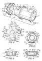
- FIG. 1is an exploded perspective view of the electrical connector assembly.
- FIG. 2is a plan view of the blank from which the retaining ring of the present invention is formed.
- FIG. 3is a detail front view of the retainer ring.
- FIG. 4is a detail side view of the retaining ring.
- FIG. 5is a detail end view of FIG. 4 .
- FIG. 6is a sectional view of the retainer ring taken along line 6 — 6 on FIG. 3 .
- FIG. 7is a side view of the connector assembly illustrating the alignment thereof relative to the knockout opening of an electric box.
- FIG. 8is a section side view illustrating the connector assembly secured to an electric box, and taken along line 8 — 8 on FIG. 10 .
- FIG. 9is a sectional side view taken along line 9 — 9 on FIG. 10 .
- FIG. 10is a fragmentary front view of the connector assembly secured to an electric box as viewed from the inside of the box.
- the connector assembly 10includes a connector body 11 , which is usually formed of metal casting, e.g. zinc or other suitable metallic alloy.
- the connector body 11is formed with an inlet end portion 11 A and an outlet end portion 11 B and having a bore 12 extending therethrough.
- a radially outwardly extending flange 13which functions as a stop to limit the amount that the connector body 11 may be inserted through the knockout hole 14 of an electric box 15 , as noted in FIG. 8 .
- the outer surface S of the outlet end portion 11 Bslopes, tapers or converges toward the outlet opening 16 whereby the outer surface S of the outlet end portion 11 B has a generally frustro-conical configuration.
- Formed on the surface S of the outlet end portion 11 Bis an outwardly projecting retainer lug 17 .
- two such lugs 17are shown disposed 180° apart about the outer circumference of the outlet end portion 11 B.
- the connector assembly 10also includes a snap fit retaining ring 18 .
- the retaining ring 18is integrally formed from a blank 19 of spring steel material.
- the blank 19is initially formed or stamped to define a generally cruciform shape.
- the cruciform shapeis provided with a face portion 20 having central opening or hole 20 A and having four generally radially extending arms defining two pairs of oppositely disposed arms AA and BB.
- the opposed pair of arms AAare each provided with a retaining slot 21 .
- the opposed pair of arms BBare blanked or formed to define a locking tang 22 and to either side thereof an electrical grounding tang 23 , 23 .
- the locking tang 22is slightly shorter than the adjacent grounding tangs 23 , 23 .
- the arrangementis such that the free end of the locking tangs 22 are formed so as to engage the inside surface of the electric box 15 in the assembled portion, as best seen in FIG.
- the respective arms AA and BBare subjected to a series of progressive bending dies which will gradually bend the respective arms relative about a foldline f, which defines the face or front portion 20 , whereby the arms AA and BB form a cup having circumscribing frustro-conical or outwardly flaring sides to define a ring which complements the conical surface S of the outlet end portion 11 B, as seen in FIG. 1 .
- the locking tangs 22are outwardly cantileverly bent or displaced relative to the surface of the ring at a slightly greater outwardly angle or slope than the adjacent grounding tangs 23 and the slope of arms AA.
- the retaining ringWith the retaining ring so formed, it can be readily fitted onto the outlet end portion 11 B whereby the inherent resiliency of the arms AA will cause the retainer slots 22 to snap fit onto the retaining lug 17 when slots 21 are placed in alignment with lugs 17 .
- the arrangementis such that the retainer ring 18 will be firmly and positively secured to the outlet end portion 11 B as seen in FIG. 8 . Yet, due to the inherent resiliency of the material of the retaining ring 18 , it can be easily detached from the outlet end portion 11 B when removal is desired, without destroying the ring 18 by lifting arms AA free of the retaining lugs 17 .
- the connector assembly 10can be readily secured to an electric box 10 by simply aligning the assembly 10 with a knockout hole 14 , as best seen in FIG. 7 , and inserting the outlet end portion into the knockout hole 14 until the flange 13 engages the outer side of the electric box 15 . In doing so, the respective tangs 22 , 23 and the free ends 24 of arms AA will depress inwardly to permit insertion of the assembly 10 . When the assembly is fully seated in the knockout hole 14 , the locking tangs 22 will normally spring outwardly to secure the assembly 10 to the electric box 15 , as noted in FIG. 9 .
- the inherent resiliency of the grounding tangs 23 , 23 and the free end 24 of arms AAare normally biased in engagement with the internal periphery of the knockout hole 14 to ensure a positive electrical ground with the electric box 15 .
- the engagement of the free ends 24 of arms AA against the inner periphery of the knockout hole 14as noted in FIG. 8 , further ensures the firm securement of the retaining slot 21 with the retaining lugs 17 , so as to prohibit any disengagement of the retaining ring 18 from the connector body 11 .
- the wire conductor 25may be secured to the connector assembly 10 either before or after the assembly 10 has been secured to the electric box 15 .
- the conductor wire 25is simply inserted into the inlet end portion 11 A and secured in position by a suitable securing means.
- the securing meansis illustrated as a set screw 26 .
- other conventional forms of securing meansmay be used, than the set screw 26 illustrated.
- the snap fit retaining ring 18can be simply formed from a cruciform shaped blank 19 whereby the opposed radially extending arms AA and BB can be readily formed into a cup having a generally frustro-conically shaped sidewalls complementing the slope of the outlet end portion 11 A, and whereby the retainer ring 18 can be readily secured to the connector body simply by the inter-engagement of slots 21 with its complementary lugs 17 .
- the retainer ring 18is positively secured to the connector body in a manner to prohibit any unintentional separation.
- the tangs 22 , 23which are formed integral with ring 18 , are shaped and formed so that the locking tangs 22 secure the assembly 10 to an electric box 15 while the grounding tangs 23 ensure a positive electrical ground of the assembly 10 with the associated electric box 15 .
Landscapes
- Engineering & Computer Science (AREA)
- Architecture (AREA)
- Civil Engineering (AREA)
- Structural Engineering (AREA)
- Details Of Connecting Devices For Male And Female Coupling (AREA)
Abstract
Description
Claims (10)
Priority Applications (18)
| Application Number | Priority Date | Filing Date | Title |
|---|---|---|---|
| US10/939,619US6916988B1 (en) | 2004-07-12 | 2004-09-13 | Electrical connector with frustro conical snap fit retaining ring |
| US11/100,250US7064272B2 (en) | 2004-09-13 | 2005-04-06 | Snap in electrical connector assembly with unidirectional wire conductor retainer ring |
| US11/151,374US7075007B2 (en) | 2004-09-13 | 2005-06-13 | Snap fit electrical connector assembly with conical outer snap fit retainer and one or more internal snap fit wire retainers |
| CA2518666ACA2518666C (en) | 2004-09-13 | 2005-09-09 | Snap fit electrical connector assembly |
| US11/258,990US7057107B2 (en) | 2004-09-13 | 2005-10-26 | Snap fit electrical connector assembly with conical outer snap fit retainer and externally mounted internal wire retainer |
| US11/364,435US7205489B2 (en) | 2004-09-13 | 2006-02-28 | Snap fit electrical connector assembly with operating tool for facilitating the connection of a connector assembly to an electrical box |
| US11/400,606US7154042B2 (en) | 2004-09-13 | 2006-04-07 | Electrical connector with snap fit retainer ring constructed to enhance the connection of the connector to an electrical box |
| US11/403,099US7151223B2 (en) | 2004-09-13 | 2006-04-12 | Snap fit electrical connector assembly with outer frustro conical retainer ring and internal unidirectional snap fit wire conductor retainer |
| US11/501,131US7488905B2 (en) | 2004-09-13 | 2006-08-08 | Electrical connector with outer retainer ring and internal unidirectional conductor retainer |
| US11/545,640US7214890B2 (en) | 2004-09-13 | 2006-10-10 | Electrical connector having an outlet end angularly disposed relative an inlet end with outer retainer ring about the outlet end and internal unidirectional conductor retainer in the inlet end |
| US11/726,012US7358448B2 (en) | 2004-09-13 | 2007-03-20 | Electrical connector assembly with frusto-conical snap fit retaining ring for enhancing electrical grounding of the connector assembly to an electrical box and installation tool therefor |
| US11/903,410US7952034B2 (en) | 2004-09-13 | 2007-09-21 | Strap type electrical connector with frustro-conical retaining ring and improved clamping strap for either nonmetallic cables or armor or metal clad cables |
| US12/006,946US7723623B2 (en) | 2004-09-13 | 2008-01-08 | Electrical duplex connector having an integrally formed connector body with a frustro-conical retaining ring and unidirectional cable retainers |
| US12/151,245US7820922B2 (en) | 2004-09-13 | 2008-05-05 | Electrical offset nipple connector with frustro-conical retaining rings |
| US12/319,304US7645947B2 (en) | 2004-09-13 | 2009-01-06 | Electrical connector with outer retainer ring and internal unidirectional conductor retainer |
| US12/322,276US8143535B2 (en) | 2004-09-13 | 2009-01-30 | Electrical connector assembly with enhanced grounding |
| US12/658,482US8119933B2 (en) | 2004-09-13 | 2010-02-09 | Duplex electrical connector with frustro-conical retaining ring and crimped inlet end |
| US12/658,478US8350163B2 (en) | 2004-09-13 | 2010-02-09 | Electrical connector having snap in frustro-conical retaining ring with improved conductivity |
Applications Claiming Priority (2)
| Application Number | Priority Date | Filing Date | Title |
|---|---|---|---|
| US58712104P | 2004-07-12 | 2004-07-12 | |
| US10/939,619US6916988B1 (en) | 2004-07-12 | 2004-09-13 | Electrical connector with frustro conical snap fit retaining ring |
Related Child Applications (1)
| Application Number | Title | Priority Date | Filing Date |
|---|---|---|---|
| US11/100,250Continuation-In-PartUS7064272B2 (en) | 2004-09-13 | 2005-04-06 | Snap in electrical connector assembly with unidirectional wire conductor retainer ring |
Publications (1)
| Publication Number | Publication Date |
|---|---|
| US6916988B1true US6916988B1 (en) | 2005-07-12 |
Family
ID=34713870
Family Applications (1)
| Application Number | Title | Priority Date | Filing Date |
|---|---|---|---|
| US10/939,619Expired - LifetimeUS6916988B1 (en) | 2004-07-12 | 2004-09-13 | Electrical connector with frustro conical snap fit retaining ring |
Country Status (1)
| Country | Link |
|---|---|
| US (1) | US6916988B1 (en) |
Cited By (58)
| Publication number | Priority date | Publication date | Assignee | Title |
|---|---|---|---|---|
| US20060054343A1 (en)* | 2004-09-13 | 2006-03-16 | Delbert Auray | Snap fit electrical connector assembly with conical outer snap fit retainer and externally mounted internal wire retainer |
| US7060900B1 (en) | 2006-01-24 | 2006-06-13 | Arlington Industries, Inc. | Snap engagement electrical fitting with flangeless connector body |
| US7064273B1 (en)* | 2004-07-12 | 2006-06-20 | Bridgeport Fittings, Inc. | Electrical connector with conical split snap ring retainer |
| US20060141827A1 (en)* | 2004-09-13 | 2006-06-29 | Delbert Auray | Snap fit electrical connector assembly with operating tool for facilitating the connection of a connector assembly to an electrical box |
| US20060180330A1 (en)* | 2004-09-13 | 2006-08-17 | Delbert Auray | Electrical connector with snap fit retainer ring constructed to enhance the connection of the connector to an electrical box |
| US20060180331A1 (en)* | 2004-09-13 | 2006-08-17 | Delbert Auray | Snap fit electrical connector assembly with outer frustro conical retainer ring and internal unidirectional snap fit wire conductor retainer |
| US20060289194A1 (en)* | 2004-09-13 | 2006-12-28 | Bridgeport Fittings, Inc. | Electrical connector with outer retainer ring and internal unidirectional conductor retainer |
| US7214890B2 (en) | 2004-09-13 | 2007-05-08 | Bridgeport Fittings, Inc. | Electrical connector having an outlet end angularly disposed relative an inlet end with outer retainer ring about the outlet end and internal unidirectional conductor retainer in the inlet end |
| US20070163804A1 (en)* | 2004-09-13 | 2007-07-19 | Bridgeport Fittings, Inc. | Electrical connector assembly with frustro-conical snap fit retaining ring for enhancing electrical grounding of the connector assembly to an electrical box and installation tool therefor |
| US20080053680A1 (en)* | 2004-09-13 | 2008-03-06 | Bridgeport Fittings, Inc. | Strap type electrical connector with frustro-conical retaining ring and improved clamping strap for either nonmetallic cables or armor or metal clad cables |
| US20080149388A1 (en)* | 2004-09-13 | 2008-06-26 | Bridgeport Fittings, Inc. | Electrical duplex connector having an integrally formed connector body with a frustro-conical retaining ring and unidirectional cable retainers |
| USD581877S1 (en)* | 2007-03-02 | 2008-12-02 | Bridgeport Fittings, Inc. | Electrical connector |
| US7476817B1 (en) | 2006-11-29 | 2009-01-13 | Sami Shemtov | Connector for affixing cables within junction boxes |
| US20090021265A1 (en)* | 2007-07-19 | 2009-01-22 | Peluso Anthony G | Lead insertion system and method |
| US20090178845A1 (en)* | 2004-09-13 | 2009-07-16 | Delbert Auray | Electrical connector assembly with enhanced grounding |
| USD596578S1 (en)* | 2007-09-21 | 2009-07-21 | Bridgeport Fittings, Inc. | Electrical connector |
| US20090218131A1 (en)* | 2008-02-29 | 2009-09-03 | Sigma Electric Manufacturing Corporation | Conduit connector |
| USD600650S1 (en)* | 2008-06-24 | 2009-09-22 | Bridgeport Fittings, Inc. | Electrical connector |
| USD600649S1 (en)* | 2008-06-24 | 2009-09-22 | Bridgeport Fittings, Inc. | Electrical connector |
| USD600651S1 (en)* | 2008-06-24 | 2009-09-22 | Bridgeport Fittings, Inc. | Electrical connector |
| USD601094S1 (en)* | 2008-06-24 | 2009-09-29 | Bridgeport Fittings, Inc. | Electrical connector |
| US20100084854A1 (en)* | 2008-10-08 | 2010-04-08 | Sigma Electric Manufacturing Corporation | Conduit connector and methods for making and using the same |
| US20100163304A1 (en)* | 2004-09-13 | 2010-07-01 | Bridgeport Fittings, Inc. | Duplex electrical connector with frustro-conical retaining ring and crimped inlet end |
| US7824213B1 (en) | 2009-07-27 | 2010-11-02 | Hubbell Incorporated | One-piece electrical cable connector having a retaining spring |
| US20100279530A1 (en)* | 2009-05-04 | 2010-11-04 | Auray Delbert L | Snap-in Electrical Connector with Locking Cam and Method of Use |
| USD666153S1 (en)* | 2011-07-18 | 2012-08-28 | Bridgeport Fittings, Inc. | Flexible metal conduit connector with external bonding connector |
| USD668617S1 (en)* | 2009-12-30 | 2012-10-09 | Bridgeport Fittings, Inc. | Electrical connector |
| US8350163B2 (en) | 2004-09-13 | 2013-01-08 | Bridgeport, Fittings, Inc. | Electrical connector having snap in frustro-conical retaining ring with improved conductivity |
| US8466378B1 (en)* | 2011-07-05 | 2013-06-18 | Arlington Industries, Inc. | Snap-in electrical cable connector with raised grounding lug |
| US8803008B2 (en) | 2011-03-03 | 2014-08-12 | Sigma Electric Manufacturing Corporation | Conduit connector and methods for making and using the same |
| US8857039B2 (en) | 2010-02-19 | 2014-10-14 | Sigma Electric Manufacturing Corporation | Electrical box conduit connectors and methods for making and using the same |
| US9203184B1 (en) | 2013-04-11 | 2015-12-01 | Amazon Technologies, Inc. | Self-aligning connector |
| US9231388B2 (en) | 2011-09-01 | 2016-01-05 | Sigma Electric Manufactruing Corporation | Conduit connector and method for making and using the same |
| USD750570S1 (en)* | 2014-10-24 | 2016-03-01 | Bridgeport Fittings, Inc. | Metal clad/armored clad electrical cable to electrical conduit transition fitting housing |
| US9281630B2 (en) | 2014-07-11 | 2016-03-08 | Tyco Electronics Corporation | Electrical connector systems |
| USD751043S1 (en)* | 2014-10-24 | 2016-03-08 | Bridgeport Fittings, Inc. | Metal clad/armored clad electrical cable to electrical enclosure electrical transition fitting housing |
| US9425539B2 (en) | 2014-07-28 | 2016-08-23 | Tyco Electronics Corporation | Conical retention ring |
| USD775590S1 (en) | 2015-04-07 | 2017-01-03 | Bridgeport Fittings, Inc. | Electrical fitting for non-metallic electrical cable |
| US9608417B2 (en) | 2015-04-07 | 2017-03-28 | Bridgeport Fittings, Inc. | Electrical fitting for non-metallic electrical cable |
| US9640966B1 (en) | 2016-07-13 | 2017-05-02 | Bridgeport Fittings, Inc. | Duplex electrical connector with insert |
| US9705295B1 (en) | 2016-01-13 | 2017-07-11 | Bridgeport Fittings, Inc. | Slip conduit connector and system and method of installing electrical conduit with a slip conduit connector |
| US9705296B1 (en) | 2010-10-29 | 2017-07-11 | Bridgeport Fittings, Inc. | Snap-in electrical connector |
| US9935435B2 (en) | 2010-10-29 | 2018-04-03 | Bridgeport Fittings, Inc. | Snap-in electrical connector |
| US9939095B2 (en) | 2014-01-29 | 2018-04-10 | The Boeing Company | Tube fitting |
| US9954347B1 (en)* | 2017-06-19 | 2018-04-24 | Delphi Technologies, Inc. | Wire harness assembly and seal retainer therefore |
| US9966708B1 (en)* | 2017-05-30 | 2018-05-08 | Arlington Industries, Inc. | Electrical fitting for snap connection of electrical cable to a junction box |
| US10060563B2 (en) | 2014-01-14 | 2018-08-28 | The Boeing Company | Tube fitting |
| US20190203854A1 (en)* | 2017-12-28 | 2019-07-04 | Nexans | Top drive service loop clamp with torsional relief |
| US10359141B2 (en) | 2014-01-14 | 2019-07-23 | The Boeing Company | Tube fitting |
| US20190301817A1 (en)* | 2018-03-29 | 2019-10-03 | Northern Tool & Equipment Company, Inc. | Notched Base Ring for Use with a Heat Exchanger of a Pressure Washer |
| US10547164B2 (en) | 2014-05-02 | 2020-01-28 | Sigma Electric Manufacturing Corporation | Connectors and methods for making and using the same |
| USD875689S1 (en) | 2018-02-09 | 2020-02-18 | Bridgeport Fittings, Llc | Cable securing device for non-metallic electrical cable |
| US10601189B1 (en) | 2010-10-29 | 2020-03-24 | Bridgeport Fittings, Llc | Snap-in electrical connector |
| US10826253B2 (en) | 2017-07-13 | 2020-11-03 | Arlington Industries, Inc. | One-piece electrical fitting for snap connection |
| US11262013B2 (en) | 2014-01-14 | 2022-03-01 | The Boeing Company | Tube fitting |
| US11867335B1 (en)* | 2018-06-13 | 2024-01-09 | Central Plastic Products LLC | Flexible tap tee fitting |
| CN117613682A (en)* | 2023-11-13 | 2024-02-27 | 佛山市顺德区品德电器科技有限公司 | Wire harness and wire harness equipment and wire harness method for inside power distribution cabinet |
| US11949194B1 (en) | 2017-07-13 | 2024-04-02 | Arlington Industries, Inc. | One-piece electrical fitting for snap connection |
Citations (40)
| Publication number | Priority date | Publication date | Assignee | Title |
|---|---|---|---|---|
| US1483218A (en) | 1919-09-27 | 1924-02-12 | Fahnestock Electric Company | Insulating bushing |
| US1725883A (en) | 1928-02-10 | 1929-08-27 | Chase Companies Inc | Connecter for attaching electric cables or conduits to outlet boxes and the like |
| US1830250A (en) | 1929-04-02 | 1931-11-03 | Thomas B Tiefenbacher | Outlet box fitting |
| US2156003A (en) | 1938-06-11 | 1939-04-25 | Albert H Tinnerman | Fastening device |
| US2160353A (en) | 1936-06-04 | 1939-05-30 | Michael J Conners | Cable connector for outlet boxes |
| US2445663A (en) | 1946-01-19 | 1948-07-20 | Collins Radio Co | Automatic frequency control system |
| US2744769A (en) | 1954-03-25 | 1956-05-08 | Woodrow W Roeder | Bushing means for attaching cable in plate |
| US2823932A (en) | 1955-02-23 | 1958-02-18 | Emil A Schigut | Hole edge gripping electrical junction box connector |
| US3183297A (en) | 1962-10-24 | 1965-05-11 | Thomas & Betts Corp | Connector for outlet boxes |
| US3436105A (en) | 1965-10-22 | 1969-04-01 | John Miklya | Connector |
| US3544705A (en) | 1968-11-18 | 1970-12-01 | Jerrold Electronics Corp | Expandable cable bushing |
| US3631738A (en) | 1969-02-07 | 1972-01-04 | Rootes Motors Ltd | Sleeve mounting |
| US3788582A (en) | 1973-03-22 | 1974-01-29 | All Steel Inc | Connector for non-metallic sheathed cable |
| US3814467A (en) | 1972-04-17 | 1974-06-04 | Trw Inc | Connector for flexible conduit |
| US3858151A (en) | 1973-06-04 | 1974-12-31 | Eaton Corp | Flexible conduit connector |
| US3993333A (en) | 1975-07-23 | 1976-11-23 | Thomas & Betts Corporation | Connector for flexible metallic raceway |
| US4012578A (en) | 1975-07-02 | 1977-03-15 | Eaton Corporation | One piece connector for flexible conduit |
| US4021604A (en) | 1975-04-14 | 1977-05-03 | Amp Incorporated | Flexible conduit connector |
| US4032178A (en) | 1975-09-04 | 1977-06-28 | Neuroth Robert J | Electric conduit connector |
| US4248459A (en)* | 1978-02-06 | 1981-02-03 | Indian Head Inc. | Flexible conduit system |
| US4361302A (en) | 1980-09-19 | 1982-11-30 | Square D Company | Cable clamp for electrical outlet box |
| US4468535A (en) | 1981-12-29 | 1984-08-28 | Thomas & Betts Corporation | Snap-on liquid tight connector for flexible metal conduit |
| US4619332A (en) | 1984-03-29 | 1986-10-28 | Sheehan Robert K | Connector for a helically grooved metallic conduit |
| US4621166A (en) | 1983-08-15 | 1986-11-04 | Neuroth Robert J | Adjustable line covering electrical connector |
| US4626620A (en) | 1985-12-05 | 1986-12-02 | General Motors Corporation | Wire bundle and grommet assembly |
| US4657212A (en) | 1985-06-13 | 1987-04-14 | Acco Babcock Inc. | Automatic conduit anchorage device |
| US4711472A (en) | 1986-09-02 | 1987-12-08 | Hubbell Incorporated | Connector for non-metallic conduit |
| US4773280A (en) | 1987-04-01 | 1988-09-27 | Acco Babcock Inc. | Spring clip cable support assemblies |
| US4880387A (en) | 1988-10-03 | 1989-11-14 | Ibc Corporation | Connector for flexible electrical conduit |
| US4981310A (en) | 1988-12-16 | 1991-01-01 | Legris Sa | Device for fixing an element passing through a wall |
| US4990721A (en) | 1990-01-12 | 1991-02-05 | Corecon Corporation | Armored cable connector |
| US5132493A (en) | 1991-01-25 | 1992-07-21 | Sheehan Robert K | Device for connecting non-metallic sheathed cable to an electric box |
| US5171164A (en) | 1991-12-04 | 1992-12-15 | Arlington Industries, Inc. | Quick-connect fitting for electrical junction box |
| US5189258A (en) | 1990-11-26 | 1993-02-23 | Bridgeport Fittings, Inc. | Apparatus for directly attaching a strain relief connector to an electrical enclosure |
| US5266050A (en) | 1991-12-04 | 1993-11-30 | Arlington Industries, Inc. | Quick-connect fitting for electrical junction box |
| US5342994A (en) | 1990-11-26 | 1994-08-30 | Bridgeport Fittings, Inc. | Electrical connector for mounting to electrical enclosures |
| US6380483B1 (en) | 1999-03-08 | 2002-04-30 | Ibc Corporation | Connector for flexible electrical conduit |
| US6444907B1 (en) | 2001-05-01 | 2002-09-03 | Bridgeport Fittings, Inc. | Electrical cable connector |
| US6476322B1 (en)* | 2001-09-05 | 2002-11-05 | Donal Joseph Dunne | Conduits |
| US6768057B2 (en) | 2001-03-12 | 2004-07-27 | Ibc Corporation | Connector for flexible electrical conduit |
- 2004
- 2004-09-13USUS10/939,619patent/US6916988B1/ennot_activeExpired - Lifetime
Patent Citations (40)
| Publication number | Priority date | Publication date | Assignee | Title |
|---|---|---|---|---|
| US1483218A (en) | 1919-09-27 | 1924-02-12 | Fahnestock Electric Company | Insulating bushing |
| US1725883A (en) | 1928-02-10 | 1929-08-27 | Chase Companies Inc | Connecter for attaching electric cables or conduits to outlet boxes and the like |
| US1830250A (en) | 1929-04-02 | 1931-11-03 | Thomas B Tiefenbacher | Outlet box fitting |
| US2160353A (en) | 1936-06-04 | 1939-05-30 | Michael J Conners | Cable connector for outlet boxes |
| US2156003A (en) | 1938-06-11 | 1939-04-25 | Albert H Tinnerman | Fastening device |
| US2445663A (en) | 1946-01-19 | 1948-07-20 | Collins Radio Co | Automatic frequency control system |
| US2744769A (en) | 1954-03-25 | 1956-05-08 | Woodrow W Roeder | Bushing means for attaching cable in plate |
| US2823932A (en) | 1955-02-23 | 1958-02-18 | Emil A Schigut | Hole edge gripping electrical junction box connector |
| US3183297A (en) | 1962-10-24 | 1965-05-11 | Thomas & Betts Corp | Connector for outlet boxes |
| US3436105A (en) | 1965-10-22 | 1969-04-01 | John Miklya | Connector |
| US3544705A (en) | 1968-11-18 | 1970-12-01 | Jerrold Electronics Corp | Expandable cable bushing |
| US3631738A (en) | 1969-02-07 | 1972-01-04 | Rootes Motors Ltd | Sleeve mounting |
| US3814467A (en) | 1972-04-17 | 1974-06-04 | Trw Inc | Connector for flexible conduit |
| US3788582A (en) | 1973-03-22 | 1974-01-29 | All Steel Inc | Connector for non-metallic sheathed cable |
| US3858151A (en) | 1973-06-04 | 1974-12-31 | Eaton Corp | Flexible conduit connector |
| US4021604A (en) | 1975-04-14 | 1977-05-03 | Amp Incorporated | Flexible conduit connector |
| US4012578A (en) | 1975-07-02 | 1977-03-15 | Eaton Corporation | One piece connector for flexible conduit |
| US3993333A (en) | 1975-07-23 | 1976-11-23 | Thomas & Betts Corporation | Connector for flexible metallic raceway |
| US4032178A (en) | 1975-09-04 | 1977-06-28 | Neuroth Robert J | Electric conduit connector |
| US4248459A (en)* | 1978-02-06 | 1981-02-03 | Indian Head Inc. | Flexible conduit system |
| US4361302A (en) | 1980-09-19 | 1982-11-30 | Square D Company | Cable clamp for electrical outlet box |
| US4468535A (en) | 1981-12-29 | 1984-08-28 | Thomas & Betts Corporation | Snap-on liquid tight connector for flexible metal conduit |
| US4621166A (en) | 1983-08-15 | 1986-11-04 | Neuroth Robert J | Adjustable line covering electrical connector |
| US4619332A (en) | 1984-03-29 | 1986-10-28 | Sheehan Robert K | Connector for a helically grooved metallic conduit |
| US4657212A (en) | 1985-06-13 | 1987-04-14 | Acco Babcock Inc. | Automatic conduit anchorage device |
| US4626620A (en) | 1985-12-05 | 1986-12-02 | General Motors Corporation | Wire bundle and grommet assembly |
| US4711472A (en) | 1986-09-02 | 1987-12-08 | Hubbell Incorporated | Connector for non-metallic conduit |
| US4773280A (en) | 1987-04-01 | 1988-09-27 | Acco Babcock Inc. | Spring clip cable support assemblies |
| US4880387A (en) | 1988-10-03 | 1989-11-14 | Ibc Corporation | Connector for flexible electrical conduit |
| US4981310A (en) | 1988-12-16 | 1991-01-01 | Legris Sa | Device for fixing an element passing through a wall |
| US4990721A (en) | 1990-01-12 | 1991-02-05 | Corecon Corporation | Armored cable connector |
| US5189258A (en) | 1990-11-26 | 1993-02-23 | Bridgeport Fittings, Inc. | Apparatus for directly attaching a strain relief connector to an electrical enclosure |
| US5342994A (en) | 1990-11-26 | 1994-08-30 | Bridgeport Fittings, Inc. | Electrical connector for mounting to electrical enclosures |
| US5132493A (en) | 1991-01-25 | 1992-07-21 | Sheehan Robert K | Device for connecting non-metallic sheathed cable to an electric box |
| US5171164A (en) | 1991-12-04 | 1992-12-15 | Arlington Industries, Inc. | Quick-connect fitting for electrical junction box |
| US5266050A (en) | 1991-12-04 | 1993-11-30 | Arlington Industries, Inc. | Quick-connect fitting for electrical junction box |
| US6380483B1 (en) | 1999-03-08 | 2002-04-30 | Ibc Corporation | Connector for flexible electrical conduit |
| US6768057B2 (en) | 2001-03-12 | 2004-07-27 | Ibc Corporation | Connector for flexible electrical conduit |
| US6444907B1 (en) | 2001-05-01 | 2002-09-03 | Bridgeport Fittings, Inc. | Electrical cable connector |
| US6476322B1 (en)* | 2001-09-05 | 2002-11-05 | Donal Joseph Dunne | Conduits |
Cited By (85)
| Publication number | Priority date | Publication date | Assignee | Title |
|---|---|---|---|---|
| US7064273B1 (en)* | 2004-07-12 | 2006-06-20 | Bridgeport Fittings, Inc. | Electrical connector with conical split snap ring retainer |
| US7488905B2 (en) | 2004-09-13 | 2009-02-10 | Bridgeport Fittings, Inc. | Electrical connector with outer retainer ring and internal unidirectional conductor retainer |
| US20100163304A1 (en)* | 2004-09-13 | 2010-07-01 | Bridgeport Fittings, Inc. | Duplex electrical connector with frustro-conical retaining ring and crimped inlet end |
| US20060054343A1 (en)* | 2004-09-13 | 2006-03-16 | Delbert Auray | Snap fit electrical connector assembly with conical outer snap fit retainer and externally mounted internal wire retainer |
| US20060141827A1 (en)* | 2004-09-13 | 2006-06-29 | Delbert Auray | Snap fit electrical connector assembly with operating tool for facilitating the connection of a connector assembly to an electrical box |
| US20060180330A1 (en)* | 2004-09-13 | 2006-08-17 | Delbert Auray | Electrical connector with snap fit retainer ring constructed to enhance the connection of the connector to an electrical box |
| US20060180331A1 (en)* | 2004-09-13 | 2006-08-17 | Delbert Auray | Snap fit electrical connector assembly with outer frustro conical retainer ring and internal unidirectional snap fit wire conductor retainer |
| US7151223B2 (en) | 2004-09-13 | 2006-12-19 | Bridgeport Fittings, Inc. | Snap fit electrical connector assembly with outer frustro conical retainer ring and internal unidirectional snap fit wire conductor retainer |
| US7154042B2 (en) | 2004-09-13 | 2006-12-26 | Bridgeport Fittings, Inc. | Electrical connector with snap fit retainer ring constructed to enhance the connection of the connector to an electrical box |
| US20060289194A1 (en)* | 2004-09-13 | 2006-12-28 | Bridgeport Fittings, Inc. | Electrical connector with outer retainer ring and internal unidirectional conductor retainer |
| US7205489B2 (en) | 2004-09-13 | 2007-04-17 | Bridgeport Fittings, Inc. | Snap fit electrical connector assembly with operating tool for facilitating the connection of a connector assembly to an electrical box |
| US7214890B2 (en) | 2004-09-13 | 2007-05-08 | Bridgeport Fittings, Inc. | Electrical connector having an outlet end angularly disposed relative an inlet end with outer retainer ring about the outlet end and internal unidirectional conductor retainer in the inlet end |
| US20070163804A1 (en)* | 2004-09-13 | 2007-07-19 | Bridgeport Fittings, Inc. | Electrical connector assembly with frustro-conical snap fit retaining ring for enhancing electrical grounding of the connector assembly to an electrical box and installation tool therefor |
| US20080053680A1 (en)* | 2004-09-13 | 2008-03-06 | Bridgeport Fittings, Inc. | Strap type electrical connector with frustro-conical retaining ring and improved clamping strap for either nonmetallic cables or armor or metal clad cables |
| US7358448B2 (en) | 2004-09-13 | 2008-04-15 | Bridgeport Fittings, Inc. | Electrical connector assembly with frusto-conical snap fit retaining ring for enhancing electrical grounding of the connector assembly to an electrical box and installation tool therefor |
| US20080149388A1 (en)* | 2004-09-13 | 2008-06-26 | Bridgeport Fittings, Inc. | Electrical duplex connector having an integrally formed connector body with a frustro-conical retaining ring and unidirectional cable retainers |
| US20080277160A1 (en)* | 2004-09-13 | 2008-11-13 | Bridgeport Fittings, Inc. | Electrical offset nipple connector with frustro-conical retaining rings |
| US8143535B2 (en) | 2004-09-13 | 2012-03-27 | Bridgeport Fittings, Inc. | Electrical connector assembly with enhanced grounding |
| US8119933B2 (en) | 2004-09-13 | 2012-02-21 | Bridgeport Fittings, Inc. | Duplex electrical connector with frustro-conical retaining ring and crimped inlet end |
| US7952034B2 (en) | 2004-09-13 | 2011-05-31 | Bridgeport Fittings, Inc. | Strap type electrical connector with frustro-conical retaining ring and improved clamping strap for either nonmetallic cables or armor or metal clad cables |
| US8350163B2 (en) | 2004-09-13 | 2013-01-08 | Bridgeport, Fittings, Inc. | Electrical connector having snap in frustro-conical retaining ring with improved conductivity |
| US7820922B2 (en) | 2004-09-13 | 2010-10-26 | Bridgeport Fittings, Inc. | Electrical offset nipple connector with frustro-conical retaining rings |
| US20090178845A1 (en)* | 2004-09-13 | 2009-07-16 | Delbert Auray | Electrical connector assembly with enhanced grounding |
| US7057107B2 (en) | 2004-09-13 | 2006-06-06 | Bridgeport Fittings, Inc. | Snap fit electrical connector assembly with conical outer snap fit retainer and externally mounted internal wire retainer |
| US7723623B2 (en) | 2004-09-13 | 2010-05-25 | Bridgeport Fittings, Inc. | Electrical duplex connector having an integrally formed connector body with a frustro-conical retaining ring and unidirectional cable retainers |
| US7645947B2 (en) | 2004-09-13 | 2010-01-12 | Bridgeport Fittings, Inc. | Electrical connector with outer retainer ring and internal unidirectional conductor retainer |
| US7060900B1 (en) | 2006-01-24 | 2006-06-13 | Arlington Industries, Inc. | Snap engagement electrical fitting with flangeless connector body |
| US7476817B1 (en) | 2006-11-29 | 2009-01-13 | Sami Shemtov | Connector for affixing cables within junction boxes |
| USD581877S1 (en)* | 2007-03-02 | 2008-12-02 | Bridgeport Fittings, Inc. | Electrical connector |
| US7667465B2 (en) | 2007-07-19 | 2010-02-23 | Delphi Technologies, Inc. | Lead insertion system and method |
| US20090021265A1 (en)* | 2007-07-19 | 2009-01-22 | Peluso Anthony G | Lead insertion system and method |
| USD596578S1 (en)* | 2007-09-21 | 2009-07-21 | Bridgeport Fittings, Inc. | Electrical connector |
| US8129634B2 (en) | 2008-02-29 | 2012-03-06 | Sigma Electric Manufacturing Corporation | Conduit connector |
| US20090218131A1 (en)* | 2008-02-29 | 2009-09-03 | Sigma Electric Manufacturing Corporation | Conduit connector |
| USD601094S1 (en)* | 2008-06-24 | 2009-09-29 | Bridgeport Fittings, Inc. | Electrical connector |
| USD600649S1 (en)* | 2008-06-24 | 2009-09-22 | Bridgeport Fittings, Inc. | Electrical connector |
| USD600650S1 (en)* | 2008-06-24 | 2009-09-22 | Bridgeport Fittings, Inc. | Electrical connector |
| USD600651S1 (en)* | 2008-06-24 | 2009-09-22 | Bridgeport Fittings, Inc. | Electrical connector |
| US20100084854A1 (en)* | 2008-10-08 | 2010-04-08 | Sigma Electric Manufacturing Corporation | Conduit connector and methods for making and using the same |
| US8901441B2 (en) | 2008-10-08 | 2014-12-02 | Sigma Electric Manufacturing Corporation | Conduit connector and methods for making and using the same |
| US8162693B2 (en) | 2009-05-04 | 2012-04-24 | Bridgeport Fittings, Inc. | Snap-in electrical connector with locking cam and method of use |
| US20100279530A1 (en)* | 2009-05-04 | 2010-11-04 | Auray Delbert L | Snap-in Electrical Connector with Locking Cam and Method of Use |
| US7824213B1 (en) | 2009-07-27 | 2010-11-02 | Hubbell Incorporated | One-piece electrical cable connector having a retaining spring |
| USD668617S1 (en)* | 2009-12-30 | 2012-10-09 | Bridgeport Fittings, Inc. | Electrical connector |
| US8857039B2 (en) | 2010-02-19 | 2014-10-14 | Sigma Electric Manufacturing Corporation | Electrical box conduit connectors and methods for making and using the same |
| US10601189B1 (en) | 2010-10-29 | 2020-03-24 | Bridgeport Fittings, Llc | Snap-in electrical connector |
| US9935435B2 (en) | 2010-10-29 | 2018-04-03 | Bridgeport Fittings, Inc. | Snap-in electrical connector |
| US11437765B1 (en) | 2010-10-29 | 2022-09-06 | Bridgeport Fittings, Llc | Snap-in electrical connector |
| US9705296B1 (en) | 2010-10-29 | 2017-07-11 | Bridgeport Fittings, Inc. | Snap-in electrical connector |
| US8803008B2 (en) | 2011-03-03 | 2014-08-12 | Sigma Electric Manufacturing Corporation | Conduit connector and methods for making and using the same |
| USRE47893E1 (en) | 2011-03-03 | 2020-03-03 | Sigma Electric Manufacturing Corporation | Conduit connector and methods for making and using the same |
| US8466378B1 (en)* | 2011-07-05 | 2013-06-18 | Arlington Industries, Inc. | Snap-in electrical cable connector with raised grounding lug |
| USD666153S1 (en)* | 2011-07-18 | 2012-08-28 | Bridgeport Fittings, Inc. | Flexible metal conduit connector with external bonding connector |
| US9231388B2 (en) | 2011-09-01 | 2016-01-05 | Sigma Electric Manufactruing Corporation | Conduit connector and method for making and using the same |
| US9203184B1 (en) | 2013-04-11 | 2015-12-01 | Amazon Technologies, Inc. | Self-aligning connector |
| US10359141B2 (en) | 2014-01-14 | 2019-07-23 | The Boeing Company | Tube fitting |
| US11262013B2 (en) | 2014-01-14 | 2022-03-01 | The Boeing Company | Tube fitting |
| US10060563B2 (en) | 2014-01-14 | 2018-08-28 | The Boeing Company | Tube fitting |
| US9939095B2 (en) | 2014-01-29 | 2018-04-10 | The Boeing Company | Tube fitting |
| US10547164B2 (en) | 2014-05-02 | 2020-01-28 | Sigma Electric Manufacturing Corporation | Connectors and methods for making and using the same |
| US9281630B2 (en) | 2014-07-11 | 2016-03-08 | Tyco Electronics Corporation | Electrical connector systems |
| US9425539B2 (en) | 2014-07-28 | 2016-08-23 | Tyco Electronics Corporation | Conical retention ring |
| USD750570S1 (en)* | 2014-10-24 | 2016-03-01 | Bridgeport Fittings, Inc. | Metal clad/armored clad electrical cable to electrical conduit transition fitting housing |
| USD751043S1 (en)* | 2014-10-24 | 2016-03-08 | Bridgeport Fittings, Inc. | Metal clad/armored clad electrical cable to electrical enclosure electrical transition fitting housing |
| USD795814S1 (en) | 2015-04-07 | 2017-08-29 | Bridgeport Fittings, Inc. | Cable securing device |
| USD792855S1 (en) | 2015-04-07 | 2017-07-25 | Bridgeport Fittings, Inc. | Electrical fitting for non-metallic electrical cable |
| USRE47061E1 (en) | 2015-04-07 | 2018-09-25 | Bridgeport Fittings, Inc. | Electrical fitting for non-metallic electrical cable |
| US9608417B2 (en) | 2015-04-07 | 2017-03-28 | Bridgeport Fittings, Inc. | Electrical fitting for non-metallic electrical cable |
| USD775590S1 (en) | 2015-04-07 | 2017-01-03 | Bridgeport Fittings, Inc. | Electrical fitting for non-metallic electrical cable |
| US9705295B1 (en) | 2016-01-13 | 2017-07-11 | Bridgeport Fittings, Inc. | Slip conduit connector and system and method of installing electrical conduit with a slip conduit connector |
| US9640966B1 (en) | 2016-07-13 | 2017-05-02 | Bridgeport Fittings, Inc. | Duplex electrical connector with insert |
| US9966708B1 (en)* | 2017-05-30 | 2018-05-08 | Arlington Industries, Inc. | Electrical fitting for snap connection of electrical cable to a junction box |
| US10374371B2 (en) | 2017-05-30 | 2019-08-06 | Arlington Industries, Inc. | One-piece electrical fitting for snap connection |
| US10630030B2 (en) | 2017-05-30 | 2020-04-21 | Arlington Industries, Inc. | One-piece electrical fitting for snap connection |
| US9954347B1 (en)* | 2017-06-19 | 2018-04-24 | Delphi Technologies, Inc. | Wire harness assembly and seal retainer therefore |
| US10826253B2 (en) | 2017-07-13 | 2020-11-03 | Arlington Industries, Inc. | One-piece electrical fitting for snap connection |
| US11223168B2 (en) | 2017-07-13 | 2022-01-11 | Arlington Industries, Inc. | One-piece electrical fitting for snap connection |
| US11949194B1 (en) | 2017-07-13 | 2024-04-02 | Arlington Industries, Inc. | One-piece electrical fitting for snap connection |
| US10591090B2 (en)* | 2017-12-28 | 2020-03-17 | Nexans | Top drive service loop clamp with torsional relief |
| US20190203854A1 (en)* | 2017-12-28 | 2019-07-04 | Nexans | Top drive service loop clamp with torsional relief |
| USD875689S1 (en) | 2018-02-09 | 2020-02-18 | Bridgeport Fittings, Llc | Cable securing device for non-metallic electrical cable |
| US20190301817A1 (en)* | 2018-03-29 | 2019-10-03 | Northern Tool & Equipment Company, Inc. | Notched Base Ring for Use with a Heat Exchanger of a Pressure Washer |
| US10809019B2 (en)* | 2018-03-29 | 2020-10-20 | Northern Tool & Euipment Company, Inc. | Notched base ring for use with a heat exchanger of a pressure washer |
| US11867335B1 (en)* | 2018-06-13 | 2024-01-09 | Central Plastic Products LLC | Flexible tap tee fitting |
| CN117613682A (en)* | 2023-11-13 | 2024-02-27 | 佛山市顺德区品德电器科技有限公司 | Wire harness and wire harness equipment and wire harness method for inside power distribution cabinet |
Similar Documents
| Publication | Publication Date | Title |
|---|---|---|
| US6916988B1 (en) | Electrical connector with frustro conical snap fit retaining ring | |
| US7064272B2 (en) | Snap in electrical connector assembly with unidirectional wire conductor retainer ring | |
| US7820922B2 (en) | Electrical offset nipple connector with frustro-conical retaining rings | |
| US7060900B1 (en) | Snap engagement electrical fitting with flangeless connector body | |
| US8119933B2 (en) | Duplex electrical connector with frustro-conical retaining ring and crimped inlet end | |
| US7645947B2 (en) | Electrical connector with outer retainer ring and internal unidirectional conductor retainer | |
| US7075007B2 (en) | Snap fit electrical connector assembly with conical outer snap fit retainer and one or more internal snap fit wire retainers | |
| US7952034B2 (en) | Strap type electrical connector with frustro-conical retaining ring and improved clamping strap for either nonmetallic cables or armor or metal clad cables | |
| US7205489B2 (en) | Snap fit electrical connector assembly with operating tool for facilitating the connection of a connector assembly to an electrical box | |
| US7358448B2 (en) | Electrical connector assembly with frusto-conical snap fit retaining ring for enhancing electrical grounding of the connector assembly to an electrical box and installation tool therefor | |
| US7057107B2 (en) | Snap fit electrical connector assembly with conical outer snap fit retainer and externally mounted internal wire retainer | |
| US7214890B2 (en) | Electrical connector having an outlet end angularly disposed relative an inlet end with outer retainer ring about the outlet end and internal unidirectional conductor retainer in the inlet end | |
| US8350163B2 (en) | Electrical connector having snap in frustro-conical retaining ring with improved conductivity | |
| US7154042B2 (en) | Electrical connector with snap fit retainer ring constructed to enhance the connection of the connector to an electrical box | |
| US7064273B1 (en) | Electrical connector with conical split snap ring retainer | |
| US6860758B1 (en) | Snap fitting electrical connector | |
| US7703813B1 (en) | Electrical connector with snap fit retaining ring with improved holding and grounding tangs | |
| US8143535B2 (en) | Electrical connector assembly with enhanced grounding | |
| US20020125033A1 (en) | Connector for flexible electrical conduit | |
| CA2622237C (en) | Electrical connector assembly with frustro-conical snap fit retaining ring for enhancing electrical grounding of the connector assembly to an electrical box and installation tool therefor | |
| CA2537073C (en) | Snap fit electrical connector assembly with conical outer snap fit retainer and externally mounted internal wire retainer | |
| CA2639551C (en) | Electrical connector assembly with frustro-conical snap fit retaining ring and having duplex unidirectional cable retainers or a clamping strap for either nonmetalic or metal cladcables | |
| CA2605681A1 (en) | Electrical connectors with outer retainer ring and internal unidirectional conductor retainer |
Legal Events
| Date | Code | Title | Description |
|---|---|---|---|
| AS | Assignment | Owner name:BRIDGEPORT FITTINGS, INC., CONNECTICUT Free format text:ASSIGNMENT OF ASSIGNORS INTEREST;ASSIGNORS:AURAY, DELBERT;KIELY, KENNETH M.;REEL/FRAME:015794/0473 Effective date:20040909 | |
| STCF | Information on status: patent grant | Free format text:PATENTED CASE | |
| FPAY | Fee payment | Year of fee payment:4 | |
| FPAY | Fee payment | Year of fee payment:8 | |
| FPAY | Fee payment | Year of fee payment:12 | |
| AS | Assignment | Owner name:BRIDGEPORT FITTINGS, INCORPORATED, CONNECTICUT Free format text:NOTICE OF RECEIVING PARTY'S UNABBREVIATED CORPORATE NAME;ASSIGNOR:BRIDGEPORT FITTINGS, INC.;REEL/FRAME:048508/0786 Effective date:20190304 | |
| AS | Assignment | Owner name:NXT CAPITAL, LLC, AS AGENT, ILLINOIS Free format text:SECURITY INTEREST;ASSIGNOR:BRIDGEPORT FITTINGS, LLC;REEL/FRAME:050017/0527 Effective date:20190809 | |
| AS | Assignment | Owner name:BRIDGEPORT FITTINGS, LLC, CONNECTICUT Free format text:CHANGE OF NAME;ASSIGNOR:BRIDGEPORT FITTINGS, INCORPORATED;REEL/FRAME:050022/0931 Effective date:20190808 | |
| AS | Assignment | Owner name:ARES CAPITAL CORPORATION, NEW YORK Free format text:SECURITY INTEREST;ASSIGNORS:BRIDGEPORT FITTINGS, LLC;SULLSTAR TECHNOLOGIES INC.;REEL/FRAME:052047/0886 Effective date:20200227 | |
| AS | Assignment | Owner name:BRIDGEPORT FITTINGS, LLC, CONNECTICUT Free format text:PATENT RELEASE AND REASSIGNMENT;ASSIGNOR:NXT CAPITAL, LLC;REEL/FRAME:052159/0316 Effective date:20200227 | |
| AS | Assignment | Owner name:SULLSTAR TECHNOLOGIES INC., NORTH CAROLINA Free format text:TERMINATION AND RELEASE OF SECURITY INTEREST IN PATENTS RECORDED AT R/F 052047/0886;ASSIGNOR:ARES CAPITAL CORPORATION;REEL/FRAME:069438/0325 Effective date:20241115 Owner name:BRIDGEPORT FITTINGS, LLC, NORTH CAROLINA Free format text:TERMINATION AND RELEASE OF SECURITY INTEREST IN PATENTS RECORDED AT R/F 052047/0886;ASSIGNOR:ARES CAPITAL CORPORATION;REEL/FRAME:069438/0325 Effective date:20241115 |